Gilbarco GBIRA Radio Frequency Identification Device User Manual
Gilbarco Inc. Radio Frequency Identification Device
Gilbarco >
installation instructions

MDE-3801 TRIND™ Multi 1 Transmitter/Receiver in Dispenser Retrofit Kit • 10/99 Page 1
Introduction
Purpose of this Manual
This manual provides instruction for installing TRIND™ Multi 1 Retrofit Kits in The
Advantage® Series wide frame and narrow frame units with InfoScreen®, monochrome
CRIND®, or single-line CRIND.
The TRIND option allows customers to automatically authorize CRIND-equipped units using
a hand-held transponder tag provided by a major oil company (MOC). Use this kit for one- or
two-sided units.
Prerequisites Before installing the TRIND kit, ensure that the existing CRIND has the Z-180 logic board
T17764-XX, which is not provided in TRIND retrofit kit.
Important Notice This equipment has been tested and found to comply with the limits for a Class A digital
device pursuant to Part 15 of the FCC Rules. These limits are designed to provide reasonable
protection against harmful interference when the equipment is operated in a commercial
environment. This equipment generates, uses and can radiate radio frequency energy, and if
not installed and used in accordance with the instruction manual, may cause harmful
interference to radio communications. Operation of this equipment in a residential area is
likely to cause harmful interference in which case the user will be required to correct the
interference at his own expense. Changes or modifications not expressly approved by the
manufacturer could void the user’s authority to operate this equipment.
Required Reading Before installing the equipment, the installer must read, understand, and follow:
•this manual
• NFPA 30A, The Automotive and Marine Service Station Code
• NFPA 70, The National Electric Code
• applicable federal, state and local codes and regulations
Failure to do so may adversely effect the safe use and operation of the equipment.
Note: This kit must be installed by a Gilbarco ASC (Authorized Service Contractor) to insure
warranty.
Related Documents MDE-2531 Pump & Dispenser Start-Up & Service Manual
MDE-2562 CRIND Service Manual
MDE-2628 Cash Acceptor Retrofit Assemblies for The Advantage Series with CRIND
MDE-2620 Graphics Panel Application for The Advantage Series
PT-1728 The Advantage Series Illustrated Parts Manual
PT-1736 CRIND Card Reader Illustrated Parts Manual
MDE-3801
TRIND™ MULTI 1
Transmitter/Receiver in Dispenser
Retrofit Kits C00012-001-XX
Installation

Introduction
Page 2 MDE-3801 TRIND™ Multi 1 Transmitter/Receiver in Dispenser Retrofit Kit • 10/99
Required Tools The following equipment is needed to install all TRIND™ Multi 1 kits
• Allen wrench set, American standard
• clean cloth or rag
• chip extraction tool, e.g., IC extraction, Digikey Part No. K158-ND or equivalent
• isopropyl alcohol (part# END-1082)
• needle nose pliers
• nut driver, 1/4'', 3/8''
• pocket knife
• Q12534 CRIND diagnostic card
• ratchet set, standard
• screwdrivers, flat and Phillips head
• static guard wrist strap
The following additional tools are required if kit is to be installed on wide frame
units with call or stop button on existing right options door.
• center punch
• deburring tool or round file
• hand drill, battery electric or pneumatic
• light hammer
• pilot drill bit (between 3/32” and 1/4”) and 7/8” drill bit
• standard tape measure or rule

MDE-3801 TRIND™ Multi 1 Transmitter/Receiver in Dispenser Retrofit Kit • 10/99 Page 3
Parts Lists
Parts Lists
Kits for Wide Frame Units, Dual- and Single-Sided
Kits C00012-001-WF-D (dual-sided) and C00012-001-WF-S (single-sided) for The
Advantage Wide Frames (48’’) contain the following parts.
Note: Right Option Door Graphics T50148-G1 are an Order Entry Item.
Q13781-01 Cable Group
Cable group Q13781-01 for all kits contains the following cables:
Description Part Number Quantity WF-D Kit Quantity WF-S Kit
cable clamp, gray Q13558-04 12 12
cable group Q13781-01 For components see table “Q13781-01
Cable Group” on page 3.
cable tie Q10178-02 8 8
card cage assembly T20538-G1 1 1
door assembly, right options clear with TRIND T20537-G1 2 1
graphics, right option door T50148-G1 (see note) (see note)
grommet strip, solid Q10315-06 .583 ft. .583 ft.
jump jack Q11011-01 10 10
label plate, FCC N23936-01 1 1
manual, graphics installation instructions MDE-2620 1 1
manual, installation instructions MDE-3801 1 1
nut Q12068-04 2 2
software (firmware) CRIND® BIOS K93744-01 2 1
Cables Part Number Quantity per kit
Gateway to CRIND logic R20437-G01 1
AC power R20580-G2 1
Light/Multi-protocol Reader, A-Side R20665-G1 1
Light/Multi-protocol Reader, B-Side R20665-G2 1
Gateway to Light/MPR/Power Boards R20724-G1 1

Parts Lists
Page 4 MDE-3801 TRIND™ Multi 1 Transmitter/Receiver in Dispenser Retrofit Kit • 10/99
Kits for Narrow Frame Units, Dual- and Single-Sided
Kits C00012-001-NF-D (dual-sided) and C00012-001-NF-S (single-sided) for The
Advantage Narrow Frames (36’’) contain the following parts.
Note: Right Option Door Graphics T50149-G1 are an Order Entry Item.
Description Part Number Quantity WF-D Kit Quantity NF-S Kit
cable clamp, gray Q13558-04 12 12
cable group Q13781-01 For components see table “Q13781-01
Cable Group” on page 3.
cable tie Q10178-02 8 8
card cage assembly T20538-G1 1 1
door assembly, right options clear with TRIND T20539-G1 2 1
graphics, right option door T50148-G1 (see note) (see note)
grommet strip, solid Q10315-06 .583 ft. .583 ft.
jump jack Q11011-01 10 10
label plate, FCC N23936-01 1 1
manual, graphics installation instructions MDE-2620 1 1
manual, installation instructions MDE-3801 1 1
nut Q12068-04 2 2
software (firmware) CRIND® BIOS K93744-01 2 1
MDE-3801 TRIND™ Multi 1 Transmitter/Receiver in Dispenser Retrofit Kit • 10/99 Page 5
Safety Information
Safety Information
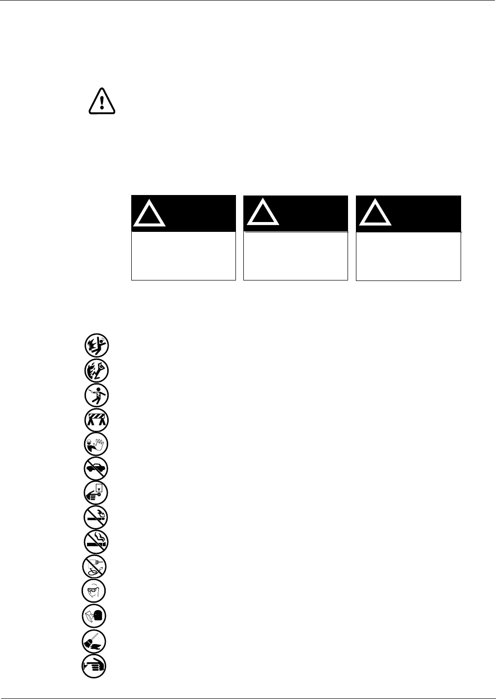
Alert Symbol and Signal Words
Alert Symbol:
This is a standard ANSI* approved alert symbol. When you see this symbol, be alert to the
potential for a personal injury.
* Reference American National Standard Bulletins ANSI Z535.
Signal Words:
These signal words alert you to important safety hazards.
Safety Symbols: The following safety symbols are used throughout this manual to alert you to personal safety
hazards and precautions.
Explosive
Flammable
Electrical hazard
Use safety barricades
No people in area
No vehicles in area
Use emergency power disconnect
No open flames
No smoking
No power tools
Wear eye protection
Read all related manuals
Clean up spills
Turn power off
!
WARNING
The hazard or unsafe
practice may result in
severe injury or death.
!
CAUTION
The hazard or unsafe
practice could result in
minor injury.
The hazard or unsafe
practice will result in
severe injury or death.
!
DANGER
OFF
Safety Information
Page 6 MDE-3801 TRIND™ Multi 1 Transmitter/Receiver in Dispenser Retrofit Kit • 10/99
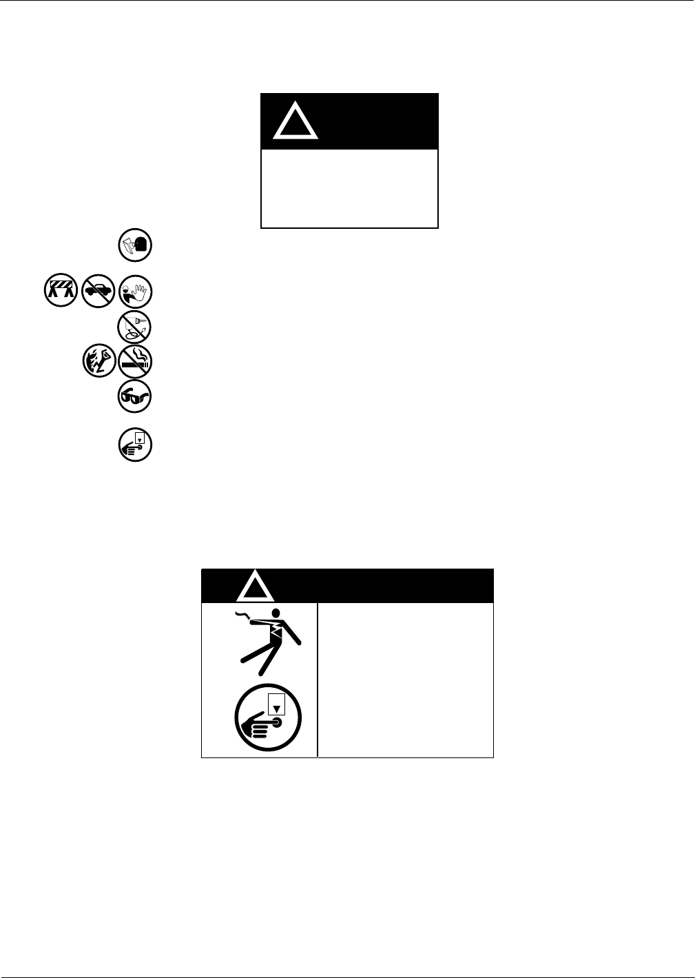
Before Beginning Do the following:
Read all instructions before beginning.
Follow all safety precautions, including:
• Barricade work area.
• Do not allow vehicles or unauthorized people in work area.
• Do not use power tools in work area.
• Do not permit smoking or open flames in work area.
• Wear protective gear while performing this installation.
Record all mechanical and electronic totals.
Turn off all power to unit, unit lights and STPs.
• Use system circuit breakers.
• Multiple disconnects may be required.
• Isolate each pump at distribution box.
• Refer to MDE-2531, Pump and Dispenser Start-up and Service for OSHA
lock-out/tag-out procedures.
When system battery is present, turn off system battery by pressing CLEAR then ENTER on
manager keypad.
WARNING
!
Dangerous Environment! Failure to
install this equipment in accordance
with NFPA 30A and NFPA 70 could
result in severe injury or death.
Read, understand and follow NFPA
30A and NFPA 70.
OFF
WARNING
Working on dispenser
electronics with power
applied may result in
electrocution and
damage to electronic
components.
Power down unit before
beginning work.
OFF
!

MDE-3801 TRIND™ Multi 1 Transmitter/Receiver in Dispenser Retrofit Kit • 10/99 Page 7
Safety Information
Use Electrostatic Discharge Precautions
Place yourself at a neutral static-free potential by doing the following:
1Touch an unpainted metal surface.
2Use a wrist strap connected to a grounded metal frame or chassis.
Note: Failure to use electrostatic discharge precautions may damage electronic components
and void warranty.
Make sure all power has been removed from unit and CRIND.
Follow OSHA Lock-Out and Tag-Out Requirements
OSHA Standard 29 CFR 1910-147 Control of Hazardous Energy Sources (Lock-Out/Tag-Out)
covers ways to avoid personal injury if power is turned on or fuel pressure is applied
unexpectedly while servicing equipment. The rule requires that equipment power and fuel
under pressure be turned off and the device (breaker, valve, etc.) locked or labeled with a
warning tag.
Read OSHA Standard 29 CFR 1910-147 Control of Hazardous Energy Sources (Lock-Out/
Tag-Out). Station employees and service contractors need to understand and comply with this
program completely to ensure safety while the equipment is down.
Tag-Out and Lock-Out Procedure
Use plastic warning tags with signature/date blanks for Tag-Out. Sign and date them at shut
down. Attach tags with plastic connectors.
Use metal screw-down lock clamps or plastic single or multi-pole devices for Lock-Out of
breakers and switches. Always use a lock-out device whenever possible.
When working on electronics and electrical connections (junction box):
• Turn off unit power, light breakers, and all dispensers sharing the same isolation relay
box.
• Install lock-out device and tag on breaker(s).
Note: If station does not use STP control wire isolation relays, multiple disconnects may be
required to shut off all power supplied to the unit.
OFF
Installation
Page 8 MDE-3801 TRIND™ Multi 1 Transmitter/Receiver in Dispenser Retrofit Kit • 10/99
Installation
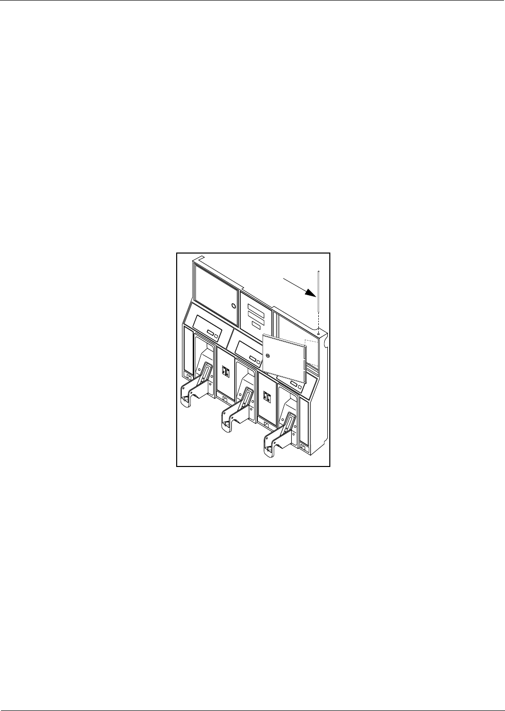
Preparing for Installation
1Before proceeding read and follow all safety instructions and procedures.
2Open main access doors. Refer to MDE-2531, Pump and Dispenser Start-Up/Service Manual
for access instructions.
3Disconnect and remove existing hardware according to the following:
• For wide frame units disconnect any cables and remove any call or stop buttons, or door
alarm switch hardware from existing right options door. Save all removed hardware for
reassembly.
• For narrow frame units disconnect cables to PPU and main display.
4Remove door mounting pin and right options door.
5If unit has Cash Acceptor, remove door alarm and all hardware from old door and save.
6Dispose of door. Save pin for reassembly.
S0001719
Pin
MDE-3801 TRIND™ Multi 1 Transmitter/Receiver in Dispenser Retrofit Kit • 10/99 Page 9
Installation
Modifying Right Options Door On Wide Frame Units
For all narrow frame units, or wide frame units without stop or call buttons or door alarm
switches, proceed to “Installing Cables” on page 13. For wide or narrow frame units without
stop or call units but with door alarm, proceed to “Re-installing Door Alarm Switches” on
page 12. For wide frame units with stop or call button previously installed on right options
door, do the following to relocate hardware to new TRIND Multi 1 options door.
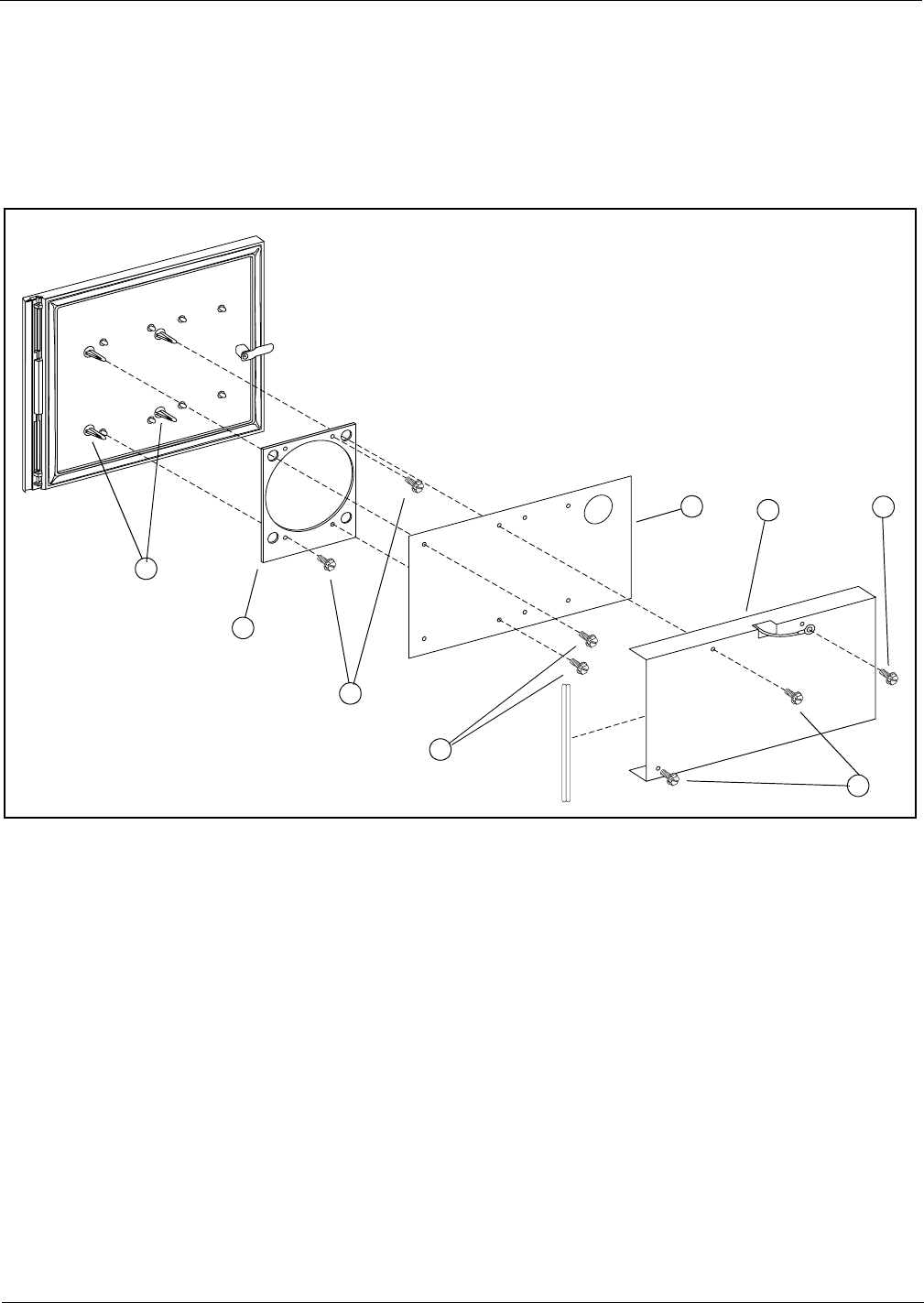
1Remove all hardware from new right options door according to the following steps and save
all parts for reassembly.
• Remove two screws (1) mounting sheet metal antenna shield (2) on rear of door. Save
shield and screws for reassembly.
Note: Screw (G) fastening grounding wire on side of sheet metal shield does not need to be
removed.
• Disconnect cable R20718-G1 from light/microreader printed circuit board T20545-G1 (3)
by disconnecting J191 on cable from P191 on board.
• Remove two standoff-screws (4) holding light/microreader board (3), and remove board.
Save for reassembly.
• Remove two screws (5) and carefully pry antenna board T20551-G1 (6) off four standoffs
(7) on door and save for reassembly.
S0001732
1
2
3
4
5
6
7
G
Installation
Page 10 MDE-3801 TRIND™ Multi 1 Transmitter/Receiver in Dispenser Retrofit Kit • 10/99
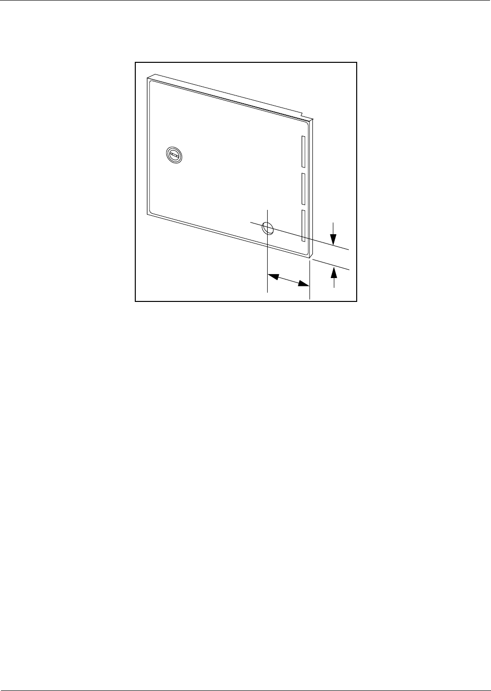
2Use center punch and hammer to mark placement of pump stop or call button hole on new right
options door by measuring from door edges as shown below.
3Away from fuel island, drill a 7/8 inch diameter hole in location illustrated above.
4Remove any burrs around hole with deburring tool or rounded file.
S0001734
1 9/16"
3 3/16"
MDE-3801 TRIND™ Multi 1 Transmitter/Receiver in Dispenser Retrofit Kit • 10/99 Page 11
Installation
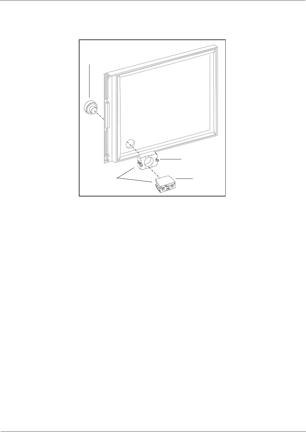
Re-installing Button
1Hold contact base on back of door and align with hole drilled earlier.
2Insert push button from front of door by aligning tabs with slots in base.
3Turn push button 45° clockwise to lock button to base.
4Tighten two screws on base to secure push button and base assembly to door.
Note: Do not overtighten screws.
5Attach contact block to base with center screw if not already installed.
6If unit does not have door alarm, reinstall all new right options door hardware except sheet
metal shield by reversing procedures in Step 1 of “Modifying Right Options Door On Wide
Frame Units” on page 9 and proceed to “Installing Cables” on page 13. If unit has door alarm,
proceed to “Re-installing Door Alarm Switches” on page 12.
S0001735
Push button
Contact switch
base assembly
Base
Contact
block
Installation
Page 12 MDE-3801 TRIND™ Multi 1 Transmitter/Receiver in Dispenser Retrofit Kit • 10/99
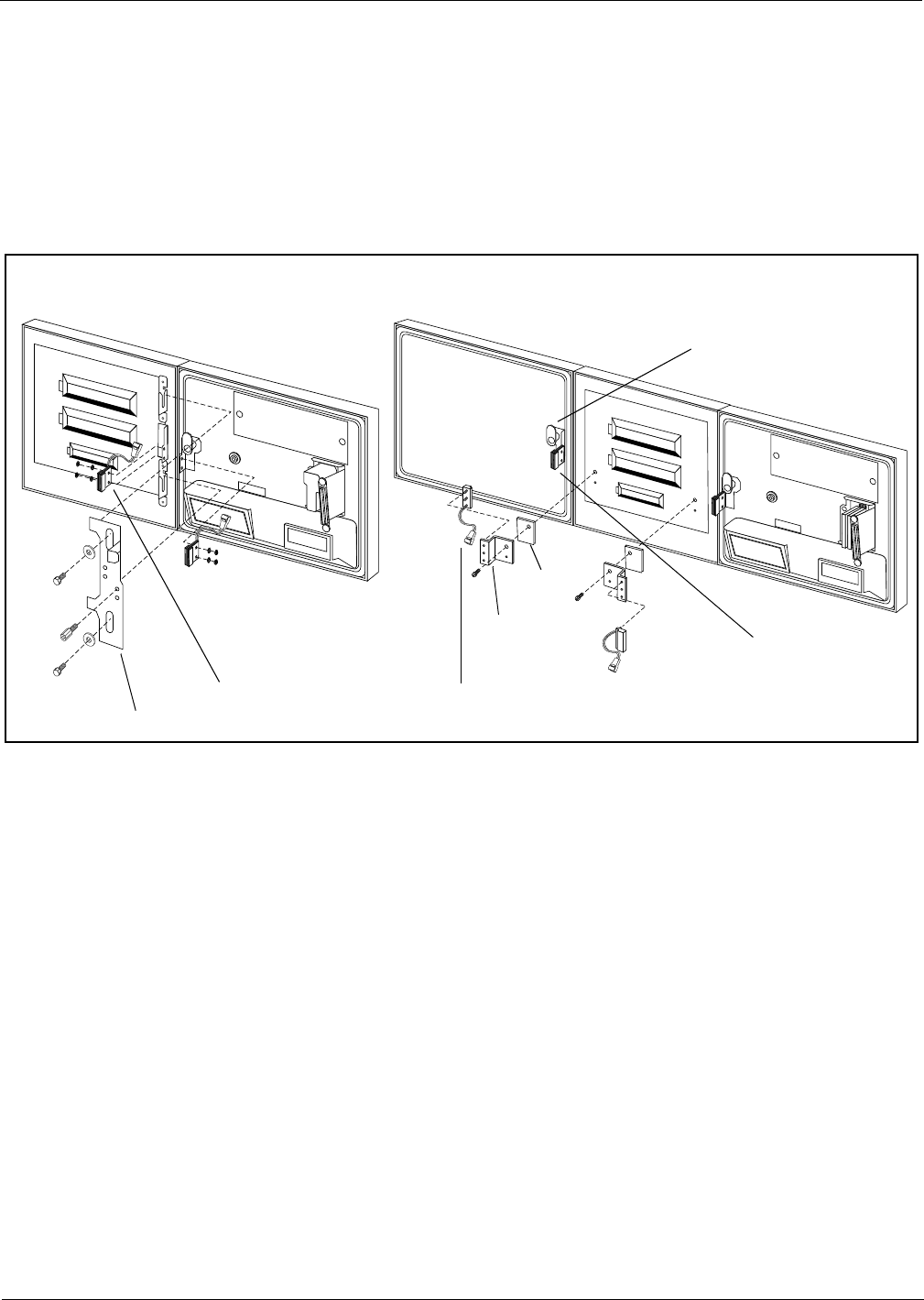
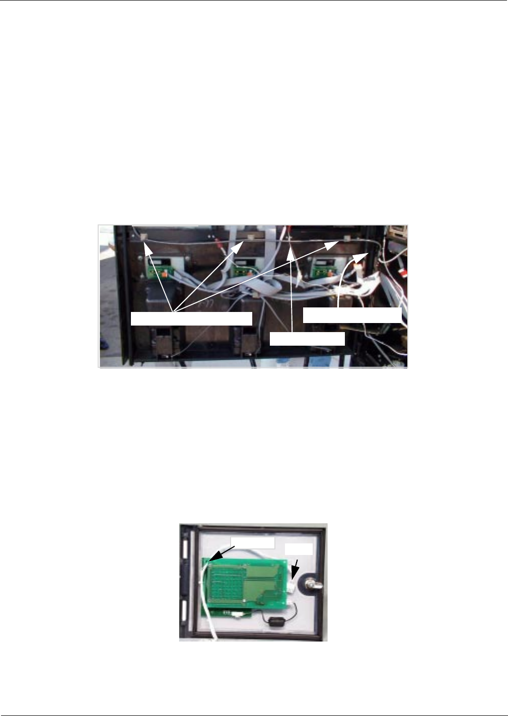
Re-installing Door Alarm Switches
For units with cash acceptors, follow these steps to re-install door alarm assemblies on
TRIND™ right option doors. Refer to diagram on this page for more information. Perform
each step for both ‘A’ and ‘B’ side right option doors.
1Remove lock hardware from new right options door.
1Re-install C-clips removed from old right side option doors on new door.
2Install door alarm assembly to door alarm assembly bracket with screw previously removed.
3Attach door alarm assembly bracket to display board with screw previously removed.
Note: Replace the piece of fiberboard between door alarm bracket assembly and display board.
4Be sure magnet does not touch door alarm door bracket. Slightly move door alarm door
bracket away, if necessary.
5Reinstall all new right options door TRIND hardware except sheet metal cover by reversing
procedures in Step 1 of “Modifying Right Options Door On Wide Frame Units” on page 9.
S0001736
S0001737
Back view of 36” Unit Option Doors Back view of 48” Unit Option Doors
Door alarm assembly bracket
Door alarm assembly
Right option door
C-clip
Door alarm door bracket
Fiber board
Door alarm
assembly bracket
Door alarm assembly
MDE-3801 TRIND™ Multi 1 Transmitter/Receiver in Dispenser Retrofit Kit • 10/99 Page 13
Installation
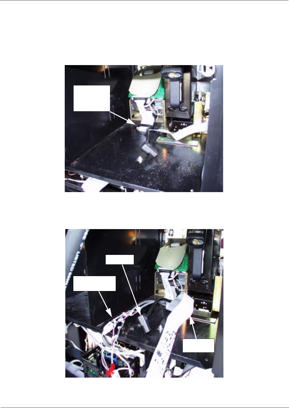
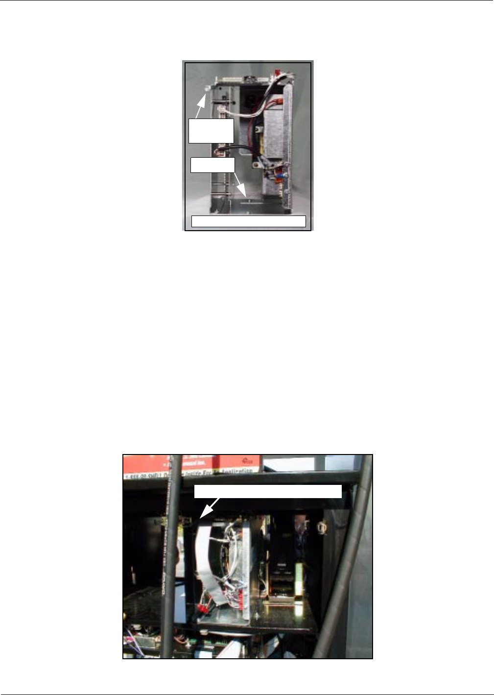
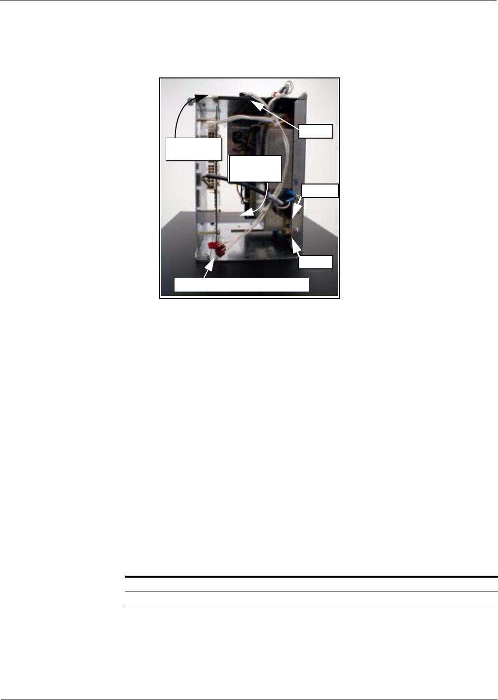
Installing Cables Position kit cables according to the following steps:
1Carefully pry out printer cable retainer from underside of printer shelf.
2Disconnect printer cable and pull cable out of 2 3/4" round hole from bottom, and install piece
of strip grommet Q10315-06/B around perimeter of hole.
3Feed three-prong end of power cable R20580-G2, J250 end of R20437-G01 ribbon cable and
multiple connector ends of cables R20665-G1 and R20665-G2 up through hole and lay cable
ends toward A side.
4Reinstall printer cable and retainer disconnected and removed in step 2.
2 3/4” printer
cable hole
and cable
retainer
R20437-G01
ribbon cable
R20665-G1 and
R20665-G2 cables
R20580-G2
Installation
Page 14 MDE-3801 TRIND™ Multi 1 Transmitter/Receiver in Dispenser Retrofit Kit • 10/99
Installing Card Cage Prepare T20538-G1 card cage for installation.
Note: For more cable connection detail see “Cable Block Diagrams” on page 24.
1Locate tab at left front top of card cage.
2From B side of unit, turning card cage sideways to unit, feed top and rear of card cage up and
into shelf.
Note: Front of card cage will face B side.
3Position card cage so that tab fits over latch cutout for main door latch to secure card cage to
shelf divider. Note position of two screws protruding from bottom of card cage:
• For newer units, both screws will pass through holes in printer shelf.
• For older units, holes will not align with holes in shelf. Remove both screws and save.
4Position rear of card cage on edge of cabinet shelf for easy cable connection.
Note: Do not secure card cage at this time. Connecting cables and setting jump jacks are
easier if card cage can be manipulated by installer.
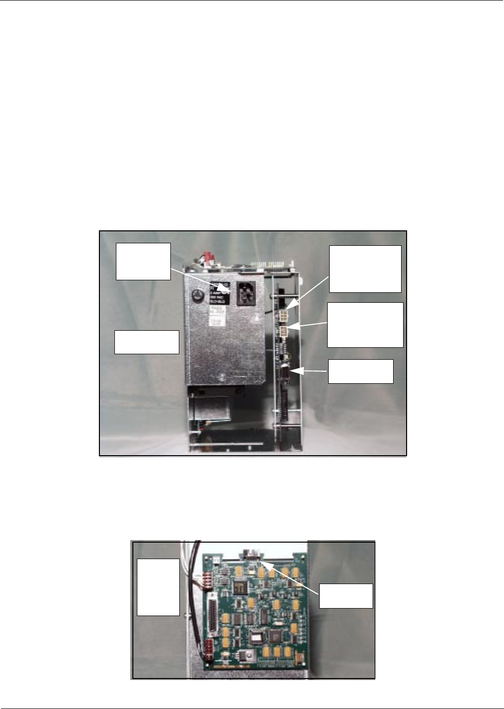
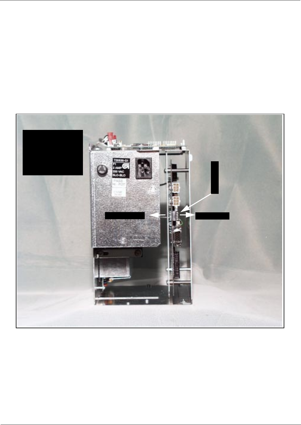
5Connect three prong female end of power cable R20580-G2 to card cage at location shown.
6Connect P7 on R20665-G1 to J7 and P8 on R20665-G2 to J8 on DCB at location shown.
7Connect J186 on R20724-G1 cable to P186 on Gateway Board on top of card cage.
J8 on DCB for
P8 on
R20665-G2 for
B side
J7 on DCB for
P7 on
R02665-G1 for
A side
RS232 Port
Rear side of card
cage shown
Connect
R20580-G2
power cable
For J186 on
R20724-G1
Gateway
board on
top of
card
cage
MDE-3801 TRIND™ Multi 1 Transmitter/Receiver in Dispenser Retrofit Kit • 10/99 Page 15
Installation
Address Gateway Board Before Installing Card Cage
Address for TRIND™ must match address on CRIND® logic board. Follow these steps:
1From A side of unit lower CRIND tray. Refer to MDE-2562 CRIND Service Manual.
2Locate jump jacks on A and B side CRIND logic boards T17764-XX.
3Note position of jump jacks and set jump jacks on Gateway board T20128 to match address on
CRIND logic boards for both A and B sides.
MOC and Generic CRIND Addresses.
Address On CRIND Logic Board T17764-XX JP8 JP7 JP6 JP5 JP4
= Address on Gateway Board T20128 ‘A’ Side JP6 JP7 JP8 JP9 JP10
= Address on Gateway Board T20128 ‘B’ Side JP14 JP15 JP16 JP17 JP18
1 IN OUT OUT OUT OUT
2 OUT IN OUT OUT OUT
3 IN IN OUT OUT OUT
4 OUT OUT IN OUT OUT
5 IN OUT IN OUT OUT
6 OUT IN IN OUT OUT
7 INININOUTOUT
8 OUT OUT OUT IN OUT
9 INOUTOUTINOUT
10 OUT IN OUT IN OUT
11 IN IN OUT IN OUT
12 OUT OUT IN IN OUT
13 IN OUT IN IN OUT
14 OUTINININOUT
15 IN IN IN IN OUT
16 OUT OUT OUT OUT IN
17 IN OUT OUT OUT IN
18 OUT IN OUT OUT IN
19 IN IN OUT OUT IN
20 OUT OUT IN OUT IN
21 IN OUT IN OUT IN
22 OUT IN IN OUT IN
23 IN IN IN OUT IN
24 OUT OUT OUT IN IN
25 IN OUT OUT IN IN
26 OUT IN OUT IN IN
27 IN IN OUT IN IN
28 OUT OUT IN IN IN
29 IN OUT IN IN IN
30 OUTININININ
31 IN IN IN IN IN
32 OUT OUT OUT OUT OUT
Jump jack locations on Gateway Board
Installation
Page 16 MDE-3801 TRIND™ Multi 1 Transmitter/Receiver in Dispenser Retrofit Kit • 10/99
Install card cage assembly.
Install card cage by doing the following:
Note: While it is not necessary to remove printer to install card cage you may find your initial
installations easier if this is done. To do so, disconnect two cables and remove ground
connector to A side printer. Remove printer and printer mounting hardware from unit
and save for reinstallation.
1Locate tab at left front top of card cage.
2From B side, turn card cage sideways to unit, feed top and rear of card cage up and into shelf.
Note: Front of card cage will face B side.
3Position card cage so that tab fits over latch cutout for main door latch, securing card cage to
shelf divider.
• If two screws on card cage pass through shelf secure from underside of shelf with two nuts
provided in kit.
• If screws were removed, secure card cage from underside of shelf by installing one screw
removed in section “Prepare T20538-G1 card cage for installation.” on page 14 up
through hole in shelf to clinch nut on card cage (see illustration above). Dispose of second
screw and two nuts.
Tab on
card cage
card cage front facing B side
clinch nut
Tab locks into shelf divided at latch cut-out
MDE-3801 TRIND™ Multi 1 Transmitter/Receiver in Dispenser Retrofit Kit • 10/99 Page 17
Installation
Installing Right Option Door
Mount New Right Options Door
Install new right options door according to the following steps.
1If sheet metal shield has not been previously removed, using 1/4’’ nut driver, remove sheet
metal shield from back of door. Refer to illustration in “Modifying Right Options Door On
Wide Frame Units” on page 9 for detail. Save cover and hardware.
2Remove key taped to inside of new right options door and save.
3Position new right options door and install with pin removed with old door and saved.
Note: If unit had stop or call button transferred from old door to new TRIND door, reconnect
stop or call button wires to contact block.
Route cables to Right Option Doors
Note: Cable R20665-G1 to A side is shorter than B side cable R20665-G2
1Route A side cable R20665-G1 through cable clamp inside door and secure along door with
clamps provided with kit.
2Route B side cable through clamps above CRIND tray to cable clamp inside door, and secure
along door with clamps provided with kit.
Note: When routing from cabinet to main door, allow sufficient slack in cables to allow main
door to open and close without pulling or crimping cables. Also check that cable is not
crimped when door is closed.
3Route cables around board as shown for both wide and narrow frame units, securing cable to
board with tie-wrap.
4Connect J182 on each cable to P182 on PCB assembly on option door.
5Reinstall sheet metal cover on door, being careful to avoid crimping cables.
Cable clamps provided with kit
R20665-XX cable
Cable clamp inside door
tie-wrap J182
Installation
Page 18 MDE-3801 TRIND™ Multi 1 Transmitter/Receiver in Dispenser Retrofit Kit • 10/99
Connecting Remaining Cables
1From A side, pass J250 end of cable R20437-G01, J176 and JA ends of cable R20665-G1 and
J177 and PA ends of cable R20665-G2 through card cage to B side.
2From B side, connect J176 on cable R20665-G1 to P176 on Power Supply PCB.
Note: Detailed information provided on “Cable Block Diagrams” on page 24.
3Connect J177 on cable R20665-G2 to P177.
4Connect JA on R20665-G1 to PA on R20724-G1 cable.
5Connect PA on R20665-G2 cable to JA on R20724-G1 cable.
6Connect J250 on ribbon cable R20437-G01 to P250 on Gateway board on top of card cage.
From A side of unit make the following connections:
1On ribbon cable R20437-G01, connect J258A to P258 on A side CRIND Logic Board.
Note: A side of split cable R20437-G01 has red wire.
2On ribbon cable R20437-G01, connect J258B to P258 on B side CRIND Logic Board.
Connect R20580-G2 power cable according to the following:
Note: Connections are unit specific. Use appropriate connectors to intercept power by
installing R20590-G1 inline.
For units with: Do the following:
System cable W02468 Install inline using 15 pin P601 and J601 connectors
System cable T19612 Install inline using 3 pin connectors J601/J708 and P601/P708
P186
P176
P177
JA and PA connectors on R20724-G1
pass cables
through cage
P250 on
Gateway Board
MDE-3801 TRIND™ Multi 1 Transmitter/Receiver in Dispenser Retrofit Kit • 10/99 Page 19
CRIND® BIOS TRIND™ Multi 1 Upgrade
CRIND® BIOS TRIND™ Multi 1 Upgrade
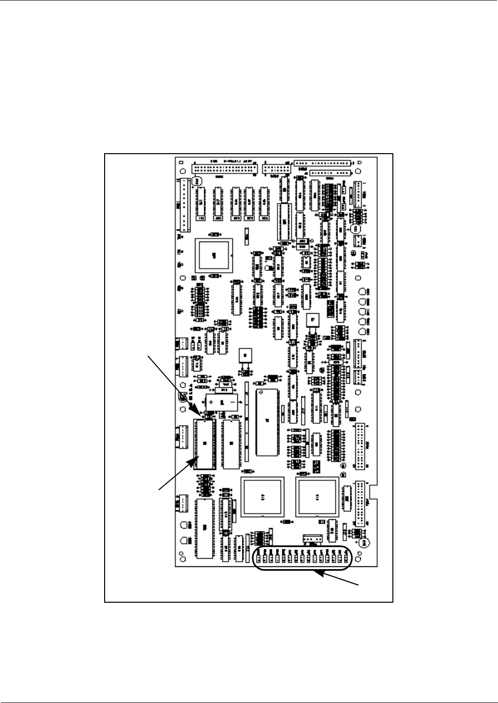
Units must have current Z-180 CRIND logic board.
Install the CRIND Bios TRIND software K93744-01, one per logic board, on the T17764-XX
CRIND logic board(s) according to the following steps.
Note: A properly grounded electrostatic discharge wrist strap must be worn during this
procedure.
U7
Chip
orientation
notch
T17764-XX
CRIND
logic board
(-G3 shown)
JP1-16
CRIND® BIOS TRIND™ Multi 1 Upgrade
Page 20 MDE-3801 TRIND™ Multi 1 Transmitter/Receiver in Dispenser Retrofit Kit • 10/99
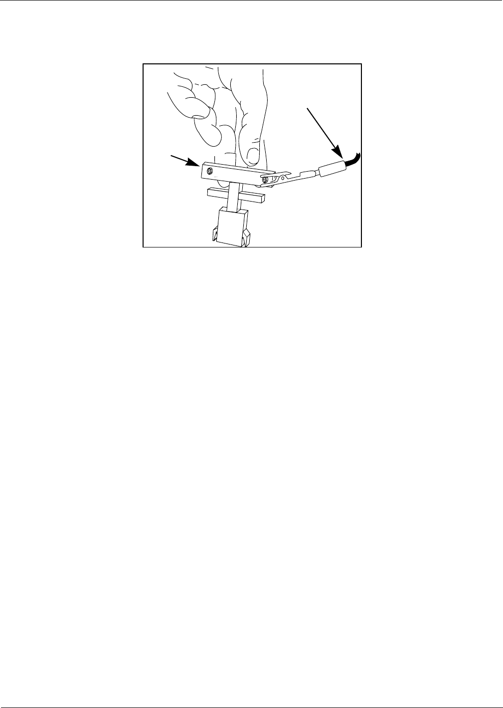
1Locate and remove existing BIOS at U7 on CRIND® logic board T17764-XX using a
grounded chip removal tool.
.
2Install TRIND BIOS K93744-01 (one per logic board) at position U7, orienting notch on chip
with indication mark on board as shown.
3Install jump jack on JP-16 for each side of unit.
Note: Jumper on JP-16 informs the CRIND that a TRIND system is present.
4Restore CRIND tray to operating position.
Chip
removal
tool
Grounding strap
MDE-3801 TRIND™ Multi 1 Transmitter/Receiver in Dispenser Retrofit Kit • 10/99 Page 21
Dispenser Set-Up
Dispenser Set-Up
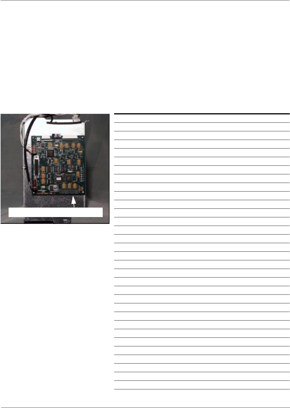
Addressing DispenserEach dispenser on the G-Site controller must be addressed differently; no two dispensers may
have the same address. Address is at discretion of the installer. Follow these steps:
1From A side of unit, locate dip switches on power supply board (PCB) T20314-G1 in card
cage.
2Using switches 2, 3, 4 and 5 address each dispenser according to the following table:
Note: Switch one in down position is standalone mode selected, used for service only.
Setting Baud Rate For major oil company (MOC) TRIND™ installations there is no requirement to set or change
baud rate.
Switch Numbers = Value
1 = Standalone Mode
2 = 1
3 = 2
4 = 4
5 = 8 1
2
3
4
5
Dip switch down Dip switch up
Dispenser Set-Up
Page 22 MDE-3801 TRIND™ Multi 1 Transmitter/Receiver in Dispenser Retrofit Kit • 10/99
Testing TRIND™ Multi 1
1If printer was removed, replace printer and reconnect two cables and ground.
2Restore power to unit. Refer to Pump and Dispenser Service Manual MDE-2531.
3Restoring power with new Bios will Cold Start the CRIND. Refer to CRIND Service Manual
MDE-2562.
Note: Cold Start is required if TRIND equipment is installed or changed.
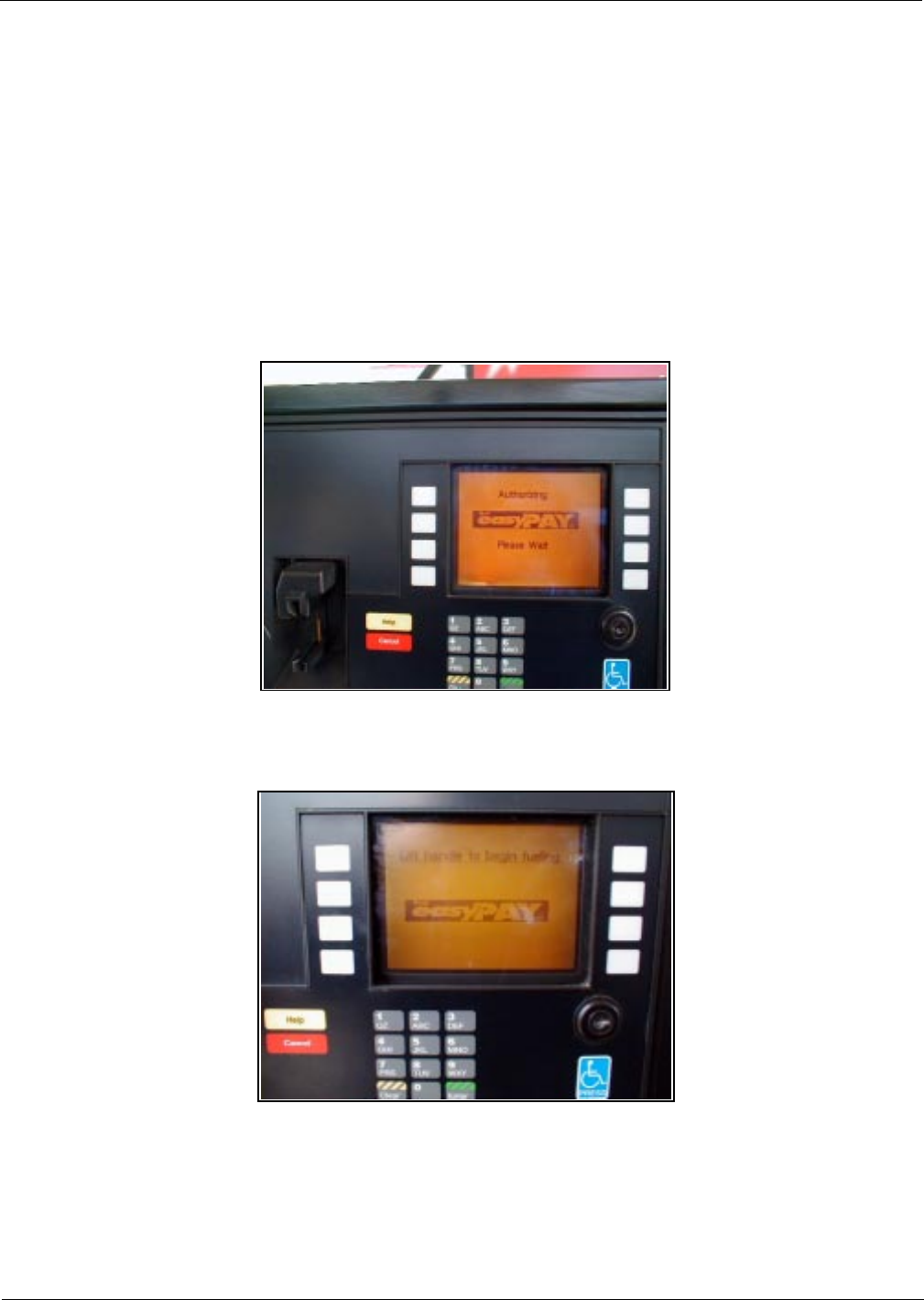
4Present test tag at option door from a distance of 6’’ or less. Light board should light and flash
sequentially and emit one beep. Screen prompt should appear as shown.
Note: If light does not function properly, check to see if opposite side of unit was activated,
indicating a crossed cable.
5When using test tag, screen will show “Test Confirmed”. In regular operation, screen will
display the following.

MDE-3801 TRIND™ Multi 1 Transmitter/Receiver in Dispenser Retrofit Kit • 10/99 Page 23
Dispenser Set-Up
Completing Installation
1Close and secure option and maindoor.
2Install graphics. Refer to MDE-2620 Graphics Installation for The Advantage Series.
3Peel backing paper off FCC label pate provided in kit.
4Affix FCC label plate to inside frame sheathing on column under existing FCC label.
5Restore power to unit. Refer to Pump and Dispenser Service Manual MDE-2531.
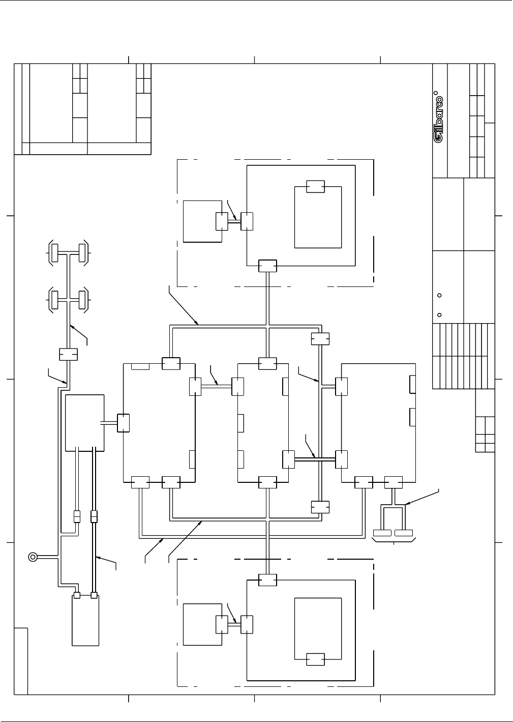
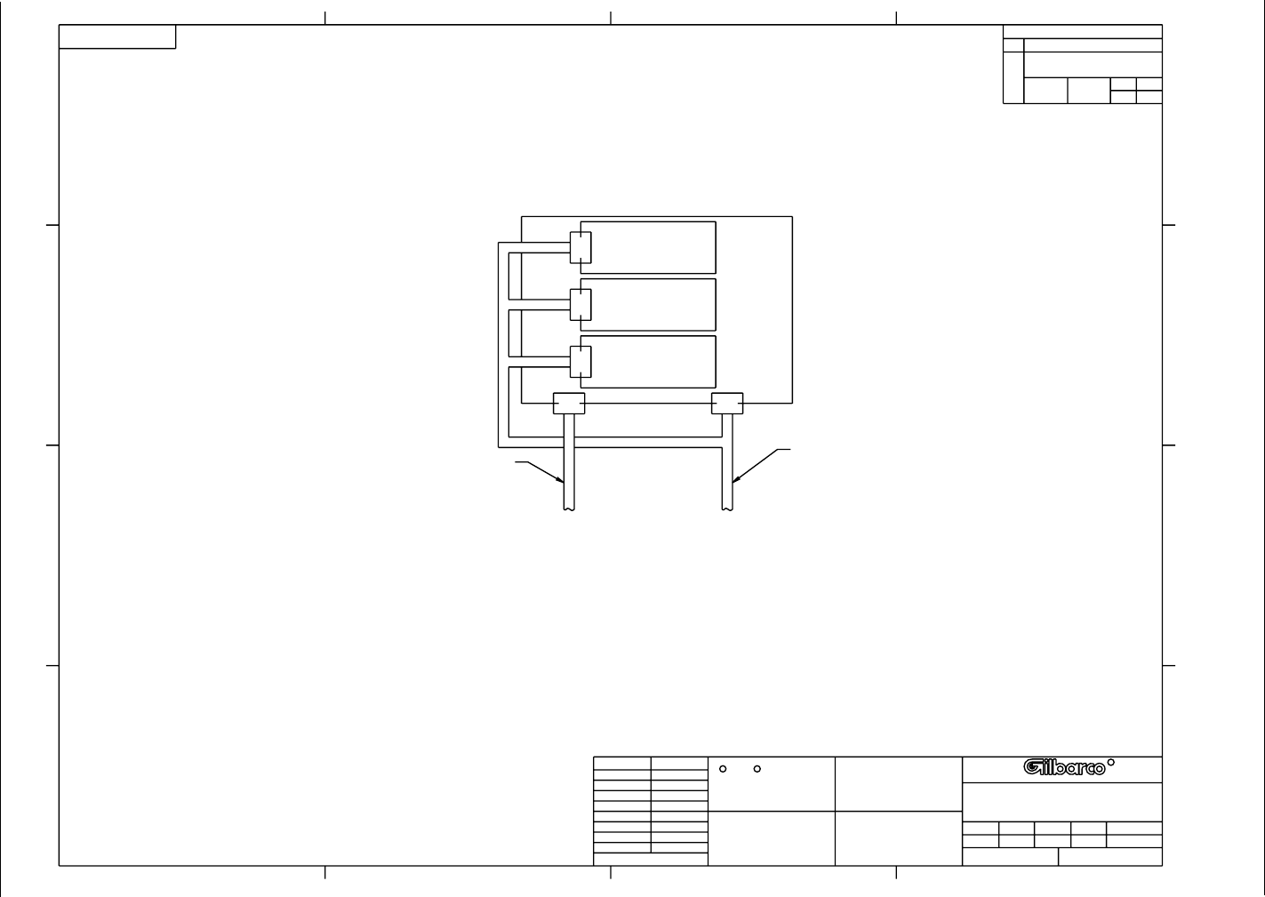
Cable Block Diagrams
Page 24 MDE-3801 TRIND™ Multi 1 Transmitter/Receiver in Dispenser Retrofit Kit • 10/99
Cable Block Diagrams
RC
R
TRIND MULTI_1 WMH NONE
R20720
R20720
DIAGRAM, TRIND
MULTI_1, BLOCK
64301-0
07/13/99
1 OF 2
2
J812
U812
J2 9
P181
R20718 G1
INDICATOR
LIGHT BOARD
Q13786 01
16
J181
A
JTB
08/26/99
64455-0
EAN:
REVISED SH INDEX
CHNG: R20206 G10
WAS G9. RMV:
CONNECTION E2;
DASHES FROM ALL
PART NUMBERS.
B REVISED SH INDEX.
ADDED: R20543 G3
& R20206 G11.
RMV: Q10895 01
FILTER; R20206 G9;
R20543 G1; AND
R20543 G2.
WMH
09/10/99
64489-0
EAN:
1
1
1
ANTENNA
HAND HELD
T20551 G1
2
P191
J191
LIGHT/MICROREADER
P.C.B. ASSEMBLY
T20545 G1
INDICATOR
LIGHT BOARD
Q13786 01
10
J182 P182
16
P181 J181
"B" SIDE
P191 2
J191
2
J812
U812
ANTENNA
HAND HELD
T20551 G1
R20718 G1
T20538
3
P3
R20206 G11
P188
4
5
J174
2
P174
3
6
14
P250
P185
P187
P251A
J187
J185
J182
10
P182
B
A
7
7
1
1
2
J258B
J258A
AC PWR
3
3
15
15
P601
J601
J176
P176
R20580 G1
"A" SIDE
J250
R20437 G01
R20524 G3
R20665 G1 R20665 G2
TO P601/P708
MAIN POWER
SUPPLY ASSY
TI/RFID
TRANSFORMER
SUBASSY
R20719 G1
R20724 G1
R20524 G2
TI GATEWAY
P.C.B. ASSEMBLY
T20128 G2
POWER SUPPLY
P.C.B. ASSEMBLY
T20314 G1
LIGHT/MICROREADER
P.C.B. ASSEMBLY
T20545 G1
J601/
J708
P601/
P708
TO J601/J708
SYSTEM CABLE
T19612
TO J601
SYSTEM CABLE
W02468
TO P601
MAIN POWER
SUPPLY ASSY
TO CRIND LOGIC
SEE (T19503)
3
P177
J177
P175
2J175
P173
10
P179
J179 2
P178
3
2
8
DATA CONTROL
BOARD Q13563 03
P3
J3
J6 10
P8 J8
6
P7J7
6
J4
P4 4J5 4
10
P186
J186
2PA
JA
2
JA PA
R20525 G1
1
1
AC FUSE
Q10131 02
R20543 G3
E1
SHEET
INDEX
REV
SH 12
BA
B
A
C
D
43 21
A
B
C
D
1234
CK APP
TR
FRACTIONS:±
ANGLES:±
REVISIONS
SYM DESCRIPTION
DR SCALE
SH
NO.
EAN NO. SYM
NO.
FINAL PROTECTIVE FINISH
MATERIAL
UNLESS OTHERWISE SPECIFIED:
DIMENSIONS ARE IN INCHES.
TOLERANCES ON
DECIMALS:
2 PLACE ±
3 PLACE ±
NEXT ASSY USED ON
APPLICATION
GILBARCO CONFIDENTIAL
GILBARCO INC. UNPUBLISHED
GREENSBORO, N.C.
THIS PRINT IS THE PROPERTY OF
GILBARCO INC., N.C., U.S.A.
INFORMATION HEREON IS CONFIDENTIAL
AND MUST NOT BE REPRODUCED OR
RELEASED OUTSIDE GILBARCO WITHOUT
PROPER AUTHORIZATION.
S0001730 -
--
-
MDE-3801 TRIND™ Multi 1 Transmitter/Receiver in Dispenser Retrofit Kit • 10/99 Page 25
Cable Block Diagrams
RC
R
TRIND MULTI_1 WMH NONE
R20720
R20720
DIAGRAM, TRIND
MULTI_1, BLOCK
64301-0
07/13/99
A
JTB
08/26/99
64455-0
EAN:
RMV: DASHES FROM
ALL PART NUMBERS
T20538
NARROW FRAME DOOR ONLY
3
3
P802
20 34
P801
J804
P804
P802
J802C
J802B
J802A
J801
3
P802
BACKLITE
LCD
DISPLAY
ASSEMBLY
T20262
REFLECTOR ASSY
0.6 INCH
T17622 G9
REFLECTOR ASSY
0.6 INCH
T17622 G9
REFLECTOR ASSY
0.6 INCH
T17622 G9
P/O W03715 G2
P/O T19793 G3
2
B
A
C
D
43 21
A
B
C
D
1234
CK APP
TR
FRACTIONS:±
ANGLES:±
REVISIONS
SYM DESCRIPTION
DR SCALE
SH
NO.
EAN NO. SYM
NO.
FINAL PROTECTIVE FINISH
MATERIAL
UNLESS OTHERWISE SPECIFIED:
DIMENSIONS ARE IN INCHES.
TOLERANCES ON
DECIMALS:
2 PLACE ±
3 PLACE ±
NEXT ASSY USED ON
APPLICATION
GILBARCO CONFIDENTIAL
GILBARCO INC. UNPUBLISHED
GREENSBORO, N.C.
THIS PRINT IS THE PROPERTY OF
GILBARCO INC., N.C., U.S.A.
INFORMATION HEREON IS CONFIDENTIAL
AND MUST NOT BE REPRODUCED OR
RELEASED OUTSIDE GILBARCO WITHOUT
PROPER AUTHORIZATION.
S0001731 -
--
-

Cable Block Diagrams
© 1999 Gilbarco, Inc. • 7300 West Friendly Avenue • Post Office Box 22087 • Greensboro, North Carolina 27420 • Phone (336) 547-5000 • http://www.gilbarco.com
MDE- 3801 10/99 Printed in the U.S.A.