Gilbarco MRIR11 Point of Sale Mat Reader System User Manual
Gilbarco Inc. Point of Sale Mat Reader System
Gilbarco >
Manual

MDE-4017 TIRIS™ Transmitter/Receiver Mat Reader Assembly Kit C00016-XXX Installation • May 2001 Page 1
Preliminary
05/24/01
Introduction
Purpose of this Manual
This manual provides instruction for installing TIRIS™ Mat Reader Assembly Kit C00016-
XXX.
The TIRIS™ option allows customers to automatically authorize non-cash sales using a hand-
held transponder tag.
Important Notice
This equipment has been tested and found to comply with the limits for a Class A digital
device pursuant to Part 15 of the FCC Rules. These limits are designed to provide reasonable
protection against harmful interference when the equipment is operated in a commercial
environment. This equipment generates, uses and can radiate radio frequency energy, and if
not installed and used in accordance with the instruction manual, may cause harmful
interference to radio communications. Operation of this equipment in a residential area is
likely to cause harmful interference in which case the user will be required to correct the
interference at his own expense. Changes or modifications not expressly approved by the
manufacturer could void the user’s authority to operate this equipment.
The long term characteristics or the possible physiological effects of radio frequency
electromagnetic fields have not been investigated by Underwriters’ Laboratories, Inc. (UL®).
Required Reading
Before installing the equipment, the installer must read, understand, and follow:
•this manual
•NFPA 70, The National Electric Code
•applicable federal, state and local codes and regulations
Failure to do so may adversely effect the safe use and operation of the equipment.
MDE-4017
TIRIS™ Transmitter/Receiver Mat Reader
Assembly Kit C00016-XXX Installation
May 2001

Page 2 MDE-4017 TIRIS™ Transmitter/Receiver Mat Reader Assembly Kit C00016-XXX Installation • May 2001
Preliminary
05/24/01
Related Documents
Installer must obtain, read and understand all site preparation documentation provided by the
point of sale company authorizing the installation before attempting to install this equipment.
In addition, the installer must be familiar with the information in the following documents.
Required Tools
The following equipment is needed to install all TIRIS™ mat reader kits:
•drill motor and bits
•needle nose pliers
•screwdriver, Phillips® head
•Zircon® stud/bracket finder
Parts Lists C00016-006 Kits contain the following parts:
The following components are also required.
Document
Number Title GOLD Library
MDE-3110 PC-Based G-SITE System Installation Manual G-SITE
MDE-3111 PC-Based G-SITE System Start-Up and Service Manual • G-SITE
• Service Manual
MDE-3620 Gilbarco POS Console Site Preparation Manual Site Prep
Description Part Number Quantity
box, interface assembly M01814A001 1
tape, neoprene foam M01870B001 2
channel, plastic filler M01871B001 1
cable, mat reader drive M01872A001 1
tape, acrylic foam K85492-72 1
power supply M01878B001 1
jack, jump, push-to-start Q11011-01 1
cable, data, CAT-5 Q13482-06 1
clamp, cable, stick on, small Q13459-01 3
document, installation (this document) MDE-4017 1
diagram, block and/or interconnect M01873 0
Description Part Number Quantity
graphics MR01002G003 1
reader, mat, TIRIS device
Note: The Mat Reader is delivered with
the graphics in place.
M01787B001 1

Page 3 MDE-4017 TIRIS™ Transmitter/Receiver Mat Reader Assembly Kit C00016-XXX Installation • May 2001
Preliminary
05/24/01
Important Safety Information
This section introduces the hazards and safety precautions associated with installing,
inspecting, maintaining or servicing this product. Before performing any task on this product,
read this safety information and the applicable sections in this manual, where additional
hazards and safety precautions for your task will be found. Electrical shock could occur and
cause death or serious injury if these safe service procedures are not followed.
Preliminary Precautions
Read, understand and follow this manual and any other labels or related materials supplied
with this equipment.
Follow the Regulations
There is applicable information in: NFPA 70: National Electrical Code (NEC); OSHA
regulations; and federal, state, and local codes which must be followed. Failure to install,
maintain or service this equipment in accordance with these codes, regulations and standards
may lead to legal citations with penalties or affect the safe use and operation of the equipment.

Page 4 MDE-4017 TIRIS™ Transmitter/Receiver Mat Reader Assembly Kit C00016-XXX Installation • May 2001
Preliminary
05/24/01
Safety Symbols and Warning Words
Alert Symbol
This safety alert symbol is used in this manual and on warning labels to alert you to a
precaution which must be followed to prevent potential personal safety hazards. Obey safety
directives that follow this symbol to avoid possible injury or death.
Signal Words
These signal words used in this manual and on warning labels tell you the seriousness of
particular safety hazards. The precautions that follow must be followed to prevent death,
injury or damage to the equipment.
Proper Grounding is Required
Proper grounding is required for safe operation. See installation manual and applicable NEC,
NFPA and local electrical codes for requirements.
Avoid Pinched Wires
Pinched or cut wires (cables) may damage components. Exposed wires could create sparks and
electrical shorts when applying power.
Other Useful Safety Information
Replacement Parts
Use only genuine Marconi replacement parts. Using parts other than genuine Marconi
replacement parts could create a safety hazard, violate national, state and local regulations or
void warranty.
This signal word designates a hazard or unsafe practice which may result in minor injury.
This signal word is used to alert you to a hazard or unsafe practice which will result in
death or serious injury.
This alerts you to a hazard or unsafe practice that could result in death or serious injury.
CAUTION
When used by itself, CAUTION designates a hazard or unsafe practice which may result in
property or equipment damage.
CAUTION
DANGER
WARNING
Page 5 MDE-4017 TIRIS™ Transmitter/Receiver Mat Reader Assembly Kit C00016-XXX Installation • May 2001
Preliminary
05/24/01
Installation Note: All installation work is to be accomplished between the hours specified by the point of
sale company authorizing the installation.
Install Mat Reader assembly according to the following:
1Collect and arrange all tools and equipment.
2If necessary for installation of kit in area specified by point of sale company, remove
advertisement panels, saving all mounting hardware for re-use later.
Note: Make note of non-reusable fasteners, ensuring adequate replacements are available for
later use.
Setting Baud Rate
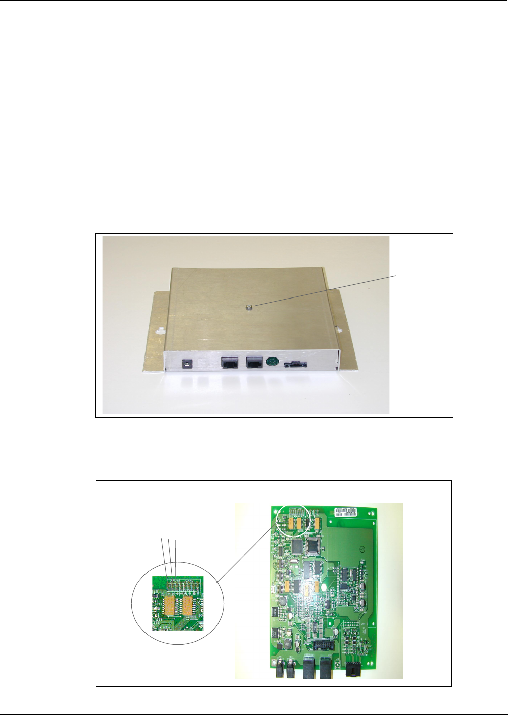
1Remove Mat Reader Interface Box cover to access logic board.
Figure: Mat Reader Interface Box Cover
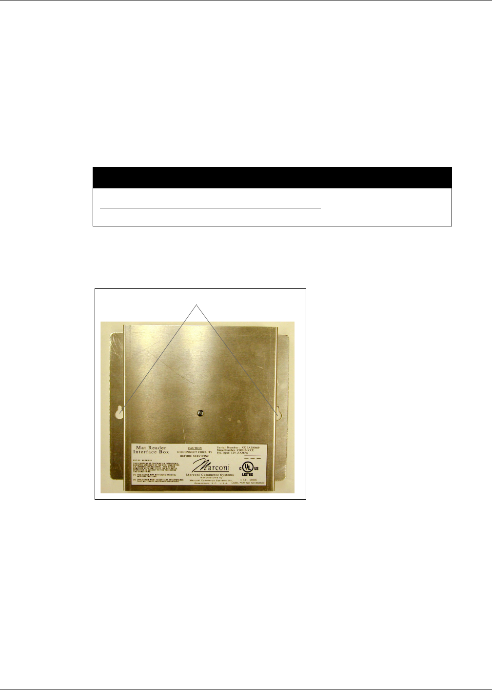
2Locate jump jacks on logic board for Mat Reader.
Figure: Jump Jacks for Baud Rate Setting
cover screw
BAUD
1 2 4

Page 6 MDE-4017 TIRIS™ Transmitter/Receiver Mat Reader Assembly Kit C00016-XXX Installation • May 2001
Preliminary
05/24/01
3Set the jump jacks as follows (see “Figure: Jump Jacks for Baud Rate Setting” on page 5).
4If not daisychaining Mat Reader Interface Boxes, reinstall cover.
Note: Daisychaining is connecting the output from one Interface Box to the input of another.
Addressing Logic Board - Only for Daisychaining
Address for Mat Reader must match address on previously installed Mat Reader. Follow these
steps:
1Access logic board for Mat Reader being installed.
2Locate jump jacks on previously installed Mat Reader logic board M01803A001.
Figure: Jump Jacks for Address Setting
Mat Reader Baud Rates
Baud Rate (Note) BAUD 1 BAUD 2 BAUD 4
4800 OUT OUT OUT
2400 IN OUT OUT
1200 OUT IN OUT
300 IN IN OUT
38400 OUT OUT IN
19200 IN OUT IN
9600 OUT IN IN
4800 IN IN IN
Note: 4800 is the default value and the Mat Reader value.
Electrostatic Discharge Damage
Working on electronics without connecting to a ground or discharging
static can damage electronic parts. Use a wrist strap.
CAUTION
ADDR
1 2 4 8 16

Page 7 MDE-4017 TIRIS™ Transmitter/Receiver Mat Reader Assembly Kit C00016-XXX Installation • May 2001
Preliminary
05/24/01
3Note position of jump jacks on previously installed Mat Reader logic board, and set jump
jacks on board for Mat Reader being installed to match address on logic board.
4Reinstall cover.
Mat Reader Addresses
Address on Logic Board
M01803A001 ADDR 1 ADDR 2 ADDR 4 ADDR 8 ADDR 16
0 OUT OUT OUT OUT OUT
1 IN OUT OUT OUT OUT
2 OUT IN OUT OUT OUT
3 IN IN OUT OUT OUT
4 OUT OUT IN OUT OUT
5 IN OUT IN OUT OUT
6 OUT IN IN OUT OUT
7 INININOUTOUT
8 OUT OUT OUT IN OUT
9 IN OUT OUT IN OUT
10 OUT IN OUT IN OUT
11 IN IN OUT IN OUT
12 OUT OUT IN IN OUT
13 IN OUT IN IN OUT
14 OUTINININOUT
15 IN IN IN IN OUT
16 OUT OUT OUT OUT IN
17 IN OUT OUT OUT IN
18 OUT IN OUT OUT IN
19 IN IN OUT OUT IN
20 OUT OUT IN OUT IN
21 IN OUT IN OUT IN
22 OUTININOUTIN
23 IN IN IN OUT IN
24 OUT OUT OUT IN IN
25 IN OUT OUT IN IN
26 OUT IN OUT IN IN
27 IN IN OUT IN IN
28 OUT OUT IN IN IN
29 IN OUT IN IN IN
30 OUTININININ
31 IN IN IN IN IN
Electrostatic Discharge Damage
Working on electronics without connecting to a ground or discharging
static can damage electronic parts. Use a wrist strap.
CAUTION
Page 8 MDE-4017 TIRIS™ Transmitter/Receiver Mat Reader Assembly Kit C00016-XXX Installation • May 2001
Preliminary
05/24/01
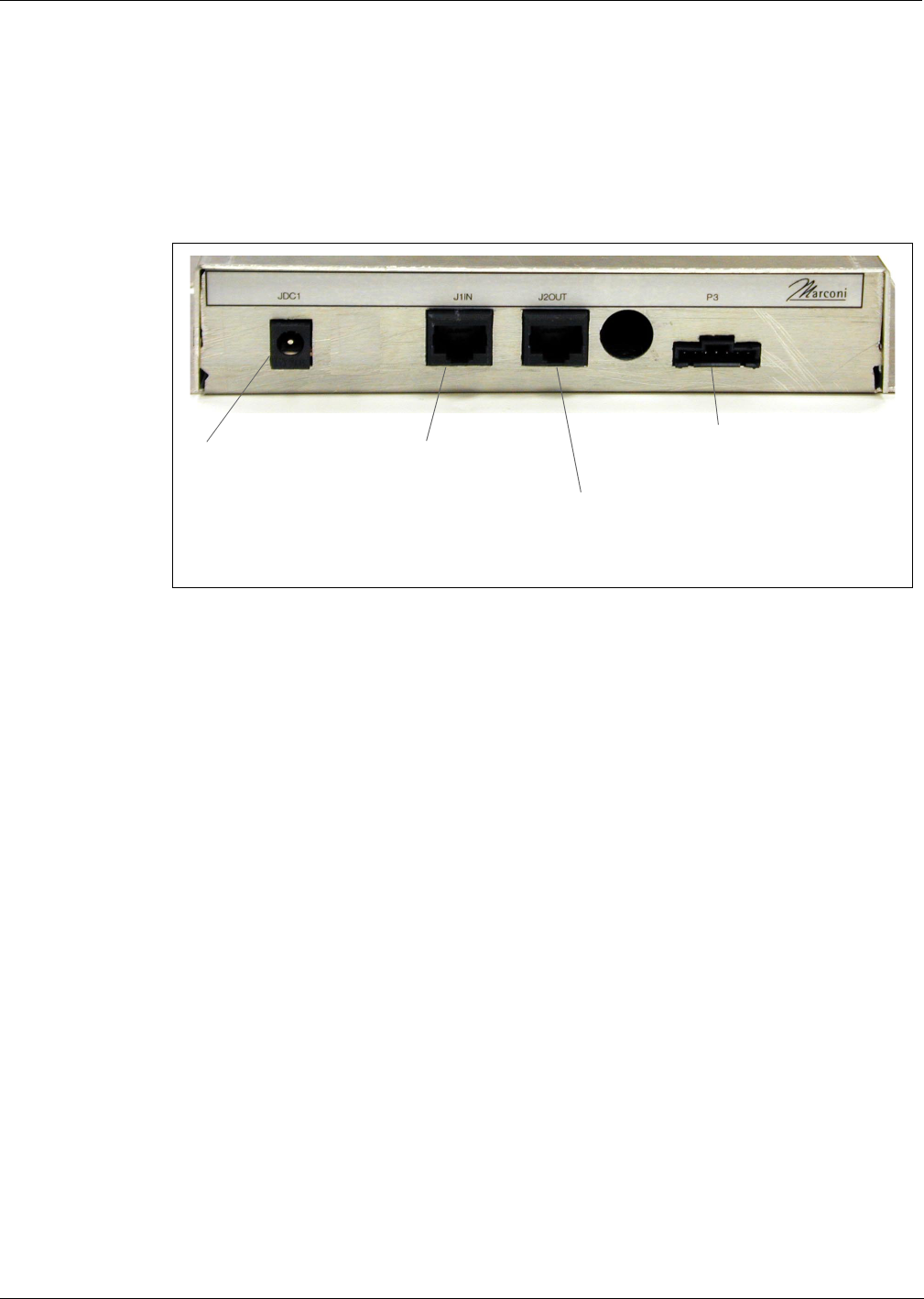
Mounting Mat Reader Interface Box
1Determine the location for the installation of indoor equipment.
Note: Refer to site prep document provided by point of sale company and keep in mind overall
length of cable to connect Mat Reader Interface Box to Mat Reader.
2Use a Zircon stud/bracket finder to ensure no electrical conduits or pipes are located inside of
wall where the Mat Reader Interface Box is to be mounted. Also, ensure the Mat Reader
Interface Box is to be located where studs or wall (concrete/brick/drywall) mollys can be used
for mounting.
3Mark and drill holes. Insert wall mollys as required.
4Use appropriate mounting hardware to secure the Mat Reader Interface Box to the wall.
Figure: Mat Reader Interface Box Mounting Holes
Do not use the Mat Reader Interface Box as a drill guide. It may be used as a template to
mark the holes to be drilled.
CAUTION
mounting holes
Page 9 MDE-4017 TIRIS™ Transmitter/Receiver Mat Reader Assembly Kit C00016-XXX Installation • May 2001
Preliminary
05/24/01
Connecting Data Cables to Mat Reader Interface Box
Run both power and data cables to port end of Mat Reader Interface Box (see “Figure: Mat
Reader Interface Box Mounting Holes” on page 8) as follows.
1Connect the P3 end of the ribbon cable (M01872A001) to the RFID interface port (P3) .
2Connect the J1end of the CAT-5 cable (Q13482-06) to the J1IN port.
Figure: Connecting to Mat Reader Interface Box
Connect power supply here. Connect J1 end of
CAT-5 cable here.
If daisychaining, connect
CAT-5 from J1IN on other
interface box here.
Connect P3 end of
ribbon cable here.
Page 10 MDE-4017 TIRIS™ Transmitter/Receiver Mat Reader Assembly Kit C00016-XXX Installation • May 2001
Preliminary
05/24/01
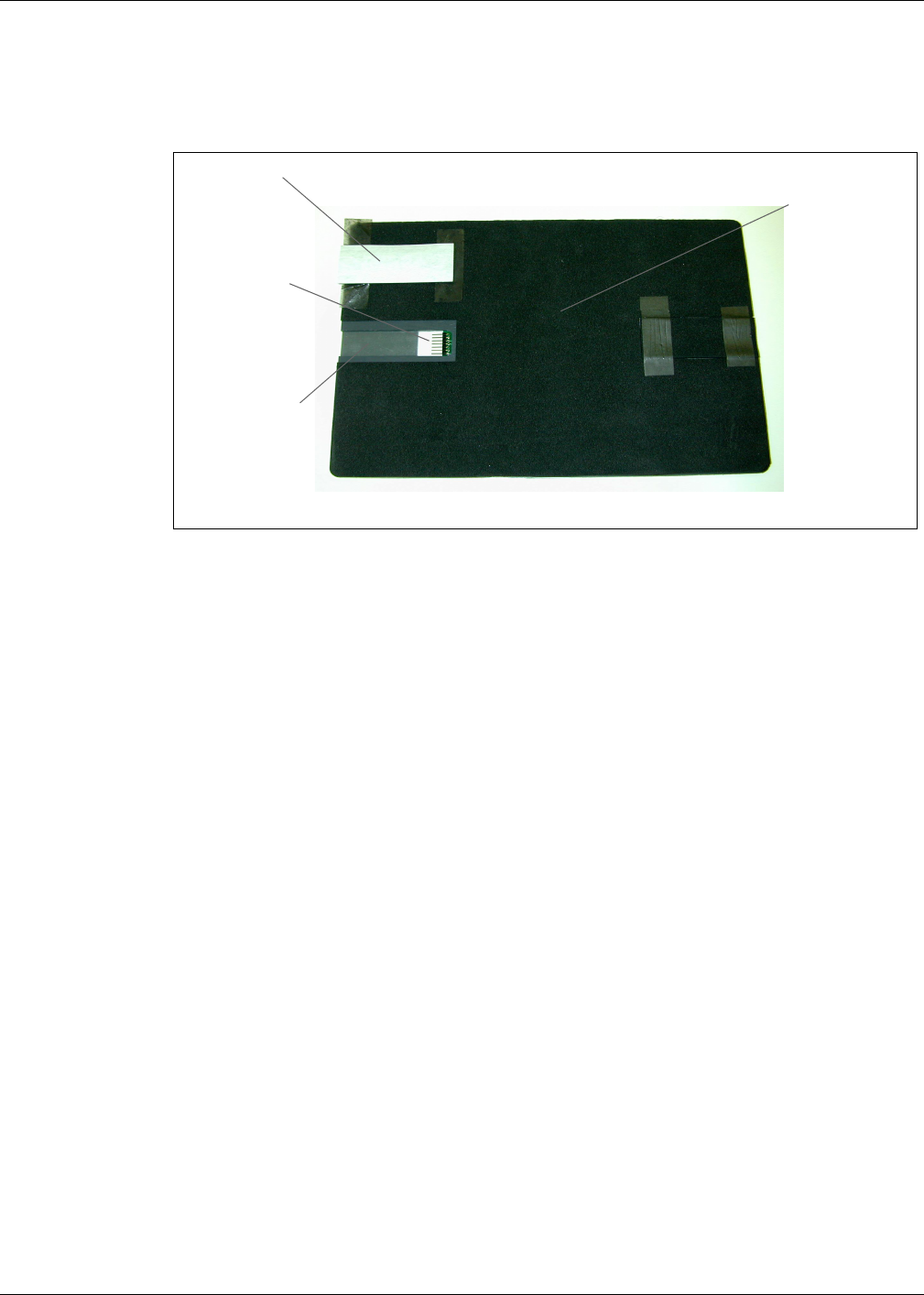
Connecting Data Cables from the Mat Reader Interface Box
1Position Mat Reader face down.
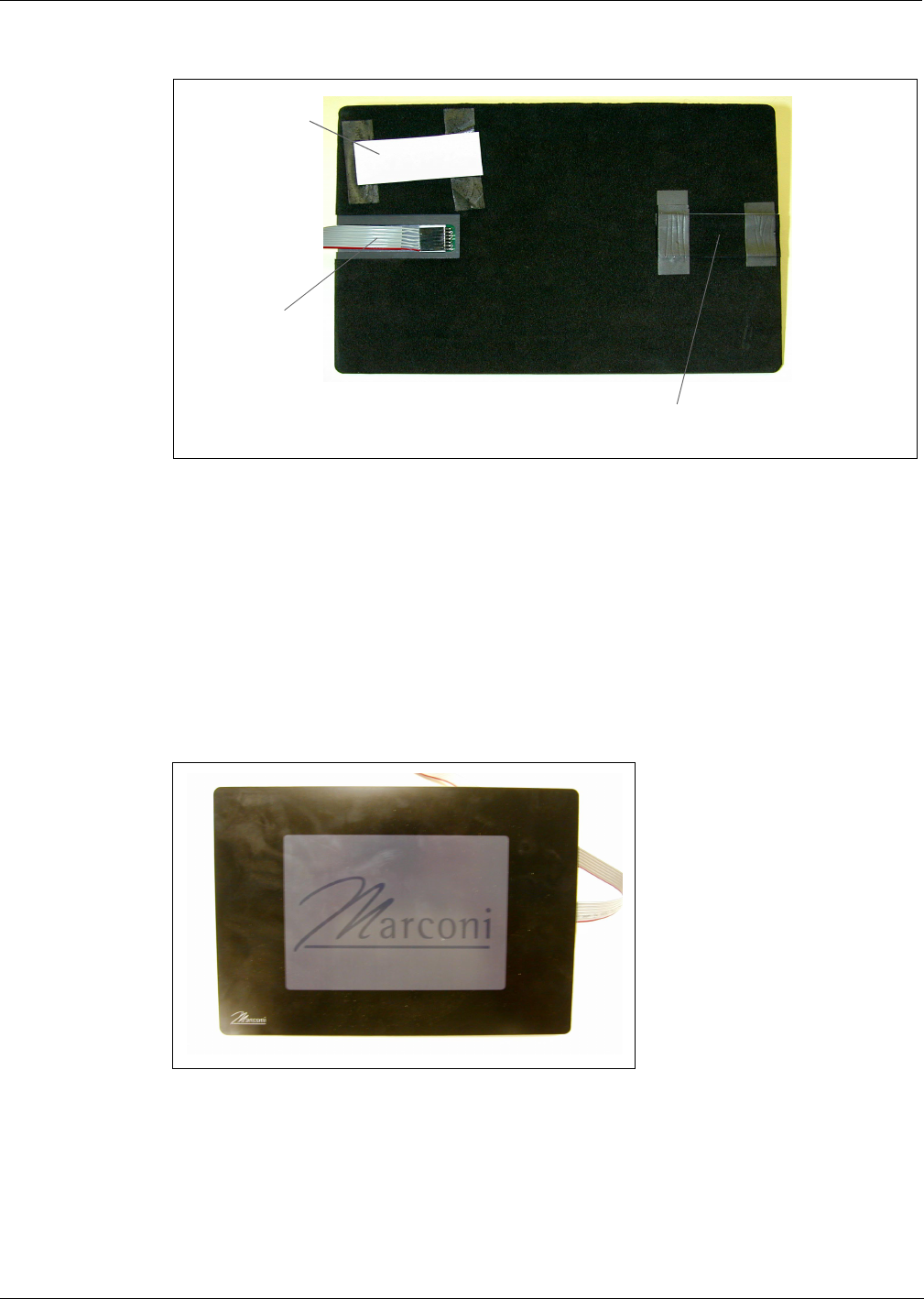
Figure: Bottom Side of Mat Reader
2Select side for ribbon cable (M01872A001) connection based on counter top configuration
requirements.
3Install strip of acrylic foam tape (K85492-72) in base of channel on side selected for ribbon
cable.
4Peel second release liner, exposing adhesive.
5Carefully connect the P1/P2 end of the ribbon cable (M01872A001) to the back side of the
Mat Reader.
Note: The cable can be plugged in from either side. Since the cable is not keyed, the
orientation does not matter. Be sure the cable will be flat and not twisted once the Mat
Reader is face up.
bottom side of
Mat Reader
7-pin connector
channel for ribbon
cable (acrylic foam
tape in place)
bottom side of
neoprene foam
tape (flipped over
to show connector)
Page 11 MDE-4017 TIRIS™ Transmitter/Receiver Mat Reader Assembly Kit C00016-XXX Installation • May 2001
Preliminary
05/24/01
Figure: Connecting to Mat Reader
6Install neoprene foam tape (M01870B001) over ribbon cable and sides of channel. Foam tape
should fit snugly into cutout of surrounding foam tape backer.
7On unused cable channel, install plastic filler channel (M01871B001).
8Install remaining neoprene foam tape (M01870B001) over filler channel. Foam tape should fit
snugly into cutout of surrounding foam tape backer.
9Gently turn the Mat Reader to the face-up position.
Figure: Mat Reader - Face Up
10 Connect the loose end of the CAT-5 cable to the RS-232-1 or RS-232-2 port on the back of the
G-SITE system.
Note: The exact G-SITE system port depends on the G-SITE system configuration.
ribbon cable
connected to 7-
pin connector
unused channel filled with plastic filler channel
and covered by neoprene foam tape
bottom side of
neoprene foam tape
Page 12 MDE-4017 TIRIS™ Transmitter/Receiver Mat Reader Assembly Kit C00016-XXX Installation • May 2001
Preliminary
05/24/01
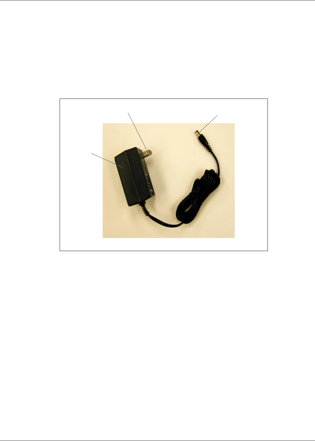
Connecting Power Supply
Connect the power supply (M01878B001) provided with kit as shown.
1Plug the wall-mounted transformer into the AC power outlet.
Note: This AC power outlet must be on the same circuit as the G-SITE system.
2Connect the plug end of the power supply cable to the JDC1 port on the Mat Reader Interface
Box (see “Figure: Connecting to Mat Reader Interface Box” on page 9).
Figure: Power Supply (M01878B001)
wall-mounted
transformer
plugs into JDC1 port
plugs into AC power outlet
Page 13 MDE-4017 TIRIS™ Transmitter/Receiver Mat Reader Assembly Kit C00016-XXX Installation • May 2001
Preliminary
05/24/01
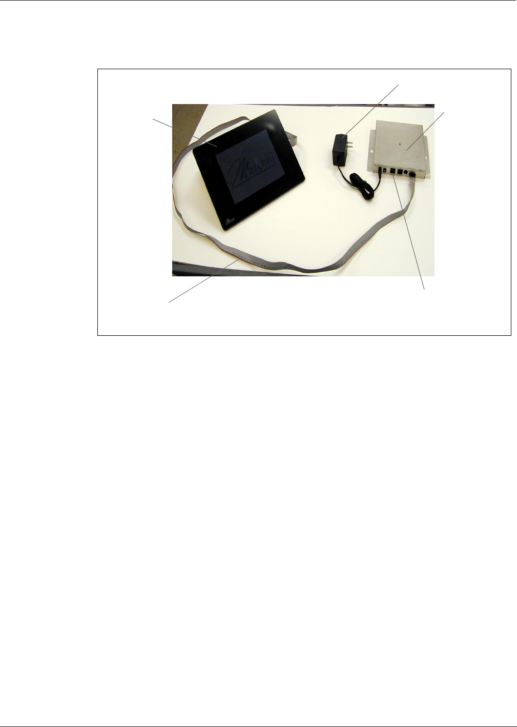
Completing Installation
Figure: Mat Reader Connections
1Dress all cables and secure with stick on cable clamps (Q13459-01).
2Clean up the work area.
3Go to “Commissioning and Warranty Information” on page 14.
CAT-5 cable
connects here
power supply
interface box
Mat Reader
ribbon cable

© 2001 Marconi Commerce Systems Inc.
7300 West Friendly Avenue • Post Office Box 22087
Greensboro, North Carolina 27420
Phone (336) 547-5000 • http://www.marconicommerce.com • Printed in the U.S.A.
MDE-4017 TIRIS™ Transmitter/Receiver Mat Reader Assembly Kit C00016-XXX Installation • May 2001
Preliminary
05/24/01
Commissioning and Warranty Information
Upon completion and testing the Mat Reader system, the installing contractor must call the
Marconi Commerce Systems Call Center @ 1-888-800-7498 to register the installation and
activate the warranty. Note the installed unit’s full Model Number (C00016-XXX) and serial
number before making this call.
•All Mat Readers have a one-year parts only warranty.
Note: Parts are to be returned through and obtained from the local Marconi distributor.
•Labor warranty, if any, is unit and customer specific.
Marconi Commerse Systems strongly recommends using only Marconi trained ASCs
(Authorized Service Contractors) to perform service on the units. Use of non-authorized
service personnel to repair or service these units may void warranty. Call your local distributor
for service.
TRIND® is a registered trademark of Marconi Commerce Systems Inc.
Phillips® is a registered trademark of Phillips Screw Company.
UL® is a registered trademark of Underwriters’ Laboratories, Inc.
Zircon® is a registered trademark of Zircon International Inc.