Gilbarco MRIR2 Radio Frequency Identification device User Manual
Gilbarco Inc. Radio Frequency Identification device
UserManual.wiki
>
Gilbarco
>
MRIR2 User Manual
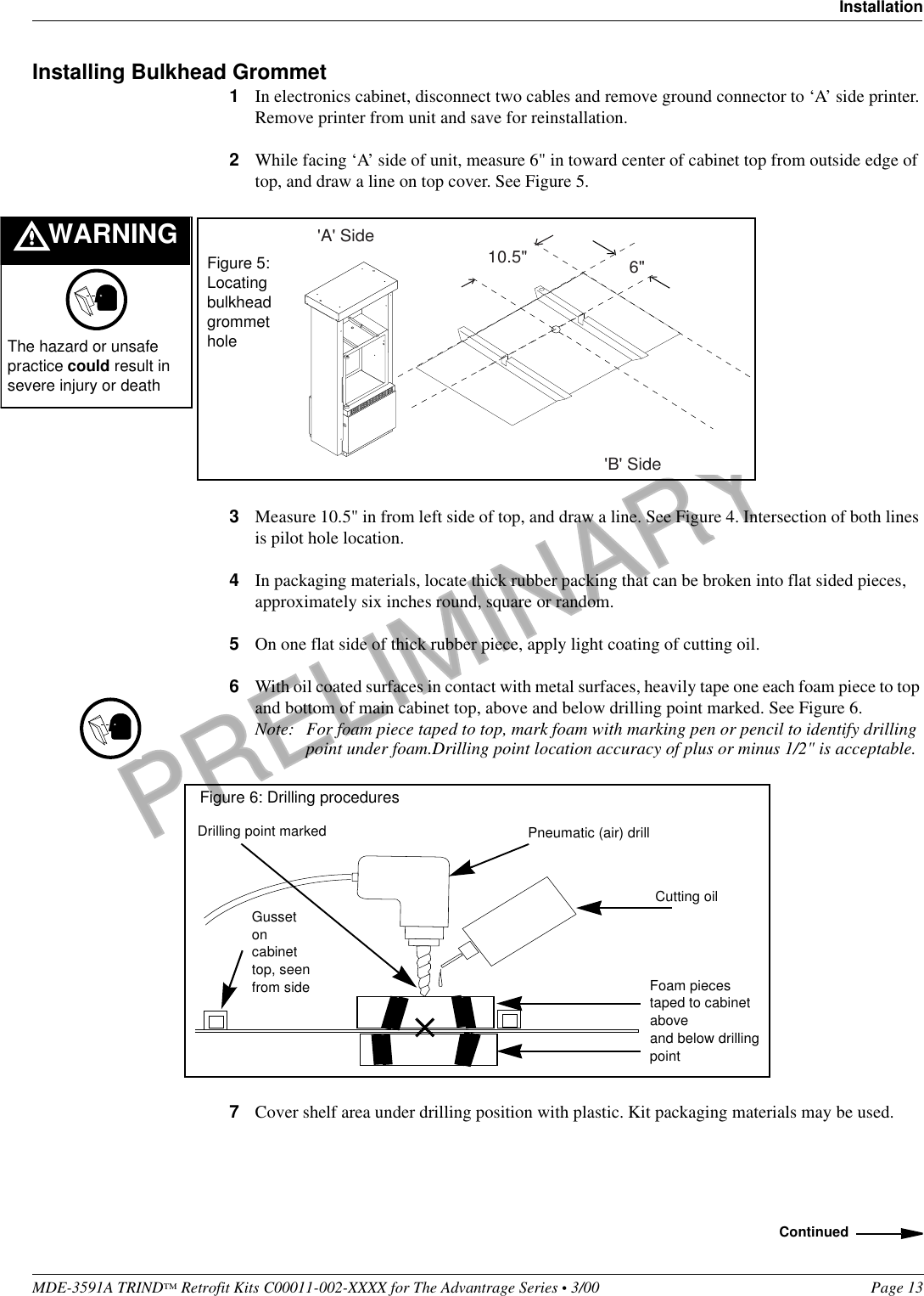
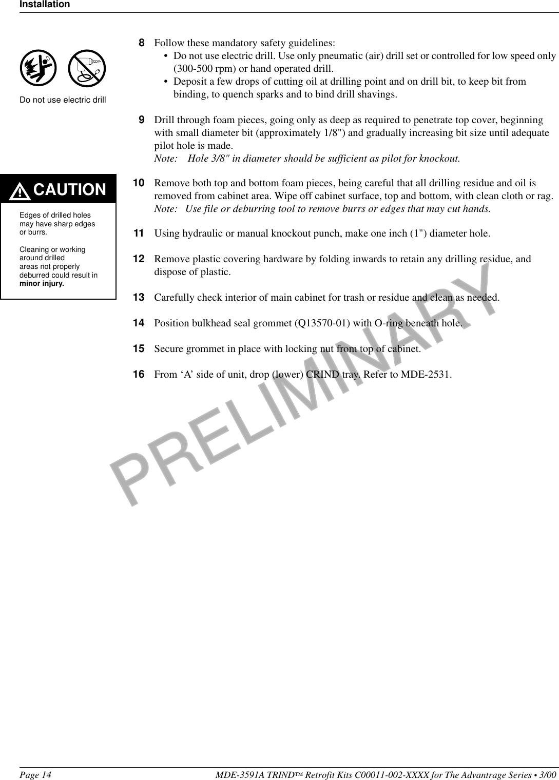
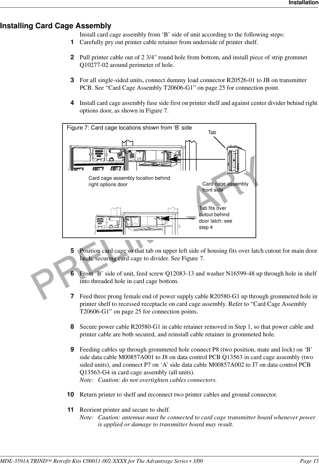
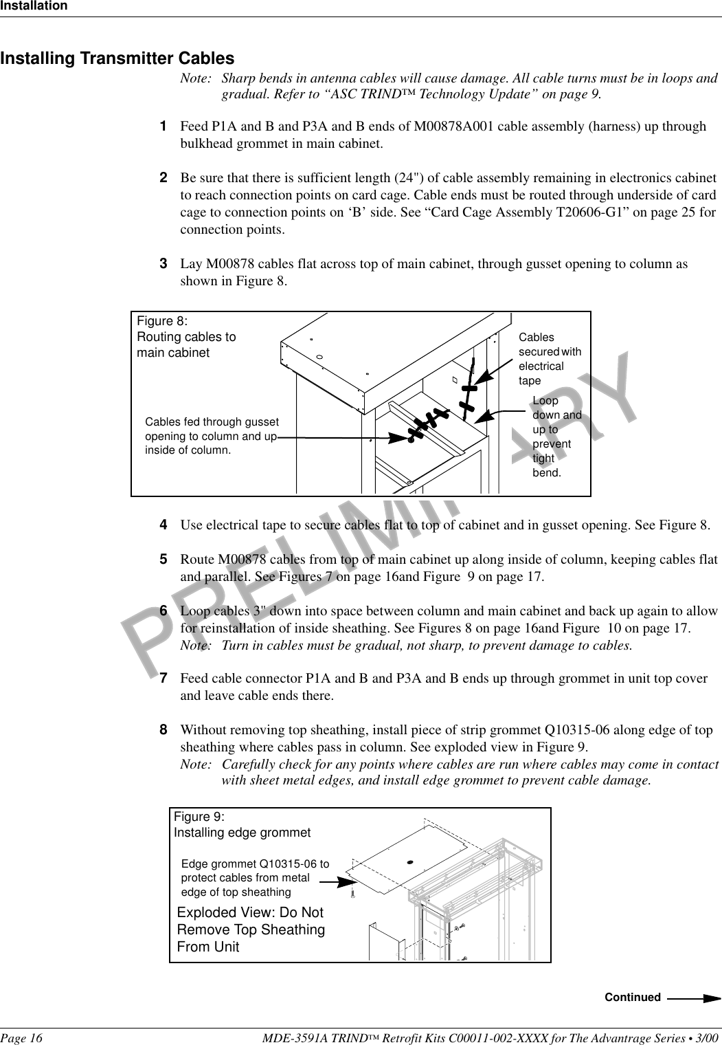
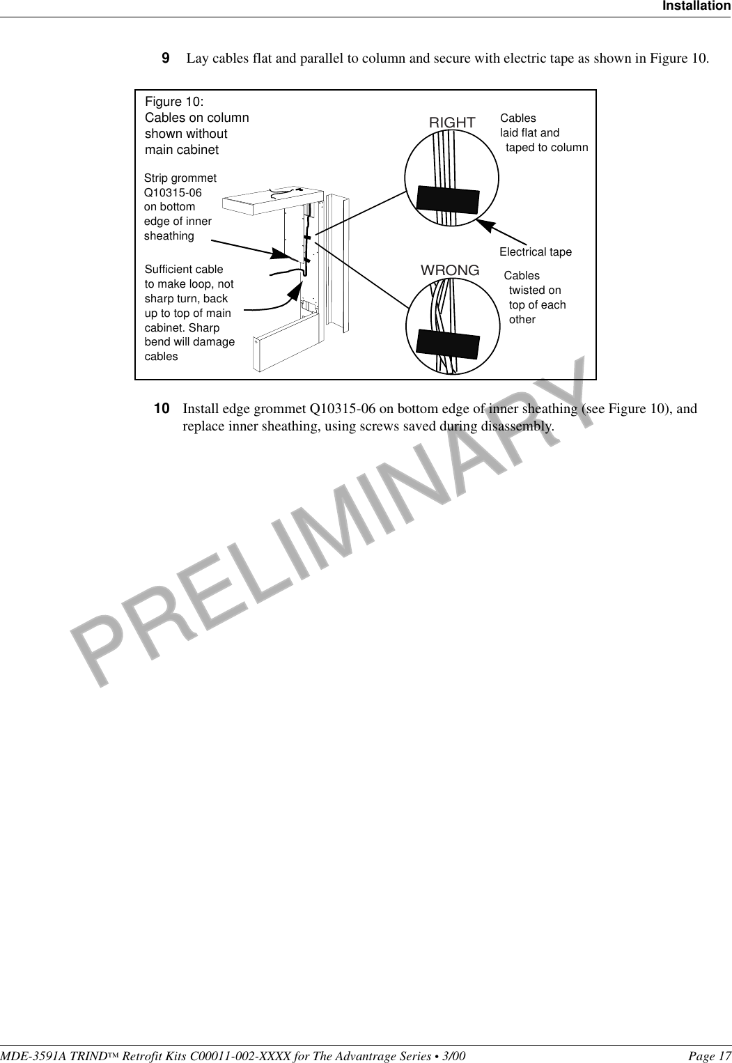
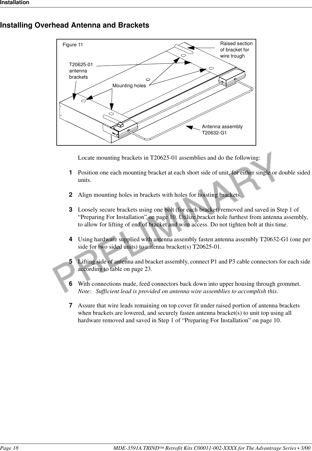
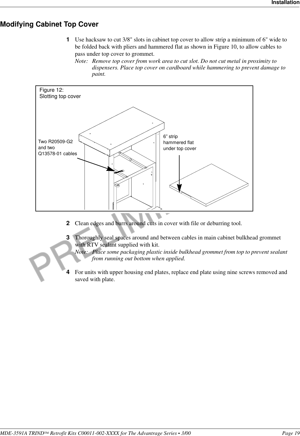
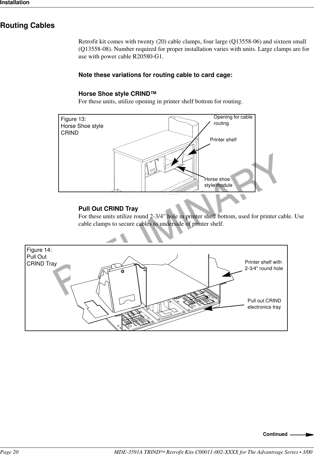
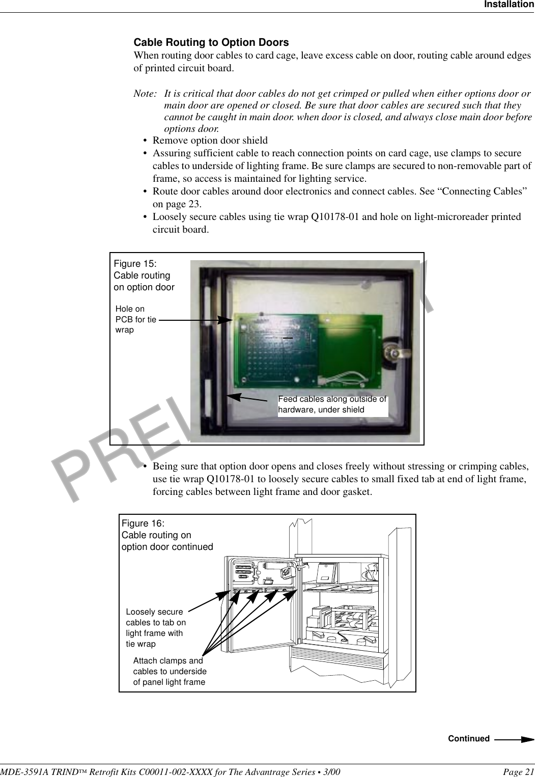
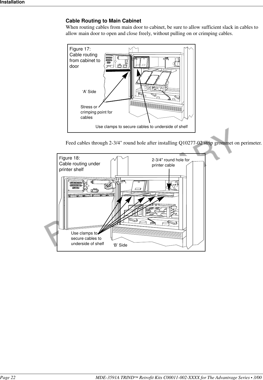
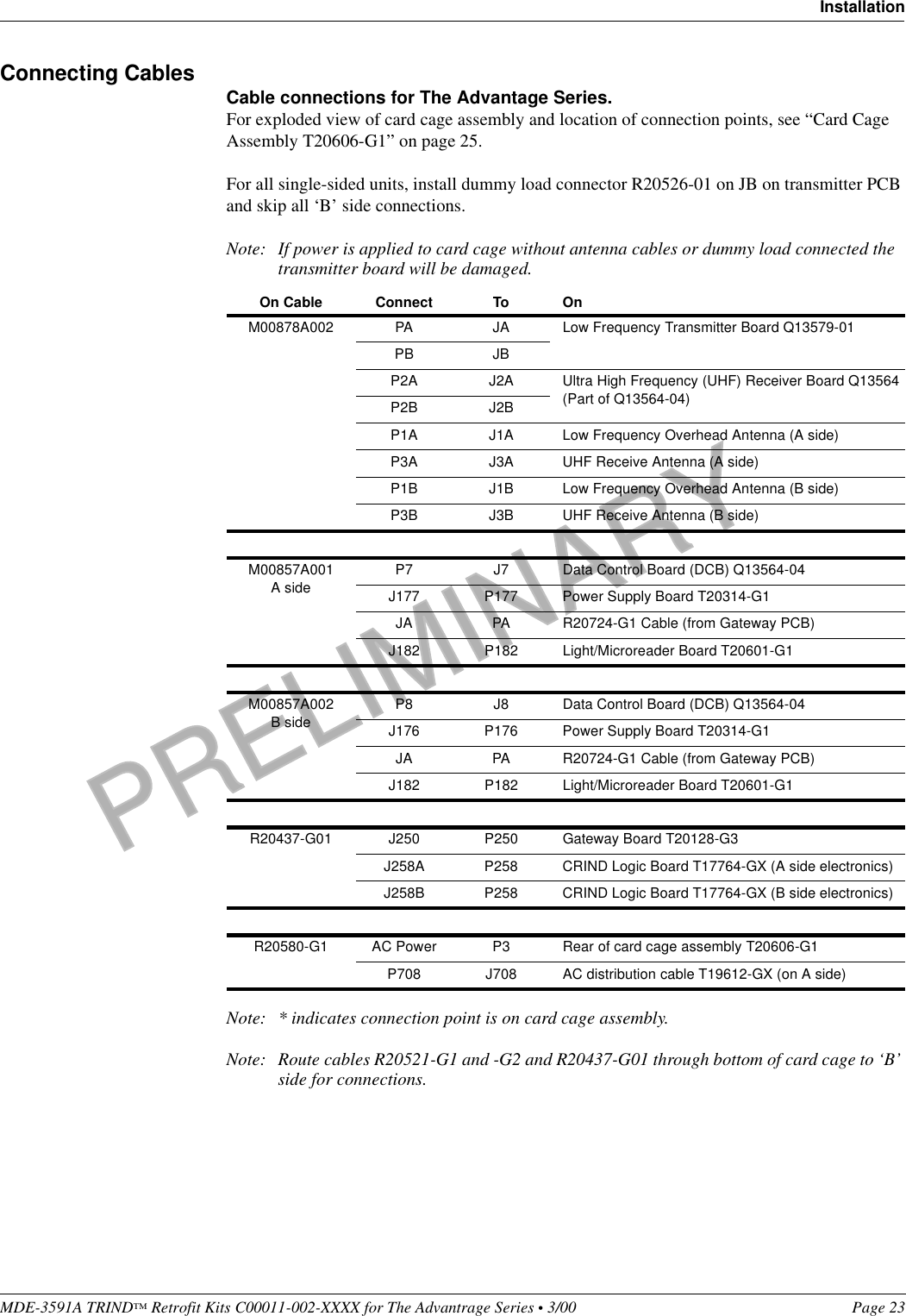
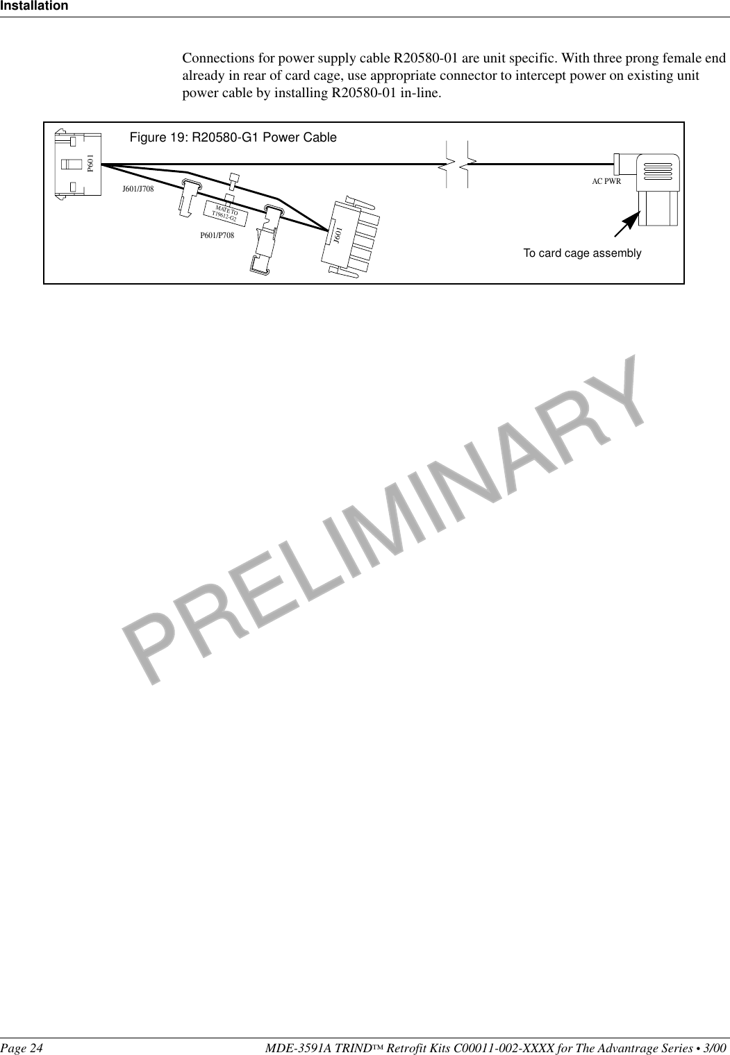
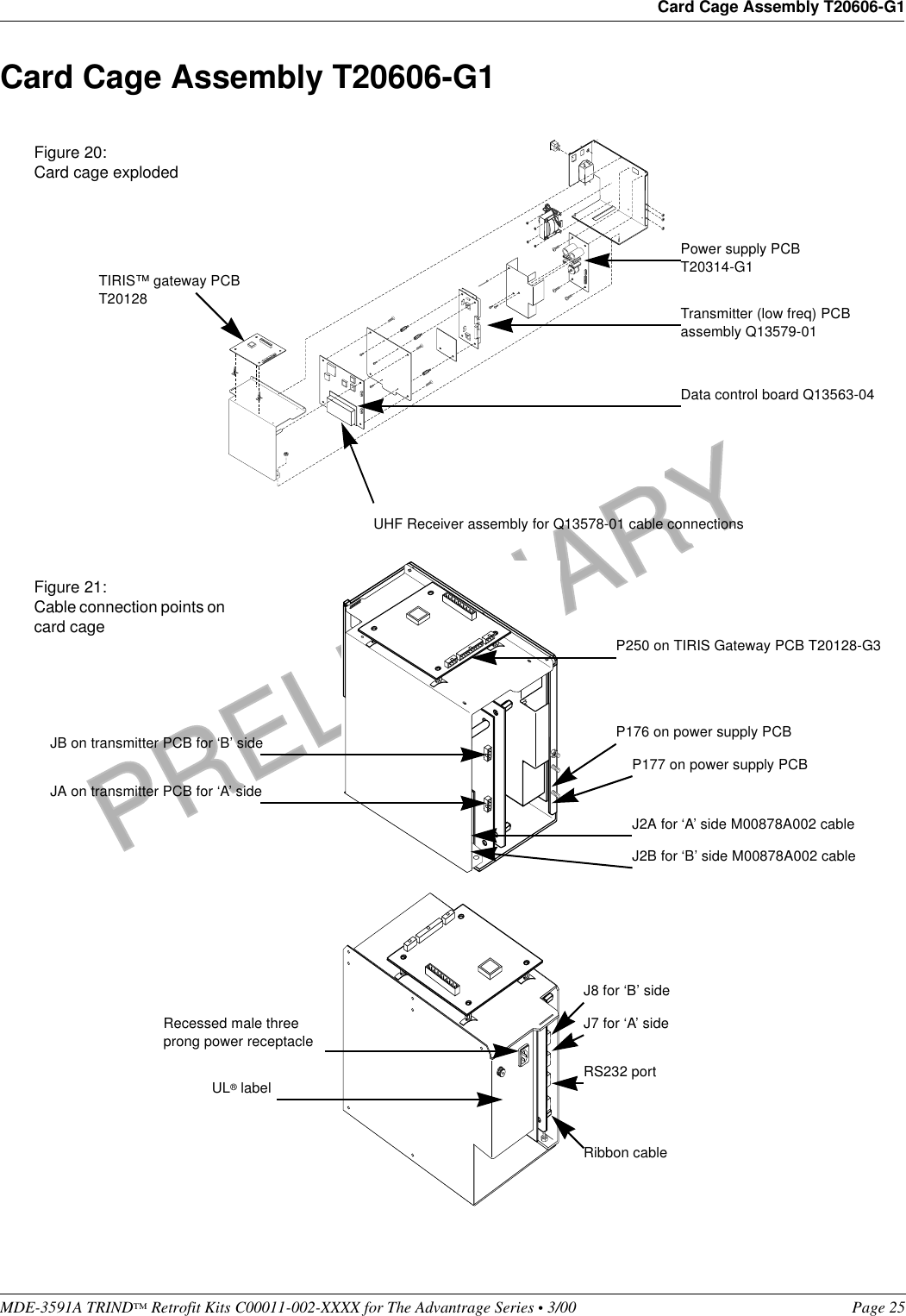
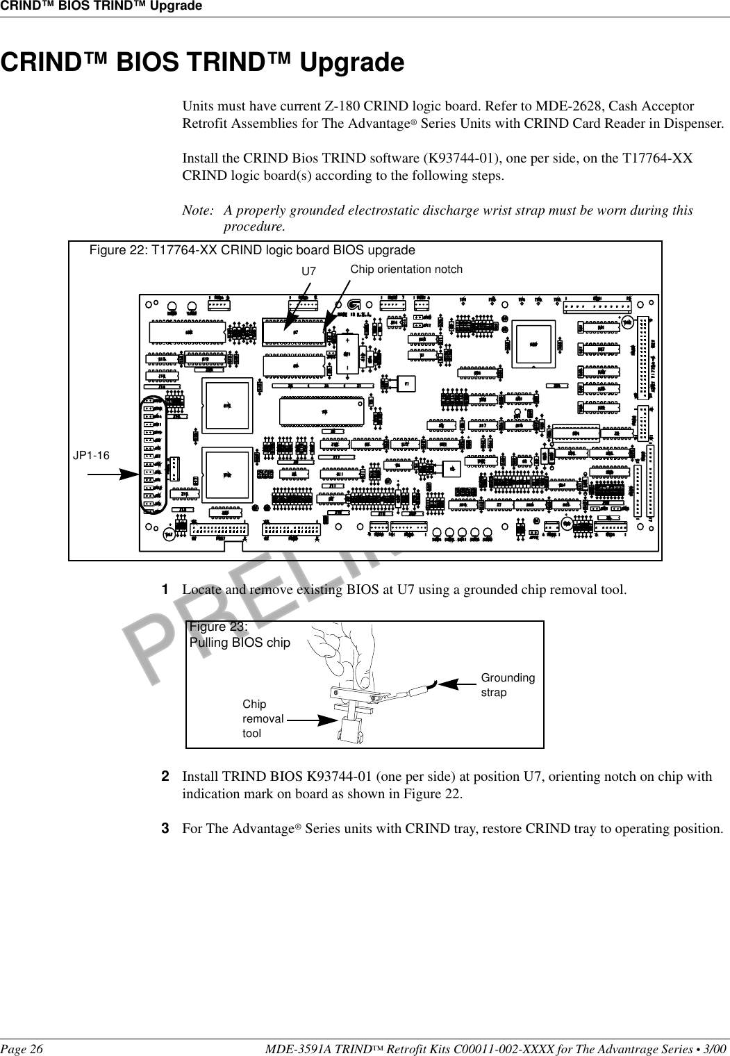
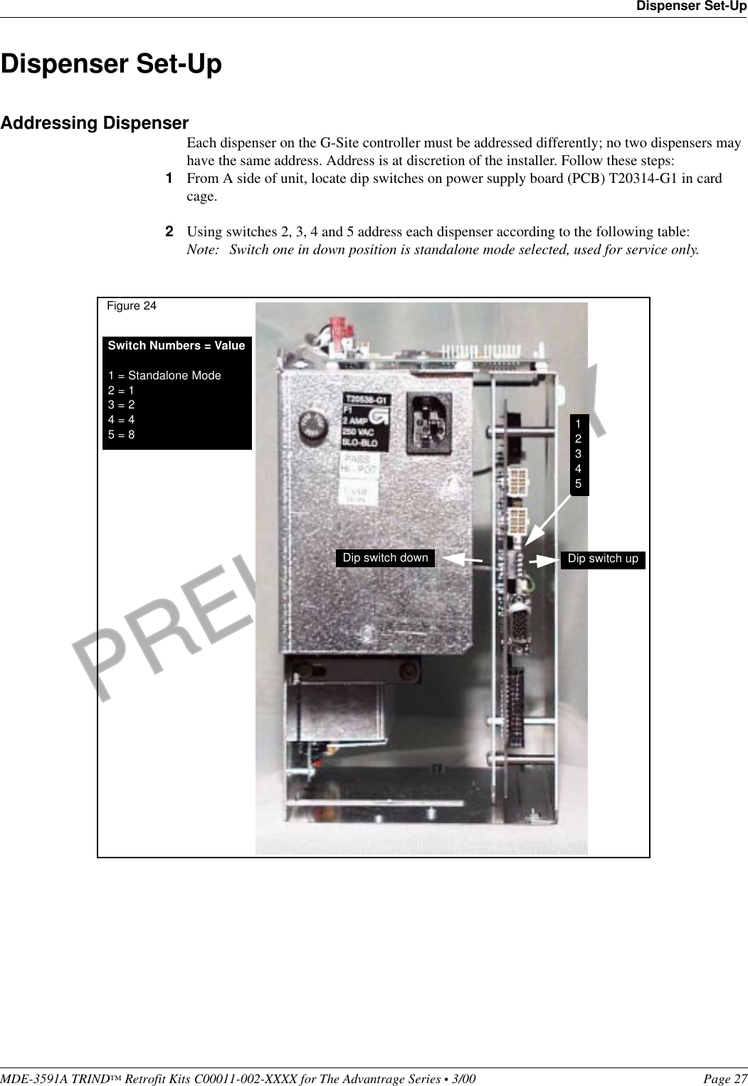
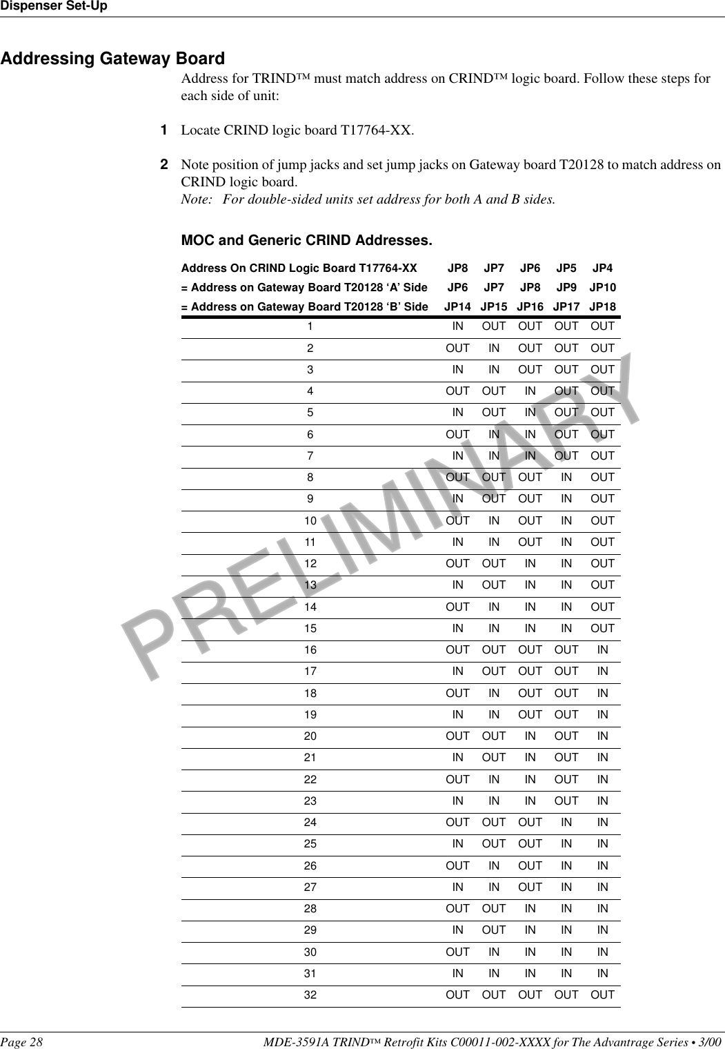
Installation Manual
Navigation menu
Upload a User Manual
Namespaces
Wiki Guide
HTML
PDF
Info
Views
User Manual
Discussion / Help
Navigation