Gilbarco MRIR2 Radio Frequency Identification device User Manual
Gilbarco Inc. Radio Frequency Identification device
Gilbarco >
Installation Manual

PRELIMINARY
MDE-3591A TRIND™ Retrofit Kits C00011-002-XXXX for The Advantrage Series • 3/00 Page 1
Introduction
Purpose of this Manual
This manual provides instruction for installing TRIND™/TIRIS™ Retrofit Kits
C00011-002-XXXX in The Advantage® Series wide frame units with InfoScreen®,
monochrome CRIND™, or single-line CRIND.
The TRIND option allows customers to automatically authorize CRIND-equipped units, using
either a hand-held or auto-mounted transponder provided by a major oil company (MOC). Use
these kits for one- or two-sided units.
Retrofit Kits C00011-002-XXXX are configured according to specific unit requirements.
Prerequisites Before installing any TRIND kit, ensure that the existing CRIND contains the following.
• Z-180 logic board and software (T17764-XX), which is not configured in TRIND retrofit
kit. Refer to MDE-2628, Cash Acceptor Retrofit Assemblies for The Advantage Series
Units with CRIND Card Reader in Dispenser Kit C00007-002.
• Plastic options doors for single-line/cash acceptor InfoScreen/cash acceptor and
monochrome/cash acceptor
Important Notice This equipment has been tested and found to comply with the limits for a Class A digital
device pursuant to Part 15 of the FCC Rules. These limits are designed to provide reasonable
protection against harmful interference when the equipment is operated in a commercial
environment. This equipment generates, uses and can radiate radio frequency energy, and if not
installed and used in accordance with the instruction manual, may cause harmful interference
to radio communications. Operation of this equipment in a residential area is likely to cause
harmful interference in which case the user will be required to correct the interference at his
own expense. Changes or modifications not expressly approved by the manufacturer could
void the user’s authority to operate this equipment.
Required Reading Before installing the equipment, the installer must read, understand, and follow:
•this manual
• NFPA 30A, The Automotive and Marine Service Station Code
• NFPA 70, The National Electric Code
• applicable federal, state and local codes and regulations
• ASC TRIND Technology Update on page 9
Failure to do so may adversely effect the safe use and operation of the equipment.
Note: These kits must be installed by a Gilbarco ASC (Authorized Service Contractor)
MDE-3591A
TRIND™ Transmitter/Receiver in Dispenser
Retrofit Kits C00011-002-XXXX
Using TIRIS™ Technology
Installation

PRELIMINARY
Introduction
Page 2 MDE-3591A TRIND™ Retrofit Kits C00011-002-XXXX for The Advantrage Series • 3/00
Related Documents MDE-2531 Pump & Dispenser Start-Up & Service Manual
MDE-2562 CRIND Service Manual
MDE-2628 Cash Acceptor Retrofit Assemblies for The Advantage Series with CRIND
MDE-2620 Graphics Panel Application for The Advantage Series
MDE-3640 Authorized Service Contractor (ASC) TRIND Installation Tool Kit K94577-01
PT-1728 The Advantage Series Illustrated Parts Manual
PT-1736 CRIND Card Reader Illustrated Parts Manual
Required Tools The following equipment is needed to install TRIND™ kit C00011-002
• Allen wrench set, American standard
• clean cloth or rag
• chip extraction tool, e.g., IC extraction, Digikey Part No. K158-ND or equivalent
• isopropyl alcohol (part# END-1082)
• ladders, style ‘A’, quantity of two (2)
•multimeter
• pencil or marker
•pliers
• pocket knife
• putty knife or scraper
• Q12534 CRIND diagnostic card
• ratchet set, standard
• screwdrivers, flat and Phillips head
• static guard wrist strap
• straight edge, 24"
• TRIND ASC tool kit (See “ASC TRIND™ Tool Kit K94577-01” on page 3 and refer to
MDE-3640, ASC TRIND Installation Tool Kit K94577-01)
• work bench or saw horses (packaging cartons may be used as bench)

PRELIMINARY
MDE-3591A TRIND™ Retrofit Kits C00011-002-XXXX for The Advantrage Series • 3/00 Page 3
Parts Lists
Parts Lists
C00011-002-XXXX Kit Configurations by Suffix
Common Parts for All C00011-002-XXXX Kits
ASC TRIND™ Tool Kit K94577-01
-Suffix Configured For See
-WF_S The Advantage® Series 48" (wide frame) single-sided page 4
-WF_D The Advantage Series 48" (wide frame) double-sided page 4
Description Assembly Contains Part Number Quantity
cable clamp, gray Q13558-04 16
cable clamp, gray Q13558-06 4
cable group assembly
(parts shown in columns at right) Q13863-01 1
cable, TRIND to CRIND R20437-G01 1
cable, TRIND AC power R20580-G1 1
cable, light/multi-protocol M00857A001 1
cable, light/multi-protocol M00857A002 1
cable, antenna/low frequency M00878A002 1
card cage assembly T20606-G1 1
grommet, edge Q10315-06 1.5 ft.
grommet material, strip Q10277-02 1 ft.
jump jack Q11011-01 10
label plate, FCC N23949-01 1
nut, Keps Q12068-03 2
screw, sems, 6-32 x 3/8 Q12083-13 1
screw, 8-32 x 3/8 Q12083-26 2
silicone sealant, RTV, tube END 1576 1
software, CRIND™ Bios TRIND K93744-01 1
tie wrap Q10178-01 4
washer, flat N16599-48 1
Tool Description Part Number Quantity
co-axial cable tool Q13628-01 1
field strength sensor Q13626-01 1
test tag, TI/RFIDcar mount Q13630-01 1
test tag, TI/RFID hand held Q13630-02 1
threaded rod, 3/8-16 x 4" N23880-01 4
tuning tool, plastic tipped Q13631-01 1

PRELIMINARY
Parts Lists
Page 4 MDE-3591A TRIND™ Retrofit Kits C00011-002-XXXX for The Advantrage Series • 3/00
C00011-002-WF S
For The Advantage® Series 48" (wide frame) single-sided units.
Kit contains all parts from “Common Parts for All C00011-002-XXXX Kits” on page 3 plus
the following.
C00011-002-WF D
For The Advantage® Series 48" (wide frame) double-sided units.
Kit contains all parts from “Common Parts for All C00011-002-XXXX Kits” on page 3 plus
the following.
Description Part Number Quantity
antenna assembly T20632G1 1
bracket assembly, antenna mounting T20625-01 2
gasket, 1/2" x 1/16" strip Q11899-12 1.5 ft.
grommet, bulkhead seal Q13570-01 1
grommet, round N15941-38 4
load connector, dummy transmitter R20526-G1 1
option door assembly T20613-G1 1
screw, 10-32 black K85736-45 14
Description Part Number Quantity
antenna assembly T20632G1 2
bracket assembly, antenna mounting T20625-01 2
gasket, 1/2" x 1/16" strip Q11899-12 3 ft.
grommet, bulkhead seal Q13570-01 1
grommet, round N15941-38 4
option door assembly T20613-G1 2
screw, 10-32 black K85736-45 16

PRELIMINARY
MDE-3591A TRIND™ Retrofit Kits C00011-002-XXXX for The Advantrage Series • 3/00 Page 5
Safety Information
Safety Information
Alert Symbol and Signal Words
Alert Symbol:
This is a standard ANSI* approved alert symbol. When you see this symbol, be alert to the
potential for a personal injury.
* Reference American National Standard Bulletins ANSI Z535.
Signal Words:
These signal words alert you to important safety hazards.
Safety Symbols: The following safety symbols are used throughout this manual to alert you to personal safety
hazards and precautions.
Explosive
Flammable
Electrical hazard
Use safety barricades
No people in area
No vehicles in area
Use emergency power disconnect
No open flames
No smoking
No power tools
Wear eye protection
Read all related manuals
Clean up spills
Turn power off
!
WARNING
The hazard or unsafe
practice may result in
severe injury or death.
!
CAUTION
The hazard or unsafe
practice could result in
minor injury.
The hazard or unsafe
practice will result in
severe injury or death.
!
DANGER
OFF
PRELIMINARY
Safety Information
Page 6 MDE-3591A TRIND™ Retrofit Kits C00011-002-XXXX for The Advantrage Series • 3/00
Before Beginning Do the following:
Read all instructions before beginning.
Follow all safety precautions, including:
• Barricade work area.
• Do not allow vehicles or unauthorized people in work area.
• Do not use power tools in work area.
• Do not permit smoking or open flames in work area.
• Wear protective gear while performing this installation.
Record all mechanical and electronic totals.
Turn off all power to unit, unit lights and STPs.
• Use system circuit breakers.
• Multiple disconnects may be required.
• Isolate each pump at distribution box.
• Refer to MDE-2531, Pump and Dispenser Start-up and Service for OSHA
lock-out/tag-out procedures.
When system battery is present, turn off system battery by pressing CLEAR then ENTER on
manager keypad.
WARNING
!
Dangerous Environment! Failure to
install this equipment in accordance
with NFPA 30A and NFPA 70 could
result in severe injury or death.
Read, understand and follow NFPA
30A and NFPA 70.
OFF
WARNING
Working on dispenser
electronics with power
applied may result in
electrocution and
damage to electronic
components.
Power down unit before
beginning work.
OFF
!

PRELIMINARY
MDE-3591A TRIND™ Retrofit Kits C00011-002-XXXX for The Advantrage Series • 3/00 Page 7
Safety Information
Use Electrostatic Discharge Precautions
Place yourself at a neutral static-free potential by doing the following:
1Touch an unpainted metal surface.
2Use a wrist strap connected to a grounded metal frame or chassis.
Note: Failure to use electrostatic discharge precautions may damage electronic components
and void warranty.
Make sure all power has been removed from unit and CRIND.
Follow OSHA Lock-Out and Tag-Out Requirements
OSHA Standard 29 CFR 1910-147 Control of Hazardous Energy Sources (Lock-Out/Tag-Out)
covers ways to avoid personal injury if power is turned on or fuel pressure is applied
unexpectedly while servicing equipment. The rule requires that equipment power and fuel
under pressure be turned off and the device (breaker, valve, etc.) locked or labeled with a
warning tag.
Read OSHA Standard 29 CFR 1910-147 Control of Hazardous Energy Sources (Lock-Out/
Tag-Out). Station employees and service contractors need to understand and comply with this
program completely to ensure safety while the equipment is down.
Tag-Out and Lock-Out Procedure
Use plastic warning tags with signature/date blanks for Tag-Out. Sign and date them at shut
down. Attach tags with plastic connectors.
Use metal screw-down lock clamps or plastic single or multi-pole devices for Lock-Out of
breakers and switches. Always use a lock-out device whenever possible.
When working on electronics and electrical connections (junction box):
• Turn off unit power, light breakers, and all dispensers sharing the same isolation relay box.
• Install lock-out device and tag on breaker(s).
Note: If station does not use STP control wire isolation relays, multiple disconnects may be
required to shut off all power supplied to the unit.
OFF

PRELIMINARY
Classifying Hazardous Locations
Page 8 MDE-3591A TRIND™ Retrofit Kits C00011-002-XXXX for The Advantrage Series • 3/00
Classifying Hazardous Locations
Any activity that can cause an explosion (such as smoking or drilling) must be done well
outside the vapor area.
The following diagram is based on NFPA 30A, section 6 and NFPA 70, section 514.
Fuel is present.
(Flammable Liquid)
Class 1 Division 2
(Hazardous Location)
Class 1 Division 1
(Hazardous Location)
Fuel Containing
Components
Vapor Areas
18"
18"
Unclassified location
area within electronics cabinet
above Air Gap.
Class 1 Division 1
within boot area.
Air Gap
20'
Pit box.
20'
20'
20'
Vertical Vapor Barrier
S0001866

PRELIMINARY
MDE-3591A TRIND™ Retrofit Kits C00011-002-XXXX for The Advantrage Series • 3/00 Page 9
ASC TRIND™ Technology Update
ASC TRIND™ Technology Update
The TRIND™ system utilizes technology and devices not commonly used in the industry.
Read the following carefully to familiarize yourself with relatively unique aspects of TRIND
and prevent field problems.
RF Transmission and Antennas
Located in the TRIND card cage is a transmitter printed circuit board (PCB). The RF antennas
are connected to this board during installation.
Applying power to the card cage with either antenna disconnected will result in damage
to the transmitter PCB.
• The transmitter PCB may be burned up immediately, or its effective life shortened
drastically.
• The PCB may perform properly at installation, but will require premature field service at a
later date.
For single-sided units, a ‘dummy load’ connector R20526-G1 is provided for unused ‘B’ side
of the PCB.
Note: Power must never be applied to the card cage without a load, either antennas or
dummy load connector.
Co-Axial Cable
Co-axial antenna cables Q13756-01, part of cable assembly M00878, used for TRIND are
more flexible and smaller diameter than more familiar co-axial cable, such as that used for
cable television. However, all co-axial cables share this feature:
Too severe a turn or bend in the cable will break the center (solid) wire.
This can result in a seemingly good but in actuality intermittent signal. This too may result in
what appears to be proper performance at installation that is followed by premature failure and
field service. Replacing damaged cable in the field is an extensive task.
In addition, a damaged cable will also cause a situation where the transmitter PCB is powered
without load, and damage the PCB.
Note: Turns or bends in co-axial cables Q13556-01 must be gradual loops, no sharper than a
1" radius (2" diameter).
For installation instructions, proceed to page 10.
ATTENTION: AUTHORIZED SERVICE CONTRACTORS
READ THIS SECTION BEFORE PROCEEDING WITH INSTALLATION

PRELIMINARY
Installation
Page 10 MDE-3591A TRIND™ Retrofit Kits C00011-002-XXXX for The Advantrage Series • 3/00
Installation
Before beginning read “Safety Information” on page 5.
Preparing For Installation
Perform these steps for all The Advantage® Series units
1Remove four hoisting brackets from top of unit by removing four bolts and washers. Dispose
of hoisting brackets. Save hardware for reassembly.
Note: On units with logo display cabinet, hoisting brackets have already been removed.
2From ‘A’ side of unit, remove inner sheathing on left column. Set sheathing and screws aside
for reassembly.
3Open main access doors. Refer to MDE-2531, Pump and Dispenser Start-Up/Service Manual
for access instructions.
4Remove cabinet top cover from main panel by accessing mounting hardware from inside main
cabinet. See Figure 2. Save top cover and fastening hardware for reassembly.
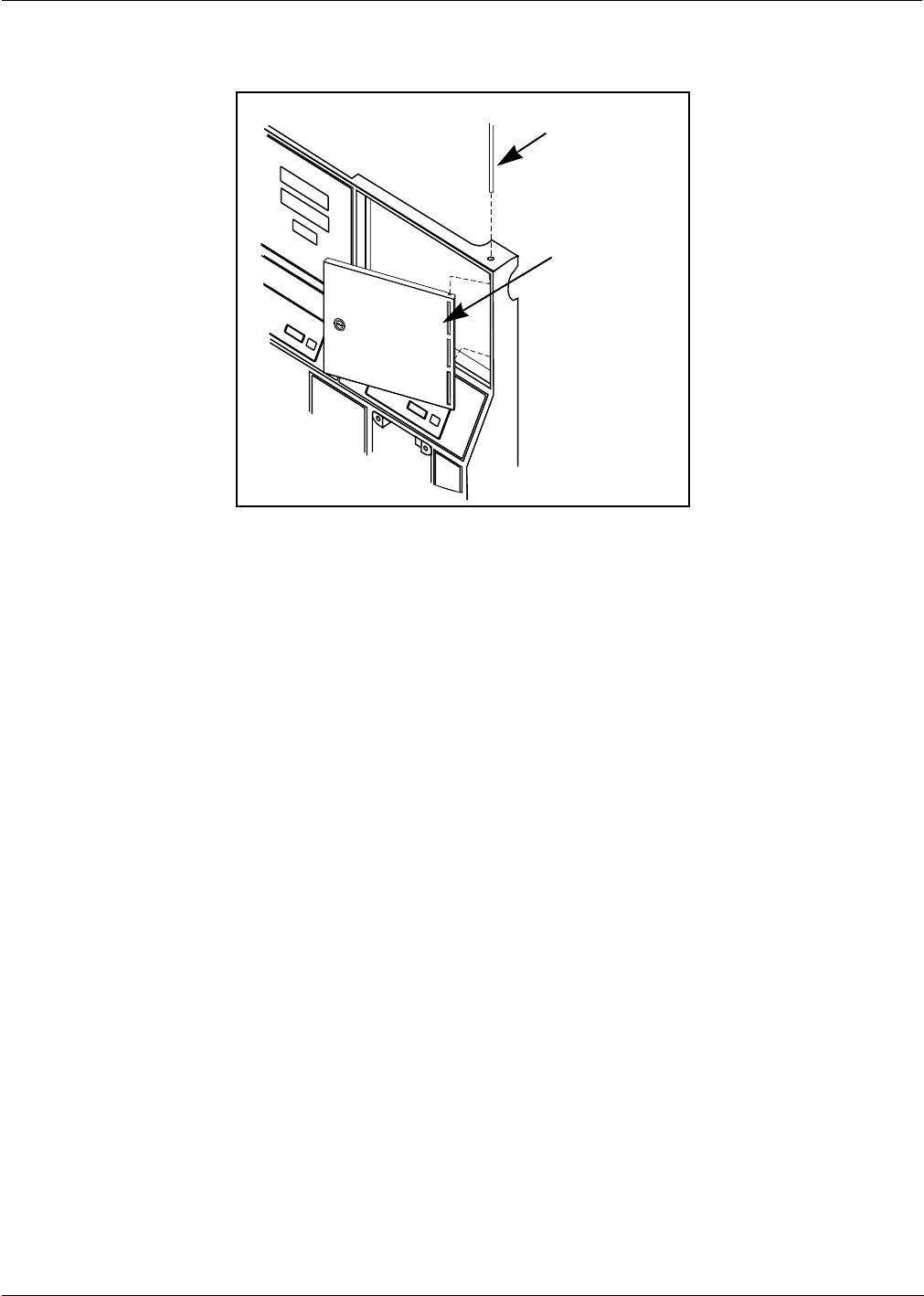
5Remove door mounting pin and right options door. See Figure 3.
S0000750
Hoisting brackets
and 3/8” bolts
Figure 1:
Removing hoisting
brackets
Top cover
Access to top cover
fastening bolts from
inside main cabinet
Figure 2:
Removing
cabinet
top cover
Continued
PRELIMINARY
MDE-3591A TRIND™ Retrofit Kits C00011-002-XXXX for The Advantrage Series • 3/00 Page 11
Installation
6Dispose of door. Save pin for reassembly.
Removing Knockout on Top Cover
1Remove knockout from left side of unit top cover while facing ‘B’ side for single sided units,
or both knockouts for double sided units.
• For units without end plate, lift left side of top cover for access to knockout from bottom.
• For units with nine bolt end plates, remove plate for access.
2Lower top cover to original position.
Note: For units with end plate, do not replace plate at this time.
3Install round grommet(s) N15941-38 in hole(s).
4Lower top cover to original position.
Note: For units with end plate, do not replace plate at this time.
Door mounting pin
Right options door
Figure 3: Removing options door
S0001719
PRELIMINARY
Installation
Page 12 MDE-3591A TRIND™ Retrofit Kits C00011-002-XXXX for The Advantrage Series • 3/00
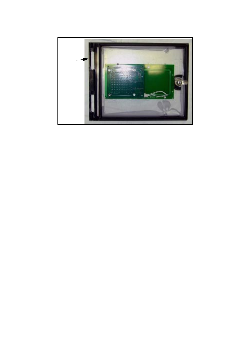
Installing Right Options Door
Install new TRIND/TIRIS right options door (one per side for two-sided units), using pin(s)
removed and saved in Step 6 on page 11. See “Figure 3: Removing options door” on page 11.
Figure 4:
Align door
side for
mounting
pin
PRELIMINARY
MDE-3591A TRIND™ Retrofit Kits C00011-002-XXXX for The Advantrage Series • 3/00 Page 13
Installation
Installing Bulkhead Grommet
1In electronics cabinet, disconnect two cables and remove ground connector to ‘A’ side printer.
Remove printer from unit and save for reinstallation.
2While facing ‘A’ side of unit, measure 6" in toward center of cabinet top from outside edge of
top, and draw a line on top cover. See Figure 5.
3Measure 10.5" in from left side of top, and draw a line. See Figure 4. Intersection of both lines
is pilot hole location.
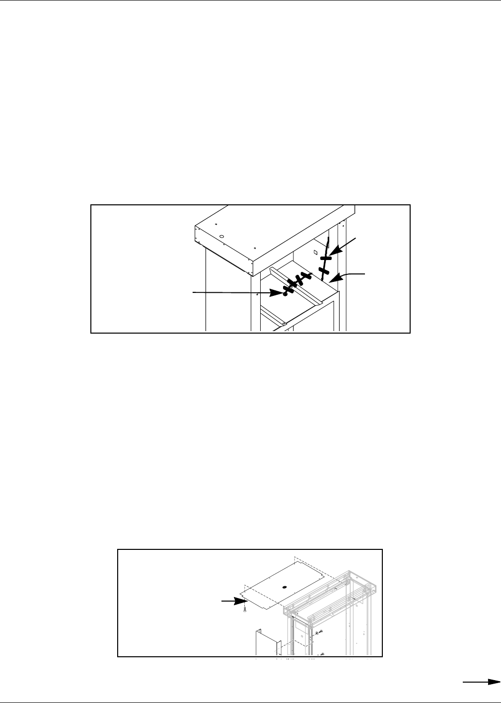
4In packaging materials, locate thick rubber packing that can be broken into flat sided pieces,
approximately six inches round, square or random.
5On one flat side of thick rubber piece, apply light coating of cutting oil.
6With oil coated surfaces in contact with metal surfaces, heavily tape one each foam piece to top
and bottom of main cabinet top, above and below drilling point marked. See Figure 6.
Note: For foam piece taped to top, mark foam with marking pen or pencil to identify drilling
point under foam.Drilling point location accuracy of plus or minus 1/2" is acceptable.
7Cover shelf area under drilling position with plastic. Kit packaging materials may be used.
6"
10.5"
'B' Side
'A' Side
Figure 5:
Locating
bulkhead
grommet
hole
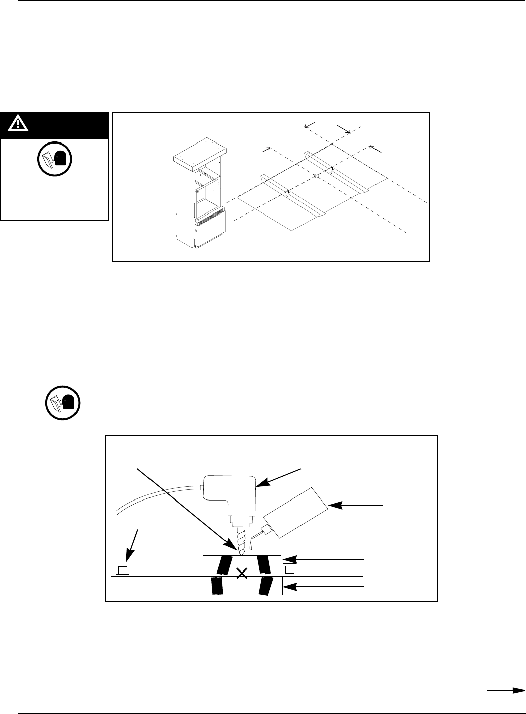
WARNING
The hazard or unsafe
practice could result in
severe injury or death
Cutting oil
Foam pieces
taped to cabinet
above
and below drilling
point
Pneumatic (air) drill
Figure 6: Drilling procedures
Gusset
on
cabinet
top, seen
from side
Drilling point marked
Continued

PRELIMINARY
Installation
Page 14 MDE-3591A TRIND™ Retrofit Kits C00011-002-XXXX for The Advantrage Series • 3/00
8Follow these mandatory safety guidelines:
• Do not use electric drill. Use only pneumatic (air) drill set or controlled for low speed only
(300-500 rpm) or hand operated drill.
• Deposit a few drops of cutting oil at drilling point and on drill bit, to keep bit from
binding, to quench sparks and to bind drill shavings.
9Drill through foam pieces, going only as deep as required to penetrate top cover, beginning
with small diameter bit (approximately 1/8") and gradually increasing bit size until adequate
pilot hole is made.
Note: Hole 3/8" in diameter should be sufficient as pilot for knockout.
10 Remove both top and bottom foam pieces, being careful that all drilling residue and oil is
removed from cabinet area. Wipe off cabinet surface, top and bottom, with clean cloth or rag.
Note: Use file or deburring tool to remove burrs or edges that may cut hands.
11 Using hydraulic or manual knockout punch, make one inch (1") diameter hole.
12 Remove plastic covering hardware by folding inwards to retain any drilling residue, and
dispose of plastic.
13 Carefully check interior of main cabinet for trash or residue and clean as needed.
14 Position bulkhead seal grommet (Q13570-01) with O-ring beneath hole.
15 Secure grommet in place with locking nut from top of cabinet.
16 From ‘A’ side of unit, drop (lower) CRIND tray. Refer to MDE-2531.
CAUTION
Edges of drilled holes
may have sharp edges
or burrs.
Cleaning or working
around drilled
areas not properly
deburred could result in
minor injury.
Do not use electric drill
PRELIMINARY
MDE-3591A TRIND™ Retrofit Kits C00011-002-XXXX for The Advantrage Series • 3/00 Page 15
Installation
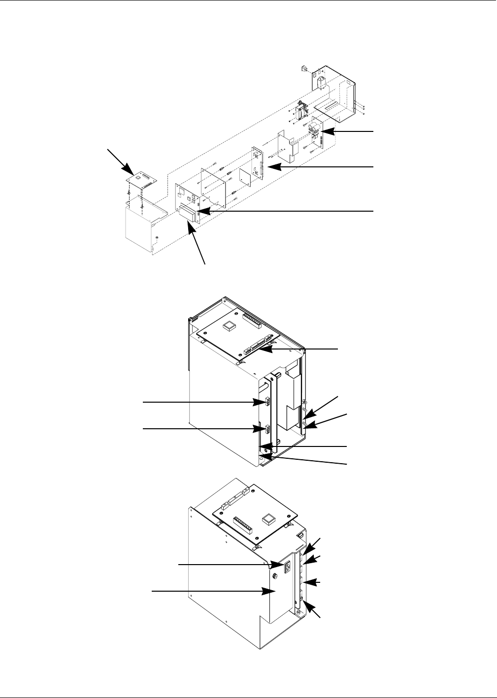
Installing Card Cage Assembly
Install card cage assembly from ‘B’ side of unit according to the following steps:
1Carefully pry out printer cable retainer from underside of printer shelf.
2Pull printer cable out of 2 3/4" round hole from bottom, and install piece of strip grommet
Q10277-02 around perimeter of hole.
3For all single-sided units, connect dummy load connector R20526-01 to JB on transmitter
PCB. See “Card Cage Assembly T20606-G1” on page 25 for connection point.
4Install card cage assembly fuse side first on printer shelf and against center divider behind right
options door, as shown in Figure 7.
5Position card cage so that tab on upper left side of housing fits over latch cutout for main door
latch, securing card cage to divider. See Figure 7.
6From ‘B’ side of unit, feed screw Q12083-13 and washer N16599-48 up through hole in shelf
into threaded hole in card cage bottom.
7Feed three prong female end of power supply cable R20580-G1 up through grommeted hole in
printer shelf to recessed receptacle on card cage assembly. Refer to “Card Cage Assembly
T20606-G1” on page 25 for connection points.
8Secure power cable R20580-G1 in cable retainer removed in Step 1, so that power cable and
printer cable are both secured, and reinstall cable retainer in grommeted hole.
9Feeding cables up through grommeted hole connect P8 (two position, mate and lock) on ‘B’
side data cable M00857A001 to J8 on data control PCB Q13563 in card cage assembly (two
sided units), and connect P7 on ‘A’ side data cable M00857A002 to J7 on data control PCB
Q13563-G4 in card cage assembly (all units).
Note: Caution: do not overtighten cables connectors.
10 Return printer to shelf and reconnect two printer cables and ground connector.
11 Reorient printer and secure to shelf.
Note: Caution: antennas must be connected to card cage transmitter board whenever power
is applied or damage to transmitter board may result.
Figure 7: Card cage locations shown from ‘B’ side
Card cage assembly location behind
right options door
Tab
Card cage assembly
front side
Tab fits over
cutout behind
door latch: see
step 4
PRELIMINARY
Installation
Page 16 MDE-3591A TRIND™ Retrofit Kits C00011-002-XXXX for The Advantrage Series • 3/00
Installing Transmitter Cables
Note: Sharp bends in antenna cables will cause damage. All cable turns must be in loops and
gradual. Refer to “ASC TRIND™ Technology Update” on page 9.
1Feed P1A and B and P3A and B ends of M00878A001 cable assembly (harness) up through
bulkhead grommet in main cabinet.
2Be sure that there is sufficient length (24") of cable assembly remaining in electronics cabinet
to reach connection points on card cage. Cable ends must be routed through underside of card
cage to connection points on ‘B’ side. See “Card Cage Assembly T20606-G1” on page 25 for
connection points.
3Lay M00878 cables flat across top of main cabinet, through gusset opening to column as
shown in Figure 8.
4Use electrical tape to secure cables flat to top of cabinet and in gusset opening. See Figure 8.
5Route M00878 cables from top of main cabinet up along inside of column, keeping cables flat
and parallel. See Figures 7 on page 16and Figure 9 on page 17.
6Loop cables 3" down into space between column and main cabinet and back up again to allow
for reinstallation of inside sheathing. See Figures 8 on page 16and Figure 10 on page 17.
Note: Turn in cables must be gradual, not sharp, to prevent damage to cables.
7Feed cable connector P1A and B and P3A and B ends up through grommet in unit top cover
and leave cable ends there.
8Without removing top sheathing, install piece of strip grommet Q10315-06 along edge of top
sheathing where cables pass in column. See exploded view in Figure 9.
Note: Carefully check for any points where cables are run where cables may come in contact
with sheet metal edges, and install edge grommet to prevent cable damage.
Cables fed through gusset
opening to column and up
inside of column.
Figure 8:
Routing cables to
main cabinet Cables
secured with
electrical
tape
Loop
down and
up to
prevent
tight
bend.
Continued
Edge grommet Q10315-06 to
protect cables from metal
edge of top sheathing
Figure 9:
Installing edge grommet
Exploded View: Do Not
Remove Top Sheathing
From Unit

PRELIMINARY
MDE-3591A TRIND™ Retrofit Kits C00011-002-XXXX for The Advantrage Series • 3/00 Page 17
Installation
9 Lay cables flat and parallel to column and secure with electric tape as shown in Figure 10.
10 Install edge grommet Q10315-06 on bottom edge of inner sheathing (see Figure 10), and
replace inner sheathing, using screws saved during disassembly.
RIGHT
WRONG
Cables
laid flat and
taped to column
Cables
twisted on
top of each
other
Sufficient cable
to make loop, not
sharp turn, back
up to top of main
cabinet. Sharp
bend will damage
cables
Electrical tape
Strip grommet
Q10315-06
on bottom
edge of inner
sheathing
Figure 10:
Cables on column
shown without
main cabinet

PRELIMINARY
Installation
Page 18 MDE-3591A TRIND™ Retrofit Kits C00011-002-XXXX for The Advantrage Series • 3/00
Installing Overhead Antenna and Brackets
Locate mounting brackets in T20625-01 assemblies and do the following:
1Position one each mounting bracket at each short side of unit, for either single or double sided
units.
2Align mounting holes in brackets with holes for hoisting brackets.
3Loosely secure brackets using one bolt (for each bracket) removed and saved in Step 1 of
“Preparing For Installation” on page 10. Utilize bracket hole furthest from antenna assembly,
to allow for lifting of end of bracket and wire access. Do not tighten bolt at this time.
4Using hardware supplied with antenna assembly fasten antenna assembly T20632-G1 (one per
side for two sided units) to antenna bracket(s) T20625-01.
5Lifting side of antenna and bracket assembly, connect P1 and P3 cable connectors for each side
according to table on page 23.
6With connections made, feed connectors back down into upper housing through grommet.
Note: Sufficient lead is provided on antenna wire assemblies to accomplish this.
7Assure that wire leads remaining on top cover fit under raised portion of antenna brackets
when brackets are lowered, and securely fasten antenna bracket(s) to unit top using all
hardware removed and saved in Step 1 of “Preparing For Installation” on page 10.
T20625-01
antenna
brackets
Mounting holes
Antenna assembly
T20632-G1
Raised section
of bracket for
wire trough
Figure 11
PRELIMINARY
MDE-3591A TRIND™ Retrofit Kits C00011-002-XXXX for The Advantrage Series • 3/00 Page 19
Installation
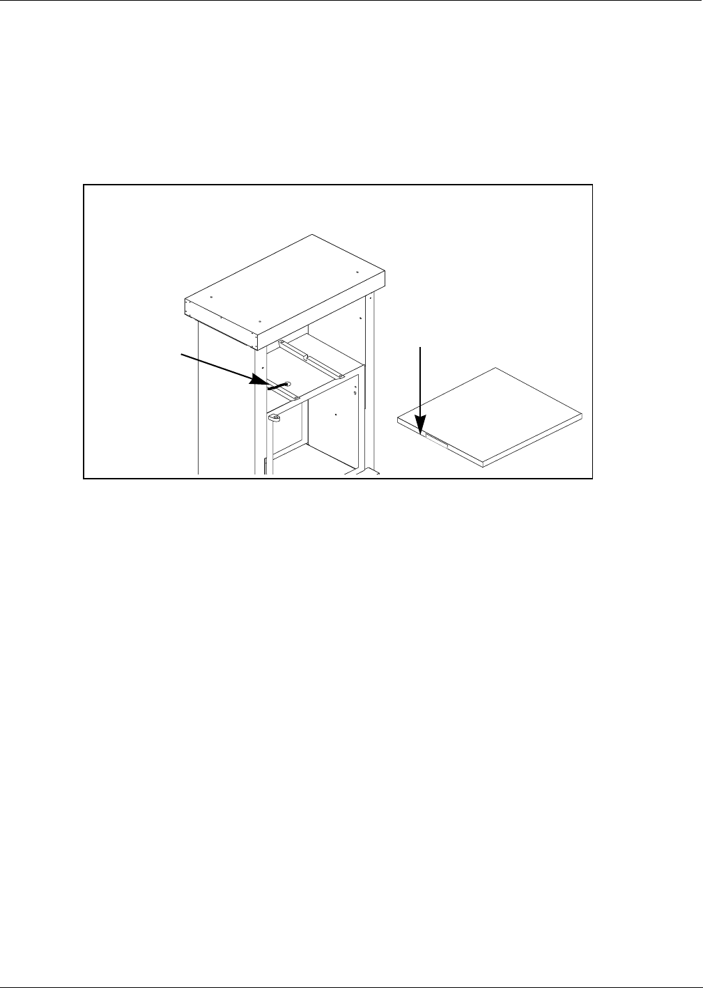
Modifying Cabinet Top Cover
1Use hacksaw to cut 3/8" slots in cabinet top cover to allow strip a minimum of 6" wide to
be folded back with pliers and hammered flat as shown in Figure 10, to allow cables to
pass under top cover to grommet.
Note: Remove top cover from work area to cut slot. Do not cut metal in proximity to
dispensers. Place top cover on cardboard while hammering to prevent damage to
paint.
2Clean edges and burrs around cuts in cover with file or deburring tool.
3Thoroughly seal spaces around and between cables in main cabinet bulkhead grommet
with RTV sealant supplied with kit.
Note: Place some packaging plastic inside bulkhead grommet from top to prevent sealant
from running out bottom when applied.
4For units with upper housing end plates, replace end plate using nine screws removed and
saved with plate.
6” strip
hammered flat
under top cover
Two R20509-G2
and two
Q13578-01 cables
Figure 12:
Slotting top cover

PRELIMINARY
Installation
Page 20 MDE-3591A TRIND™ Retrofit Kits C00011-002-XXXX for The Advantrage Series • 3/00
Routing Cables
Retrofit kit comes with twenty (20) cable clamps, four large (Q13558-06) and sixteen small
(Q13558-08). Number required for proper installation varies with units. Large clamps are for
use with power cable R20580-G1.
Note these variations for routing cable to card cage:
Horse Shoe style CRIND™
For these units, utilize opening in printer shelf bottom for routing.
Pull Out CRIND Tray
For these units utilize round 2-3/4" hole in printer shelf bottom, used for printer cable. Use
cable clamps to secure cables to underside of printer shelf.
Figure 13:
Horse Shoe style
CRIND
Printer shelf
Horse shoe
style module
Opening for cable
routing
Printer shelf with
2-3/4" round hole
Pull out CRIND
electronics tray
Figure 14:
Pull Out
CRIND Tray
Continued

PRELIMINARY
MDE-3591A TRIND™ Retrofit Kits C00011-002-XXXX for The Advantrage Series • 3/00 Page 21
Installation
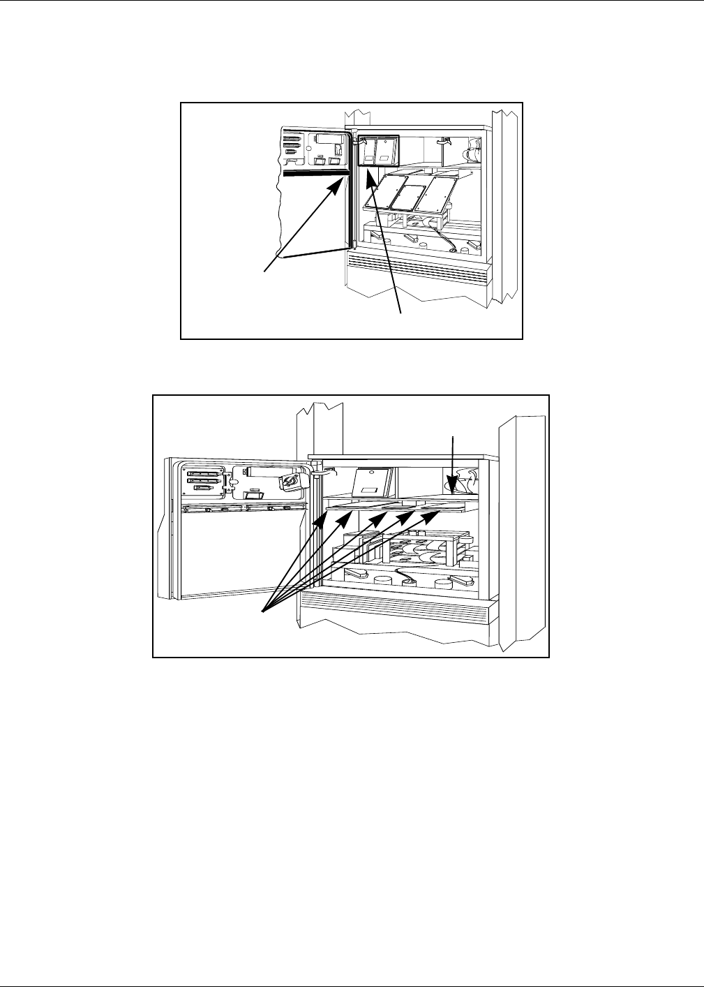
Cable Routing to Option Doors
When routing door cables to card cage, leave excess cable on door, routing cable around edges
of printed circuit board.
Note: It is critical that door cables do not get crimped or pulled when either options door or
main door are opened or closed. Be sure that door cables are secured such that they
cannot be caught in main door. when door is closed, and always close main door before
options door.
• Remove option door shield
• Assuring sufficient cable to reach connection points on card cage, use clamps to secure
cables to underside of lighting frame. Be sure clamps are secured to non-removable part of
frame, so access is maintained for lighting service.
• Route door cables around door electronics and connect cables. See “Connecting Cables”
on page 23.
• Loosely secure cables using tie wrap Q10178-01 and hole on light-microreader printed
circuit board.
• Being sure that option door opens and closes freely without stressing or crimping cables,
use tie wrap Q10178-01 to loosely secure cables to small fixed tab at end of light frame,
forcing cables between light frame and door gasket.
Hole on
PCB for tie
wrap
Feed cables along outside of
hardware, under shield
Figure 15:
Cable routing
on option door
Attach clamps and
cables to underside
of panel light frame
Loosely secure
cables to tab on
light frame with
tie wrap
Figure 16:
Cable routing on
option door continued
Continued
PRELIMINARY
Installation
Page 22 MDE-3591A TRIND™ Retrofit Kits C00011-002-XXXX for The Advantrage Series • 3/00
Cable Routing to Main Cabinet
When routing cables from main door to cabinet, be sure to allow sufficient slack in cables to
allow main door to open and close freely, without pulling on or crimping cables.
Feed cables through 2-3/4" round hole after installing Q10277-02 strip grommet on perimeter.
Stress or
crimping point for
cables
Use clamps to secure cables to underside of shelf
‘A’ Side
Figure 17:
Cable routing
from cabinet to
door
‘B’ Side
Use clamps to
secure cables to
underside of shelf
2-3/4" round hole for
printer cable
Figure 18:
Cable routing under
printer shelf

PRELIMINARY
MDE-3591A TRIND™ Retrofit Kits C00011-002-XXXX for The Advantrage Series • 3/00 Page 23
Installation
Connecting Cables Cable connections for The Advantage Series.
For exploded view of card cage assembly and location of connection points, see “Card Cage
Assembly T20606-G1” on page 25.
For all single-sided units, install dummy load connector R20526-01 on JB on transmitter PCB
and skip all ‘B’ side connections.
Note: If power is applied to card cage without antenna cables or dummy load connected the
transmitter board will be damaged.
Note: * indicates connection point is on card cage assembly.
Note: Route cables R20521-G1 and -G2 and R20437-G01 through bottom of card cage to ‘B’
side for connections.
On Cable Connect To On
M00878A002 PA JA Low Frequency Transmitter Board Q13579-01
PB JB
P2A J2A Ultra High Frequency (UHF) Receiver Board Q13564
(Part of Q13564-04)
P2B J2B
P1A J1A Low Frequency Overhead Antenna (A side)
P3A J3A UHF Receive Antenna (A side)
P1B J1B Low Frequency Overhead Antenna (B side)
P3B J3B UHF Receive Antenna (B side)
M00857A001
A side
P7 J7 Data Control Board (DCB) Q13564-04
J177 P177 Power Supply Board T20314-G1
JA PA R20724-G1 Cable (from Gateway PCB)
J182 P182 Light/Microreader Board T20601-G1
M00857A002
B side
P8 J8 Data Control Board (DCB) Q13564-04
J176 P176 Power Supply Board T20314-G1
JA PA R20724-G1 Cable (from Gateway PCB)
J182 P182 Light/Microreader Board T20601-G1
R20437-G01 J250 P250 Gateway Board T20128-G3
J258A P258 CRIND Logic Board T17764-GX (A side electronics)
J258B P258 CRIND Logic Board T17764-GX (B side electronics)
R20580-G1 AC Power P3 Rear of card cage assembly T20606-G1
P708 J708 AC distribution cable T19612-GX (on A side)
PRELIMINARY
Installation
Page 24 MDE-3591A TRIND™ Retrofit Kits C00011-002-XXXX for The Advantrage Series • 3/00
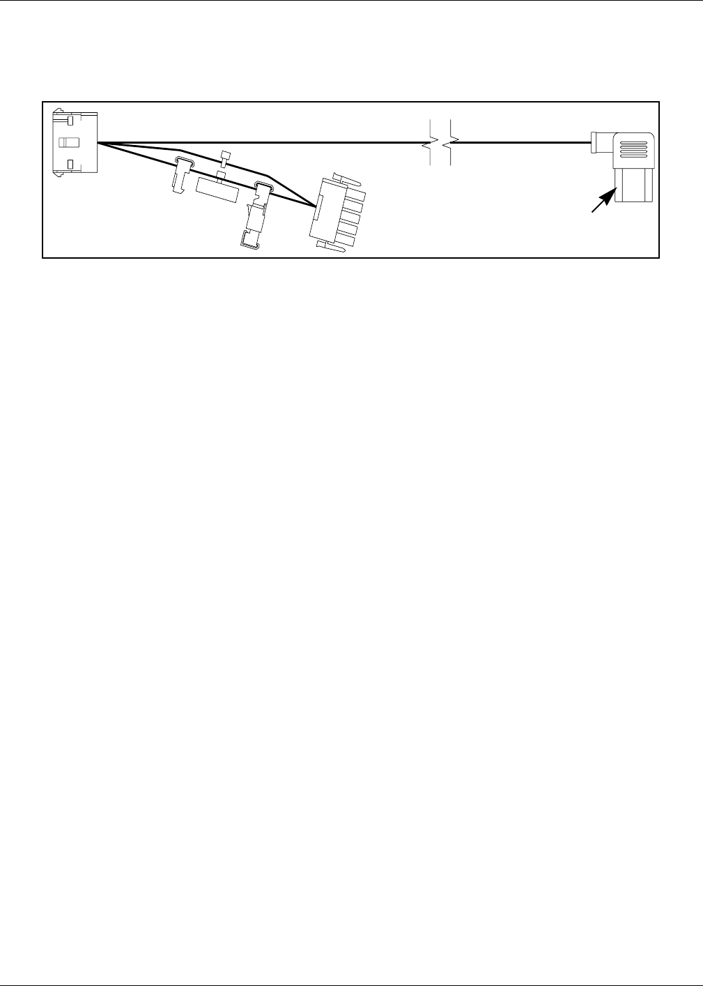
Connections for power supply cable R20580-01 are unit specific. With three prong female end
already in rear of card cage, use appropriate connector to intercept power on existing unit
power cable by installing R20580-01 in-line.
AC PWR
J601/J708
P601/P708
P601
J601
MATE TO
T19612-G2
Figure 19: R20580-G1 Power Cable
To card cage assembly
PRELIMINARY
MDE-3591A TRIND™ Retrofit Kits C00011-002-XXXX for The Advantrage Series • 3/00 Page 25
Card Cage Assembly T20606-G1
Card Cage Assembly T20606-G1
UHF Receiver assembly for Q13578-01 cable connections
Transmitter (low freq) PCB
assembly Q13579-01
Data control board Q13563-04
TIRIS™ gateway PCB
T20128
Power supply PCB
T20314-G1
Figure 20:
Card cage exploded
P250 on TIRIS Gateway PCB T20128-G3
Recessed male three
prong power receptacle
JB on transmitter PCB for ‘B’ side
JA on transmitter PCB for ‘A’ side
P176 on power supply PCB
J2A for ‘A’ side M00878A002 cable
J2B for ‘B’ side M00878A002 cable
P177 on power supply PCB
J8 for ‘B’ side
J7 for ‘A’ side
UL® label
Figure 21:
Cable connection points on
card cage
RS232 port
Ribbon cable

PRELIMINARY
CRIND™ BIOS TRIND™ Upgrade
Page 26 MDE-3591A TRIND™ Retrofit Kits C00011-002-XXXX for The Advantrage Series • 3/00
CRIND™ BIOS TRIND™ Upgrade
Units must have current Z-180 CRIND logic board. Refer to MDE-2628, Cash Acceptor
Retrofit Assemblies for The Advantage® Series Units with CRIND Card Reader in Dispenser.
Install the CRIND Bios TRIND software (K93744-01), one per side, on the T17764-XX
CRIND logic board(s) according to the following steps.
Note: A properly grounded electrostatic discharge wrist strap must be worn during this
procedure.
1Locate and remove existing BIOS at U7 using a grounded chip removal tool.
2Install TRIND BIOS K93744-01 (one per side) at position U7, orienting notch on chip with
indication mark on board as shown in Figure 22.
3For The Advantage® Series units with CRIND tray, restore CRIND tray to operating position.
U7 Chip orientation notch
Figure 22: T17764-XX CRIND logic board BIOS upgrade
JP1-16
Chip
removal
tool
Grounding
strap
Figure 23:
Pulling BIOS chip
PRELIMINARY
MDE-3591A TRIND™ Retrofit Kits C00011-002-XXXX for The Advantrage Series • 3/00 Page 27
Dispenser Set-Up
Dispenser Set-Up
Addressing DispenserEach dispenser on the G-Site controller must be addressed differently; no two dispensers may
have the same address. Address is at discretion of the installer. Follow these steps:
1From A side of unit, locate dip switches on power supply board (PCB) T20314-G1 in card
cage.
2Using switches 2, 3, 4 and 5 address each dispenser according to the following table:
Note: Switch one in down position is standalone mode selected, used for service only.
Switch Numbers = Value
1 = Standalone Mode
2 = 1
3 = 2
4 = 4
5 = 8 1
2
3
4
5
Dip switch down Dip switch up
Figure 24

PRELIMINARY
Dispenser Set-Up
Page 28 MDE-3591A TRIND™ Retrofit Kits C00011-002-XXXX for The Advantrage Series • 3/00
Addressing Gateway Board
Address for TRIND™ must match address on CRIND™ logic board. Follow these steps for
each side of unit:
1Locate CRIND logic board T17764-XX.
2Note position of jump jacks and set jump jacks on Gateway board T20128 to match address on
CRIND logic board.
Note: For double-sided units set address for both A and B sides.
MOC and Generic CRIND Addresses.
Address On CRIND Logic Board T17764-XX JP8 JP7 JP6 JP5 JP4
= Address on Gateway Board T20128 ‘A’ Side JP6 JP7 JP8 JP9 JP10
= Address on Gateway Board T20128 ‘B’ Side JP14 JP15 JP16 JP17 JP18
1 IN OUT OUT OUT OUT
2 OUT IN OUT OUT OUT
3 IN IN OUT OUT OUT
4 OUT OUT IN OUT OUT
5 IN OUT IN OUT OUT
6 OUT IN IN OUT OUT
7 INININOUTOUT
8 OUT OUT OUT IN OUT
9 INOUTOUTINOUT
10 OUT IN OUT IN OUT
11 IN IN OUT IN OUT
12 OUT OUT IN IN OUT
13 IN OUT IN IN OUT
14 OUTINININOUT
15 IN IN IN IN OUT
16 OUT OUT OUT OUT IN
17 IN OUT OUT OUT IN
18 OUT IN OUT OUT IN
19 IN IN OUT OUT IN
20 OUT OUT IN OUT IN
21 IN OUT IN OUT IN
22 OUT IN IN OUT IN
23 IN IN IN OUT IN
24 OUT OUT OUT IN IN
25 IN OUT OUT IN IN
26 OUT IN OUT IN IN
27 IN IN OUT IN IN
28 OUT OUT IN IN IN
29 IN OUT IN IN IN
30 OUTININININ
31 IN IN IN IN IN
32 OUT OUT OUT OUT OUT

PRELIMINARY
MDE-3591A TRIND™ Retrofit Kits C00011-002-XXXX for The Advantrage Series • 3/00 Page 29
Dispenser Set-Up
Preparation for Tuning Antennas
Antenna tuning requires use of field strength sensor Q13626-01 supplied with ASC tool kit.
1For units without G-Site™ put unit in ‘Stand Alone’ mode by disconnecting J4 on the DCB
board and placing jumper on light microreader board at JP3.
Note: JP3 and J4 can never both be in or both out. One and only one must always be in, the
other out.
2Restore power to unit(s) and cold start the CRIND. Refer to MDE-2562, CRIND Service
Manual for detailed instructions.
Note: Be sure transmitter cables are connected before restoring power.
3Once the CRIND display indicates unit is downloading, remove the Cold Start jump jack.
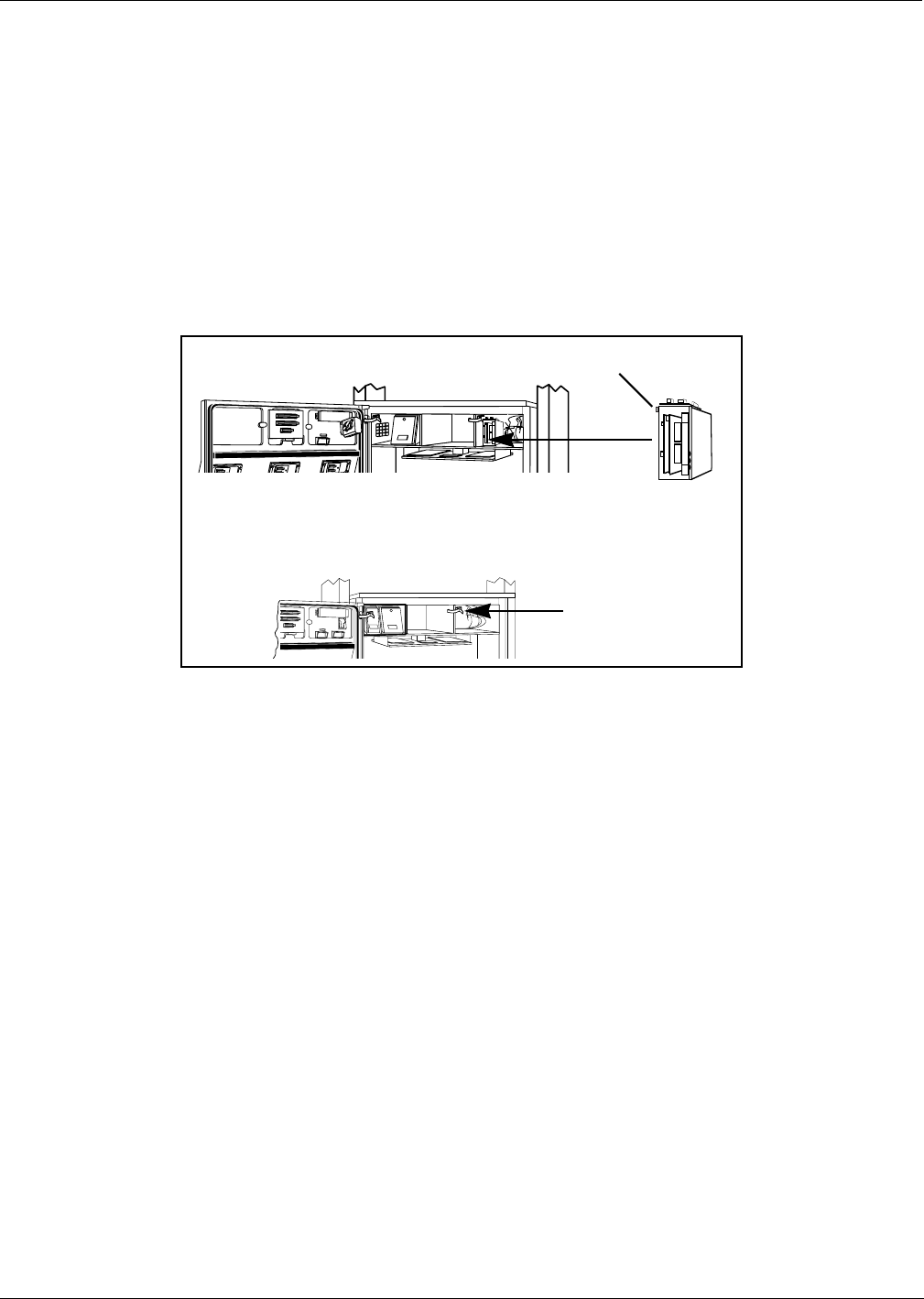
Tuning Antennas Do the following for each side:
1Locate tuning pot access hole on underside of antenna enclosure. Pot has slot for tuning tool.
2Tuning pot in over head antenna enclosure should be turned out 5 to 6 turns.
Note: Use tuning tool Q13631-01 from the ASC TRIND tool kit to make pot adjustments.
Refer to MDE-3640 ASC TRIND Tool Kit for instructions.
3Hang field strength sensor in position shown on overhead antenna, to right of antenna
enclosure. See Figure 25.
Antenna assembly
T20632-G1
Figure 25
Tuning pot access
Hang field strength test
meter
Continued

PRELIMINARY
Dispenser Set-Up
Page 30 MDE-3591A TRIND™ Retrofit Kits C00011-002-XXXX for The Advantrage Series • 3/00
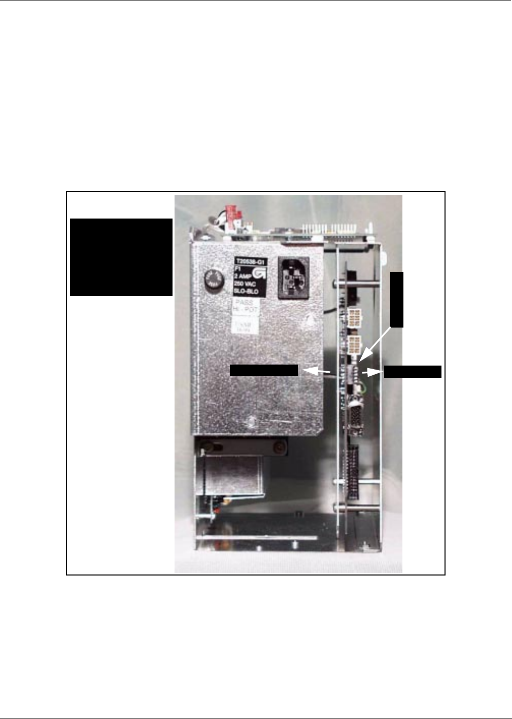
4On card cage, move three position ‘tune’ toggle switch from center position to ‘A’. See Figure
26.
5Connect leads on multi-meter set to DC voltage to field strength sensor.
6By fine adjustments to tuning pot, set to highest DC voltage reading.
Note: Voltage will peak at a point, and then decrease with turns in either direction. Set at
peak.
7After completing steps for all sides return tune toggle switch to center position.
‘Tune’ toggle
switch location
Figure 26:
Tune toggle
switch

PRELIMINARY
MDE-3591A TRIND™ Retrofit Kits C00011-002-XXXX for The Advantrage Series • 3/00 Page 31
Dispenser Set-Up
Testing TRIND™ 1From ‘A’ side of unit touch hand held test tag (Q13630-02 from the ACS TRIND tool kit) to
TRIND target graphic. Door or faceplate TRIND indicator will light.
Note: If indicator fails to light check whether light on other side is on; if so it indicates a
crossing of ‘A’ and ‘B’ side cables. Check connections.
2From ‘A’ side of unit hold car mount test tag (Q13630-01 from the ASC TRIND tool kit) in
front of unit, at a distance of approximately 6 feet from overhead antenna. Door or faceplate
TRIND indicator will light.
3Repeat Steps 1 through 3 for ‘B’ side.
Alternative Testing Using Laptop
1Connect laptop to RS232 port on DCB.
2Go to:
• Windows program
• Accessories
•Terminal
• Settings
• Communications
3Set for:
• 9600 baud
•8 bit
• No parity
• Comm 1
4Then go to:
• Help screen
• Antenna scan
• Choose 1, 2, 3 and 4
Note: This will test both antennas
5From ‘A’ side of unit touch hand held test tag (Q13630-02 from the ACS TRIND tool kit) to
front of TRIND target graphic. Door or faceplate TRIND indicator will light.
6From ‘A’ side of unit hold car mount test tag (Q13630-01 from the ASC TRIND tool kit) in
front of unit, at a distance of approximately 6 feet from overhead antenna. Door or faceplate
TRIND indicator will light.
7Repeat Steps 5 and 6 for ‘B’ side.
Setting Baud Rate For major oil company (MOC) TRIND™ installations there is no requirement to set or change
baud rate.
PRELIMINARY
Dispenser Set-Up
© 2000 Marconi Commerce Systems Inc.
7300 West Friendly Avenue • Post Office Box 22087
Greensboro, North Carolina 27420
Phone (336) 547-5000 • http://www.marconicommerce.com • Printed in the U.S.A.
MDE-3591A TRIND™ Retrofit Kits C00011-002-XXXX for The Advantrage Series • 3/00
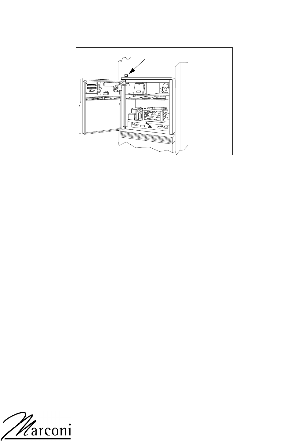
Installing FCC Label Plate
For all units install FCC label plate N23949-01 according to the following:
Note: Label on plate is identified as N23949-01 on lower left corner of label.
1Peel paper backing off FCC nameplate N23949-01 to expose adhesive on back of plate.
2From A side of unit, affix FCC label plate to left side inner sheathing, above main cabinet top
cover.
3Press nameplate firmly in place to secure adhesive bond.
Location for FCC label plate N23949-01