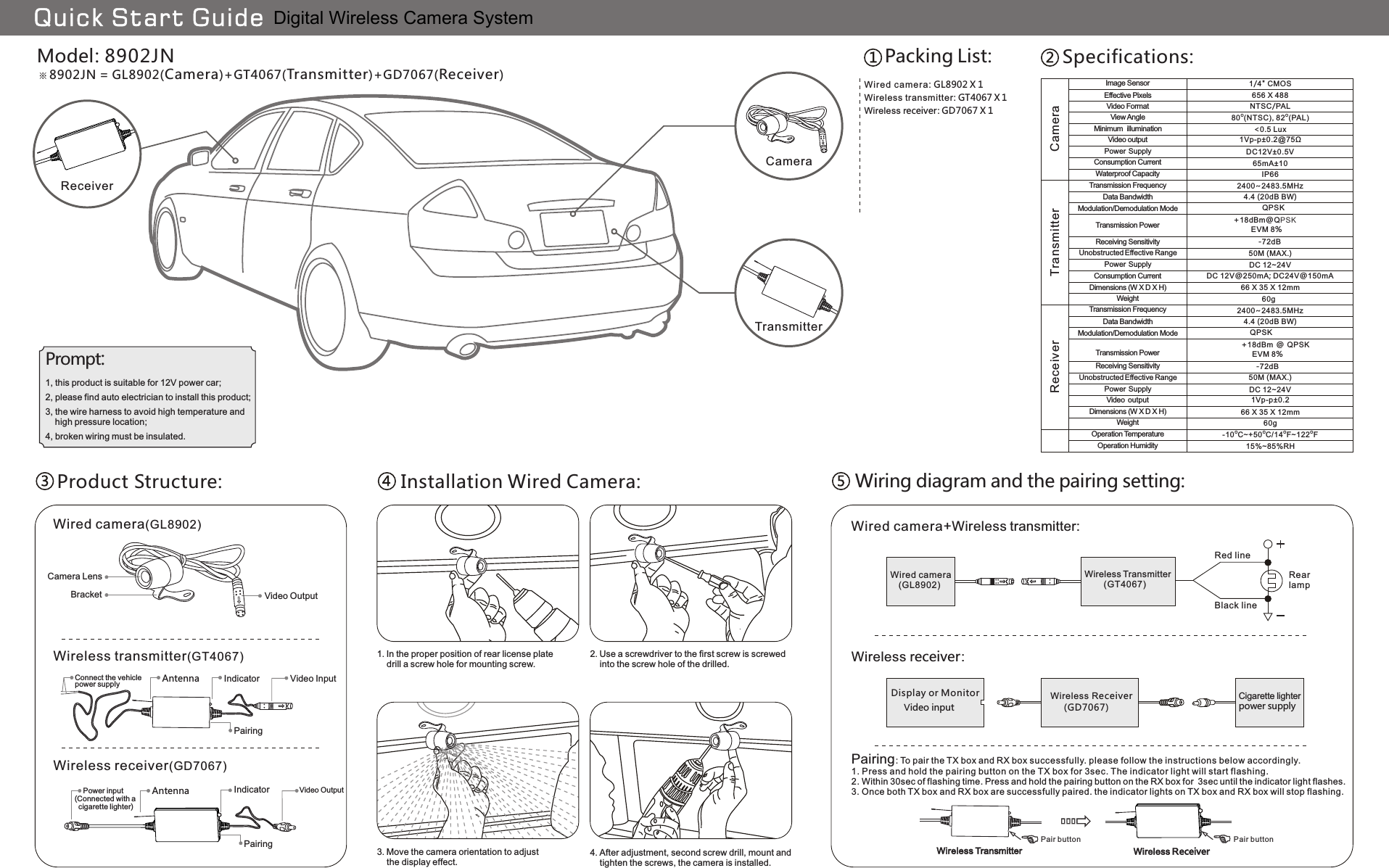
Gospell Smarthome Electronic GD7067 Digital Wireless Camera System User Manual GT4067 GD7067 QSG

Shenzhen Gospell Smarthome Electronic Co., Ltd. Digital Wireless Camera System GT4067 GD7067 QSG

User Manual

60g66 X 35 X 12mmDC 12~24V50M (MAX.)2400~2483.5MHz4.4 (20dB BW) QPSK+18dBm @ QPSK       EVM 8%-72dBO O O O-10 C~+50 C/14 F~122 F15%~85%RH60g66 X 35 X 12mmDC 12V@250mA; DC24V@150mADC 12~24V50M (MAX.)2400~2483.5MHz4.4 (20dB BW)              QPSK      +18dBm@QPSK                 EVM 8%                  -72dB IP6665mA±101Vp-p±0.2@75Ω<0.5 LuxO O80 (NTSC), 82 (PAL)DC12V±0.5V1Vp-p±0.21/4" CMOS656 X 488NTSC/PALModel: 8902JN8902JN = GL8902(Camera)+GT4067(Transmitter)+GD7067(Receiver)WGL8902ired camera:   X 1Wireless receiver )(GD7067Wireless transmitter )(GT4067Wired camera(GL8902)Wireless Transmitter       (GT4067)Wired camera   (GL8902)Wireless Receiver      )(GD7067Display or MonitorBlack lineRed line    Power input(Connected with a   cigarette lighter)IndicatorAntennaConnect the vehicle power supplyBracketCamera LensPrompt:TransmitterReceiverQuick Start GuideCameraCameraTransmitterReceiverUnobstructed Effective RangeUnobstructed Effective RangePower  SupplyWeightReceiving SensitivityWeightDimensions (W X D X H)Receiving SensitivityPower  SupplyVideo  outputDimensions (W X D X H)Operation HumidityOperation TemperatureTransmission PowerTransmission PowerModulation/Demodulation ModeModulation/Demodulation ModeImage SensorEffective PixelsVideo FormatMinimum  illuminationView AngleConsumption CurrentVideo outputPower  SupplyWaterproof CapacityConsumption CurrentTransmission FrequencyTransmission FrequencyData BandwidthData BandwidthPacking List: Specifications:Product Structure: Installation Wired Camera:Video OutputVideo InputPairingVideo OutputIndicatorAntennaPairing1. In the proper position of rear license plate    drill a screw hole for mounting screw.2. Use a screwdriver to the first screw is screwed    into the screw hole of the drilled.3. Move the camera orientation to adjust    the display effect.4. After adjustment, second screw drill, mount and     tighten the screws, the camera is installed.Wiring diagram and the pairing setting:Wired camera+Wireless transmitter:RearlampWireless receiver:Cigarette lighterpower supplyVideo inputWireless ReceiverWireless Transmitter1, this product is suitable for 12V power car;2, please find auto electrician to install this product;4, broken wiring must be insulated.3, the wire harness to avoid high temperature and     high pressure location;Wireless receiver: GD7067 X 1Pairing: To pair the TX box and RX box successfully. please follow the instructions below accordingly.1. Press and hold the pairing button on the TX box for 3sec. The indicator light will start flashing.2. Within 30sec of flashing time. Press and hold the pairing button on the RX box for  3sec until the indicator light flashes.3. Once both TX box and RX box are successfully paired. the indicator lights on TX box and RX box will stop flashing.Pair button Pair buttonWireless transmitter:   X 1GT4067Digital Wireless Camera System
 FCC Warning Statements: Changes or modifications not expressly approved by the party responsible for compliance could void the user’s authority to operate the equipment.    This equipment has been tested and found to comply with the limits for a Class B digital   device, pursuant to part 15 of the FCC Rules. These limits are designed to provide reasonable protection against harmful interference in a residential installation. This equipment generates, uses and can radiate radio frequency energy and, if not installed and used in accordance with the instructions, may cause harmful interference to radio communications. However, there is no guarantee that interference will not occur in a particular installation. If this equipment does cause harmful interference to radio or television reception, which can be determined by turning the equipment off and on, the user is encouraged to try to correct the interference by one or more of the following measures:   - Reorient or relocate the receiving antenna.   - Increase the separation between the equipment and receiver.   -Connect the equipment into an outlet on a circuit different from that to which the receiver is   connected.   -Consult the dealer or an experienced radio/TV technician for help.   “RF Exposure Guidance: This equipment complies with FCC radiation exposure limits set forth for an uncontrolled environment. This equipment should be operated with a minimum distance of 20cm between the radiator and persons. This transmitter must not be co-located or operating in conjunction with any other antenna or transmitter, except in accordance with FCC multi-transmitter product procedures.”

Navigation menu