Gospell Smarthome Electronic GT4065 2.4G Wireless Rearview Camera and Receiver User Manual 8907AZ OEM XIAO
Shenzhen Gospell Smarthome Electronic Co., Ltd. 2.4G Wireless Rearview Camera and Receiver 8907AZ OEM XIAO
User manual
2.4GHz Wireless
Camera
Model: 890
Car Rearview
and Receiver
2BG 8902MJ

CONTENTS
1. Foreword
2. Packing List
3. Structure
4. Installation
6. FCC Information
5. Specifications
1
1
2
3
11
Back Cover
* 89 means 890 + G 406 +02BG 2 T 5 T 013
8902MJ means GL8902 GT4065 Gb6904
GL G 4
*++
-1-
1. FOREWORD
CONGRATULATIONS. The Wireless Camera, when used as
described, w
car rearview
ill give you years of dependable service in your car, truck,
RV, or mini-van. We have taken numerous measures in quality control to
ensure that your product arrives in top condition, and will perform to your
satisfaction.
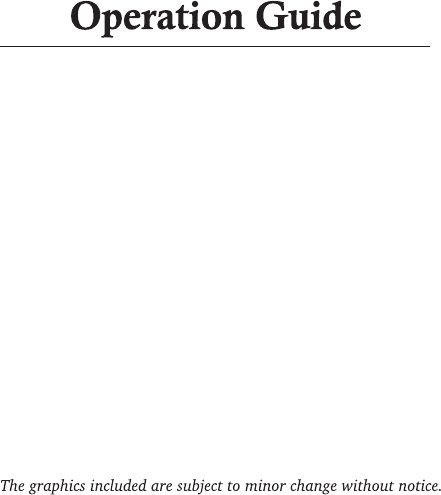
2. PACKING LIST
Car Rearview Camera
Receiver G 40132.4GHz Wireless T
Wireless Transmission Box Gt4065
2.4GHz wireless Receiver GB6904
conversion cord
-2-
-3-
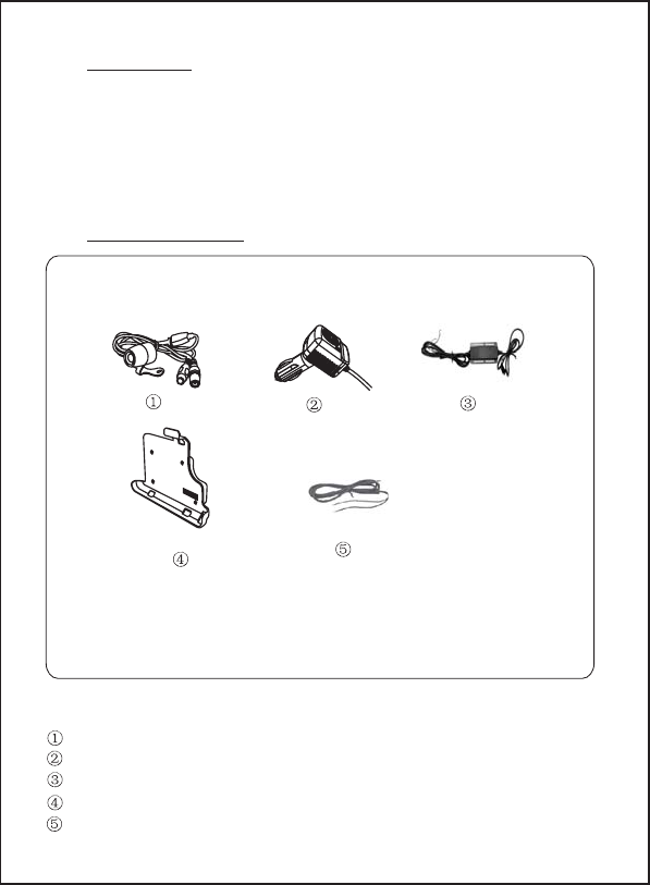
3. STRUCTURE
Connector Wire
to Gt4065
Gl8902
3-1 CameraCar Rearview
Wireless Transmission Box
Power Wire
Gt4065
Connector to
Gl8902
-4-
4. INSTALLATION
These installation instructions do not apply to all vehicles. They are
meant as only as a general guide due to common vehicle makes &
models. For specific questions, contact your vehicle's manufacturer.
Consult your local motor vehicle laws on the use of this product.
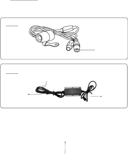
4-1 CAMERA INSTALLATION
You may mount the camera near the license plate's top with screws.
1. Uplift the backside door of
vehicle and the cover to
install profitably. (Fig1)
remove
2. Drill three holes. The one hole for
the c ire and two holes for
camera. (Fig2)
onnector w
installation of the (Fig1)
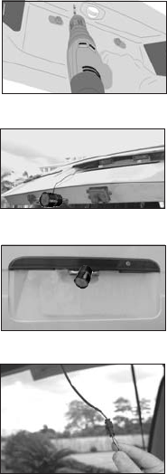
-5-
(Fig2)
Note:
* Some vehicle's may have a hole
available to pass the wire through, if not,
you need to drill a hole close to the location
of camera for the connector wire, and two
holes for the screws of camera installation.
* Before you drill those holes, you must
check out and make sure no other
components too close to your aiguille.
Before drilling, we strongly commend you
remove electrical parts or fuel system
behind the vehicle door and clear the
surroundings to avoid unexpected damages.
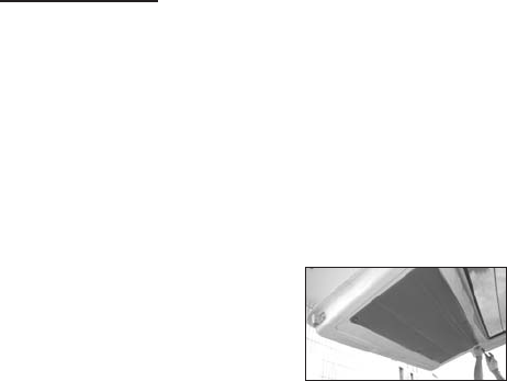
3. If the holes are all ready, pass the
of camera into the vehicle.(Fig3)
Install the camera by two screws supplied
and adjust the camera to an proper angle.
(Fig 4)
connector
wire
(Fig3)
(Fig 4)
(Fig 5)
4. Then connect the camera to the
transmission box GT406 .(Fig5)5
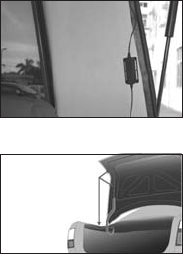
5. Fix the transmission box Gt406
on the surface by the sheet screws we
supplied. (Fig6)
5
Note:
* Generally we advise you put it on the
center of the license plate top.
6. Next you'll need to find the vehicle's reverse lights. Turn off the
vehicle's reverse lights. Turn the vehicle's ignition key to the accessory
position, engage the parking brake and put the car in reverse. Look at
the vehicle's tail lights to see where the reverse lights are located, they
are the white lights.
(Fig7)
To locate the reverse light's 12/24VDC wire
it will be necessary to gain access to the rear
of the vehicle's tail light.
For help locating the vehicle's reverse light
circuit contact your vehicle's manufacturer
for vehicle specific wiring diagrams.
7.Once you have located the reverse light
circuit you will have to route the GT4062
Power Wire to that location. You must
securely fasten the Power Wire to prevent
it from being caught on any vehicle
component such as the trunk
hinge (Fig. 7). Never route the cable
outside the vehicle.
8.The reverse light sockets on most vehicles have two wires connected
to them. Usually the negative wire is black and the positive wire is a
colored wire. If you are uncertain about the wiring, you can use a 12/24
volt test light available at most auto parts stores to determine which is
the positive wire.
Camera's
Power Cable
Camera's
Power Cable
a.Remove the reverse light socket from its housing, then remove the blub
from the socket.
b.Engage the parking brake, turn the ignition key to the ON position, but
do not start the vehicle. Put the gear shift in the reverse position.
c.Attach the ground wire of the test light to the vehicle ground, then
touch one of the socket's contacts with the positive lead.
-6-
d. If the test light lights up, then the wire corresponding to that contact
is the positive wire. If it doesn't light up the opposite wire is the
positive wire.
9. After determining which wire is the positive and which is the negative,
turn off the ignition key, then remove the battery's negative cable.
Follow the manufacturer's instructions for the safe use of the test light.
(Fig6)
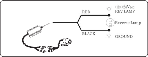
-7-
12. Replace the reverse light bulb, then reinstall the light socket. Secure
all the wire with cable ties or electrical tape. Reattach the negative
battery cable to the battery.
11. Next splice the black wire of the transmission box GT4062 power
wire to the reverse light's negative(-) wire or ground.
Wiring Connector Diagram
G 406 is equipped with Reverse Voltage Protection. If the camera
does not operate, please check that the Red wire is connected to positive
(+) and the Black wire is connected to negative(-).
t5
10. Following the In-Line Wire Connector Instructions section, splice the
Red wire using the supplied In-Line Wire Connector to the reverse light's
positive(+) wire. Use a set of slip joint pliers to squeeze the TAP and
insure good connection.
You do not need to use the In-Line Wire Connectors. can
wired directly to the reverse light circuit by stripping the reverse light
wires then twisting GT4062 wires to the exposed reverse light wires.
Once connected, wrap with electrical tape. Do not attempt this if you
are not knowledgeable with electrical installation practices.
GT4062 be
-8-
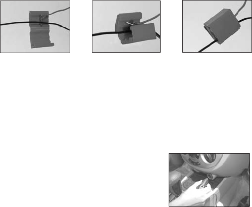
In-Line Wire Connector Instructions
Insert the existing
wire to be tapped. Insert the wire to
be attached.
Crimp tap then
close lock
4-2:12/24 Volt Cigarette Lighter Adapter
Using
age and
2 4GHz wireless Receiver Gt4013.
1. Plug the end of the power cable into the
.electric equipment
3. Plug the 12/24 V car power adapter into
car power socket.
4. The monitor or GPS will be automatically activated when you back up the car.
The monitor will be automatically shut when t goes forward.he car
2.Plug the end of the AV cable into the AV
equipment
4-3 2.4GHz wireless Receiver Gb6904 using
1 Clamp the Gb6904 on a GPS. equipment
2 the GPS equipment will supply 5V voltage to the Receiver and
the Receiver can supply AV signal to GPS
.
.
3 The monitor of GPS. will be automatically activated when you
clamp the Receiver
--9
(Max.)
150mA
-
-
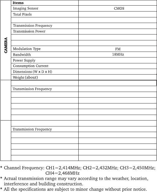
Modulation
Input voltage
Output current
FM
12V 24V DC/
15A.
Output Voltage
5V
Received Sensitivity
≤-85dBm
510 96 628 84 (NTSC) 5 6(PAL)
ISM 2,400-2,483MHz
ISM 2,400-2,483MHz
Minimum Illumination
IR Night Range
Horizontal View Angle
80 degree
GL8902+GT4065
<0. Lux5
4m
+12 DCV
2mW/FCC,10wm/CE
Consumption Current (Max.)
15A.
5. SPECIFICATIONS
RECEIVERGT4013
Modulation
Input voltage
Output current
FM
5V DC
110mA
Video output level
1 1Vpp.
Received Sensitivity
≤- dBm93
ISM 2,400-2,483MHz
Video output impedance
75Ω
RECEIVERGB4096
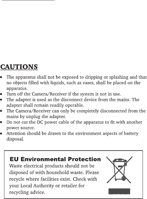
FCC INFORMATION
This device complies with part15 of the FCC Rules. Operation is subject
to the following two conditions:
(1) this device may not cause harmful interference,
(2) this device must accept any interference received, including
interference that may cause undesired operation.
Changes or modifications not expressly approved by the party responsible
for compliance could void the user’s authority to operate the
equipment.
--10
GOSPELL Smarthome Electronic CO.,LTD.
4-5Floor/Block 2, Vision (SZ) Park, Hi-Tech Industrial Park, Shenzhen, P.R.China