Graco 312066Z Reactor Electric Proportioners Users Manual 312066Z, Reactor, Proportioners, Repair Parts, (English)
2015-04-02
: Graco Graco-312066Z-Reactor-Electric-Proportioners-Users-Manual-686245 graco-312066z-reactor-electric-proportioners-users-manual-686245 graco pdf
Open the PDF directly: View PDF ![]() .
.
Page Count: 74
- Models
- Supplied Manuals
- Related Manuals
- Warnings
- Temperature Control Diagnostic Codes
- Motor Control Diagnostic Codes
- Alarms
- Warnings
- E21: No component A transducer
- E22: No component B transducer
- E23: High fluid pressure
- E24: Pressure Imbalance
- E25: High line voltage
- E26: Low line voltage
- E27: High Motor Temperature
- E28: High current in motor
- E29: Brush Wear
- E31: Motor Control Failure (E-30 and E-XP2 only)
- E32: Motor Control Overtemperature
- Communication Diagnostic Codes
- Troubleshooting
- Repair
- Before Beginning Repair
- Pressure Relief Procedure
- Flushing
- Pump Removal
- Pump Installation
- Drive Housing
- Motor Brushes
- Capacitor Test
- Circuit Breaker Module
- Electric Motor
- Motor Control Board
- Transducers
- Electric Fan
- Temperature Control Module
- Primary Heaters
- Heated Hose
- Fluid Temperature Sensor (FTS)
- Display Module
- Inlet Fluid Strainer Screen
- Pump Lubrication System
- Parts
- 248669 Conversion Kit
- Dimensions
- Technical Data
- Graco Standard Warranty
- Graco Information
9902471
Conforms to ANSI/UL
Std. 499 Certified to
CAN/CSA Std.
C22.2 No. 88
Repair - Parts
Electric, Heated, Plural Component Proportioner. For spraying polyurethane foam and
polyurea coatings. For professional use only.
Not approved for use in European explosive atmosphere locations.
See page 3 for model information, including
maximum working pressure and approvals.
Important Safety Instructions
Read all warnings and instructions in this
manual. Save these instructions.
312066Z
EN
Model E-XP1 Shown
TI10953a
2312066Z
Contents
Models . . . . . . . . . . . . . . . . . . . . . . . . . . . . . . . . . . . 3
Supplied Manuals . . . . . . . . . . . . . . . . . . . . . . . . . . 4
Related Manuals . . . . . . . . . . . . . . . . . . . . . . . . . . . 4
Warnings . . . . . . . . . . . . . . . . . . . . . . . . . . . . . . . . . 5
Temperature Control Diagnostic Codes . . . . . . . . 8
E01: High fluid temperature . . . . . . . . . . . . . . . . 8
E02: High zone current . . . . . . . . . . . . . . . . . . . . 9
E03: No zone current . . . . . . . . . . . . . . . . . . . . 10
E04: Fluid Temperature Sensor (FTS) or
thermocouple disconnected . . . . . . . . . . . . 10
E05: Circuit board overheated . . . . . . . . . . . . . 10
E06: Communication cable unplugged . . . . . . . 10
Motor Control Diagnostic Codes . . . . . . . . . . . . . 11
Alarms . . . . . . . . . . . . . . . . . . . . . . . . . . . . . . . . 11
Warnings . . . . . . . . . . . . . . . . . . . . . . . . . . . . . . 11
E21: No component A transducer . . . . . . . . . . . 12
E22: No component B transducer . . . . . . . . . . . 12
E23: High fluid pressure . . . . . . . . . . . . . . . . . . 12
E24: Pressure Imbalance . . . . . . . . . . . . . . . . . 12
E25: High line voltage . . . . . . . . . . . . . . . . . . . . 14
E26: Low line voltage . . . . . . . . . . . . . . . . . . . . 14
E27: High Motor Temperature . . . . . . . . . . . . . 14
E28: High current in motor . . . . . . . . . . . . . . . . 14
E29: Brush Wear . . . . . . . . . . . . . . . . . . . . . . . . 14
E31: Motor Control Failure
(E-30 and E-XP2 only) . . . . . . . . . . . . . . . . 15
E32: Motor Control Overtemperature . . . . . . . . 16
Communication Diagnostic Codes . . . . . . . . . . . 16
E30: Momentary loss of communication . . . . . . 16
E99: Loss of communication . . . . . . . . . . . . . . . 16
Troubleshooting . . . . . . . . . . . . . . . . . . . . . . . . . . 17
Reactor Electronics . . . . . . . . . . . . . . . . . . . . . . 18
Primary Heaters (A and B) . . . . . . . . . . . . . . . . 20
Hose Heat System . . . . . . . . . . . . . . . . . . . . . . 21
Repair . . . . . . . . . . . . . . . . . . . . . . . . . . . . . . . . . . . 23
Before Beginning Repair . . . . . . . . . . . . . . . . . . 23
Pressure Relief Procedure . . . . . . . . . . . . . . . . 23
Flushing . . . . . . . . . . . . . . . . . . . . . . . . . . . . . . . 24
Pump Removal . . . . . . . . . . . . . . . . . . . . . . . . . 24
Pump Installation . . . . . . . . . . . . . . . . . . . . . . . . 26
Drive Housing . . . . . . . . . . . . . . . . . . . . . . . . . . 28
Motor Brushes . . . . . . . . . . . . . . . . . . . . . . . . . . 30
Capacitor Test . . . . . . . . . . . . . . . . . . . . . . . . . . 32
Circuit Breaker Module . . . . . . . . . . . . . . . . . . . 32
Electric Motor . . . . . . . . . . . . . . . . . . . . . . . . . . . 33
Motor Control Board . . . . . . . . . . . . . . . . . . . . . 34
Transducers . . . . . . . . . . . . . . . . . . . . . . . . . . . . 36
Electric Fan . . . . . . . . . . . . . . . . . . . . . . . . . . . . 36
Temperature Control Module . . . . . . . . . . . . . . . 37
Primary Heaters . . . . . . . . . . . . . . . . . . . . . . . . . 40
Heated Hose . . . . . . . . . . . . . . . . . . . . . . . . . . . 43
Fluid Temperature Sensor (FTS) . . . . . . . . . . . . 44
Display Module . . . . . . . . . . . . . . . . . . . . . . . . . 46
Inlet Fluid Strainer Screen . . . . . . . . . . . . . . . . . 48
Pump Lubrication System . . . . . . . . . . . . . . . . . 48
Parts . . . . . . . . . . . . . . . . . . . . . . . . . . . . . . . . . . . . 50
Reactor Assembly (Model E-XP1 Shown) . . . . . 50
Parts Used on All Models . . . . . . . . . . . . . . . . . 53
Parts that Vary by Model . . . . . . . . . . . . . . . . . . 54
Sub Assemblies . . . . . . . . . . . . . . . . . . . . . . . . . 58
Proportioner Module . . . . . . . . . . . . . . . . . . . . . 58
Fluid Heaters . . . . . . . . . . . . . . . . . . . . . . . . . . . 60
7.65 kW Single Zone Fluid Heater . . . . . . . . . . . 61
Reactor Frame . . . . . . . . . . . . . . . . . . . . . . . . . . 62
Display . . . . . . . . . . . . . . . . . . . . . . . . . . . . . . . . 63
Temperature Control . . . . . . . . . . . . . . . . . . . . . 64
Motor Control . . . . . . . . . . . . . . . . . . . . . . . . . . . 65
Fluid Manifold . . . . . . . . . . . . . . . . . . . . . . . . . . 66
Circuit Breaker Modules . . . . . . . . . . . . . . . . . . 67
248669 Conversion Kit . . . . . . . . . . . . . . . . . . . . . 71
Dimensions . . . . . . . . . . . . . . . . . . . . . . . . . . . . . . . 72
Technical Data . . . . . . . . . . . . . . . . . . . . . . . . . . . . 73
Graco Standard Warranty . . . . . . . . . . . . . . . . . . . 74
Graco Information . . . . . . . . . . . . . . . . . . . . . . . . . 74

Models
312066Z 3
Models
E-20 SERIES
E-30 SERIES
E-XP1 SERIES
E-XP2 SERIES
* Full load amps with all devices operating at maximum capabilities. Fuse requirements at various flow rates and mix
chamber sizes may be less.
†
Total system watts, based on maximum hose length for each unit:
• E-20 and E-XP1 series, 210 ft (64 m) maximum heated hose length, including whip hose.
• E-30 and E-XP2 series, 310 ft (94.5 m) maximum heated hose length, including whip hose.
◆
Maximum flow rate given for 60 Hz operation. For 50 Hz operation, maximum flow rate is 5/6 of 60 Hz maximum
flow.
Part, Series
Full Load Peak
Amps*
Voltage
(phase)
System
Watts†
Primary
Heater
Watts
Max Flow
Rate◆
lb/min
(kg/min)
Approximate
Output per Cycle
(A+B)
gal. (liter)
Maximum Fluid
Working Pressure
psi (MPa, bar)
259025, E 48 230V (1) 10,200 6,000 20 (9) 0.0104 (0.04) 2000 (14, 140)
259030, E 24 400V (3) 10,200 6,000 20 (9) 0.0104 (0.04) 2000 (14, 140)
259034, E 32 230V (3) 10,200 6,000 20 (9) 0.0104 (0.04) 2000 (14, 140)
Part,
Series
Full Load Peak
Amps*
Voltage
(phase)
System
Watts†
Primary
Heater
Watts
Max Flow
Rate◆
lb/min
(kg/min)
Approximate
Output per Cycle
(A+B)
gal. (liter)
Maximum Fluid
Working Pressure
psi (MPa, bar)
259026, F 78 230V (1) 17,900 10,200 30 (13.5) 0.0272 (0.1034) 2000 (14, 140)
259031, F 34 400V (3) 17,900 10,200 30 (13.5) 0.0272 (0.1034) 2000 (14, 140)
259035, F 50 230V (3) 17,900 10,200 30 (13.5) 0.0272 (0.1034) 2000 (14, 140)
259057, F 100 230V (1) 23,000 15,300 30 (13.5) 0.0272 (0.1034) 2000 (14, 140)
259058, F 62 230V (3) 23,000 15,300 30 (13.5) 0.0272 (0.1034) 2000 (14, 140)
259059, F 35 400V (3) 23,000 15,300 30 (13.5) 0.0272 (0.1034) 2000 (14, 140)
Part, Series
Full Load Peak
Amps*
Voltage
(phase)
System
Watts†
Primary
Heater
Watts
Max Flow
Rate◆
gpm (lpm)
Approximate
Output per Cycle
(A+B)
gal. (liter)
Maximum Fluid
Working Pressure
psi (MPa, bar)
259024, E 69 230V (1) 15,800 10,200 1.0 (3.8) 0.0104 (0.04) 2500 (17.2, 172)
259029, E 24 400V (3) 15,800 10,200 1.0 (3.8) 0.0104 (0.04) 2500 (17.2, 172)
259033, E 43 230V (3) 15,800 10,200 1.0 (3.8) 0.0104 (0.04) 2500 (17.2, 172)
Part,
Series
Full Load Peak
Amps*
Voltage
(phase)
System
Watts†
Primary
Heater
Watts
Max Flow
Rate◆
gpm (lpm)
Approximate
Output per Cycle
(A+B)
gal. (liter)
Maximum Fluid
Working Pressure
psi (MPa, bar)
259028, F 100 230V (1) 23,000 15,300 2.0 (7.6) 0.0203 (0.0771) 3200 (22, 220)
259032, F 35 400V (3) 23,000 15,300 2.0 (7.6) 0.0203 (0.0771) 3200 (22, 220)
259036, F 62 230V (3) 23,000 15,300 2.0 (7.6) 0.0203 (0.0771) 3200 (22, 220)
Supplied Manuals
4312066Z
Supplied Manuals
The following manuals are shipped with the Reactor
™
Proportioner. Refer to these manuals for detailed equip-
ment information.
Order Part 15M334 for a compact disk of Reactor manu-
als translated in several languages.
Manuals are also available at www.graco.com.
Related Manuals
The following manuals are for accessories used with the
Reactor
™
.
Order Part 15M334 for a compact disk of Reactor manu-
als translated in several languages.
Reactor Electric Proportioner
Part Description
312065 Reactor Electric Proportioner,
Operation Manual (English)
Reactor Electrical Diagrams
Part Description
312067 Reactor Electric Proportioner,
Electrical Diagrams (English)
Displacement Pump
Part Description
309577 Electric Reactor Displacement Pump
Repair-Parts Manual (English)
Reactor Data Reporting Kit
Part Description
309867 Instruction-Parts Manual (English)
Fusion Spray Gun
Part Description
309550 Instruction-Parts Manual (English)
Heated Hose
Part Description
309572 Instruction-Parts Manual (English)
Circulation and Return Tube Kit
Part Description
309852 Instruction-Parts Manual (English)
Rupture Disk Assembly Kit
Part Description
312416 Instruction-Parts Manual (English)
Electric Reactor Installation
Part Description
310815 Instruction Manual (English)
Warnings
312066Z 5
Warnings
The following warnings are for the setup, use, grounding, maintenance, and repair of this equipment. The exclama-
tion point symbol alerts you to a general warning and the hazard symbol refers to procedure-specific risk. Refer back
to these warnings. Additional, product-specific warnings may be found throughout the body of this manual where
applicable.
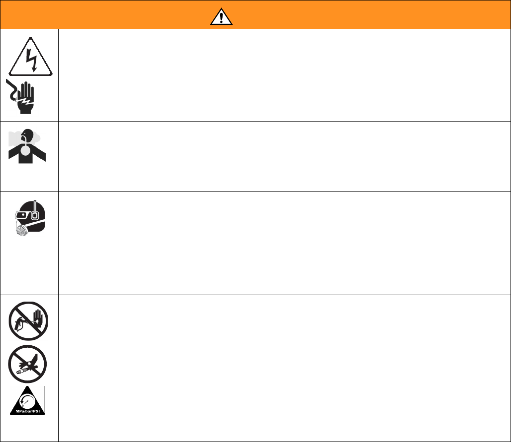
WARNING
ELECTRIC SHOCK HAZARD
Improper grounding, setup, or usage of the system can cause electric shock.
• Turn off and disconnect power cord before servicing equipment.
• Use only grounded electrical outlets.
• Use only 3-wire extension cords.
• Ensure ground prongs are intact on sprayer and extension cords.
• Do not expose to rain. Store indoors.
TOXIC FLUID OR FUMES HAZARD
Toxic fluids or fumes can cause serious injury or death if splashed in the eyes or on skin, inhaled, or swallowed.
• Read MSDS’s to know the specific hazards of the fluids you are using.
• Store hazardous fluid in approved containers, and dispose of it according to applicable guidelines.
• Always wear impervious gloves when spraying or cleaning equipment.
PERSONAL PROTECTIVE EQUIPMENT
You must wear appropriate protective equipment when operating, servicing, or when in the operating area of the
equipment to help protect you from serious injury, including eye injury, inhalation of toxic fumes, burns, and hear-
ing loss. This equipment includes but is not limited to:
• Protective eyewear
• Clothing and respirator as recommended by the fluid and solvent manufacturer
•Gloves
• Hearing protection
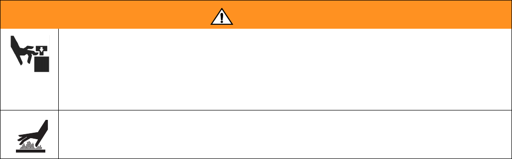
SKIN INJECTION HAZARD
High-pressure fluid from gun, hose leaks, or ruptured components will pierce skin. This may look like just a cut,
but it is a serious injury that can result in amputation. Get immediate surgical treatment.
• Engage trigger lock when not spraying.
• Do not point gun at anyone or at any part of the body.
• Do not put your hand over the spray tip.
• Do not stop or deflect leaks with your hand, body, glove, or rag.
• Do not spray without tip guard and trigger guard installed.
• Follow Pressure Relief Procedure in this manual, when you stop spraying and before cleaning, checking,
or servicing equipment.
• Tighten all fluid connections before operating equipment.
• Check hoses and couplings daily. Replace worn or damaged parts immediately.
Warnings
6312066Z
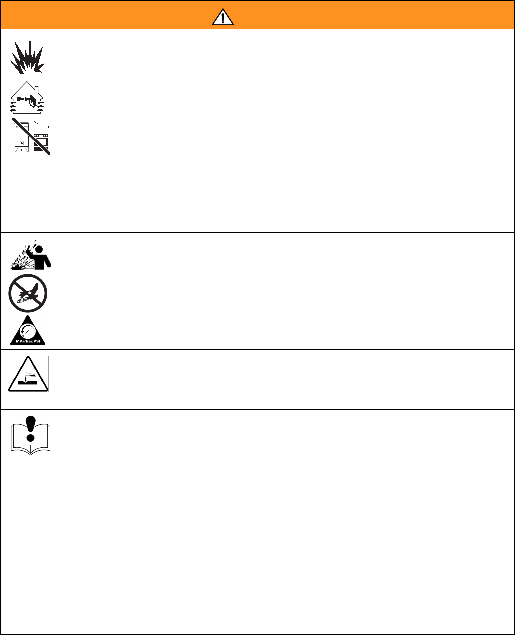
FIRE AND EXPLOSION HAZARD
Flammable fumes, such as solvent and paint fumes, in work area can ignite or explode. To help prevent fire and
explosion:
• Use and clean equipment only in well ventilated area.
• Eliminate all ignition sources; such as pilot lights, cigarettes, portable electric lamps, and plastic drop cloths
(potential static arc).
• Keep work area free of debris, including solvent, rags and gasoline.
• Do not plug or unplug power cords or turn lights on or off when flammable fumes are present.
• Ground equipment, personnel, object being sprayed, and conductive objects in work area. See Grounding
instructions.
• Use only Graco grounded hoses.
• Check gun resistance daily.
• If there is static sparking or you feel a shock, stop operation immediately. Do not use equipment until you
identify and correct the problem.
• Do not flush with gun electrostatics on. Do not turn on electrostatics until all solvent is removed from sys-
tem.
• Keep a working fire extinguisher in the work area.
THERMAL EXPANSION HAZARD
Fluids subjected to heat in confined spaces, including hoses, can create a rapid rise in pressure due to the ther-
mal expansion. Over-pressurization can result in equipment rupture and serious injury.
• Open a valve to relieve the fluid expansion during heating.
• Replace hoses proactively at regular intervals based on your operating conditions.
PRESSURIZED ALUMINUM PARTS HAZARD
Do not use 1,1,1-trichloroethane, methylene chloride, other halogenated hydrocarbon solvents or fluids contain-
ing such solvents in pressurized aluminum equipment. Such use can cause serious chemical reaction and
equipment rupture, and result in death, serious injury, and property damage.
EQUIPMENT MISUSE HAZARD
Misuse can cause death or serious injury.
• This equipment is for professional use only.
• Do not leave the work area while the equipment is energized or under pressure. Turn off all equipment and
follow Pressure Relief Procedure in this manual when the equipment is not in use.
• Do not operate the unit when fatigued or under the influence of drugs or alcohol.
• Do not exceed the maximum working pressure or temperature rating of the lowest rated system component.
See Technical Data in all equipment manuals.
• Use fluids and solvents that are compatible with equipment wetted parts. See Technical Data in all equip-
ment manuals. Read fluid and solvent manufacturer’s warnings. For complete information about your mate-
rial, request MSDS forms from distributor or retailer.
• Check equipment daily. Repair or replace worn or damaged parts immediately with genuine manufacturer’s
replacement parts only.
• Do not alter or modify equipment.
• Use equipment only for its intended purpose. Call your distributor for information.
• Route hoses and cables away from traffic areas, sharp edges, moving parts, and hot surfaces.
• Do not kink or over bend hoses or use hoses to pull equipment.
• Keep children and animals away from work area.
• Comply with all applicable safety regulations.
WARNING
Warnings
312066Z 7
MOVING PARTS HAZARD
Moving parts can pinch or amputate fingers and other body parts.
• Keep clear of moving parts.
• Do not operate equipment with protective guards or covers removed.
• Pressurized equipment can start without warning. Before checking, moving, or servicing equipment, follow
the Pressure Relief Procedure in this manual. Disconnect power or air supply.
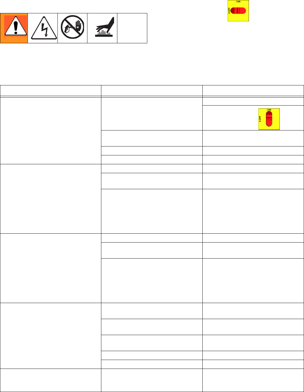
BURN HAZARD
Equipment surfaces and fluid that’s heated can become very hot during operation. To avoid severe burns, do not
touch hot fluid or equipment. Wait until equipment/fluid has cooled completely.
WARNING
Temperature Control Diagnostic Codes
8312066Z
Temperature Control Diagnostic Codes
Temperature control diagnostic codes appear on tem-
perature display.
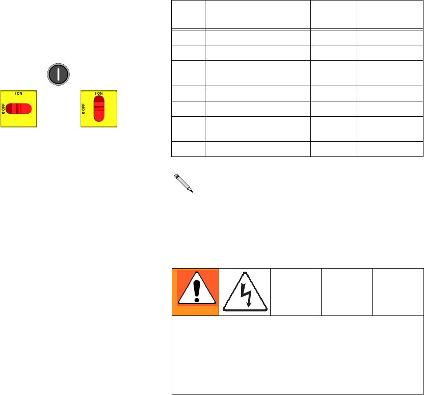
These alarms turn off heat. E99 clears automatically
when communication is regained. Codes E03 through
E06 can be cleared by pressing . For other codes,
turn main power OFF then ON to
clear.
E01: High fluid temperature
Causes of E01 Errors
• Thermocouple A or B (310) senses a fluid tempera-
ture above 230°F (110°C).
• Fluid temperature sensor (FTS) senses a fluid tem-
perature above 230°F (110°C).
• Overtemperature switch A or B (308) senses a fluid
temperature above 230°F (110°C) and opens. At
190°F (87°C) the switch closes again.
• Thermocouple A or B (310) fails, is damaged, is not
touching the heater element (307), or has a poor
connection to the temperature control board.
• Overtemperature switch A or B (308) fails in the
open position.
• The temperature control board fails to turn off any
heat zone.
• Zone power wires or thermocouples are switched
from one zone to another.
• Failed heater element where thermocouple is
installed.
• Loose wire
• On 6.0 and 10.2 kW heater models only: Jumper
wire on J1 connector, between module (3) and dis-
play (4), is loose or incorrectly wired.
Checks
Check which zone is displaying the E01 error.
1. Check that connector B is firmly plugged into tem-
perature control board (see F
IG
. 5, page 37).
2. Clean and re-plug connections.
3. Check connections between the temperature con-
trol board and overtemperature switches A and B
(308), and between temperature control board and
thermocouples A and B (310) or FTS (21) [depend-
ing on which zone is displaying E01]. See Table 5,
page 37. Ensure that all wires are securely con-
nected to connector B.
Code Code Name Alarm
Zone
Corrective
Action page
01 High fluid temperature Individual
8
02 High zone current Individual
9
03 No zone current with
hose heater on
Individual
10
04 FTS not connected Individual
10
05 Board overtemperature Individual
10
06 Communication cable
unplugged from module
Individual
10
99 Loss of communication ALL
16
For hose zone only, if FTS is disconnected at
startup, display will show hose current 0A.
Troubleshooting this equipment requires access to
parts that may cause electric shock or other serious
injury if work is not performed properly. Have a quali-
fied electrician perform all electrical troubleshooting.
Be sure to shut off all power to the equipment before
repairing.
Temperature Control Diagnostic Codes
312066Z 9
4. Remove connector B from temperature control mod-
ule, and check continuity of overtemperature
switches A and B, thermocouples A and B, or FTS
by measuring resistance across the pins on the plug
end; see T
ABLE
1.
5. Verify fluid temperature, using an external tempera-
ture sensing device.
• If temperature
is
too high (sensor reading is
229°F [109°C] or above):
6. Check if thermocouples A and B are damaged, or
not contacting the heater element, page 42.
7. To test that temperature control module turns off
when equipment reaches temperature setpoint:
a. Set temperature setpoints far below displayed
temperature.
b. Turn zone on. If temperature rises steadily,
power board is failing.
c. Verify by swapping with another power module.
See Replacing Temperature Control Assem-
bly Modules, page 38.
d. If the swapped module does not fix the problem,
the power module is not the cause.
8. Verify continuity of heater elements with an ohmme-
ter, see page 40.
E02: High zone current
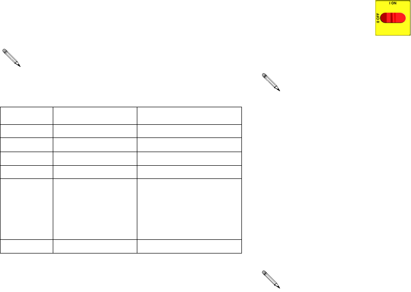
1. Turn main power OFF .
2. Relieve pressure, page 23.
3. Disconnect hose connector (D) at Reactor.
4. Using an ohmmeter, check between the two termi-
nals of the connector (D). There should be no conti-
nuity.
5. Exchange zone module with another one. Turn
zone on and check for error. If error disappears,
replace faulty module.
For hose zone:
If error still occurs, perform Trans-
former Primary Check and Transformer Secondary
Check starting on page 45.
Before doing the following checks, note which zone
(A, B, FTS, or all) has high fluid temperature.
Table 1: Sensor Connector Continuity Checks
Pins Description Reading
1 & 2 OT switch A nearly 0 ohms
3 & 4 OT switch B nearly 0 ohms
5 & 6 Thermocouple A 4-6 ohms
8 & 9 Thermocouple B 4-6 ohms
11 & 12 FTS approximately 35
ohms per 50 ft (15.2
m) of hose, plus
approximately 10
ohms for FTS
10 & 12 FTS open
Disconnect whip hose.
When there is a a high current error, the LED on
that zone’s module will turn red while the error is
displayed.
Temperature Control Diagnostic Codes
10 312066Z
E03: No zone current
1. Check for tripped circuit breaker inside electrical
cabinet or at power source for that zone. Replace
circuit breaker if it trips habitually.
2. Check for loose or broken connection at that zone.
3. Exchange zone module with another one. Turn
zone on and check for error (see page 38). If error
disappears, replace faulty module.
4. If E03 occurs for all zones, the contactor may not be
closing. Verify wiring from heater control to contac-
tor coil.
a.
Hose zone
: test hose continuity, page 43.
b. Perform Transformer Primary Check and
Transformer Secondary Check, starting on
page 45.
E04: Fluid Temperature Sensor
(FTS) or thermocouple
disconnected
1. Check temperature sensor connections to long
green connector (B) on temperature control module,
page 37. Unplug and re-plug sensor wires.
2. Test fluid temperature sensor continuity with ohm-
meter, page 8.
3. If an error occurred for the hose zone, check FTS
connections at each section of hose.
4. If an error occurred for the hose zone, test FTS by
plugging directly into machine.
5. To verify heater control module is not causing the
problem, use a wire to short-circuit the two pins cor-
responding to the FTS (red and yellow for A or B
zone, red and purple for hose). The display will
show the control heater module temperature.
6. If an error occurred for the hose zone, temporarily
use the current control mode. Refer to Reactor
Operation manual 312062.
E05: Circuit board overheated
1. Check that fan above electrical cabinet is operating.
2. Check that electrical cabinet door is properly
installed.
3. Check for obstructions blocking cooling holes in bot-
tom of electrical cabinet.
4. Clean heatsink fins behind heater control modules.
5. Ambient temperature may be too high. Allow Reac-
tor to cool by moving to a cooler location.
E06: Communication cable
unplugged
1. Unplug and re-plug cable that connects heater con-
trol module to heater module.
2. Replace communication cable if problem persists.
When a no current error occurs, the LED on the
specific zone’s module turns red when the error is
displayed.
TI10964a
FD
Each module has an on-board temperature sensor.
Heat is turned off if module temperature exceeds
185°F (85°C) within the heater module.
Motor Control Diagnostic Codes
312066Z 11
Motor Control Diagnostic Codes
Motor control diagnostic codes E21 through E29 appear
on pressure display.
There are two types of motor control codes: alarms and
warnings. Alarms take priority over warnings.
Alarms
Alarms turn off Reactor. Turn main power OFF
then ON to clear.
Warnings
Reactor will continue to run. Press to clear. A
warning will not recur for a predetermined amount of
time (varies for different warnings), or until main power
is turned OFF then ON .
Alarms can also be cleared, except for code 23, by
pressing .
Code Code Name Alarm (A) or
Warning (W)
Corrective
Action
page
21 No transducer (compo-
nent A)
A
16
22 No transducer (compo-
nent B)
A
16
23 High fluid pressure A
16
24 Pressure imbalance A/W (to
select, see
page 34)
16
25 High line voltage A
18
26 Low line voltage A
18
27 High motor temperature A
18
28 High current A
29
29 Brush wear W
19
30 Momentary loss of
communication
-
16
31 Motor control failure A
15
32 Motor control
overtemperature
A
16
99 Loss of communication -
16
Motor Control Diagnostic Codes
12 312066Z
E21: No component A
transducer
1. Check transducer A connection at J3 on motor con-
trol board, page 34, and clean contacts.
2. Reverse A and B transducer connections. If error
moves to transducer B (E22), replace transducer A,
page 36. If error does not move, replace motor con-
trol board, page 34.
E22: No component B
transducer
1. Check transducer B connection at J8 on motor con-
trol board, page 35, and clean contacts.
2. Reverse A and B transducer connections. If error
moves to transducer A (E21), replace transducer B,
page 36. If error does not move, replace motor con-
trol board, page 34.
E23: High fluid pressure
1. Relieve pressure. Verify low pressure with analog
gauges. Turn main power OFF then ON
. If error persists, do checks below.
1. Check the jumpers and the wiring. Check jumper on
motor control board J10 for E20 and E-XP1, or J7
for E30 and E-XP2, pins 7-10, page 34.
2. Remove, clean and re-install the pressure trans-
ducer leads
If the jumpers and the wiring are in good working condi-
tion and you still have the error, then you will need to
replace the “A” and “B” pressure transducers.
3. To determine if it’s the “A” or the “B” transducer, you
will need a known good Reactor pressure trans-
ducer to use as a “test” transducer. The test is done
without removing the existing pressure transducers
from the fluid manifold.
a. Unplug the “A” transducer from the Motor con-
trol board socket (page 36) and replace with
“test” transducer.
b. Turn on the Reactor master power.
• If the error is gone, turn off the Reactor main
power, remove test transducer, and replace “A”
transducer.
• If the error persists, unplug the “test” transducer
from the “A” socket, and reinstall the “A” pres-
sure transducer back into the “A” socket.
Repeat this test procedure on the “B” side.
4. If the error persists and no root cause is found
through the above testing, replace the motor control
board, page 34.
E24: Pressure Imbalance
Fast E24 Errors
Fast E24 errors occur:
• within 10 seconds of turning the pumps on, or
• as soon as you trigger the gun.
Causes of Fast E24 Errors
• one side of the gun is plugged.
• a pressure transducer has failed.
• damaged pump seals or check valve.
• no feed pressure or empty material drum
• plugged heater.
• plugged hose.
• plugged manifold.
• one PRESSURE RELIEF/SPRAY valve is leaking or
is set to PRESSURE RELIEF/CIRCULATION
If the pressure difference between components A
and B exceeds 500 psi (3.5 MPa, 35 bar), an E24
will occur. This default value is adjustable; see the
operation manual.
E24 can be an alarm or a warning, as desired. Set
DIP switch on motor control board ON for alarm,
OFF for warning. See page 34.

Motor Control Diagnostic Codes
312066Z 13
Checks for Fast E24 Errors
If gauge pressures are very close
1. Clear the error and run the unit.
2. Check plug J10 (E20/E-XP1) or J7 (E30/E-XP2) or
the jumpers 7 to 8, or 9 to 10 on the motor control
board.
3. Check pressure transducer performance:
The digital display on a Reactor always shows the
higher of the two pressures. As soon as the higher ana-
log pressure drops below the lower analog pressure the
digital display will switch to the new highest reading.
Determine which transducer is performing poorly.
1. For testing purposes only, find the dip switches
labeled SW2 on the motor control board, page 35.
Set dips witch 3 to OFF. This will allow the Reactor
to run with a pressure imbalance alarm.
2. Run the unit to build up some pressure (1000 –
1200 psi). Shut down the unit, clear the alarm and
power back up. Do not depressurize the unit.
3. Check the analog gauges to see which pressure is
higher. Check if the display pressure matches, indi-
cating that the motor control board “sees” that trans-
ducer. If not, the motor control board does not “see”
that transducer. Check the wire connections and or
replace the transducer.
4. With the pump zone off, use the pressure relief
valves to slowly relieve the “high” side pressure,
while watching the digital display and the analog
gauges. Once the higher analog gauge drops below
the lower analog pressure the motor control board
should start reading the “new” high side pressure
(because it is now the higher of the two). Continue
dropping the original “high” side pressure - the digi-
tal display should stop dropping. Repeat the pro-
cess to check the other pressure transducer.
The last test determines if the pressure transducer has
failed or if the socket on the pressure control board has
gone bad.
1. Swap the transducer plug-ins on the motor control
board. (J3 and J8 for the E-20 and E-XP1. J3 and
J5 for the E30 and E-XP1).
2. Repeat above test.
3. If the problem stays with the same side as before,
then the pressure transducer is bad.
4. If the problem switches to the other transducer, then
the problem is in the motor control boards socket.
If the gauge readings are
not
equal.
1. Clear the error and balance the pressures using the
dump valves.
2. If you cannot get the pressures to balance:
• Check for pump failure.
• Check for adequate material.
• Using the feed pump to push fluid out through the
gun manifold, check for a plugged fluid path.
• Run the unit.
• Check and clean the gun inlet screens.
• Check and clean the mix chamber “A” and “B”
impingement ports a well as the center port. Note:
Some mix chambers have counter bored holes,
and require two drill sizes to clean impingement
ports completely.
“Slow” E24:
• When spraying, gradual pressure imbalance and
eventual E24.
Possible Causes:
• One side of the Gun is partially blocked.
• The “A” or the “B” pump on the Reactor has failed.
• The “A” or the “B” feed pump has failed.
• The “A” or the “B” feed pump pressure is set too
high.
• The “A” or the “B” inlet screen is plugged.
• The hose is not heating properly.
• Kinked supply hose.
• Bottom of the drum is damaged causing a blockage
to the inlet of the feed pump.
• The drum is not vented properly.
If a fast E24 error occurs, first check the readings of
the analog gauges.
Motor Control Diagnostic Codes
14 312066Z
E25: High line voltage
Supply voltage too high. Check Reactor voltage require-
ments, page 73.
E26: Low line voltage
Supply voltage too low. Check Reactor voltage require-
ments, page 73.
E27: High Motor Temperature
1. Motor temperature too high. Reduce pressure, gun
tip size, or move Reactor to a cooler location. Allow
one hour for cooling.
2. Check fan operation.
3. Ensure there is no obstruction around the fan area
that would cause lack of airflow; ensure the
motor/fan shroud is installed.
4. Ensure the unit is being operated with the front
cover on.
5. Ensure the brush wear/over temp switch wire
assembly is plugged into J7 (E-20/E-XP1) or J6
(E-30/E-XP2) of the motor control board.
6. With the main power off, unplug the wire harness
from J7 (E-20/E-XP1) or J6 (E-30/E-XP2) on the
motor control board and install a jumper wire on
pins 1 and 2. Turn the main power back on.
If E27 is gone:
If the E27 error is gone and the motor is truly not over-
heated, then the problem can be in the motor/motor wire
harness assembly. Measure the resistance between the
two yellow wires that go to pins 1 and 2 of the motor
connector. If there is an open connection, the thermal
overload switch is open or there is a broken wire inside
the motor, or a broken wire in the motor harness.
If the E27 error code is still there, double check if pins 1
and 2 are jumpered properly. If jumpered properly, then
it would appear that the problem is with in the motor
control board.
E28: High current in motor
Check motor control board:
1. Turn the master power off.
2. Disconnect socket J4 (E-20/E-XP1) J1
(E-30/E-XP2) on the motor control board.
3. Turn the master power back on.
4. If the E28 error did not go away then there is a prob-
lem with the motor control board. Replace board,
page 34.
Check motor:
1. Check to see if the motor rotates freely.
2. Check to see if the brushes are damaged.
3. Check that the voltage going to the motor is good.
4. Check the three wire (yellow, yellow, orange) motor
connector to the motor board. A gentle tug on each
wire individually at the connector should identify the
loose wire. If a wire pulls out, bend the locking tab
on the crimp end, insert the wire until it seats and
repeat gentle tug.
5. If the above does not resolve the problem, replace
the motor, page 33.
E29: Brush Wear
1. Check for normal brush wear, which causes the
brush sensor to come in contact with the motor
commutator. Replace the brushes, page 30.
2. Check spade plug. The spade plug inside the motor
housing may be twisted and contacting the commu-
tator side of the brush sensor assembly, causing a
false alarm. Follow the orange wire coming from J7
(E-20/E-XP1), or J6 (E-30/E-XP2), up to the spade
connector on the motor. Using a flashlight, ensure
the spade plug assembly is not making contact with
the metal housing of the brush assembly.
CAUTION
Prolonged operation of motor after a brush wear
warning may result in failure of motor and motor con-
trol board.
Motor Control Diagnostic Codes
312066Z 15
3. Check wiring. The orange brush sensor wire coming
out of the brush may be routed online with the com-
mutator wiring (thick red wire), causing a false
alarm. Reroute the orange wire coming out of the
brush, away from the commutator wiring.
4. Check motor control board.
• Remove the plug in J7 (E-20/E-XP1), or J6
(E-30/E-XP2). (This will cause an E27 alarm).
• To remove the E27 alarm, use a jumper wire on the
motor control board, across the two pins that the
two yellow wires plug into. Then turn the unit on.
• The E27 as well as the E29 alarm should be gone. If
the E27 alarm is not gone double-check your
jumper.
• If the jumper is installed correctly and the E29 alarm
is still there, replace the motor control board, page
34.
E31: Motor Control Failure
(E-30 and E-XP2 only)
The E31 error code represents a motor drive error. This
indicates that the 24G881 motor control board has mal-
functioned and needs to be replaced. A motor control
board failure may also be indicated by the motor starting
up immediately upon the application of power to the sys-
tem, without pressing . This is an indication that
the output drivers of the motor control have shorted out
and are delivering full power to the motor at all times.
The cause of the failure may be one of the following con-
ditions: motor failure, capacitor failure, shorted or frayed
wiring, or inadequate power supply. Perform the follow-
ing procedure before replacing the motor control board.
1. Turn main power OFF . Disconnect power
supply.
2. Relieve pressure, page 23.
3. Perform the following inspections.
a. Motor failure: Inspect the motor commutator by
removing the top brush (see Brush Removal,
page 30). Rotate the motor, inspecting the
whole commutator for burns, pocking, or shorts
between poles. Continue rotating the motor for a
complete pump cycle, up and down, to ensure
that there is no mechanical interference or
restriction in the pump lower or gear drive sys-
tem.
b. Capacitor failure: Inspect and test the motor
start capacitor, following the Capacitor Test
instructions on page 32.
c. Shorted or frayed wiring: Inspect all wiring
connected to the motor control board and the
motor, for shorts or frayed insulation. Replace
any compromised wires with wire of the same
gauge, color. and temperature rating.
d. Inadequate power supply: Verify that the
power source is of the correct voltage and cur-
rent rating for the system, and that all phases
are properly connected. Ensure that the power
does not dip or surge during operation.
Prior to shutting down the generator, ensure
that the motor has stopped and the main dis-
connect is opened. If the generator is stopped
during operation, even due to running out of
fuel, the drop in supply voltage may cause a
motor drive failure.
Wait 5 minutes for stored voltage to discharge (E-30
and E-XP2 models only).
Communication Diagnostic Codes
16 312066Z
E32: Motor Control
Overtemperature
The E32 error code indicates a high temperature condi-
tion within the motor control board (701). This could be
caused by an abnormally high ambient temperature in
the work location, blockage of cooling vents in the cabi-
net, or the failure of the cooling fan inside the cabinet.
1. Relieve pressure, page 23. Verify low pressure with
analog gauges.
2. Turn main power OFF then ON .
If error still remains, identify cause of the overtempera-
ture condition and remedy.
Communication Diagnostic Codes
E30: Momentary loss of
communication
Communications between the display and the motor
control board or the temperature control board have
been momentarily lost. Normally, when communication
is lost, the corresponding display will show E99. The
corresponding control board will register E30 (The red
LED will flash 30 times). If communications are recon-
nected, the display can show the E30 for a short time
(no more than about two seconds). It should not be pos-
sible for E30 to be shown continuously, unless there is a
loose connection causing the display and the board to
continuously lose and regain communication.
Check all wiring between the display and the corre-
sponding control board.
E99: Loss of communication
Communications between the display and the motor
control board or the temperature control board has been
lost. When communication is lost, the corresponding
display will show E99.
1. Check all wiring between the display and the corre-
sponding control board. Pay close attention to the
wire crimping on plug J13 for each board.
2. Measure the incoming voltage to the board (it
should be ~ 230Vac).
3. If it was only receiving 1 leg of the 230Vac the board
may light up, and still not function properly. Correct
the incoming voltage problem.
Step 2 measures line voltage and should be done by a
qualified electrician. If work is not performed properly
it may cause electric shock or other serious injury.
Troubleshooting
312066Z 17
Troubleshooting
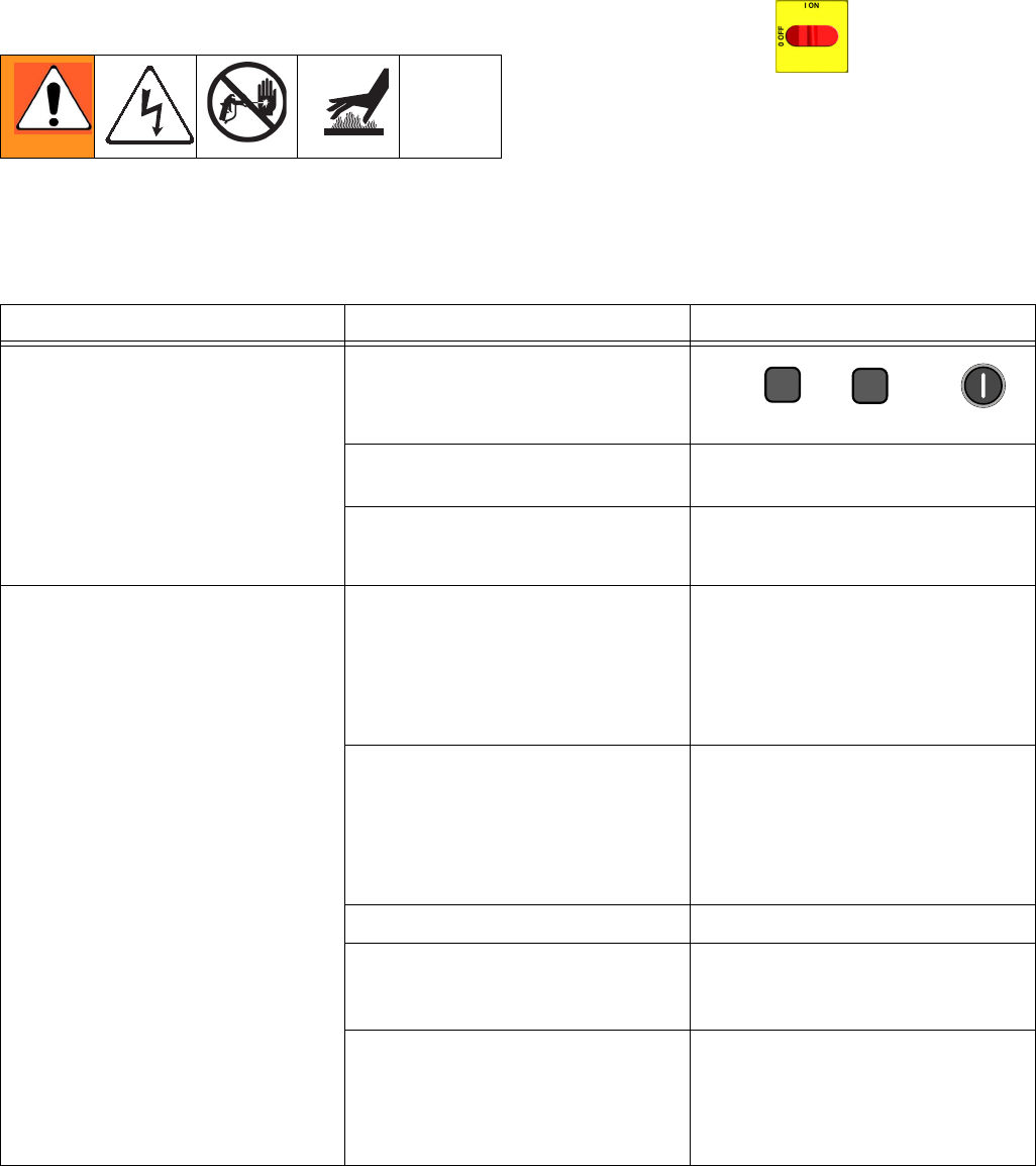
PROBLEM CAUSE SOLUTION
Reactor does not operate. No power. Plug in power cord.
Turn main power ON .
Turn circuit breakers ON, page 32.
Red stop button circuit open. Check button connections. See page
46 and electrical diagrams.
Motor does not operate. Loose connections. Check connections at motor control
board.
Circuit breaker tripped. Reset breaker (CB5), page 32.
Check 230Vac at output of breaker.
Worn brushes. Check both sides. Length must be
0.7 in. (17 mm) minimum. To replace,
page 30.
Broken or misaligned brush springs. Realign or replace, page 30.
Brushes or springs binding in brush
holder.
Clean brush holder and align brush
leads for free movement.
Shorted armature. Replace motor, page 33.
Check motor commutator for burn
spots or other damage.
Remove motor. Have motor shop
resurface commutator, if possible.
Damaged motor control board. Replace board. See page 34.
Fan not working. Blown fuse. Replace, page 36.
Loose wire. Check.
Defective fan. Replace, page 36.
Pump output low. Obstructed fluid hose or gun; fluid
hose ID too small.
Open, clear; use hose with larger ID.
Worn piston valve or intake valve in
displacement pump.
See pump manual.
Pressure setpoint too high. Reduce setpoint and output will
increase.
Fluid leak in pump packing nut area. Worn throat seals. Replace. See pump manual.
No pressure on one side. Fluid leaking from heater inlet rupture
disk (314).
Check if heater (2) and PRESSURE
RELIEF/SPRAY valve (SA or SB) are
plugged. Clear. Replace rupture disk
(314) with a new one; do not replace
with a pipe plug.
Troubleshooting
18 312066Z
Reactor Electronics
Before performing any troubleshooting procedures:
1. Relieve pressure, page 23.
2. Turn main power OFF .
3. Allow equipment to cool.
Try the recommended solutions in the order given for
each problem, to avoid unnecessary repairs. Also,
determine that all circuit breakers, switches, and con-
trols are properly set and wiring is correct before assum-
ing there is a problem.
PROBLEM CAUSE SOLUTION
Both sides of display do not
illuminate.
No power.
Plug in power cord.
Turn disconnect ON .
Low voltage. Ensure input voltage is within specifi-
cations, page 46.
Loose wire. Check connections, page 46.
Display disconnected. Check cable connections, page 46.
Temperature display does not
illuminate.
Display disconnected. Check cable connections, page 46.
Display cable damaged or corroded. Clean connections; replace cable if is
damaged.
Defective circuit board. Swap display connection to motor
control board with connection to
heater control board. If temperature
display illuminates, heater control
board is causing problem. Otherwise,
display cable or display is failing.
Pressure display does not
illuminate.
Display disconnected. Check cable connections, page 46.
Display cable damaged or corroded. Clean connections; replace cable if is
damaged.
Defective circuit board. Swap display connection to motor
control board with connection to
heater control board. If pressure dis-
play illuminates, motor control board
is causing problem. Otherwise, dis-
play cable or display is failing.
Erratic display; display turns on and
off.
Low voltage. Ensure input voltage is within specifi-
cations, page 46.
Poor display connection. Check cable connections, page 46.
Replace damaged cable.
Display cable damaged or corroded. Clean connections; replace cable if is
damaged.
Display cable not grounded. Ground cable, page 46.
Display extension cable too long. Must not exceed 100 ft (30.5 m)
Hose display reads OA at startup. FTS disconnected or not installed. Verify proper installation of FTS (see
Operation manual 312065), or adjust
FTS to desired current setting.

Troubleshooting
312066Z 19
Display does not respond properly to
button pushes.
Poor display connection. Check cable connections, page 46.
Replace damaged cable.
Display cable damaged or corroded. Clean connections; replace cable if is
damaged.
Ribbon cable on display circuit board
disconnected or broken.
Connect cable (page 46) or replace.
Broken display button. Replace, page 46.
Red stop button does not work. Broken button (fused contact). Replace, page 46.
Loose wire. Check connections, page 46.
Fan not working.
Blown fuse. Verify with ohmmeter; replace if nec-
essary (page 46).
Loose wire. Check fan wire.
Defective fan. Replace, page 46.
PROBLEM CAUSE SOLUTION
Troubleshooting
20 312066Z
Primary Heaters (A and B)
Before performing any troubleshooting procedures:
1. Relieve pressure, page 23.
2. Turn main power OFF .
3. Allow equipment to cool.
Try the recommended solutions in the order given for
each problem, to avoid unnecessary repairs. Also,
determine that all circuit breakers, switches, and con-
trols are properly set and wiring is correct before assum-
ing there is a problem.
PROBLEM CAUSE SOLUTION
Primary heater(s) does not heat.
Heat turned off.
Press or zone
keys.
Temperature control alarm. Check temperature display for diag-
nostic code, page 8.
Signal failure from thermocouple. See E04: Fluid Temperature Sen-
sor (FTS) or thermocouple discon-
nected, page 10.
Control of primary heat is abnormal;
high temperature overshoots or E01
error occurs intermittently.
Dirty thermocouple connections. Examine connection of thermocou-
ples to long green plug on heater
control board. Unplug and re-plug
thermocouple wires, cleaning off any
debris. Unplug and re-plug long
green connector.
Thermocouple not contacting heater
element.
Loosen ferrule nut (N), push in ther-
mocouple (310) so tip (T) contacts
heater element (307). Holding themo-
couple tip (T) against heater element,
tighten ferrule nut (N) 1/4 turn past
tight. See page 42 for illustration.
Failed heater element. See Primary Heaters, page 20.
Signal failure from thermocouple. See E04: Fluid Temperature Sen-
sor (FTS) or thermocouple discon-
nected, page 10.
Thermocouple wired incorrectly. See E04: Fluid Temperature Sen-
sor (FTS) or thermocouple discon-
nected, page 10. Power up zones
one at a time and verify that tempera-
ture for each zone rises.
AB
Troubleshooting
312066Z 21
Hose Heat System
Before performing any troubleshooting procedures:
1. Relieve pressure, page 23.
2. Turn main power OFF .
3. Allow equipment to cool.
Problems
Try the recommended solutions in the order given for
each problem, to avoid unnecessary repairs. Also,
determine that all circuit breakers, switches, and con-
trols are properly set and wiring is correct before assum-
ing there is a problem.
PROBLEM CAUSE SOLUTION
Hose heats but heats slower
than usual or it does not reach
temperature.
Ambient temperature is too cold. Use auxiliary hose heat system.
FTS failed or not installed correctly. Check FTS, page 10.
Low supply voltage. Verify line voltage. Low line voltage signifi-
cantly reduces power available to hose
heat system, affecting longer hose
lengths.
Hose does not maintain tem-
perature while spraying.
A and B setpoints too low. Increase A and B setpoints. Hose is
designed to maintain temperature, not to
increase it.
Ambient temperature is too cold. Increase A and B setpoints to increase
fluid temperature and keep it steady.
Flow too high. Use smaller mix chamber. Decrease pres-
sure.
Hose was not fully preheated. Wait for hose to heat to correct tempera-
ture before spraying.
Low supply voltage. Verify line voltage. Low line voltage signifi-
cantly reduces power available to hose
heat system, affecting longer hose
lengths.
Hose temperature exceeds set-
point.
A and/or B heaters are overheating
material.
Check primary heaters for either a ther-
mocouple problem or a failed element
attached to thermocouple, page 10.
Faulty thermocouple connections. Verify that all FTS connections are snug
and that pins of connectors are clean.
Examine connection of thermocouples to
long green plug on heater control board.
Unplug and re-plug thermocouple wires,
cleaning off any debris. Unplug and
re-plug long green connector on heater
control board.
Missing/damaged insulation around
FTS, causing the hose heat to be ON
constantly.
Ensure hose bundle has adequate insula-
tion evenly covering the entire length and
connection joints.
Troubleshooting
22 312066Z
Erratic hose temperature.
Faulty thermocouple connections. Verify that all FTS connections are snug
and that pins of connectors are clean.
Examine connection of thermocouples to
long green plug on heater control board.
Unplug and re-plug thermocouple wires,
cleaning off any debris. Unplug and
re-plug long green connector.
FTS not installed correctly. FTS should be installed close to end of
hose in same environment as gun. Verify
FTS installation, page 44.
Missing/damaged insulation around
FTS, causing the hose heat to be ON
constantly.
Ensure hose bundle has adequate insula-
tion evenly covering the entire length and
connection joints.
Hose does not heat.
FTS failed or is not contacting
correctly.
Check FTS, page 44.
FTS not installed correctly. FTS should be installed close to end of
hose in same environment as gun. Verify
FTS installation, page 44.
Temperature control alarm. Check temperature display or diagnostic
code, page 44.
Hoses near Reactor are warm,
but hoses downstream are cold.
Shorted connection or failed hose
heating element.
With hose heat on and temperature set-
point above displayed hose zone tem-
perature, verify voltage between
connectors at each section of hose.
Voltage should drop incrementally for
each section of hose further from Reactor.
Use safety precautions when hose heat is
turned on.
No hose heat. Loose hose electrical connections. Check connections. Repair as necessary.
Circuit breakers tripped. Reset breakers (CB1 or CB2), page 32.
Hose zone not turned on.
Press zone key.
A and B temperature setpoints too
low.
Check. Increase if necessary.
Failed temperature control board. Open cabinet. Check if board LED is
blinking. If not, check power wiring con-
nections to ensure board has power. If
board has power and LED is not blinking,
replace board, page 37.
Low hose heat. A and B temperature setpoints too
low.
Increase A and B setpoints. Hose
designed to maintain temperature, not
increase temperature.
Hose temperature setpoint too low. Check. Increase if necessary to maintain
heat.
Flow too high. Use smaller mix chamber. Decrease pres-
sure.
Low current; FTS not installed. Install FTS, see operation manual.
Hose heat zone not turned on long
enough.
Allow hose to heat up, or preheat fluid.
Loose hose electrical connections. Check connections. Repair as necessary.
PROBLEM CAUSE SOLUTION
Repair
312066Z 23
Repair
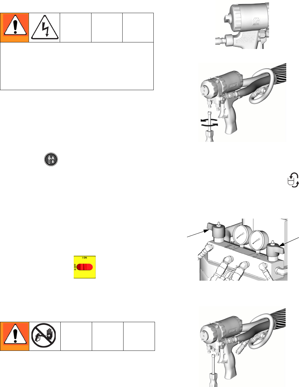
Before Beginning Repair
1. Flush if necessary; see Flushing.
2. Park component A pump.
a. Press .
b. Trigger gun until pump A stops. After fluid pres-
sure drops below 700 psi (7.9 MPa, 79 bar),
motor will run until component A pump is at bot-
tom of its stroke, then shut off.
c. Check ISO reservoir for component A pump. Fill
wet cup on component B pump. Refer to Reac-
tor Operation manual 312065.
3. Turn main power OFF .
4. Relieve pressure.
Pressure Relief Procedure
1. Relieve pressure in gun and perform gun shutdown
procedure. See gun manual.
2. Engage gun piston safety lock.
3. Close gun fluid manifold valves A and B.
4. Shut off feed pumps and agitator, if used.
5. Turn PRESSURE RELIEF/SPRAY valves (SA, SB)
to PRESSURE RELIEF/CIRCULATION .
Route fluid to waste containers or supply tanks.
Ensure gauges drop to 0.
6. Disconnect gun air line and remove gun fluid mani-
fold.
Repairing this equipment requires access to parts
that may cause electric shock or other serious injury if
work is not performed properly. Have a qualified elec-
trician connect power and ground to main power
switch terminals, see operation manual. Be sure to
shut off all power to the equipment before repairing.
ti2409a
ti2421a
ti10955a
SA SB
ti2554a
Repair
24 312066Z
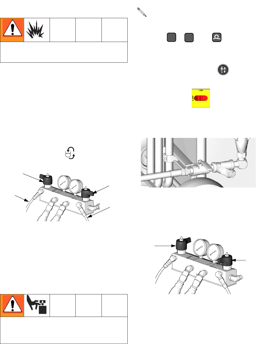
Flushing
• Flush out old fluid with new fluid, or flush out old
fluid with a compatible solvent before introducing
new fluid.
• Use the lowest possible pressure when flushing.
• All fluid components are compatible with common
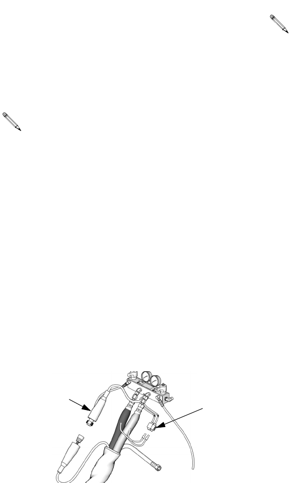
solvents. Use only moisture-free solvents.
• To flush feed hoses, pumps, and heaters separately
from heated hoses, set PRESSURE
RELIEF/SPRAY valves (SA, SB) to PRESSURE
RELIEF/CIRCULATION . Flush through bleed
lines (N).
• To flush entire system, circulate through gun fluid
manifold (with manifold removed from gun).
• To prevent moisture from reacting with isocyanate,
always leave the system dry or filled with a mois-
ture-free plasticizer or oil. Do not use water.
Pump Removal
1. Shut off , , and heat zones.
2. Flush pump.
3. If pumps are not parked, press . Trigger gun
until pumps stop.
4. Turn main power off . Disconnect power
supply.
5. Shut off both feed pumps. Close both fluid inlet ball
valves (B).
6. Turn both PRESSURE RELIEF/SPRAY valves (SA,
SB) to PRESSURE RELIEF. Route fluid to waste
containers or supply tanks. Ensure gauges drop to
0.
Flush equipment only in a well-ventilated area. Do not
spray flammable fluids. Do not turn on heaters while
flushing with flammable solvents.
Pump rod and connecting rod move during operation.
Moving parts can cause serious injury such as pinch-
ing or amputation. Keep hands and fingers away from
connecting rod during operation.
SA
SB
TI10954a
N
N
See manual 309577 for pump repair instructions.
AB
ti4147a
TI10956a
SA
SB
Repair
312066Z 25
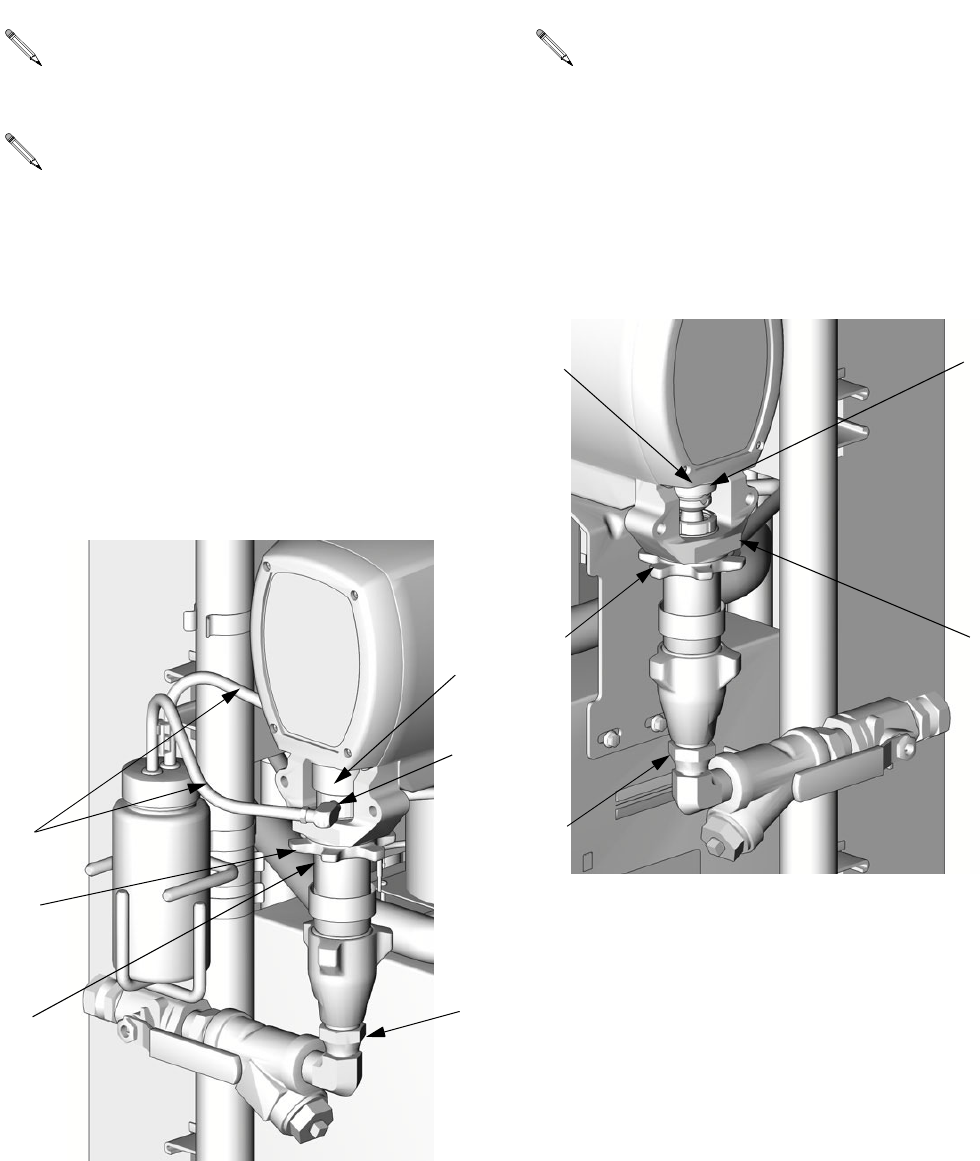
7. Disconnect fittings at fluid inlet (C) and outlet (D, out
of view). Also disconnect steel outlet tube from
heater inlet.
8. Disconnect tubes (T). Remove tube fittings (U) from
wet-cup.
9. Loosen locknut (G) by hitting firmly with a
non-sparking hammer. Unscrew pump far enough to
separate and push up finger guard (P), to expose
rod retaining pin. Push retaining wire clip up. Push
pin out. Continue unscrewing pump.
10. Disconnect fluid inlet (C) and outlet (D). Also discon-
nect steel outlet tube from heater inlet.
11. Push retaining wire clip (E) up. Push pin (F) out.
Loosen locknut (G) by hitting firmly with a
non-sparking hammer. Unscrew pump.
Use drop cloth or rags to protect Reactor and sur-
rounding areas from spills.
Steps 7-9 apply to pump A. To disconnect pump B,
go to steps 10 and 11.
TI3765a-2
C
U
G
D
T
P
Steps 10 and 11 apply to pump B.
TI3765a-1
C
F
GD
E
Repair
26 312066Z
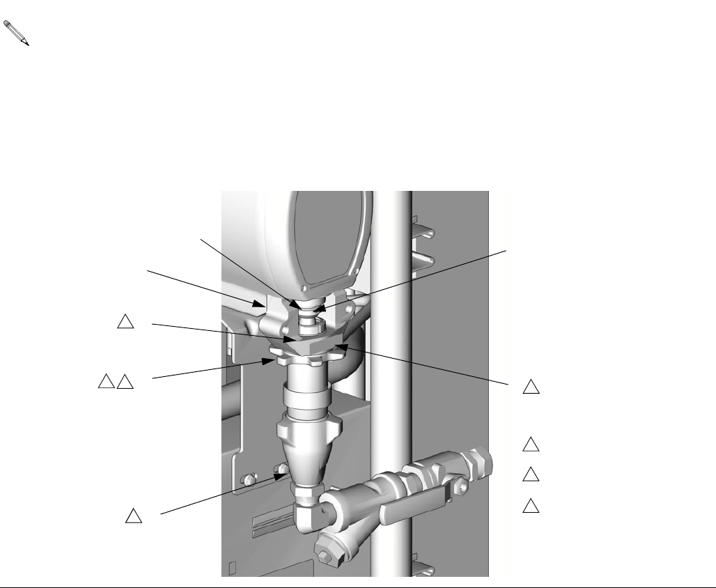
Pump Installation
1. Ensure locknut (G) is screwed on pump with flat
side up. Screw pump into bearing housing (M) until
pin holes align. Push pin (F) in. Pull retaining wire
clip (E) down.
2. Continue screwing pump into housing until fluid out-
let (D) is aligned with steel tube and top threads are
+/- 1/16 in. (2 mm) of bearing face (N).
3. Tighten locknut (G) by hitting firmly with a
non-sparking hammer.
4. Reconnect fluid inlet (C) and outlet (D).
5. Go to step 13.
Steps 1-5 supply to pump B. To reconnect pump A,
proceed to step 6.
C
D
F
E
G
M
N
1
TI3765a-1
Flat side faces up.
1
Lubricate threads with ISO
oil or grease.
2
22
2
3
Pump top threads must be
nearly flush with bearing face
(N).
3
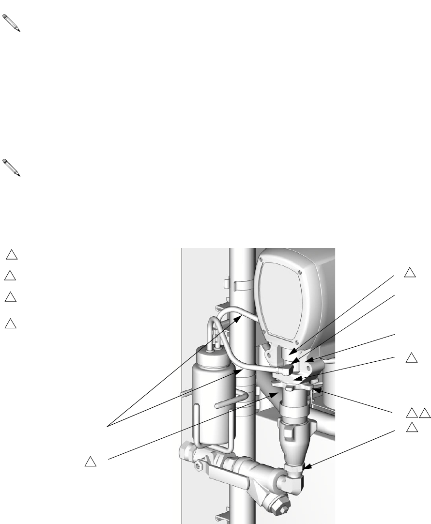
Repair
312066Z 27
6. Ensure star-shaped locknut (G) is screwed on pump
with flat side up. Carefully twist and extend displace-
ment rod 2 in. (51 mm) above wet-cup.
7. Start threading pump into bearing housing (M).
Place finger guard (P) over rod when it is accessible
through window of bearing housing. When pin holes
align, insert pin. Pull retaining wire clip down.
8. Seat finger guard (P) on wet-cup. Continue thread-
ing pump into bearing housing (M) until top threads
are +/- 1/16 in. (2 mm) of bearing face (N). Ensure
that barbed fittings at wet-cup flush ports are acces-
sible.
9. Connect component A outlet tube loosely at pump
and at heater. Line up tube, then tighten fittings
securely.
10. Tighten star-shaped locknut (G) by hitting firmly with
a non-sparking hammer.
11. Apply thin film of TSL to barbed fittings. Using two
hands, support tubes (T) while pushing straight onto
barbed fittings.
Do not let tubes kink or buckle.
Secure each tube with a wire tie between two barbs.
12. Reconnect fluid inlet (C).
13. Purge air and prime the system. See Reactor opera-
tion manual.
Steps 6-12 apply to pump A only.
Finger guard is not used on Model E-30.
C
D
T
G
M
N
1
TI3765a-2
Flat side faces up.
1
Lubricate threads with ISO oil
or grease.
2
2
2
2
3
Pump top threads must be nearly
flush with bearing face (N).
3
U
Finger guard (P) not used on
Model E-30.
4
P
4
Repair
28 312066Z
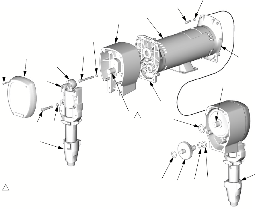
Drive Housing
Removal
1. Turn main power OFF . Disconnect power
supply.
2. Relieve pressure, page 23.
3. Remove screws (38) and motor shield (9), page 50.
4. Remove screws (209) and front cover (217).
5. Disconnect pump inlet and outlet lines. Remove
screws (213), washers (215), and bearing housing
(203).
6. Remove screws (212, 219) and washers (214) and
pull drive housing (202) off motor (201).
Installation
1. Apply grease liberally to washers (207, 208, 218),
all gears, and inside drive housing (202).
2. Install one bronze washer (208) in drive housing,
then install steel washers (207, 218) as shown.
3. Install second bronze washer (208) on gear cluster
(204) and insert gear cluster in drive housing.
4. Push drive housing (202) onto motor (201). Install
screws (212, 219) and washers (214).
5. Install bearing housing (203), screws (213), and
washers (215). Pumps must be in phase (both at
same position in stroke).
6. Install front cover (217) and screws (209).
7. Install motor shield (9) and screws (38).
Examine bearing housing (203) and connecting
rod (205). If these parts need replacing, first
remove the pump (206), page 28.
CAUTION
Do not drop gear cluster (204) when removing drive
housing (202). Gear cluster may stay engaged in
motor front end bell (R) or drive housing.
The A side drive housing includes cycle counter
switch (221). If replacing this housing, remove
pins (P) and switch. Reinstall pins and switch on
new drive housing. Switch wires connect to J10
pins 5 and 6 on motor control board, page 34.
TI3250
221
P
Drive housing crankshaft (S) must be in line with
crankshaft at other end of motor.
If bearing housing (203), connecting rod (205), or
pump (206) were removed, reassemble rod in
housing and install pump, page 26.
Repair
312066Z 29
201
202
203
204
205
206B
207208
209
212
213
214
215
217
218
219
208
214
TI3152
S
1
Crankshaft must be in line with
crankshaft at other end of motor.
1
S
R
R
206A
Repair
30 312066Z
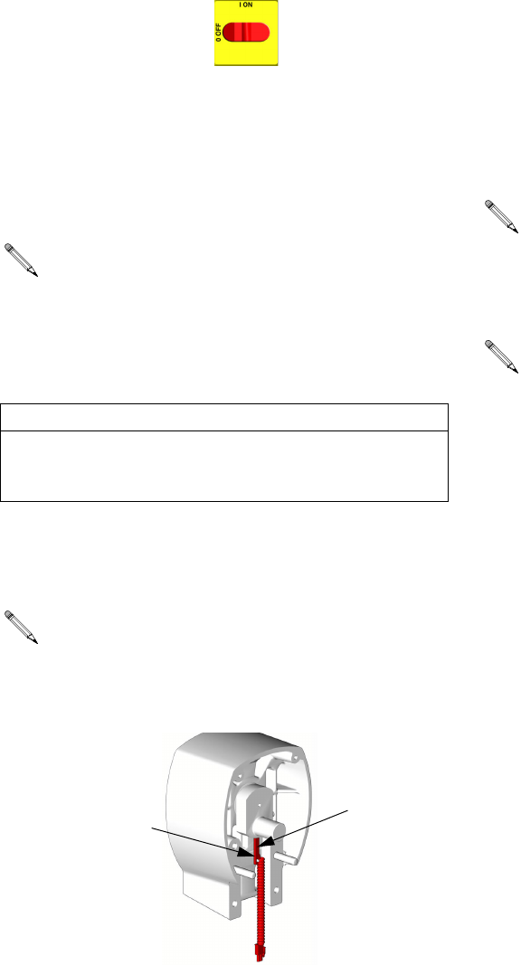
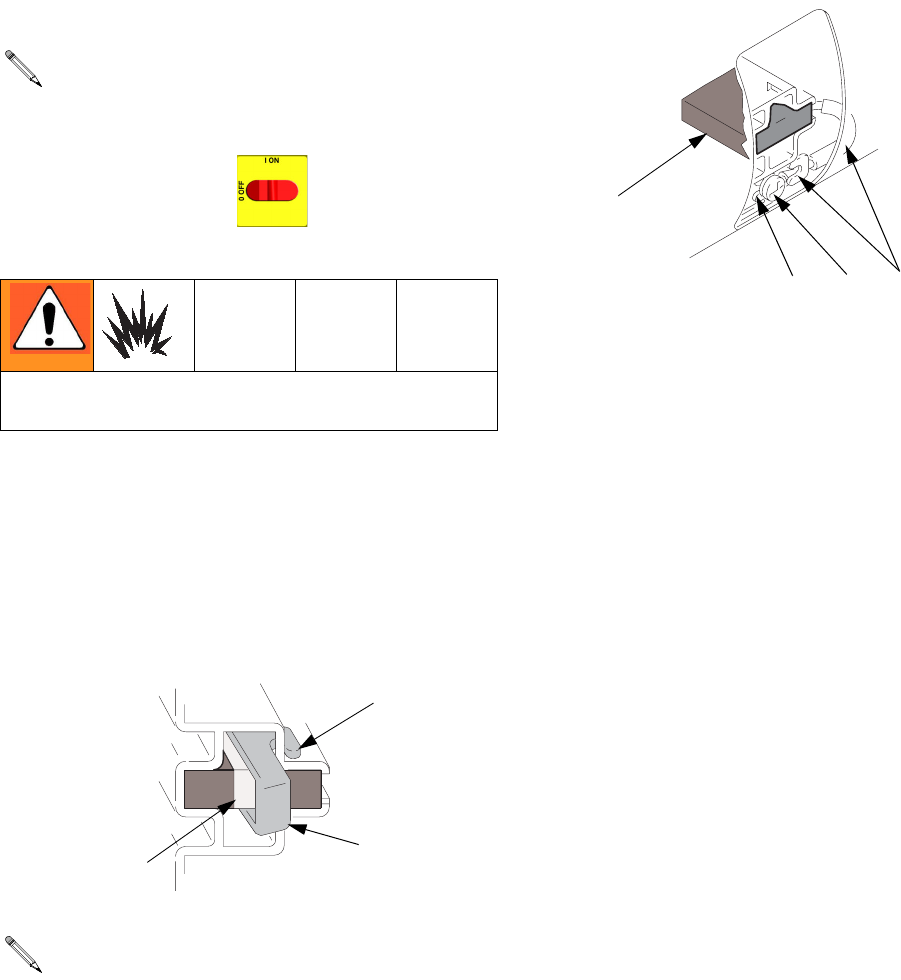
Motor Brushes
Brush Removal
1. Turn main power OFF . Disconnect power
supply.
2. Relieve pressure, page 23.
3. Remove motor cover, screw, and washers. Remove
inspection covers, screws, and gaskets from each
end of motor.
4. Push in spring clip (C) to release hooks (H) from
brush holder. Pull out clip and spring (S).
5. Loosen terminal screw (R). Pull away brush lead
(L), being careful motor lead terminal (T) remains in
place. Remove and discard brush (B).
6. Inspect commutator for excessive pitting, burning,
or gouging. Black color on commutator is normal.
Have commutator resurfaced by qualified motor
repair shop if brushes wear too quickly.
7. Repeat for other side.
Replace brushes worn to less than 1/2 in. (13
mm). Brushes wear differently on each side of
motor; check both sides. Brush Repair Kit 234037
is available.
Wait 5 min for stored voltage to discharge (E-30 and
E-XP2 models only).
One brush has a wire on top for brush wear sig-
nal. Note which side of motor it is on. Unplug at
spade connector provided.
01227-2
H
C
S
RLT
B
01227-4
Repair
312066Z 31
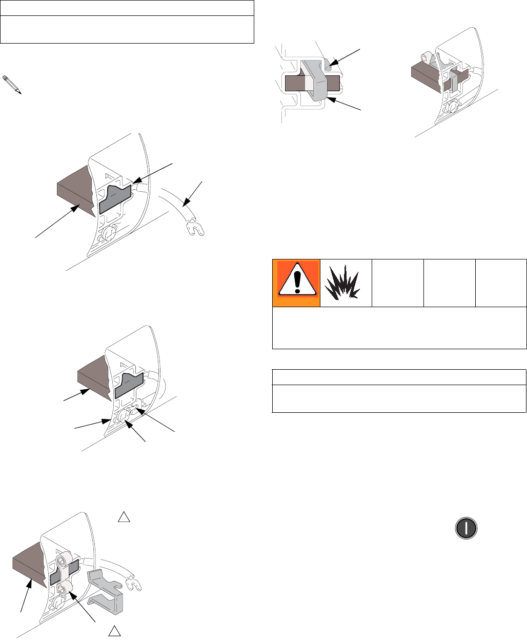
Brush Installation
1. Install new brush (B) so lead (L) is in long slot (D) of
holder.
2. Slide terminal (L) under terminal screw (R). Make
sure motor lead terminal (T) is still connected at
screw. Tighten screw.
3. Install spring (S) so it will uncoil onto brush (B), as
shown. Spring will be damaged if installed back-
wards.
4. Install spring clip (C) and push in until hooks (H)
catch slots in housing. Incorrect installation may jam
clip.
5. Reinstall brush inspection covers, gaskets, and
screws. Reinstall motor cover, screws, washers,
and drive housing/pump assemblies.
6. Test brushes with both pump pins (F) disconnected,
page 30.
Select J 1 (jog mode). Press motor to start
motor. Slowly increase jog setting to J 6. Inspect
brush and commutator contact area for excessive
arcing. Arcs should not “trail” or circle around com-
mutator surface.
Run motor for 20-30 min at J 6 to seat brushes.
CAUTION
When installing brushes, follow steps carefully.
Improper installation damages parts beyond use.
Install brush with wires on same side of motor as
before. Plug spade terminal into connector.
D
B
01227-5
L
R
L
T
B
01227-4
B
01227
Note direction of spring coil.
1
1
S
Do not touch brushes, leads, springs, or brush holders
while equipment is plugged in, to reduce the risk of
electric shock and serious injury.
CAUTION
Do not run pumps dry for more than 30 sec while
checking brushes, to avoid damaging pumps.
H
C
01227-2 01227-6
Repair
32 312066Z
Capacitor Test
1. Turn main power OFF . Disconnect power
supply.
2. Relieve pressure, page 23.
3. Locate the large, blue capacitor in the upper right
corner of the lower cabinet.
4. With a DC voltmeter, measure the voltage across
the capacitor terminals to verify that the voltage has
discharged to below 10 volts.
5. With an insulated handle screw driver, short across
the two contacts on the end of the capacitor to com-
plete discharging it. Hold for two seconds.
NOTE: A small spark may issue from the contact point.
6. Inspect the capacitor for irregularities such as
cracks, leakage, burn marks, or irregular shape.
7. Set an Ohmmeter to a range of at least 1K
Ω
and
connect the meter leads to the capacitor with the
red lead to the positive (+) terminal and the black
lead to the negative (-) terminal.
8. Observe the meter reading. It should start near 0
Ω
and climb up to 10K
Ω
, 20K
Ω
, etc., as the meter
battery charges the capacitor. This indicates a good
capacitor.
9. A reading of 0
Ω
(shorted) or O.L (open) indicates a
bad capacitor. In this case, replace the capacitor.
with the exact replacement part, item 76 on pages
55 and 56.
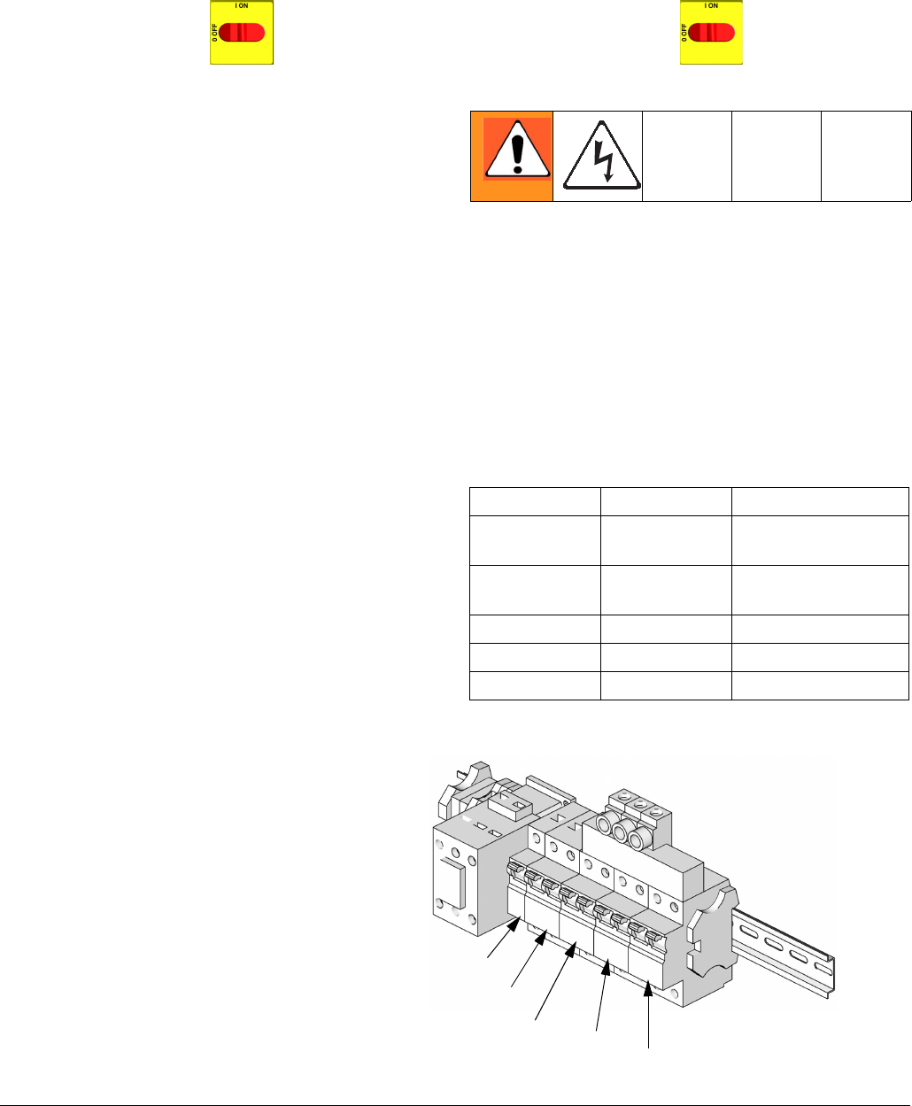
Circuit Breaker Module
1. Turn main power OFF . Disconnect power
supply. Turn circuit breakers on to test.
2. Relieve pressure, page 23.
3. Using an ohmmeter, check for continuity across cir-
cuit breaker (top to bottom). If no continuity, trip
breaker, reset, and retest. If still no continuity,
replace breaker as follows:
a. Refer to electrical diagrams and to T
ABLE
2. Dis-
connect wires and remove bad breaker.
b. Install new breaker and reconnect wires.
* Depending on model.
Table 2: Circuit Breakers, see F
IG
. 1
Ref. Size Component
909 50A Hose/Transformer
Secondary Side
911 40A Transformer
Primary
912A 25A, 40A* Heater A
912B 25A, 40A* Heater B
913 20A Motor/Pumps
F
IG
. 1. Circuit Breaker Module
ti9884a
912A
913
909
911
NOTE: To reference cables and con-
nectors, see the electrical diagrams and
the parts drawings on pages 67-68.
912B
Repair
312066Z 33
Electric Motor
Removal
1. Turn main power OFF . Disconnect power
supply.
2. Relieve pressure, page 23.
3. Remove drive housing/pump assemblies, page 28.
4. Disconnect motor cables as follows:
a. Refer to electrical diagrams. Motor control
board is on right side inside cabinet, see page
34.
b. Unplug motor power harness from connector J4
on board. See F
IG
. 2, page 35.
c. Unplug 3-pin connector J7 from board.
d. Thread cables through top of cabinet to free
motor.
5. Remove screws holding motor to bracket. Lift motor
off unit.
Installation
1. Place motor on unit. Thread motor cables into cabi-
net and into bundles as before. See electrical dia-
grams.
2. Fasten motor with screws.
3. Plug 3-pin connector J7 to board.
4. Plug motor power harness to connector J4 on
board.
5. Install drive housing/pump assemblies, page 28.
6. Return to service.
CAUTION
Motor is heavy. Two people may be required to lift.
Repair
34 312066Z
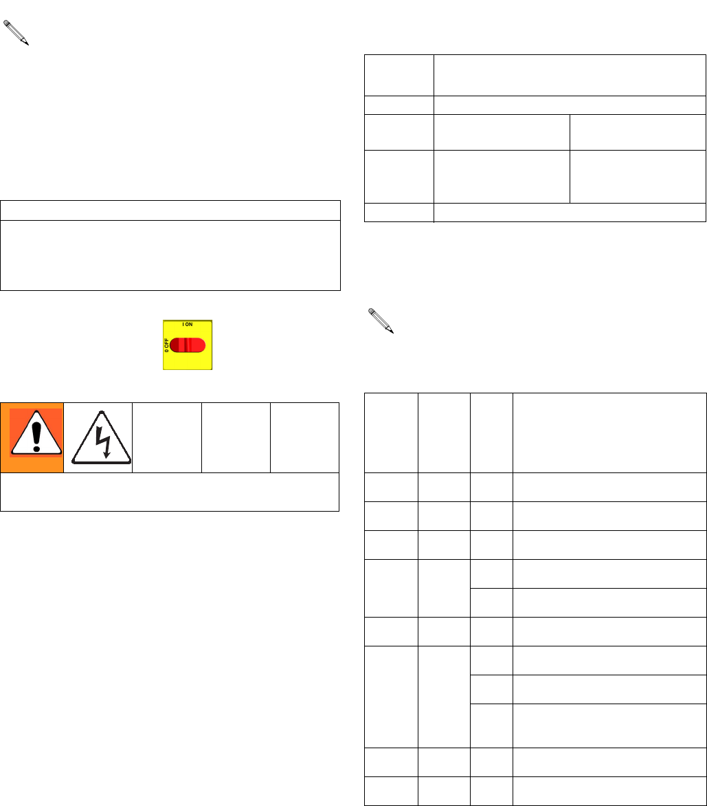
Motor Control Board
1. Turn main power OFF . Disconnect power
supply.
2. Relieve pressure, page 23.
3. Refer to electrical diagrams. Motor control board is
on right side inside cabinet.
4. Put on static conductive wrist strap.
5. Disconnect all cables and connectors from board.
6. Remove nuts (40) and take entire motor control
assembly to workbench.
7. Remove screws and take board off heatsink.
8. Set DIP switch (SW2) on new board. See T
ABLE
3
for factory settings. See F
IG
. 2 for location on board.
9. Install new board in reverse order. Apply thermal
heatsink compound to mating surfaces of board and
heatsink.
Motor control board has one red LED (D11). Power
must be on to check. See F
IG
. 2 for location. Func-
tion is:
• Startup: 1 blink for 60 Hz, 2 blinks for 50 Hz.
• Motor running: LED on.
• Motor not running: LED off.
• Diagnostic code (motor not running): LED
blinks diagnostic code, pauses, then repeats
(for example, E21=21 blinks, pause, 21 blinks).
CAUTION
Before handling board, put on a static conductive wrist
strap to protect against static discharge which can
damage board. Follow instructions provided with wrist
strap.
Wait 5 minutes for stored voltage to discharge (E-30
and E-XP2 models only).
Table 3: DIP Switch (SW2) Settings
DIP
Switch Switch Position
Switch 1 not used
Switch 2 ON for E-20 and
E-30 models
OFF for E-XP1 and
E-XP2
Switch 3 ON to enable pres-
sure imbalance
warning
OFF to enable
pressure imbalance
alarm
Switch 4 not used
Order Part 110009 Thermal Compound.
Table 4: Motor Control Board Connectors
Model
E-20
and
E-XP1
Model
E-30
and
E-XP2 Pin Description
J1 N, L n/a Main motor power
J8 J3 n/a Transducer B
J4 J1 n/a Motor output
J7 J6 1, 2 Motor thermal overload signal
3 Brush wear signal
J3 J5 n/a Transducer A
J10 J7 1-4 Not used
5, 6 Cycle switch signal
7-10 Jumper 15C866 (available in
repair kit 246961)
J12 J12 n/a Data reporting
J13 J13 n/a To display board
Repair
312066Z 35
F
IG
. 2. Motor Control Board
1
Apply 110009 thermal heatsink
compound to mating surfaces.
1
TI2576A-1
TI3153A-1
24G879 Motor Control, for E-20 and E-XP1
24G881 Motor Control, for E-30 and E-XP2
J3 (A)
J8 (B)
J1
J4
J7 J13 J10
L
J1
J6
J13
J7
J3 (B)
J5 (A)
1
D11
D7
J12
J12
SW2
SW2
N
DIP Switch (SW2) Settings
TI3178b-2
TI3178b-1
Model E-XP2
Model E-30
DIP Switch (SW2) Settings
Model E-20
Model E-XP1
TI3178b-3
TI3178b-4
ON (UP)
ON (UP)
ON (Down)
ON (Down)
Repair
36 312066Z
Transducers
1. Turn main power OFF . Disconnect power
supply.
2. Relieve pressure, page 23.
3. Refer to electrical diagrams. Motor control board is
on right side inside cabinet.
4. Disconnect transducer cables at board; see F
IG
. 2,
page 35. Reverse A and B connections and check if
diagnostic code follows; see E21: No component A
transducer, page 12.
5. If transducer fails test, thread cable through top of
cabinet. Note path as cable must be replaced in
same way.
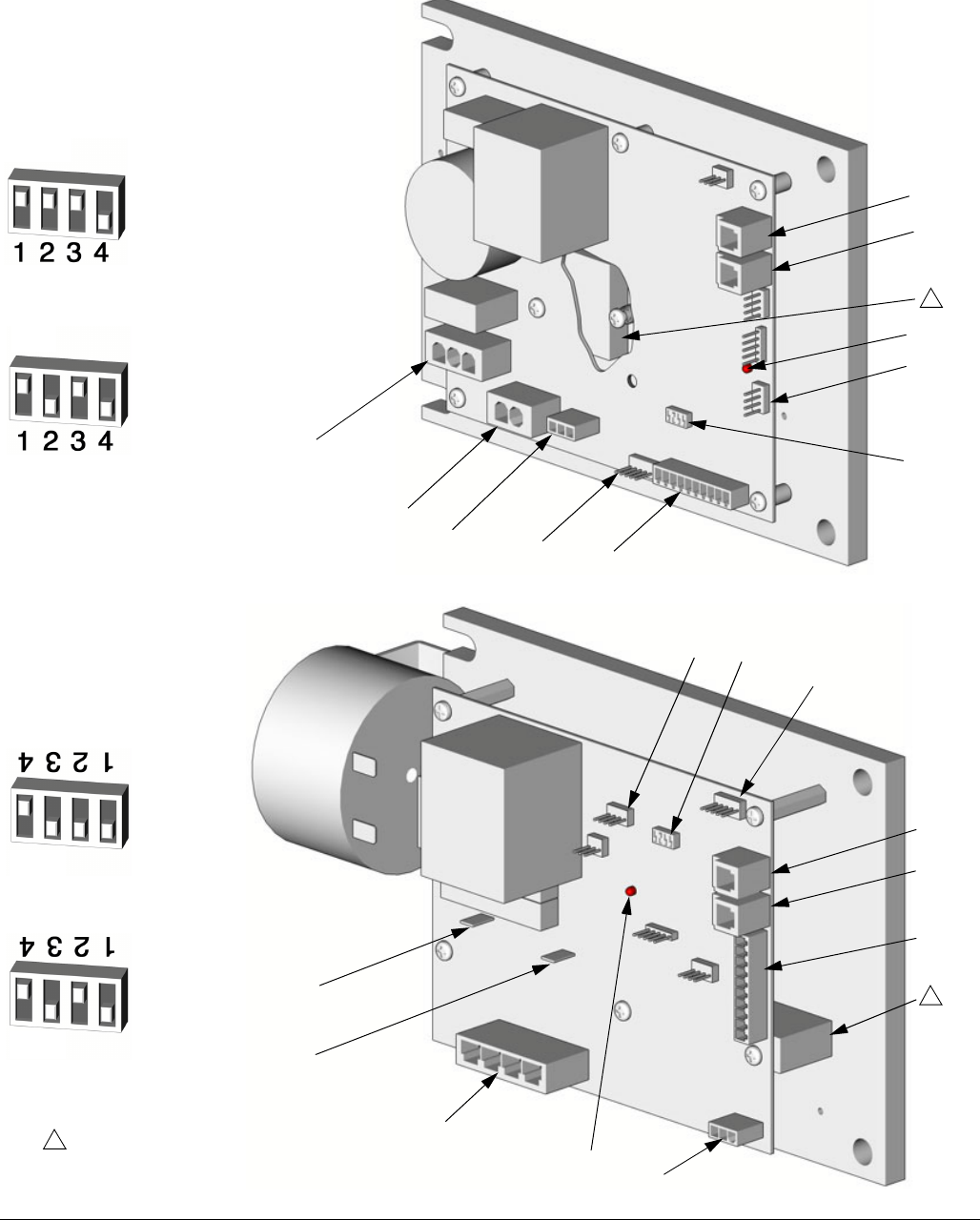
6. Install o-ring (820) on new transducer (806), F
IG
. 3.
7. Install transducer in manifold. Mark end of cable
with tape (red=transducer A, blue=transducer B).
8. Route cable into cabinet and thread into bundle as
before.
9. Connect transducer cable at board; see F
IG
. 2, page
35.
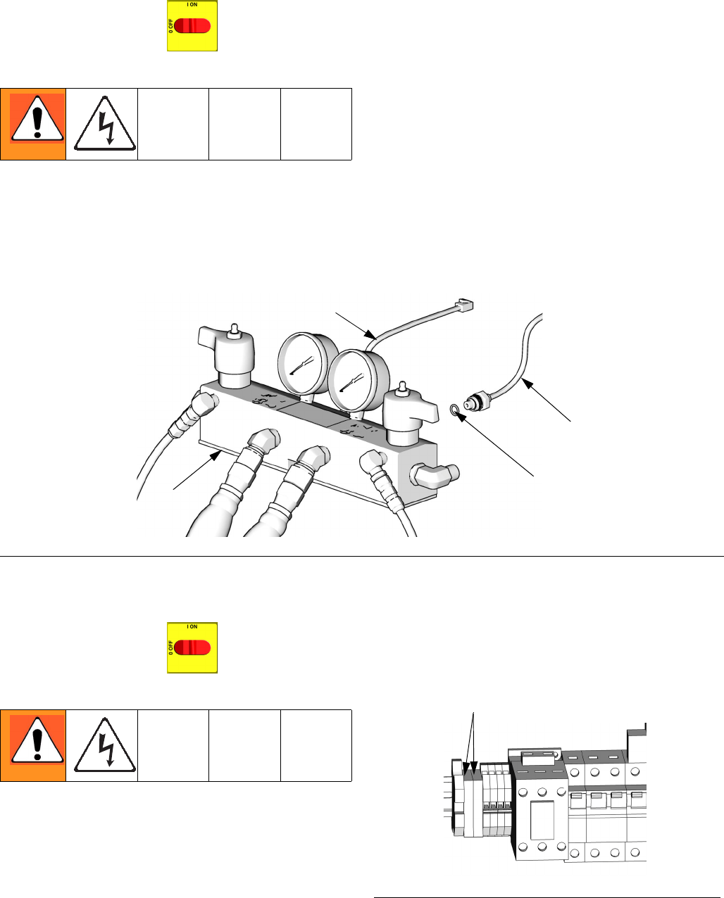
Electric Fan
1. Turn main power OFF . Disconnect power
supply.
2. Relieve pressure, page 23.
3. Check fuses (F) at left of breaker module, F
IG
. 4.
Replace if blown. If good, continue with step 4.
4. Refer to electrical diagrams. Disconnect fan wires
from fuses (F).
5. Remove fan.
6. Install fan in reverse order.
F
IG
. 3. Transducers
TI10957a
820
806 (B Side)
801
806 (A Side)
F
IG
. 4. Fan Fuses
F
ti9884a-1
Repair
312066Z 37
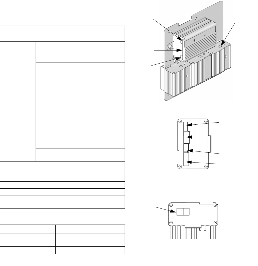
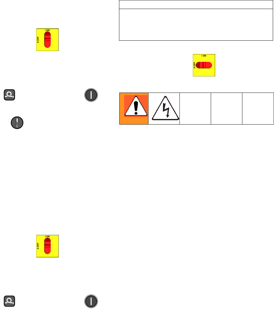
Temperature Control Module
Table 6: Temperature Power Module Connections
Table 5: Temperature Control Module Connections
Connector Description
DATA (A) Data reporting
SENSOR (B)
PIN
HOSE T/C P; FTS (purple)
12
11 HOSE T/C R; FTS (red)
10 HOSE T/C S; FTS (silver
(unshielded bare wire))
9 HEATER T/C B, Y;
Thermocouple (yellow)
8 HEATER T/C B, R;
Thermocouple (red)
7 Not used
6 HEATER T/C A, Y;
Thermocouple (yellow)
5 HEATER T/C A, R;
Thermocouple (red)
4, 3 OVERTEMPERATURE B;
Overtemperature switch B
2, 1 OVERTEMPERATURE A;
Overtemperature switch A
DISPLAY (C) Display
COMMUNICATION (D) Communication to power
boards
PROGRAM (E) Software programming
BOOT (F) Software bootloader
POWER/RELAY (G) Circuit board power input and
contactor control output
Connector Description
COMMUNICATION
(H)
Communication to control
board
POWER (J) Power to heater
F
IG
. 5: Temperature Control Module Connections
A
B
C
Bottom of Power Modules
Right Side of
Control Heater Module
D
E
F
G
ti9875a
ti9843a1
ti9843a4
H
J
Repair
38 312066Z
Test SCR Circuit
1. Test the SCR circuit in the on position:
a. Make sure everything is connected, including
the hose.
b. Turn main power ON .
c. Adjust the hose heat setpoint
above
the ambi-
ent hose temperature.
d. Turn on heat zone by pressing .
e. Hold down to view electrical current.
Hose current should ramp up to 45A. If there is
no hose current, see E03: No zone current,
page 10. If hose current exceeds 45A, see E02:
High zone current, page 9. If hose current
stays several amps below 45A, hose is too long
or voltage is too low.
2. Test the SCR circuit in the off position:
a. Make sure everything is connected, including
the hose.
b. Turn main power ON .
c. Adjust the hose heat setpoint
below
the ambi-
ent hose temperature.
d. Turn on heat zone by pressing .
e. Using a voltmeter, carefully measure the volt-
age at the hose connector. You should not get a
voltage reading. If you do, the SCR on the tem-
perature control board is bad. Replace the tem-
perature control assembly.
Replacing Temperature Control Assembly
Modules
1. Turn main power OFF . Disconnect power
supply.
2. Relieve pressure, page 23.
3. Refer to electrical diagrams; see Electrical Dia-
grams manual 312067. Temperature control assem-
bly is on left side inside cabinet.
4. Remove bolts that secure transformer assembly
and slide assembly to side in cabinet.
5. Put on static conductive wrist strap.
6. Disconnect all cables and connectors from assem-
bly; see Parts - Temperature Control, page 64.
7. Remove nuts and take entire temperature control
assembly to workbench.
8. Replace defective module.
9. Install assembly in reverse order.
CAUTION
Before handling assembly, put on a static conductive
wrist strap to protect against static discharge which
can damage assembly. Follow instructions provided
with wrist strap.

Repair
312066Z 39
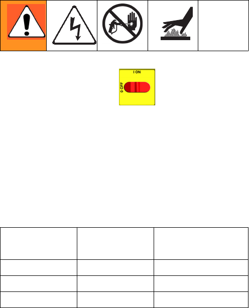
Repair
40 312066Z
Primary Heaters
Heater Element
1. Turn main power OFF . Disconnect power
supply.
2. Relieve pressure, page 23.
3. Wait for heaters to cool.
4. Remove heater shroud.
5. See F
IG
. 6. Disconnect heater element wires from
heater wire connector. Test with ohmmeter.
6. To remove heater element, first remove thermocou-
ple (310) to avoid damage, see step 7, page 42.
7. Remove heater element (307) from housing (301).
Be careful not to spill any fluid left in housing.
8. Inspect element. It should be relatively smooth and
shiny. If there is a crusted, burnt, ash-like material
adhered to element or sheath shows pitting marks,
replace element.
9. Install new heater element (307), holding mixer
(309) so it does not block thermocouple port (P).
10. Reinstall thermocouple, page 42.
11. Reconnect heater element leadwires to heater wire
connector.
12. Replace heater shroud.
Line Voltage
The primary heaters output their rated wattage at 230
Vac. Low line voltage will reduce power available and
the heaters will not perform at full capability.
Total Heater
Wattage Element Ohms
6,000 1500 30-35
7,650 2550 18-21
10,200 2550 18-21
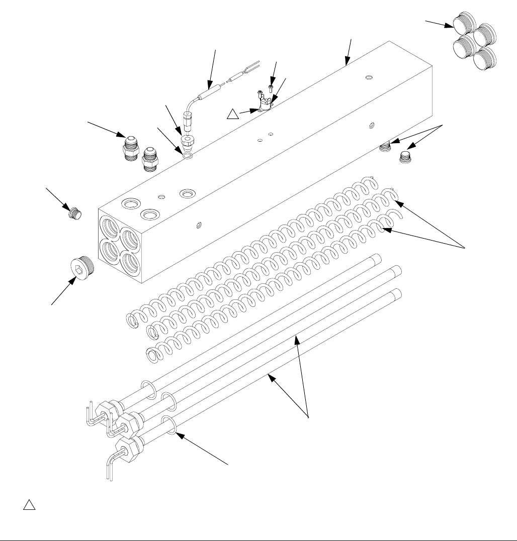
Repair
312066Z 41
F
IG
. 6. Heater (7.5 kW Single Zone Heater Shown)
303
304
309
315
308
310
311
301
r_247813_312066
305
306
Apply 110009 thermal heatsink compound.
1
1
304
313
313
307
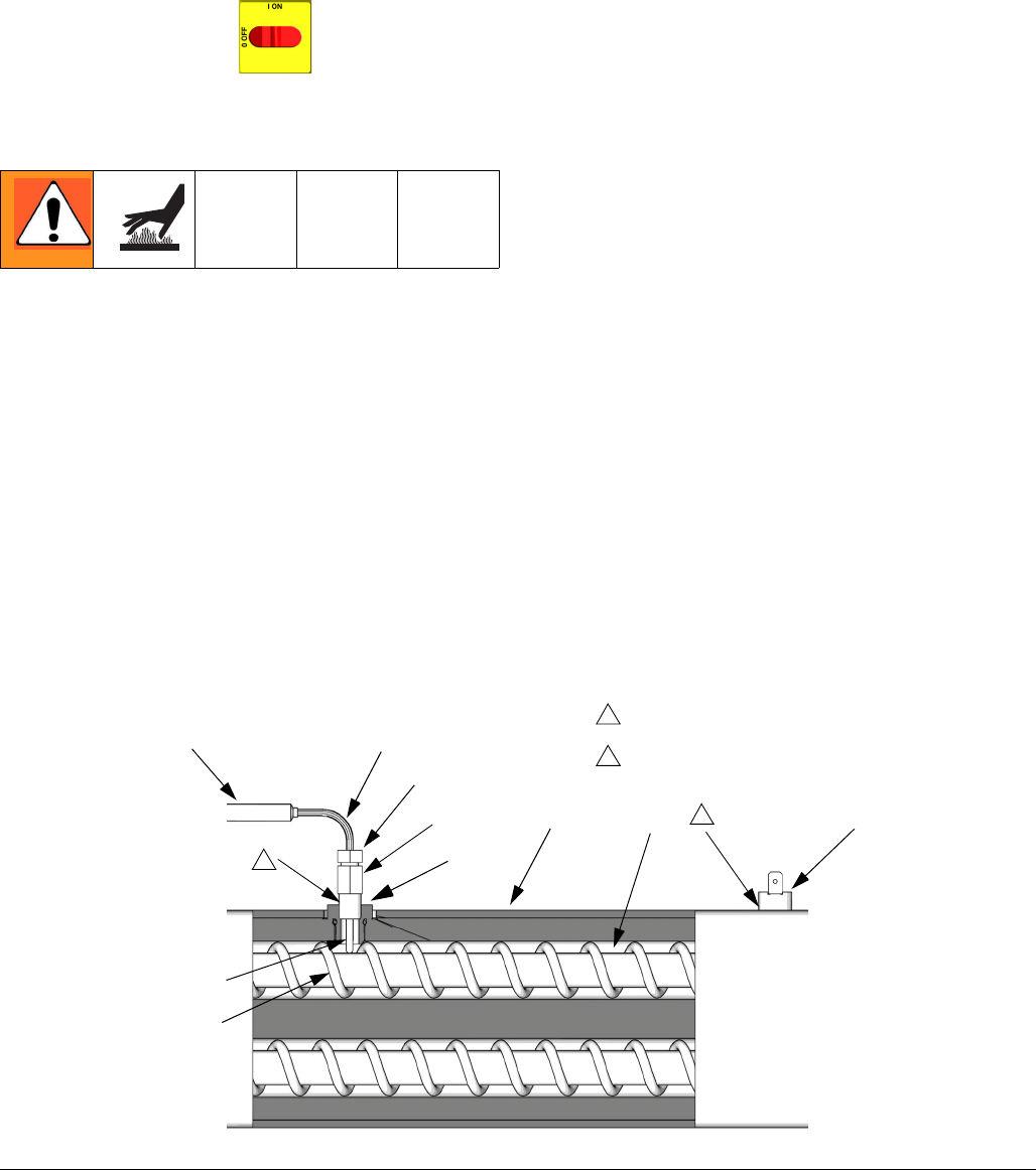
Repair
42 312066Z
Thermocouple
1. Turn main power OFF . Disconnect power
supply.
2. Relieve pressure, page 23.
3. Wait for heaters to cool.
4. Remove heater shroud.
5. Disconnect thermocouple wires from B on tempera-
ture control module. See T
ABLE
5, page 37 and F
IG
.
5, page 37.
6. Feed thermocouple wires out of cabinet. Note path
as wires must be replaced in the same way.
7. See F
IG
. 7. Loosen ferrule nut (N). Remove thermo-
couple (310) from heater housing (301), then
remove thermocouple housing (H). Do not remove
the thermocouple adapter (305) unless necessary. If
adapter must be removed, ensure that mixer (309)
is out of the way when replacing the adapter.
8. Replace thermocouple, F
IG
. 7.
a. Remove protective tape from thermocouple tip
(T).
b. Apply PTFE tape and thread sealant to male
threads and tighten thermocouple housing (H)
into adapter (305).
c. Push in thermocouple (310) so tip (T) contacts
heater element (307).
d. Holding thermocouple (T) against heater ele-
ment, tighten ferrule nut (N) 1/4 turn past tight.
9. Route wires (S) into cabinet and thread into bundle
as before. Reconnect wires to board.
10. Replace heater shroud.
11. Turn on heaters A and B simultaneously to test.
Temperatures should rise at same rate. If one
heater is low, loosen ferrule nut (N) and tighten ther-
mocouple housing (H) to ensure thermocouple tip
(T) contacts element (307).
F
IG
. 7. Thermocouple
309
301
S
N
H
T
307
Apply PTFE tape and thread sealant.
1
1
308
ti7924a
Apply 110009 thermal heatsink compound.
2
2
310
35
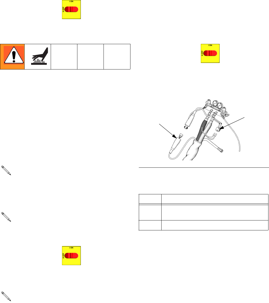
Repair
312066Z 43
Overtemperature Switch
1. Turn main power OFF . Disconnect power
supply.
2. Relieve pressure, page 23.
3. Wait for heaters to cool.
4. Remove heater shroud.
5. Disconnect one leadwire from overtemperature
switch (308), F
IG
. 7. Test across switch with ohm-
meter. Resistance must be approximately 0 ohms.
6. If switch fails test, remove wires and screws. Dis-
card failed switch. Apply thermal compound
110009, install new switch in same location on
housing (301), and secure with screws (311).
Reconnect wires.
Heated Hose
Check Hose Connectors
1. Turn main power OFF . Disconnect power
supply.
2. Relieve pressure, page 23.
3. Disconnect hose connector (D) at Reactor, F
IG
. 8.
4. Using an ohmmeter, check between the two termi-
nals of the connector (D). There should be continu-
ity.
5. If hose fails test, retest at each length of hose,
including whip hose, until failure is isolated.
Check FTS Cables
1. Turn main power OFF . Disconnect power
supply.
2. Relieve pressure, page 23.
3. Disconnect FTS cable (F) at Reactor, F
IG
. 8.
4. Test with ohmmeter between pins of cable connec-
tor.
5. If cable fails test, retest at FTS, page 44.
If wires need replacement, disconnect from temper-
ature control board. See T
ABLE
5, page 37 and F
IG
.
5, page 37.
Refer to the heated hose manual 309572 for hose
replacement parts.
Whip hose must be connected.
F
IG
. 8. Heated Hose
Pins Result
1 to 2 approximately 35 ohms per 50 ft (15.2 m) of
hose, plus approximately 10 ohms for FTS
1 to 3 infinity
TI10964a
FD
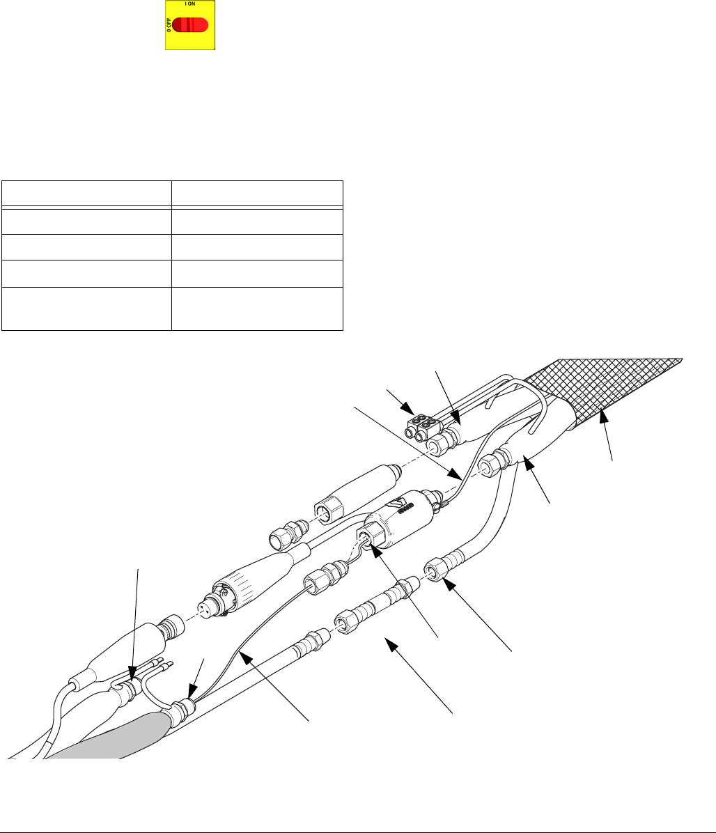
Repair
44 312066Z
Fluid Temperature Sensor (FTS)
Test/Removal
1. Turn main power OFF . Disconnect power
supply.
2. Relieve pressure, page 23.
3. Remove tape and protective covering from FTS
(21), F
IG
. 8. Disconnect hose cable (F). Test with
ohmmeter between pins of cable connector.
4. If FTS fails any test, replace FTS.
5. Disconnect air hoses (C, L), and electrical connec-
tors (D).
6. Disconnect FTS from whip hose (W) and fluid hoses
(A, B).
7. Remove ground wire (K) from ground screw on
underside of FTS.
8. Remove FTS probe (H) from component A (ISO)
side of hose.
Installation
The Fluid Temperature Sensor (FTS) is supplied. Install
FTS between main hose and whip hose. See Heated
Hose manual 309572 for instructions.
Pins Result
1 to 2 approximately 10 ohms
1 to 3 infinity
3 to FTS groundscrew 0 ohms
1 to FTS component A
fitting (ISO)
infinity
F
IG
. 9: Fluid Temperature Sensor and Heated Hoses
WLE
A
B
HC
L
ISO
A
W
B
D
K
ti17029b
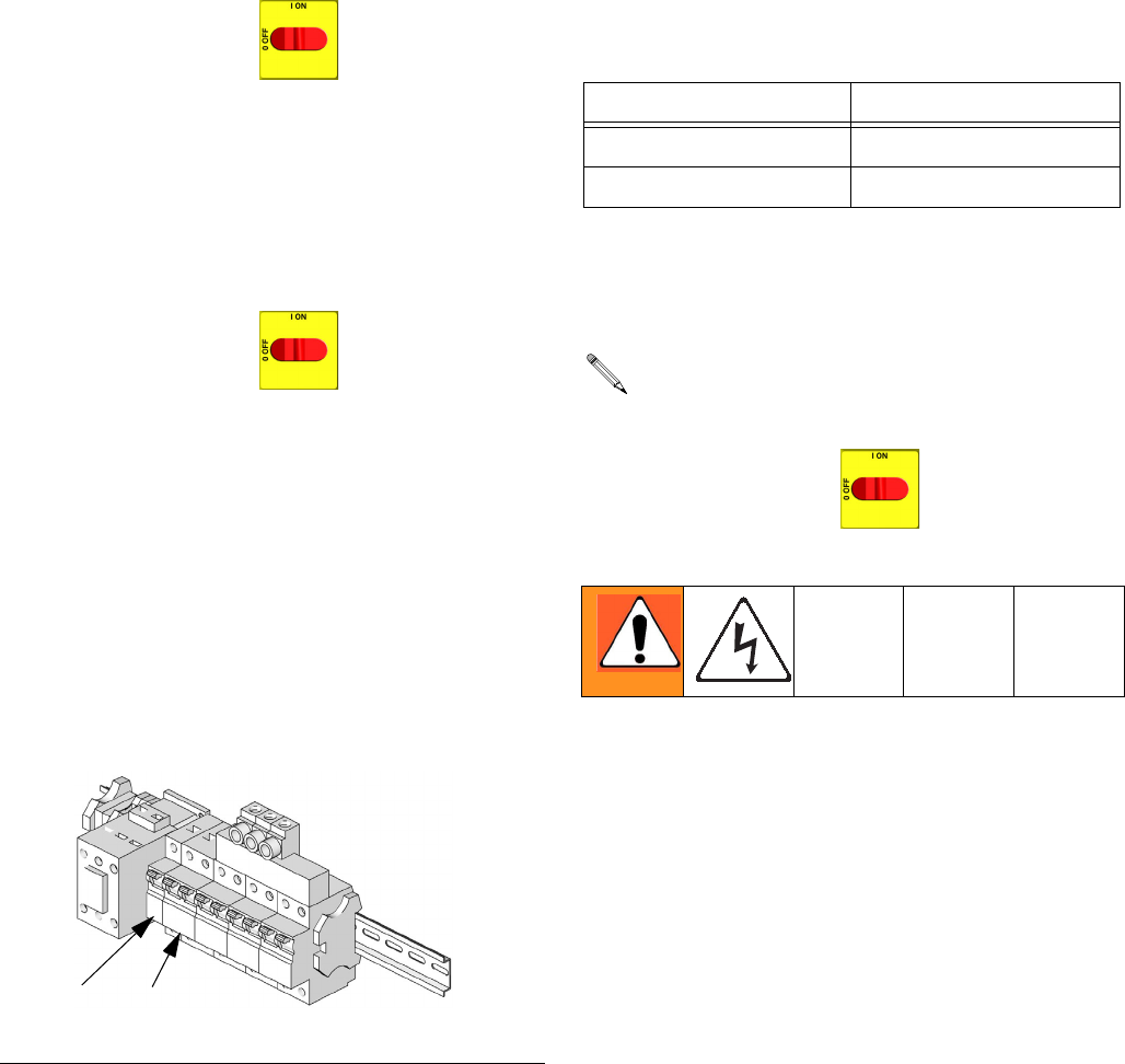
Repair
312066Z 45
Transformer Primary Check
1. Turn main power OFF .
2. Locate the two smaller (10 AWG) wires coming out
of transformer. Trace these wires back to contactor
and circuit breaker (911). Use an ohmmeter to test
for continuity between two wires; there should be
continuity.
Transformer Secondary Check
1. Turn main power OFF .
2. Locate the two larger (6 AWG) wires coming out of
transformer. Trace these wires back to large green
connector under hose control module and circuit
breaker (909). Use an ohmmeter to test for continu-
ity between two wires; there should be continuity.
If you are not sure which wire in green plug under
hose module connects to transformer, test both
wires. One wire should have continuity with the
other transformer wire in breaker (909) and the
other wire should not.
3. To verify transformer voltage, turn on hose zone.
Measure voltage from 18CB-2 to
POD-HOSE-P15-2; see Reactor Electrical Dia-
grams manual 312067.
* For 230 Vac line voltage.
Replace Transformer
1. Turn main power OFF . Disconnect power
supply.
2. Open Reactor cabinet.
3. Remove bolts holding transformer to cabinet floor.
Slide transformer forward.
4. Disconnect the transformer wires; see Reactor Elec-
trical Diagrams manual 312067.
5. Remove transformer from cabinet.
6. Install new transformer in reverse order.
F
IG
. 10: Circuit Breaker Module
909 911
ti9884a
Model Secondary Voltage
310 ft. 90 Vac*
210 ft. 62 Vac*
Use this procedure to replace transformer.
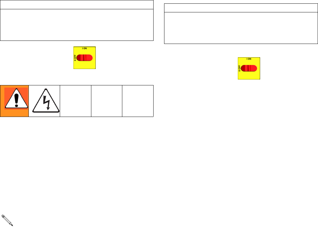
Repair
46 312066Z
Display Module
Temperature and Pressure Displays
1. Turn main power OFF . Disconnect power
supply.
2. Relieve pressure, page 23.
3. Refer to electrical diagrams.
4. Put on static conductive wrist strap.
5. Disconnect main display cable (20) at lower left cor-
ner of display module; see F
IG
. 11.
6. Remove screws (509, 510) and cover (504); see
F
IG
. 11.
7. Disconnect cable connectors (506 and 511) from
back of temperature display (501) or pressure dis-
play (502); see F
IG
. 11.
8. Disconnect ribbon cable(s) (R) from back of display;
see F
IG
. 11.
9. Remove nuts (508) and plate (505).
10. Disassemble display, see detail in F
IG
. 11.
11. Replace board (501a or 502a) or membrane switch
(501b or 502b) as necessary.
12. Reassemble in reverse order, see F
IG
. 11. Apply
medium strength thread sealant where shown. Be
sure display cable ground wire (G) is secured
between cable bushing and cover (504) with screws
(512).
Red Stop Button
1. Turn main power OFF . Disconnect power
supply.
2. Relieve pressure, page 23.
3. Refer to electrical diagrams.
4. Put on static conductive wrist strap.
5. Remove screws (509, 510) and cover (504), F
IG
.
11.
6. Disconnect button cable connectors (506) from back
of temperature display (501) and pressure display
(502).
7. Remove red stop button (506).
8. Reassemble in reverse order. Be sure display cable
ground wire (G) is secured between cable bushing
and cover (504) with screws (512).
CAUTION
Before handling board, put on a static conductive wrist
strap to protect against static discharge which can
damage board. Follow instructions provided with wrist
strap.
If replacing both displays, label temperature display
cables TEMP and pressure display cables PUMP
before disconnecting.
CAUTION
Before handling board, put on a static conductive wrist
strap to protect against static discharge which can
damage board. Follow instructions provided with wrist
strap.

Repair
312066Z 47
F
IG
. 11. Display Module
ti2574a
502
501
503
504
505
506
507
508
510
511
512
506
ti3172a
20
501a
501c
501b
502b
502c
502a
G
511
R
R
Detail of Membrane Switches and Display Boards
Temperature Display Pressure Display
Apply medium strength thread sealant.
1
1
1
1
1
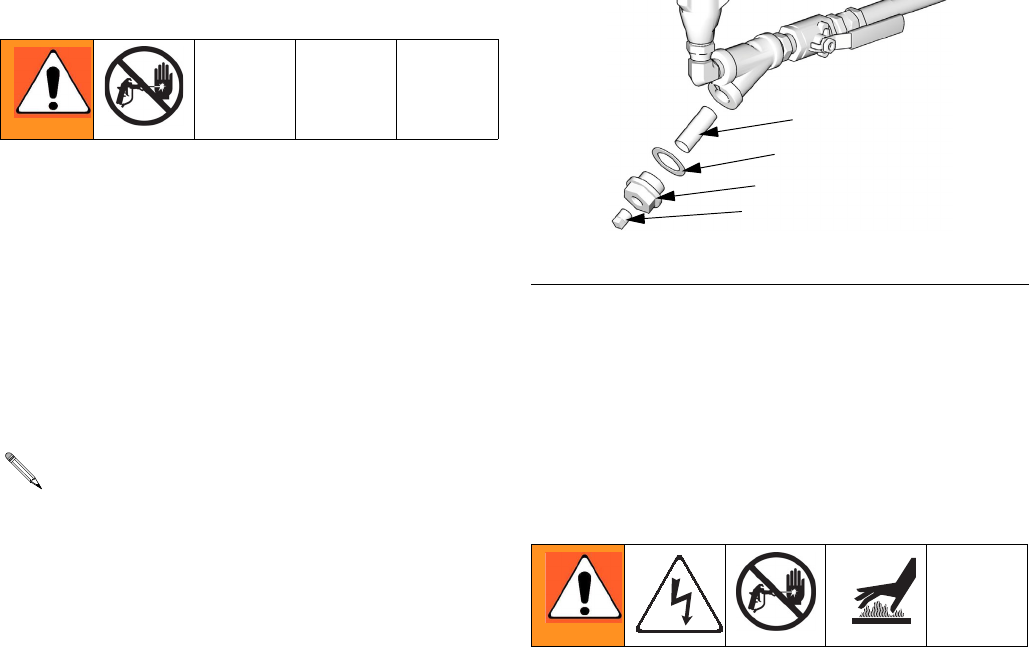
Repair
48 312066Z
Inlet Fluid Strainer Screen
The inlet strainer at each proportioning pump filters out
solid matter that can plug the inlet check valves. Inspect
the screens daily as part of the startup routine, and
clean as required.
Isocyanate can crystallize from moisture contamination
or from freezing. If the chemicals used are clean and
proper storage, transfer, and operating procedures are
followed, there should be minimal contamination of the
A-side screen.
1. Close the material supply valve at the pump inlet to
prevent material from being pumped while the
strainer plug (C) is removed.
2. Place a container under the strainer base to catch
drain off when removing the strainer plug.
3. Remove the screen (A) from the strainer manifold.
Thoroughly flush the screen with gun cleaner and
shake it dry. Inspect the screen for blockage. No
more than 25% of the mesh should be restricted. If
more than 25% is blocked, replace the screen.
Inspect the strainer gasket (B) and replace as
required.
4. Ensure the pipe plug (D) is securely screwed into
the strainer plug (C). Install the strainer plug with the
screen (A) and gasket (B) in place and tighten. Do
not overtighten. Let the gasket make the seal.
5. Open the material supply valve, ensure that there
are no leaks, and wipe the equipment clean.
6. Proceed with operation.
* Fluid filter screen (59g) replacements:
Pump Lubrication System
Check the condition of the ISO pump lubricant daily.
Change the lubricant if it becomes a gel, its color dark-
ens, or it becomes diluted with isocyanate.
Gel formation is due to moisture absorption by the pump
lubricant. The interval between changes depends on the
environment in which the equipment is operating. The
pump lubrication system minimizes exposure to mois-
ture, but some contamination is still possible.
Lubricant discoloration is due to continual seepage of
small amounts of isocyanate past the pump packings
during operation. If the packings are operating properly,
lubricant replacement due to discoloration should not be
necessary more often than every 3 or 4 weeks.
To change pump lubricant:
1. Relieve pressure, page 23.
2. Lift the lubricant reservoir (LR) out of the bracket
(RB) and remove the container from the cap. Hold-
ing the cap over a suitable container, remove the
inlet check valve and allow the lubricant to drain.
Reattach the inlet check valve to the inlet hose. See
F
IG
. 13.
Clean the A-side screen only during daily startup.
This minimizes moisture contamination by immedi-
ately flushing out any isocyanate residue at the
start of dispensing operations.
F
IG
. 12. Y Strainer Components
Part Description
180199 20 mesh (standard); 1 pack
255082 80 mesh (optional); 2 pack
255083 80 mesh (optional); 10 pack
A*
B
C
D
TI10974a
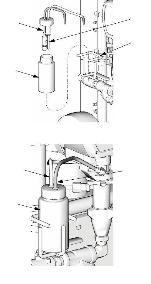
Repair
312066Z 49
3. Drain the reservoir and flush it with clean lubricant.
4. When the reservoir is flushed clean, fill with fresh
lubricant.
5. Thread the reservoir onto the cap assembly and
place it into the bracket.
6. The lubrication system is ready for operation. No
priming is required.
F
IG
. 13. Pump Lubrication System
LR
RT
ST
RB
TI10970a
TI10969a
LR
ST
RT
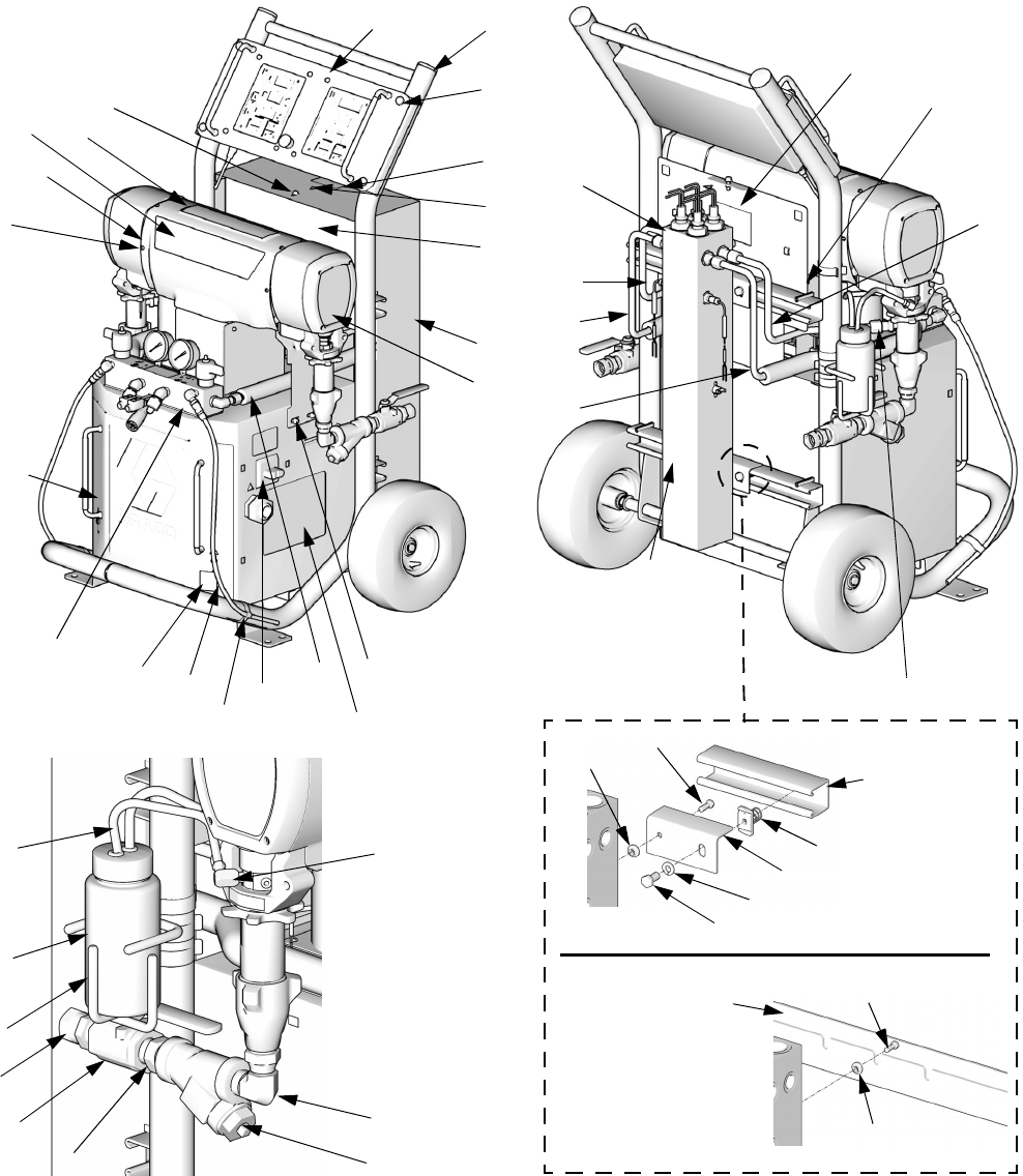
Parts
50 312066Z
Parts
Reactor Assembly (Model E-XP1 Shown)
TI10961a
57
65a
65b, 65c65d
65e
65f
72
14
17
2
41
40
45
58
59
3
7
10
44
38
9
115
TI10953a
120
15
16
90
41
41, 102 21
109,
110 113, 119
TI10960a
121
34
48
60
88
51
TI10977a
97
41
122
95
96
72
111,
112
41
122
TI18608a
Strut Channel
Style Support
Rail
Slotted U-Channel
Style Support Rail
16
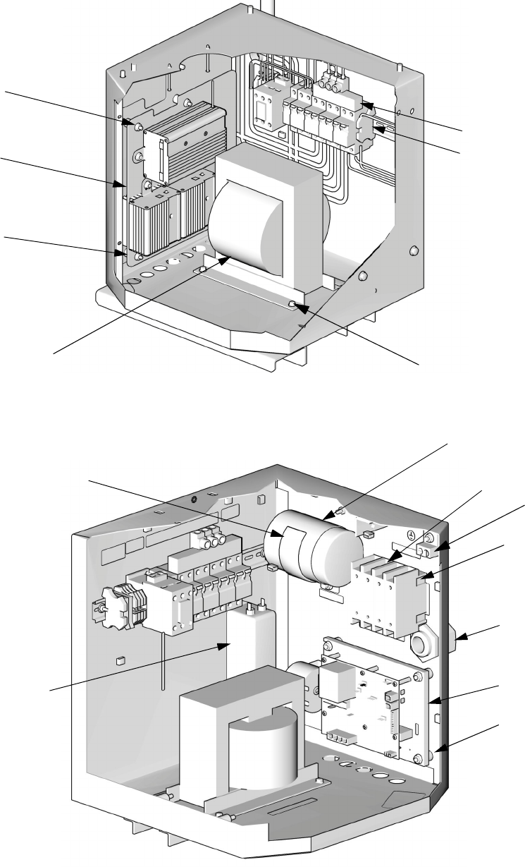
Parts
312066Z 51
8
Left Side of Cabinet
Right Side of Cabinet
42
5
123
61, 62
39, 52, 71, 73
76
33
27
6
29, 42
TI9835a
TI10968a
41
77
31, 42
36 (400V
models only)
28
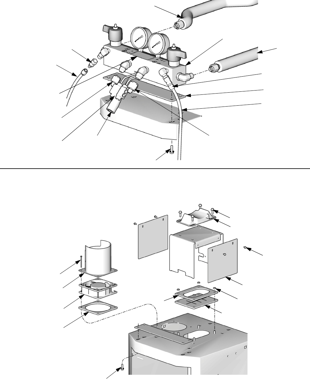
Parts
312066Z 53
Parts Used on All Models
See pages 54 through 56 for parts that vary by model.
▲
Replacement Danger and Warning labels, tags, and
cards are available at no cost.
* See quantity on referenced pages.
† Not shown.
★
Required for all A-D series models. Included in
Knob Repair Kit 258920 (purchase separately).
◆
Not required for slotted U-Channel style heater sup-
port rails.
Ref. Part Description Qty
1 FRAME; page 62 1
2 HEATER; pages 60 and 61 *
3 MODULE, proportioner; page 58 *
4 245974 DISPLAY; page 63 1
5 CONTROL, temperature; page 64 1
6 CONTROL, motor; page 65 *
7 247823 MANIFOLD, fluid; page 66 1
8 TRANSFORMER; pages 54-56 *
9 SHIELD; page pages 54-56 *
10 246976 DOOR, cabinet 1
11† 261669 SENSOR, fluid temperature 1
12 15B456 GASKET, manifold 1
13 115834 FAN 1
14 TUBE, heater component A; pages
54-56
*
15 TUBE, pump, component A; pages
54-56
*
16 TUBE, heater component B; pages
54-56
*
17 TUBE, pump, component B; pages
54-56
*
18† 247787 CABLE, overtemperature; see electrical
diagrams
1
19† 15B380 CABLE, hose control; see electrical
diagrams
1
20 15B383 CABLE, display 1
21 CONNECTOR, tube; pages 54-56 *
22 116773 CONNECTOR, plug 1
23 C38163 WASHER, lock, external tooth 1
24 15B361 BOOT, wire feed through 1
25 15B510 PLATE, cover, wire 1
26 15B360 GASKET, fan 1
27 255047 STRAIN RELIEF 1
28 MODULE, breaker; pages 54-56 *
29 116149 SPACER 8
31 117666 TERMINAL, ground 1
33
★
123969 SWITCH, disconnect 1
34
★
123967 SWITCH, main power 1
35 117723 SCREW, machine; 6-32 x 2 in. (51 mm) 4
36 SWITCH, added pole; 380V; page 54 *
38 115492 SCREW, machine; 8-32 x 0.345 in. (9
mm)
13
39 FILTER; 230V; page 54 *
40 117623 NUT, cap; 3/8-16 4
41 113796 SCREW, flanged, hex hd; 1/4-20 x 3/4
in. (19 mm)
15
42 115942 NUT, hex flange; 1/4-20 15
44 15K817 LABEL, diagnostic codes 1
45 189930 LABEL, caution 3
48
▲
189285 LABEL, caution 3
51
▲
LABEL, warning; pages 54-56 *
52 CABLE. harness, filter; pages 54-56 *
53 15B593 SHIELD, membrane switch; pack of 10 1
57 15B775 COVER, wire access 2
58 247524 COVER, heater, back 1
59 256732 COVER, heater, front 1
60
▲
15G280 LABEL, warning 1
61 113505 NUT, hex, keps; 10-24 6
62 112776 WASHER, plain; no. 10 2
65 KIT, fluid inlet 1
65a FITTING, swivel, elbow 2
65b 101078 Y-STRAINER 2
65c† 180199 ELEMENT, 20 mesh 2
65d C20487 NIPPLE, 3/4 npt 2
65e 109077 VALVE, ball; 3/4 npt (fbe) 2
65f 118459 FITTING, union, swivel; 3/4-14 npt(m) x
3/4-14 npt(f)
2
66 101078 Y-STRAINER; includes 66a 2
66a† 180199 ELEMENT, 20 mesh 1
67 109077 VALVE, ball; 3/4 npt (fbe) 2
68 C20487 NIPPLE; 3/4 npt 2
69 157785 UNION, swivel; 3/4 npt(m) x 3/4
npsm(f)
2
71 SCREW, machine; pages 54-56 *
72
◆
BRACKET. heater; pages 54-56 *
73 WASHER, lock; pages 54-56 *
76 CAPACITOR; pages 54-56 *
77 BRACKET; pages 54-56 *
86 CABLE, overtemperature, jumper;
pages 54-56
*
87 15B807 SHIELD, fan 1
88 186494 CLIP, spring 6
89 205447 COUPLING, hose 2
90 15M338 TUBE, low pressure; 1/4 in. (6 mm) ID;
3/8 in. (16 mm) OD; 4 ft (1.2 m); PTFE
1
95
◆
BOLT; hex hd; pages 54-56 *
96
◆
LOCKWASHER; 3/8; pages 54-56 *
97
◆
NUT, channel; pages 54-56 *
102 STRAP, motor; pages 54-56 *
106 117502 REDUCER; #5 x #8 JIC 1
107 117677 REDUCER; #6 x #10 JIC 1
109 246928 RESERVOIR; includes 110-119; see
309911
1
110 054826 TUBE; PTFE; 1/4 in. (6 mm) ID;
2 ft (0.6 m)
2
111 118433 VALVE, check 1
112 118432 VALVE, check 1
113 116746 FITTING, barbed 2
115 15C568 BRACKET, reservoir 1
117 206995 THROAT SEAL LIQUID; 1 qt (1 liter) 1
119 191892 ELBOW; 1/8 npt (m x f) 2
120
▲
171001 LABEL, warning 1
121 LABEL; pages 54-56 *
122 INSULATOR, heat; pages 54-56 *
123 247782 SPACER 4
124 247854 COVER, connector, module 1
125 114331 SCREW, machine; 6-32 x 0.375 in. (9.5
mm)
2
Ref. Part Description Qty

Parts
54 312066Z
Parts that Vary by Model
Use the following tables on this and the next two pages to find parts that vary by model. Find the reference number
and of part in left column and Reactor model in top row. Intersection is correct part number.
See page 53 for parts common to all models.
Ref. Description
Reactor Models
Qty
259024
E-XP1
259025
E-20
259026
E-30
259028
E-XP2
259029
E-XP1
259030
E-20
259031
E-30
259032
E-XP2
259033
E-XP1
259034
E-20
259035
E-30
259036
E-XP2
2 HEATER; pages
60 and 61 247507 247506 247507 247509
(qty: 2) 247507 247506 247507 247509
(qty: 2) 247507 247506 247507 247509
(qty: 2) 1
3MODULE, pro-
portioner; page
58
245956 245956 245957 245959 245956 245956 245957 245959 245956 245956 245957 245959 1
6CONTROL,
motor; page 65 24G879 24G879 24G881 24G881 24G879 24G879 24G881 24G881 24G879 24G879 24G881 24G881 1
8TRANS-
FORMER; 247840 247840 247812 247812 247840 247840 247812 247812 247840 247840 247812 247812 1
9 SHIELD 276878 276878 276879 276879 276878 276878 276879 276879 276878 276878 276879 276879 1
14 TUBE, heater,
component A 247920 247920 247920 247915 247920 247920 247920 247915 247920 247920 247920 247915 1
15 TUBE, pump,
component A 247912 247912 247919 247914 247912 247912 247919 247914 247912 247912 247919 247914 1
16 TUBE, heater,
component B 247918 247918 247918 247917 247918 247918 247918 247917 247918 247918 247918 247917 1
17 TUBE, pump,
component B 247913 247913 247921 247916 247913 247913 247921 247916 247913 247913 247921 247916 1
21 CONNECTOR,
tube 121310 121310 121311 121311 121310 121310 121311 121311 121310 121310 121311 121311 2
28 MODULE,
breaker; page 67 CCFFBBEEAADD1
36 SWITCH, added
pole; 380V 123968 123968 123968 123968 1
39 FILTER; 230V 117667 117667 117667 117667 117667 117667 1

Parts
312066Z 55
51▲LABEL, warning 198278 198278 198278 198278 198278 198278 1
52 CABLE, harness,
filter 15B385 15B385 15B385 15B385 15B385 15B385 1
65 KIT, fluid inlet 234366 234366 234367 234366 234366 234366 234367 234366 234366 234366 234367 234366 1
65a ELBOW, swivel;
3/4 npt(m) x 1”
npt(f)
160327 160327 118463 160327 160327 160327 118463 160327 160327 160327 118463 160327 2
71 SCREW,
machine --- --- --- --- --- --- 2
72
◆
BRACKET,
heater 247523 247523 247523 247523 247523 247523 247523 247523 247523 2
BRACKET,
heater 247523 247523 247523 4
73 WASHER, lock 103181 103181 103181 103181 103181 103181 2
76 CAPACITOR 244733 244733 244733 244733 244733 244733 1
77 BRACKET 197999 197999 197999 197999 197999 197999 1
86 CABLE, over-
temperature,
jumper
15H187 15H187 15H187 15H187 15H187 15H187 15H187 15H187 15H187
1
95
◆
BOLT; hex hd;
3/8-16 100469 100469 100469 100469 100469 100469 100469 100469 100469 2
BOLT; hex hd;
3/8-16 100469 100469 100469 4
96
◆
LOCKWASHER;
3/8 100133 100133 100133 100133 100133 100133 100133 100133 100133 2
LOCKWASHER;
3/8 100133 100133 100133 4
97
◆
NUT, channel 118446 118446 118446 118446 118446 118446 118446 118446 118446 2
NUT, channel 118446 118446 118446 4
102 STRAP, motor 15B107 15B107 15B108 15B108 15B107 15B107 15B108 15B108 15B107 15B107 15B108 15B108 1
121 LABEL
15M504 15M500 15M499 15M501 15M504 15M500 15M499 15M501 15M504 15M500 15M499 15M501
1
122 INSULATOR 167002 167002 167002 167002
(qty: 4) 167002 167002 167002 167002
(qty: 4) 167002 167002 167002 167002
(qty: 4) 2
Ref. Description
Reactor Models
Qty
259024
E-XP1
259025
E-20
259026
E-30
259028
E-XP2
259029
E-XP1
259030
E-20
259031
E-30
259032
E-XP2
259033
E-XP1
259034
E-20
259035
E-30
259036
E-XP2

Parts
56 312066Z
Parts that Vary by Model (continued)
▲
Replacement Danger and Warning labels, tags, and
cards are available at no cost.
◆
Not required for slotted U-Channel style heater sup-
port rails.
--- Not for sale.
Ref. Description
Reactor Models
Qty
259057
E-30
w/15.3kW
259058
E-30
w/15.3kW
259059
E-30
w/15.3kW
2 HEATER; pages
60 and 61 247509 247509 247509 2
3MODULE, pro-
portioner; page
58
245957 245957 245957 1
6CONTROL,
motor; page 65 24G881 24G881 24G881 1
8TRANSFORMER; 247812 247812 247812 1
9 SHIELD 276879 276879 276879 1
14 TUBE, heater,
component A 247915 247915 247915 1
15 TUBE, pump,
component A 247914 247914 247914 1
16 TUBE, heater,
component B 247917 247917 247917 1
17 TUBE, pump,
component B 247916 247916 247916 1
21 CONNECTOR,
tube 121311 121311 121311 2
28 MODULE,
breaker; page 67 FDE1
36 SWITCH, added
pole; 380V 123968 1
39 FILTER; 230V 117667 117667 117667 1
51▲LABEL, warning 198278 198278 198278 1
52 CABLE, harness,
filter 15B385 15B385 15B385 1
65 KIT, fluid inlet 234367 234367 234367 1
65a ELBOW, swivel;
3/4 npt(m) x 1”
npt(f)
118463 118463 118463 2
71 SCREW, machine --- --- --- 2
72
◆
BRACKET, heater 247523 247523 247523 4
73 WASHER, lock 103181 103181 103181 2
76 CAPACITOR 244733 244733 244733 1
77 BRACKET 197999 197999 197999 1
95
◆
BOLT; hex hd;
3/8-16 100469 100469 100469 4
96
◆
LOCKWASHER;
3/8
LOCKWASHER;
3/8 100133 100133 100133 4
97
◆
NUT, channel
NUT, channel 118446 118446 118446 4
102 STRAP, motor 15B108 15B108 15B108 1
121 LABEL 15M499 15M499 15M499 1
122 Insulator 167002 167002 167002 4
Ref. Description
Reactor Models
Qty
259057
E-30
w/15.3kW
259058
E-30
w/15.3kW
259059
E-30
w/15.3kW

Parts
312066Z 57
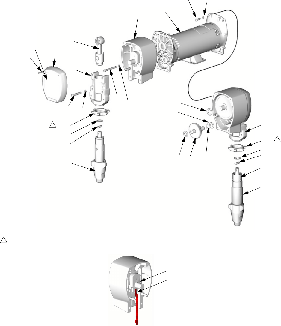
Parts
58 312066Z
Sub Assemblies
Proportioner Module
Detail of Cycle Counter Switch
TI2511a
TI3250a
245956 Module for E-20 and EXP-1
245957 Module for E-30
245959 Module for EXP-2
201
202
203
204
205
206A
*207
208
209
**210
211
212
213
214
215
216
217
218
219
*208
214
221
1
Flat side faces up.
1
220
206B 211
210**
216
1
225
224
226
Parts
312066Z 59
Proportioner Assembly
245956 Module, for E-20 and E-XP1
245957 Module, for E-30
245959 Module, for E-XP2
* Parts included in Gear Kit 244264 (245956) or
244265 (245957, 245959).
** Parts included in Connecting Rod Kit 241008
(245956) or 241279 (245957, 245959).
Ref. Part Description Qty
201 24V618 MOTOR; 245956 1
24V500 MOTOR; 245957, 245959 1
202 245968 HOUSING, drive; 245956 2
245969 HOUSING, drive; 245957, 245959 2
203 240523 HOUSING, bearing; 245956 2
241015 HOUSING, bearing; 245959 2
245927 HOUSING, bearing; 245957 2
204 244264 GEAR; includes items 207, 208;
245956
2
244265 GEAR; includes items 207, 208;
245957, 245959
2
205 241008 ROD, connecting; includes item 210;
245956
2
241279 ROD, connecting; includes item 210;
245957, 245959
2
206A 246830 PUMP, displacement, component A;
245956; see 309577
1
246831 PUMP, displacement, component A;
245959; see 309577
1
246832 PUMP, displacement, component A;
245957; see 309577
1
206B 245970 PUMP, displacement, component B;
245956; see 309577
1
245971 PUMP, displacement, component B;
245959; see 309577
1
245972 PUMP, displacement, component B;
245957; see 309577
1
207* 114699 WASHER, thrust; steel 2
208* 114672 WASHER, thrust; bronze 4
209 114418 SCREW, self-tapping; 8-32 x 1 in. (25
mm); 245956
8
114818 SCREW, self-tapping; 8-32 x 1-1/4 in.
(31 mm); 245957, 245959
8
210** 176817 CLIP, wire; 245956 2
183169 CLIP, wire; 245957, 245959 2
211 176818 PIN; 245956 2
183210 PIN; 245957, 245959 2
212 107218 SCREW, cap, socket-hd; 1/4-20 x 2-3/4
in. (70 mm); 245956
4
114686 SCREW, cap, socket-hd; 5/16-18 x
3-1/4 in. (83 mm); 245957, 245959
4
213 107210 SCREW, cap, socket-hd; 3/8-16 x 1-1/2
in. (38 mm); 245956
8
114666 SCREW, cap, socket-hd; 3/8-16 x 2-1/4
in. (57 mm); 245957, 245959
8
214 105510 WASHER, lock; 1/4; 245956 12
104008 WASHER, lock; 5/16; 245957, 245959 12
215 106115 WASHER, lock; 3/8 size 8
216 192723 NUT, retaining; 245956 2
193031 NUT, retaining; 245959 2
193394 NUT, retaining; 245957 2
217 179899 COVER; 245956 2
241308 COVER; 245957, 245959 2
218 116191 WASHER, thrust; 245956 2
116192 WASHER, thrust; 245957, 245959 2
219 100644 SCREW, cap, socket-hd; 1/4-20 x 3/4
in. (19 mm); 245956
4
101864 SCREW, cap, socket-hd; 5/16-18 x 1 in.
(25 mm); 245957, 245959
4
220 116618 MAGNET 1
221 117770 SWITCH, cycle counter 1
223 100643 SCREW, cap, socket-hd; 1/4-20 x 1 in.
(25 mm); 245956
4
102962 SCREW, cap, socket-hd; 5/16-18 x
1-1/4 in. (31 mm); 245957, 245959
4
224 104765 PLUG 2
225 15C587 GUARD, finger; 245956 1
15C588 GUARD, finger; 245959 1
226 15M507 LABEL; 245956 1
15M508 LABEL; 245957, 245959 1
Ref. Part Description Qty
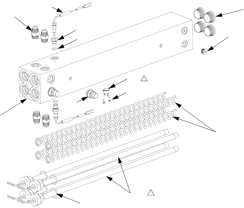
Parts
60 312066Z
Fluid Heaters
247506, 6.0 kW Fluid Heaters
247507, 10.2 kW Fluid Heaters
r_247507_312408
Apply 110009 thermal heatsink compound.
1
313
304
309
307
303
305
310
306
311
308
1
301
314
315
Ref Part Description Qty.
301 HOUSING, heater 1
303 121309 ADAPTER 4
304 15H304 PLUG 2
305 15H306 ADAPTER, thermocouple 2
306 120336 O-RING; fluoroelastomer 2
307 HEATER, immersion 4
16A110 2550W; 10.2kW heater only
16A112 1500 W; 6.0 kW heater only
308 15B137 SWITCH, overtemperature 1
309 15B135 MIXER, immersion heater 4
310 117484 SENSOR 2
311 100518 SCREW, machine, pan hd 2
313 15H305 PLUG, hollow 4
314 247520 DISC, rupture 2
315 124132 O-RINGS 4
Ref Part Description Qty.
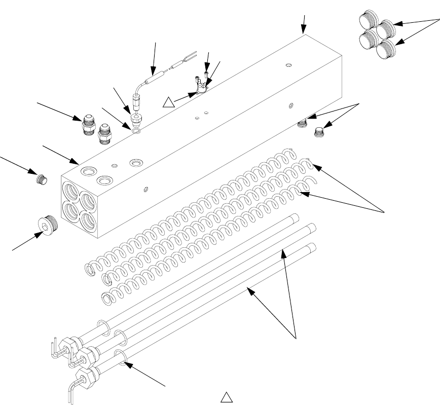
Parts
312066Z 61
7.65 kW Single Zone Fluid Heater
(Two Per Machine)
Part 247509
303
301
304
307
308
310 311
305
306
1
304
313
313
r_247813_312066
Apply 110009 thermal heatsink compound.
1
309
314
315
Ref. Part Description Qty
301 HOUSING, heater 1
303 121309 ADAPTER 2
304 15H304 PLUG 3
305 15H306 ADAPTER, thermocouple 1
306 120336 O-RING; fluoroelastomer 1
307 16A110 HEATER, immersion; 2550 W 3
308 15B137 SWITCH, overtemperature 1
309 15B135 MIXER, immersion heater 3
310 117484 SENSOR 1
311 100518 SCREW, machine, pan hd 2
313 15H305 PLUG, hollow 5
314 247520 DISC, rupture; not shown 1
315 124132 O-RING 3
Ref. Part Description Qty
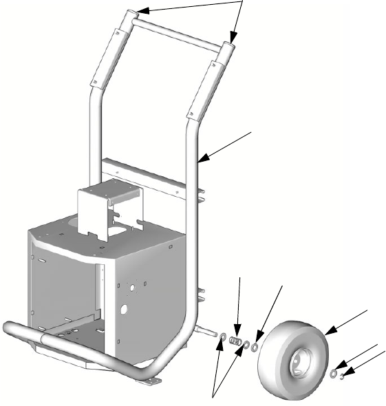
Parts
62 312066Z
Reactor Frame
TI2513a
405
401
406 404
402
404
403
407
Ref. Part Description Qty
401 FRAME 1
402 116478 WHEEL 2
403 101242 RING, retaining 2
404 116477 WASHER, flat; nylon 4
405 112125 PLUG 2
406 116411 SPRING 2
407 154636 WASHER, flat 4
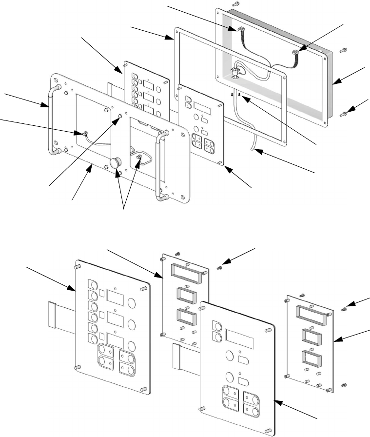
Parts
312066Z 63
Display
--- Not for sale.
ti2574a
502
501
503
504
505
506
507
508
510
511
512
506
511
ti3172a
501a
501c
501b
502b
502c502a
20 (Ref)
Ref. Part Description Qty.
501 24G884 DISPLAY, pressure; includes
501a-501c
1
501a 24G882 .BOARD, circuit 1
501b 246479 .SWITCH, membrane 1
501c 112324 .SCREW 4
502 24G883 DISPLAY, temperature; includes
502a-502c
1
502a 24G882 .BOARD, circuit 1
502b 246479 .SWITCH, membrane 1
502c 112324 .SCREW 4
503 15B293 GASKET 1
504 15B292 COVER 1
505 15B291 PLATE 1
506 246287 HARNESS, wire, red stop button 1
507 117499 HANDLE 2
508 117523 NUT, cap; 10-24 8
510 --- SCREW, machine, pan-hd; M5 x
0.8; 16 mm
4
511 15B386 CABLE, display 1
512 195853 SCREW, machine; M2.5 x 6 2
Ref. Part Description Qty.
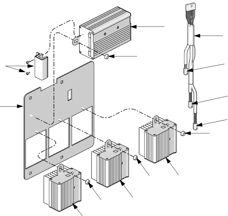
Parts
64 312066Z
Temperature Control
TI9843a
602
604
601
603
604
604
604
603
603
605
To B
Heater
Module
To A
Heater
Module
To Hose
Heater
Module
606
Ref. Part Description Qty.
601 247772 PANEL, module mounting 1
602 247827 HOUSING, control module 1
603 247828 HOUSING, heater module 3
604 115942 NUT, hex 4
605 247801 CABLE, communication 1
606 247825 KIT, cover, connector with screws 1
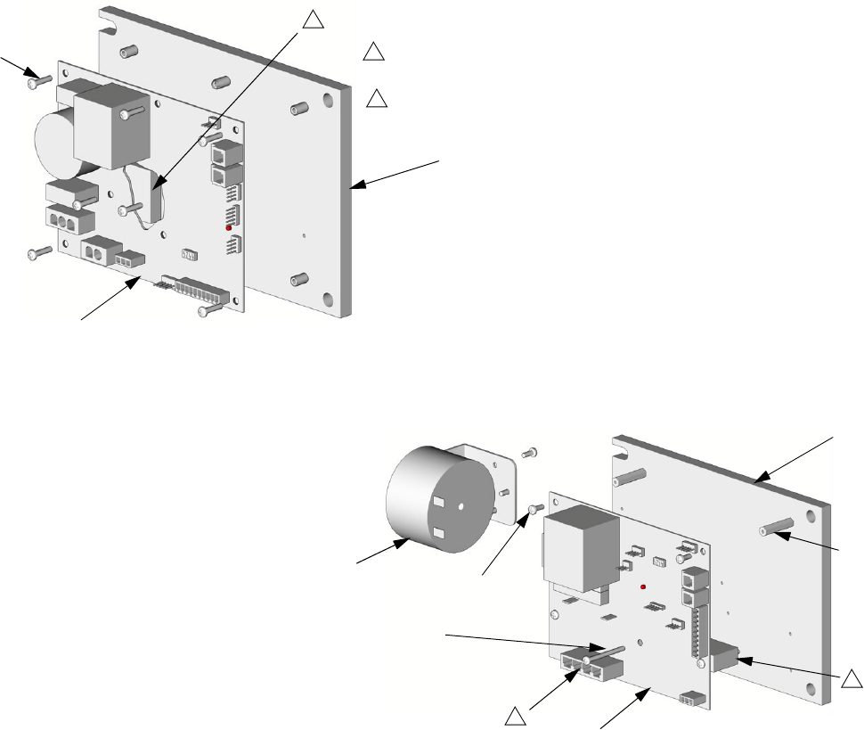
Parts
312066Z 65
Motor Control
24G879 Motor Control for E-20 and EXP-1 24G881 Motor Control for E-30 and EXP-2
--- Not for sale.
24G879 Motor Control for E-20 and EXP-1
24G881 Motor Control for E-30 and EXP-2
TI3153a
TI2576a
702
703
701
1
Apply 110009 thermal heatsink compound to mating surfaces.
1
701
702
705
703
704
707
2
Motor harness (609) plugs in here.
2
1
Ref. Part Description Qty.
701 15B297 HEAT SINK 1
702 24G878 BOARD, motor control 1
703 107156 SCREW, machine; 6-32 7
Ref. Part Description Qty.
701 16F745 HEAT SINK 1
702 --- BOARD, motor control 1
703 --- SCREW, machine;
6-32 x 3/8 in. (10 mm)
6
704 117526 SPACER 3
705 117683 SCREW, 6-32 x 1-1/2 in. (38 mm) 2
707 15C007 INDUCTOR 1
709 15B408 CABLE, harness, motor 1
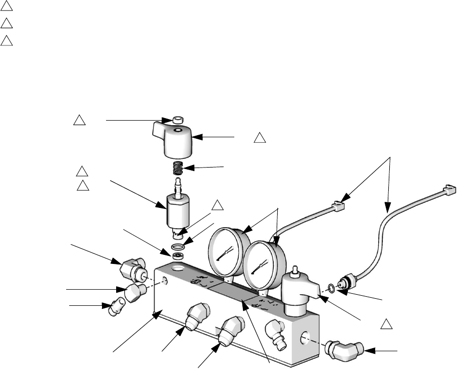
Parts
66 312066Z
Fluid Manifold
▲
Replacement Warning labels, signs, tags, and cards
are available at no cost.
† Included in the following complete valve kits*:
ISO Valve Kit (left/red handle) 255149.
Resin Valve Kit (right/blue handle) 255150.
Valve Set Kit (both handles and grease gun) 255148.
* Complete valve kits also include thread sealant.
(Purchase kits separately).
TI10959a
Torque to 355-395 in-lb (40.1-44.6 N•m).
Apply sealant (113500) to threads.
Valve must be closed with handle position as shown on drawing.
** Apply PTFE tape or thread sealant to tapered threads.
1
2
3
808
806
818
802
803
805
814
815
804
801 812
813 817
814
807
816
1
2
3
2
3
3
802a
802b
Ref. Part Description Qty.
801 247837 MANIFOLD, fluid 1
802† 247824 VALVE, drain cartridge 2
802a† 158674 . O-RING 1
802b† 247779 . SEAL, seat, valve 1
803 102814 GAUGE, pressure, fluid 2
804 162453 FITTING, 1/4 npsm x 1/4 npt 2
805 24K999 TRANSDUCER, pressure, control 2
806 247788 HANDLE, red 1
807 247789 HANDLE, blue 1
808† 112309 NUT, hex, jam 2
812 117556 NIPPLE, #8 JIC x 1/2 npt 1
813 117557 NIPPLE, #10 JIC x 1/2 npt 1
814 121312 ELBOW, 90 degrees 2
815 100840 ELBOW, street; 1/4 npsm x 1/4 npt 2
816 111457 O-RING, PTFE 2
817▲189285 LABEL, caution 1
818† 150829 SPRING, compression 2
Ref. Part Description Qty.
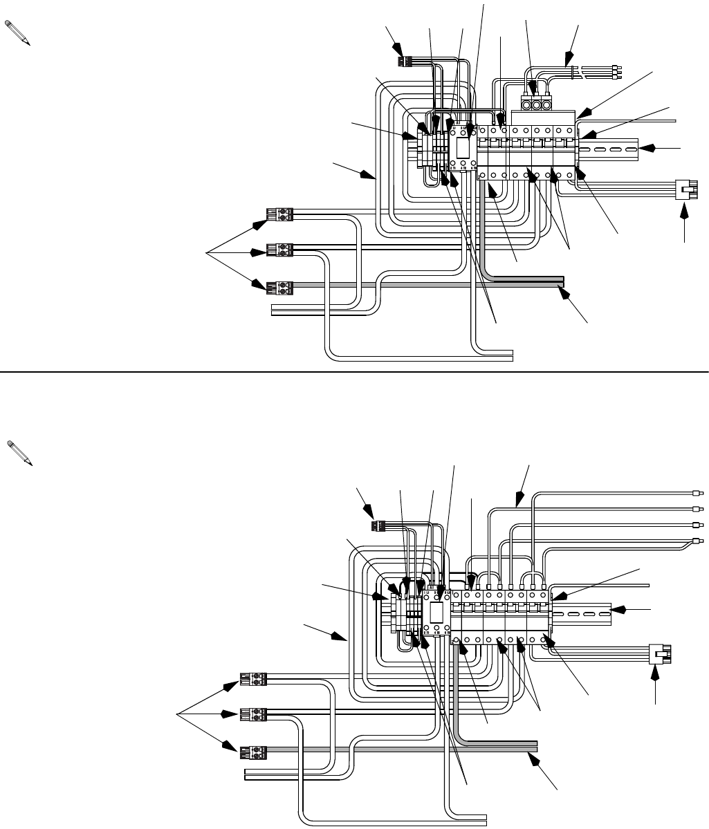
Parts
312066Z 67
Circuit Breaker Modules
178CB
187CB
197CB 172CB
238CR
172CB
197CB
187CB
178CB
238CR
168BR
B - 400V, 3 Phase Circuit Breaker Modules
(E-20, E-XP1)
For wiring and cable connections, refer to electrical
diagrams manual 312067, supplied. See page 70
for parts.
A - 230V, 3 Phase Circuit Breaker Modules
(E-20, EXP-1)
For wiring and cable connections, refer to electrical
diagrams manual 312067, supplied. See page 70
for parts.
918
907
909 912
913 919
901
908
915
917
914
916
911
910
906
905
920
902
903, 904
918
907
909 912
913 919
901
908
917
916
911
910
906
905
920
902
903, 904
922
922
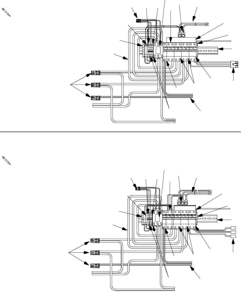
Parts
68 312066Z
#"
#"
#"
#"
2#
"2
172CB
197CB
187CB
178CB
238CR
168BR
C - 230V, 1 Phase Circuit Breaker Modules
(E-20, EXP-1)
For wiring and cable connections, refer to electrical
diagrams manual 312067, supplied. See page 70
for parts.
918
907
909 912
913 919
901
908
915
917
914
916
911
910
906
905
920
902
903, 904
D - 230V, 3 Phase Circuit Breaker Modules
(E-30, EXP-2)
For wiring and cable connections, refer to electrical
diagrams manual 312067, supplied. See page 70
for parts.
918
907
909 912
913
901
908
915
917
914
916
911
910
906
905
920
902
903, 904
919
922
922
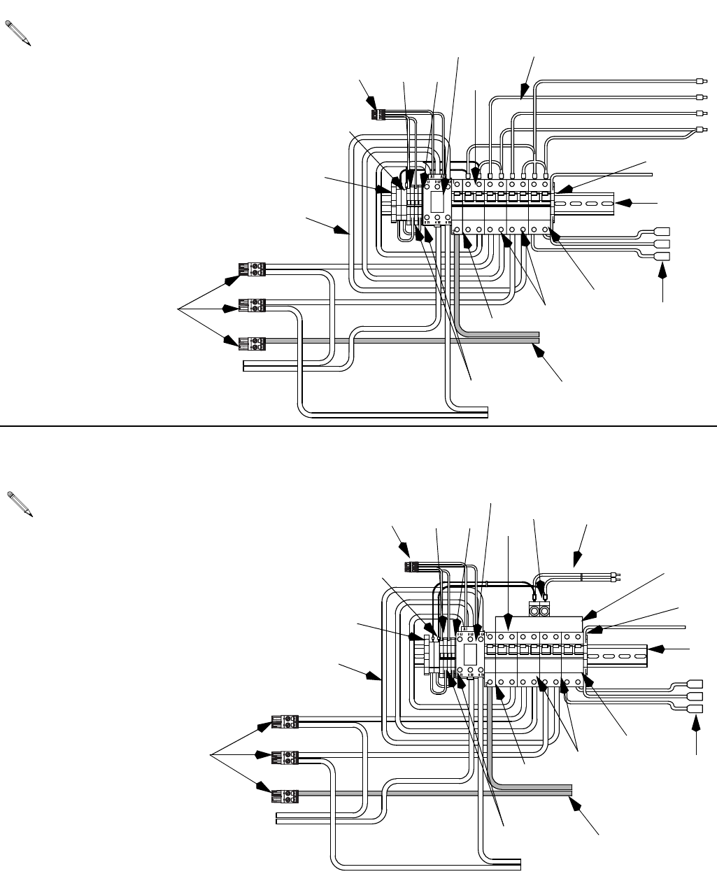
Parts
312066Z 69
#"
#"
#"
#"
2#
"2
#"
#"
#" #"
2#
E - 400V, 3 Phase Circuit Breaker Modules
(E-30, E-XP2)
For wiring and cable connections, refer to electrical
diagrams manual 312067, supplied. See page 70
for parts.
918
907
909 912
913
901
908
917
916
911
910
906
905
920
902
903, 904
F - 230V, 1 Phase Circuit Breaker Modules
(E-30, EXP-2)
For wiring and cable connections, refer to electrical
diagrams manual 312067, supplied. See page 70
for parts.
918
907
909 912
913
919
901
908
915
917
914
916
911
910
906
905
920
902
903, 904
919
922
922

Parts
70 312066Z
Circuit Breaker Modules Parts List
--- Not for sale.
Ref. Description
Breaker Modules
Qty
E-20 and EXP-1 Models E-30 and EXP-2 Models
A
230V,
3 phase
B
400V,
3 phase
C
230V,
1 phase
D
230V,
3 phase
E
400V,
3 phase
F
230V,
1 phase
901 RAIL, mounting 255028 255028 255028 255028 255028 255028 1
902 CLAMP, block, end 255045 255045 255045 255045 255045 255045 1
903 HOLDER, fuse terminal, block 255043 255043 255043 255043 255043 255043 2
904 FUSE 255023 255023 255023 255023 255023 255023 2
905 TERMINAL, block 255042 255042 255042 255042 255042 255042 4
906 TERMINAL, end cover --- --- --- --- --- --- 1
907 BRIDGE, plug in, jumper 255044 255044 255044 255044 255044 255044 2
908 BLOCK, terminal ground 255046 255046 255046 255046 255046 255046 1
909 BREAKER, 1 pole, 50A 255026 255026 255026 255026 255026 255026 1
910 CONTACTOR, relay, 65A 255022 255022 255022 255022 255022 255022 1
911 BREAKER, 2 phase, 40A 247768 247768 247768 247768 247768 247768 1
912 BREAKER, 2 phase, 25A 255050 255050 255050 255050 255050 255050 2
BREAKER, 2 phase, 40A 247768 247768 247768 247768 247768 247768 2
913 BREAKER, 2 phase, 20A 255049 255049 255049 255049 255049 255049 1
914 CONNECTOR, power lug 117679 117679 3
CONNECTOR, power lug 117679 117679 2
915 BAR, power buss, 3 phase 117805 117805 1
BAR, power buss, 1 phase 117678 117678 1
916 CABLE, harness lower 247802 247802 247802 247802 247802 247802 1
917 CABLE, harness upper 247805 247806 247804 247805 247806 247804 1
918 CONNECTOR, 2 pin large 255027 255027 255027 255027 255027 255027 3
919 CONNECTOR, 3 pin 247522 247522 247522 247567 247567 247567 1
920 CONNECTOR, 4 pin 255031 255031 255031 255031 255031 255031 1
922 CABLE, harness 247791 247791 247791 247791 247791 247791 1
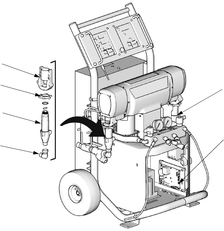
248669 Conversion Kit
312066Z 71
248669 Conversion Kit
Convert and phase E-XP2 to and E-30 with 15.3 kW of
heat by changing displacement pumps, bearings, and
changing the Motor Control DIP settings to that of an
E-30. For removal and installation of displacement
pumps and bearings, see Pump Removal (page 24)
and Pump Installation (page 26). For changing Motor
Control DIP settings, see Motor Control Board, page
34.
Ref. Part Description Qty.
65 118463 ELBOW, swivel; 3/4 npt(m) x 1 in.
npt(f)
2
303 245927 HOUSING, bearing 2
306A 246832 PUMP, displacement, component
A; see 309557
1
306B 245972 PUMP, displacement, component
B; see 309577
1
316 193394 NUT, retaining 2
TI10966a
303
316
306B
65
306A
24G881 Motor
Control Board
DIP Switch
(SW2) need to
be set for an
E-30. 1,2,3, ON -
4 OFF. See page
34.
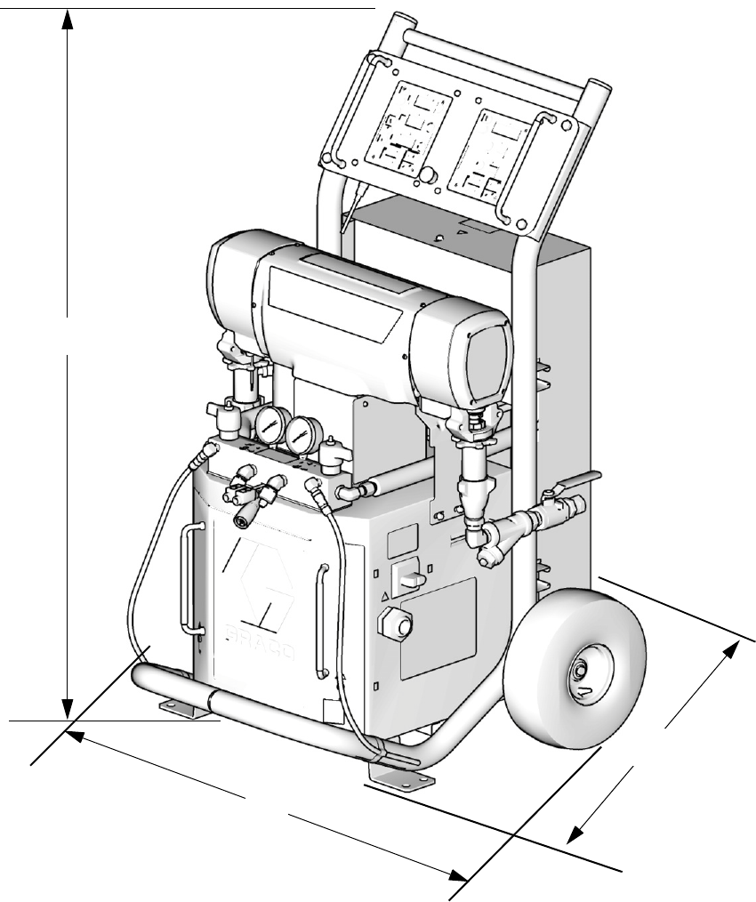
Dimensions
72 312066Z
Dimensions
Dimension in. (mm)
A 46.0 (1168)
B 31.0 (787)
C 33.0 (838)
TI10953a
B
A
C

Technical Data
312066Z 73
Technical Data
All other brand names or marks are used for identification purposes and are trademarks of their respective owners.
Category Data
Maximum Fluid Working Pressure Models E-20 and E-30: 2000 psi (14 MPa, 140 bar)
Model E-XP1: 2500 psi (17.2 MPa, 172 bar)
Model E-XP2: 3500 psi (24.1 MPa, 241 bar)
Maximum Fluid Temperature 190°F (88°C)
Maximum Output Model E-20: 20 lb/min (9 kg/min)
Model E-30: 30 lb/min (13.5 kg/min)
Model E-XP1: 1 gpm (3.8 liter/min)
Model E-XP2: 2 gpm (7.6 liter/min)
Output per Cycle (A and B) Model E-20 and E-XP1: 0.0104 gal. (0.0395 liter)
Model E-30: 0.0272 gal. (0.1034 liter)
Model E-XP2: 0.0203 gal. (.0771 liter)
Line Voltage Requirement Parts 259024, 259025, 259026, 259028, 259057: 195-264 Vac, 50/60 Hz
Parts 259029, 259030, 259031, 259032, 259059: 338-457 Vac, 50/60 Hz
Parts 259033, 259034, 259035, 259036, 259058: 195-264 Vac, 50/60 Hz
Amperage Requirement See Table 1, page 9.
Heater Power Model E-20: 6000 Watts
Model E-30 and E-XP1: 10200 Watts
Models E-XP2 and E-30 with 15.3kW of heat: 15300 Watts
Sound Power, per ISO 9614-2 Model E-20: 80 dB(A) at 2000 psi (14 MPa, 140 bar), 0.5 gpm (1.9 lpm)
Model E-30: 93.5 dB(A) at 1000 psi (7 MPa, 70 bar), 3.0 gpm (11.4 lpm)
Model E-XP1: 80 dB(A) at 2000 psi (14 MPa, 140 bar), 0.5 gpm (1.9 lpm)
Model E-XP2: 83.5 dB(A) at 3000 psi (21 MPa, 210 bar), 1.0 gpm (3.8 lpm)
Sound Pressure, 1 m from equipment Model E-20: 70.2 dB(A) at 2000 psi (14 MPa, 140 bar), 0.5 gpm (1.9 lpm)
Model E-30: 83.6 dB(A) at 1000 psi (7 MPa, 70 bar), 3.0 gpm (11.4 lpm)
Model E-XP1: 70.2 dB(A) at 2000 psi (14 MPa, 140 bar), 0.5 gpm (1.9 lpm)
Model E-XP2: 73.6 dB(A) at 3000 psi (21 MPa, 210 bar), 1.0 gpm (3.8 lpm)
Fluid Inlets 3/4 npt(f), with 3/4 npsm(f) union
Fluid Outlets Component A (ISO): -8 (1/2 in.) JIC, with -5 (5/16 in.) JIC adapter
Component B (RES): -10 (5/8 in.) JIC, with -6 (3/8 in.) JIC adapter
Fluid Circulation Ports 1/4 npsm(m), with plastic tubing; 250 psi (1.75 MPa, 17.5 bar) maximum
Weight Model E-20 and E-XP1: 342 lb (155 kg)
Model E-30: 400 lb (181kg)
Models E-XP2 and E-30 with 15.3kW of heat: 438 lb (198 kg)
Wetted Parts Aluminum, stainless steel, zinc plated, carbon steel, brass, carbide, chrome,
chemically resistant o-rings, PTFE, ultra-high molecular weight polyethylene
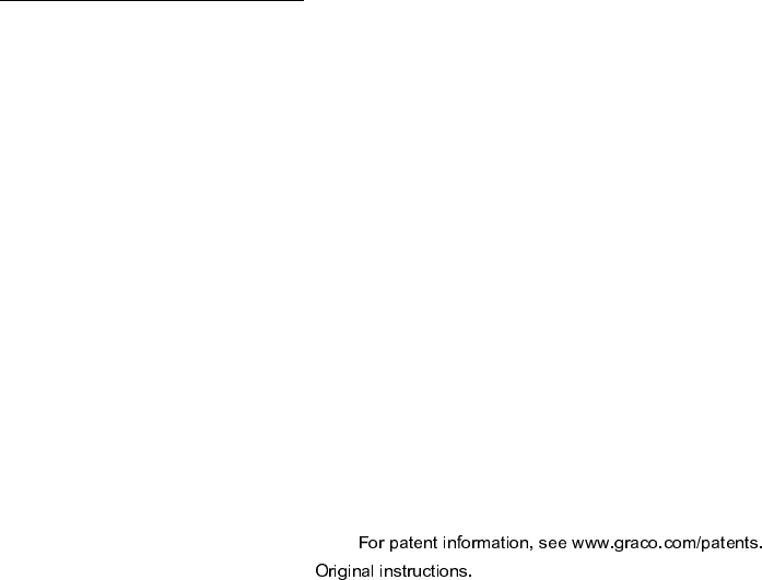
All written and visual data contained in this document reflects the latest product information available at the time of publication.
Graco reserves the right to make changes at any time without notice.
This manual contains English. MM 312066
Graco Headquarters: Minneapolis
International Offices: Belgium, China, Japan, Korea
GRACO INC. AND SUBSIDIARIES • P.O. BOX 1441 • MINNEAPOLIS MN 55440-1441 • USA
Copyright 2007, Graco Inc. All Graco manufacturing locations are registered to ISO 9001.
www.graco.com
Revision Z - January 2015
Graco Standard Warranty
Graco warrants all equipment referenced in this document which is manufactured by Graco and bearing its name to be free from defects in
material and workmanship on the date of sale to the original purchaser for use. With the exception of any special, extended, or limited warranty
published by Graco, Graco will, for a period of twelve months from the date of sale, repair or replace any part of the equipment determined by
Graco to be defective. This warranty applies only when the equipment is installed, operated and maintained in accordance with Graco’s written
recommendations.
This warranty does not cover, and Graco shall not be liable for general wear and tear, or any malfunction, damage or wear caused by faulty
installation, misapplication, abrasion, corrosion, inadequate or improper maintenance, negligence, accident, tampering, or substitution of
non-Graco component parts. Nor shall Graco be liable for malfunction, damage or wear caused by the incompatibility of Graco equipment with
structures, accessories, equipment or materials not supplied by Graco, or the improper design, manufacture, installation, operation or
maintenance of structures, accessories, equipment or materials not supplied by Graco.
This warranty is conditioned upon the prepaid return of the equipment claimed to be defective to an authorized Graco distributor for verification of
the claimed defect. If the claimed defect is verified, Graco will repair or replace free of charge any defective parts. The equipment will be returned
to the original purchaser transportation prepaid. If inspection of the equipment does not disclose any defect in material or workmanship, repairs
will be made at a reasonable charge, which charges may include the costs of parts, labor, and transportation.
THIS WARRANTY IS EXCLUSIVE, AND IS IN LIEU OF ANY OTHER WARRANTIES, EXPRESS OR IMPLIED, INCLUDING BUT NOT
LIMITED TO WARRANTY OF MERCHANTABILITY OR WARRANTY OF FITNESS FOR A PARTICULAR PURPOSE.
Graco’s sole obligation and buyer’s sole remedy for any breach of warranty shall be as set forth above. The buyer agrees that no other remedy
(including, but not limited to, incidental or consequential damages for lost profits, lost sales, injury to person or property, or any other incidental or
consequential loss) shall be available. Any action for breach of warranty must be brought within two (2) years of the date of sale.
GRACO MAKES NO WARRANTY, AND DISCLAIMS ALL IMPLIED WARRANTIES OF MERCHANTABILITY AND FITNESS FOR A
PARTICULAR PURPOSE, IN CONNECTION WITH ACCESSORIES, EQUIPMENT, MATERIALS OR COMPONENTS SOLD BUT NOT
MANUFACTURED BY GRACO. These items sold, but not manufactured by Graco (such as electric motors, switches, hose, etc.), are subject to
the warranty, if any, of their manufacturer. Graco will provide purchaser with reasonable assistance in making any claim for breach of these
warranties.
In no event will Graco be liable for indirect, incidental, special or consequential damages resulting from Graco supplying equipment hereunder, or
the furnishing, performance, or use of any products or other goods sold hereto, whether due to a breach of contract, breach of warranty, the
negligence of Graco, or otherwise.
FOR GRACO CANADA CUSTOMERS
The Parties acknowledge that they have required that the present document, as well as all documents, notices and legal proceedings entered into,
given or instituted pursuant hereto or relating directly or indirectly hereto, be drawn up in English. Les parties reconnaissent avoir convenu que la
rédaction du présente document sera en Anglais, ainsi que tous documents, avis et procédures judiciaires exécutés, donnés ou intentés, à la suite
de ou en rapport, directement ou indirectement, avec les procédures concernées.
Graco Information
For the latest information about Graco products, visit www.graco.com.
TO PLACE AN ORDER,
contact your Graco distributor or call to identify the nearest distributor.
Phone: 612-623-6921 or Toll Free: 1-800-328-0211, Fax: 612-378-3505
