Gree Electric Appliances of Zhuhai SAA1FB1F Remote Controller User Manual User Manul
Gree Electric Appliances, Inc. of Zhuhai Remote Controller User Manul
Contents
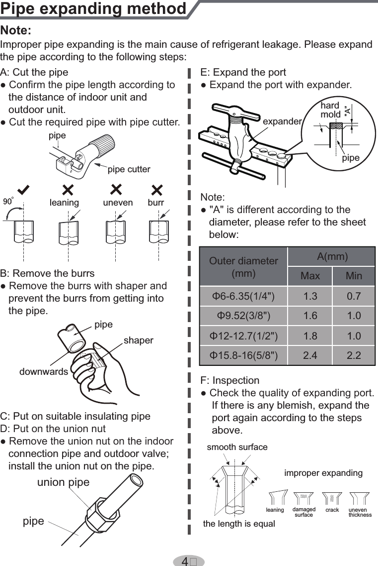
- 1. 140815007GZU_2ADAP-SAA1FB1F_User Manual-1_Rev1
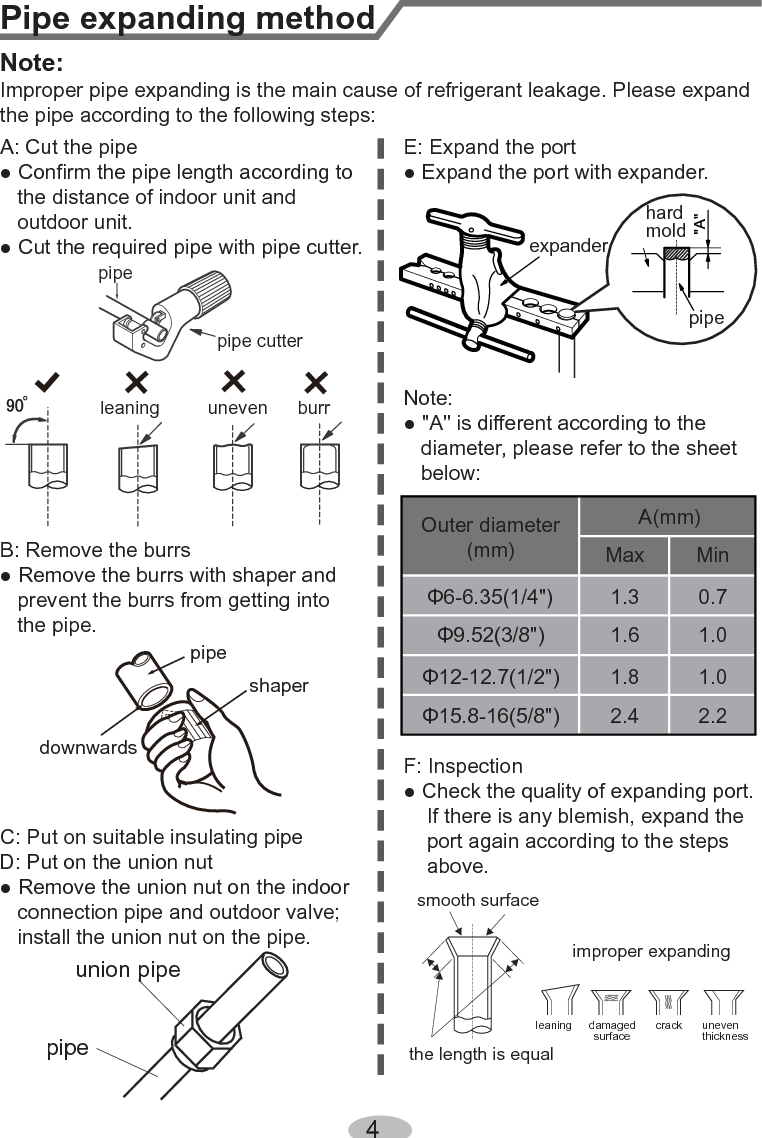
- 2. 140815007GZU_2ADAP-SAA1FB1F_User Manual-1_Rev2
140815007GZU_2ADAP-SAA1FB1F_User Manual-1_Rev2