Gree Electric Appliances of Zhuhai SAA1FB1F Remote Controller User Manual User Manul
Gree Electric Appliances, Inc. of Zhuhai Remote Controller User Manul
Contents
- 1. 140815007GZU_2ADAP-SAA1FB1F_User Manual-1_Rev1
- 2. 140815007GZU_2ADAP-SAA1FB1F_User Manual-1_Rev2
140815007GZU_2ADAP-SAA1FB1F_User Manual-1_Rev2
Operation of Smart Control (Smart Phone, Tablet PC)
9. Enter into the software interface again. Meanwhile, the short-distance remote
control setting for your air conditioner is finished.
22
How to reset the AC WiFi module:
Kindly remind:
1. The air conditioner WiFi function needs about 1 minute to start up.
2. The air conditioner has memory function.
3. Those models have no long-distance control.
Turn unit off with the remote controller and disconnect the power of AC. Then
re-connect the power. 1 minute later, press “WiFi” and “Mode” buttons simultaneously.
If the AC gives out a beep sound, it means the WiFi module is successfully reset.
Attention: Operation of the buttons is only effective in 2 minutes.
Analysis on Common Network Setting Failure:
1. If short-distance control fails, please check the following items one by one!
·Make sure AC is power connected;
·Make sure AC’s WiFi function is turned on as normal;
·Make sure your phone’s WiFi selects the corresponding AC;
·Reset with the remote controller and then start setting again from step 3.
23
Operation of Smart Control (Smart Phone, Tablet PC)
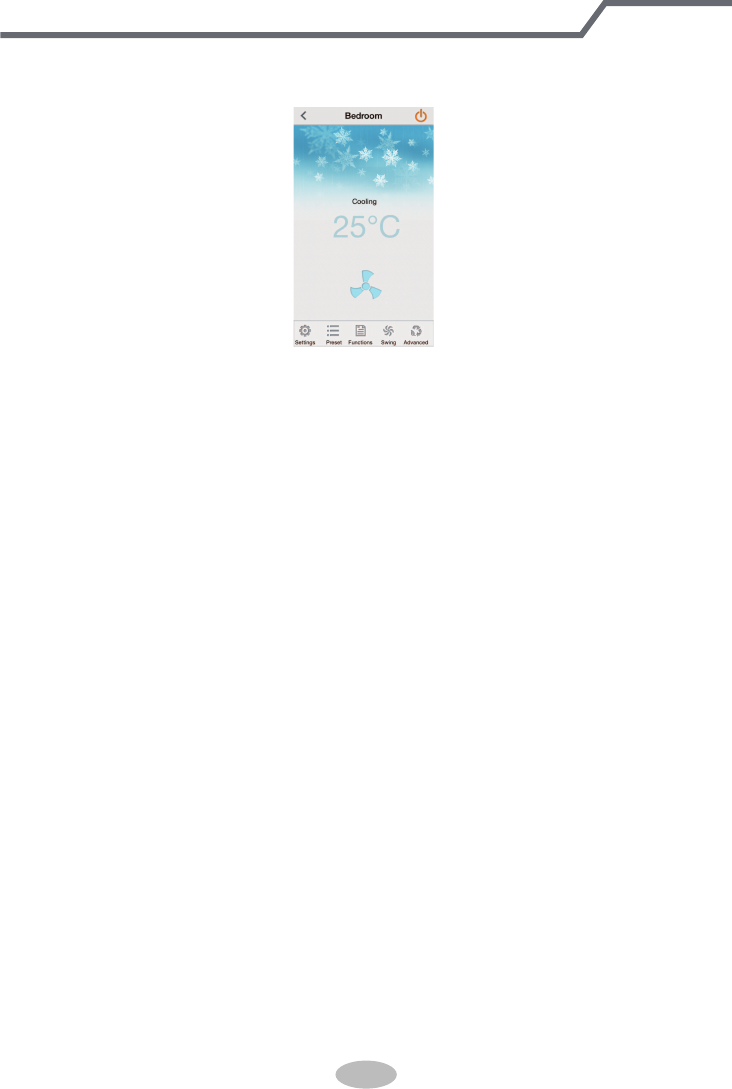
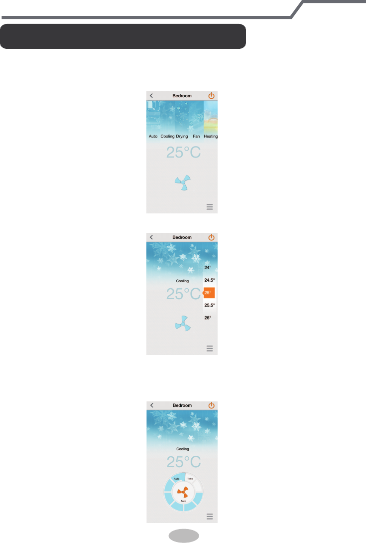
1. Mode: It used for setting operation mode for air conditioner. You can select “Auto”,
“Cooling”, “Drying”, “Fan” or “Heating” according to your requirement. Please refer to
the part of remote controller for the detailed operation.
3.
Fan Speed: It used for setting fan speed. Under cooling or heating mode, if the
noise-customized function is turned on, adjust the fan speed and then the noise-
-customized function will be turned off automatically. Please refer to the part of remote
controller for detailed operation.
2. Temperature: It used for setting temperature. Set the indoor temperature according to
your requirement.
Function Introduction on Main Interface
24
Operation of Smart Control (Smart Phone, Tablet PC)
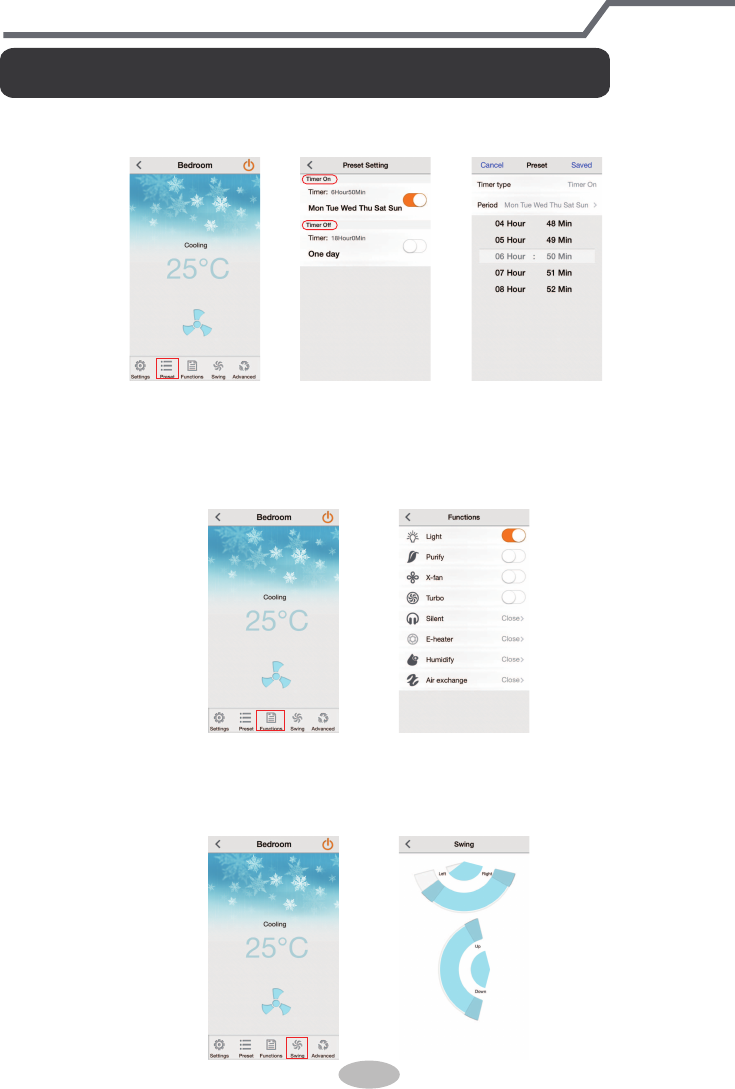
1. Preset: It’s with Timer On and Timer Off function. User can set Timer On and Timer
Off according to actual individual requirement.
2.
Functions: After entering setting interface, you can turn on or turn off Light, Purify,
X-fan and Turbo functions and set Silent, Humidify, Air exchange and other modes.
Please refer to the part of remote controller for the function instruction. Among that,
Purify, Humidify, Air exchange functions can be set through equipping with special
air purifier, humidifier. E-heater is not available for this unit.
Key Functions Instruction of Application Software
3.
Swing: During up&down swing and left&right swing, it’s the fixed angle swing
when those two sliding blocks are combined together and full swing when they are
separated. When setting up&down swing, the program will turn off regional swing
function. However, no influence for regional swing when setting left&right swing.
25
Operation of Smart Control (Smart Phone, Tablet PC)
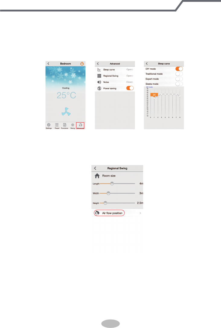
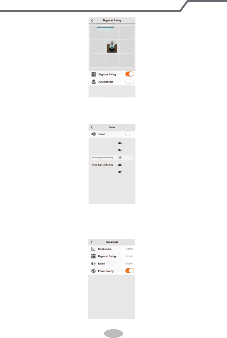
4. Advanced: After entering advanced interface, you can set Sleep curve, Regional
Swing, Noise and Power saving.
●
Regional Swing: After entering Regional Swing, user can set it according to the
room size. Press “Air flow position” button and the user can adjust the fan-blowing
area through moving the icon of air conditioner left and right according to the
actual installation position of the unit.
User can move the person icon among nine pane areas according to requirement
to adjust the fan-blow area. The Regional Swing function can be turned off through
up&down swing. The up&down swing in the Regional Swing is only valid under
cooling and heating modes. The left&right swing area has relationship with the
position of air conditioner set by mobile phone. The left&right swing position may
be asymmetry, which is the normal phenomenon.
“Avoid people” function can be turned on or turned off according to user’s
personal experience. There may be deviation because of the installation position
of air conditioner and the setting of parameters, which is the normal phenomenon.
● Sleep curve: Sleep curve includes DIY mode, Traditional mode, Expert mode and
Siesta mode. Under DIY mode, you can set temperature and time. Under auto
mode and fan mode, sleep curve function can’t be turned on. Only Traditional
mode can be selected under dry mode.
26
Operation of Smart Control (Smart Phone, Tablet PC)
●
Power saving: After energy saving navigation mode is turned on, the air
conditioner will detect indoor temperature and outdoor temperature automatically.
Meanwhile, the air conditioner will adjust frequency, fan speed and set tempera-
ture automatically according to the load status for saving energy.
●
Noise: The noise-customized function for indoor unit can be adjusted according to the
actual individual requirement. The detailed adjustment range is different for different
models, which is decided by indoor unit.
27
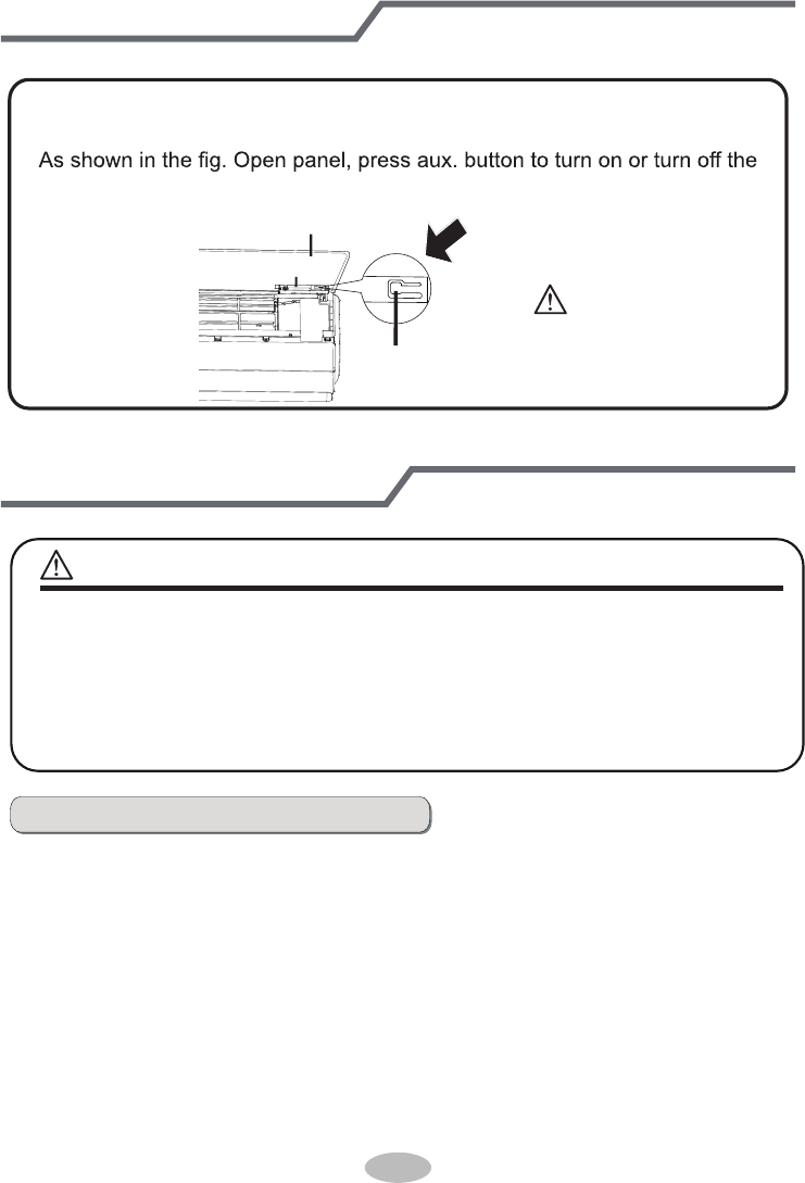
Emergency operation
If remote controller is lost or damaged, please use auxiliary button to turn
on or turn off the air conditioner. The operation in details are as below:
air conditioner. When the air conditioner is turned on, it will operate under
auto mode.
aux. button
panel
Display panel
Clean and maintenance
■ Turn off the air conditioner and disconnect the power before cleaning the air
conditioner to avoid electric shock.
■ Do not wash the air conditioner with water to avoid electric shock.
■ Do not use volatile liquid to clean the air conditioner.
Clean surface of indoor unit
When the surface of indoor unit is dirty, it is recommended to use a soft dry cloth
or wet cloth to wipe it.
NOTICE:
● Do not remove the panel when cleaning it.
WARNING
WARNING:
Use insulated object to
press the auto button
Clean and maintenance
28
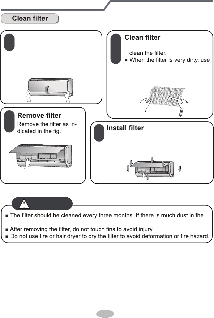
operation environment, clean frequency can be increased.
WARNING
1
2
3
4
Open panel
● Use dust catcher or water to Open the panel into a certain
angle(less than 60°, do not open
the panel too forcibly) along the
arrow direction from the two
sides of panel.
the water (below 45ć) to clean
it, and then put it in a shady
and cool place to dry.
Install the filter and then close the panel
cover tightly.(Press the arrow (1) position
to check whether it buckled tightly. )
Clean and maintenance
Notice for recovery
1. Many packing materials are recyclable materials.
Please dispose them in appropriate recycling unit.
2. If you want to dispose the air conditioner, please contact local dealer or
consultant service center for the correct disposal method.
29
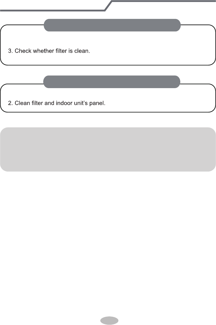
NOTICE: Checking after use-season
1. Check whether air inlets and air outlets are blocked.
2. Check whether circuit break, plug and socket are in good condition.
4. Check whether drainage pipe is damaged.
1. Disconnect power supply.
NOTICE: Checking before use-season
Malfunction analysis
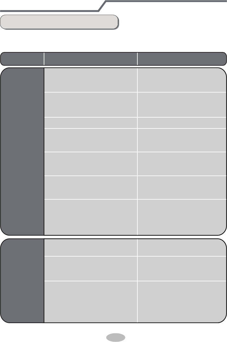
General phenomenon analysis
Please check below items before asking for maintenance. If the malfunction still
can’t be eliminated, please contact local dealer or qualified professionals.
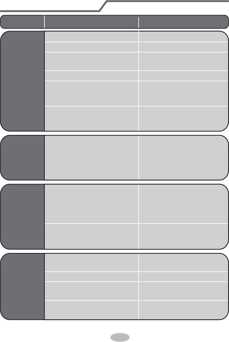
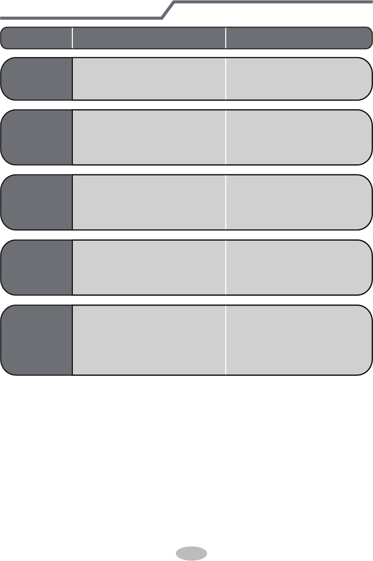
Phenomenon Check items Solution
Indoor unit
can’t receive
remote
controller’s
signal or
remote
controller
has no
action.
● Whether it's interfered severely
(such as static electricity,stable
voltage)?
● Whether remote controller is
within the signal receiving
range?
● Whether there are obstacles?
● Whether remote controller is
pointing at the receiving
window?
● Is sensitivity of remote contro-
ller low; fuzzy display and no
display?
● No display when operating
remote controller?
● Fluorescent lamp in room?
● Pull out the plug. Reinsert
the plug after about 3min, and
then turn on the unit again.
● Signal receiving range is 8m.
● Remove obstacles.
●
Select proper angle and point
the remote controller at the re-
ceiving window on indoor unit.
● Check the batteries. If the
power of batteries is too low,
please replace them.
● Take the remote controller
close to indoor unit.
● Turn off the fluoresent lamp
and then try it again.
● Check whether remote cont-
roller appears to be damaged.
If yes, replace it.
No air
emitted
from
indoor
unit
● Air inlet or air outlet of indoor
unit is blocked?
● Eliminate obstacles.
● Under heating mode, indoor
temperature is reached to set
temperature?
● After reaching to set temper-
ature, indoor unit will stop bl-
owing out air.
● Heating mode is turned on just
now?
● In order to prevent blowing
out cold air, indoor unit will be
started after delaying for sev-
eral minutes, which is a nor-
mal phenomenon.
30
Malfunction analysis
● Power failure?
● Is plug loose?
● Air switch trips off or fuse is
burnt out?
● Wiring has malfunction?
● Unit has restarted immediately
after stopping operation?
● Whether the function setting
for remote controller is
correct?
● Reset the function.
● Wait for 3min, and then turn
on the unit again.
● Ask professional to replace it.
● Ask professional to replace
air switch or fuse.
● Reinsert the plug.
● Wait until power recovery.
Air condit-
ioner can’t
operate
Mist is em-
itted from
indoor unit’s
air outlet
● Indoor temperature and hum-
idity is high?
● Because indoor air is cooled
rapidly. After a while, indoor
temperature and humidity will
be decrease and mist will
disappear.
Phenomenon Check items Solution
Set temper-
ature can’t
be adjusted
● Unit is operating under auto
mode?
● Temperature can’t be adju-
sted under auto mode.
Please switch the operation
mode if you need to adjust
temperature.
● Your required temperature
exceeds the set temperature
range?
● Set temperature range:
16ć~30ć.
Cooling
(heating)
effect is
not good.
● Voltage is too low? ● Wait until the voltage
resumes normal.
● Filter is dirty? ● Clean the filter.
● Set temperature is in proper
range?
● Adjust temperature to proper
range.
● Door and window are open? ● Close door and window.
31
Phenomenon Check items Solution
Odours are
emitted
● Whether there’s odour source,
such as furniture and cigarette,
etc.
● Eliminate the odour source.
● Clean the filter.
Air conditioner
operates nor-
mally suddenly
● Whether there’s interference,
such as thunder, wireless
devices, etc.
● Disconnect power, put back
power, and then turn on the
unit again.
Outdoor
unit has
vapor
● Heating mode is turned on?
● During defrosting under he-
ating mode, it may generate
vapor, which is a normal
phenomenon.
“Water
flowing”
noise
● Air conditioner is turned on or
turned off just now?
● The noise is the sound of
refrigerant flowing inside
the unit, which is a normal
phenomenon.
Cracking
noise
● Air conditioner is turned on or
turned off just now?
● This is the sound of friction
caused by expansion and/or
contraction of panel or other
parts due to the change of
temperature.
Malfunction analysis
32
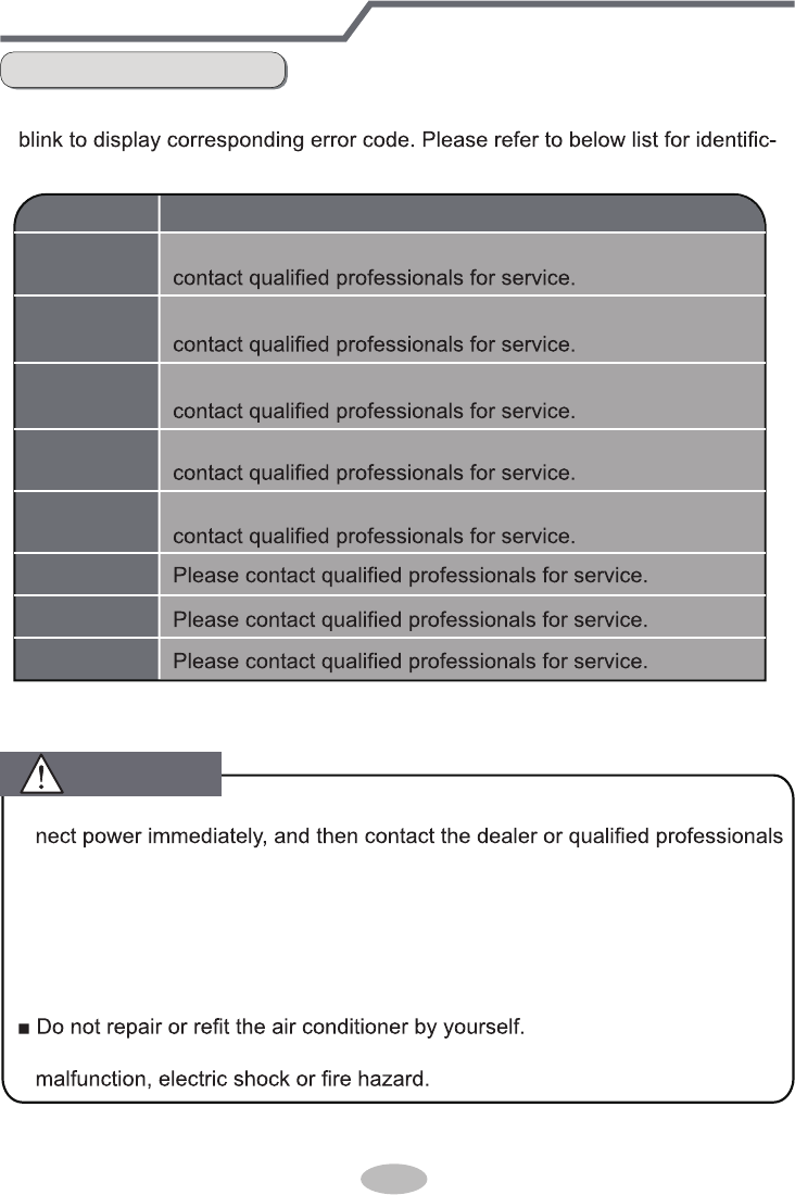
Note: If there're other error codes, please contact qualified professionals for
service.
WARNING
Error code
E5
E8
E6
U8
H6
C5
F1
F2
Troubleshooting
It can be eliminated after restarting the unit. If not , please
It can be eliminated after restarting the unit. If not , please
It can be eliminated after restarting the unit. If not,please
It can be eliminated after restarting the unit. If not,please
It can be eliminated after restarting the unit. If not,please
■ When below phenomenon occurs, please turn off air conditioner and discon-
for service.
● Power cord is overheating or damaged.
● There’s abnormal sound during operation.
● Air switch trips off frequently.
● Air conditioner gives off burning smell.
● Indoor unit is leaking.
■ If the air conditioner operates under abnormal conditions, it may cause
Error Code
● When air conditioner status is abnormal, temperature indictor on indoor unit will
ation of error code.
Malfunction analysis
33
34
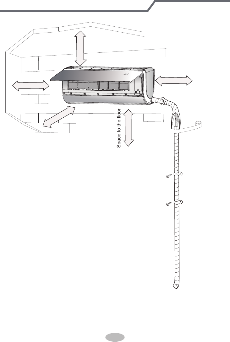
Installation dimension diagram
At least 250cm
At least 15cm
At least 300cm
Space to the ceiling
Space to the obstruction
At least 15cm
At least 15cm
Space to the wall
Space to the wall
35
1. There should be no obstruction near air
inlet and air outlet.
2. Select a location where the condensat-
ion water can be dispersed easily and
won't affect other people.
3. Select a location which is convenient to
connect the outdoor unit and near the
power socket.
4. Select a location which is out of reach
for children.
5.
The location should be able to withstand
the weight of indoor unit and won't incr-
ease noise and vibration.
6.
The appliance must be installed 2.5m
7. Don't install the indoor unit right above
the electric appliance.
8. Please try your best to keep way from
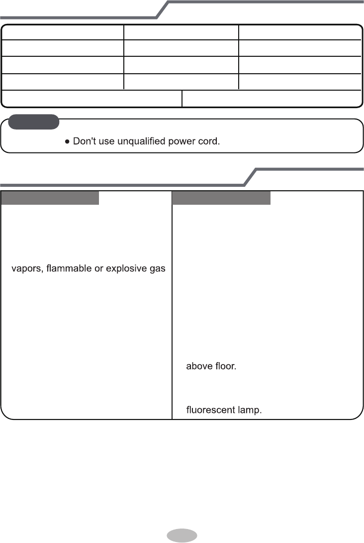
Tools for installation
Selection of installation location
1 Level meter 2 Screw driver 3 Impact drill
4 Drill head 5 Pipe expander 6 Torque wrench
7 Open-end wrench 8 Pipe cutter 9 Leakage detector
10 Vacuum pump 11 Pressure meter 12 Universal meter
13 Inner hexagon spanner 14 Measuring tape
Note: ● Please contact the local agent for installation.
Basic requirement Indoor unit
Installing the unit in the following pla-
ces maycause malfunction. If it is un-
avoidable, please consult the local
dealer:
1.The place with strong heat sources,
,
or volatile objects spread in the air.
2.The place with high-frequency
devices (such as welding machine,
medical equipment).
3.The place near coast area.
4.
The place with oil or fumes in the air.
5.The place with sulfureted gas.
6.Other places with special circums-
tances.
7.The appliance shall not be installed
in the laundry.
36
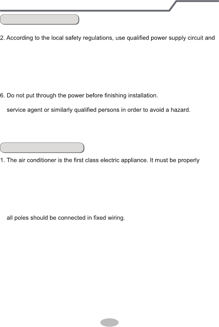
Requirements for electric connection
Safety precaution
Grounding requirement
1. Must follow the electric safety regulations when installing the unit.
air switch.
3. Make sure the power supply matches with the requirement of air conditioner.
Unstable power supply or incorrect wiring or malfunction. Please install proper
power supply cables before using the air conditioner.
4. Properly connect the live wire, neutral wire and grounding wire of power socket.
5. Be sure to cut off the power supply before proceeding any work related to
electricity and safety.
7. If the supply cord is damaged, it must be replaced by the manufacturer, its
8. The temperature of refrigerant circuit will be high, please keep the interconnec-
tion cable away from the copper tube.
9. The appliance shall be installed in accordance with national wiring regulations.
grounding with specialized grounding device by a professional. Please make
sure it is always grounded effectively, otherwise it may cause electric shock.
2. The yellow-green wire in air conditioner is grounding wire, which can't be used
for other purposes.
3. The grounding resistance should comply with national electric safety regulations.
4. The appliance must be positioned so that the plug is accessible.
5. An all-pole disconnection switch having a contact separation of at least 3mm in
For models with a power plug, make
sure the plug is within reach after installation.
37
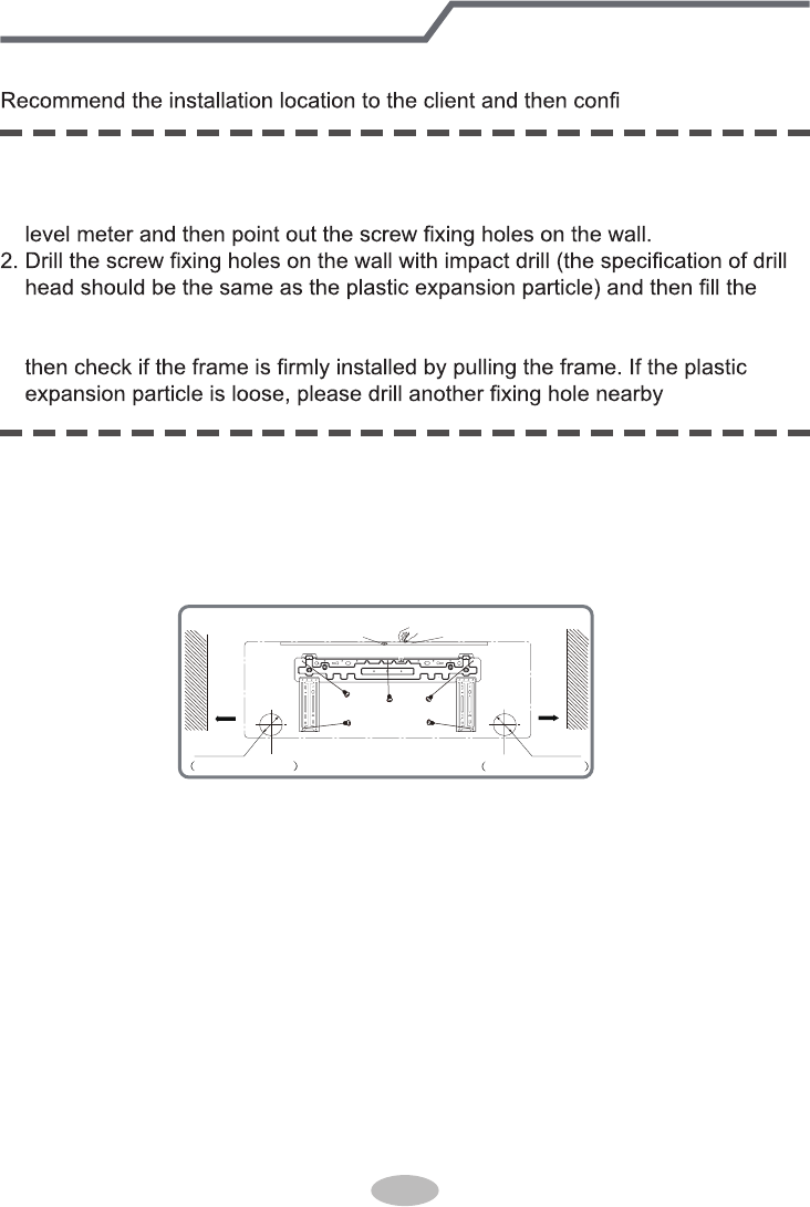
Installation of indoor unit
Step one: choosing installation location
Step two: install wall-mounting frame
rm it with the client.
1. Hang the wall-mounting frame on the wall; adjust it in horizontal position with the
plastic expansion particles in the holes.
3. Fix the wall-mounting frame on the wall with tapping screws (ST4.2X25TA) and
.
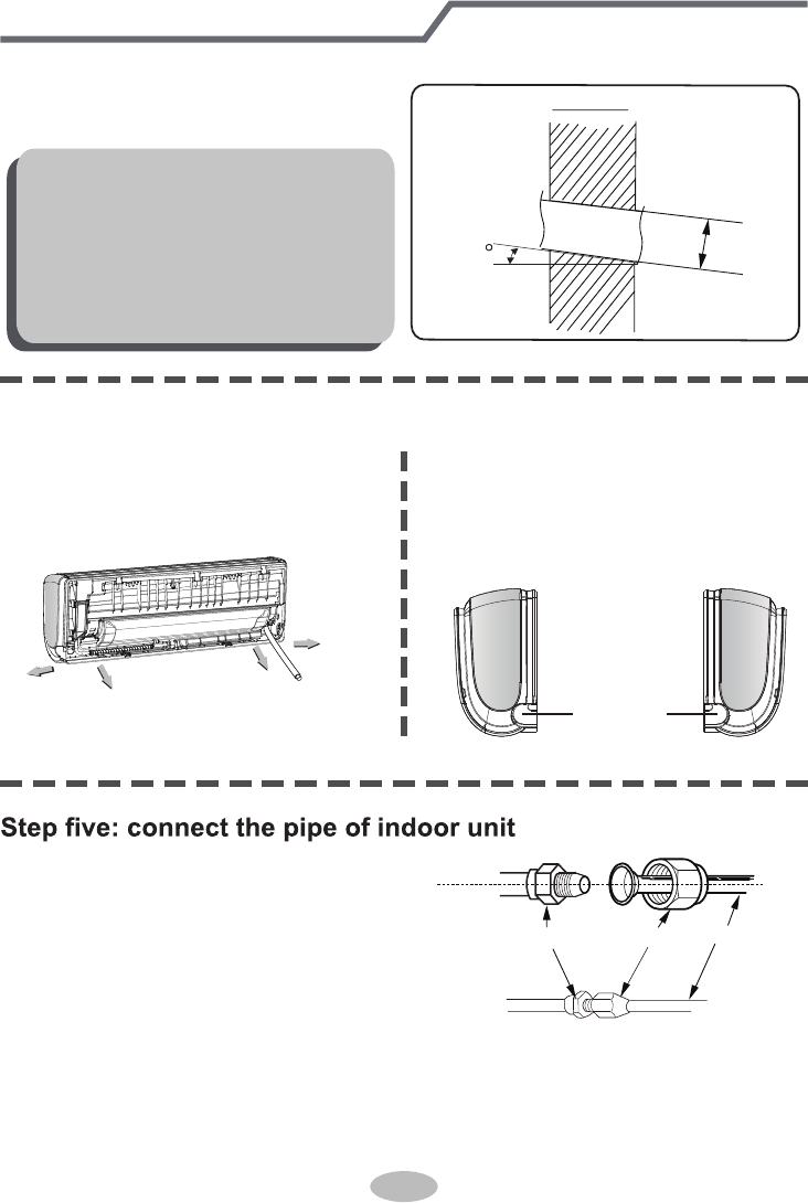
1. Choose the position of piping hole according to the direction of outlet pipe. The
position of piping hole should be a little lower than the wall-mounted frame,
shown as below.
Step three: open piping hole
2. Open a piping hole with the diameter of Φ55 or Φ70 on the selected outlet pipe
position.In order to drain smoothly, slant the piping hole on the wall slightly
downward to the outdoor side with the gradient of 5-10°.
Left
Wall
Φ55/70mm
Right
Mark in the middle of it Level meter
Rear piping hole
Wall
Space
to the
wall
above
150mm
Space
to the
wall
above
150mm
Φ55/70mm
Rear piping hole
38
1. Aim the pipe joint at the corresponding
bellmouth.
2. Pretightening the union nut with hand.
3. Adjust the torque force by referring to the following sheet. Place the open-end
wrench on the pipe joint and place the torque wrench on the union nut. Tighten
the union nut with torque wrench.
2. When select leading out the pipe
from left or right, please cut off the
corresponding hole on the bottom
case.
cut off
the hole
left right
1. The pipe can be led out in the
direction of right, rear right, left or
rear left.
left
rear left
right
rear right
Step four: outlet pipe
Installation of indoor unit
union nutpipe joint pipe
Note:
● Pay attention to dust prevention and
take relevant safety measures when
opening the hole.
● The plastic expansion particles are
not provided and should be bought
locally.
Indoor
5-10
outdoor
Φ55 /
Φ70
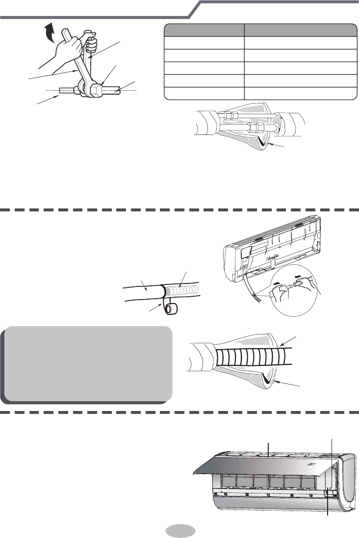
4. Wrap the indoor pipe and joint of con-
nection pipe with insulating pipe, and
then wrap it with tape.
Step six: install drain hose
Installation of indoor unit
torque wrench
open-end
wrench
indoor pipe
pipe
union nut
Hex nut diameter Tightening torque (N.m)
Φ 6
Φ 9.52
Φ 12
Φ 16
Φ 19
30~40
45~55
60~65
70~75
15~20
insulating pipe
1. Connect the drain hose to the outlet pipe of
indoor unit.
2. Bind the joint with tape.
outlet
pipe
drain hose
drain hose
tape
outlet pipe
drain hose
insulating pipe
Note:
● Add insulating pipe in the indoor
drain hose in order to prevent
condensation.
● The plastic expansion particles are
not provided.
1. Open the panel, remove the screw
on the wiring cover and then take
down the cover.
wiring cover
screw
pane
Step seven: connect wire of indoor unit
39
5. If a 18k indoor unit is to be connected with Free Match outdoor unit, a transitional
pipe joint (provided) should be added at the pipe joint of indoor unit evaporator assy
as the pipe joint of evaporator assy adopts pipe diameter of Φ16. Please refer to step
1-4 during installation.
40
Installation of indoor unit
Note:
● All wires of indoor unit and outdoor uni
If the length of power connection wire is insufficient, please contact the supplier
For the air conditioner with plug, the plug should be reachable after finishing
t should be connected by a professional.
installation.
● For the air conditioner without plug, an air switch must be installed in the line.
The air switch should be all-pole parting and the contact parting distance should
be more than 3mm.
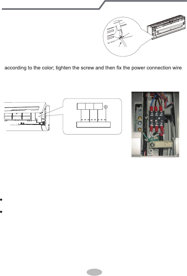
2. Make the power connection wire go
through the cable-cross hole at the back
of indoor unit and then pull it out from
the front side.
for a new one. Avoid extending the wire by yourself.
power connection
wire
cable-cross
hole
L2’
S
L1’
Outdoor unit connection
green
green)
red
black
(yellow-
(brown)
white
(blue)
3. Remove the wire clip; connect the power connection wire to the wiring terminal
with wire clip.After finishing wiring , clamp the grounding wire (yellow-green wire)
4.Put wiring cover back and then tighten the screw
5.Close the panel.
into the wire-crossing groove as shown in the following figure, in order to avoid
pressing the wire when closing the electric box cover.
Installation of indoor unit
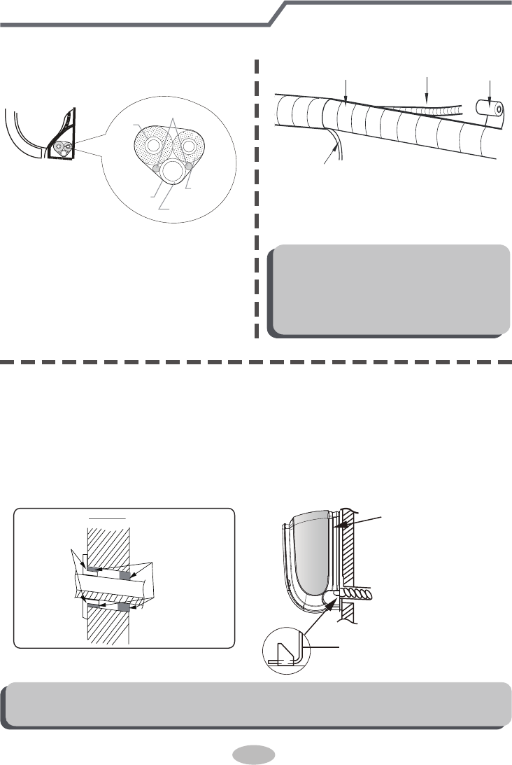
Step eight: bind up pipe
1. Bind up the connection pipe, power
cord and drain hose with the band.
indoor unit gas
pipe
indoor and
outdoor power cord
liquid pipe
drain hose
band
2. Reserve a certain length of drain
hose and power cord for installation
when binding them. When binding to
a certain degree, separate the indoor
power and then separate the drain
hose.
3. Bind them evenly.
4. The liquid pipe and gas pipe should
be bound separately at the end.
Note:
● The power cord and control wire
can't be crossed or winding.
● The drain hose should be bound
at the bottom.
drain hose band
connection pipe
indoor power cord
Step nine: hang the indoor unit
1. Put the bound pipes in the wall pipe and then make them pass through the wall
hole.
2. Hang the indoor unit on the wall-mounting frame.
3. Stuff the gap between pipes and wall hole with sealing gum.
4. Fix the wall pipe.
upper hook
lower hook of
5.Check if the indoor unit is installed firmly and closed to the wall.
wall-mounting frame
Note:
● Do not bend the drain hose too excessively in order to prevent blocking.
indoor outdoor
wall pipe sealing gum
41
Leakage detection
6. Tighten the screw caps of valves and refrigerant charging vent.
7. Reinstall the handle.
1. With leakage detector:
Check if there is leakage with leakage detector.
2. With soap water:
If leakage detector is not available, please use soap water for leakage detection.
Apply soap water at the suspected position and keep the soap water for more
than 3min. If there are air bubbles coming out of this position, there's a leakage.
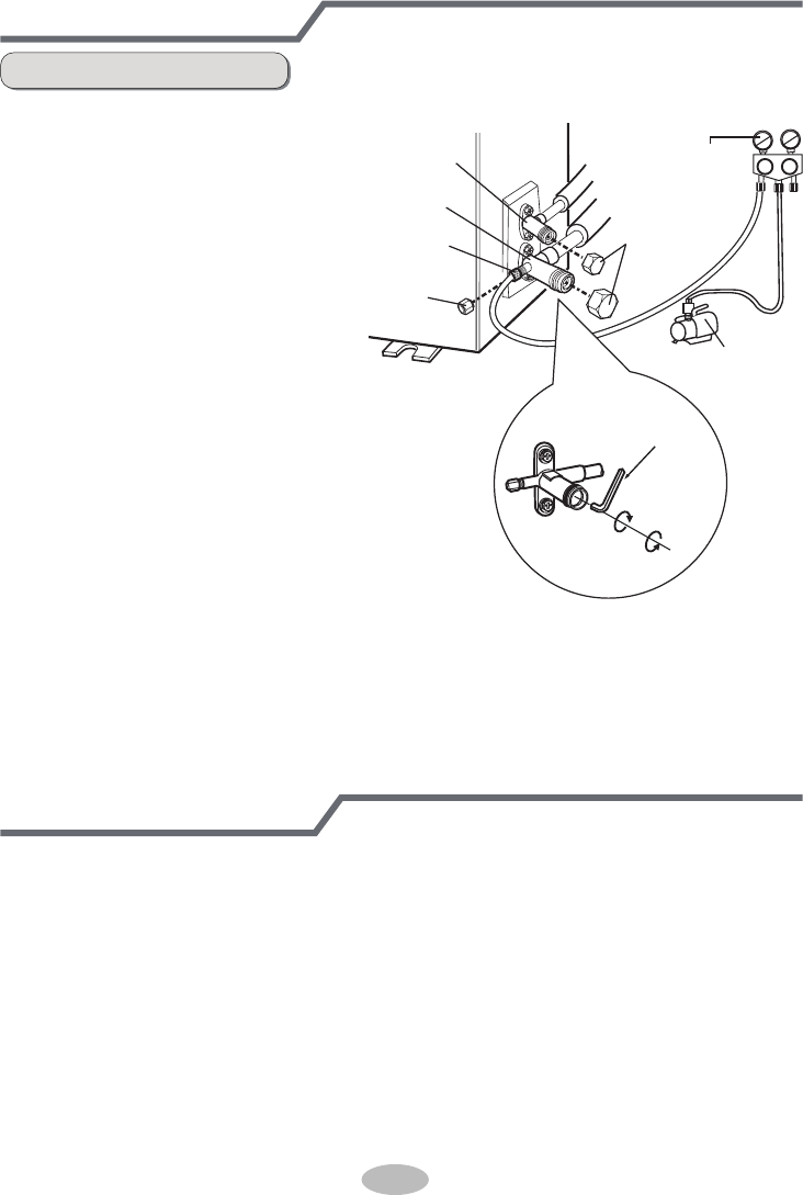
Vacuum pumping
1. Remove the valve caps on
the liquid valve and gas
valve and the nut of refri-
gerant charging vent.
2. Connect the charging hose
of piezometer to the refri-
gerant charging vent of gas
valve and then connect the
other charging hose to the
vacuum pump.
3. Open the piezometer com-
pletely and operate for
10-15min to check if the
pressure of piezometer re-
mains in -0.1MPa.
4. Close the vacuum pump
and maintain this status for
1-2min to check if the pres-
sure of piezometer remains
in -0.1MPa. If the pressure decreases, there may be leakage.
5. Remove the piezometer, open the valve core of liquid valve and gas valve
completely with inner hexagon spanner.
Use vacuum pump
liquid valve
gas valve
refrigerant charging
vent
nut of refrigerant
charging vent
vacuum pump
piezometer
valve cap
Lo Hi
inner hexagon
spanner
open
close
42
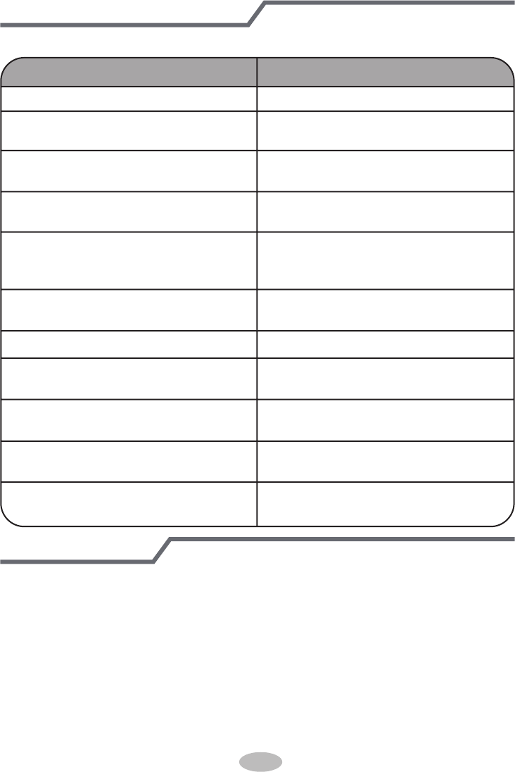
Check after installation
Test operation
● Check according to the following requirement after finishing installation.
Items to be checked Possible malfunction
Has the unit been installed firmly? The unit may drop, shake or emit noise.
Have you done the refrigerant leakage
test?
It may cause insufficient cooling
(heating) capacity.
Is heat insulation of pipeline sufficient? It may cause condensation and water
dripping.
Is water drained well? It may cause condensation and water
dripping.
Is the voltage of power supply accord-
ing to the voltage marked on the
nameplate?
It may cause malfunction or damaging
the parts.
Is electric wiring and pipeline installed
correctly?
It may cause malfunction or damaging
the parts.
Is the unit grounded securely? It may cause electric leakage.
Does the power cord follow the speci-
fication?
It may cause malfunction or damaging
the parts.
Is there any obstruction in the air inlet
and outlet?
It may cause insufficient cooling
(heating) capacity.
The dust and sundries caused during
installation are removed?
It may cause malfunction or damaging
the parts.
The gas valve and liquid valve of
connection pipe are open completely?
It may cause insufficient cooling
(heating) capacity.
1. Preparation of test operation
● The client approves the air conditioner.
● Specify the important notes for air conditioner to the client.
2. Method of test operation
● Put through the power, press ON/OFF button on the remote controller to start
operation.
● Press MODE button to select AUTO, COOL, DRY, FAN and HEAT to check
whether the operation is normal or not.
● If the ambient temperature is lower than 16ć, the air conditioner can’t
start cooling.
43
44
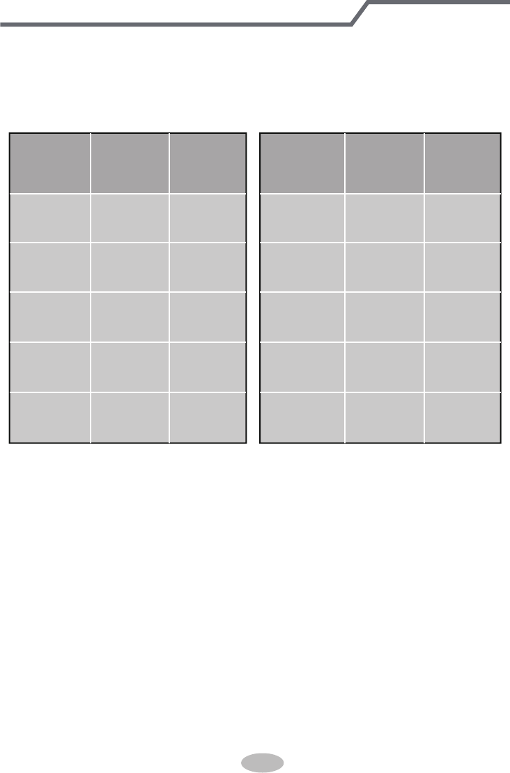
1. Standard length of connection pipe
● 5m, 7.5m, 8m.
4. The additional refrigerant oil and refrigerant charging required after prolonging
connection pipe
● After the length of connection pipe is prolonged for 10m at the basis of
standard length, you should add 5ml of refrigerant oil for each additional 5m
of connection pipe.
● The calculation method of additional refrigerant charging amount (on the basis
of liquid pipe):
● Basing on the length of standard pipe, add refrigerant according to the
requirement as shown in the table. The additional refrigerant charging amount
per meter is different according to the diameter of liquid pipe. See the
following sheet.
Additional refrigerant charging amount=prolonged length of liquid pipe×
additional refrigerant charging amount per meter
Cooling
capacity
Cooling
capacity
5000Btu/h
(1465W)
24000Btu/h
(7032W)
7000Btu/h
(2051W)
28000Btu/h
(8204W)
9000Btu/h
(2637W)
36000Btu/h
(10548W)
12000Btu/h
(3516W)
42000Btu/h
(12306W)
18000Btu/h
(5274W)
48000Btu/h
(14064W)
Max height
difference
Max height
difference
Max length
of connec-
tion pipe
Max length
of connec-
tion pipe
15 255 10
15 305 10
15 305 20
20 3010 20
25 3010 20
2.Min. length of connection pipe is 3m.
3.Max. length of connection pipe and max. high difference.
Configuration of connection pipe
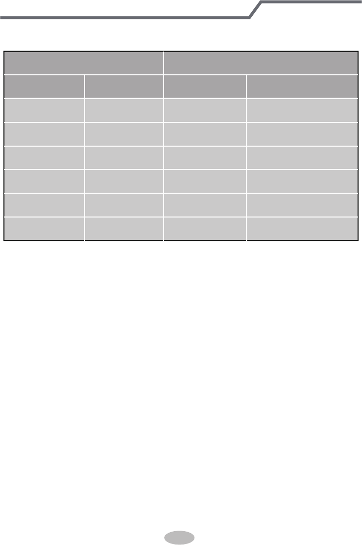
Additional refrigerant charging amount for R22, R407C, R410A and R134a
Diameter of connection pipe
Liquid pipe(mm) Gas pipe(mm)
Φ6
Φ6 or Φ9.52
Φ12
Φ16
Φ19
Φ22.2
Φ9.52 or Φ12
Φ16 or Φ19
Φ19 or Φ22.2
Φ25.4 or Φ31.8
_
_
Cooling only(g/m) Cooling and heating(g/m)
15
15
30
60
250 250
350350
120
120
50
20
Outdoor unit throttle
&RQ¿JXUDWLRQRIFRQQHFWLRQSLSH
45
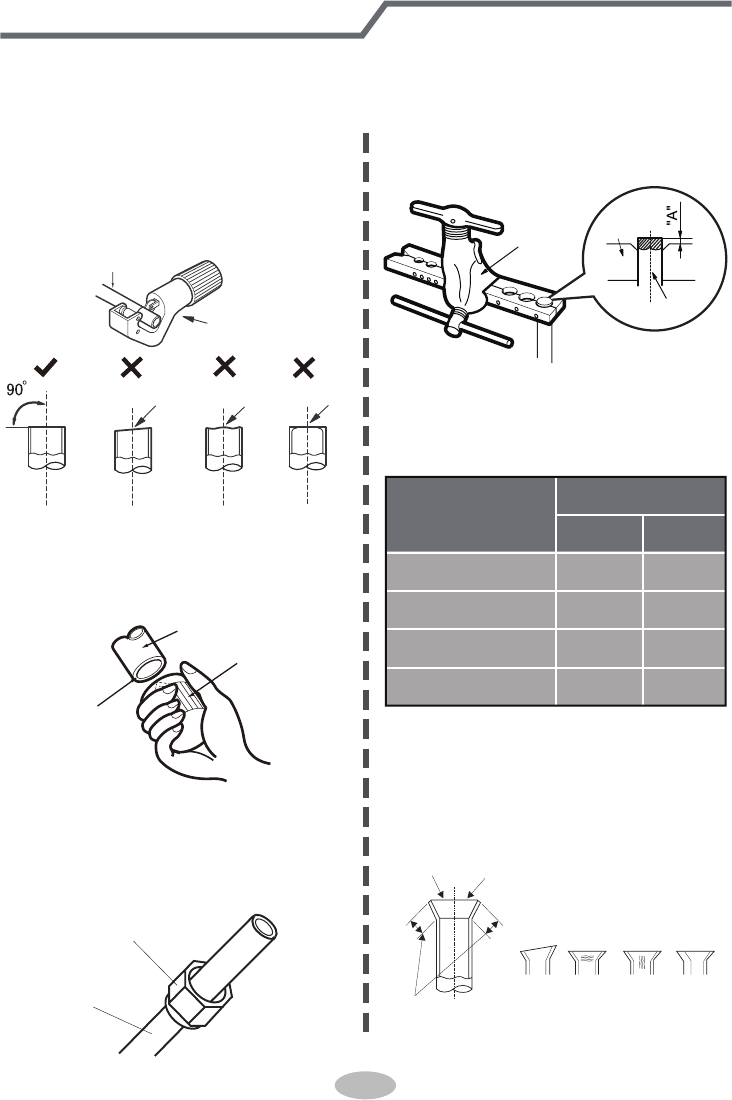
Pipe expanding method
Note:
Improper pipe expanding is the main cause of refrigerant leakage. Please expand
the pipe according to the following steps:
A: Cut the pipe
● Confirm the pipe length according to
the distance of indoor unit and
outdoor unit.
● Cut the required pipe with pipe cutter.
pipe
pipe cutter
leaning uneven burr
B: Remove the burrs
● Remove the burrs with shaper and
prevent the burrs from getting into
the pipe.
downwards
pipe
shaper
C: Put on suitable insulating pipe
D: Put on the union nut
● Remove the union nut on the indoor
connection pipe and outdoor valve;
install the union nut on the pipe.
union pipe
pipe
E: Expand the port
● Expand the port with expander.
Note:
● "A" is different according to the
diameter, please refer to the sheet
below:
expander
hard
mold
pipe
F: Inspection
● Check the quality of expanding port.
If there is any blemish, expand the
port again according to the steps
above.
the length is equal
improper expanding
leaning damaged
surface
crack uneven
thickness
smooth surface
Outer diameter
(mm)
A(mm)
Max Min
Φ6-6.35(1/4")
Φ9.52(3/8")
Φ12-12.7(1/2")
Φ15.8-16(5/8")
1.3 0.7
1.6 1.0
1.8 1.0
2.4 2.2
46

Add: West Jinji Rd, Qianshan, Zhuhai, Guangdong, China, 519070
Tel: (+86-756) 8522218 Fax: (+86-756) 8669426
E-mail: gree@gree.com.cn www.gree.com
GREE ELECTRIC APPLIANCES, INC. OF ZHUHAI
66160000125