Guangzhou Chiyuan Electronic N-4Q Radio Control System User Manual
Guangzhou Chiyuan Electronic Co., Ltd. Radio Control System Users Manual
Contents
- 1. Users Manual
- 2. User Manual
Users Manual
T P C A R EOT P C A R EO
Guangzhou Chiyuan Electronic Co., Ltd
Add: 2/F., No. 1 Bldg., Boyi Industrial Garden, 4th Gongye Rd.
Zhicun, Dashi Street, Panyu Dis., Guangzhou, China
P.C.:511430
Tel: +86-20-34796226;34797226
Fax: +86-20-34796116
Website: www.chiyuan.net
E-mail: gzchiyuan@126.com
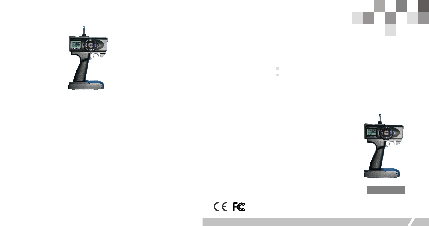
Thank you for purchasing our‘T P C A R E’R/C system.
Before using, read this manual carefully.
O
PPM/FM Radio Control System
Introduction Manual
RADIO CONTROL SYSTEM N-4Q R/C
R/C Introduction Manual
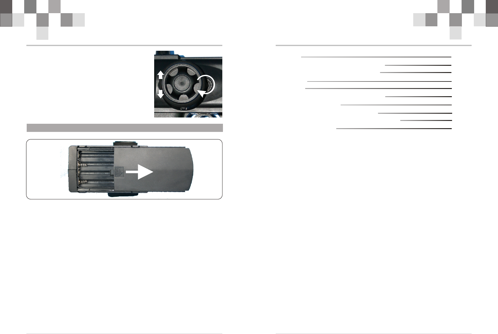
3.1 Handling Procedure For Batteries
7
! Battery Replacement
1.Remove the battery cover from the transmitter by sliding it in the direction of the arrow .
2. Remove the used batteries.
3.Load the new AA size batteries. Pay very close attention to the polarity marking and
reinsert accordingly.
4 .Slide the battery cover back onto the case.
! Caution
Always be sure your reinsert the batteries in the correct polarity order. If the batteries are
loaded incorrectly, the transmitter may be damaged.
When the transmitter is not used , always remember to remove the batteries. If the
batteries do happen to leak, clean the batteries case and contacts thoroughly. Make sure the
contacts are free of corrosion.
! Battery Disposal
Some countries require special handling of used of batteries ,please contact the agencies
responsible for recycling hazardous wastes in your local area.
! Battery low voltage alarm indicator.
R/C Introduction Manual
Caution
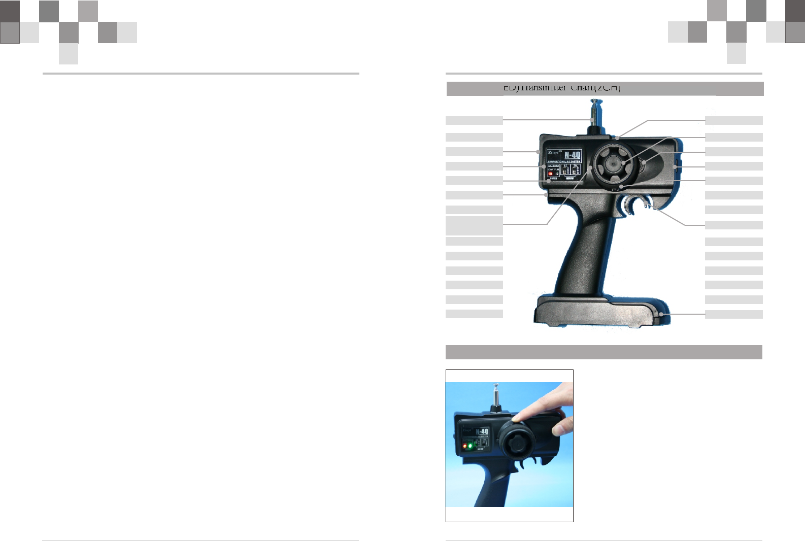
N-4Q ) Transmitter Chart
N-4Q )Transmitter Chart
N-4Q )Transmitter Chart
N-4Q ) m
1.1 (LCD (2CH)
1.2 (LCD (3ch)
1.2 Menu
1.3 Trim
2.1 (LED (2CH)
2.2 (LED enu
3.1 Handling Procedure For Batteries
4.1 Connection between Receiver and Servos
Technology Data
1
2
3
4
5
6
6
7
8
8
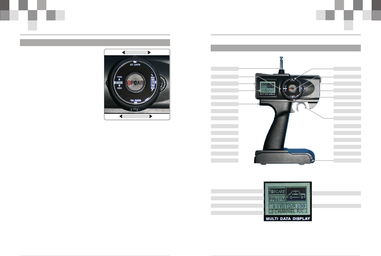
4.D/R Knob(20%~100%)
Clockwise, steering servo travel will be increased.
Anticlockwise, steering servo travel will be decreased.
5.ST.&TH. Trim Adj.
Push “ST.&TH. Trim Adj.” button up or down,Steering
Trim&Throtter Trim in the middle.
20%
100%
R/C Introduction Manual
1.4 Trim
5
!Please start the motor or the engine while
marking the adjustment of these settings.
1 .Connect the receiver, servos, and other
components and then turn on the power
switches to transmitter and receiver.
2.Be sure the Steering trim and Throttle trim
on the transmitter are at their neutral position.
3.When turning on the transmitter, please
make sure the transmitter antenna is
completely extended. Turn on the
transmitter before turning on the receiver,
while turn off the receiver before turning
off the transmitter.
Steering Trim
Steering neutral adjustments can be made by moving the steering trim knob to the left or
the right.
!Racers Tip
Always check and be sure the servo is at its neutral position before installing a servo.
Adjust the servo horn hole position and linkage so both are parallel. When a servo saver is
used place it as closer to center position as possible. Be sure the steering trim on the
transmitter at the neutral position.
!Trim Operation And Maximum Trav.
Changing the trim can effect the overall settings, when adjustments are made with the
trims, please recheck your installation for maximum servo travel.(Sreeting EPA right side
and left side ).
!When Trim movement goes to extremes
That means if you make a lot of trim movement to get a servo to the neutral position,
please reposition the servo horn or servo saver on the servo and inspect your linkage
installation.
Throttle Trim
Throttle neutral adjustments can be made by moving the throttle trim to the left or the
right.
! Racers Tip
When using a electronic speed control, please set the throttle trim to neutral and make
adjustments to the speed control. On a gas powered model, set the trim to neutral and
adjust the linkage to the point where carburetor is fully closed in accordance with the
engine instruction manual.
! Trim Operation and Travel
Trim adjustments will effect the overall servo travel, so please check the (back-ward)
movement after the adjustment
! When trim movement is goes to extremes
That means if you make a lot of the trim movement to get the servo to the neutral
position, please recenter the servo horn closer to the neutral position and inspect your
throttle linkage.
Steering Trim
Throtter Trim
R/C Introduction Manual 2
!When the voltage is lower than 8.6V,the voltmeter will flash with low voltage
alarming.
!ST. D/R Knob(20%~100%)
Clockwise, steering servo travel will be increased.
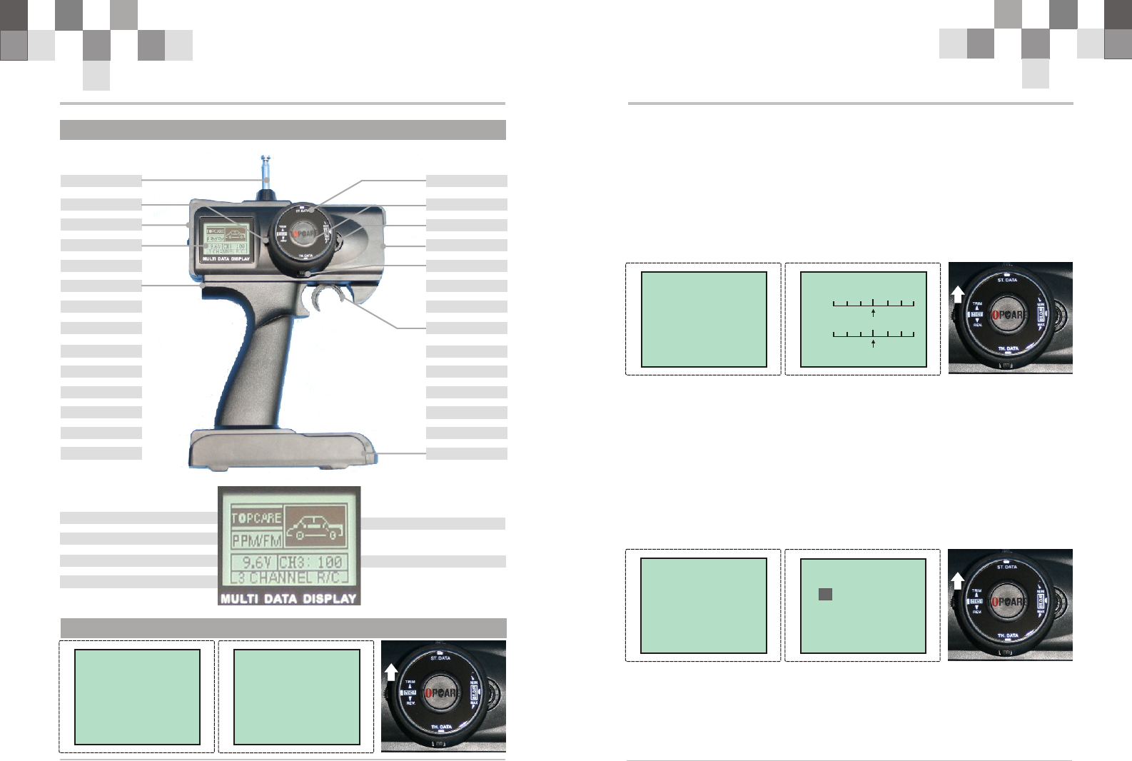
Antenna
Menu SW Steering Wheal
Crystal(Tx)
Power SW
Throtter Trim
LCD
Steering D/R Knob
Steering Trim
Throtter Trigger
Battery Cover
Charging Jack
1.1 (2CH)N-4Q(LCD) Transmitter Chart
Moudle
Steering D/R
油门微调显示
Mode
LOGO
Channel
Voltage
2CH
Antenna
Menu SW Steering Wheal
Crystal(XTAL)
Power SW
Throtter Trim
LCD
Ch3 Knob
Steering Trim
Throtter Trigger
Battery Cover
Charging Jack
R/C Introduction Manual R/C Introduction Manual 43
1.3 Menu
!Push “MENU” button down to access “FUNCTION”.
!Push “MENU” button up to access “SUB. TRIM”.
!Push “ST. DATA” button left or right, the “ST.” arrow in LCD will move accordingly.
The “ST.” arrow will keep moving if the button is pushed continuously.
!Push “TH. DATA” button left or right, the “TH.” arrow in LCD will move accordingly.
The “TH.” arrow will keep moving if the button is pushed continuously.
!Push “MENU” button up to exit and “SUB TRIM” will be saved simultaneously.
1.2 (LCD)N-4Q Transmitter Chart(3CH)
Moudle
Ch3
油门微调显示
Mode
LOGO
Channel
Voltage
3CH
2. SUB TRIM
ST. ST.
TH. TH.
[Sub.Trim ][Sub.Trim ]
REV. FUN.
TRIM FUN.
STOR FUN
EXIT
REV. FUN.
TRIM FUN.
STOR FUN
EXIT
[FUNCTION] A[FUNCTION] A
>>
!Push “MENU” button down to access “FUNCTION”.
!Push “MENU” button up to access “STOR FUN”.
!Push “TH. DATA” button right or left, select mode memory .
!Pushing “MENU” button up to exit and “STOR FUN” will be saved simultaneously.
3. STOR MODEL
[STOR MODEL][STOR MODEL]
REV. FUN.
TRIM FUN.
STOR FUN
EXIT
REV. FUN.
TRIM FUN.
STOR FUN
EXIT
[FUNCTION] A[FUNCTION] A
>>
A B C D
E F G H
I J K L
A
[REV][REV]
REV. FUN.
TRIM FUN.
STOR FUN
EXIT
REV. FUN.
TRIM FUN.
STOR FUN
EXIT
[FUNCTION] A[FUNCTION] A
>> TH. ST.
NOR REV
!Push “MENU” button down to access “FUNCTION”.
!Push “MENU” button up to access “REV”.
!Push “ST. DATA” button right, “ST” channel reversed.
!Push “TH. DATA” button right, “TH” channel reversed.
!Pushing “MENU” button down to exit and “REV” will be saved simultaneously.
R/C Introduction Manual
1
! To work your R/C with your models correctly and safely, read this manual
carefully and keep it in a safe way as a reference introduction in the future.
! Warning:
1. This product is only equipped for radio controlled models;
2. The usage of this product should be approved by local relevant law or
regulations;
3. We will be not responsible for the damages caused by unauthorized
modification,adjustment or replacement of parts of this product;
4. The manual may be altered without prior notice. Please contact us if you have
any corrections or clarifications that should be made in the manual.
! Because of disturbance, do not work your radio control system simultaneously
with others at the same frequency.
! Before starting the transmitter, make sure the transmitter batteries are well
loaded .The voltage of transmitter batteries never be lower than 8.6V. And please
check and confirm that the servos are all well and properly connected.
! Please take off batteries from transmitter after flying and during the transportati-
on.
! Please check and have a test on control surfaces to confirm the transmitter
handling of each part prior to each takeoff. The frequencies of the module and
the receiver should be the same.
! Keep the radio system away from moist, high temperature and strong shake. Do
not clean the product with solvent.
! Do not fly your models near airfields, schools, hospitals, residences, power
transmission network, communication facilities and other places that are
forbidden for starting the transmitter. Please stop flying your models with the
radio on rainy or windy days, or at night.
! Do not fly the models when you are tired, sick , intoxicated,or not in good spirit.
! The antenna do not touch anything else when power switch is turned on. Do not
leave this product and its accessories within the reach of small children.
! Please use this product according to your local relevant law or regulation, we are
not responsible for any incidents or damages.
Caution
R/C Introduction Manual 6
2.1 (LED (2CH)N-4Q )Transmitter Chart
2CH
Reverse SW
Antenna
Steering Wheal
Crystal(XTAL)
Power SW
Throtter Trim
LED
Steering Trim
Throtter Trigger
Battery Cover
Charging Jack
Steering D/R Knob
2.2 (LED enuN-4Q ) m
1.Power
When turn on power, the power light will be red.
When the voltage is lower than 8.6V, the power
light will be twinkling with audible alarm. Please
use new batteries.
2.Reverse
Reverse switch is down, channels are in reversed
mode.
Reverse switch is up, channels are normal.
3.Trim
The green light will be twinkling when “ST.” or
“TH.” Trim is moved left or right.
If the green light do NOT be twinkling when “ST.”
or “TH.” Trim is moved left or right, the trim travel
is beyond its scope. (the travel scope is 5°
approximately )
ST.&TH.
Trim Adj.
R/C Introduction Manual 8
R/C Introduction Manual
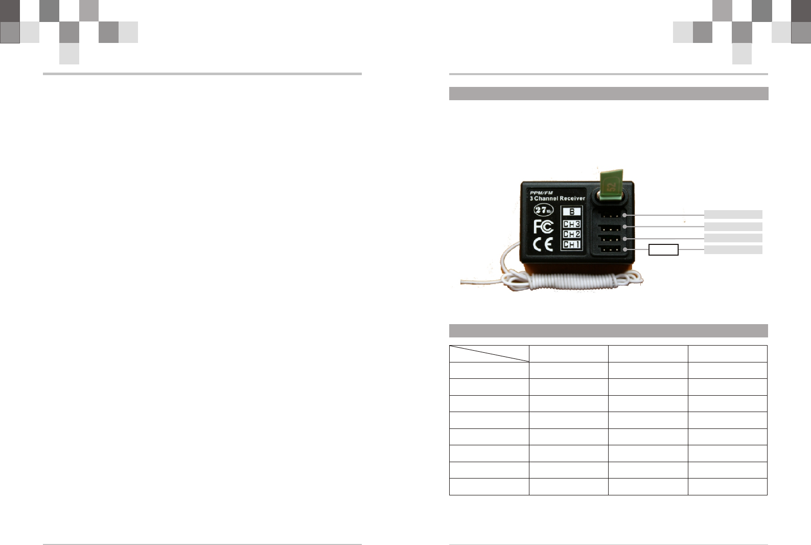
4.1 Connection between Receiver and Servos
SERVO3(CH3)
SERVO1(TH.)
SERVO2(ST.)
BATT.( 4.8V)
ESC
!The receiver and the servos must be properly connected for your models. The “CH3”
channel is useless for 2ch trigger transmitter.
!If ESC in the model can support power, connect it with “CH1” channel directly.
+-
2-CH R/C 2-CH R/C 3-CH R/C
Type: N-4Q N-4Q N-4Q
Specification: LCD LED LCD
Code format: PPM/FM PPM/FM PPM/FM
Channels: 2 2 3
Frequency: 27/40/72/75M 27/40/72/75M 27/40/72/75M
DC: 9.6V,≤200mA 9.6V,≤200mA 9.6V,≤200mA
Measurement: 295*204*105mm 295*204*105mm 295*204*105mm
Net weight: 530g 530g 530g
(One type of them) (One type of them) (One type of them)
Technology Data
(packing meas.) (packing meas.) (Packing meas.)