Guangzhou Chiyuan Electronic N-4Q N-4Q User Manual
Guangzhou Chiyuan Electronic Co.,Ltd N-4Q Users Manual
Contents
- 1. Users Manual
- 2. User Manual
User Manual
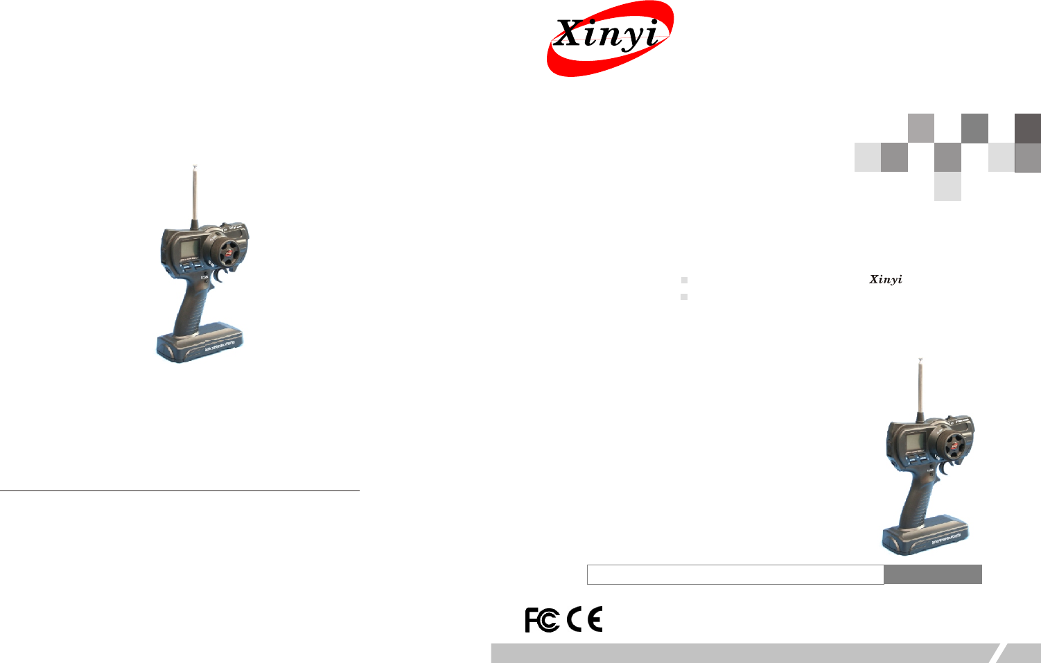
N-4Q R/C
DIGITAL PROPORTIONAL R/C SYSTEM
Thank you for purchasing our‘ ’R/C system.
Before using, read this manual carefully.
3 -CH PCM/PPM Radio Control System
Introduction Manual
Guangzhou Chiyuan Electronic Co., Ltd
Add: 2/F., No. 1 Bldg., Boyi Industrial Garden, 4th Gongye Rd.
Zhicun, Dashi Street, Panyu Dis., Guangzhou, China
Tel: +86-20-34796226;34797226
Fax: +86-20-34796116
Website: www.chiyuan.net
E-mail: chiyuan_gz@126.com
R/C Introduction Manual
Table of Contents
Caution
1.1 Basic Introduction
1.2 N-4Q Transmitter Chart
2.1
5
2 6
2 7
2 8
2 9 TH
2 10.1
2 10.2
2 10.3
2 10.4
2 10.5
2 10.6
2 11
MENU FUNCTION
2. 2 Characteristics of system
2. 3 EPA
2. 4 D/R
2. SUB TRIM
. REV
. MDL
. ST.C
. .C
. SYS (MOD)
. SYS (B-MIX)
. SYS (MIX)
. SYS (HOLD)
. SYS (F/S)
.SYS (RESET)
.Trim ADJ.
3.1 Handling Procedure For Batteries
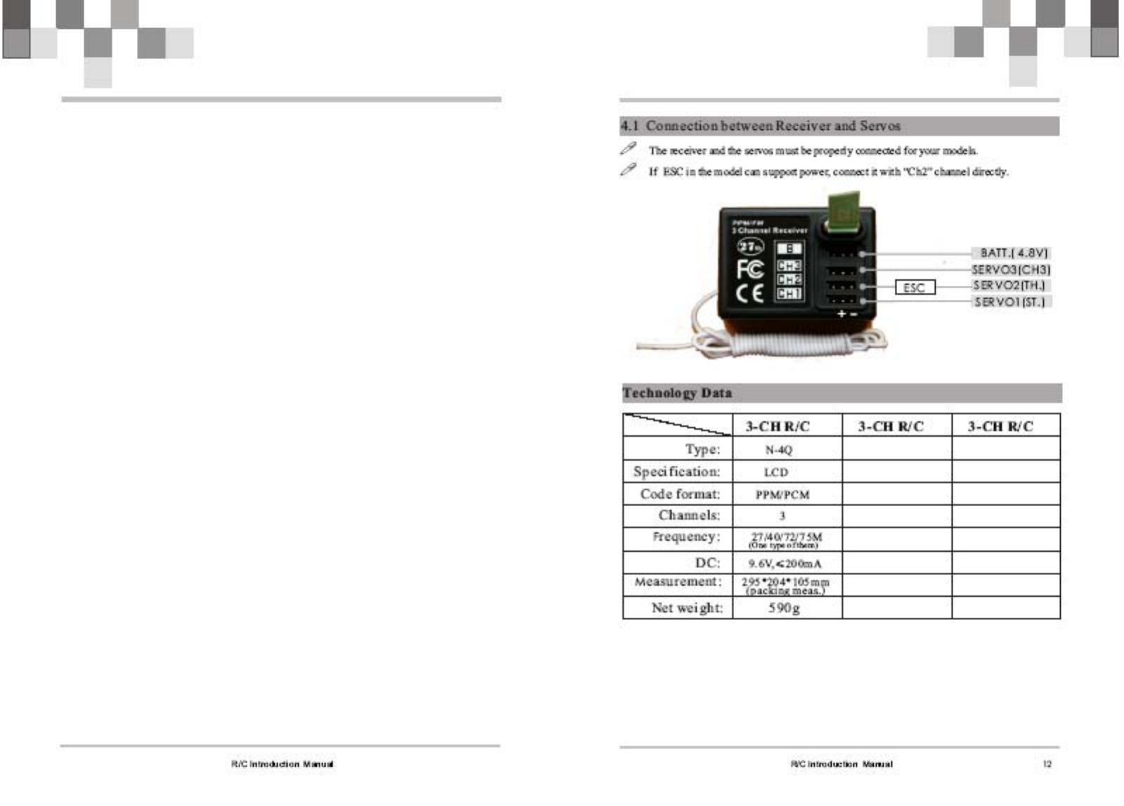
4.1 Connection between Receiver and Servos
Technology Data
1
2
2
3
3
4
4
4
5
5
6
6
7
7
8
8
9
9
10
11
12
12
R/C Introduction Manual
3.1 Handling Procedure For Batteries
11
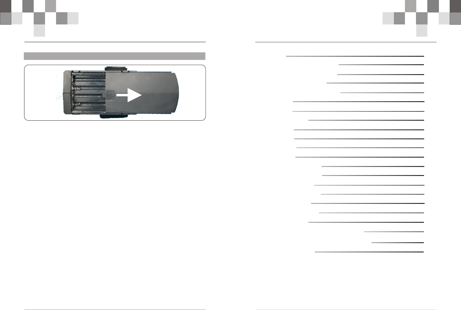
! Battery Replacement
1.Remove the battery cover from the transmitter by sliding it in the direction of the arrow .
2. Remove the used batteries.
3.Load the new AA size batteries. Pay very close attention to the polarity marking and
reinsert accordingly.
4 .Slide the battery cover back onto the case.
! Caution
Always be sure your reinsert the batteries in the correct polarity order. If the batteries are
loaded incorrectly, the transmitter may be damaged.
When the transmitter is not used , always remember to remove the batteries. If the
batteries do happen to leak, clean the batteries case and contacts thoroughly. Make sure the
contacts are free of corrosion.
! Battery Disposal
Some countries require special handling of used of batteries ,please contact the agencies
responsible for recycling hazardous wastes in your local area.
! Battery low voltage alarm indicator.
R/C Introduction Manual 2
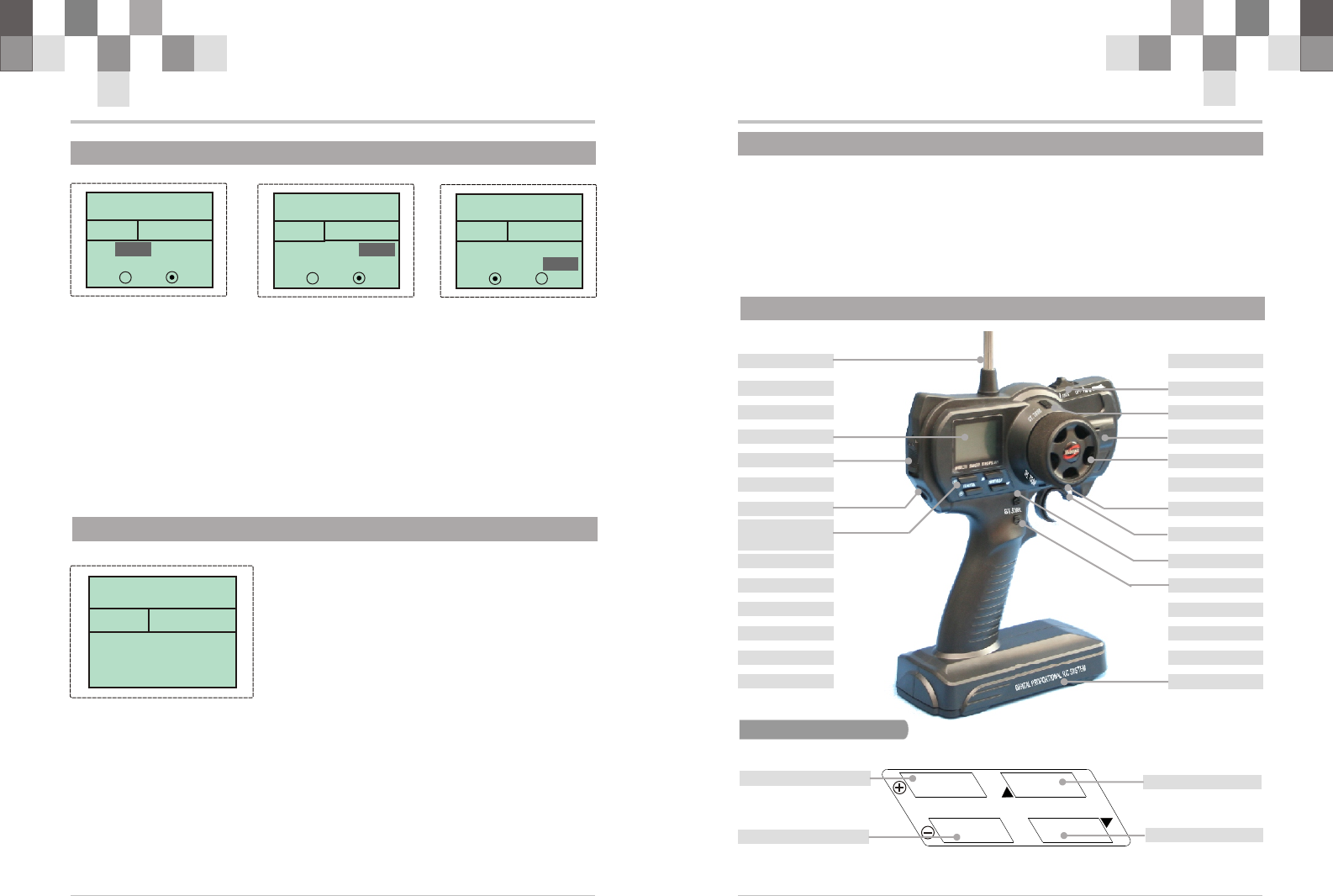
1.2 N-4Q Transmitter Chart
Steering Wheal
Crystal(Tx)
TH. Trim
ST. Trim
TH. Trigger
电池仓
1.1 Basic Introduction
N-4Q is a 3 channel pistol grip radio controller. Channel 1: rudder, Channel 2:
throttle, Channel 3: AUX
N-4Q will start the initial inspection of the system when it is switched on. It takes
about 30 seconds if the RC is used for the first time. Otherwise, it takes only 1~3 seconds
for the inspection.
MENU
AUX Channel
ST. D/R
MENU
EXIT ENTER
MODE&DATA
EXIT
ENTER
Battery Box
MODE&DATA +
MODE&DATA –
Antenna
LCD
TH. HOLD
Power SW
Charging Jack
R/C Introduction Manual
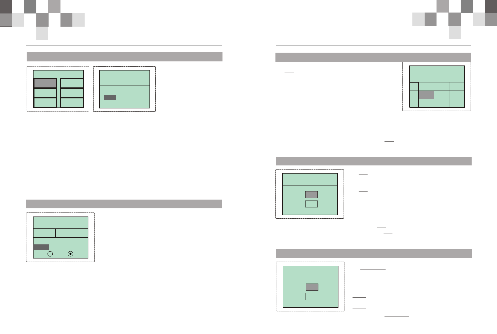
2.10.5 SYS (F/S)
9
- Fail safe function comes into effect when receiver does not receive the data. This
function does not work in PPM mode. The servo value of rudder channel and throttle
channel in the fail status can be set through fail safe function.
- In the power on interface, press “ENTER” to enter function interface, and select
“SYS” by “+” or “-”. Now press “ENTER” to enter “SYSTEM” menu and select “F/S” by
“+” or “-“. and then press “ENTER” and come to the fail safe interface.
- In “ST” line, to set the servo value of rudder channel at fail safe status. The value: -
120% to +120%. ACT/INH is the function of allow/prohibit. When selecting “ACT”, the
rudder servo will be locked at the set value when failing.
- In “TH” line, to set the throttle servo value. The same way as in “ST” line.
- “EN” . is the start or close switch of fail safe function.
SYSTEM SYSTEM
F/S
ST: 0 % INH
TH: 0 % INH
EN: ON OFF
SYSTEM SYSTEM
F/S
ST: 0 % ACT
TH: 0 % INH
EN: ON OFF
SYSTEM SYSTEM
F/S
ST: 0 % INH
TH: 0 % INH
EN: ON OFF
SYSTEM SYSTEM
RESET
Reset System ?
2.10.6 SYS (RESET)
- All the setting in the system will be back to the
default status by this reset function. It takes about 30
seconds.
- In the power on interface, press “ENTER” to
enter function interface, and select “SYS” by “+” or “-
”. Now press “ENTER” to enter “SYSTEM” menu and
select “RESET” by “+” or “-“. and then press “ENTER”
and come to the system reset interface.
- All the system data will come back to the default value by pressing “ENTER”.
Remark: when the remote controller shows disordered code in the process of reset
function, recovery operation is needed.
R/C Introduction Manual 4
!EPA is used to adjust the maximum turning range of
servos, including Steering turning range, the
highest point of throttle as well as brake range. And
at the same time, it can adjust the output range of
the third channel.
EPA adjusting value range: 0~120 %, default is
100%
E P A E P A
ST TH AUX
100% 100% 100%
2.3 EPA
2.4 D/R
100% 100% 100%
F
B
!D/R is used to change the action range of steering
servo when turning the steering wheel. Increasing D/R
will make the steering wheel action more sensitive.
D/R adjusting value range: 0~120%, default is
100%
1.Press “ENTER” in the power on interface, and
enter function menu interface. Press “+” or “-“ to
choose D/R, and press “ENTER” to enter D/R
adjusting interface.
ST D/R ST D/R
POS0:100 %
POS1: 70 %
2.5 SUB TRIM
SUB TRIM SUB TRIM
ST : 0
TH : 0
1.Press “ENTER” in the power on interface and enter function menu. Press “+” or “-”
to choose “EPA”. And press “ENTER” and enter EPA adjusting interface.
2.Press “ENTER” to choose each adjusting item, and then press “+” to increase and “-
” to decrease the value of the corresponding item.
3.Press “EXIT” to save your setting and leave EPA interface, and back to the function
menu interface.
2.Press “+” to increase and “-” to decrease D/R value.
3.Press “EXIT”to save your setting and leave D/R interface, and back to the function
menu interface.
!SUB TRIM adjusting value range: -100~+100%,
default is 0%
1.Press “ENTER” in the power on interface, and
enter function menu interface. Press “+” or “-“ to
choose TRIM, and press “ENTER” to enter SUB
TRIM adjusting interface.
2.Press “+” to increase and “-” to decrease SUB
TRIM value.
3.Press “EXIT”to save your setting and leave SUB TRIM interface, and back to the
function menu interface.
R/C Introduction Manual
7
2.10.1 SYS (MOD)
SYSTEM SYSTEM
2.10.2 SYS (B-MIX)
SYSTEM SYSTEM
MOD B-MIX
F/S RESET
MIX HOLD
In the power on interface, press “ENTER” to enter function interface, and select
“SYS” by “+” or “-”. Now press “ENTER” to enter “SYSTEM” menu and select “MOD”
by “+” or “-“. and then press “ENTER” and come to the modulation interface.
When mode is FM, PPM or PCM can be selected in this menu.
B-MIX
BRAKE MIX:
RATE : 100 %
EN: ON OFF
!Brake Mix is used when two servos are equipped for
braking. If this function is allowed in setting, the third
channel(AUX) is used for brake mix channel, and the
switch doesn't work.
In the power on interface, press “ENTER” to enter
function interface, and select “SYS” by “+” or “-”. Now
press “ENTER” to enter “SYSTEM” menu and select
“B-MIX” by “+” or “-“. and then press “ENTER” and
come to Brake Mix setting interface.
“RATE” is the rate of brake end between 3rd channel and 2nd channel. Value range:0~
120% ;Default value:100% .
“EN” is the start or close switch of this function. Select “ON” to start the function,
and “OFF” to close the function.
Leave the setting by pressing “EXIT” when the setting is finished.
SYSTEM SYSTEM
MOD
RST
SYSTEM SYSTEM
MOD
MODULATION:
PPM PCM
R/C Introduction Manual R/C Introduction Manual
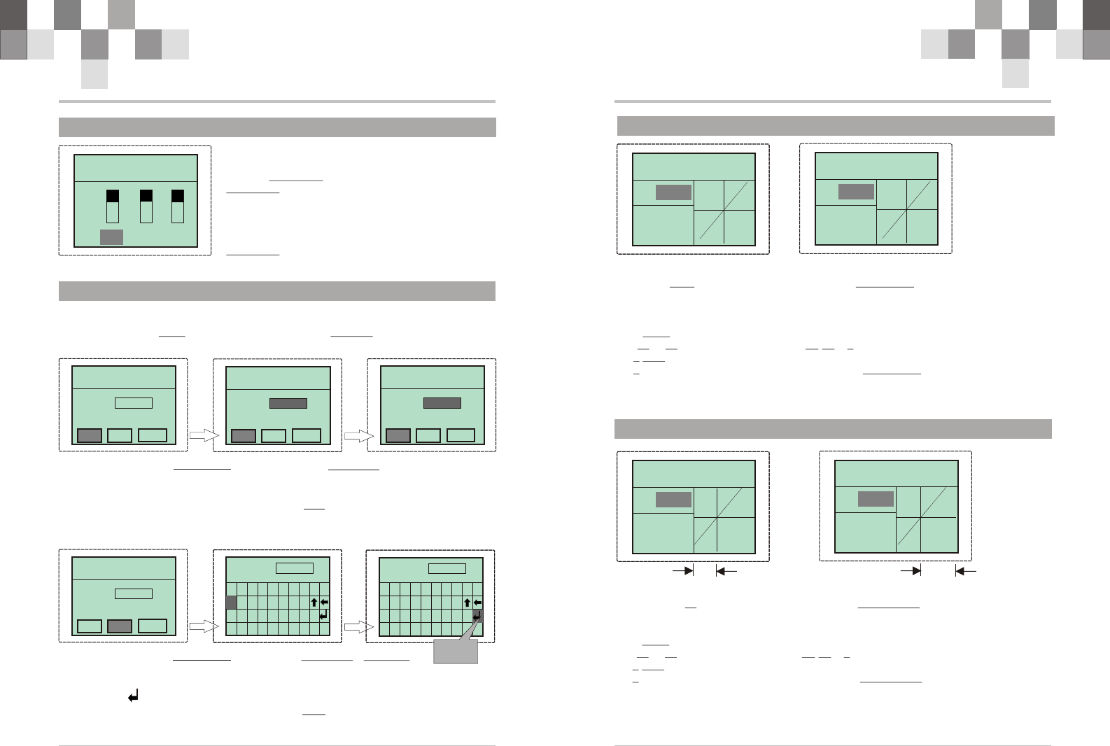
2.6 REV
1.Press “ENTER” in the power on interface, and
enter function menu interface. Press “+” or “-“ to
choose REVERSE, and press “ENTER” to enter
REVERSE adjusting interface.
2.Press “ENTER” to choose each Channel.
3.Press “+” to increase and “-” to choose “REV” or
“NOR”.
4.Press “EXIT”to save your setting and leave
REVERSE interface, and back to the function menu
interface.
REVERSE REVERSE
ST TH AUX
R E V
NOR
2.7 MDL
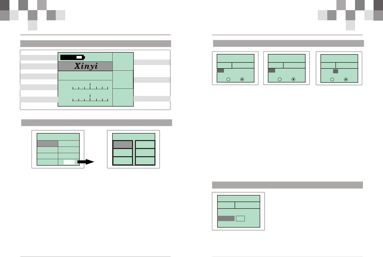
2.8 ST.C
STEERING STEERING
M:LINE
M:0 %
H:100%
STEERING STEERING
M:LINE
L :0 %
H:100%
STEERING STEERING
M:EXP
R:0 %
STEERING STEERING
M:LINE
M:0 %
H:100%
THROTTLE THROTTLE
M:LINE
L :0 %
H:100%
THROTTLE THROTTLE
M:EXP
R:0 %
2.9 TH.C
65
MODEL MODEL
SEL EDT CPY
MOL.N: Mod00
MODEL MODEL
SEL EDT CPY
MOL.N: Mod00
MODEL MODEL
SEL EDT CPY
MOL.N: Mod01
“ENTER” “+ or -”
!Press “ENTER” in the power on interface, and enter function menu interface. Press
“+” or “-“ to choose MDL, and press “ENTER” to enter MODEL adjusting interface.
1.Press “ENTER” to choose “mod00”.(SEL)
2.Press “+” or “-”to choose “mod00~mod15”
3.Press “EXIT”to save your setting and leave SEL interface, and back to the function
menu interface.
MODEL MODEL
MOL.N: Mod00
MOL.N: A
“ENTER” “+ or -”/“ENTER”
1.Press “+” or “-”to choose “EDT”.
2.Press “ENTER” to enter rename mode ,Press “+” or “-”to choose “0.1.2....I”
3.The “ ”is OK!
4.Press “EXIT”to save your setting and leave EDT interface, and back to the function
menu interface.
SEL EDT CPY
S T UVWXYZ
J K LMNOP Q R
0 1 2 3 4 5 6 7 8 9
AB C DE F GH I
MOL.N: A|
R S T UVWXYZ
I J K LMNOP Q
0 1 2 3 4 5 6 7 8 9
AB C DE F GH
MOL.N: A
S T UVWXYZ
J K LMNOP Q R
0 1 2 3 4 5 6 7 8 9
AB C DE F GH I
MOL.N:
ADAM|
0 1 2 3 4 5 6 7 8 9
ENTER
1.Press “ENTER” in the power on interface and enter function menu. Press “+” or “-”
to choose “ST.C”. And press “ENTER” and enter STEERING adjusting interface.
2.Press “+” or “-” to choose “LINE”or “EXP”, Press “ENTER” to choose “L”or
“H”,and then press “+” to increase and “-” to decrease the value of the corresponding
item.
3.LINE adjusting value range:
(L):0~50 %, default is 0% (H):50~100 %, default is 100%
4.EXP adjusting value range: -100%~+100 %, default is 0%
5.Press “EXIT”to save your setting and leave STEERING interface, and back to the
function menu interface.
1.Press “ENTER” in the power on interface and enter function menu. Press “+” or “-”
to choose “TH.C”. And press “ENTER” and enter THROTTLE adjusting interface.
2.Press “+” or “-” to choose “LINE”or “EXP”, Press “ENTER” to choose “L”or “H”
and then press “+” to increase and “-” to decrease the value of the corresponding item.
3.LINE adjusting value range:
(L):0~50 %, default is 0% (H):50~100 %, default is 100%
4.EXP adjusting value range: -100%~+100 %, default is 0%
5.Press “EXIT”to save your setting and leave THROTTLE interface, and back to the
function menu interface.
R S T UVWXYZ
I J K LMNOP Q
AB C DE F GH
30%(max) 70%(max)
R/C Introduction Manual 8
2.10.3 SYS (MIX)
2.10.4 SYS (HOLD)
SYSTEM SYSTEM
MIX
ST: L 50 R 50
ST : L 50 R 50
EN: ON OFF
!MIX allows three custom channels mixing. There are main channel and sub-channel
in the mix selection. The servo travel value of the sub channel is changed along with the
change of the main channel according to the setting rate.
- In the power on interface, press “ENTER” to enter function interface, and select
“SYS” by “+” or “-”. Now press “ENTER” to enter “SYSTEM” menu and select “MIX”
by “+” or “-“. and then press “ENTER” and come to the mix setting interface.
- Firstly main channel setting. Select channel No. (ST, TH, AUX) by “+” or “-“. L
and R separately correspond to the rate of Left and Right servos of the main channel mix
- Secondly sub channel setting. Select channel No. (ST, TH, AUX) by “+” or “-“. L
and R separately correspond to the rate of Left and Right servos selected in the sub
channel.
- “EN” . is the start or close switch of this function. Select “ON” to start the function,
and “OFF” to close the function.
For example: current setting: ST: L 50% R 30%
TH: L 20% R 50%
EN: select “ON”
If throttle servo is 60% on the right and rudder servo is 50% on the right, and then
after setting, throttle servo is: 50*30%+60%*50%=45%.
- Throttle servo will act along with the action of rudder servo.
Leave the setting by pressing “EXIT” when the setting is finished.
SYSTEM SYSTEM
MIX
TH: L 50 R 50
ST : L 50 R 50
EN: ON OFF
SYSTEM SYSTEM
MIX
TH: L 50 R 50
ST : L 50 R 50
EN: ON OFF
SYSTEM SYSTEM
VALUE : 0 %
HOLD
THRO.HOLD:
- Throttle hold can be performed by pressing the
switch to stop the engine. It can be performed for
accident braking. When pressing the switch, throttle
trigger doesn't work until the switch is pressed again.
- In the power on interface, press “ENTER” to
enter function interface, and select “SYS” by “+” or
“-”. Now press “ENTER” to enter “SYSTEM” menu
and select “HOLD” by “+” or “-“. and then press
“ENTER” and come to the throttle hold interface.
- “VALUE” refers to servo value in throttle hold position. Value range:-120~ +120%
;Default value:0% .
R/C Introduction Manual
3
2.2 Characteristics of system
2.1 MENU FUNCTION
FUNCTIO N FUNCTIO N
Mod00Mod00
10.2v D/R:
100
HLD:
OFF
MOD:
HRF
ST. ST.
TH. TH.
V
LOGO
MODEL NAME
ST. Trim
TH. Trim MODE(2.4G)
TH. HOLD
ST. D/R
EPA D/R
MDL ST.C
!Respectively adjust EPA of three channels
! Support D/R function of Steering channel
! Neutral trims of Steering and throttle
!Respectively set the reverse of the three channels
!Choose EXP curve or LINE curve freely, and line curve can adjust the two ends.
!Custom model name, 5 letters at most for each name, 16 memories model data. Each
data can be duplicated between them to avoid repeat establishment.
!Battery change reminding function.
TRIM REV
SYSTEM SYSTEM
MOD B-MIX
F/S RESET
MIX HOLD
TH.C SYS

R/C Introduction Manual
2.11 Trim ADJ.
10
!Please start the motor or the engine while marking the adjustment of these settings.
1 .Connect the receiver, servos, and other components and then turn on the power
switches to transmitter and receiver.
2.Be sure the Steering trim and Throttle trim on the transmitter are at their neutral
position.
3.When turning on the transmitter, please make sure the transmitter antenna is
completely extended. Turn on the transmitter before turning on the receiver, while
turn off the receiver before turning off the transmitter.
Steering Trim
Steering neutral adjustments can be made by moving the steering trim knob to the left or
the right.
!Racers Tip
Always check and be sure the servo is at its neutral position before installing a servo.
Adjust the servo horn hole position and linkage so both are parallel. When a servo saver is
used place it as closer to center position as possible. Be sure the steering trim on the
transmitter at the neutral position.
!Trim Operation And Maximum Trav.
Changing the trim can effect the overall settings, when adjustments are made with the
trims, please recheck your installation for maximum servo travel.(Sreeting EPA right side
and left side ).
!When Trim movement goes to extremes
That means if you make a lot of trim movement to get a servo to the neutral position,
please reposition the servo horn or servo saver on the servo and inspect your linkage
installation.
Throttle Trim
Throttle neutral adjustments can be made by moving the throttle trim to the left or the
right.
! Racers Tip
When using a electronic speed control, please set the throttle trim to neutral and make
adjustments to the speed control. On a gas powered model, set the trim to neutral and
adjust the linkage to the point where carburetor is fully closed in accordance with the
engine instruction manual.
! Trim Operation and Travel
Trim adjustments will effect the overall servo travel, so please check the (back-ward)
movement after the adjustment
! When trim movement is goes to extremes
That means if you make a lot of the trim movement to get the servo to the neutral
position, please recenter the servo horn closer to the neutral position and inspect your
throttle linkage.
R/C Introduction Manual
1
Caution
!To work your R/C with your models correctly and safely, read this manual
carefully and keep it in a safe way as a reference introduction in the future.
!Warning:
1. This product is only equipped for radio controlled models;
2. The usage of this product should be approved by local relevant law or
regulations;
3. We will be not responsible for the damages caused by unauthorized
modification, adjustment or replacement of parts of this product;
4. The manual may be altered without prior notice. Please contact us if you have
any corrections or clarifications that should be made in the manual.
!Please pay more attention on the parts in this manual, which marked with
“warning”.
!Because of disturbance, do not work your radio control system simultaneously
with others at the same frequency.
!Before starting the transmitter, make sure the transmitter batteries are well
loaded .The voltage of transmitter batteries never be lower than 8.6V. And
please check and confirm that the servos are all well and properly connected.
!Please take off batteries from transmitter after flying and during the
transportation.
!Please check and have a test on control surfaces to confirm the transmitter
handling of each part prior to each takeoff. The frequencies of the module and
the receiver should be the same.
!Keep the radio system away from moist, high temperature and strong shake. Do
not clean the product with solvent.
!The antenna do not touch anything else when power switch is turned on. Do not
leave this product and its accessories within the reach of small children.
!Please use this product according to your local relevant law or regulation, we
are not responsible for any incidents or damages.
NOTE: This equipment has been tested and found to comply with the limits for a
digital device, pursuant to Part 95 of the FCC Rules. These limits are
designed to provide reasonable protection against harmful interference in a
residential installation. This equipment generates, uses and can radiate radio
frequency energy and, if not installed and used in accordance with the
instructions, may cause harmful interference to radio communications. However,
there is no guarantee that interference will not occur in a particular installation.
If this equipment does cause harmful interference to radio or television reception,
which can be determined by turning the equipment off and on, the user is
encouraged to try to correct the interference by one or more of the following
measures:
-- Reorient or relocate the receiving antenna.
-- Increase the separation between the equipment and receiver.
-- Connect the equipment into an outlet on a circuit different
from that to which the receiver is connected.
-- Consult the dealer or an experienced radio/TV technician for
help.