Guardall a division of CSG Security XLK1 LCD Keypad User Manual 2
Guardall, a division of CSG Security Corp LCD Keypad 2
Contents
- 1. User Manual 1
- 2. User Manual 2
User Manual 2
21-3610 rev1.4 xL LCD Keypad Installation Instructions
CSG SecurityCorp / Sécurité CSG Corp Page 1 of 2
GUARDAL
L
5201 Explorer Drive, Mississauga, Ont., Canada. L4W-4H1
sales@ guardall.com +1 905.206.8434 | support@ guardall.com +1 905.206.8436 | Fax: +1 905.629.4970
www.guardall.com | +1 877.249.9993
The LCD keypad provides the ability to operate the entire Monitor xL™ or Chubb AFx™ system. It will also provide readouts
of the status of the systems and location and nature of alarms.
1,- # 2ABC 3DEF
45
JKL 6MNOGHI
78
TUV 9WXYPRS
Keypad LEDs
Red Flashing:
Protection ON
Solid: Partial
protection (STAY)
Green On Always
with power present. Yellow On when
trouble condition
present. Flashing when
there is no AC mains.
Red Green Yellow
ComsLost #50624ef
Enter code 42822
0Z_Q
X
X
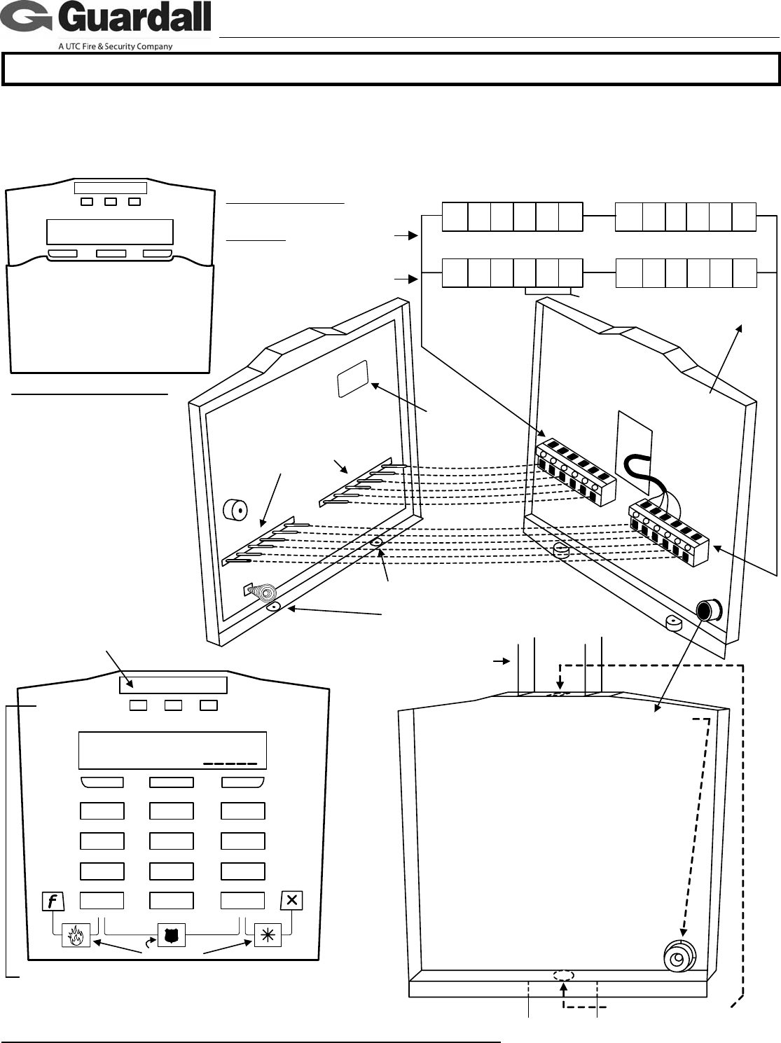
To use the keypad tamper spring as a wall tamper
break out this plastic cylinder inside the back cover.
Screw it to the wall, keeping it in the same hole as it
was attached, so the back cover fits over it.
The plastic cylinder prevents the spring from being
affected by flat objects wedged in behind the
keypad.
The additional keypad base is optional. For
installations using it there is a similar, shorter,
washer style, plastic break out.
Place it behind the plastic cylinder and screw
them down together.
Then place the holes in the base and keypad
backing over top of them.
Fit the spring inside the plastic cylinder part
and secure the keypad front to the keypad
back. The spring compressing should reset
the keypad tamper condition.
Knock outs for rectangular
conduit using additional
keypad base.
Keypad Back
Keypad Front
Circuit board pin connectors insert
into fixed terminal blocks on inside
of keypad back. This allows the
keypad to make wire connections
in the terminal blocks.
Terminal
Block
Terminal Block
Tamper Spring
Sonalert
Cable
After placing the keypad on its back
section, make sure the keypad's securing
screws (supplied) are always I N !
Standard and G-ProxII
143256
PT1 0V PT2 PT3 PT4 143256
AB0V OUT
+12V
0V
Wiegand
143256
D1 D0
14
32 56
AB0V OUT
+12V
0V 0V
PT1 PT2
Keypad Terminal Block Wiring
Module Bus
Module Bus
Output
Input 1
Input 2
Common
Wiegand Reader Data 1 and 0.
No reader LED connection.
Wall tamper
knock out
Flip Cover
Serial # sticker
for programming
into Module
Programming.
Apply dealer's logo label (supplied) in
the indented space at the top of the
keypad. Apply the Alert Button labels
as required.
Alert Labels
XXXXX
Rectangular Conduit
(Trunking)
Keypad Output
goes negative.
Interface with a
relay or power
supply. Common
their negatives
with keypad 0V.
Module Point Assignment: 8
points.
First point: Fire Alert buttons
Second point: Panic (Hold-
Up) buttons
Third point: Auxiliary Alert
buttons
Points 4 – 7 are hard wire
inputs 1 – 4 on the Standard
and G-ProxII version.
Points 4 – 5 are hard wire
inputs 1 – 2 on the Wiegand
version. All unused points
are skipped.
Point
4 – 7
Point
4 – 5
Point 1
Point 2
Point 3
Ratings:
LCD Keypad with Reader
Input: 12 – 13.8VDC, 110mA
Output: 12VDC, 1x10mA
LCD Keypad
Input: 12 – 13.8VDC, 95mA
Output: 12VDC, 1x10mA
Temp for both: -10°C to
+55°C (14°F to 131°F) @
93%
Future
Future

21-3610 rev1.4 xL LCD Keypad Installation Instructions
CSG SecurityCorp / Sécurité CSG Corp Page 2 of 2
GUARDAL
L
5201 Explorer Drive, Mississauga, Ont., Canada. L4W-4H1
sales@ guardall.com +1 905.206.8434 | support@ guardall.com +1 905.206.8436 | Fax: +1 905.629.4970
www.guardall.com | +1 877.249.9993
3 Keypad Versions
• LCD Keypad P/N 111-3610 (white), 111-3620 (gray): standard keypad includes 3 programmable alert button inputs, 4
hardwire alarm input points and 1 output point.
• LCD Keypad with internal RF reader P/N 111-3611 (white), 111-3621(gray): keypad includes 3 programmable alert button
inputs, 4 hardwire alarm input points and 1 output point. Includes a built-in RF G-Prox reader.
• LCD with external Wiegand reader Keypad P/N 111-3612 (white), 111-3622 (gray): keypad includes the capability to
connect an external Weigand reader to it. Keypad includes 3 programmable alert button inputs, 2 hardwire alarm input
points and 1 output point.
NOTE: – Double or triple card touch (badge) to LCD with external reader is the equivalent of hold a card (badge) feature at
the LCD with internal reader to e.g. turn protection on and off.
– GProxII and MIFARE readers have been proven to work acceptably when connected to the LCD with external
reader.
All versions
• Communicate with the main control unit on the SNAPP module bus.
• Backlit, 2x16 LCD display.
• Colours: white, grey.
For further keypad information, please see the Monitor xL™ or Chubb AFx™ Simplified or Advanced Installation and LCD Keypad User
Guides.
NORTH AMERICA: FCC Compliance Statement: This device complies with Part 15 of the FCC Rules. Operation is subject to the following two
conditions:(1) This device may not cause harmful interference, and (2) This device must accept any interference received, including interference that may
cause undesired operation.
This equipment has been tested and found to comply with the limits for a Class B digital device, pursuant to the limits for a Class B digital device, pursuant to
part 15 of the FCC Rules. These limits are designed to provide reasonable protection against harmful interference in a residential installation. This
equipment generates, uses, and can radiate radio frequency energy and, if not installed and used in accordance with the instructions, may cause harmful
interference to radio communications. However, there is no guarantee that interference will not occur in a particular installation. If this equipment does cause
harmful interference to radio or television reception, which can be determined by turning the equipment off and on, the user is encouraged to try to correct
the interference by one or more of the following measures:
- Reorient or relocate the receiving antenna.
- Increase the separation between the equipment and the receiver.
- Connect the equipment into an outlet on a circuit different from that to which the receiver is connected.
- Consult the dealer or an experienced radio/TV technician for help.
WARNING: Changes or modifications not expressly approved by GUARDALL could void the user's authority to operate this equipment.
Canadian Compliance Statement: This Class B digital apparatus complies with Canadian ICES-003.
EUROPE: This equipment has been tested and found to comply with the CE directive and standards for ITE equipment used in commercial and heavy
industrial applications.