HAICOM Electronics HI-505SD Bluetooth GPS User Manual Manual
HAICOM Electronics Corp. Bluetooth GPS Manual
Manual
HI-505SD
Bluetooth®
GPS Receiver
with SD interface
USER MANUAL
To insert in:
Push down to the end and hear a
“click” sound
Take out the device
2
1
To take it out:
Push down to the end and
HI-505SD will spring up
1
2
1

HI-505SD Bluetooth® GPS receiver
with SD (Security Digital) interface
Introduction:
HI-505SD is a standard Bluetooth® GPS receiver with standard
miniSD™ to SD adaptor. HI-505SD equipped with the most
recent 20 channel ultra high sensitive SiRF StarIII GPS chipsets
and wireless Bluetooth® module. Simply plug HI-505SD into
any devices equipped with the standard SD slot, user can
instantly enjoy the state of the art wireless GPS navigation. The
basic concept of the HI-505SD is that the Bluetooth®/GPS
section only taking power from the host device (like PDA,
UMPC, tabletPC, laptopPC, etc.) via the miniSD™ to SD adaptor.
In the meantime, users can still using the miniSD™ memory
card without worry about the SD slot was occupied.
1
1

HI-505SD advantages:
1.Simply plug in the HI-505SD into any SD slot from the
standard mobile device with Bluetooth® features, the device
become the all-in-one GPS navigator. HI-505SD provides the
flexibility for GPS enable in different devices and different
occasion usages.
2.Unlike other SD GPS receivers occupied the SD slot,
HI-505SD allow user to use any memory size miniSD™ card
while using the HI-505SD simultaneously.
3.Unlike most SD GPS receivers with fixed build-in memory,
HI-505SD provide the flexibility for using any separate
memory size miniSD™ card depend on how big the memory
size needed.
4.Unlike regular SDIO GPS receiver require complicated
software and driver installation, user can easily use
HI-505SD and enjoy the GPS navigation simply set up the
standard Bluetooth® connection between the devices.
5.As soon as plug in HI-505SD, user can start using the
wireless GPS navigation without worry about the Bluetooth®
GPS receiver battery life.
6. Equipped with the 20 channel ultra high sensitive SiRF
StarIII GPS module, HI-505SD can get 3D fixed in any
outdoor locations and without using the external antenna.
7. Unlike normal Bluetooth® GPS receiver moving around
dashboard while driving, HI-505SD fixed on the mobile
device and not to worry about where to place the unit.
8. HI-505SD module concept allow HI-505SD become a wired
GPS receiver. By connecting with different optional cables via
the adapting box, HI-505SD can also be used as a regular
GPS mouse. HI-505SD can not only be wireless Bluetooth
GPS receiver and also be the wired GPS receivers, like, USB
GPS receiver, RS232 GPS receiver, PDA GPS receiver, etc.
2
2
Accessories:
Standard Accessories:
1
2 3
1.
2.
3.
Model Name
HI-505SD Bluetooth® GPS receiver unit
Tool CD
User Manual
model #
HI-505SD
CDR-01
MAU-505
3
3
Optional Accessories:
1
2
1.
2.
3.
Adapting box
MMCX External antenna
PDA charging cable (plug on the adapting box)
4
4
HI-505SD Bluetooth® GPS receiver installed on cigarette
lighter outlet
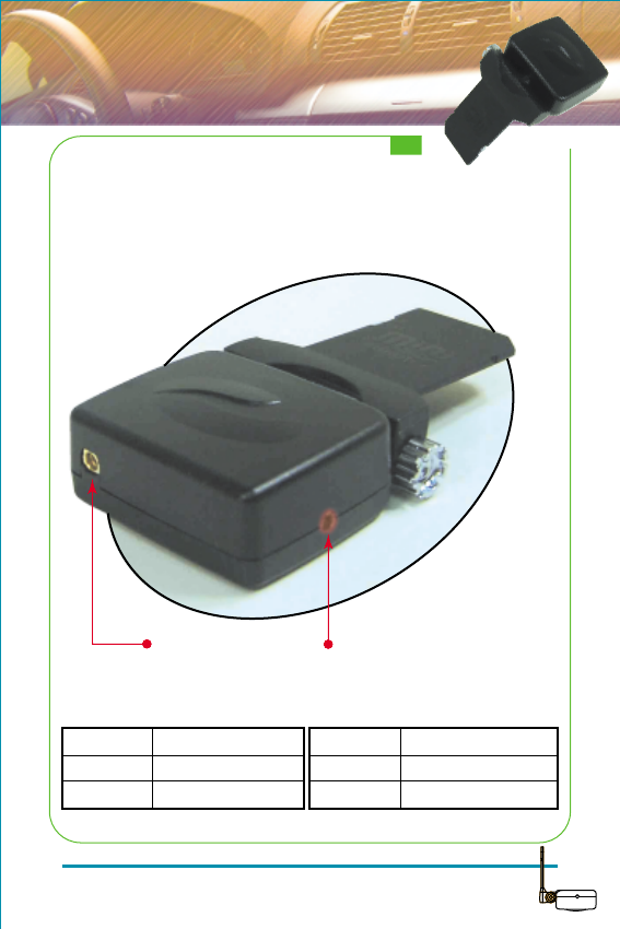
LED off
LED flashing
LED stay on
Bluetooth® switch off
Bluetooth® searching
Bluetooth® connected
LED Indicator (Blue)
LED off
LED flashing
LED stay on
Receiver switch off
GPS Position Fixed
GPS Signal searching
LED Indicator (Red)
MMCX external
antenna plug
Bluetooth® / GPS
status LED
5
5
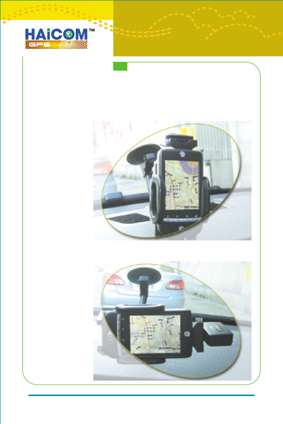
HI-505SD on a PDA:
A complete
all-in-one GPS
navigator
HI-505SD + PDA with horizontal mapping software
6
6
HI-505SD with PDA phone as a all-in-one GPS navigator
HI-505SD with laptop PC with SD Slot
7
7

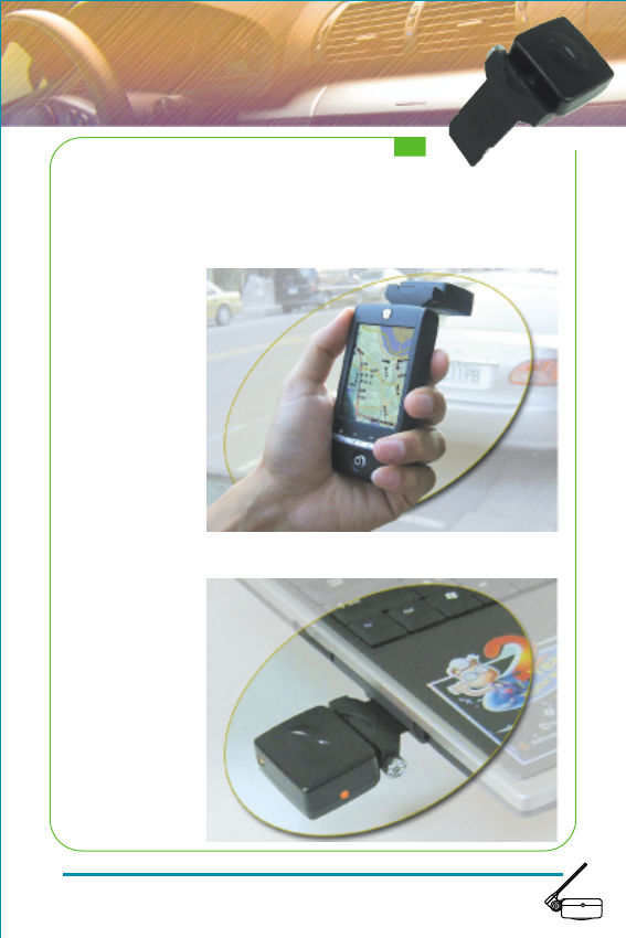
HI-505SD + PDA as a portable navigator
8
8
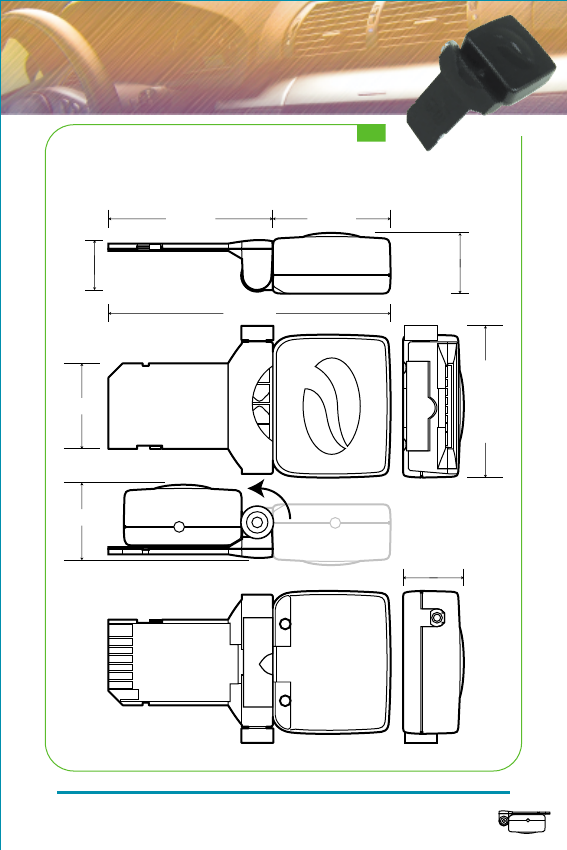
Dimension:
46mm
80mm
34mm
13mm 18mm
43mm24mm
20mm
18mm
9
9

GPS Receiver
Specification
Chipset
Interfaces
Protocol
Baud Rate
Max. Update Rate
Datum
Channel
Frequency
Hot Start
Warm Start
Cold Start
Reacquisition Tike
Position Accuracy
Macimum Altitude
Maximum velocity
Voltage
Power consumption
Antenna Type
External Antenna
Connector
Dimension
LED Indicator
SiRF Star
III
Bluetooth®
& Mini-1394
NMEA0183 GGA, GSA, GSV, RMC, GLL
4800, N, 8, 1
1 Hz
WGS84
20 channel
L1, 1575.42MHz
8 sec. Average
38 sec. Average
48 sec. Average
100 ms
15m 2D RMS, SA off
18,000m
515m/s
DC 3.3V+-10%
90mA continuous mode
Built-in active antenna
MMCX (Optional)
Fold: 46 (L) x 43 (W) x 20 (H)mm
Unfold: 80 (L) x 43 (W) x 18 (H)mm
3D Positioning (blinking) or
Searching GPS (on)
10
10

Bluetooth® Specifications:
V1.1 Compliances
Frequency Range:
Interface:
Receiver Sensetivity:
Transmitting Power:
RF Input Impedance:
Frequency hopping:
Baseband Crystal OSC:
Data Rate:
Operating Temperature:
Storage Temperature:
Transmitting Range:
Power Consumption:
2.4 ~ 2.4835 GHz
unlicensed ISM band
USB/UART/SPI
-80 dBm @ 0.1% BER
Class 2 -6 dBm ~ +4 dBm
50 ohms
1600hops/sec.
16MHz
Up to 723Kb/s
-20°C ~ +80°C
-30°C ~ +90°C
10 meters (Typical)
65 mA (Typical)
Bluetooth®
11
11
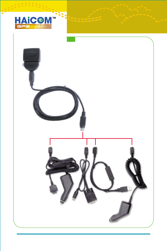
HI-505SD as a regular GPS mouse:
By connection different optional connecting
cables, HI-505SD can be all kinds of
independent wired GPS receiver solutions.
12
12
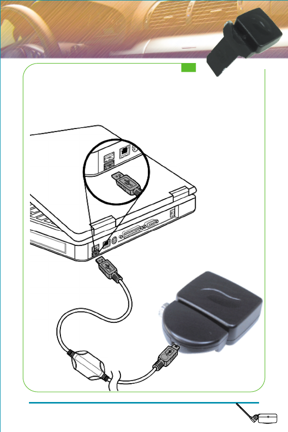
Connecting to a Notebook
Connect HI-505SD to your Notebook as a USB GPS Receiver
13
13

Disassemble
Step 1: Turn the silver knob down to the end
Step 2: The silver knob spring out
Step 3: Separate the two parts
14
14
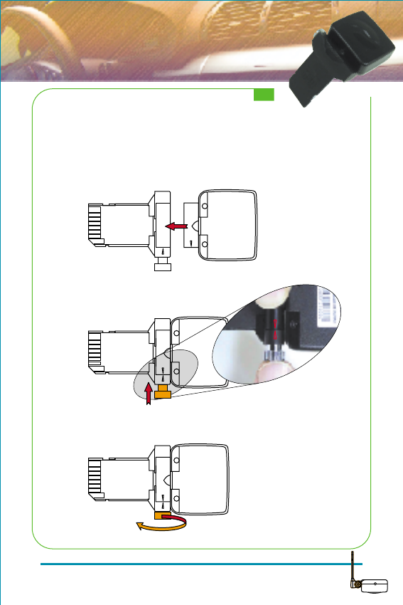
Assemble
Step 1: Put two parts in position
Step 2: Push the silver knob in
Step 3: Turn the silver knob back to other end
15
15
* Make sure two triangle align
during disassemble or assemble
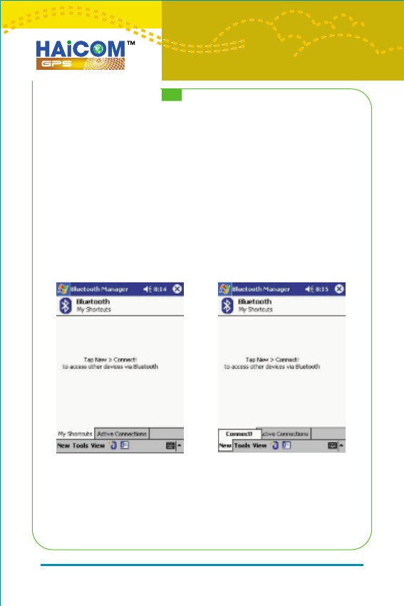
Bluetooth® Installation
Follow the instructions below to link HI-505SD to a PDA
(Personal Digital Assistant).
1. Activate “Bluetooth Manager” on your pocket PC.
Tap New, Connect, to access other devices via Bluetooth.
16
16
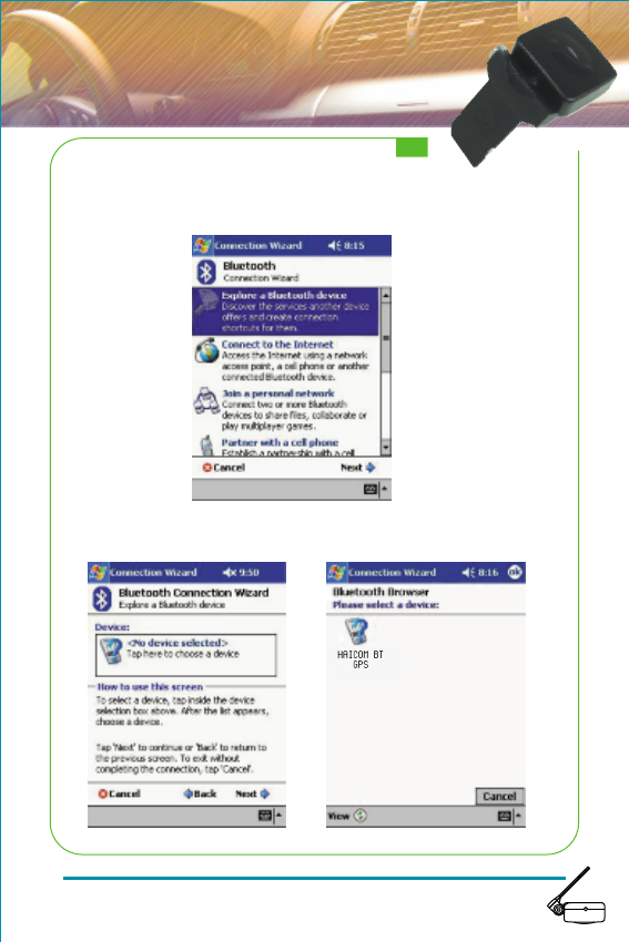
2. Search Bluetooth device “HI-505SD”. Select Explore a
Bluetooth device, and tap Next.
3. Search for the Bluetooth device. Tap Next, and then select
HI-505SD
17
17
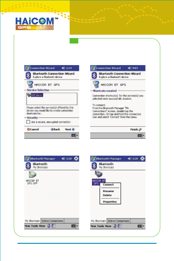
4. To establish Bluetooth link, select Connect to SPP Slave,
tap Next and then Finish.
5. Tap HAICOM BT GPS:SPP slave, and select Connect from
the dropdown menu. The installation has been completed.
18
18
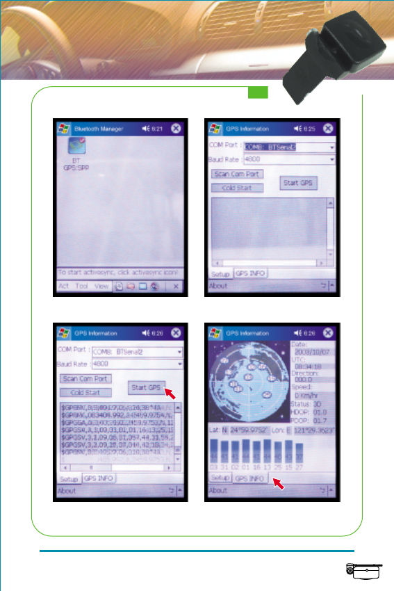
For Connected with device Select the correct com port
Start GPS, NMEA message inflow More satellites info
19
19

GPS Technical Data
ONE-PULSE-PER-SECOND (1PPS) OUTPUT
The one-pulse-per-second output is provided for applications requiring
precise timing measurements. The output pulse is 1usec in duration.
Rising edge of the output pulse is accurate to +/-1usec with respect to
the start of each GPS second. Accuracy of the one-pulse-per-second
output is maintained only when the GPS receiver has valid position fix.
The 1PPS output is always generated when the GPS receiver is
powered-on. Proper adjustment of the 1PPS output to align with the
GPS second requires calculation of the receiver clock offset and clock
drift-rate as part of the position-velocity-time (PVT) solution. When
enough satellite signals are received to generate valid position fixes,
the 1PPS output is adjusted to align with the GPS second in several
seconds. When the 1PPS output is brought in sync with the GPS
second, the 1PPS Valid Signal on the I/O pin becomes active (HIGH);
when the 1PPS output is not yet in sync with the GPS second, the
1PPS Valid Signal remains inactive (LOW).
As long as enough satellite signals are received to generate valid
position fixes, the 1PPS output remains synchronized to the GPS
second, and the 1PPS Valid Signal remains active. If signal blockage
prevents the receiver from generating valid position fix, the 1PPS
output will drift away from the GPS second and the 1PPS Valid Signal
will become inactive. Upon re-acquiring enough satellites to generate
consecutive valid position fixes, the 1PPS Valid Signal will become
active again, signaling that the 1PPS output is again synchronized with
the GPS second.
For best stable operation of the 1PPS signal, it is to be operated in
static environment having clear view of the sky.
20
20

SOFTWARE INTERFACE
This section describes the details of the serial port commands
through which the GPS module is controlled and monitored. The
serial port commands allow users to set the receiver
parameters, configure output message type, and retrieve status
information. The baud rate and protocol of the host COM port
must match the baud rate and protocol of the GPS receiver
serial port for commands and data to be successfully
transmitted and received. The default receiver protocol is
4800bps, 8 data bits, 1 stop bit, and none parity.
NMEA OUTPUT MESSAGE SPECIFICATIONS
The GPS back card supports NMEA-0183 output format as
defined by the National Marine Electronics Association
(http://www.nmea.org). The currently supported NMEA
messages for GPS applications are:
GGA
GLL
GSA
GSV
RMC
VTG
Global Positioning System Fix Data
Geographic Position Latitude / Longitude
GNSS DOP and Active Satellites
GNSS Satellites in View
Recommended Minimum Specific GNSS Data
Course Over Ground and Ground Speed
21
21

NMEA Messages
The serial interface protocol is based on the National Marine
Electronics Association's NMEA 0183 ASCII interface
specification. This standard is fully define in "NMEA 0183,
Version 3.01" The standard may be obtained from NMEA,
www.nmea.org
GGA - GPS FIX DATA
Time, position and position-fix related data (number of
satellites in use, HDOP, etc.).
Format:
$GPGGA,<1>,<2>,<3>,<4>,<5>,<6>,<7>,<8>,<9>,
M,<10>,M,<11>,<12>,*<13><CR><LF>
Example:
$GPGGA,104549.04,2447.2038,N,12100.4990,E,1,06,
01.7,00078.8,M,0016.3,M,,*5C<CR><LF>
22
22

Note: The checksum field starts with a '*' and consists of 2 characters
representing a hex number. The checksum is the exclusive
OR of all characters between '$' and '*'.
Field
1
2
3
4
5
6
7
8
9
10
11
12
13
Example
104549.04
2447.2038
N
12100.4990
E
1
06
01.7
00078.8
0016.3
5C
Description
UTC time in hhmmss.ss format,
000000.00 ~ 235959.99
Latitude in ddmm.mmmm format
Leading zeros transmitted
Latitude hemisphere indicator,
'N' = North, 'S' = South
Longitude in dddmm.mmmm format
Leading zeros transmitted
Longitude hemisphere indicator,
'E' = East, 'W' = West
Position fix quality indicator
0: position fix unavailable
1: valid position fix, SPS mode
2: valid position fix, differential GPS mode
Number of satellites in use, 00 ~ 12
Horizontal dilution of precision, 00.0 ~ 99.9
Antenna height above/below mean sea level,
-9999.9 ~ 17999.9
Geoidal height, -999.9 ~ 9999.9
Age of DGPS data since last valid RTCM
transmission in xxx format (seconds)
NULL when DGPS not used
Differential reference station ID, 0000 ~ 1023
NULL when DGPS not used
Checksum
23
23

GLL - LATITUDE AND LONGITUDE,
WITH TIME OF POSITION FIX AND STATUS
Latitude and longitude of current position, time, and status.
Format:
$GPGLL,<1>,<2>,<3>,<4>,<5>,<6>,<7>*<8><CR><LF>
Example:
$GPGLL,2447.2073,N,12100.5022,E,104548.04,A,
A*65<CR><LF>
Field
1
2
3
4
5
6
7
8
Example
2447.2073
N
12100.5022
E
104548.04
A
A
65
Description
Latitude in ddmm.mmmm format
Leading zeros transmitted
Latitude hemisphere indicator,
'N' = North, 'S' = South
Longitude in dddmm.mmmm format
Leading zeros transmitted
Longitude hemisphere indicator,
'E' = East, 'W' = West
UTC time in hhmmss.ss format,
000000.00 ~ 235959.99
Status, 'A' = valid position,
'V' = navigation receiver warning
Mode indicator
'N' = Data invalid
'A' = Autonomous
Checksum
'D' = Differential
'E' = Estimated
24
24

GSA - GPS DOP AND ACTIVE SATELLITES
GPS receiver operating mode, satellites used for navigation,
and DOP values.
Format:
$GPGSA,<1>,<2>,<3>,<3>,<3>,<3>,<3>,<3>,<3>,<3>,
<3>,<3>,<3>,<3>,<4>,<5>,<6>*<7><CR><LF>
Example:
$GPGSA,A,3,26,21,,,09,17,,,,,,,10.8,02.1,10.6*07<CR><LF>
Field
1
2
3
4
5
6
7
Example
A
3
26,21,,,09,
17,,,,,,
10.8
02.1
10.6
07
Description
Mode, 'M' = Manual, 'A' = Automatic
Fix type, 1 = not available,
2 = 2D fix, 3 = 3D fix
PRN number, 01 to 32, of satellite
used in solution, up to 12 transmitted
Position dilution of
precision, 00.0 to 99.9
Horizontal dilution of
precision, 00.0 to 99.9
Vertical dilution of
precision, 00.0 to 99.9
Checksum
25
25

GSV - GPS SATELLITE IN VIEW
Number of satellites in view, PRN number, elevation angle,
azimuth angle, and C/No. Only up to four satellite details are
transmitted per message. Additional satellite in view
information is sent in subsequent GSV messages.
Format:
$GPGSV,<1>,<2>,<3>,<4>,<5>,<6>,<7>, ... ,
<4>,<5>,<6>,<7> *<8><CR><LF>
Example:
$GPGSV,2,1,08,26,50,016,40,09,50,173,39,21,43,316,
38,17,41,144,42*7C<CR><LF>
$GPGSV,2,2,08,29,38,029,37,10,27,082,32,18,22,309,
24,24,09,145,*7B<CR><LF>
Field
1
2
3
4
5
6
7
8
Example
2
1
08
26
50
016
40
7C
Description
Total number of GSV messages to be
transmitted
Number of current GSV message
Total number of satellites in view, 00 ~ 12
Satellite PRN number, GPS: 01 ~ 32,
SBAS: 33 ~ 64 (33 = PRN120)
Satellite elevation number, 00 ~ 90 degrees
Satellite azimuth angle, 000 ~ 359 degrees
C/No, 00 ~ 99 dBNull when not tracking
Checksum
26
26

RMC - RECOMMANDED MINIMUM SPECIFIC GPS/TRANSIT DATA
Time, date, position, course and speed data.
Format:
$GPRMC,<1>,<2>,<3>,<4>,<5>,<6>,<7>,<8>,<9>,<10>,
<11>,<12>*<13><CR><LF>
Example:
$GPRMC,104549.04,A,2447.2038,N,12100.4990,E,
016.0,221.0,250304,003.3,W,A*22<CR><LF>
Field
1
2
3
4
5
6
7
8
9
10
11
12
13
Example
104549.04
A
2447.2038
N
12100.4990
E
016.0
221.0
250304
003.3
W
A
22
Description
UTC time in hhmmss.ss format,
000000.00 ~ 235959.99
Status, 'V' = navigation receiver warning,
'A' = valid position
Latitude in dddmm.mmmm format
Leading zeros transmitted
Latitude hemisphere indicator,
'N' = North, 'S' = South
Longitude in dddmm.mmmm format
Leading zeros transmitted
Longitude hemisphere indicator,
'E' = East, 'W' = West
Speed over ground, 000.0 ~ 999.9 knots
Course over ground, 000.0 ~ 359.9 degrees
UTC date of position fix, ddmmyy format
Magnetic variation, 000.0 ~ 180.0 degrees
Magnetic variation direction, 'E' = East, 'W' = West
Mode indicator
'N' = Data invalid
'A' = Autonomous
Checksum
'D' = Differential
'E' = Estimated
27
27

VTG - COURSE OVER GROUND AND GROUND SPEED
Velocity is given as course over ground (COG) and speed over
ground (SOG).
Format:
GPVTG,<1>,T,<2>,M,<3>,N,<4>,K,<5>*<6><CR><LF>
Example:
$GPVTG,221.0,T,224.3,M,016.0,N,0029.6,K,A*1F<CR><LF>
Field
1
2
3
4
5
6
Example
221.0
224.3
016.0
0029.6
A
1F
Description
True course over ground,
000.0 ~ 359.9 degrees
Magnetic course over ground,
000.0 ~ 359.9 degrees
Speed over ground,
000.0 ~ 999.9 knots
Speed over ground,
0000.0 ~ 1800.0 kilometers per hour
Mode indicator
'N' = Data invalid
'A' = Autonomous
'D' = Differential
'E' = Estimated
Checksum
28
28

Notice : The changes or modifications not expressly approved
by the party responsible for compliance could void the user's
authority to operate the equipment.
This device complies with Part 15 of the FCC Rules. Operation
is subject to the following two conditions: (1) this device may
not cause harmful interference, and (2) this device must
accept any interference received, including interference that
may cause undesired operation.
IMPORTANT NOTE: To comply with the FCC RF exposure
compliance requirements, no change to the antenna or the
device is permitted. Any change to the antenna or the device
could result in the device exceeding the RF exposure
requirements and void user's authority to operate the device.
29
29