HAN Networks AP27X HAN Access Point User Manual Installation Guide
HAN Networks Co., Ltd. HAN Access Point Installation Guide
Contents
- 1. User manual
- 2. User Manual( statement)
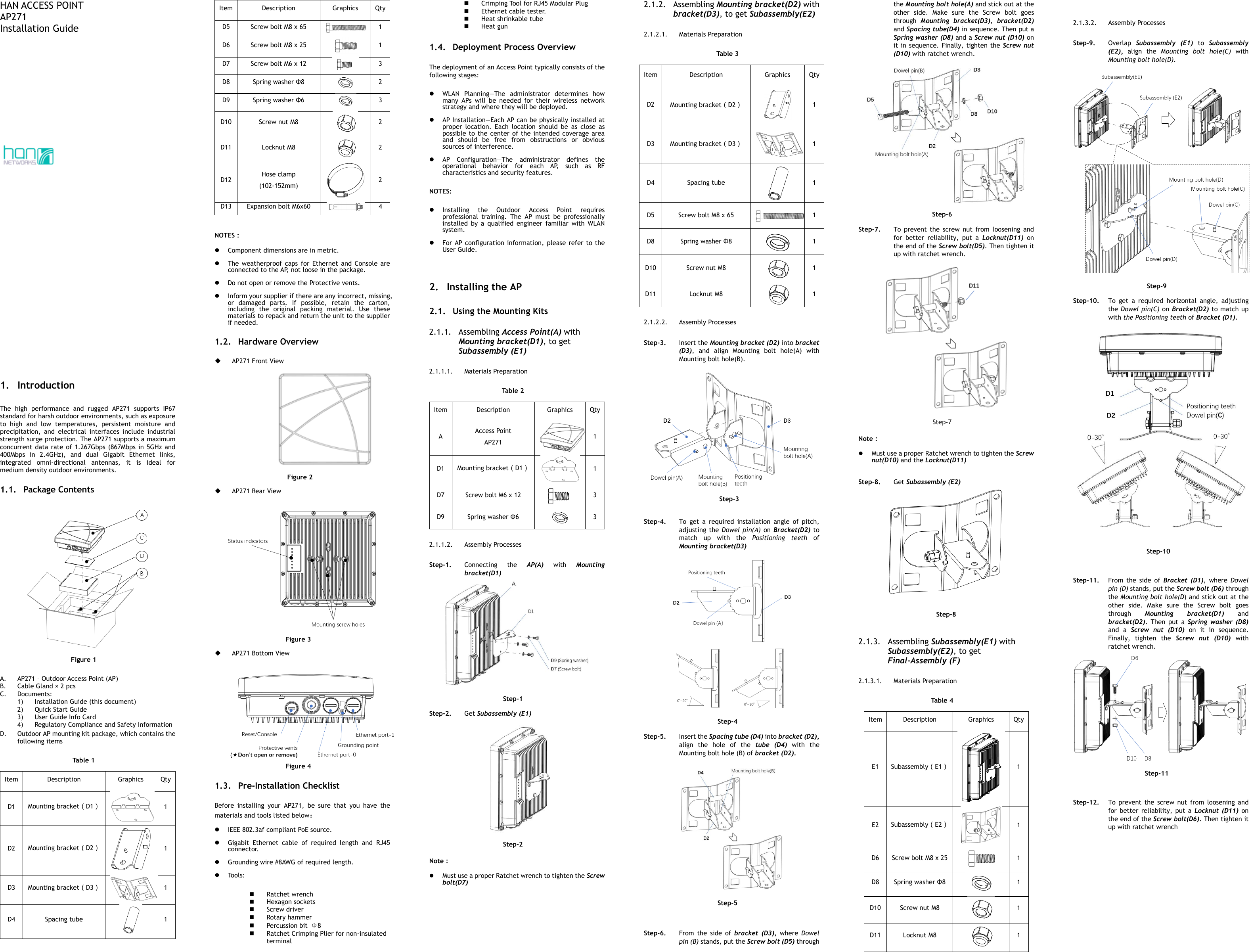
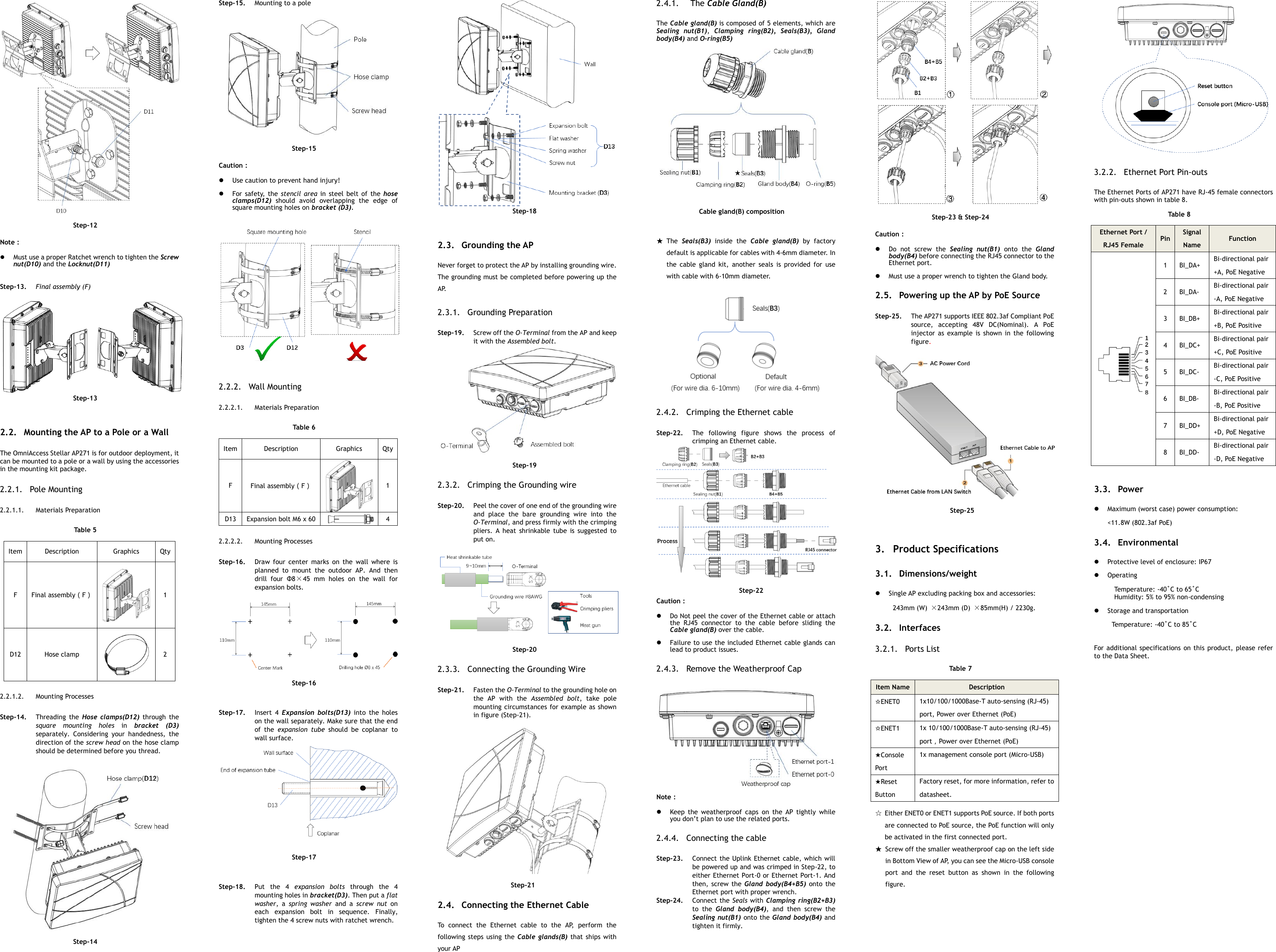
- 3. User Manual(Installation Guide)
- 4. User Manual
- 5. User Manual (Statement)
User Manual(Installation Guide)