HAN Networks AP27X HAN Access Point User Manual Installation Guide
HAN Networks Co., Ltd. HAN Access Point Installation Guide
Contents
- 1. User manual
- 2. User Manual( statement)
- 3. User Manual(Installation Guide)
- 4. User Manual
- 5. User Manual (Statement)
User Manual(Installation Guide)
HAN ACCESS POINT
AP271
Installation Guide
1. Introduction
The high performance and rugged AP271 supports IP67
standard for harsh outdoor environments, such as exposure
to high and low temperatures, persistent moisture and
precipitation, and electrical interfaces include industrial
strength surge protection. The AP271 supports a maximum
concurrent data rate of 1.267Gbps (867Mbps in 5GHz and
400Mbps in 2.4GHz), and dual Gigabit Ethernet links,
integrated omni-directional antennas, it is ideal for
medium density outdoor environments.
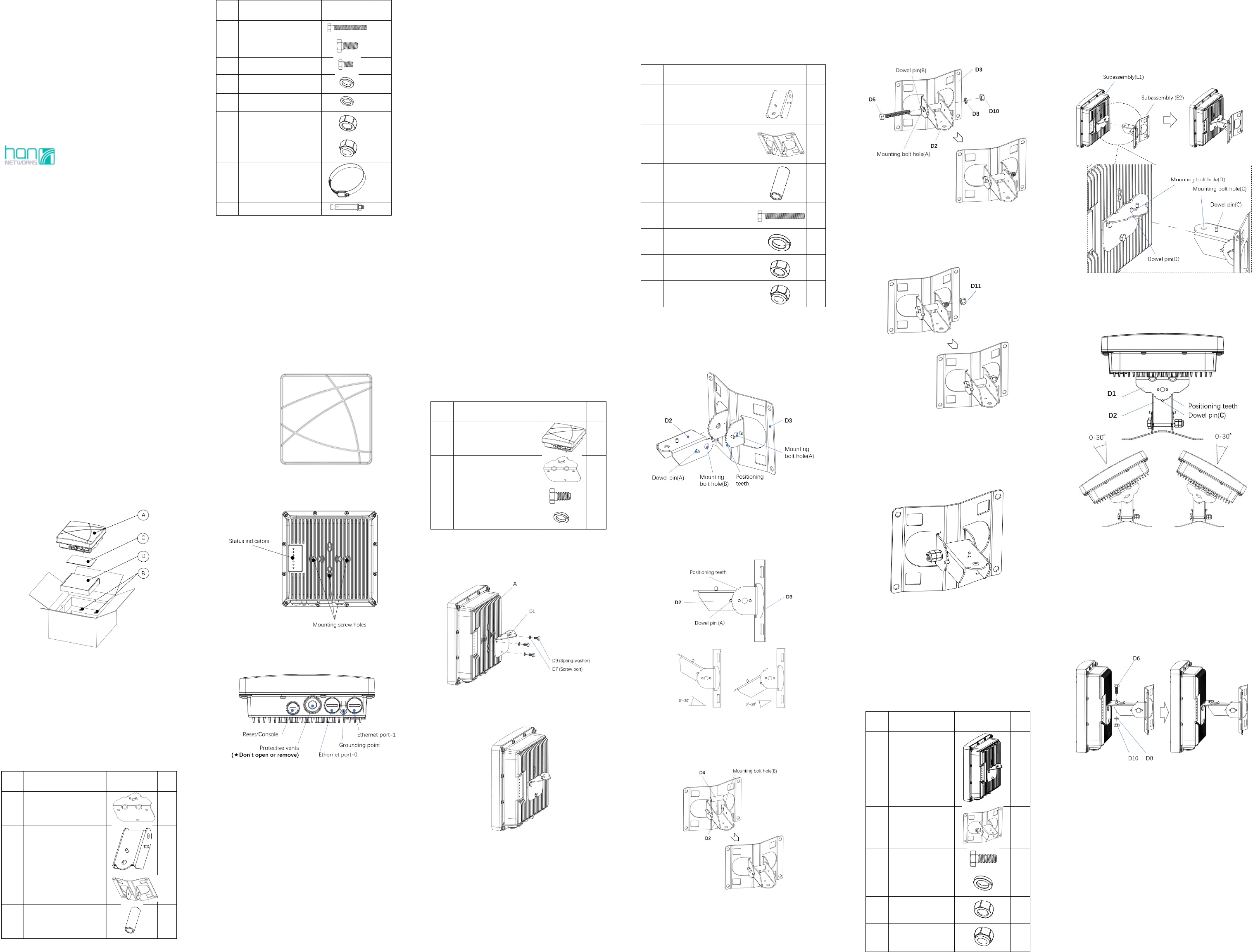
1.1. Package Contents
Figure 1
A. AP271 – Outdoor Access Point (AP)
B. Cable Gland × 2 pcs
C. Documents:
1) Installation Guide (this document)
2) Quick Start Guide
3) User Guide Info Card
4) Regulatory Compliance and Safety Information
D. Outdoor AP mounting kit package, which contains the
following items
Table 1
Item
Description
Graphics
Qty
D1
Mounting bracket(D1)
1
D2
Mounting bracket(D2)
1
D3
Mounting bracket(D3)
1
D4
Spacing tube
1
Item
Description
Graphics
Qty
D5
Screw bolt M8 x 65
1
D6
Screw bolt M8 x 25
1
D7
Screw bolt M6 x 12
3
D8
Spring washer Φ8
2
D9
Spring washer Φ6
3
D10
Screw nut M8
2
D11
Locknut M8
2
D12
Hose clamp
(102-152mm)
2
D13
Expansion bolt M6x60
4
NOTES:
Component dimensions are in metric.
The weatherproof caps for Ethernet and Console are
connected to the AP, not loose in the package.
Do not open or remove the Protective vents.
Inform your supplier if there are any incorrect, missing,
or damaged parts. If possible, retain the carton,
including the original packing material. Use these
materials to repack and return the unit to the supplier
if needed.
1.2. Hardware Overview
AP271 Front View
Figure 2
AP271 Rear View
Figure 3
AP271 Bottom View
Figure 4
1.3. Pre-Installation Checklist
Before installing your AP271, be sure that you have the
materials and tools listed below:
IEEE 802.3af compliant PoE source.
Gigabit Ethernet cable of required length and RJ45
connector.
Grounding wire #8AWG of required length.
Tools:
Ratchet wrench
Hexagon sockets
Screw driver
Rotary hammer
Percussion bit Φ8
Ratchet Crimping Plier for non-insulated
terminal
Crimping Tool for RJ45 Modular Plug
Ethernet cable tester.
Heat shrinkable tube
Heat gun
1.4. Deployment Process Overview
The deployment of an Access Point typically consists of the
following stages:
WLAN Planning—The administrator determines how
many APs will be needed for their wireless network
strategy and where they will be deployed.
AP Installation—Each AP can be physically installed at
proper location. Each location should be as close as
possible to the center of the intended coverage area
and should be free from obstructions or obvious
sources of interference.
AP Configuration—The administrator defines the
operational behavior for each AP, such as RF
characteristics and security features.
NOTES:
Installing the Outdoor Access Point requires
professional training. The AP must be professionally
installed by a qualified engineer familiar with WLAN
system.
For AP configuration information, please refer to the
User Guide.
2. Installing the AP
2.1. Using the Mounting Kits
2.1.1. Assembling Access Point(A) with
Mounting bracket(D1), to get
Subassembly (E1)
2.1.1.1. Materials Preparation
Table 2
Item
Description
Graphics
Qty
A
Access Point
AP271
1
D1
Mounting bracket(D1)
1
D7
Screw bolt M6 x 12
3
D9
Spring washer Φ6
3
2.1.1.2. Assembly Processes
Step-1. Connecting the AP(A) with Mounting
bracket(D1)
Step-1
Step-2. Get Subassembly (E1)
Step-2
Note:
Must use a proper Ratchet wrench to tighten the Screw
bolt(D7)
2.1.2. Assembling Mounting bracket(D2) with
bracket(D3), to get Subassembly(E2)
2.1.2.1. Materials Preparation
Table 3
Item
Description
Graphics
Qty
D2
Mounting bracket(D2)
1
D3
Mounting bracket(D3)
1
D4
Spacing tube
1
D5
Screw bolt M8 x 65
1
D8
Spring washer Φ8
1
D10
Screw nut M8
1
D11
Locknut M8
1
2.1.2.2. Assembly Processes
Step-3. Insert the Mounting bracket (D2) into bracket
(D3), and align Mounting bolt hole(A) with
Mounting bolt hole(B).
Step-3
Step-4. To get a required installation angle of pitch,
adjusting the Dowel pin(A) on Bracket(D2) to
match up with the Positioning teeth of
Mounting bracket(D3)
Step-4
Step-5. Insert the Spacing tube (D4) into bracket (D2),
align the hole of the tube (D4) with the
Mounting bolt hole (B) of bracket (D2).
Step-5
Step-6. From the side of bracket (D3), where Dowel
pin (B) stands, put the Screw bolt (D5) through
the Mounting bolt hole(A) and stick out at the
other side. Make sure the Screw bolt goes
through Mounting bracket(D3), bracket(D2)
and Spacing tube(D4) in sequence. Then put a
Spring washer (D8) and a Screw nut (D10) on
it in sequence. Finally, tighten the Screw nut
(D10) with ratchet wrench.
Step-6
Step-7. To prevent the screw nut from loosening and
for better reliability, put a Locknut(D11) on
the end of the Screw bolt(D5). Then tighten it
up with ratchet wrench.
Step-7
Note:
Must use a proper Ratchet wrench to tighten the Screw
nut(D10) and the Locknut(D11)
Step-8. Get Subassembly (E2)
Step-8
2.1.3. Assembling Subassembly(E1) with
Subassembly(E2), to get
Final-Assembly (F)
2.1.3.1. Materials Preparation
Table 4
Item
Description
Graphics
Qty
E1
Subassembly(E1)
1
E2
Subassembly(E2)
1
D6
Screw bolt M8 x 25
1
D8
Spring washer Φ8
1
D10
Screw nut M8
1
D11
Locknut M8
1
2.1.3.2. Assembly Processes
Step-9. Overlap Subassembly (E1) to Subassembly
(E2), align the Mounting bolt hole(C) with
Mounting bolt hole(D).
Step-9
Step-10. To get a required horizontal angle, adjusting
the Dowel pin(C) on Bracket(D2) to match up
with the Positioning teeth of Bracket (D1).
Step-10
Step-11. From the side of Bracket (D1), where Dowel
pin (D) stands, put the Screw bolt (D6) through
the Mounting bolt hole(D) and stick out at the
other side. Make sure the Screw bolt goes
through Mounting bracket(D1) and
bracket(D2). Then put a Spring washer (D8)
and a Screw nut (D10) on it in sequence.
Finally, tighten the Screw nut (D10) with
ratchet wrench.
Step-11
Step-12. To prevent the screw nut from loosening and
for better reliability, put a Locknut (D11) on
the end of the Screw bolt(D6). Then tighten it
up with ratchet wrench
Step-12
Note:
Must use a proper Ratchet wrench to tighten the Screw
nut(D10) and the Locknut(D11)
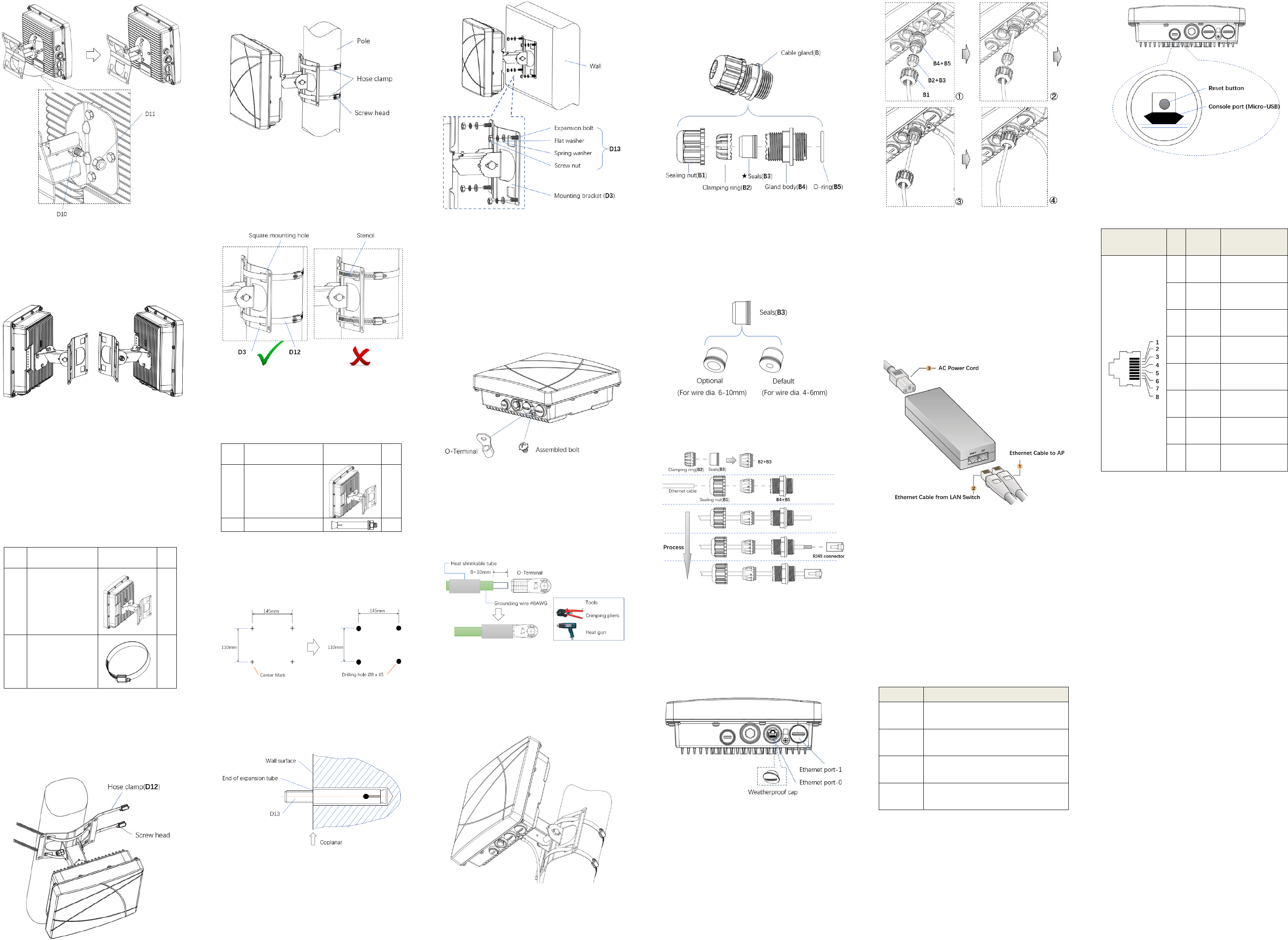
Step-13. Final assembly (F)
Step-13
2.2. Mounting the AP to a Pole or a Wall
The OmniAccess Stellar AP271 is for outdoor deployment, it
can be mounted to a pole or a wall by using the accessories
in the mounting kit package.
2.2.1. Pole Mounting
2.2.1.1. Materials Preparation
Table 5
Item
Description
Graphics
Qty
F
Final assembly(F)
1
D12
Hose clamp
2
2.2.1.2. Mounting Processes
Step-14. Threading the Hose clamps(D12) through the
square mounting holes in bracket (D3)
separately. Considering your handedness, the
direction of the screw head on the hose clamp
should be determined before you thread.
Step-14
Step-15. Mounting to a pole
Step-15
Caution:
Use caution to prevent hand injury!
For safety, the stencil area in steel belt of the hose
clamps(D12) should avoid overlapping the edge of
square mounting holes on bracket (D3).
2.2.2. Wall Mounting
2.2.2.1. Materials Preparation
Table 6
Item
Description
Graphics
Qty
F
Final assembly(F)
1
D13
Expansion bolt M6 x 60
4
2.2.2.2. Mounting Processes
Step-16. Draw four center marks on the wall where is
planned to mount the outdoor AP. And then
drill four Φ8×45 mm holes on the wall for
expansion bolts.
Step-16
Step-17. Insert 4 Expansion bolts(D13) into the holes
on the wall separately. Make sure that the end
of the expansion tube should be coplanar to
wall surface.
Step-17
Step-18. Put the 4 expansion bolts through the 4
mounting holes in bracket(D3). Then put a flat
washer, a spring washer and a screw nut on
each expansion bolt in sequence. Finally,
tighten the 4 screw nuts with ratchet wrench.
Step-18
2.3. Grounding the AP
Never forget to protect the AP by installing grounding wire.
The grounding must be completed before powering up the
AP.
2.3.1. Grounding Preparation
Step-19. Screw off the O-Terminal from the AP and keep
it with the Assembled bolt.
Step-19
2.3.2. Crimping the Grounding wire
Step-20. Peel the cover of one end of the grounding wire
and place the bare grounding wire into the
O-Terminal, and press firmly with the crimping
pliers. A heat shrinkable tube is suggested to
put on.
Step-20
2.3.3. Connecting the Grounding Wire
Step-21. Fasten the O-Terminal to the grounding hole on
the AP with the Assembled bolt, take pole
mounting circumstances for example as shown
in figure (Step-21).
Step-21
2.4. Connecting the Ethernet Cable
To connect the Ethernet cable to the AP, perform the
following steps using the Cable glands(B) that ships with
your AP
2.4.1. The Cable Gland(B)
The Cable gland(B) is composed of 5 elements, which are
Sealing nut(B1), Clamping ring(B2), Seals(B3), Gland
body(B4) and O-ring(B5)
Cable gland(B) composition
★ The Seals(B3) inside the Cable gland(B) by factory
default is applicable for cables with 4-6mm diameter. In
the cable gland kit, another seals is provided for use
with cable with 6-10mm diameter.
2.4.2. Crimping the Ethernet cable
Step-22. The following figure shows the process of
crimping an Ethernet cable.
Step-22
Caution:
Do Not peel the cover of the Ethernet cable or attach
the RJ45 connector to the cable before sliding the
Cable gland(B) over the cable.
Failure to use the included Ethernet cable glands can
lead to product issues.
2.4.3. Remove the Weatherproof Cap
Note:
Keep the weatherproof caps on the AP tightly while
you don’t plan to use the related ports.
2.4.4. Connecting the cable
Step-23. Connect the Uplink Ethernet cable, which will
be powered up and was crimped in Step-22, to
either Ethernet Port-0 or Ethernet Port-1. And
then, screw the Gland body(B4+B5) onto the
Ethernet port with proper wrench.
Step-24. Connect the Seals with Clamping ring(B2+B3)
to the Gland body(B4), and then screw the
Sealing nut(B1) onto the Gland body(B4) and
tighten it firmly.
Step-23 & Step-24
Caution:
Do not screw the Sealing nut(B1) onto the Gland
body(B4) before connecting the RJ45 connector to the
Ethernet port.
Must use a proper wrench to tighten the Gland body.
2.5. Powering up the AP by PoE Source
Step-25. The AP271 supports IEEE 802.3af Compliant PoE
source, accepting 48V DC(Nominal). A PoE
injector as example is shown in the following
figure.
Step-25
3. Product Specifications
3.1. Dimensions/weight
Single AP excluding packing box and accessories:
243mm (W) ×243mm (D) ×85mm(H) / 2230g.
3.2. Interfaces
3.2.1. Ports List
Table 7
Item Name
Description
☆ENET0
1x10/100/1000Base-T auto-sensing (RJ-45)
port, Power over Ethernet (PoE)
☆ENET1
1x 10/100/1000Base-T auto-sensing (RJ-45)
port,Power over Ethernet (PoE)
★Console
Port
1x management console port (Micro-USB)
★Reset
Button
Factory reset, for more information, refer to
datasheet.
☆ Either ENET0 or ENET1 supports PoE source. If both ports
are connected to PoE source, the PoE function will only
be activated in the first connected port.
★ Screw off the smaller weatherproof cap on the left side
in Bottom View of AP, you can see the Micro-USB console
port and the reset button as shown in the following
figure.
3.2.2. Ethernet Port Pin-outs
The Ethernet Ports of AP271 have RJ-45 female connectors
with pin-outs shown in table 8.
Table 8
Ethernet Port /
RJ45 Female
Pin
Signal
Name
Function
1
BI_DA+
Bi-directional pair
+A, PoE Negative
2
BI_DA-
Bi-directional pair
-A, PoE Negative
3
BI_DB+
Bi-directional pair
+B, PoE Positive
4
BI_DC+
Bi-directional pair
+C, PoE Positive
5
BI_DC-
Bi-directional pair
-C, PoE Positive
6
BI_DB-
Bi-directional pair
-B, PoE Positive
7
BI_DD+
Bi-directional pair
+D, PoE Negative
8
BI_DD-
Bi-directional pair
-D, PoE Negative
3.3. Power
Maximum (worst case) power consumption:
<11.8W (802.3af PoE)
3.4. Environmental
Protective level of enclosure: IP67
Operating
Temperature: -40˚C to 65˚C
Humidity: 5% to 95% non-condensing
Storage and transportation
Temperature: -40˚C to 85˚C
For additional specifications on this product, please refer
to the Data Sheet.