HANWAY TECHNOLOGY QV50L VENTILATION FAN User Manual
HANWAY TECHNOLOGY CO., LTD. VENTILATION FAN Users Manual
USERS MANUAL
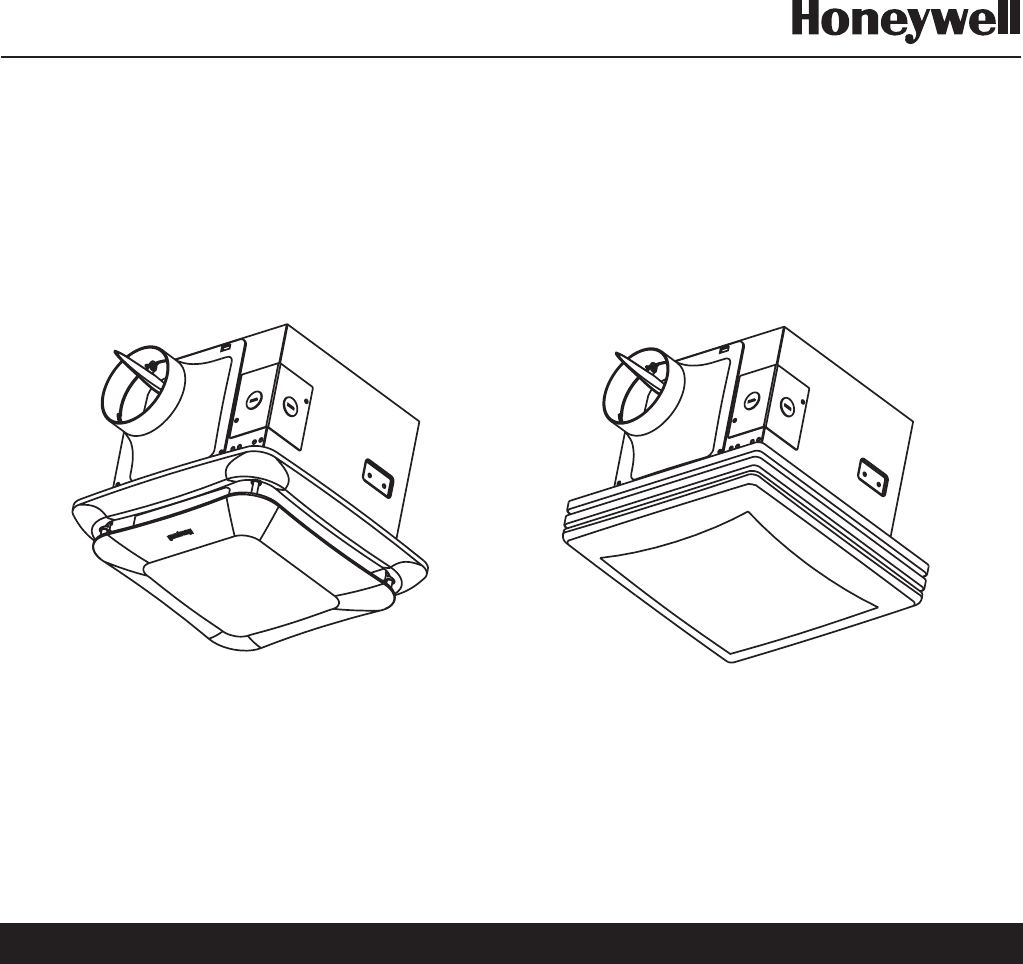
Quiet Ventilation Fan/
Light/Nightlight
READ AND SAVE THESE INSTRUCTIONS
GENERAL SAFETY INFORMATION................................................ ................. ..........2......... ..................
DESCRIPTION...................................................................................................................................3
COMPONENT PARTS.........................................................................................................................3
DIMENSIONS....................................................................................................................................4
SPECIFICATIONS..............................................................................................................................4
INSTALLATION..................................................................................................................................5
CLEANING & MAINTENANCE..............................................................................................................7
TROUBLE SHOOTING GUIDE.............................................................................................................7
SERVICE PARTS................................................................................................................................8
WARRANTY......................................................................................................................................9
Models QV50L/QV80L/QV110L/QV150L
INSTALLATION INSTRUCTIONS
The Honeywell trademark is used under license from Honeywell Intellectual Properties Inc.
by Lonon Industry Company, Ltd.
Honeywell International Inc. makes no representations or warranties with respect to this product.
TABLE OF CONTENTS
Quiet Decorative Ventilation
Fan/Light/Nightlight
Models QDV70L/QDV80L/QDV90L/
QDV110L/QDV130L/QDV150L
Page 2
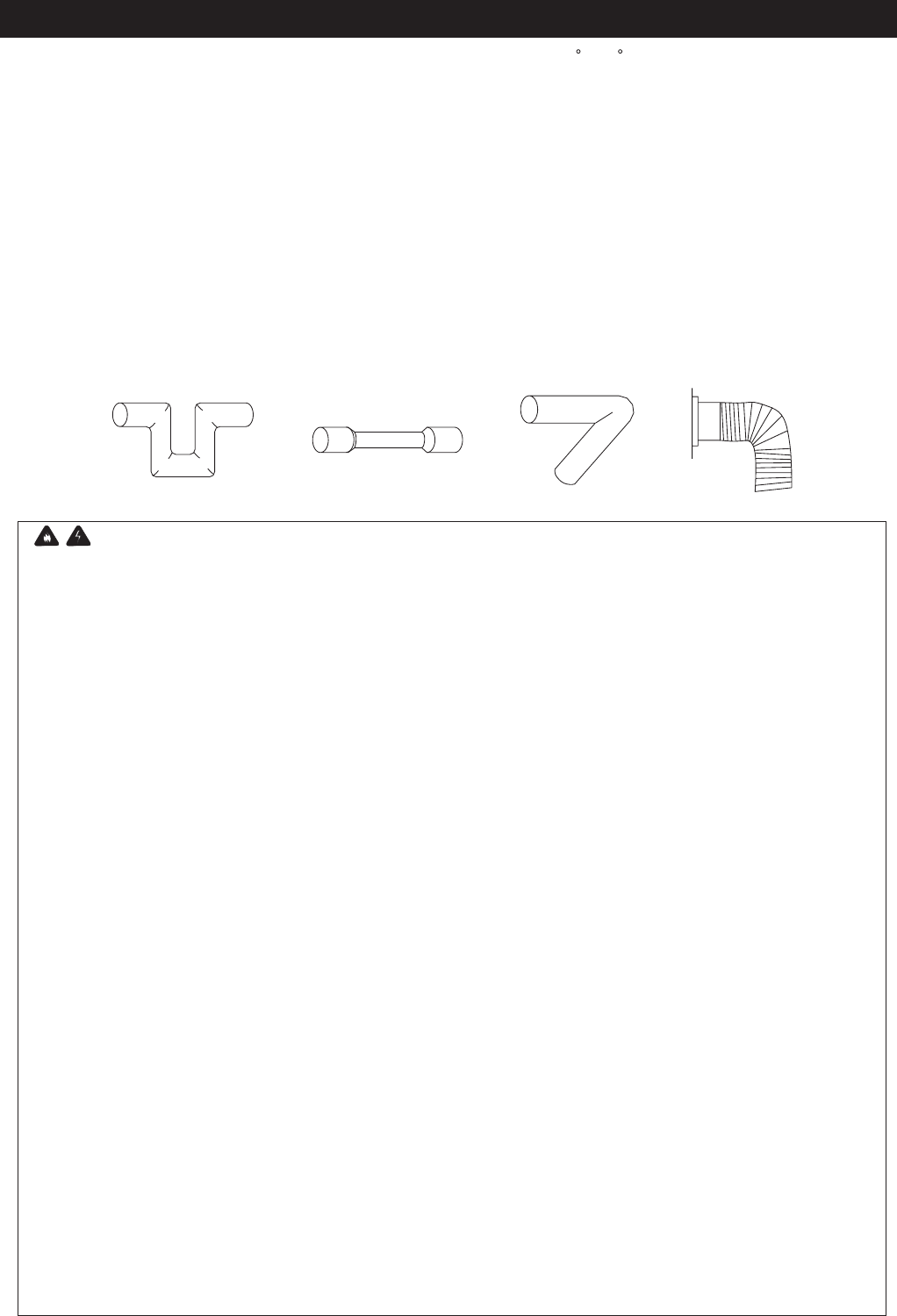
Fig.A
WARNING:
TO REDUCE THE RISK OF FIRE, ELECTRIC SHOCK, OR INJURY TO PERSONS, OBSERVE THE
FOLLOWING:
1. Use this unit only in the manner intended by . If you have questions, please contact
at the address or telephone number listed in the warranty.
2. Before servicing or cleaning unit, switch the power off at service panel and lock the service
disconnecting means to prevent power from being switched on accidentally. When the service
disconnecting means cannot be locked, securely fasten a prominent warning device, such as a tag, to
the service panel.
3. Installation work and electrical wiring must be done by a qualified person(s) in accordance with all
applicable codes and standards, including fire-rated construction codes and standards.
Lonon USA, LLC
Lonon USA, LLC
4. Sufficient air is needed for proper combustion and exhausting of gases through the flue (chimney) of fuel
burning equipment to prevent back drafting. Follow the heating equipment manufacturer's guideline and
safety standards, such as those published by the National Fire Protection Association (NFPA) and the
American Society for Heating, Refrigeration and Air Conditioning Engineers (ASHRAE), and the local
code authorities.
5. When cutting or drilling into wall or ceiling, make sure not to damage electrical wiring and other hidden
utilities.
6. Ducted fans must always be vented to the outdoors.
7. NEVER place a switch where it can be reached from a tub or shower.
8. Please note that solid state controls may cause harmonic distortion that can cause motor humming
noise.
9. To reduce the risk of fire or electric shock, do not use this fan with any solid-state speed control device.
10. Not to be in a ceiling thermally insulated to a value greater than R40.
11. Fluorescent models only: Do not use a dimmer switch to control the light of this unit.
12. Motor and grille assembly must be installed with housing assembly that are marked (on their cartons) to
indicate the suitability with this model. Other housing assembly cannot be substituted.
13. To reduce the risk of fire use only these 18 watt fluorescent lamps and 4 watt maximum type C
incandescent lamp nightlight.
1. Do not install this ventilating fan where air temperature may exceed 104 F (40 C).
2. Make sure that the electric service supply voltage is 120V, 60Hz.
3. Follow all local electrical and safety codes, as well as the National Electrical Code (NEC) and the Occupation
Safety and Health Act (OSHA).
4. Always disconnect the power source before working on or near the fan, motor or junction box or light fixture.
5. Protect the power cord from sharp edges, oil, grease, hot surfaces, chemicals or other objects.
6. Do not kink the power cord.
7. This unit is approved for use over a bathtub or shower when installed in a GFCI protected branch circuit.
8. This unit must be grounded.
9. This unit is U.L. Listed. Type I.C. Inherently protected.
10. These models are UL listed for tub and shower enclosures.
11. Provide suction parts with proper ventilation.
12. Do not install the unit where ducts are configured as shown in Fig.A.
GENERAL SAFETY INFORMATION
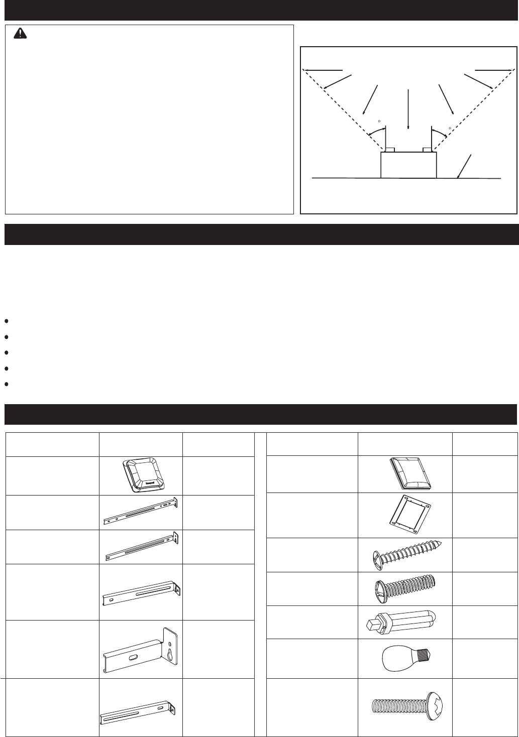
1. For general ventilating use only.
2. This product is designed for ceiling installation only. This
product is designed for installation in ceilings up to a 12/12
pitch. Ductwork must point up. DO NOT MOUNT THIS
PRODUCT ON A WALL.
3. The light fixture assembly must be mounted to the fan
housing assembly included with this product. Do not mount
the fight fixture assembly to a wiring outlet box.
4. To avoid motor bearing damage and noisy and / or
unbalanced impellers, keep drywall spray, construction
dust, etc. off power unit.
5. Please read specification label on product for further
information and requirements.
6. Not for use in cooking area (Fig. B).
Do not use to exhaust
hazardous or explosive materials and vapors.
CAUTION:
Fig.B
(Cooking area)
Do not install above or
inside this area
Cooking
equipment
Floor
45
45
Page 3
DESCRIPTION
Thank you for selecting this high quantity Honeywell ventilation fan. Honeywell ventilation fans were designed with
your comfort in mind. With many different features, Honeywell fans fit your needs whether your bathroom is big or
small, needs a light, no light or even a nightlight, Honeywell fans have the features you need.
Honeywell ceiling mounted ventilation fans use a high-capacity sirocco fan driven by a capacitor motor. The sirocco
fan reduces the noise level.
Honeywell ventilation fans incorporate a thermal cut off for safety.
The grille unit can be quickly detached from the main unit for cleaning.
A damper for preventing air backdraft is incorporated into every fan.
The light unit is an energy efficient lighting device which uses two 18W compact fluorescent lamps.
The motor is designed to have an extended service life with reduced energy consumption.
GENERAL SAFETY INFORMATION ( Continued )
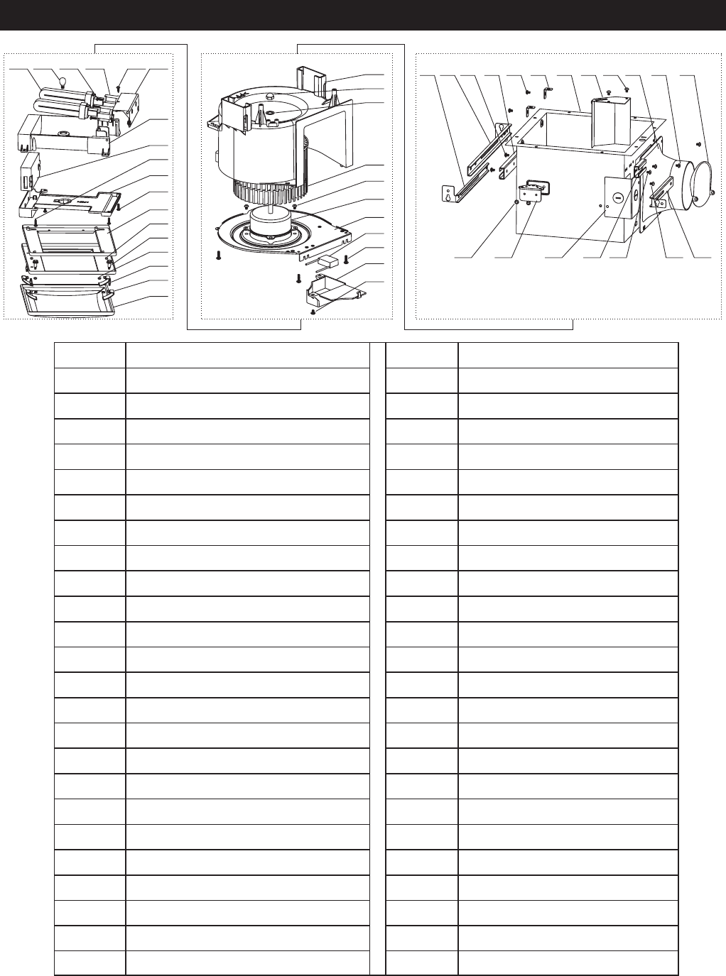
COMPONENT PARTS
18 W
fluorescent lamp
2
Part name
Picture
Part name
Picture
Quantity Quantity
Grille 1
8
2
1
Suspension
bracket A
(12.6inches/320mm)
Suspension
bracket B
(9.5inches/240mm)
Suspension
bracket C
(6.3inches/160mm)
QV110L/150L
not supplied
Suspension
bracket D
(2.95inches/75mm)
QV110L/150L
not supplied
Suspension
bracket E
(5.3inches/135mm)
QV50L/80L
not supplied
1
1
1
1
Screw A
ST4X30
Screw B
M4X10
4 W
Night lamp
Glass sub-1
( glass grille )
Screw E
M5X20
Grille sub-2
1
4
1
1
QDV70L 120V/60Hz
21.0
36.0 4.0 70 <0.3 4
QDV80L 120V/60Hz 23.0 36.0 4.0 80 0.5 4
QDV90L 120V/60Hz 24.0 36.0 4.0 90 0.5 4
QDV110L 120V/60Hz
32.0
36.0 4.0 110 0.3 6
QDV130L 120V/60Hz 35.0 36.0 4.0 130 0.6 6
QDV150L 120V/60Hz 41.0 36.0 4.0 150 1.0 6
15.32
15.32
15.32
19.29
19.29
19.29
Page 4
SPECIFICATIONS
*At 0.0" Static pressure (Pa).
Specifications are based on HVI standard.
Power consumption*(W)
QV50L 120V/60Hz
17.0
36.0 4.0 50 <0.3 4
QV80L 120V/60Hz 21.0 36.0 4.0 80 0.3 4
QV110L 120V/60Hz
33.0
36.0 4.0 110 0.9 6
QV150L 120V/60Hz 39.0 36.0 4.0 150 0.9 6
Duct
Diameter
(inch)
Weight
(lb.)
Noise
(sone)
Air
Movement
0.1" WG
(CFM)
Light Unit
Light Night Light
Fan
Unit
Power
Supply
Model
No.
9.9
9.9
12.5
12.5
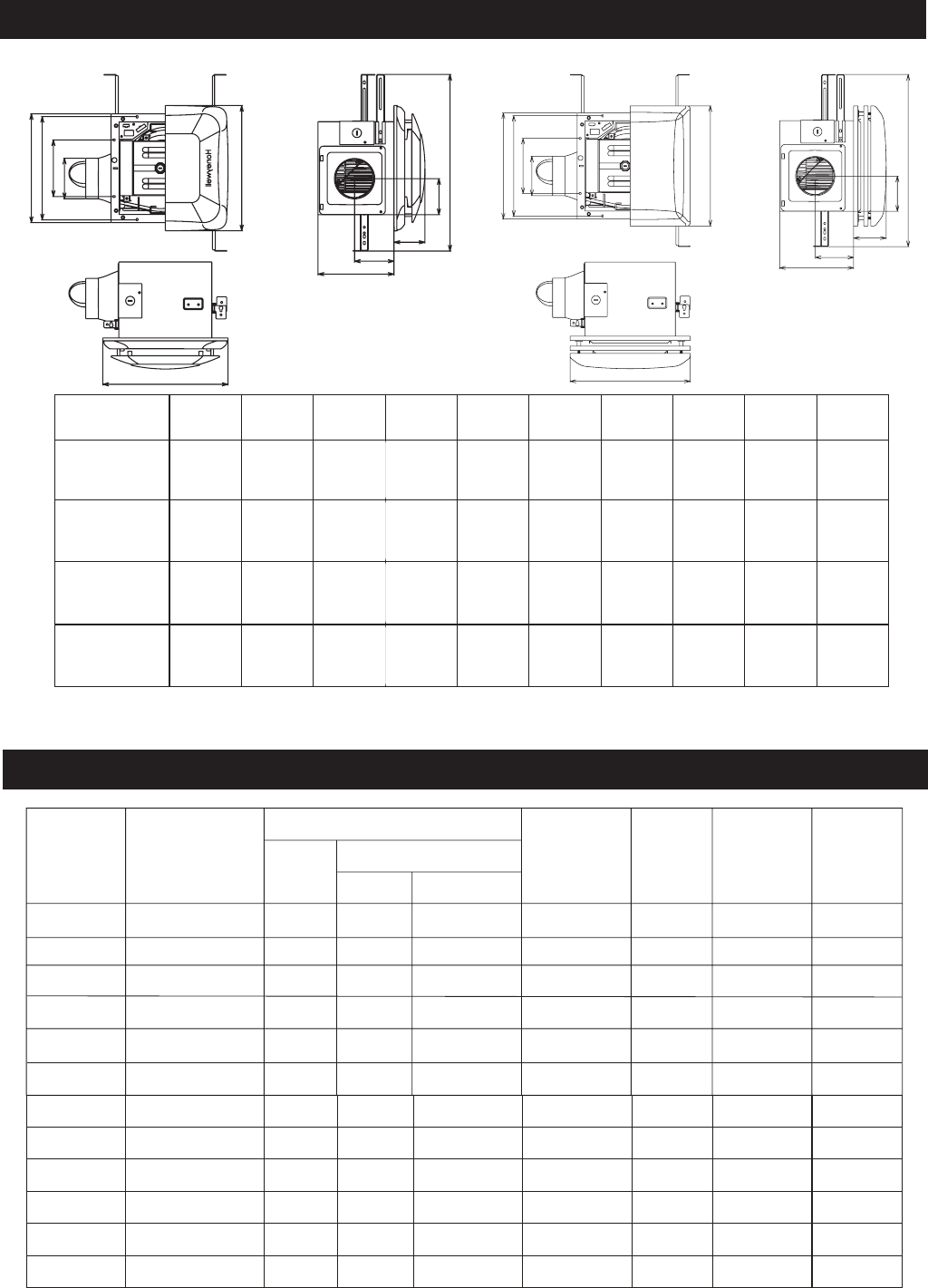
254-584mm
G
H
I
J
B
A
C
D
E
F
DIMENSIONS
C
D
E
A
B
F
G
H
I
J
254-584mm
Model No. ABCDE
QV50L
QV80L
QV90L
QV110L
QV130L
QV150L
10 9/16 10 5 1/2 4 12 3/16
"""" "
FG
3 1/2 ½
11 7/16 6 3/8 613 3/4¾
12 5/16 """"
"4 5/16"
"
12 3/16"3 1/8
3 1/8
HI
4 1/8
4 1/8
"
"
""
J
7 7/8
7 7/8 ½
"
"
13 3/4¾
"
QDV70L
QDV80L
QDV90L
QDV110L
QDV130L
QDV150L
10 9/16 10 5 1/2 4 12 3/16
"""" " 3 1/2 ½
11 7/16 6 3/8 613 3/4¾
12 5/16 """"
"4 5/16"
"
12 3/16"3 1/8
3 1/8
4 1/8
4 1/8
"
"
""
7 7/8
7 7/8 ½
"
"
13 3/4¾
"
QV90L 120V/60Hz 24.0 36.0 4.0 90 0.5 4
9.9
QV130L 120V/60Hz 36.0 36.0 4.0 130 0.8 6
12.5
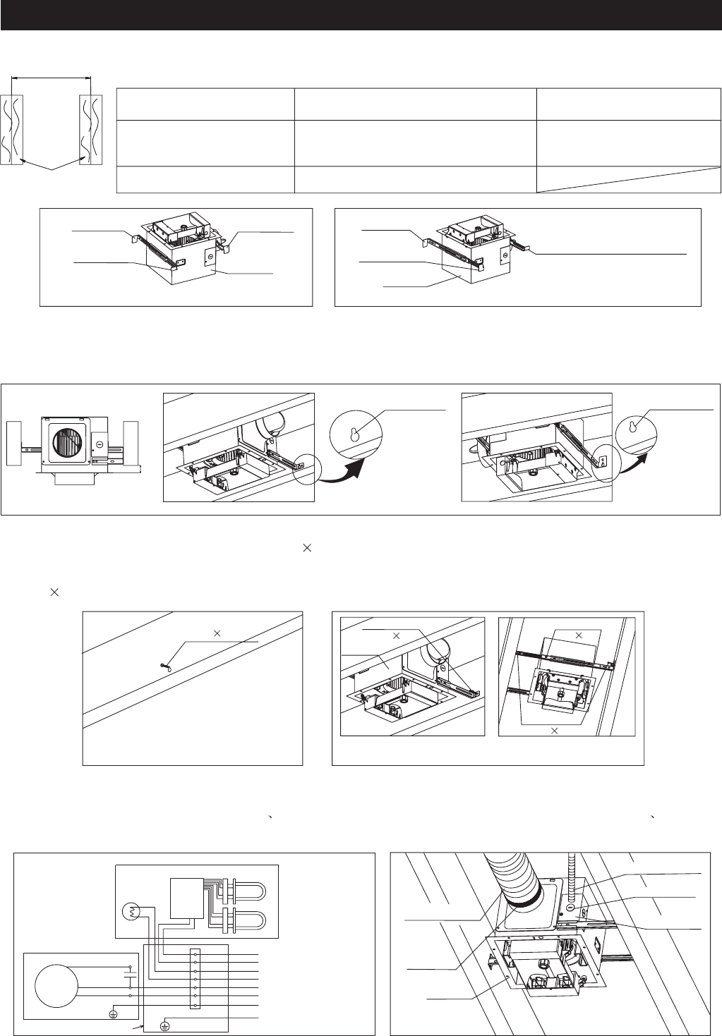
Wiring Diagram
Light unit
Electric
Ballast
Night lamp
18W Lamp
18W Lamp
Fan unit
Motor
Condenser
Blue
White
Black
Earth Ground
Wiring box
Black
White
Black
White
White
Black
Green
Green terminal
Earth Ground
Black
White
Black
White
White
Black
Green
Earth Ground
Earth Ground
Power supply(120V~60Hz)
Power supply(120V~60Hz)
Power supply(120V~60Hz)
S1. Select the suspension bracket and insert them into the housing according to the table-1 as below.
Page 5
S4. Remove the wiring cover and the knockout hole, make the electrical cable through the knockout hole, and
connect the house power wires to wires of the product according to the wiring diagram. Then secure the circular
duct ( 4 inches duct for QV50L/80L/90L QDV70L/80L/90L and 6 inches duct for QV110L//130L/150L
QDV110L/130L/150L ) with duct tape (Fig.6).
S2. Choose the location for your fan in the ceiling. For best possible performance, use the shortest possible duct run
and minimum number of elbows. Mark the keyhole slot on both suspension brackets and keep the distance B for
the thickness of the ceiling board (Fig.3).
S3. Set housing aside and drive the screw A (ST4 30) partially into joists at the top of both keyhole marks (Fig.4).
Hang housing from the screw A and drive the screw A tight. To ensure a noise-free mount, drive other screw A
through the round holes of suspension brackets. Secure the suspension brackets to the housing by screw B
(M4 10) (Fig.5).
Circular duct
Duct tape
Wiring cover
Knockout hole
Housing
Fig.6
Electrical cable
INSTALLATION ( The housing is in the middle of joists )
Fig.1
Suspension
Bracket B
Suspension
Bracket C
Suspension
Bracket D
Housing
Fig.2
Suspension
Bracket A
Suspension
Bracket B
Suspension Bracket C
(for models QV50L/80L/90L)
(for models QDV70L/80L/90L)
Suspension Bracket E
(for models QV110L/130L/150L)
(for models QDV110l/130l/150l)
Housing
Fig.5
4-Screw A
(ST4 30)
2-Screw B
(M4 10)
2-Screw A
(ST4 30)
Housing
Screw A
(ST4 30)
Fig.4
Joists
A
table-1
The joists center distance A Insert the suspension bracket method Remark
16 inches
19.2 inches or 24 inches
Refer to Fig.1 insert
Refer to Fig.2 insert
This method is not fit the
products QV110L/130L/150L
QDV110L/130L/150L
Keyhole slot
B
Fig.3
Keyhole slot
INSTALLATION ( The housing is in the middle of joists )( Continued )
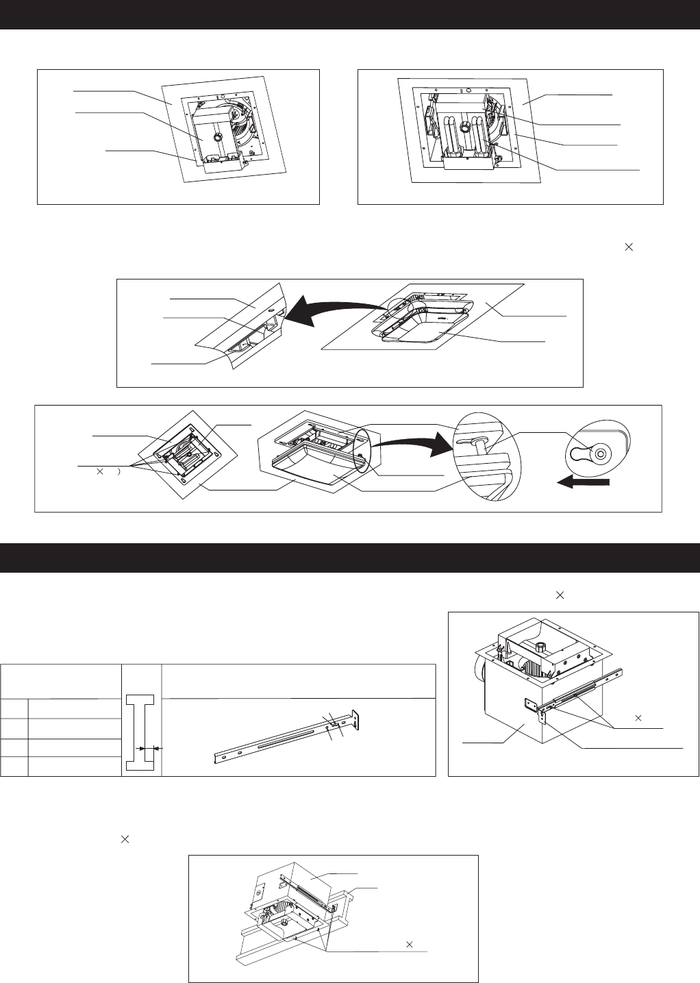
S6. For models QV50L/80L/90L/110L/130L/150L, insert the grille springs into the slots of the casing and mount the
grille unit. Finish the installation work (Fig.9.1).
For models QDV70L/80L/90L/110L/130L/150L, secure the grille sub-2 to the housing by screw E (M5 20). Insert
the sliding shaft to the grille sub-2, then turn the grille sub-1 along the arrow mark and finish the installation work
(Fig.9.2).
S2. Choose the location for your fan in the ceiling. For best possible performance, use the shortest possible duct run
and minimum number of elbows. Lock the flange of the product and the suspension bracket A tightly to the I-joist
by screw A (ST4 30) (Fig.11).
S1. Insert the suspension bracket A into the housing and secure it to housing by screw B (M4 10) according to the
distance C in table-2 (Fig.10).
S3. Please follow S4 to S6 of installation, ( page 5, page 6 ), to finish the installation work.
INSTALLATION ( I-joists mounting )
Table-2
C1
C2
C3
C4
4 kinds of I-joist
inches(mm)
C1 9/16 (14.3)
C
C2 11/16 (17.5)
C3 31/32 (24.6)
C4 1 17//32 (38.9)
The suspension bracket A can accommodate
different kinds of I-joist.
Page 6
S5. Finish the ceiling work, ceiling hole should be kept for the product (Fig.7). Then insert the 18 watt fluorescent
lamps into the lighting unit and screw the 4 watt nightlight into the lighting unit (Fig.8).
Fig.9.1
Ceiling board
Grille unit
Ceiling board
Grille spring
Slot
Fig.8
Ceiling board
Fluorescent Lamp
Housing
Lighting Housing
Fig.7
Ceiling board
Lighting unit
Housing
Fig.10
Housing
2-Screw B
(M4 10)
Suspension bracket A
Fig.11
Housing
I-joist
4-Screw A(ST4 30)
Fig.9.2
Grille sub-2
Housing
4-Screw E
(M5 20
Ceiling board Grille sub-1
Grille sub-2
Sliding shaft
Sliding shaft
Turning way of sliding shaft
Page 7
CLEANING & MAINTENANCE
WARNING
CAUTION
CLEANING
MAINTENANCE
REPLACEMENT OF LAMP
1. Disconnect power source before working on unit.
2. The lamp's glass is fragile. Please handle with care. To remove lamp, grasp at base and move back and force to
loosen.
3. Do not pull hard on the lamp or you may break the glass.
4. 4W night lamp has threaded base. Remove by turning counterclockwise.
1. Never use petrol, benzene, thinner or any other such chemicals for cleaning the ventilating fan.
2. Do not allow water to enter motor.
3. Metal and electrical parts should never be immersed in water.
4. Do not immerse resin parts in water over 140 F (60 C).
5. Allow bulb and lamps to cool before replacing.
Squeeze grill springs and pull grille down carefully. Use non-abrasive kitchen detergent wash, and wipe grille dry with
new cloth.
Remove bulbs, if necessary. Remove dust and dirt on fan body using vacuum cleaner. Using a cloth dampened with
mild dish soap, remove any dirt from fan body. Wipe dry with new cloth.
Replace bulbs and grille.
The motor is permanently lubricated and never needs oiling. If the motor bearings are making excessive or unusual
noises, replace the motor with the exact service motor. You must replace the impeller at the same time.
Remove grille. Disconnect the connectors of light unit from fan unit. Change the 18W fluorescent bulb or the 4W
incandescent lamp, connect the connectors and replace the grille.
TROUBLE SHOOTING GUIDE
Problem:
Solution:
Problem:
Solution:
Problem:
Solution:
Fan does not come on.
Honeywell ventilation fans are extremely quiet. To confirm that the fan is running, place your hand near the vents
to feel the air movement.
Turn power on, replace fuse, or reset breaker.
Check all plug connections to be sure they are secure.
Check the wiring to make sure it matches the wiring diagram.
Light does not come on.
Replace the light bulb with a new bulb.
Turn power on, replace fuse, or reset breaker.
Check all plug connections to be sure they are secure.
Check the wiring to make sure it matches the wiring diagram.
Fan is noisy.
Check and tighten all fasteners.
Check the flapper to make sure it moves freely.
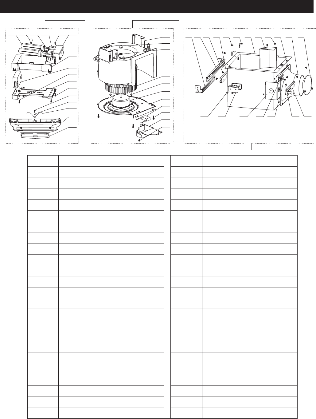
SERVICE PARTS (FOR QV50L/80L/90L/110L/130L/150L)
Page 8
20
21
22
23
24
25
26
27
28
29
30
78 4569101112 3 2
13
1
14 15 16 17 18 19
363531 32 33 34
37
38
39
40
41
42
43
44
45
46
No. Part name No. Part name
Damper
Condenser
Adaptor setting screw
Wiring box setting screw
Wiring box
Motor setting screw
Motor
Motor support
28
1
2
3
4
5
6
24
25
26
27
29
Adaptor
Casing setting screw
Condenser box
Housing
Ballast box support
Lampholder setting screw
Ballast box support setting screw
Bracket cover A setting screw
Suspension bracket A
Condenser box setting screw
Fluorescent lamp
Night lamp
34
7
8
9
10
11
12
30
31
32
33
35
Bracket cover A
Lampholder
Lampholder cover setting screw
Suspension bracket B
Casing support setting screw
Ballast box cover setting screw A
Casing support
Bracket cover B
Lampholder cover
Ballast box
Ballast
13
14
15
16
36
37
38
39
Wiring cover
Bracket cover B setting screw
Spring hook
Wiring cover setting screw
Casing
Blower wheel setting nut
Ballast box cover
Ballast box cover setting screw B
Spring hook setting screw
44
17
18
19
20
21
22
40
41
42
43
45
Suspension bracket C
Grille spring
Grille
Blower wheel setting washer
Blower wheel Lamper cover
23 46
SERVICE PARTS (FOR QDV70L/80L/90L/110L/130L/150L)
*These instructions may be printed in English ("the English version") and one or more other languages ("other versions"), in
which case the English version shall prevail if there is any inconsistency between the English version and any one or more of
the other versions.
20
21
22
23
24
25
26
27
28
29
30
78 4569101112 3 2
13
1
14 15 16 17 18 19
363531 32 33 34
37
38
39
40
41
42
43
44
45
48
46
47
No. Part name No. Part name
Damper
Casing setting screw
Adaptor setting screw
Wiring box setting screw
Wiring box
Motor
Motor support
Condenser
29
1
2
3
4
5
6
25
26
27
28
30
Adaptor
Condenser box
Condenser box setting screw
Housing
Ballast box support
Lampholder
Ballast box support setting screw
Bracket cover A setting screw
Suspension bracket A
Fluorescent lamp
Night lamp
Lampholder setting screw
35
7
8
9
10
11
12
31
32
33
34
36
Bracket cover A
Lampholder cover setting screw
Lampholder cover
Suspension bracket B
Casing support setting screw
Ballast box cover
Casing support
Bracket cover B
Ballast box
Ballast
Ballast box cover setting screw A
13
14
15
16
37
38
39
40
Wiring cover
Bracket cover B setting screw
Sliding shaft
Wiring cover setting screw
Casing
Blower wheel setting nut
Ballast box cover setting screw B
Grille sub-2
Nut (M5)
45
17
18
19
20
21
22
41
42
43
44
46
Suspension bracket C
Nut (M5)
Bolt
Blower wheel setting washer
Blower wheel Glass grille hook
23 47
Motor setting screw Glass grille
24 48
Page 9
Page 10
WARRANTY
LONON USA, LLC
LIMITED WARRANTY
Product Name: Model Number:
Date of purchase: Dealer:
Date of installation: Builder/ Installer:
Warranty Period (from date of original purchase) ("Warranty Period"): Five (5) years for the motor; One (1) year for
other parts.
LIMITED WARRANTY.
THIS WARRANTY
SHALL BE VALID ONLY IF THE PRODUCT IS PURCHASED AND INSTALLED IN THE UNITED STATES.
Lonon USA, LLC ("LONON") gives this limited warranty ("this Warranty") to the original
purchaser of the Product ("Buyer"), subject to the following terms: LONON warrants that the Product will be free
from original defects in materials and workmanship for the Warranty Period, PROVIDED (i) that the Product has been
properly stored, installed, serviced, maintained and operated; (ii) that the Product has not been altered or repaired in
any way which, in LONON's reasonable judgment, will affect its performance or reliability; and (iii) that the Product
has not been improperly installed or subjected to misuse, negligence, or accident, or incorrectly used in combination
with other articles. Save where provided otherwise in this Warranty, Buyer assumes all risks and liability for results
of use of the Product. Where applicable, warranties on purchased parts are limited to the terms of the warranties
extended by LONON's supplier(s). Without prejudice to the limitations and exclusions below,
WARRANTY SERVICE. All claims under this Warranty shall be made in writing and delivered to LONON at the
address set out below within 15 days after discovery of the defect and prior to the expiration of the Warranty Period.
Buyer shall be barred from any remedy if Buyer fails to make such claim within such period. Within 30 days after
receipt of a timely claim, LONON shall have the option either to inspect the Product while in Buyer's possession or to
request Buyer to return the Product to LONON at Buyer's expense for inspection by LONON. Subject to the terms of
this Warranty, LONON will, during the Warranty Period, at its option replace or repair, free of charge, the Product or
part thereof which LONON determines is defective under normal use and maintenance.
This Warranty does not cover and LONON is not responsible for : (i) normal maintenance and service; (ii) any Product
which has been subjected to misuse, improper maintenance or modification, neglect, electrical current fluctuations,
negligence, accident, improper or faulty operation or installation or installation contrary to the installation
instructions, use of parts or supplies other than LONON's that cause damage to the Product, defacement, alteration,
or removal of a product serial number; (iii) the cost of removal of the defective Product or part, damages due to
removal, or any expenses incurred in shipping the defective Product or part to or from LONON's service centre, or
the installation of the repaired or replacement product or part; (iv) any glass component, light bulb, fluorescent lamp,
starter, tube, filter, duct, roof cap, wall cap or other ducting accessories even where the Product is equipped with any
of the same.
Subject to the above warranty, to the maximum extent permitted by applicable law: (i) LONON and its suppliers
provide the Product as is and hereby disclaim all other warranties and conditions whether express implied or
statutory, including without limitation implied warranties or conditions of merchantability and of fitness for a
particular purpose, and any responsibility for any loss of revenues or profits, inconvenience, expense for substitute
equipment or service, storage charges, or loss or corruption of data; (ii) implied warranties, when applicable, shall
commence upon the same date as the express warranty provided above, and shall, except for warranties of title,
extend only for the duration of the express warranty above; (iii) LONON assumes no liability on account of any
recommendations, opinions or advise as to the choice, installation or use of the Product, and any such
recommendations, opinions or advice given are accepted at the original purchaser's own risk and shall not
constitute any warranty or guarantee concerning any matter; (iv) in no event shall LONON and its suppliers be liable
for any special, incidental, punitive, indirect, or consequential damages whatsoever arising out of or in any way
related to the use of or inability to use the Product for whatever reason and based on whatever cause of action;

W
ARRANTY
(
Continued
)
(v)
the
entir
e
liability
of
LONON
and
its
suppliers
in relation
to
the
manufactur
e
and
supply
of
the
Pr
oduct
is
limited
to
the
amount
actually
paid
by
the
original
pur
chaser
for
the
Pr
oduct.
Damages
ar
e
limited
to
the
pur
chase
price
of
the
Pr
oduct.
This
W
arranty
gives
the
Buyer
specific
legal
rights.
Some
states
do
not
allow
limitation
on
how
long
an
implied
warranty lasts,
or
exclusion
of
or
limitation
on
incidental
or
consequential
damages.
The
extent
to
which
the
above
limitations
and
exclusions
ar
e
valid may
vary
from
state
to
state.
No
agent,
dealer
, employee
or
other
person
is authorized
to
give
any
other
warranties
or
assume
any
other
liability
on
LONON's
behalf in
connection
with
the
Pr
oduct
except
in
writing
signed
by
an
authorized
of
ficer
of
LONON.
Notwithstanding
any
past
practice
or
dealings
or
any
custom
of
the
trade,
the
supply
of
the
Pr
oduct
does
not
include
the
pr
ovision
of
any
technical
advice
or
system
design,
which
may
be
pr
ovided
at
LONON's
sole
option
and
subject
to
additional
charges.
This
W
arranty may
be
printed
in
English
("the
English
version")
and
one
or
mor
e
other
languages
("other
versions"),
in
which
case
the
English
version
shall
pr
evail
if
ther
e
is
any
inconsistency
between
the
English
version
and
any
one
or
mor
e
of
the
other
ve
rsions.
FOR
ASSISTANCE:
PLEASE
CONT
ACT
Lonon
USA,
LLC
Customer
Service
Centr
e:
4320 Winfield Road, Suite 200
Warrenville,
IL
60555
Opening hours:
Mon.
-
Fri.
(except
public
holidays):
8:00 am
to
3:30
pm
T
oll
fr
ee
service
hotline:
1-888-566-6687
IMPORTANT
:
The original invoice for
the
purchase of
the
Product
together
with this
warranty
car
d
must
be
pr
esented in
or
der
to quality
for service under this Warranty.
FCC NOTE
The manufacture is not responsible for any radio or TV interference caused by unauthorized modifications to this
equipment. Such modifications could void the user’s authority to operate the equipment. This product may cause
interference to radio equipment and should not be installed near maritime safety communications equipment or other
critical navigation or communication equipment operating between 0.45-30MHz.
Page
11
Version:A Revision Data: 12/14/2005
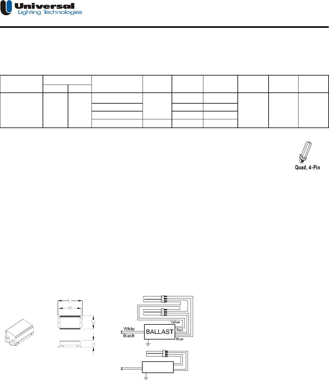
Description: Electronic ballast for compact fluorescent Lamp (2)T4quad 4pin 13W or (2) T5 linear 13W/14W/28W
• Line Voltage : 120Vac, 60Hz • Rapid Start
• Series Lamp Connection WS-3
Input Power Crest
Volts Freq-Hz Watts* Factor Factor
29
30
30
130
*ANSI measured wattage,25℃ ambient,benchtop,lamps base up ; Enclosed fixture, wattage may change depending on fixture type.
Application and Performance Specification Information Subject to Change without Notification.
Performance: Safety:
• Meets ANSI Standard C82.11-1993 • No PCB's
• Meets ANSI Standard C62.41-1991 • UL listed (Class P)
• Meets UL 935 • UL # 221323
• Meets FCC Part 18 (Class B) for EMI
• Operating Frequency Range: 45-55 kHz
• Abnormal Protection Circuit
• End of lamp life protection Circuit
• Auto-Reset Shutdown Circuit
- lamp(s) should be replaced at end of lamp life
- Lamp relights upon insertion in socket
Application: Physical Parameters
• Minimum Starting Temperature: 5° F (-15° C) Case: CM-31(#90-5B)
• Maximum Ambient Temperature: 122° F(50° C) Overall Length(L): 3.86"(99mm)
• Maximum Case Temperature (@ tc): 158° F(70° C) Width(W): 2"(52mm)
• Sound Rated: A Mounting(M): 3.5"(90mm)
Height(H): 1.00"(25.4mm)
Weight: 0.55bs(0.25kg)
Qty/Carton: 30
Color: Black
Can Material: Metal
Black 320mm
Wire length: White 300mm
(±25.4mm) Blue 240mm*2
Red 240mm*2
Yellow 250mm*2
Install in accordance with
the National Electrical Code Ballast must be grounded.
FCC NOTE:
The manufacturer is not responsible for any radio or TV interference caused by unauthorized modifications to this equipment. Such modifications
could void the user's authority to operate the equipment.
This product may cause interference to radio equipment and should not be installed near maritime safety communications equipment or other
critical navigation or communication equipment operating between 0.450-30MHz.
Warranty:
Universal Lighting China warrants to the purchaser that each electronic ballast will be free from defects in material or
workmanship for a period of 3 years from date of manufacture when properly installed and under normal conditions of use.
Call 8621-64808118*218,128 for technical assistance.
○○○○☆☆ Manufactured in China
0.44
CBT-213L-120S 120 60 T5 linear 13W <1.7 #90-5B
T5 linear 14W
T5 linear 28W
0.44
0.44
0.44
2
13W/6T4/Q/G24q-1
(Quad 4pin/PL-C 13W)
0.56
CBT-213L-120S
APPLICATION and PERFORMANCE SPECIFICATION
Line Case ULC #
No.of
lamps
Model Lamp
Type** Line Amps
Nominal
BALLAST
Red
Blue
White
Black