HARRIS KRC121106-1 User Manual PubTeX output 1998 10 06 2121
HARRIS CORPORATION PubTeX output 1998 10 06 2121
UserManual.wiki
>
HARRIS
>
KRC121106-1 User Manual
>
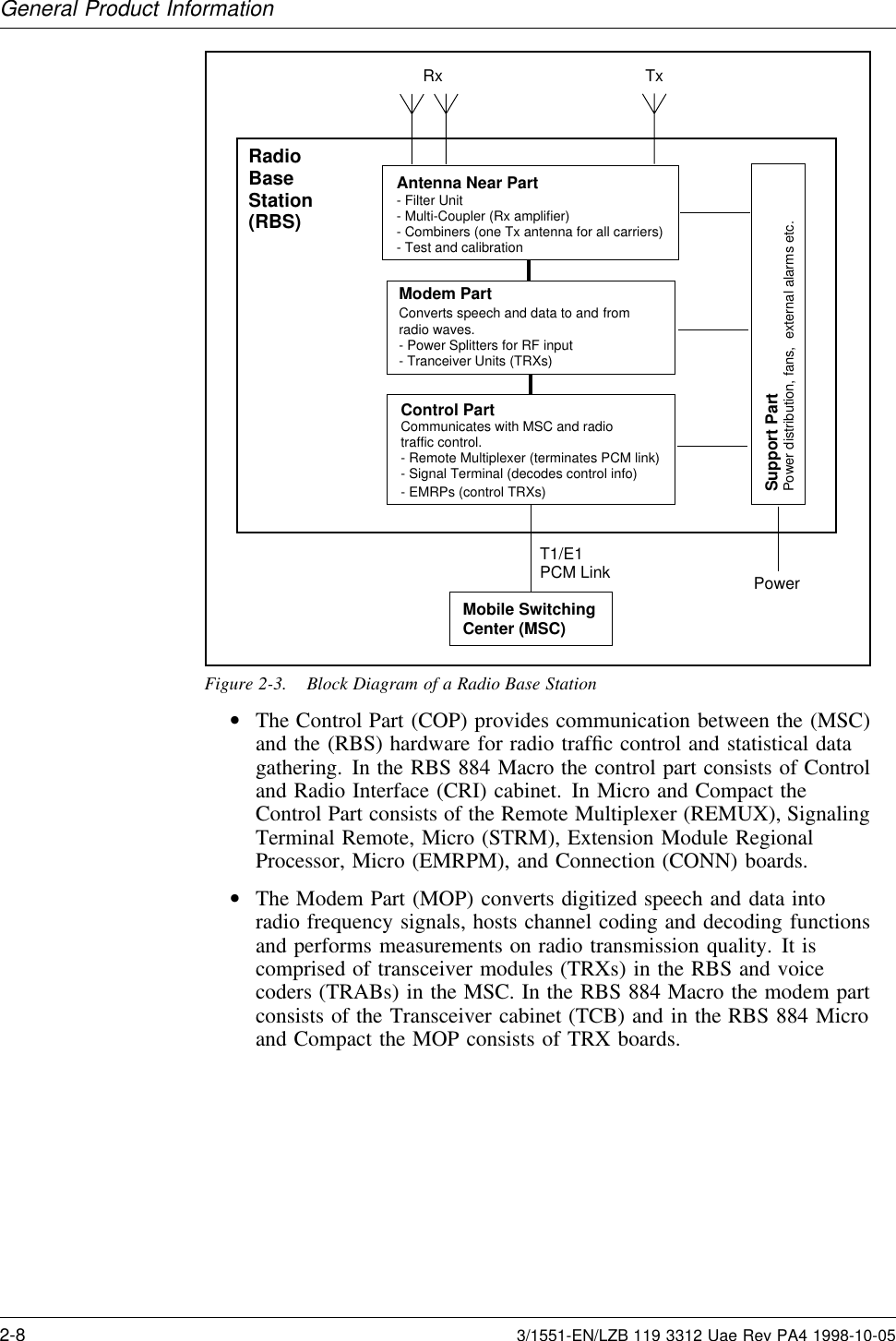
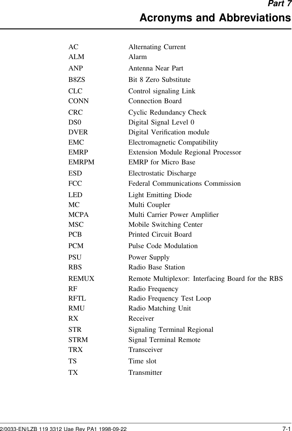
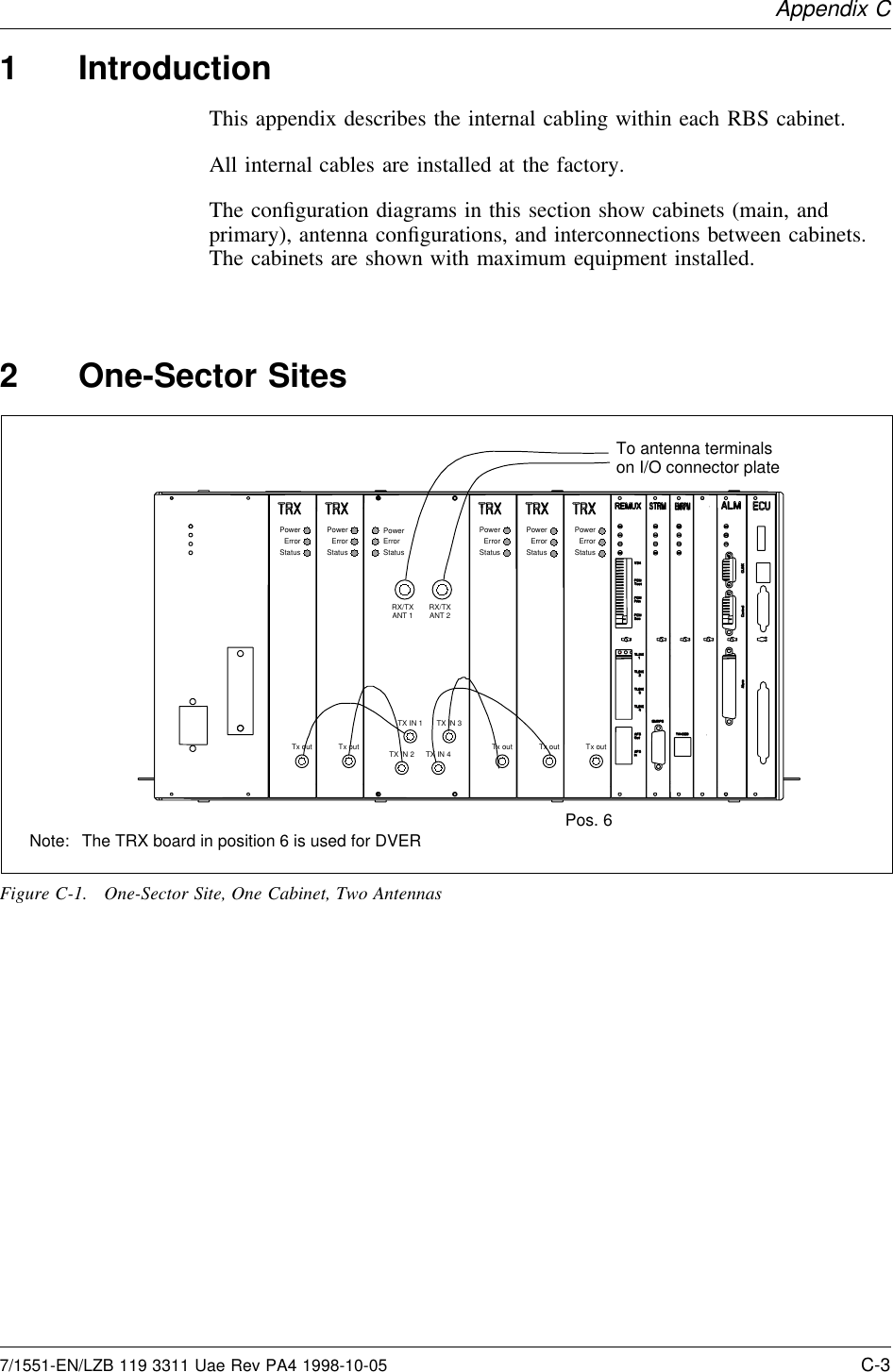
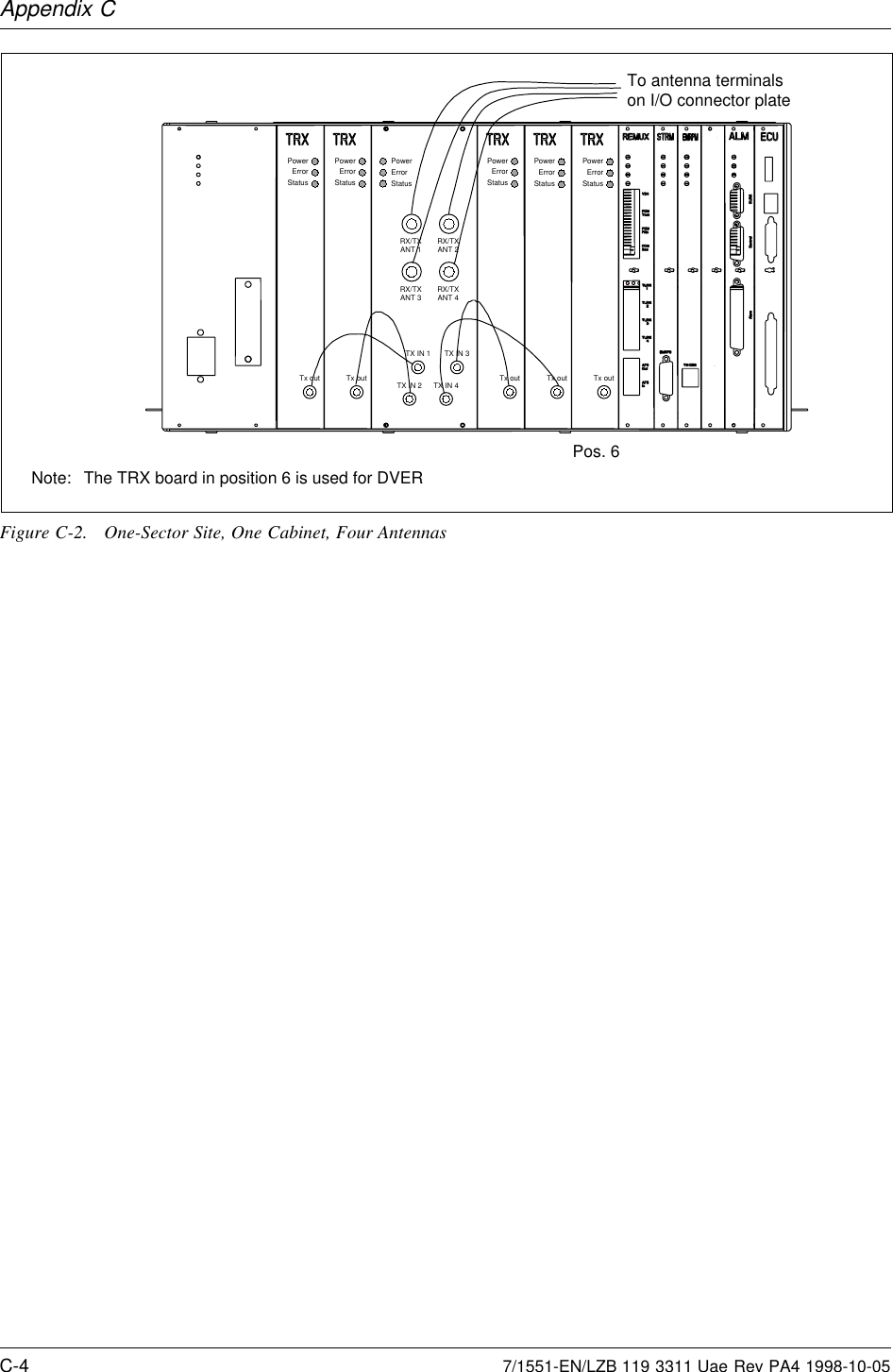
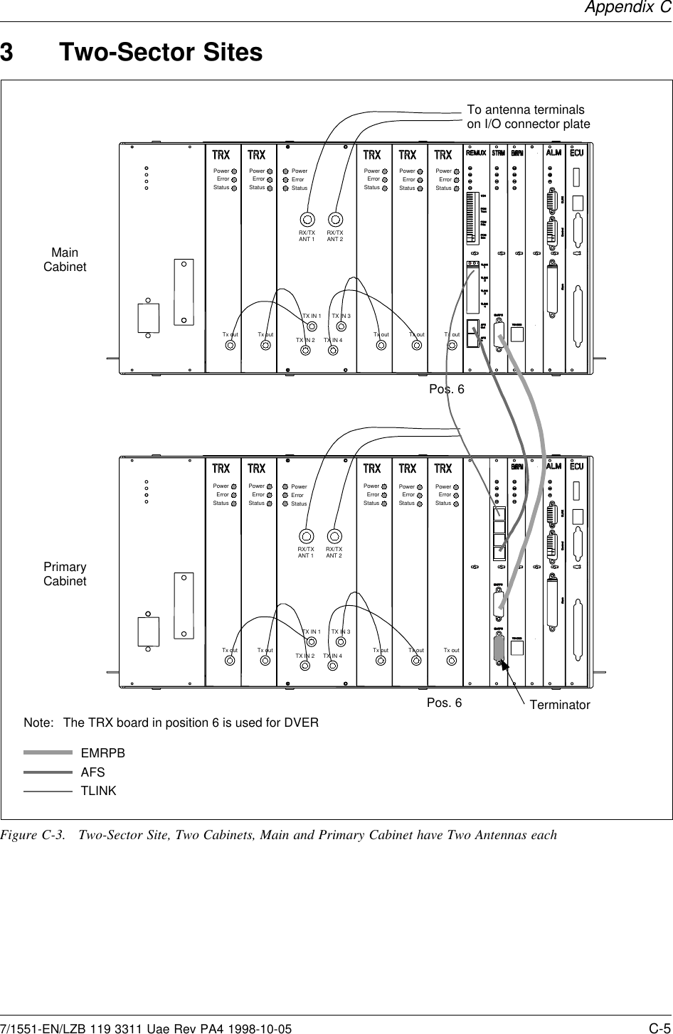
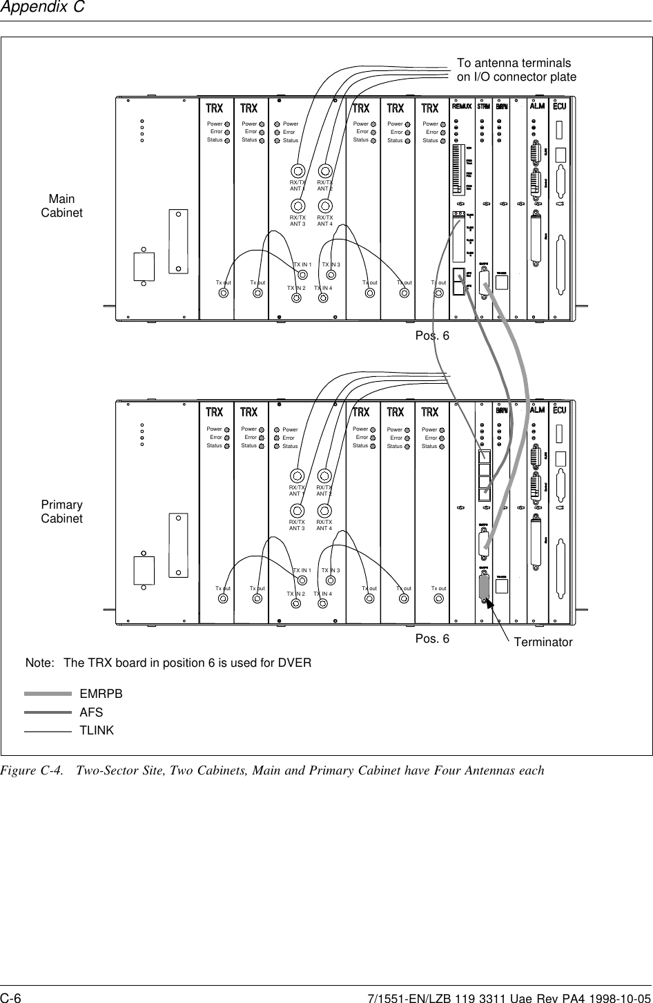
Instruction maintenance manual
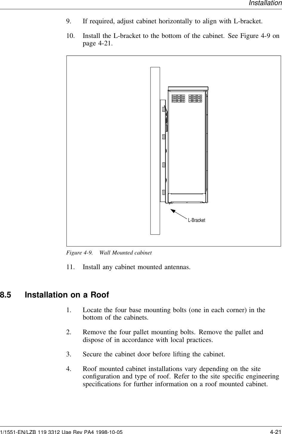
Contents
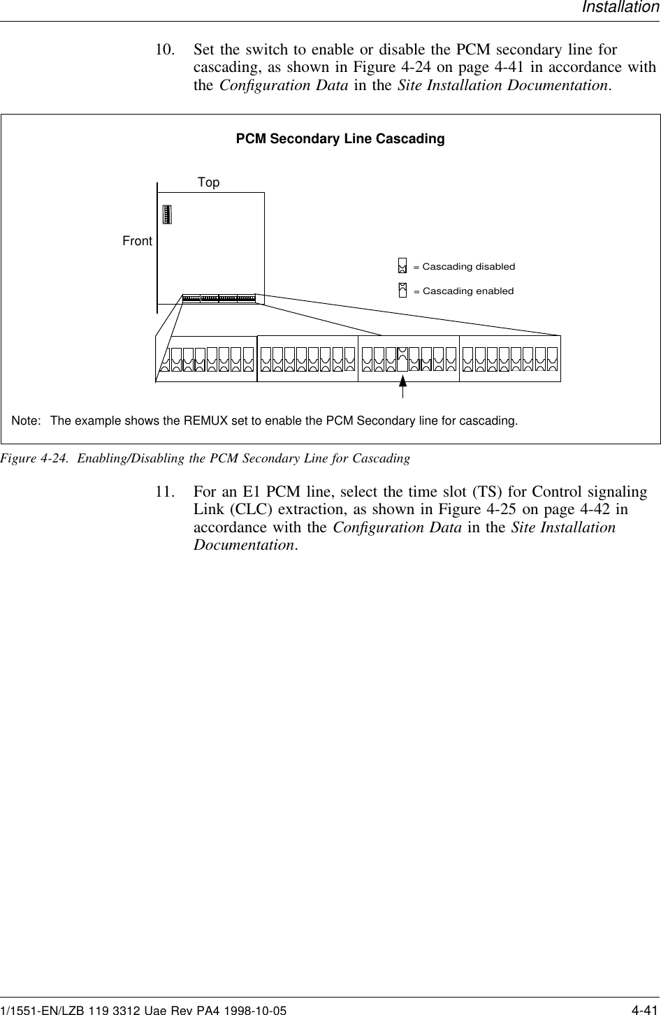
1.
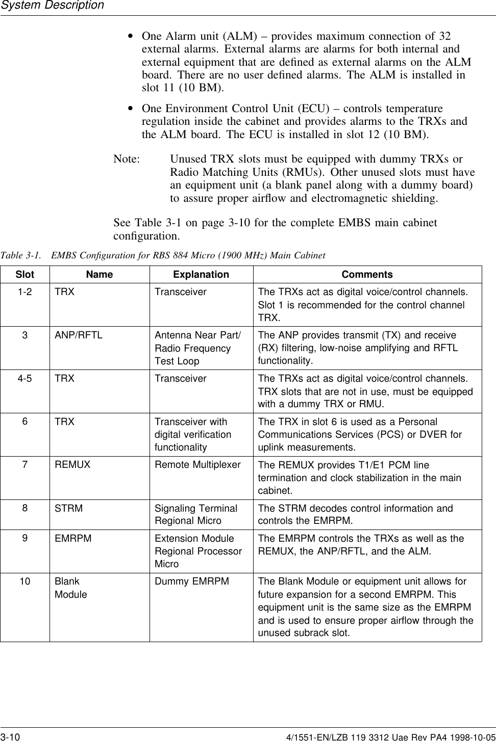
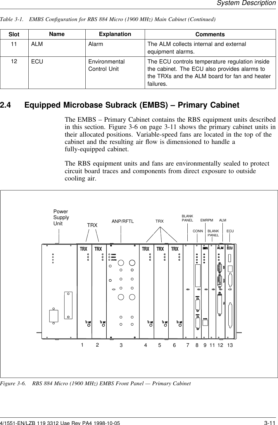
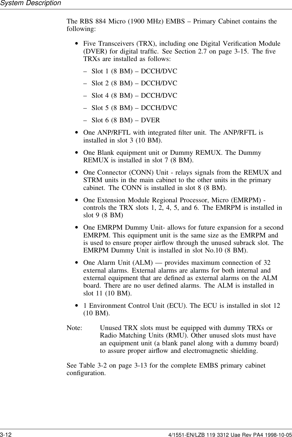
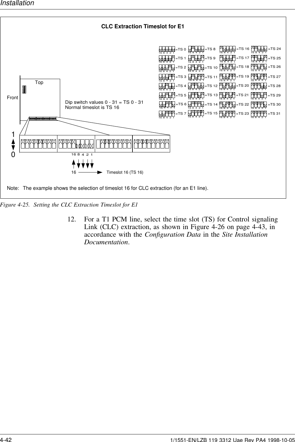
Instruction maintenance manual
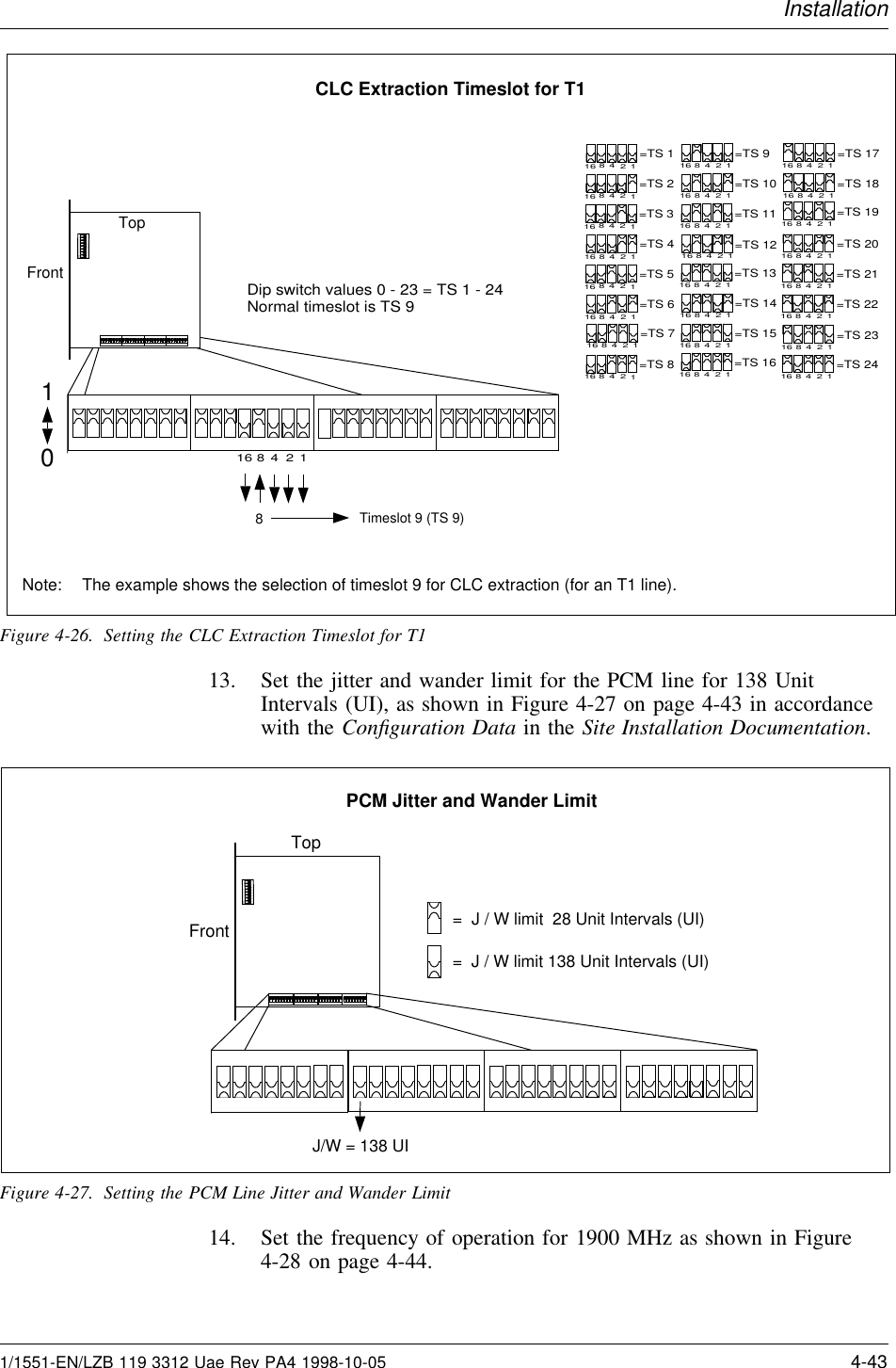
2.
PDF instruction manual
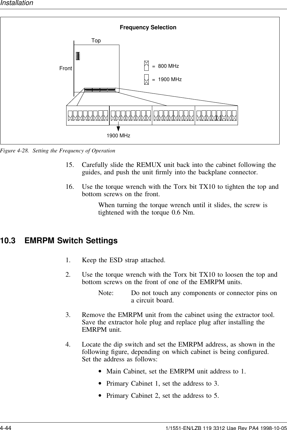
Instruction maintenance manual
Navigation menu
Upload a User Manual
Namespaces
Wiki Guide
HTML
PDF
Info
Views
User Manual
Discussion / Help
Navigation