HARRIS KRC121106-1 User Manual PubTeX output 1998 12 03 1743
HARRIS CORPORATION PubTeX output 1998 12 03 1743
UserManual.wiki
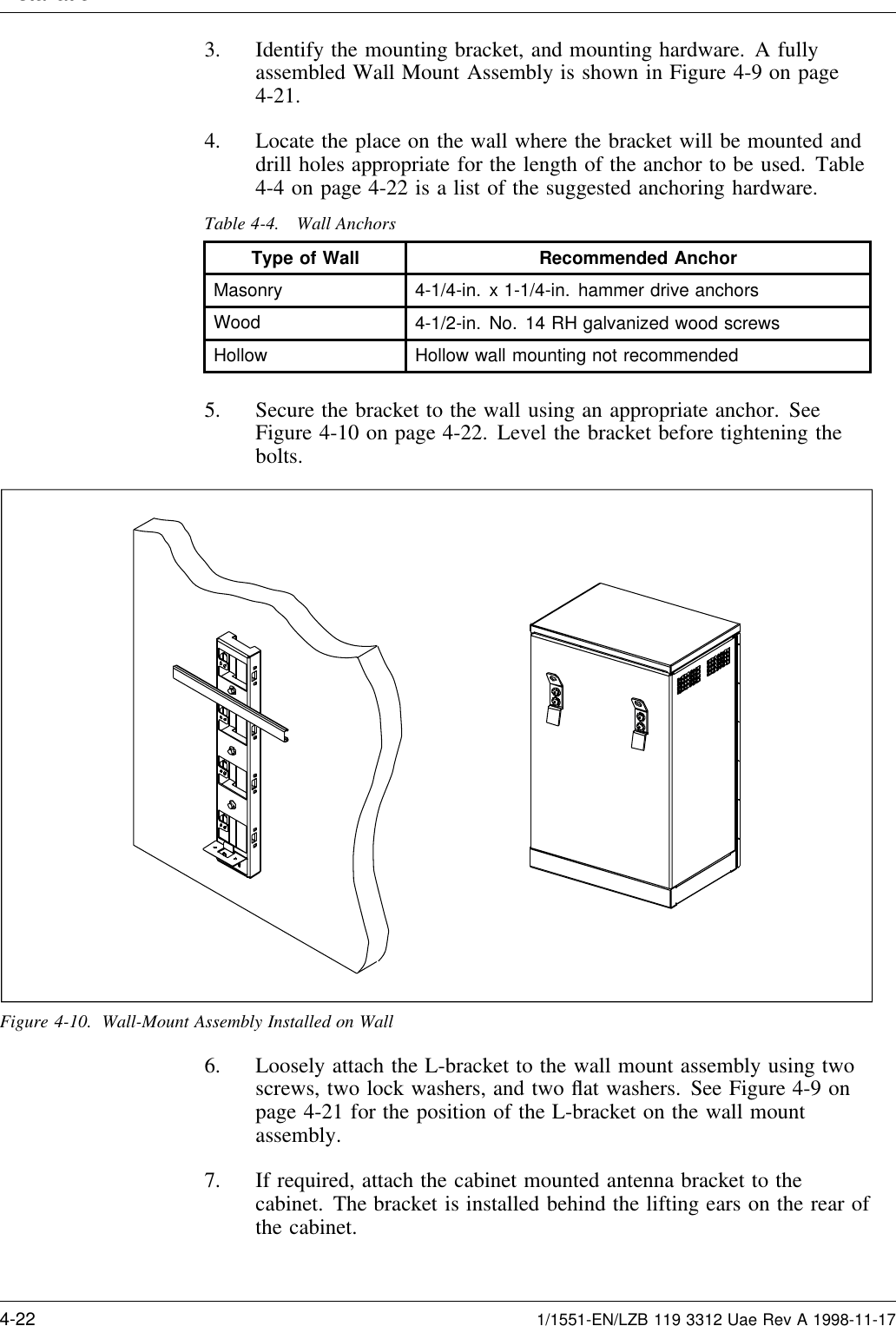
>
HARRIS
>
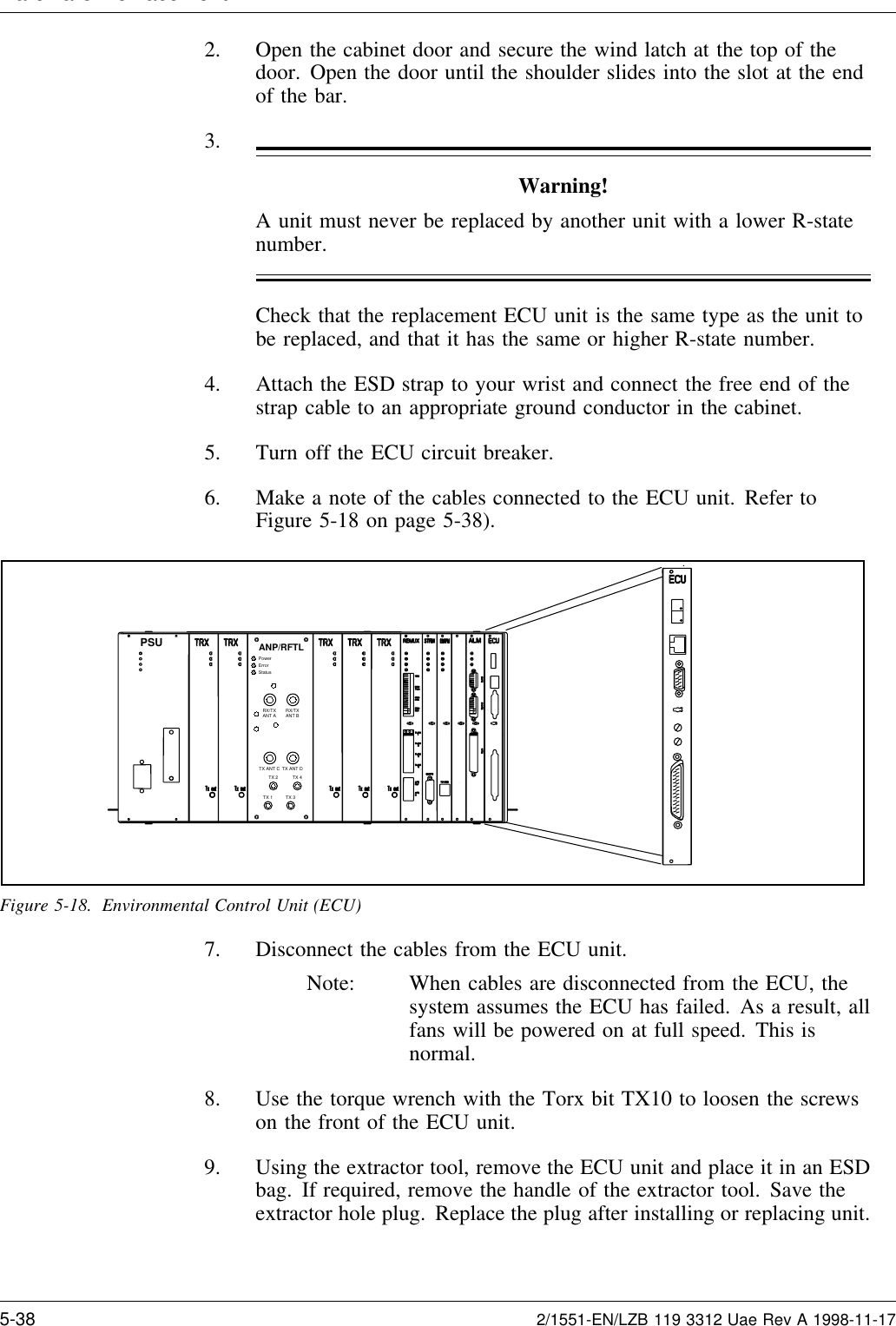
KRC121106-1 User Manual
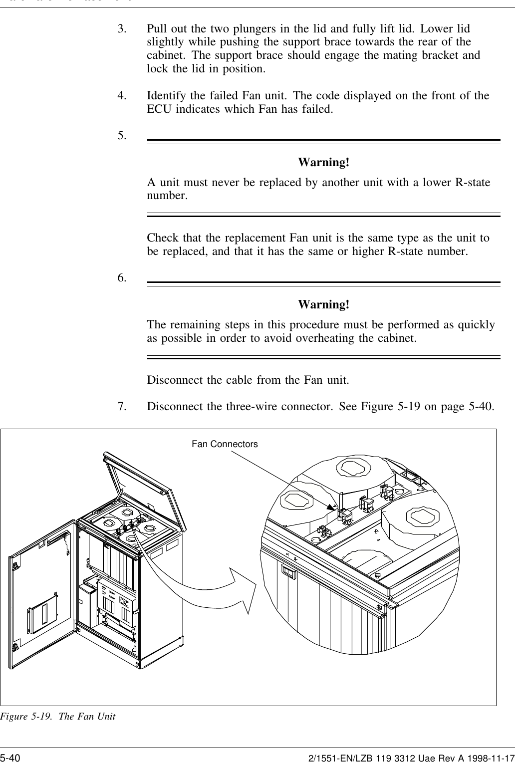
>
PDF instruction manual
Contents
1.
Instruction maintenance manual
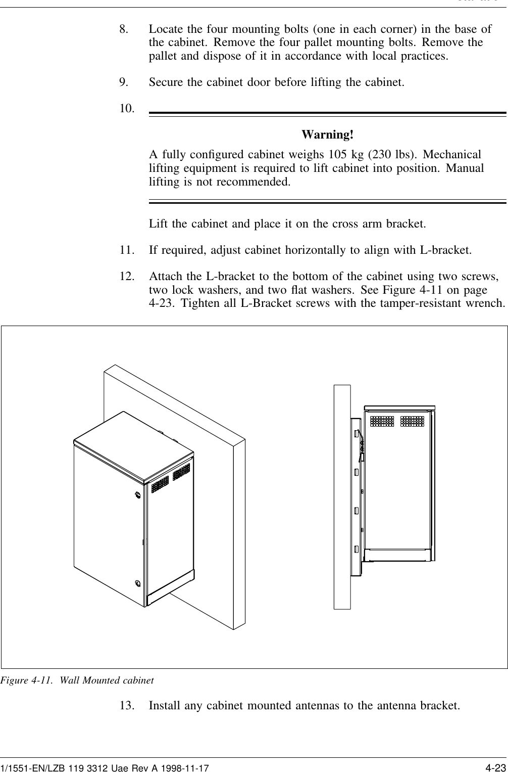
2.
PDF instruction manual
PDF instruction manual
Navigation menu
Upload a User Manual
Namespaces
Wiki Guide
HTML
PDF
Info
Views
User Manual
Discussion / Help
Navigation
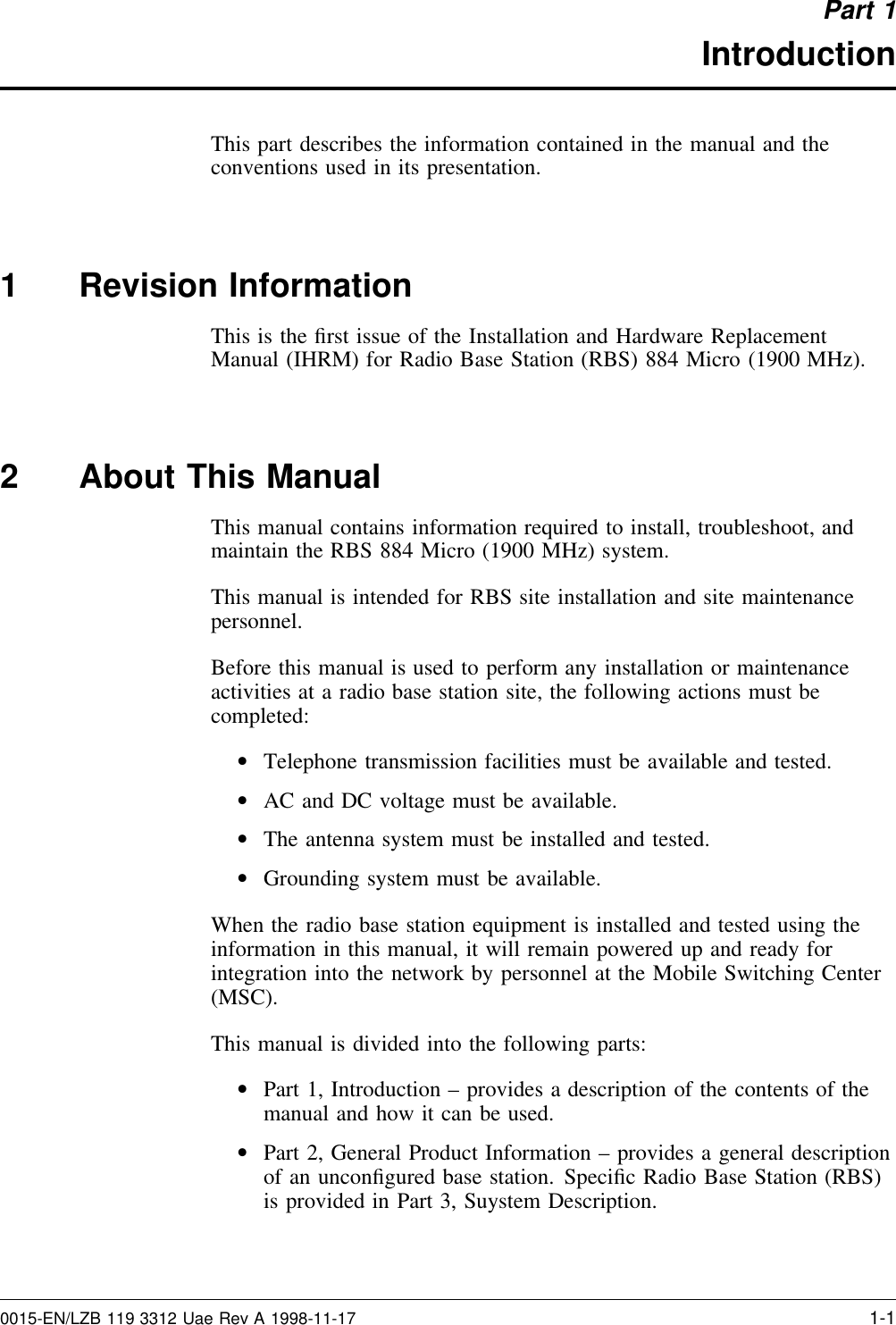

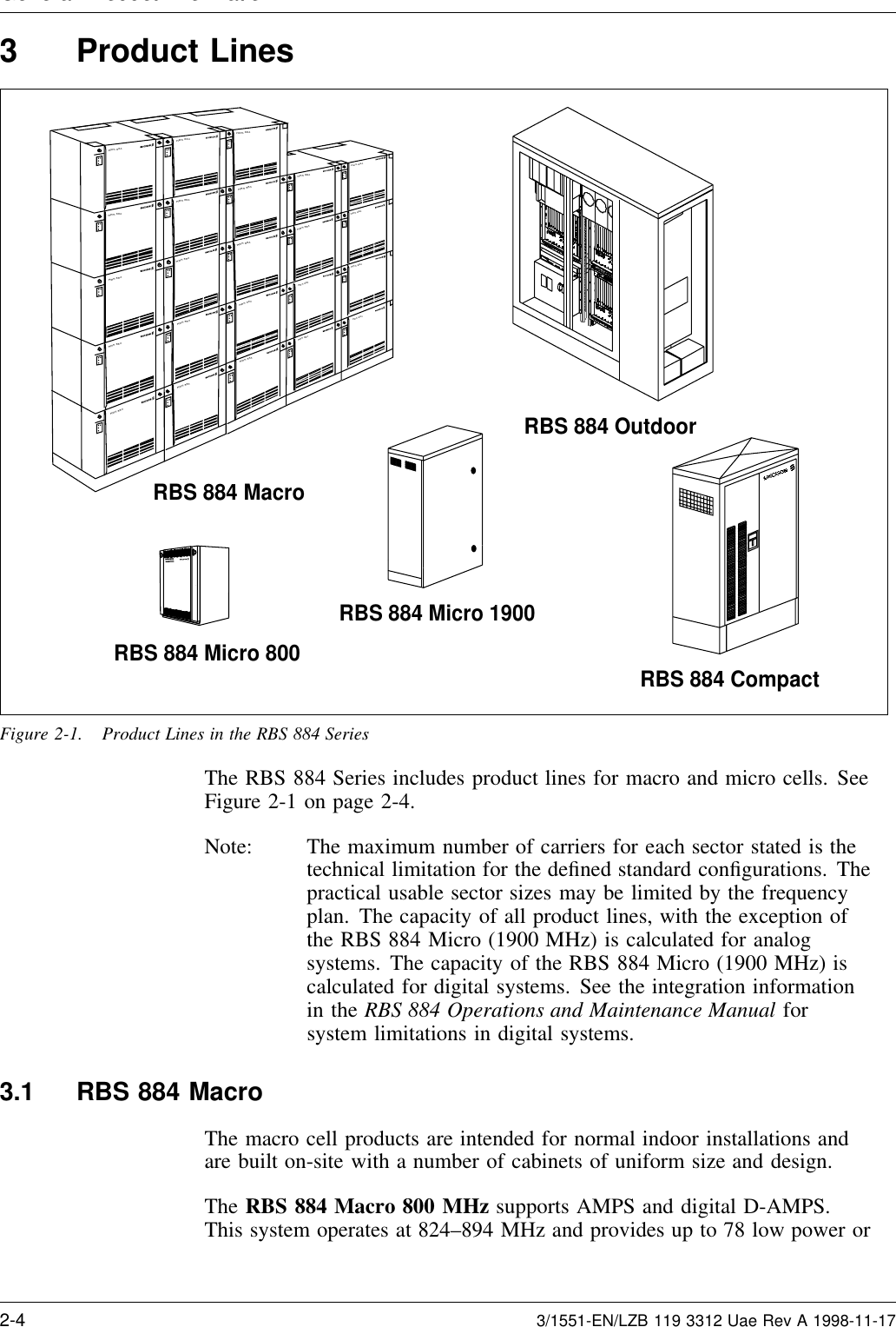


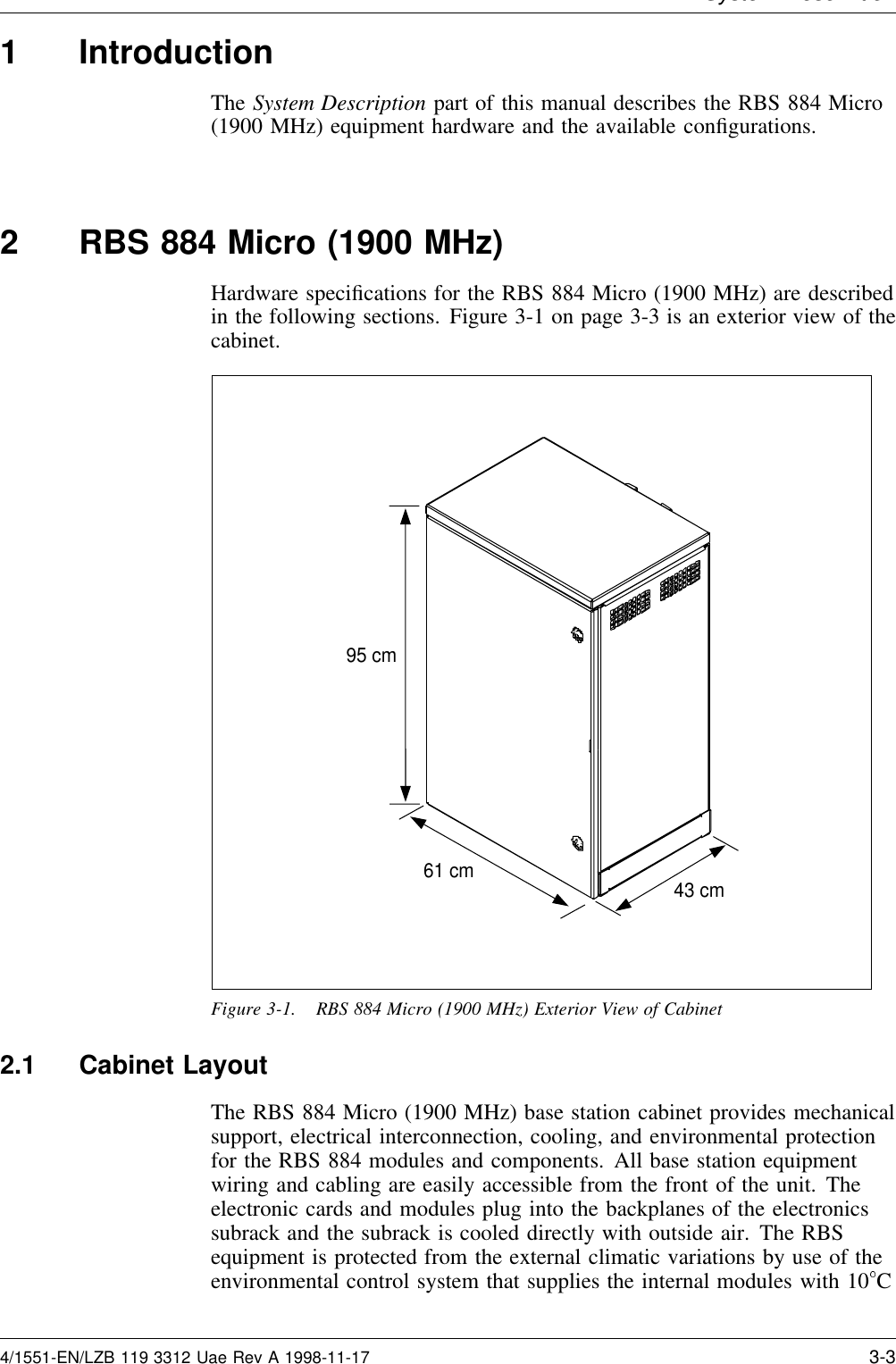
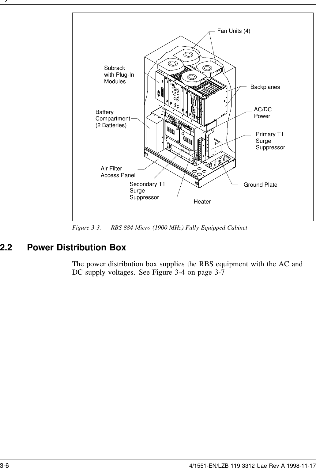
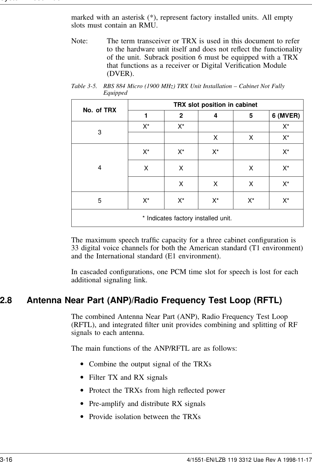
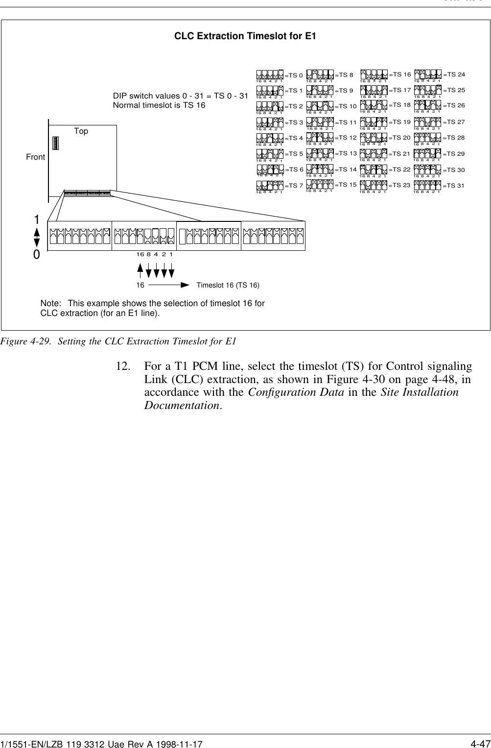
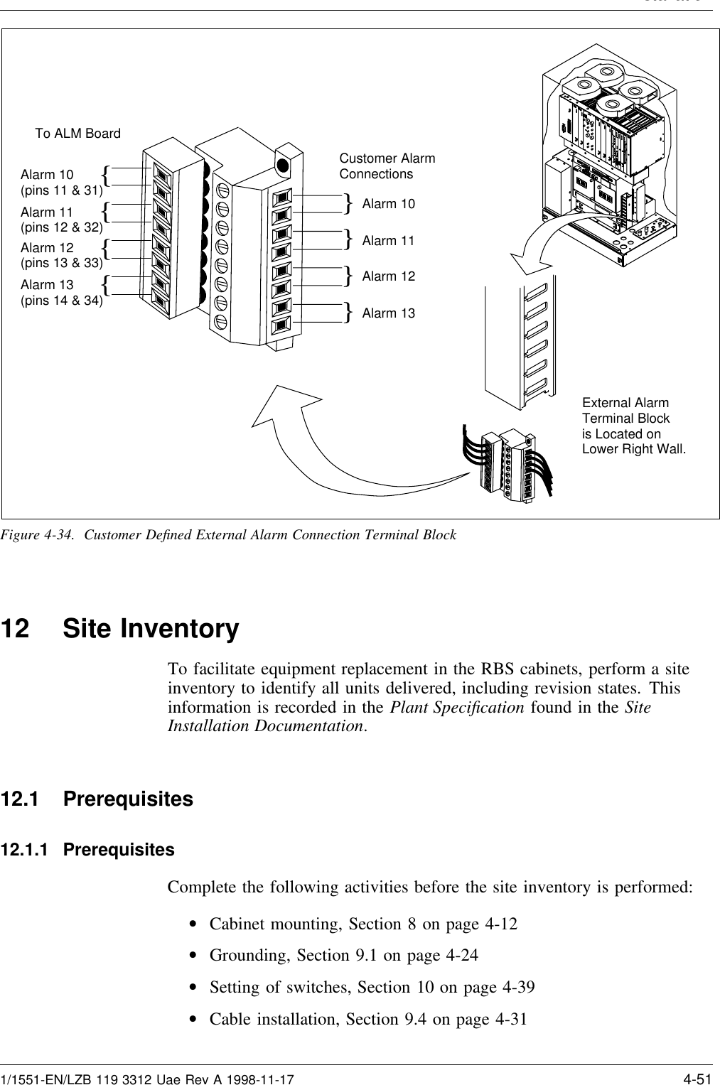
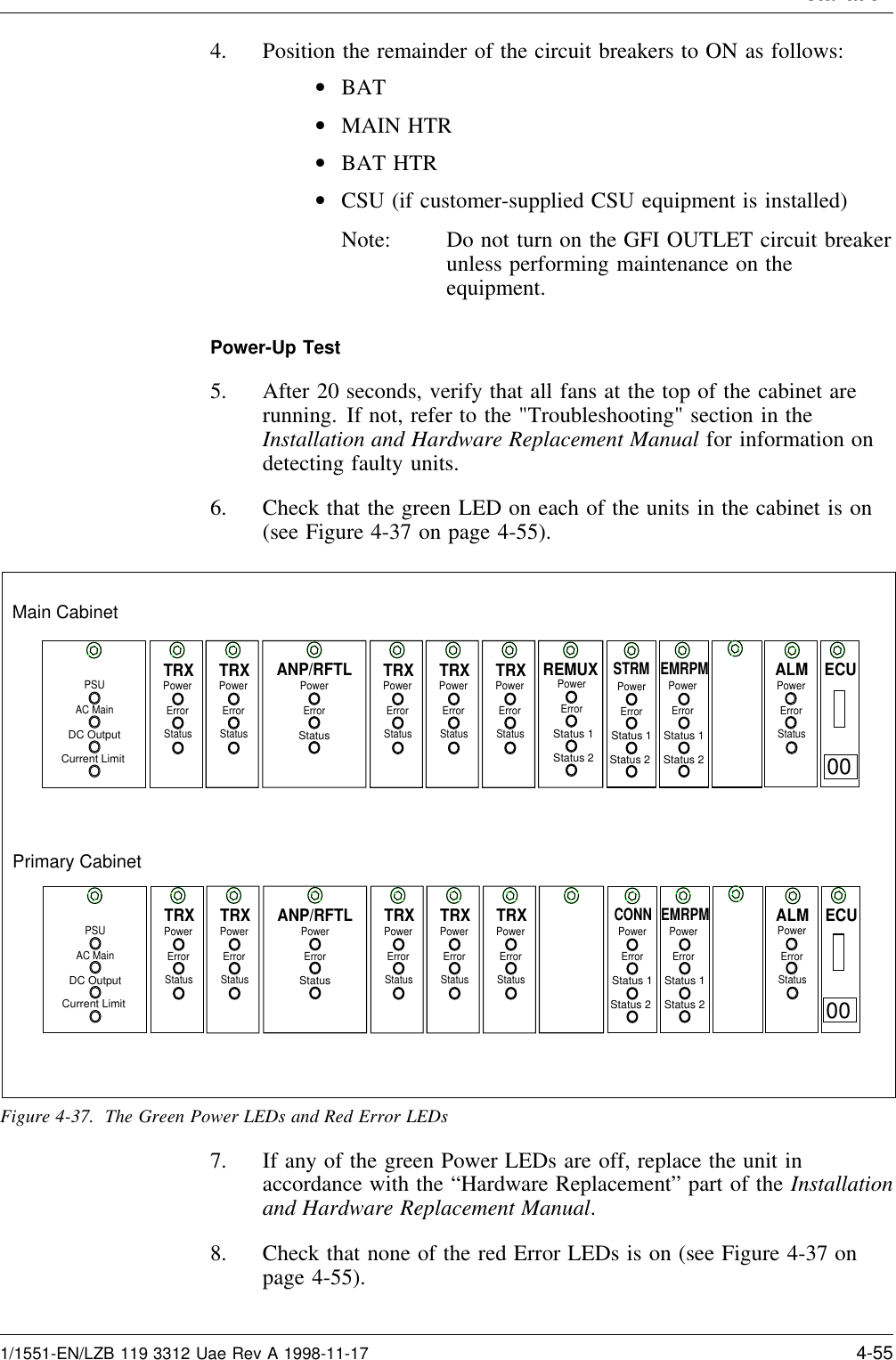
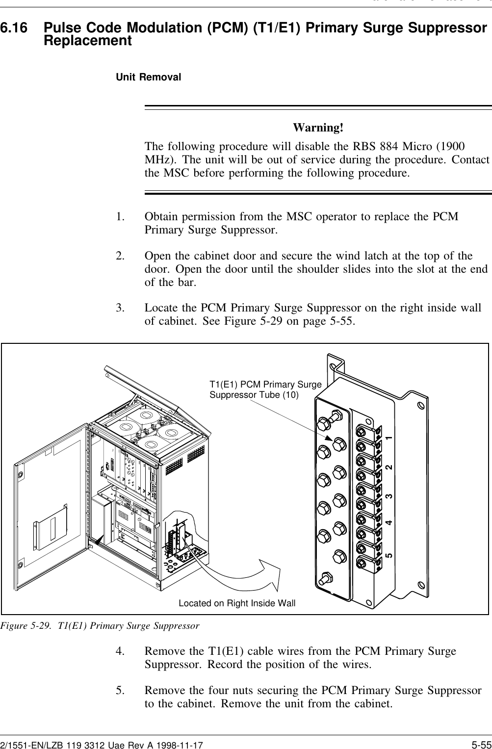
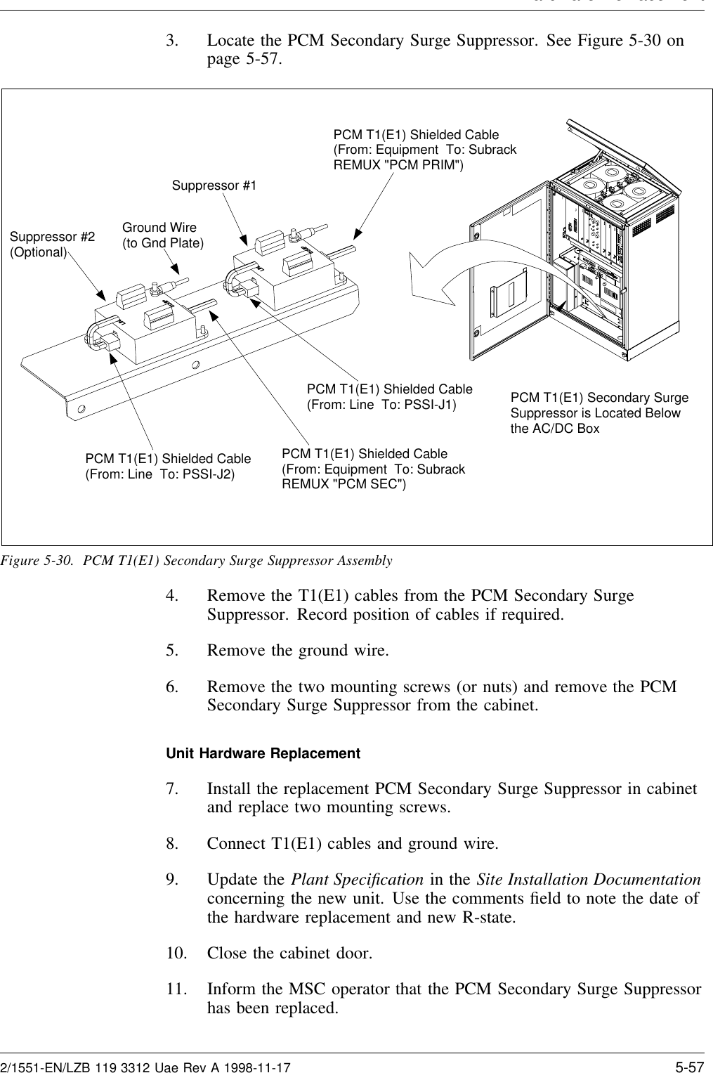
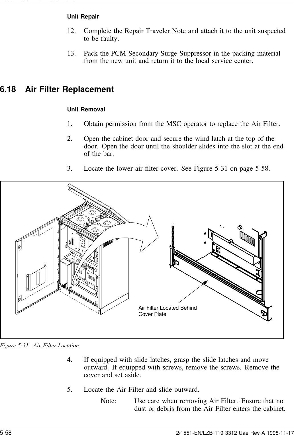
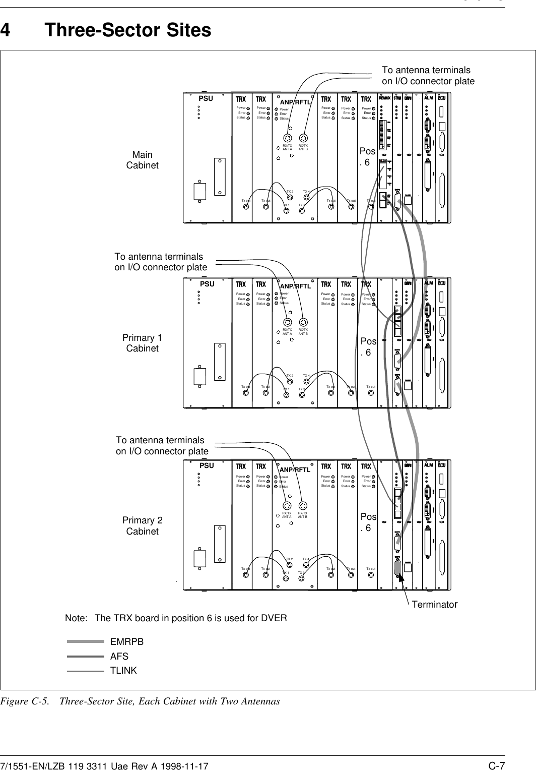
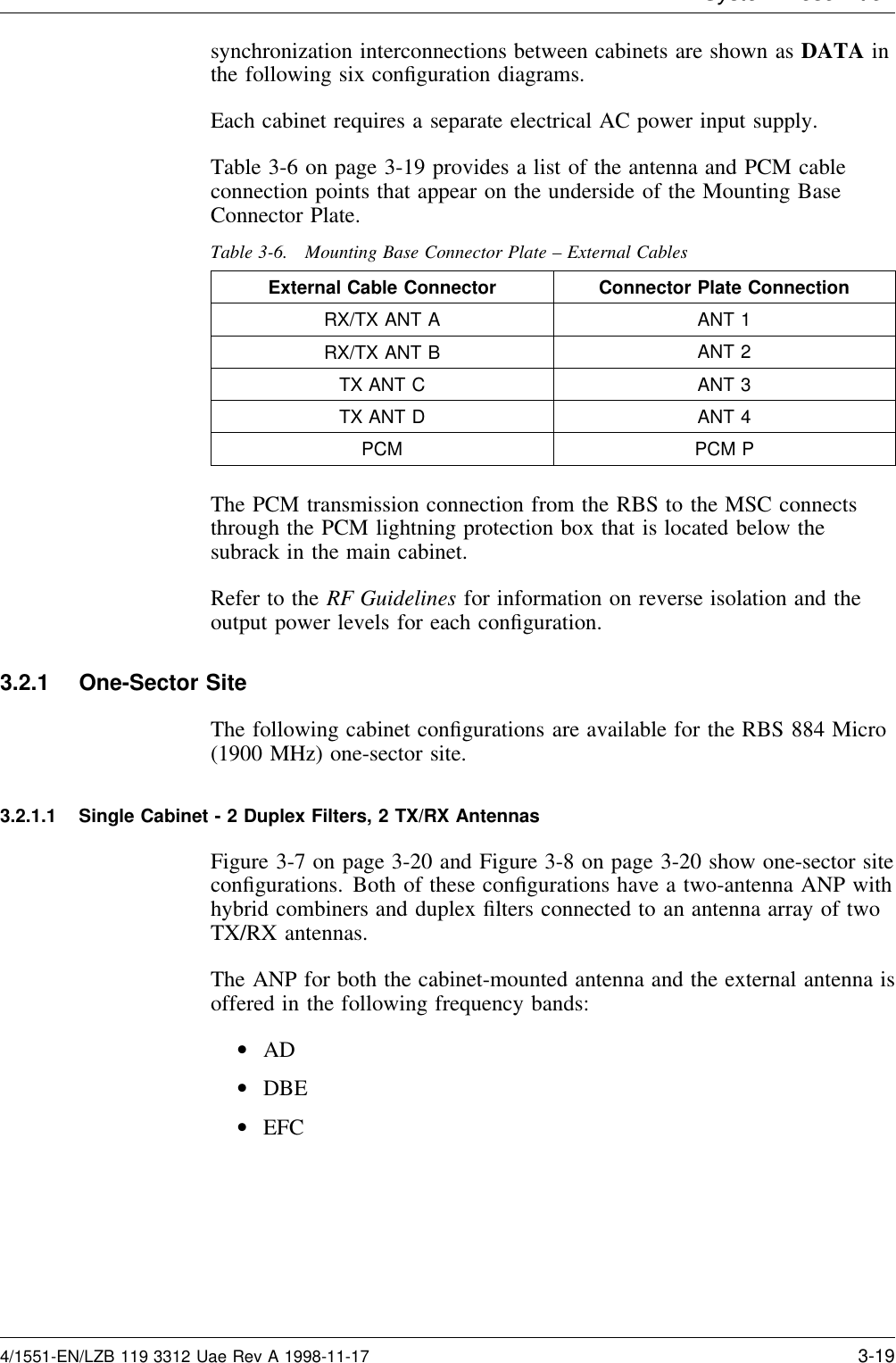
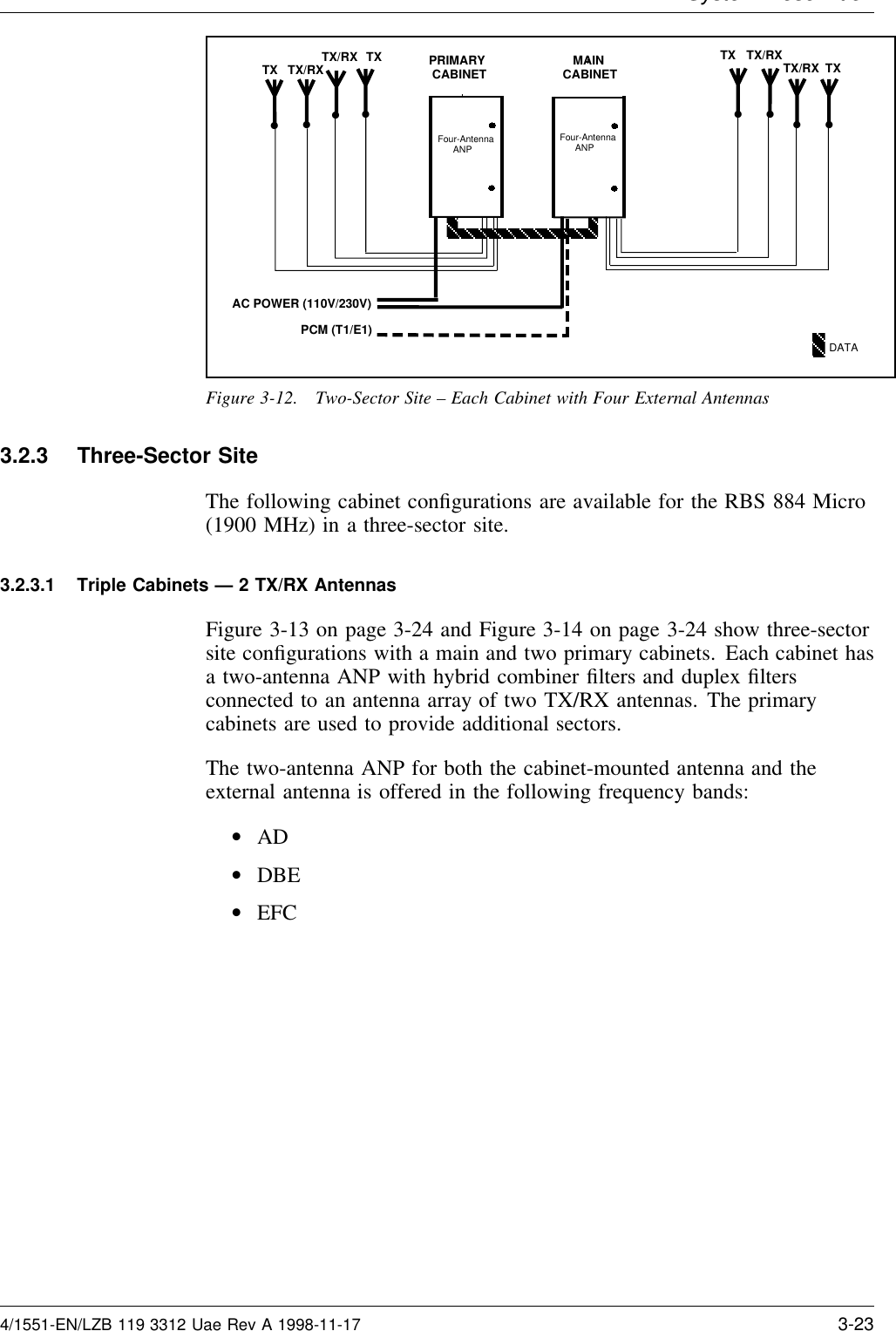
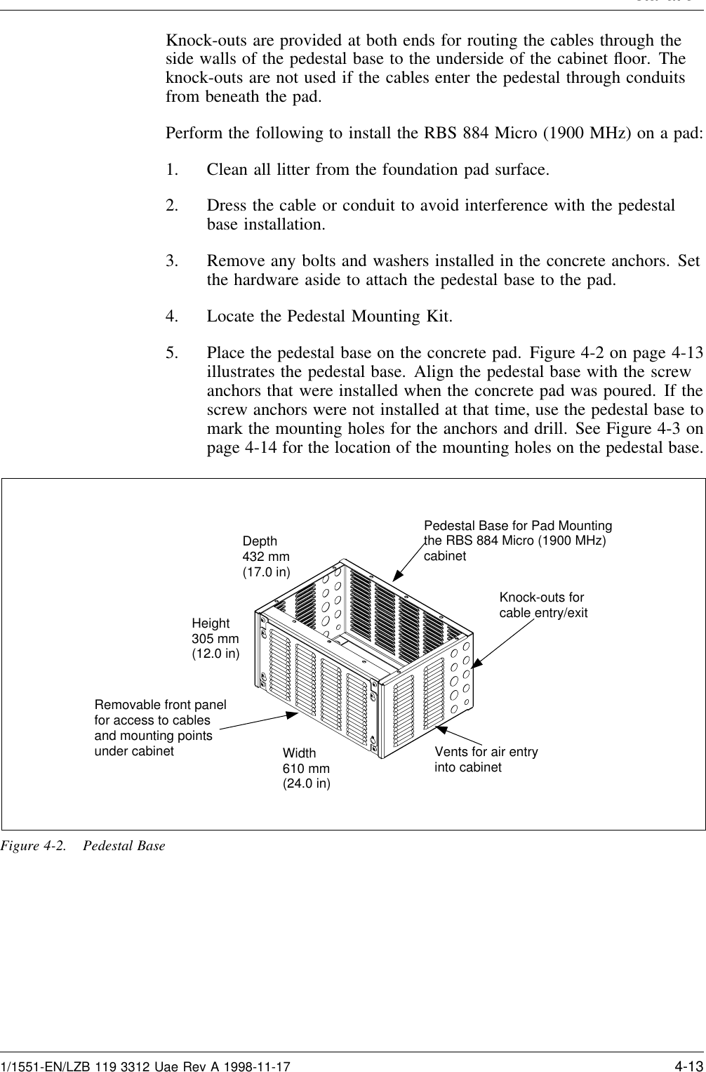
![System Descri tion2.11 Air FilterThe RBS 884 Micro (1900 MHz) cabinet is equipped with a cooling airintake filter. The lower front panel of the cabinet is removable to gainaccess for periodic filter replacement.3 Installation Configurations3.1 LimitationsOne RBS cabinet can contain up to five TRXs, four of which can be usedfor handling speech traffic.3.2 Standard Configurations RBS 884 Micro (1900 MHz)The RBS 884 Micro (1900 MHz) cabinets are configured and assembled atthe factory before delivery to the RBS site. It is the responsibility of thesite engineer to dimension the required configuration.When considering which configuration to choose, dimension the TRXunits. The RBS 884 Micro (1900 MHz) can contain as few as three TRXunits per cabinet. Additional capacity can be added later.The RBS 884 Micro (1900 MHz) product contains a number of cabinetconfigurations depending on the following:•AC power voltage: 110V 60 Hz or 230V 50 Hz•Type of transmission: E1 or T1•Antenna configuration: 2 or 4 antennas– Two antenna mounting: cabinet-mounted or external– Four antenna mounting: external•Frequency band: AD, DBE, or EFC•Number of TRXs: 3, 4, or 5 (including 1 Digital Verification[DVER] unit)The number of cabinets required at the RBS site can be one, two, or three,depending on the number of TRX units and sectors determined for thatspecific RBS site. The 1900 MHz base station cabinet can be configured toperform as a main or as a primary cabinet by installing the appropriateequipment units.The configuration diagrams in this section show cabinets (main, andprimary), PCM input, AC power input, antenna configurations, andinterconnections between cabinets. The cabinets are shown with maximumequipment installed. The PCM/TLINK/EMRPM, control, and3-18 4/1551-EN/LZB 119 3312 Uae Rev A 1998-11-17](https://usermanual.wiki/HARRIS/KRC121106-1.PDF-instruction-manual/User-Guide-15224-Page-34.png)
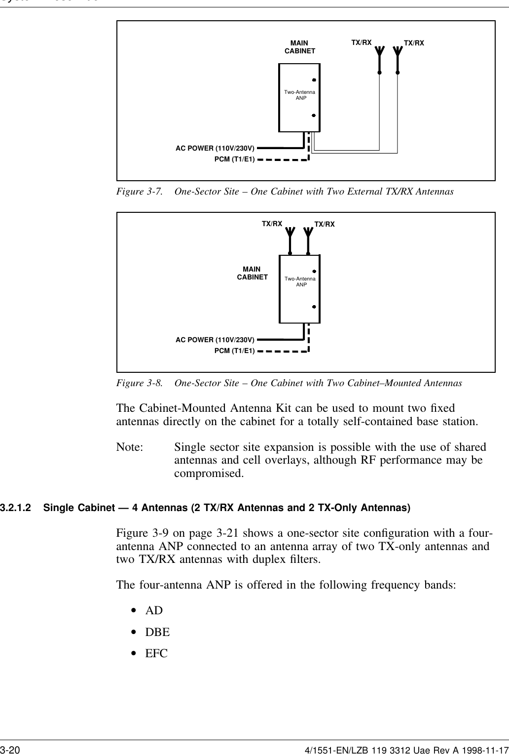
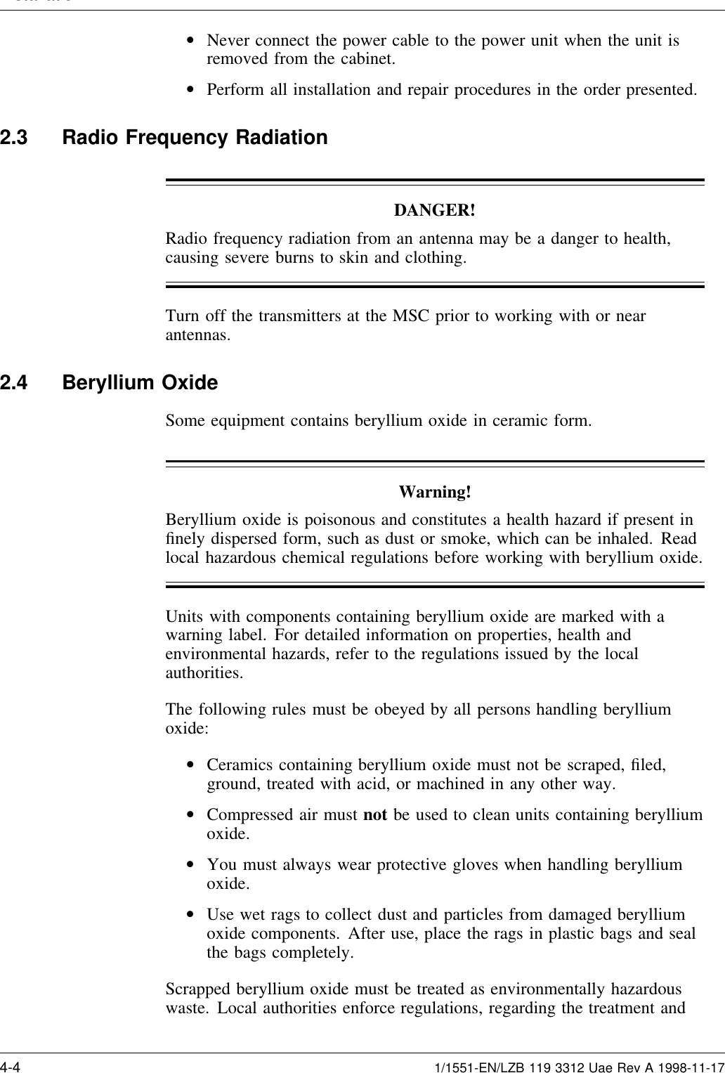
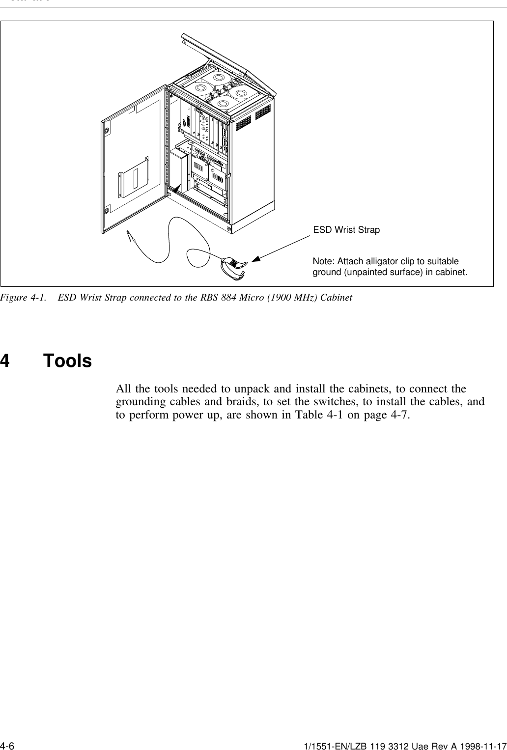

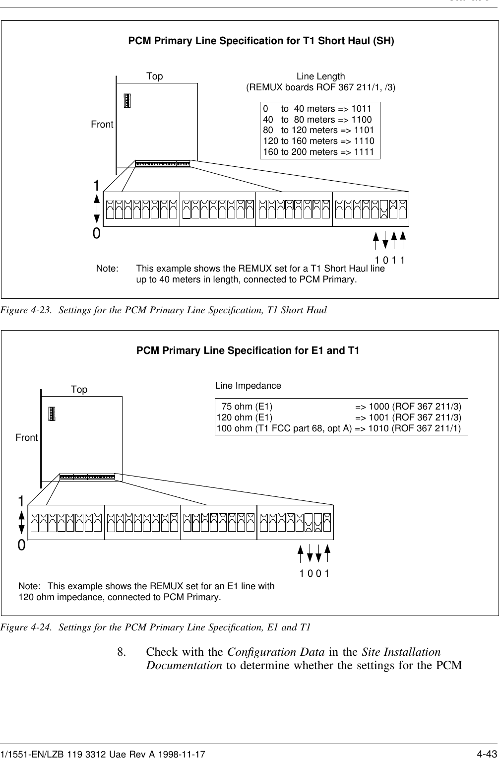
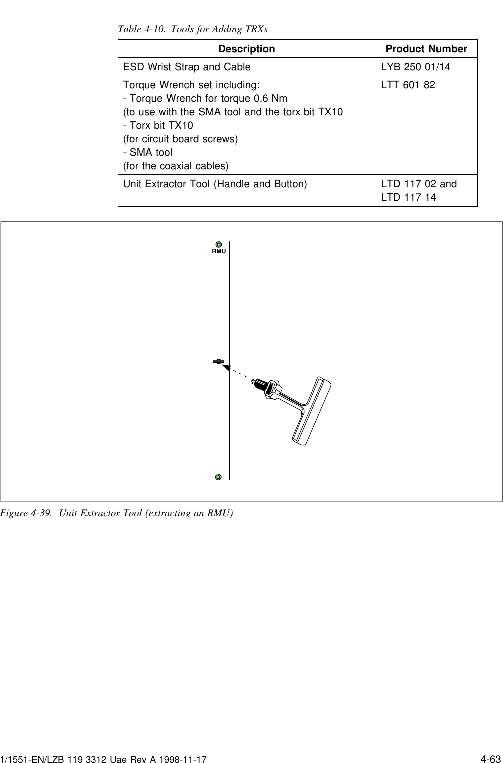
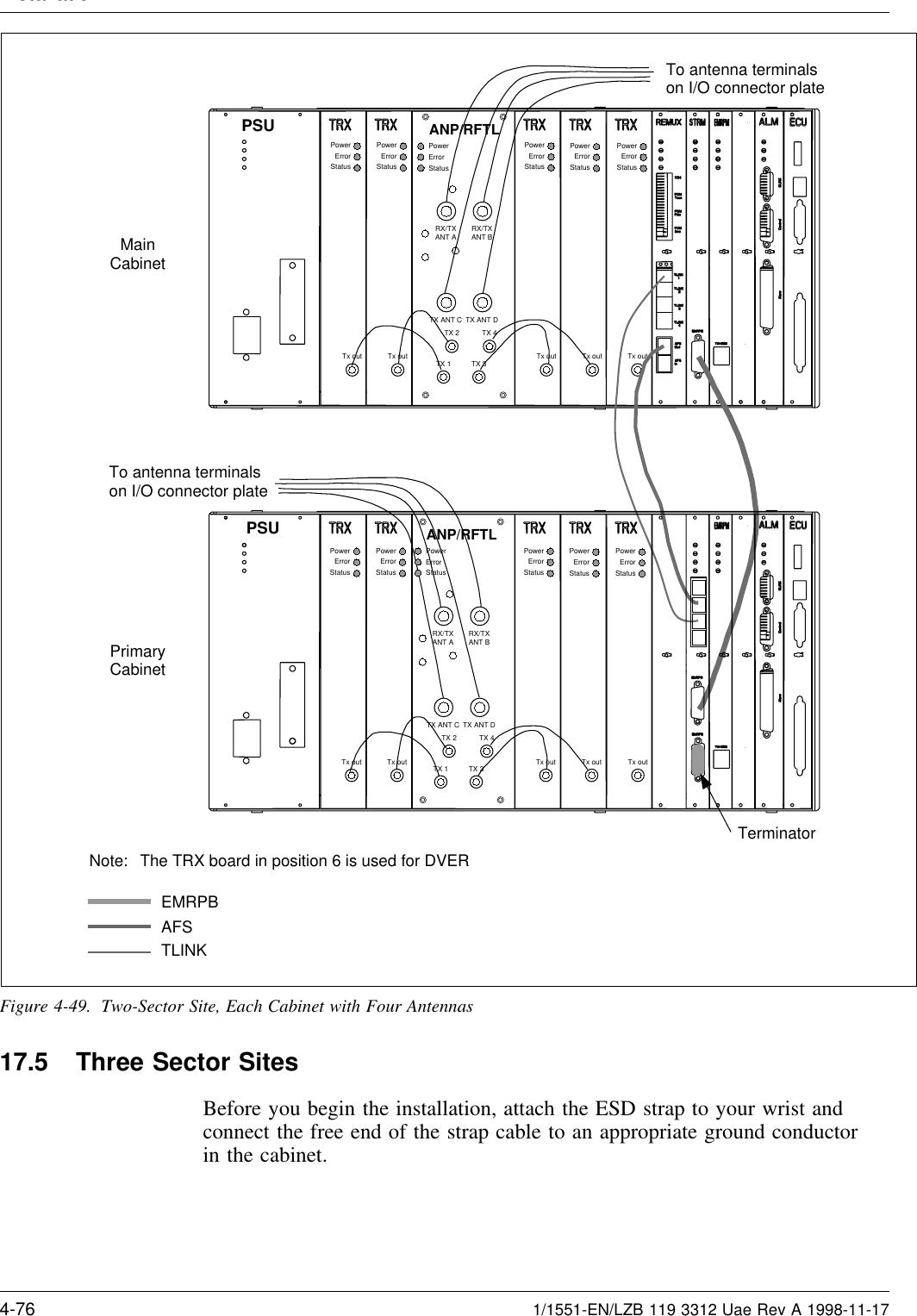
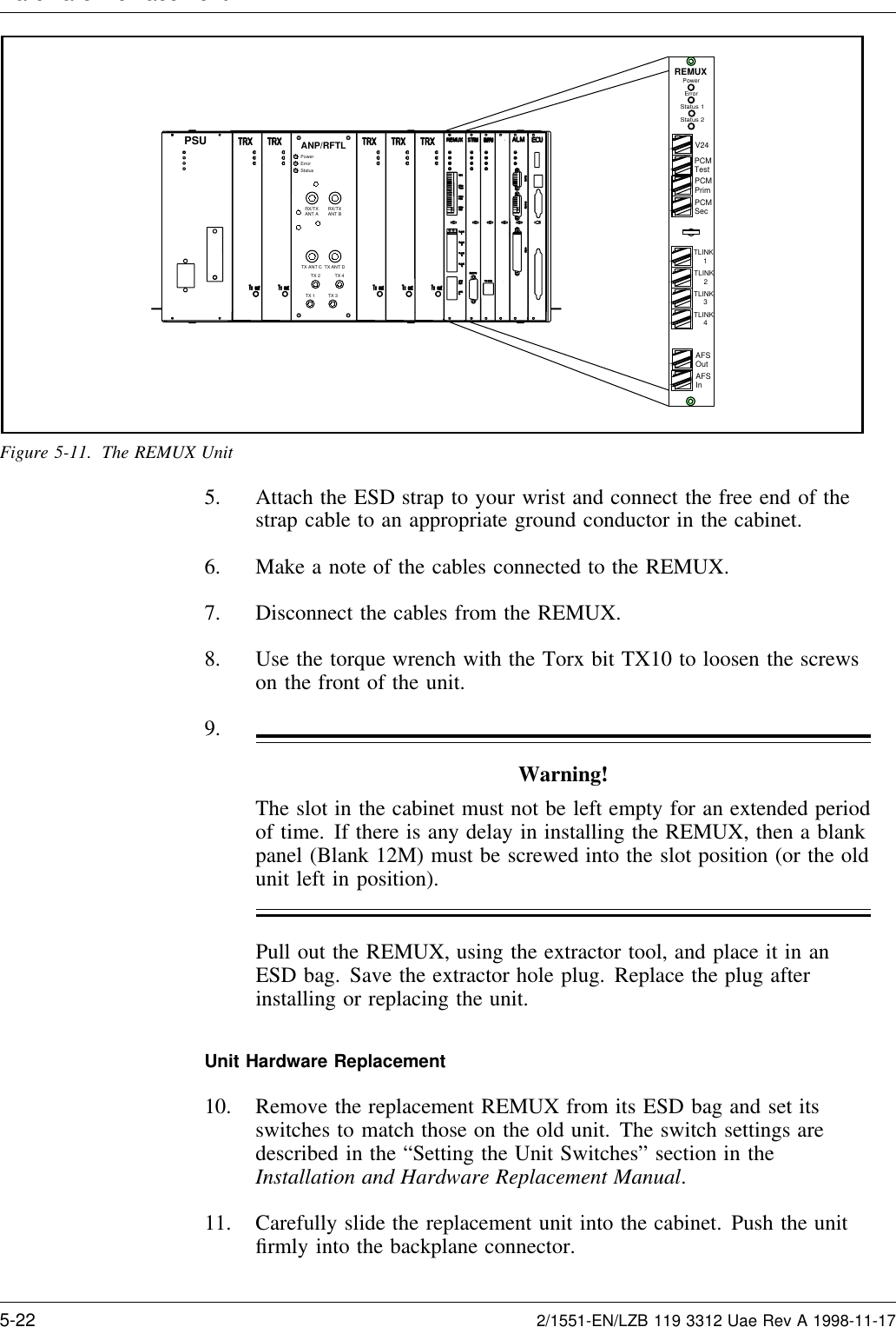
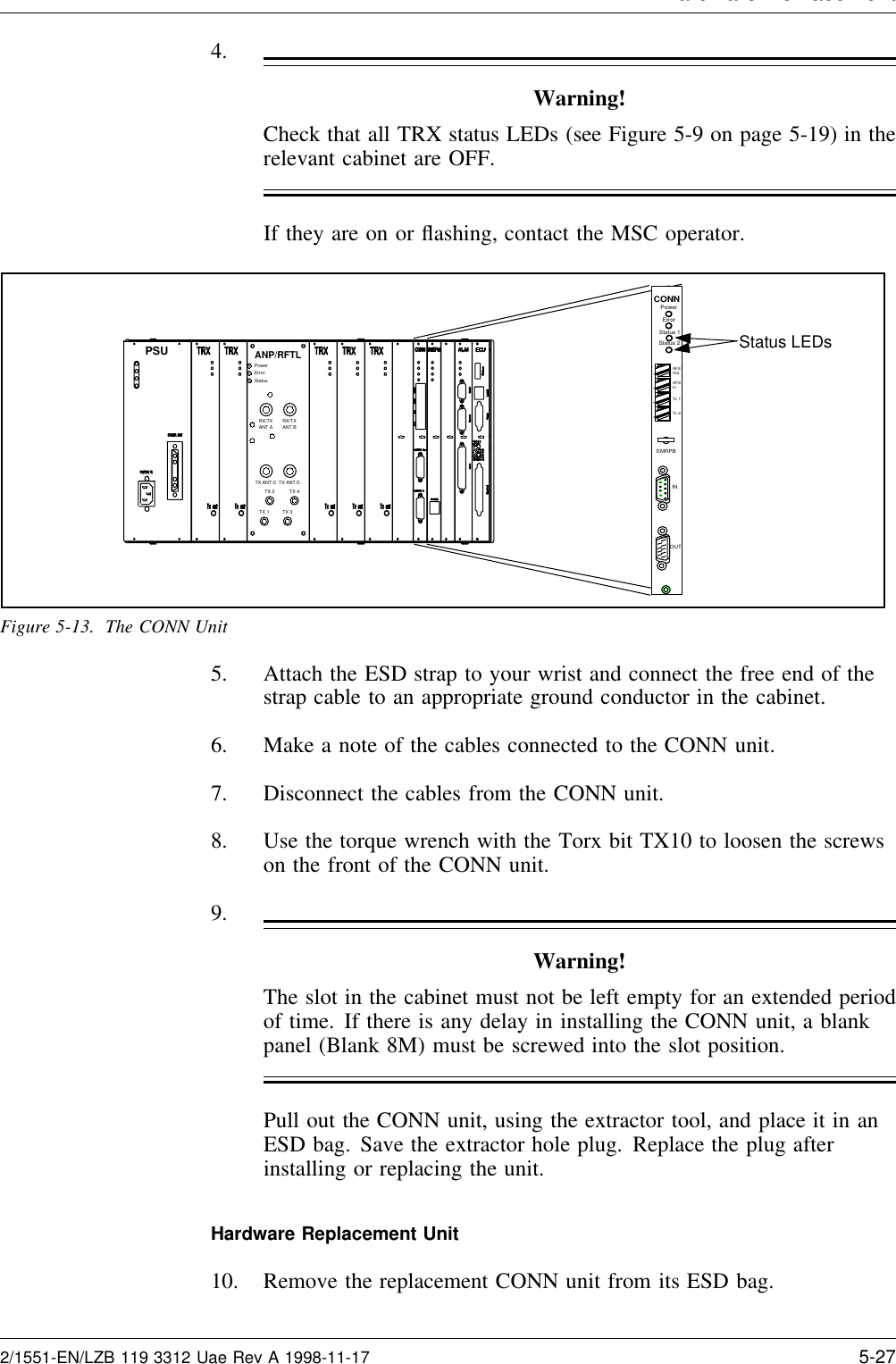
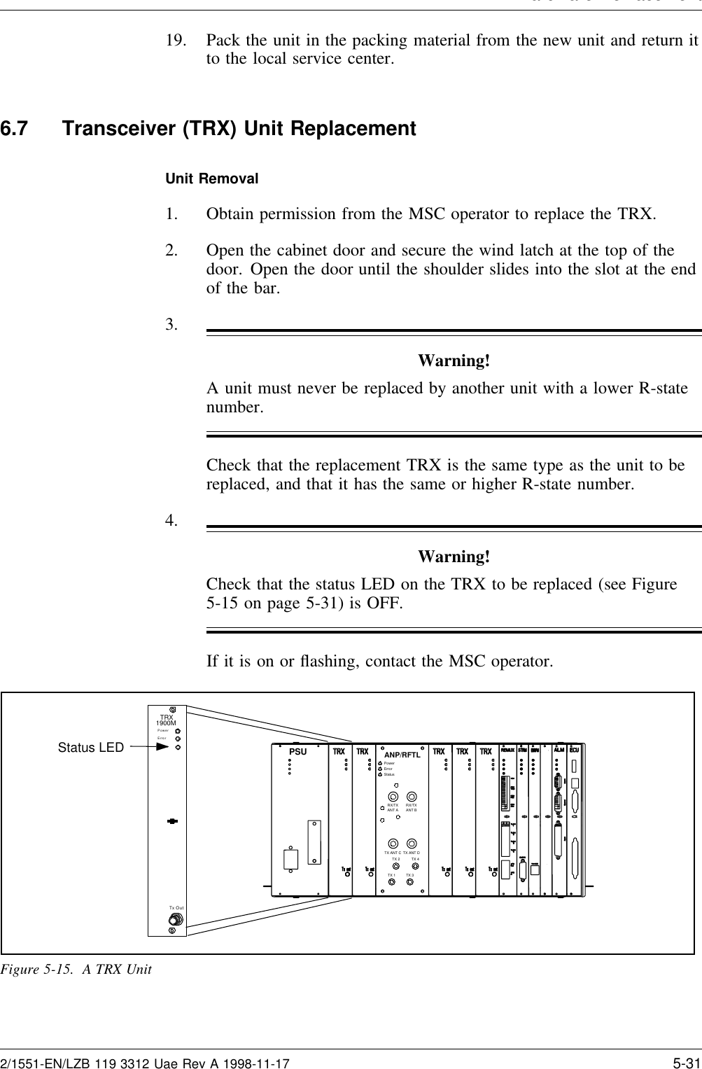
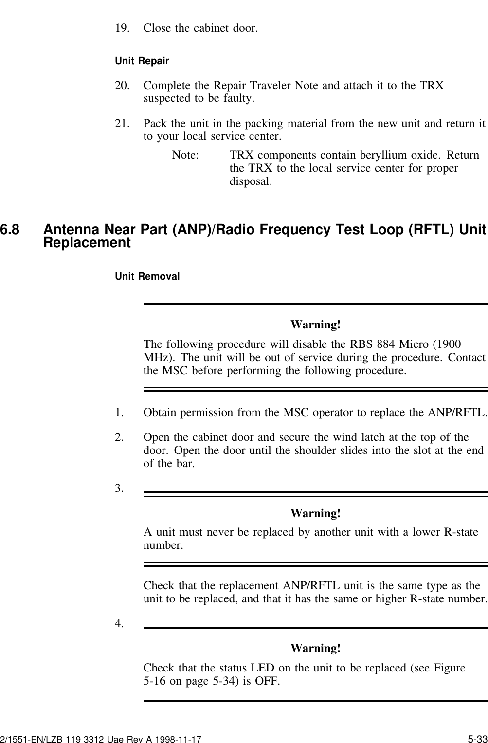
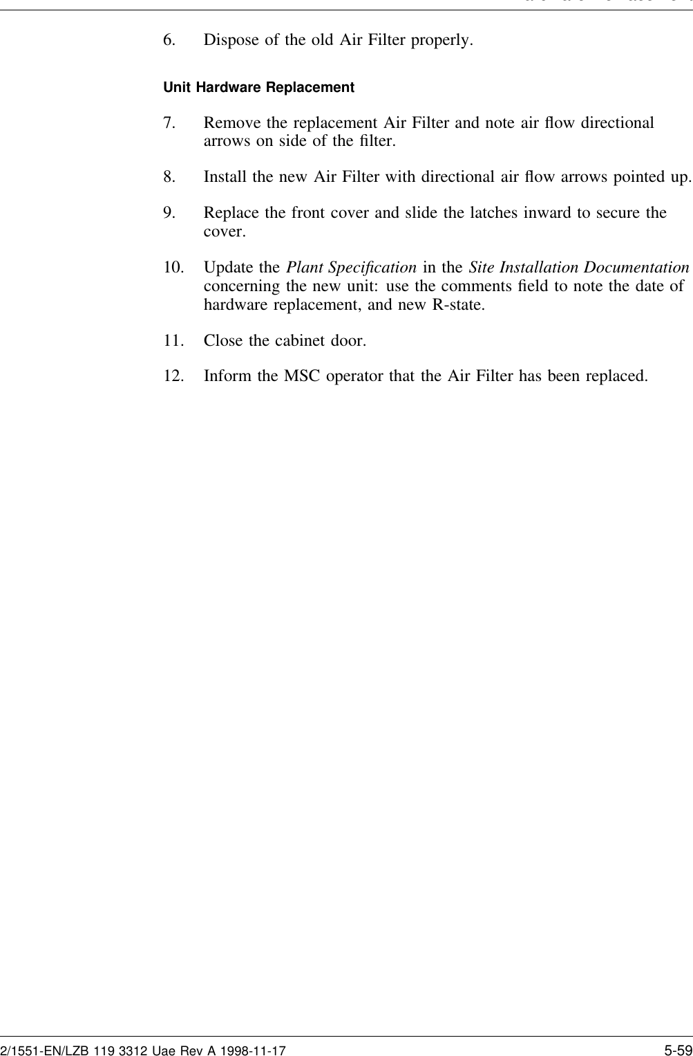
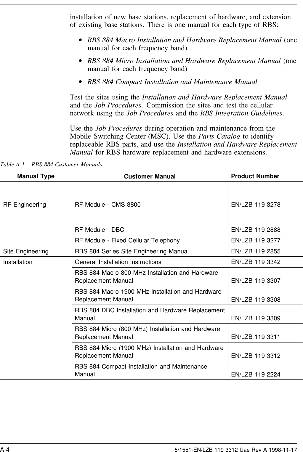
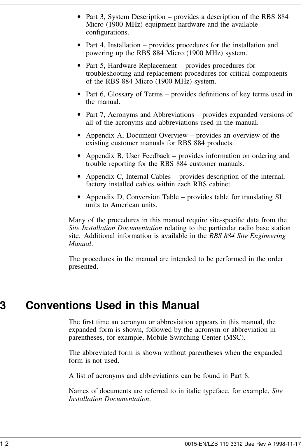
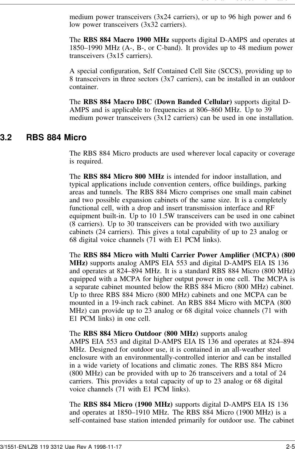
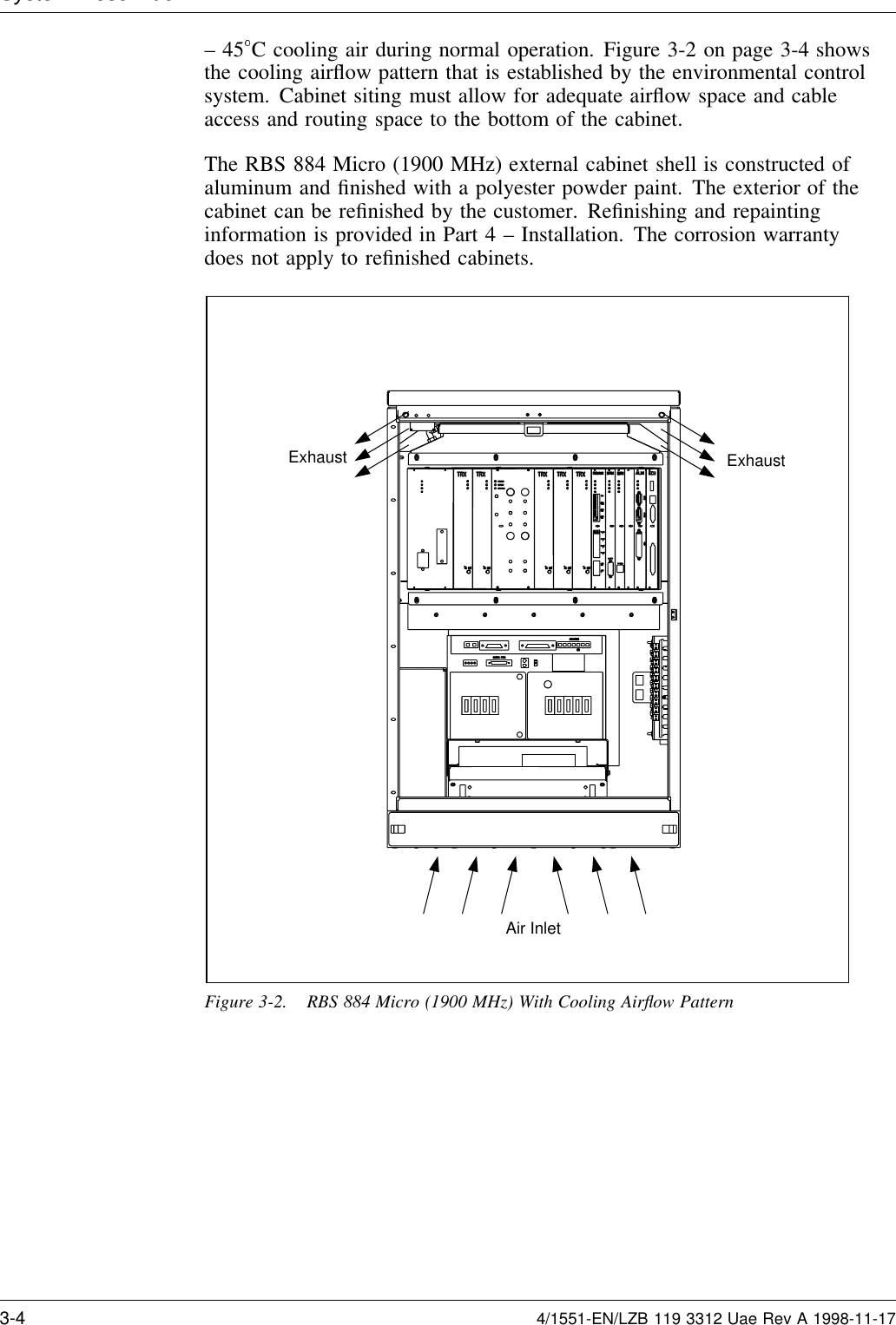
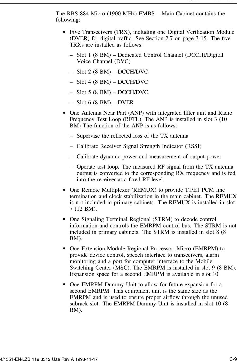
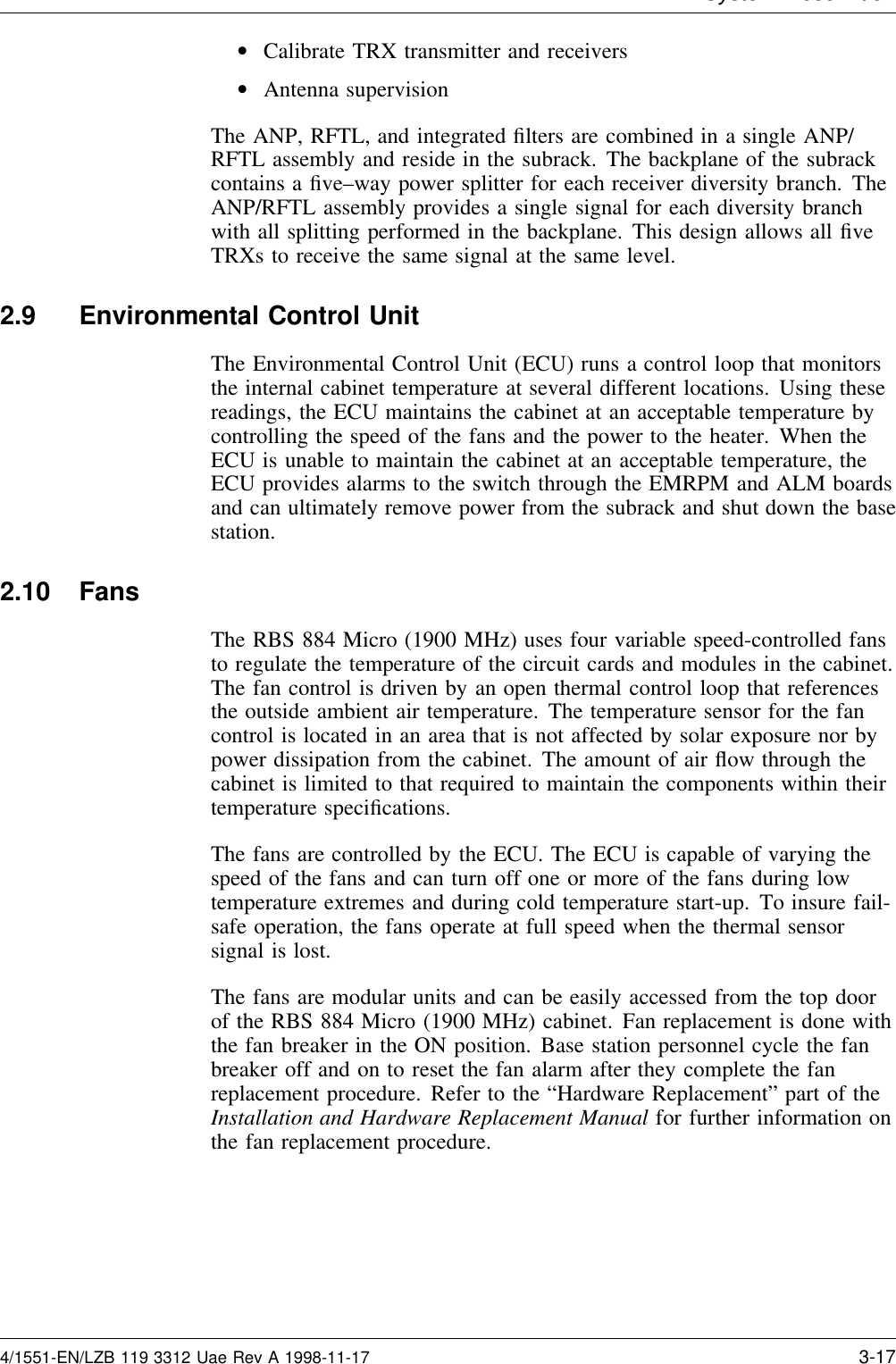
![Installation2. Use the torque wrench with the Torx TX10 to loosen the top andbottom screws on the front of the REMUX unit.Note: Do not touch any components or connector pins ona circuit board.3. Remove the REMUX unit from the cabinet using the extractor toolas shown in Figure 4-20 on page 4-40. Save the extractor hole plugand replace plug after installing the REMUX unit.4. Locate the eight-pole DIP switch at the top front of the REMUX unit.5. Set the unit to the PCM line impedance by setting the switches asshown in Figure 4-22 on page 4-42. The line impedance can be foundin the Configuration Data in the Site Installation Documentation.12345678ON10Top12345678ONFront Line Impedance Switch Settings (1-8)75 ohm (E1) 0111 1101100 ohm (T1) 1011 1110120 ohm (E1) 0000 0000REMUX BoardsROF 367 211/3ROF 367 211/1ROF 367 211/3PCM Line ImpedanceNote: This example shows the REMUX set for 100 ohm line impedance (T1)Figure 4-22. Setting the PCM Line Impedance6. Locate the 32-pole DIP switch at the bottom of the REMUX unit.Note: When a DIP switch is in its lower position (withthe REMUX board oriented as shown in Figure4-22 on page 4-42), the value is 0 (zero).7. Check with the Configuration Data in the Site InstallationDocumentation to determine whether the settings for the PCMPrimary line are decided by the length, attenuation, or impedance ofthe line. Set the switches for the appropriate use as follows:•If line length is used (T1 Short Haul), see Figure 4-23 onpage 4-43.•If impedance is used (for E1 transmission, and T1 FederalCommunications Commission [FCC] Part 68, Option A), seeFigure 4-24 on page 4-43.Note: For distances exceeding 40 meters, customersupplied CSU should be used.4-42 1/1551-EN/LZB 119 3312 Uae Rev A 1998-11-17](https://usermanual.wiki/HARRIS/KRC121106-1.PDF-instruction-manual/User-Guide-15224-Page-84.png)