HARRIS KRC121106-1 User Manual PubTeX output 1998 10 06 2121
HARRIS CORPORATION PubTeX output 1998 10 06 2121
HARRIS >
Contents
- 1. Instruction maintenance manual
- 2. PDF instruction manual
Instruction maintenance manual
RBS 884 Micro (1900 MHz) Installation and
Hardware Replacement Manual
EN/LZB 119 3312 PA4 1998-10-05 © Ericsson Radio Systems AB 1998 All Rights Reserved

The contents of this document are subject to revision without notice due to
continued progress in methodology, design, and manufacturing.
Ericsson shall have no liability for any error or damages of any kind resulting
from the use of this document.
i00 152-EN/LZB 119 3312 Uae Rev PA4 1998-10-05

Table of Contents
Part 1 Introduction . ..................... 1-1
1 Revision Information . . . ............ 1-1
2 About This Manual ................ 1-1
3 Conventions Used in the Manual . ........ 1-2
Part 2 General Product Information . . ............ 2-1
1 Introduction . . ................. 2-3
2 Features . . . ................. 2-3
3 Product Lines . ................. 2-4
4 Architecture . . ................. 2-6
Part 3 System Description . ................. 3-1
1 Introduction . . ................. 3-3
2 RBS 884 Micro (1900 MHz) . . . ........ 3-3
3 Installation Configurations ............ 3-18
Part 4 Installation . . ..................... 4-1
1 Introduction . . ................. 4-3
2 Safety Considerations . . ............ 4-3
3 Electrostatic Discharge (ESD) . . . ........ 4-5
4 Tools . ..................... 4-6
5 Site Selection . ................. 4-7
6 Transportation and Storage ............ 4-8
7 Unpacking . . . ................. 4-9
8 Cabinet Installation ................ 4-12
9 Cable and Power Connections . . ........ 4-22
10 Setting the Unit Switches . ............ 4-34
11 External Cable Installation ............ 4-45
12 Site Inventory . ................. 4-53
13 Equipment Power Up . . . ............ 4-54
14 Cold Start-up . ................. 4-57
15 Completing the Installation ............ 4-58
16 LED Indications ................. 4-59
17 Site Expansion . ................. 4-64
18 RBS 884 Micro (1900 MHz) Cabinet Repainting . . 4-83
Part 5 Hardware Replacement ................. 5-1
1 Introduction . . ................. 5-3
2 Safety Considerations . . ............ 5-3
3 Product Handling and Inspection . ........ 5-6
4 General Troubleshooting . ............ 5-6
5 Alarm Troubleshooting . . ............ 5-11
6 RBS Unit Hardware Replacement . ........ 5-14
00 152-EN/LZB 119 3312 Uae Rev PA4 1998-10-05 ii

Contents
Part 6 Glossary of Terms . . . ................ 6-1
Part 7 Acronyms and Abbreviations . . . ........... 7-1
Appendix A Documentation Overview ................ A-1
Appendix B User Feedback . .................... B-1
Appendix C Internal Cables . .................... C-1
Appendix D Conversion Table . . . ................ D-1
iii 00 152-EN/LZB 119 3312 Uae Rev PA4 1998-10-05

Part 1
Introduction
This part describes the information contained in the manual and the
conventions used in its presentation.
1 Revision Information
This is the first issue of the Installation and Hardware Replacement
Manual (IHRM) for Radio Base Station (RBS) 884 Micro (1900 MHz).
2 About This Manual
This manual contains information required to install, troubleshoot, and
maintain the RBS 884 Micro (1900 MHz).
The target audience for the manual is RBS site installation and site
maintenance personnel.
Before the IHRM is used to perform any installation or maintenance
activities at a radio base station site, the following actions must be
completed:
•Telephone transmission facilities must have been made available and
tested
•AC, DC voltage or both must have been made available
•The antenna system must have been installed and tested
•Grounding system available
When the radio base station equipment has been installed and tested using
the information in this manual, it will remain powered up and ready for
integration into the network by personnel at the Mobile Switching Center
(MSC).
The manual is divided into the following parts:
•Introduction – a description of the contents of the manual and how
the manual can be used.
•General Product Information — a description focused on the radio
base station itself in general terms. This means that it describes an
unconfigured base station, not a working Radio Base station (RBS).
0015-EN/LZB 119 3312 Uae Rev PA4 1998-10-05 1-1

Introduction
•System Description – a description of the RBS 884M equipment
hardware and the available configurations.
•Installation – procedures for the installation and powering up of RBS
884M equipment on site.
•Maintenance – procedures for basic troubleshooting and replacement
of faulty items of equipment.
•Glossary of Terms – definitions of key terms used in the manual.
•Acronyms and Abbreviations – expanded versions of all of the
acronyms and abbreviations used in the manual.
•Document Overview (Appendix A) — This appendix provides an
overview of the existing customer manuals for RBS 884, the work
procedures covered by the manuals, and the recommended use of the
manuals.
•User Feedback (Appendix B) — This appendix provides information
on ordering and trouble reporting for the RBS 884 customer manuals.
•Internal Cables (Appendix C) – description of the internal cables
within each RBS cabinet. These cables are installed at the factory.
•Conversion Table (Appendix D) — table for translating some SI
units to American units
Many of the procedures in the manual require site-specific data from the
Site Installation Documentation relating to the particular radio base station
site.
The procedures in the manual are intended to be performed in the order
presented.
3 Conventions Used in the Manual
The first time an acronym or abbreviation appears in the manual, the
expanded form is shown, followed by the acronym or abbreviation in
parentheses, for example, Mobile Switching Center (MSC).
The abbreviated form is shown without parentheses when the expanded
form is not used.
A list of acronyms and abbreviations can be found in Part 8.
Names of documents are referred to in italic typeface, for example, Site
Installation Documentation.
1-2 0015-EN/LZB 119 3312 Uae Rev PA4 1998-10-05

Part 2
General Product Information
1 Introduction . ................. 2-3
2 Features . . . ................. 2-3
3 Product Lines . ................. 2-4
3.1 RBS 884 Macro . ............ 2-4
3.2 RBS 884 Micro . . ............ 2-5
3.3 RBS 884 Compact ............ 2-6
4 Architecture . ................. 2-6
3/1551-EN/LZB 119 3312 Uae Rev PA4 1998-10-05 2-1

General Product Information
2-2 3/1551-EN/LZB 119 3312 Uae Rev PA4 1998-10-05

General Product Information
1 Introduction
The General Product Information provides general information on
unconfigured radio base stations. See Site Engineering Manual for
descriptions of the available working base station configurations and for
information on RBS interfaces (for instance power, transmission, and
antennas).
2 Features
The RBS 884 Series is a series of products in the CMS 8800 family. The
products in the RBS 884 Series are fully featured modular radio base
stations for both the analog AMPS EIA 553 and the digital D-
AMPS EIA IS 136 systems (Advanced Mobile Phone System Electronics
Industry Association 553 system and Digital American Mobile Phone
System Electronics Industry Association Interim Standard 136 system).
A base station in the RBS 884 Series can support one, two, or three
cells. A cell is a defined area covered by one antenna system, and each
cell has one control channel for digital or one for analog, or both. There is
one cell at an omni site, and one to three cells at a sectorized site.
The RBS 884 Series utilizes multi-mode, multi-functional transceivers
(TRX). The same hardware TRX module can be used for analog and
digital voice, control and monitoring purposes.
The hot repair capability, replacement of defective units when power is
still applied, allows repair to be carried out on an RBS in operation during
normal scheduled maintenance visits.
The RBS 884 Series is designed for remote control monitoring allowing
control and fine tuning of all functions and parameters, such as power
output, frequencies, and switching of redundant units from the Mobile
Switching Center (MSC).
A Radio Frequency Test Loop (RFTL) is an optional feature which enables
precise output power settings, Voltage Standing Wave Ratio (VSWR)
alarm and Receive Signal Strength Indicator (RSSI) test measurements.
The device software is stored in non-volatile memory within the RBS, and
the control part software is downloaded from the (MSC), which ensures a
short time to service at power-up.
3/1551-EN/LZB 119 3312 Uae Rev PA4 1998-10-05 2-3
General Product Information
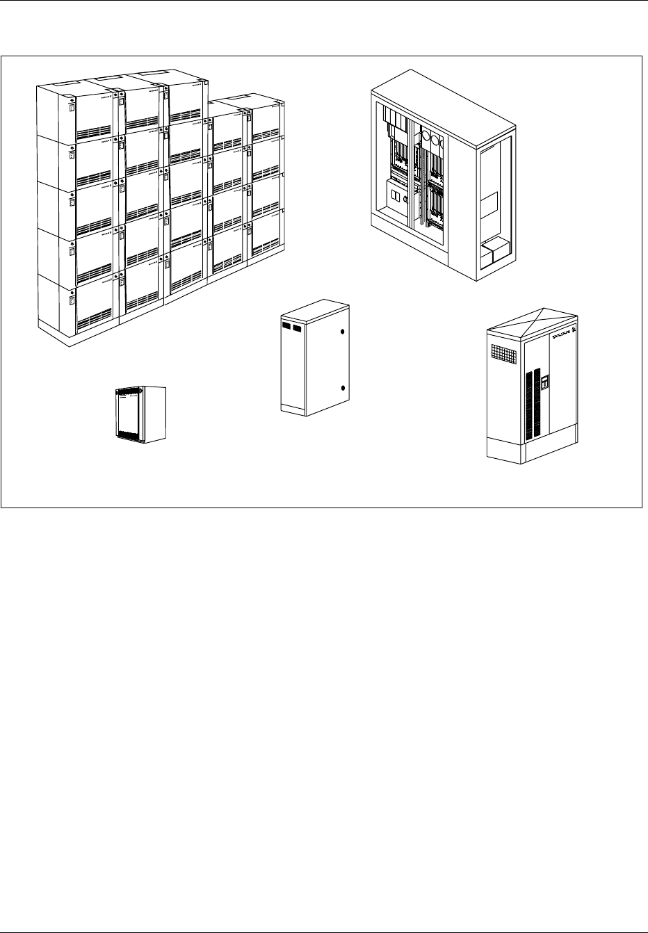
3 Product Lines
RBS 884 RBS 884
RBS 884
RBS 884
RBS 884
RBS 884
RBS 884
RBS 884
RBS 884
RBS 884
RBS 884
RBS 884
RBS 884
RBS 884
RBS 884
RBS 884
RBS 884
RBS 884
RBS 884
RBS 884
RBS 884
RBS 884
RBS 884
RBS 884 Macro
RBS 884
RBS 884 Micro 800 RBS 884 Compact
RBS 884 Outdoor
RBS 884 Micro 1900
Figure 2-1. Product Lines in the RBS 884 Series
The RBS 884 Series includes product lines for macro and micro cells.
Note: The maximum number of carriers for each sector stated is the
technical limitation for the defined standard configurations. The
practical usable sector sizes may be limited by the frequency
plan. The capacity of all product lines, with the exception of
the RBS 884 Micro (1900 MHz) is calculated for analog
systems. The capacity of the RBS 884 Micro (1900 MHz) is
calculated for digital systems. See the integration information
in the RBS 884 Operations and Maintenance Manual for
system limitations in digital systems.
3.1 RBS 884 Macro
The macro cell products are intended for normal indoor installations and
are built up on-site with a number of cabinets of uniform size and design.
The RBS 884 Macro 800 MHz supports AMPS and digital D-AMPS.
Operates at 824–894 MHz and provides up to 78 low power or medium
2-4 3/1551-EN/LZB 119 3312 Uae Rev PA4 1998-10-05

General Product Information
power transceivers (3x24 carriers), or up to 96 high power and 6 low
power transceivers (3x32 carriers).
The RBS 884 Macro 1900 MHz supports digital D-AMPS and operates at
1850–1990 MHz (A-, B-, or C-band). It provides up to 48 medium power
transceivers (3x15 carriers).
A special configuration, Self Contained Cell Site (SCCS), providing up to
8 transceivers in three sectors (3x7 carriers) can be installed in an outdoor
container.
The RBS 884 Macro DBC supports digital D-AMPS and is applicable to
frequencies at 806–860 MHz. Up to 39 medium power transceivers (3x12
carriers) can be used in one installation.
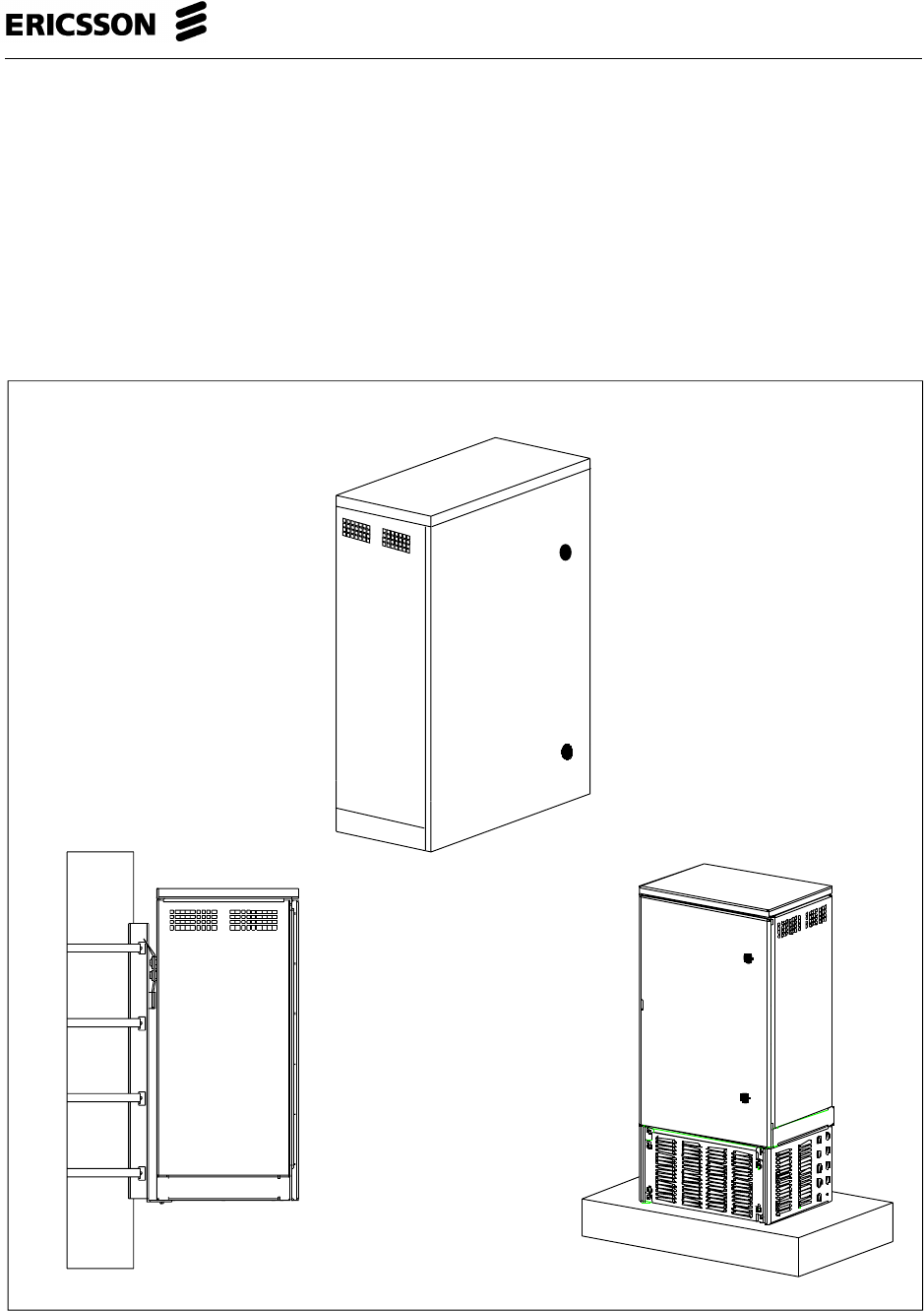
3.2 RBS 884 Micro
The micro cell products can be used wherever local capacity or coverage is
needed.
The RBS 884 Micro 800 MHz is intended for indoor installation, and
typical applications include convention centers, office buildings, parking
areas and tunnels. The RBS 884 Micro comprises one small main cabinet
and two possible expansion cabinets of the same size. It is a completely
functional cell, with drop and insert transmission interface and RF
equipment built-in. Up to 10 1.5W transceivers can be used in one cabinet
(8 carriers). Up to 30 transceivers can be provided with two auxiliary
cabinets (24 carriers). This gives a total capability of up to 23 analog or
68 digital voice channels (71 with E1 PCM links).
The RBS 884 Micro with MCPA (800 MHz)supports analog
AMPS EIA 553 and digital D-AMPS EIA IS 136 and operates at 824–894
MHz. It is a standard RBS 884 Micro (800 MHz) equipped with a Multi
Carrier Power Amplifier (MCPA) for higher output power in one cell. The
MCPA is a separate cabinet, that is mounted below the RBS 884 Micro
(800 MHz) cabinet. Up to three RBS 884 Micro (800 MHz) cabinets and
one MCPA can be mounted in a 19 inch rack cabinet. An RBS 884 Micro
with MCPA (800 MHz) can provide up to 23 analog or 68 digital voice
channels (71 with E1 PCM links) in one cell.
The RBS 884 Micro Outdoor (800 MHz)supports analog AMPS EIA 553
and digital D-AMPS EIA IS 136 and operates at 824–894 MHz. Designed
for outdoor use, it is contained in an all-weather steel enclosure with an
environmentally-controlled interior and can be installed in a wide variety
of locations and climatic zones. The RBS 884 Micro (800 MHz) cabinets
and one MCPA. This means that up to 26 transceivers can be provided
with a total of 24 carriers, which gives a total capacity of up to 23 analog
or 68 digital voice channels (71 with E1 PCM links).
The RBS 884 Micro (1900 MHz) supports digital D-AMPS EIA IS 136
and operates at 1850–1910 MHz. The RBS 884 Micro (1900 MHz) is a
self-contained base station intended primarily for outdoor use. The cabinet
3/1551-EN/LZB 119 3312 Uae Rev PA4 1998-10-05 2-5

General Product Information
is cooled directly with outdoor air, using a combination of variable speed
blowers and a variable power heated to maintain the cabinet air
temperature within equipment operating limits. Typical applications
include ‘hot spot’ areas within mature 1900 MHz networks and areas not
covered by the RBS 884 Macro. The RBS 884 Micro (1900 MHz) is
comprised of one small main cabinet and up to two auxiliary primary
cabinets of the same size. The cabinets can be easily mounted on poles, on
the sides of buildings, on rooftops, or on concrete pads. The RBS 884
Micro is a complete functional cell, with drop and insert transmission
interface and built-in RF equipment. Up to 5 transceivers can be used in
one cabinet providing 4 carriers. Up to 15 transceivers can be used in a
three-cabinet installation providing 3x4 carriers. The three-cabinet
installation allows up to 33 digital traffic channels.
The RBS 884 Micro with MCPA is a standard RBS Micro 884 equipped
with a Multi Carrier Power Amplifier (MCPA) for 30 W normal output
power in one cell. The MCPA is a separate cabinet a bit smaller than the
RBS 884 Micro cabinet. The cabinets can be mounted on a wall, and one
up to three cabinets and one MCPA can be mounted in a standard 19 inch
rack cabinet or Telco rack. An RBS 884 Micro with MCPA can provide
up to 23 analog or 68 digital voice channels (71 with E1 PCM links) in
one cell.
3.3 RBS 884 Compact
The RBS 884 Compact can be compared to the Micro, but is intended for
outdoor installations. It is contained in an all-weather steel cabinet with an
environmentally-controlled interior and can be installed in a wide variety
of locations and climatic zones. The RBS 884 Compact consists of one
primary cabinet and two possible expansion cabinets of the same size. It is
a completely functional cell with drop and insert transmission interface and
RF equipment built-in. Up to 10 low power transceivers can be used in
one cabinet (8 carriers). Up to 30 transceivers can be provided with two
auxiliary cabinets (24 carriers). This gives a total capability of up to 23
analog or 68 digital voice channels (71 with E1 PCM links).
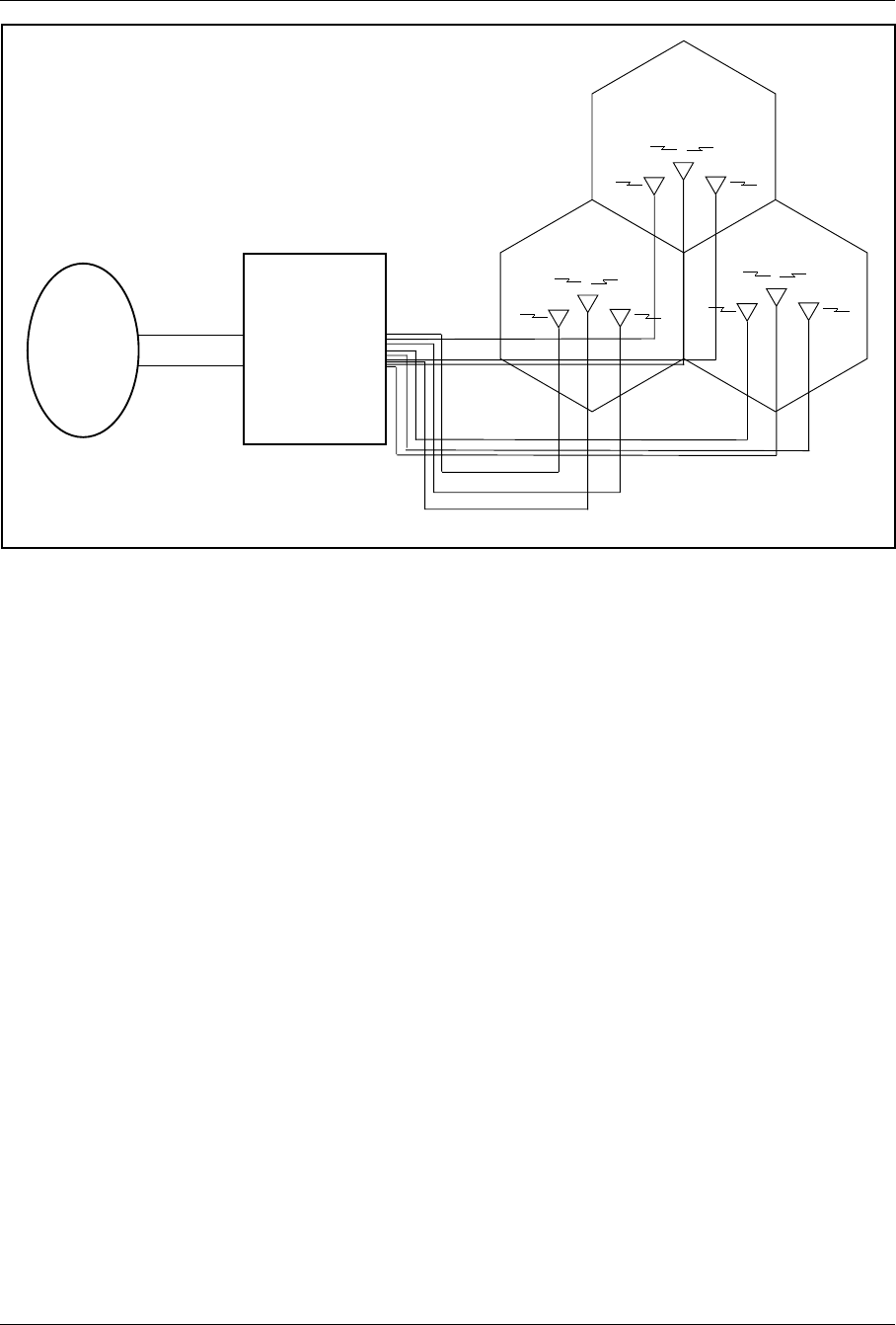
4 Architecture
The radio base station cabinet contains the equipment needed to control
and handle the communication between the MSC and the mobile stations.
The configuration of equipment in a specific system depends on the
number of sectors, the number of voice channels in each sector, the
transmit power, the frequency band, the number and type of antennas, and
if the site is all analog, mixed analog and digital, or all digital. Figure 2-2
on page 2-7 shows the main connections to and from an RBS.
2-6 3/1551-EN/LZB 119 3312 Uae Rev PA4 1998-10-05
General Product Information
PCM LINK 1
PCM LINK 2
TX
RX RX
TX
RX RX
TX
RX RX
Sector A
Sector B Sector C
Antennas
RBS 884
MSC
Figure 2-2. General Overview of MSC – RBS – Antenna Connections (Three-Sector Configuration)
The group switch is responsible for switching calls between subscribers.
The calls may be between two mobile subscribers or between a mobile
subscriber and a subscriber in the public telephone network. In the RBS,
there are several regional processors, controlled by and working with the
central processor. The regional processors control the switch and the
transceivers in the base station. The switch in the base station makes sure
that the speech signals from the MSC are connected to the correct
transceiver. The transceivers generate radio signals emitted by the base
station antenna to the mobile stations. The semipermanent connections are
set up in the MSC. Each TRX handles three digital speech channels, but
uses only one channel on the PCM link.
Figure 2-3 on page 2-8 shows the logical parts of an RBS.
3/1551-EN/LZB 119 3312 Uae Rev PA4 1998-10-05 2-7
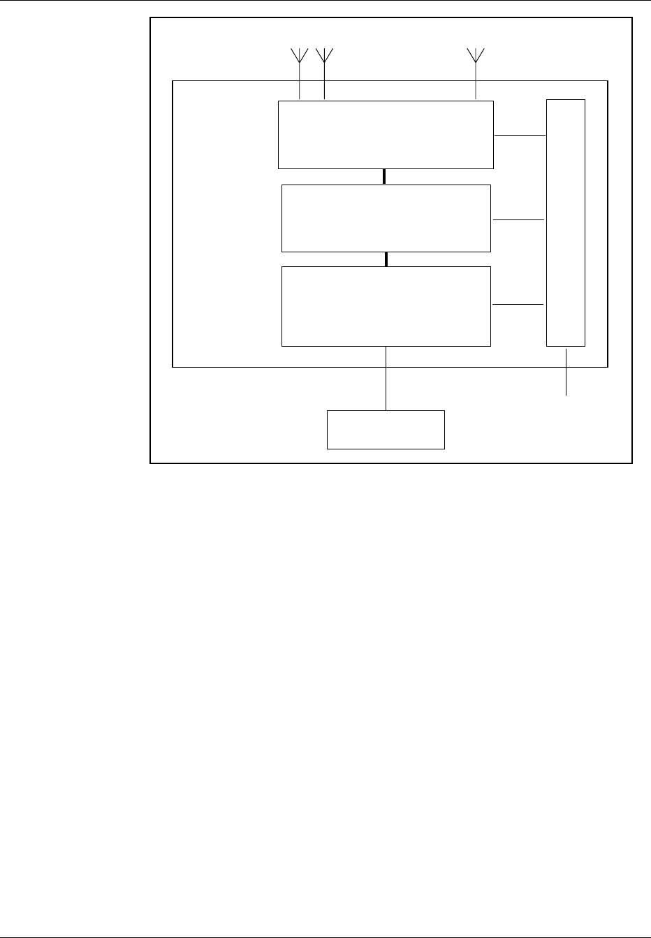
General Product Information
Mobile Switching
Center (MSC)
Control Part
Communicates with MSC and radio
traffic control.
- Remote Multiplexer (terminates PCM link)
- Signal Terminal (decodes control info)
- EMRPs (control TRXs)
Modem Part
Converts speech and data to and from
radio waves.
- Power Splitters for RF input
- Tranceiver Units (TRXs)
Antenna Near Part
- Filter Unit
- Multi-Coupler (Rx amplifier)
- Combiners (one Tx antenna for all carriers)
- Test and calibration
Support Part
Power distribution, fans, external alarms etc.
Rx Tx
T1/E1
PCM Link Power
Radio
Base
Station
(RBS)
Figure 2-3. Block Diagram of a Radio Base Station
•The Control Part (COP) provides communication between the (MSC)
and the (RBS) hardware for radio traffic control and statistical data
gathering. In the RBS 884 Macro the control part consists of Control
and Radio Interface (CRI) cabinet. In Micro and Compact the
Control Part consists of the Remote Multiplexer (REMUX), Signaling
Terminal Remote, Micro (STRM), Extension Module Regional
Processor, Micro (EMRPM), and Connection (CONN) boards.
•The Modem Part (MOP) converts digitized speech and data into
radio frequency signals, hosts channel coding and decoding functions
and performs measurements on radio transmission quality. It is
comprised of transceiver modules (TRXs) in the RBS and voice
coders (TRABs) in the MSC. In the RBS 884 Macro the modem part
consists of the Transceiver cabinet (TCB) and in the RBS 884 Micro
and Compact the MOP consists of TRX boards.
2-8 3/1551-EN/LZB 119 3312 Uae Rev PA4 1998-10-05

General Product Information
•The Antenna Near Part contains components associated with the RF
signal paths, such as auto-tuned combiners, power splitters,
multicouplers, and bandpass filters. The main functions are to
combine multiple TRX output signals to a single Tx antenna, to filter
Tx and Rx signals, to pre-amplify and distribute Rx signals, to
protect TRXs from reflected power, to provide isolation between the
TRXs and to calibrate and supervise the TRXs and associated RF
components. In the RBS 884 Macro the antenna near part consists of
the Antenna Near Part Cabinet (ANPC) and the Auto-tuned
Combiner Cabinet (ATCC). In the RBS 884 Micro (800 MHz) and in
the RBS 884 Compact it consists of a number of boards (RFTL, MC,
COMBFILT and CABCOMB). In the RBS 884 Micro (1900 MHz)
the ANP, bandpath filters, and Radio Frequency Test Loop (RFTL)
are integrated into a single hardware unit. The combined ANP/RFTL/
Filter unit provides RSSI measurement, output power measurement
and calibration, VSWR supervision, and RF path testing.
•The Support Part provides general support, such as power supply and
cooling. The components of this part vary significantly between the
product lines.
3/1551-EN/LZB 119 3312 Uae Rev PA4 1998-10-05 2-9

General Product Information
2-10 3/1551-EN/LZB 119 3312 Uae Rev PA4 1998-10-05

Part 3
System Description
1 Introduction . ................. 3-3
2 RBS 884 Micro (1900 MHz) . . . ........ 3-3
2.1 Cabinet Layout . . ............ 3-3
2.2 Power Distribution Box . . ........ 3-6
2.3 Equipped Microbase Subrack (EMBS) – Main
Cabinet ................. 3-7
2.4 Equipped Microbase Subrack (EMBS) –
Primary Cabinet . ............ 3-11
2.5 Remote Multiplexer (REMUX) . . . .... 3-13
2.6 Extension Module Regional Processor, Micro
(EMRPM) ................ 3-14
2.7 Transceiver (TRX) ............ 3-15
2.8 Antenna Near Part (ANP)/Radio Frequency
Test Loop (RFTL) ............ 3-16
2.9 Environmental Control Unit ........ 3-17
2.10 Fans . . ................. 3-17
2.11 Air Filter ................. 3-18
3 Installation Configurations . . . ........ 3-18
3.1 Limitations ................ 3-18
3.2 Standard Configurations RBS 884 Micro(1900
MHz) . ................. 3-18
4/1551-EN/LZB 119 3312 Uae Rev PA4 1998-10-05 3-1

System Description
3-2 4/1551-EN/LZB 119 3312 Uae Rev PA4 1998-10-05
System Description
1 Introduction
The System Description part of the manual describes the RBS 884 Micro
(1900 MHz) equipment hardware and the available configurations.
2 RBS 884 Micro (1900 MHz)
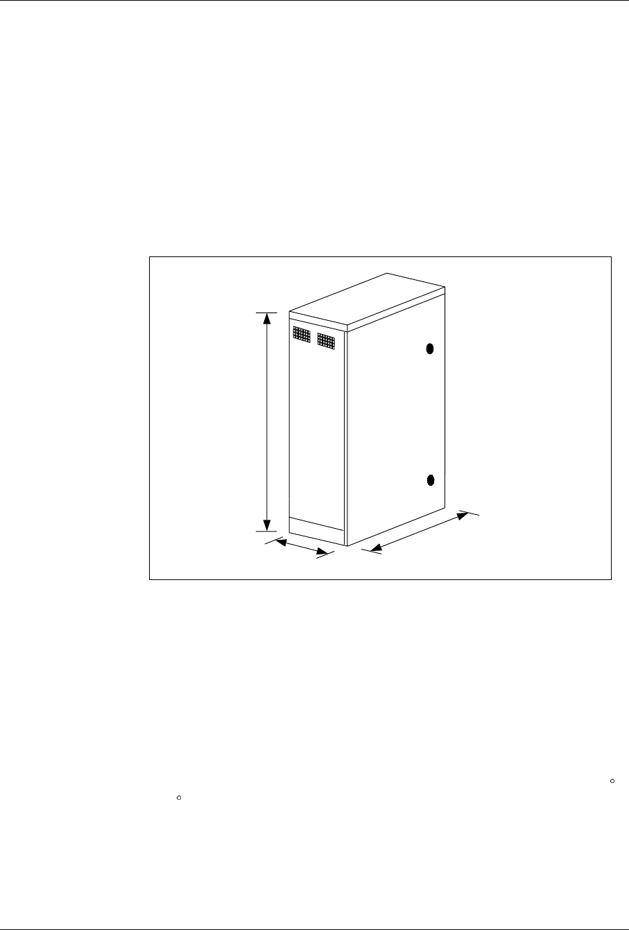
Hardware specifications for the RBS 884 Micro (1900 MHz) are described
in the following section. Figure 3-1 on page 3-3 is an exterior view of the
cabinet.
95 cm
43 cm 61 cm
Figure 3-1. RBS 884 Micro (1900 MHz) Exterior View of Cabinet
2.1 Cabinet Layout
The RBS 884 Micro (1900 MHz) base station cabinet provides mechanical
support, electrical interconnection, cooling, and environmental protection
for the RBS 884 modules and components. All base station equipment
wiring and cabling is easily accessible from the front of the unit. The
electronic cards and modules plug into the backplanes of the electronics
subrack and the subrack is cooled directly with outside air. The RBS
equipment is protected from the external climatic variations by use of the
environmental control system that supplies the internal modules with 10 C
–45C cooling air during normal operation. Figure 3-2 on page 3-4 shows
the cooling airflow pattern that is established by the environmental control
system. Cabinet siting must allow for adequate airflow space and cable
access and routing space to the bottom of the cabinet.
4/1551-EN/LZB 119 3312 Uae Rev PA4 1998-10-05 3-3
System Description
The RBS 884 Micro (1900 MHz) external cabinet shell is constructed of
aluminum and finished with a polyester powder paint. The exterior of the
cabinet can be refinished by the customer. Refinishing and repainting
information is provided in the Installation and Hardware Replacement
Manual. The corrosion warranty does not apply to refinished cabinets.
Air Inlet
Exhaust Exhaust
Figure 3-2. RBS 884 Micro (1900 MHz) With Cooling Airflow Pattern
The RBS 884 Micro (1900 MHz) is comprised of one main cabinet and up
to two auxiliary primary cabinets, as follows:
•Main Cabinet is used in all configurations. The main cabinet
provides up to four digital TRXs and one Digital Verification
Module (DVER). The four TRXs offer a total of 11 Digital Traffic
Channels (DTCs) and one Dedicated Control Channel (DCCH).
•Auxiliary Primary Cabinet has a dedicated antenna system and is
used to create an additional sector within an omni cell. The auxiliary
primary cabinet provides up to four digital TRXs and one DVER
device. The four TRXs offer a total of 11 DTCs and one DCCH.
The primary cabinet requires an EMRPM transmission link
connection to the main cabinet.
3-4 4/1551-EN/LZB 119 3312 Uae Rev PA4 1998-10-05

System Description
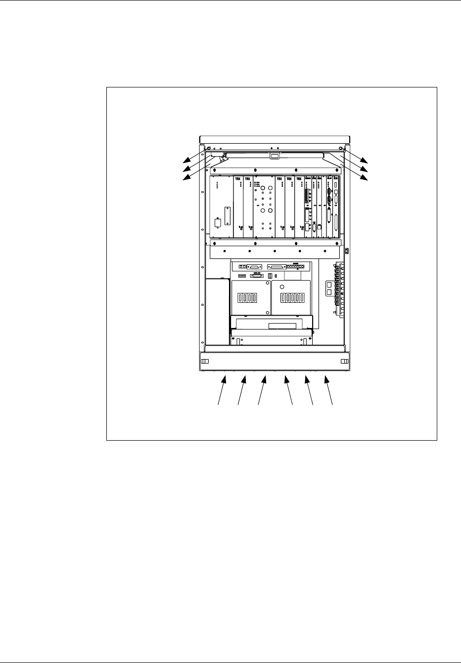
The RBS 884 Micro (1900 MHz) main cabinet contains the following (See
Figure 3-3 on page 3-6):
•Power Distribution Box
•Equipped Microbase Subrack (EMBS)
– Antenna Near Part (ANP) includes the integrated filter unit and
the Radio Frequency Test Loop (RFTL)
– Power Supply Unit (PSU)
– Remote Multiplexer (REMUX)
– Environmental Control Unit (ECU)
– Transceivers (5) (TRX), including 1 Digital Verification Module
(DVER)
– Extension Module Regional Processor, Micro (EMRPM)
– Dummy EMRPM or Blank Module
– Signaling Terminal Regional, Micro (STRM)
– Alarm Board (ALM)
•Fans (4)
•Heater
•AC surge suppressor
•Backup batteries
•Heater for backup batteries
•PCM surge suppressor units (primary and secondary)
•Antenna connector plate or I/O plate with integral quarter wave
shorting stubs for lightning protection
•Optional air filter
4/1551-EN/LZB 119 3312 Uae Rev PA4 1998-10-05 3-5
System Description
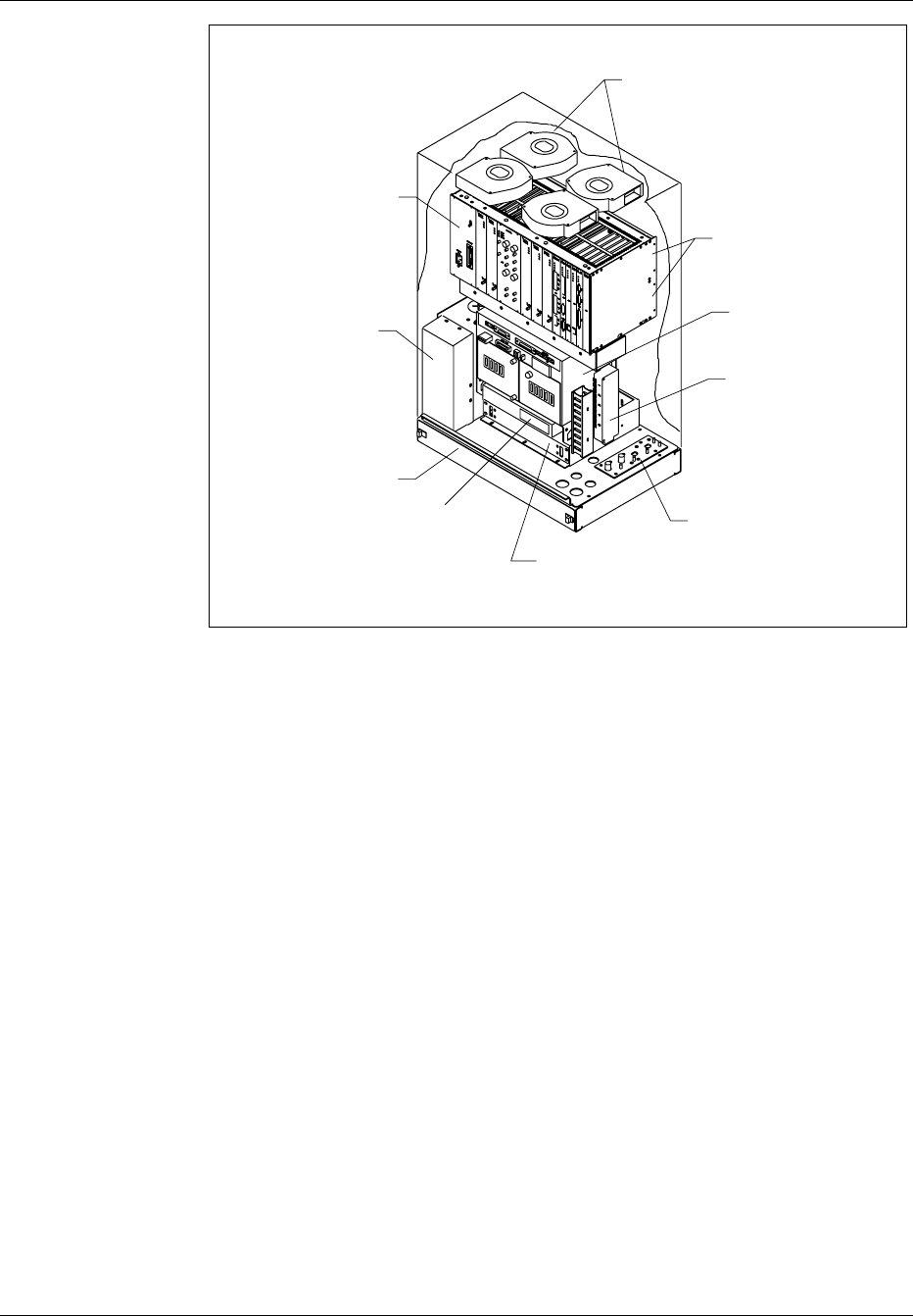
Subrack
with Plug-In
Modules
Battery
Compartment
(2 Batteries)
Fan Units (4)
Backplanes
AC/DC
Power
Air Filter
Access Panel
Heater
Ground Plate
Primary T1
Surge
Suppressor
Secondary T1
Surge
Suppressor
Figure 3-3. RBS 884 Micro (1900 MHz) Fully-Equipped Cabinet
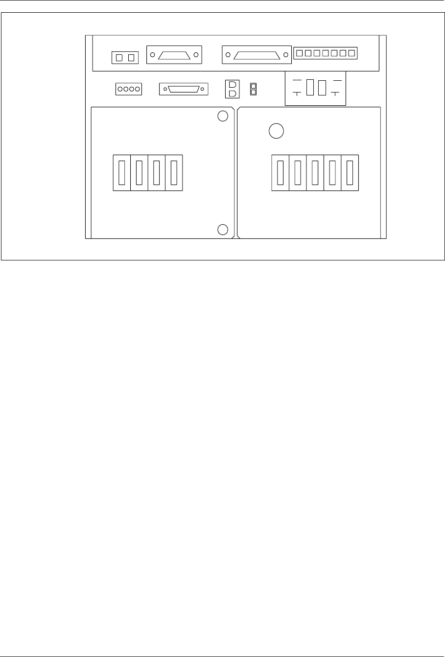
2.2 Power Distribution Box
The power distribution box supplies the RBS equipment with the AC and
DC supply voltages. See Figure 3-4 on page 3-7
The power distribution box contains the following:
3-6 4/1551-EN/LZB 119 3312 Uae Rev PA4 1998-10-05
System Description
ALM CABLE ECU CABLE
SUBRK PWR
FAN PWR CSU
SENSORS
AC
CONNECTED
MAIN PSU MAIN
HTR BAT
HTR GFI
OUTLET
BAT ECU CSU FANS
BAT COMP
BAT
ALM DOOR
ALM
ON
OFF
Figure 3-4. RBS 884 Micro (1900 MHz) Power Distribution Box Front Panel
•DC and alarms distribution panel
•DC and AC breakers
•AC mains
•AC surge connection
•Control board with connectors to temperature sensors, alarms, and
the Environmental Control Unit (ECU)
The RBS 884 Micro (1900 MHz) is designed with service breakers to
allow for replacement of the heaters and batteries while the base station
remains powered. The breakers also provide over-current protection. One
main breaker removes power from the entire cabinet.
2.3 Equipped Microbase Subrack (EMBS) – Main Cabinet
The EMBS – Main Cabinet contains the RBS 884 Micro (1900 MHz)
equipment units described in this section. Figure 3-5 on page 3-8 shows
the main cabinet equipment units in their allocated positions. Variable-
speed fans are located in the top of the cabinet and the resulting air flow is
dimensioned to handle a fully-equipped cabinet. The equipment units and
fans are environmentally sealed to protect circuit board traces and
components from direct exposure to outside cooling air.
4/1551-EN/LZB 119 3312 Uae Rev PA4 1998-10-05 3-7
System Description
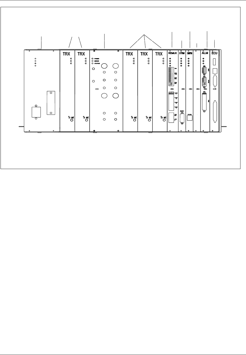
12 354786 9 11 12 13
Power
Supply
Unit TRX
ANP/RFTL
TRX
REMUX
STRM
EMRPM
BLANK
PANEL
ALM
ECU
Figure 3-5. RBS 884 Micro (1900 MHz) EMBS Front Panel — Main Cabinet
The equipment units installed in the cabinet are allocated numbered slots,
(slot No.1 to slot No. 13) from left to right, and are dimensioned using
Building Modules (for example, BM = 1/10 in = 2.54 mm) as the unit of
measurement.
3-8 4/1551-EN/LZB 119 3312 Uae Rev PA4 1998-10-05

System Description
The RBS 884 Micro (1900 MHz) EMBS – Main Cabinet contains the
following:
•Five Transceivers (TRX), including one Digital Verification Module
(DVER) for digital traffic. See Section 2.7 on page 3-15. The five
TRXs are installed as follows:
– Slot 1 (8 BM) – Dedicated Control Channel (DCCH)/Digital
Voice Channel (DVC)
– Slot 2 (8 BM) – DCCH/DVC
– Slot 4 (8 BM) – DCCH/DVC
– Slot 5 (8 BM) – DCCH/DVC
– Slot 6 (8 BM) – DVER
•One Antenna Near Part (ANP) with integrated filter unit and Radio
Frequency Test Loop (RFTL). The ANP is installed in slot 3 (10
BM) The function of the ANP is as follows:
– Supervision of the reflected loss of the TX antenna
– Calibration of Receiver Signal Strength Indicator (RSSI)
– Calibration of dynamic power and measurement of output power
– Operation of test loop. The measured RF signal from the TX
antenna output is converted to the corresponding RX frequency
and is fed into the receiver at a fixed RF level.
•One Remote Multiplexer (REMUX) - provides T1/E1 PCM line
termination and clock stabilization in the main cabinet. The REMUX
is not included in primary cabinets. The REMUX is installed in slot
7 (12 BM).
•One Signaling Terminal Regional (STRM) - decodes control
information and controls the EMRPM control bus. The STRM is not
included in primary cabinets. The STRM is installed in slot 8 (8
BM).
•One Extension Module Regional Processor, Micro (EMRPM) -
provides device control, speech interface to transceivers, alarm
monitoring and a port for computer interface to the Mobile
Switching Center (MSC). The EMRPM is installed in slot 9 (8 BM).
Expansion space for a second EMRPM is available in slot 10.
•One EMRPM Dummy Unit - allows for future expansion for a second
EMRPM. This equipment unit is the same size as the EMRPM and
is used to ensure proper airflow through the unused subrack slot. The
EMRPM Dummy Unit is installed in slot 10 (8 BM).
4/1551-EN/LZB 119 3312 Uae Rev PA4 1998-10-05 3-9

System Description
•One Alarm unit (ALM) – provides maximum connection of 32
external alarms. External alarms are alarms for both internal and
external equipment that are defined as external alarms on the ALM
board. There are no user defined alarms. The ALM is installed in
slot 11 (10 BM).
•One Environment Control Unit (ECU) – controls temperature
regulation inside the cabinet and provides alarms to the TRXs and
the ALM board. The ECU is installed in slot 12 (10 BM).
Note: Unused TRX slots must be equipped with dummy TRXs or
Radio Matching Units (RMUs). Other unused slots must have
an equipment unit (a blank panel along with a dummy board)
to assure proper airflow and electromagnetic shielding.
See Table 3-1 on page 3-10 for the complete EMBS main cabinet
configuration.
Table 3-1. EMBS Configuration for RBS 884 Micro (1900 MHz) Main Cabinet
Slot Name Explanation Comments
1-2 TRX Transceiver The TRXs act as digital voice/control channels.
Slot 1 is recommended for the control channel
TRX.
3ANP/RFTL Antenna Near Part/
Radio Frequency
Test Loop
The ANP provides transmit (TX) and receive
(RX) filtering, low-noise amplifying and RFTL
functionality.
4-5 TRX Transceiver The TRXs act as digital voice/control channels.
TRX slots that are not in use, must be equipped
with a dummy TRX or RMU.
6TRX Transceiver with
digital verification
functionality
The TRX in slot 6 is used as a Personal
Communications Services (PCS) or DVER for
uplink measurements.
7REMUX Remote Multiplexer The REMUX provides T1/E1 PCM line
termination and clock stabilization in the main
cabinet.
8STRM Signaling Terminal
Regional Micro
The STRM decodes control information and
controls the EMRPM.
9EMRPM Extension Module
Regional Processor
Micro
The EMRPM controls the TRXs as well as the
REMUX, the ANP/RFTL, and the ALM.
10 Blank
Module
Dummy EMRPM The Blank Module or equipment unit allows for
future expansion for a second EMRPM. This
equipment unit is the same size as the EMRPM
and is used to ensure proper airflow through the
unused subrack slot.
3-10 4/1551-EN/LZB 119 3312 Uae Rev PA4 1998-10-05
System Description
Table 3-1. EMBS Configuration for RBS 884 Micro (1900 MHz) Main Cabinet (Continued)
Slot Name Explanation Comments
11 ALM Alarm The ALM collects internal and external
equipment alarms.
12 ECU Environmental
Control Unit
The ECU controls temperature regulation inside
the cabinet. The ECU also provides alarms to
the TRXs and the ALM board for fan and heater
failures.
2.4 Equipped Microbase Subrack (EMBS) – Primary Cabinet
The EMBS – Primary Cabinet contains the RBS equipment units described
in this section. Figure 3-6 on page 3-11 shows the primary cabinet units in
their allocated positions. Variable-speed fans are located in the top of the
cabinet and the resulting air flow is dimensioned to handle a
fully-equipped cabinet.
The RBS equipment units and fans are environmentally sealed to protect
circuit board traces and components from direct exposure to outside
cooling air.
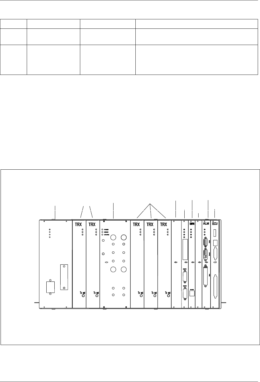
12 354786 9 11 12 13
Power
Supply
Unit TRX ANP/RFTL TRX
CONN
EMRPM
BLANK
PANEL
ALM
ECU
BLANK
PANEL
Figure 3-6. RBS 884 Micro (1900 MHz) EMBS Front Panel — Primary Cabinet
4/1551-EN/LZB 119 3312 Uae Rev PA4 1998-10-05 3-11

System Description
The RBS 884 Micro (1900 MHz) EMBS – Primary Cabinet contains the
following:
•Five Transceivers (TRX), including one Digital Verification Module
(DVER) for digital traffic. See Section 2.7 on page 3-15. The five
TRXs are installed as follows:
– Slot 1 (8 BM) – DCCH/DVC
– Slot 2 (8 BM) – DCCH/DVC
– Slot 4 (8 BM) – DCCH/DVC
– Slot 5 (8 BM) – DCCH/DVC
– Slot 6 (8 BM) – DVER
•One ANP/RFTL with integrated filter unit. The ANP/RFTL is
installed in slot 3 (10 BM).
•One Blank equipment unit or Dummy REMUX. The Dummy
REMUX is installed in slot 7 (8 BM).
•One Connector (CONN) Unit - relays signals from the REMUX and
STRM units in the main cabinet to the other units in the primary
cabinet. The CONN is installed in slot 8 (8 BM).
•One Extension Module Regional Processor, Micro (EMRPM) -
controls the TRX slots 1, 2, 4, 5, and 6. The EMRPM is installed in
slot 9 (8 BM)
•One EMRPM Dummy Unit- allows for future expansion for a second
EMRPM. This equipment unit is the same size as the EMRPM and
is used to ensure proper airflow through the unused subrack slot. The
EMRPM Dummy Unit is installed in slot No.10 (8 BM).
•One Alarm Unit (ALM) — provides maximum connection of 32
external alarms. External alarms are alarms for both internal and
external equipment that are defined as external alarms on the ALM
board. There are no user defined alarms. The ALM is installed in
slot 11 (10 BM).
•1 Environment Control Unit (ECU). The ECU is installed in slot 12
(10 BM).
Note: Unused TRX slots must be equipped with dummy TRXs or
Radio Matching Units (RMU). Other unused slots must have
an equipment unit (a blank panel along with a dummy board)
to assure proper airflow and electromagnetic shielding.
See Table 3-2 on page 3-13 for the complete EMBS primary cabinet
configuration.
3-12 4/1551-EN/LZB 119 3312 Uae Rev PA4 1998-10-05

System Description
Table 3-2. EMBS Configuration for RBS 884 Micro (1900 MHz) Primary Cabinet
Slot Name Explanation Comments
1-2 TRX Transmit TRX The TRXs act as digital voice/control channels.
Slot 1 is recommended for the control channel
TRX.
3ANP/RFTL Antenna Near Part/Radio
Frequency Test Loop
The ANP provides transmit (TX) and receive
(RX) filtering, low-noise amplifier and RFTL
functionality.
4-5 TRX Transceiver The TRXs act as digital voice/control channels.
TRX slots which are not in use, must be
equipped with a dummy TRX or RMU.
6 TRX Transceiver with digital
verification functionality
The TRX in slot 6 is used as a Personal
Communication Services (PCS) or DVER for
uplink measurements.
7Blank
module
Dummy TRX The dummy TRX or RMU is used to ensure
proper airflow through the unused subrack slot.
8CONN Connection Board The CONN board passes TRX signals to the
backplane.
9EMRPM Extension Module
Regional Processor Micro
The EMRPM controls the TRXs as well as the
REMUX, the ANP/RFTL, and the ALM units.
10 Blank
Module
Dummy EMRPM The Blank Module or equipment unit allows for
future expansion for a second EMRPM. This
equipment unit is the same size as the EMRPM
and is used to ensure proper airflow through the
unused subrack slot.
11 ALM Alarm The ALM collects internal and external
equipment alarms.
12 ECU Environmental Control
Unit
The ECU controls temperature regulation inside
the cabinet. The ECU also provides alarms to
the TRXs and the ALM board for fan and heater
failures.
2.5 Remote Multiplexer (REMUX)
The RBS 884 Micro (1900 MHz) contains a T1/E1 transmission unit
(REMUX) for a 24 channel or 32 channel PCM link with the MSC. The
incoming PCM is connected to the PCM Primary (Prim) connector on the
REMUX.
One REMUX unit is installed in slot No. 8 in the main cabinet.
For distances of greater than 200 meters, a customer-supplied Channel
Service Unit (CSU) can be mounted on the shelf above the main cabinet
heater.
Table 3-3 on page 3-14 shows the available REMUX types for T1 and E1
systems.
4/1551-EN/LZB 119 3312 Uae Rev PA4 1998-10-05 3-13

System Description
Table 3-3. PCM System - REMUX
PCM System Type Distance to Nearest Active Device (For
Instance, CSU or Repeater) REMUX
T1 Short Haul
without external
Channel Service
Unit CSU
<200 m REMUX 24
T1 Long Haul
with external
CSU
<1800 m REMUX 24
E1 Short Haul <200 m REMUX 32SH
The REMUX switches are preset at the factory according to the
predetermined transmission requirements of the RBS 884 Micro (1900
MHz) site supplied by the site engineer.
The site engineer insures that the installer has access to documented
transmission specifications for the RBS 884 Micro (1900 MHz) site. It is
vital that the site engineer records all PCM line and switching information
in the site installation documentation.
2.6 Extension Module Regional Processor, Micro (EMRPM)
Each RBS 884 Micro (1900 MHz) cabinet contains one EMRPM unit
which controls TRX traffic. An extra slot is provided for possible future
expansion for a second EMRPM unit to share the traffic load. Ten devices
can be connected to each EMRPM unit with TLINK connections. These
are numbered TLINK 1 to TLINK 10.
The load capacity of the EMRPM allows up to four of the DVC TLINK
connections for TRXs. The EMRPM is assigned to control the REMUX
and the RFTL.
The incoming time slots are connected in a fixed pattern, as shown in
Table 3-4 on page 3-14.
Table 3-4. RBS 884 Micro (1900 MHz) EMRPM 1
EMRPM TLINK Cabinet slot Function
1 1 TRX
2 2 TRX
3 4 TRX
4 5 TRX
6 6 DVER
7 11 ALM
9 3 ANP
10 7 REMUX
3-14 4/1551-EN/LZB 119 3312 Uae Rev PA4 1998-10-05

System Description
The addresses of the EMRPM are set using a DIP switch on the unit. No
address plug is required. The address is dependent upon the configuration
of the RBS site and number of cabinets used.
The site installation documentation shows how the switches are to be set
for a specific site.
A computer can be connected to the TW/DEB port at the front of the
EMRPM unit. The interface has the same function as the V24–B3 unit.
2.7 Transceiver (TRX)
The transceiver (TRX) transmits and receives radio signals to and from
mobile stations.
A TRX unit can be remotely configured to support any of the following
channel functions:
•Digital Voice Channel (DVC) – transmits and receives
•Digital Control Channel DCCH) – transmits and receives
•Digital Verification (DVER) Channel – receives only
The selection of transceiver channel function is under software control at
the Mobile Switching Center (MSC). The first time slot may be used for
DCCH and the remaining two time slots for DVCs, or all three time slots
may be used for DVCs.
The TRX provides 33.3 dBm (2.1 W) per carrier at the ANP for the two-
antenna configuration and 36.8 dBm (4.8 W) per carrier at the ANP for the
four-antenna configuration. The dynamic range is 20 dB with 0.2–dB
resolution.
The TRX includes all functionality needed for one RF channel, such as:
•Channel coding and decoding
•Modulation and demodulation
•Power amplification
•Power regulation
•Synchronization
•Diversity combining
•Measurements on received radio signal
•Verification processing (when configured as DVER)
The maximum output power for each TRX is 13.5 W. Note that digital
speech coding takes place in the voice coder units in the MSC and not in
the TRXs. There are four TRXs (carriers) for each antenna system, which
provides 11 digital voice paths per sector.
4/1551-EN/LZB 119 3312 Uae Rev PA4 1998-10-05 3-15

System Description
Table 3-5 on page 3-16 shows the allocation slots for TRX units in
cabinets that are not fully equipped. In the following table, the TRX
positions shown in bold (X) represent factory installed units. All empty
slots must contain an RMU.
Note: The term transceiver or TRX is used in this document to refer
to the hardware unit itself and does not reflect the functionality
of the unit. Subrack position 6 must be equipped with a TRX
that functions as a receiver or Digital Verification Module
(DVER).
Table 3-5. RBS 884 Micro (1900 MHz) TRX Unit Installation – Cabinet Not Fully
Equipped
TRX slot position in cabinet
No. of TRX 1 2 4 5 6
(DVER)
X X X
3X X X
X X X X
X X X X
4
XXXX
5X X X X X
The maximum speech traffic capacity for a three cabinet configuration is
33 digital voice channels for both the American standard (T1 environment)
and the International standard (E1 environment).
In cascaded configurations one PCM time slot for speech is lost for each
additional signaling link.
2.8 Antenna Near Part (ANP)/Radio Frequency Test Loop (RFTL)
The combined Antenna Near Part (ANP), Radio Frequency Test Loop
(RFTL), and integrated filter unit provides combining and splitting of RF
signals to each antenna.
The main functions of the ANP/RFTL are as follows:
•Combine the output signal of the TRXs
•Filter TX and RX signals
•Protect the TRXs from high reflected power
•Pre-amplify and distribute RX signals
•Provide isolation between the TRXs
3-16 4/1551-EN/LZB 119 3312 Uae Rev PA4 1998-10-05

System Description
•Calibrate TRX transmitter and receivers
•Antenna supervision
The ANP, RFTL, and integrated filters are combined in a single ANP/
RFTL assembly and reside in the subrack. The backplane of the subrack
contains a five–way power splitter for each receiver diversity branch. The
ANP/RFTL assembly provides a single signal for each diversity branch
with all splitting performed in the backplane. This design allows all five
TRXs to receive the same signal at the same level.
2.9 Environmental Control Unit
The Environmental Control Unit (ECU) runs a control loop that monitors
the internal cabinet temperature at several different locations. Using these
readings, the ECU maintains the cabinet at an acceptable temperature by
controlling the speed of the fans and the power to the heater. When the
ECU is unable to maintain the cabinet at an acceptable temperature, the
ECU provides alarms to the switch through the EMRPM and ALM boards
and can ultimately remove power from the subrack and shut down the base
station.
2.10 Fans
The RBS 884 Micro (1900 MHz) uses four variable speed-controlled fans
to regulate the temperature of the circuit cards and modules in the cabinet.
The fan control is driven by an open thermal control loop that references
the outside ambient air temperature. The temperature sensor for the fan
control is located in an area that is not affected by solar exposure nor by
power dissipation from the cabinet. The amount of air flow through the
cabinet is limited to that required to maintain the components within their
temperature specifications.
The fans are controlled by the ECU. The ECU is capable of varying the
speed of the fans and can turn off one or more of the fans during low
temperature extremes and during cold temperature start-up. To insure fail-
safe operation, the fans operate at full speed when the thermal sensor
signal is lost.
The fans are modular units and can be easily accessed from the top door
of the RBS 884 Micro (1900 MHz) cabinet. Fan replacement is done with
the fan breaker in the ON position. Base station personnel cycle the fan
breaker off and on to reset the fan alarm after they complete the fan
replacement procedure. Refer to the RBS 884 Micro (1900 MHz)
Installation and Hardware Replacement Manual for further information on
the fan replacement procedure.
4/1551-EN/LZB 119 3312 Uae Rev PA4 1998-10-05 3-17

System Description
2.11 Air Filter
The RBS 884 Micro (1900 MHz) cabinet is equipped with a cooling air
intake filter. The lower front panel of the cabinet is removable to gain
access for periodic filter replacement.
3 Installation Configurations
3.1 Limitations
One RBS cabinet can contain up to five transceivers, four of which can be
used for handling speech traffic.
3.2 Standard Configurations RBS 884 Micro(1900 MHz)
The RBS 884 Micro (1900 MHz) cabinets are pre-configured and
assembled at the factory before delivery to the RBS site. It is the
responsibility of the site engineer to dimension the required configuration.
When considering which configuration to choose, the dimensioning of the
transceiver (TRX) units must be done. The RBS 884 Micro (1900 MHz)
can contain as few as three TRX units per cabinet. Additional capacity can
be added later.
The RBS 884 Micro (1900 MHz) product contains a number of cabinet
configurations depending on the following:
•AC power voltage: 110 V 60 Hz or 230 V 50 Hz
•Type of transmission: E1 or T1
•Antenna configuration: 2 or 4 antennas
– Two antenna mounting: cabinet-mounted or external
– Four antenna mounting: external
•Frequency band: AD, DBE, or EFC
•Number of TRXs: 3, 4, or 5 (including 1 Digital Verification
(DVER) unit)
The number of cabinets required at the RBS site can be one, two, or three,
depending on the number of TRX units and sectors determined for that
specific RBS site. The 1900 MHz base station cabinet can be configured to
perform as a main or as a primary cabinet by installing the appropriate
equipment units.
The configuration diagrams in this section show cabinets (main, and
primary), PCM input, AC power input, antenna configurations, and
interconnections between cabinets. The cabinets are shown with maximum
3-18 4/1551-EN/LZB 119 3312 Uae Rev PA4 1998-10-05

System Description
equipment installed. The PCM/TLINK/EMRPM, control, and
synchronization interconnections between cabinets are shown as DATA.
Each cabinet requires a separate electrical AC power input supply.
Table 3-6 on page 3-19 provides a list of the antenna and PCM cable
connection points that appear on the underside of the Mounting Base
Connector Plate.
Table 3-6. Mounting Base Connector Plate – External Cables
External Cable Connector Connector Plate Connection
Antenna TX/RX (1st) ANT - 1
Antenna TX/RX (2nd) ANT- 2
Antenna TX (1st) ANT- 3
Antenna TX (2nd) ANT- 4
PCM PCM - P
The PCM transmission connection from the RBS to the MSC connects
through the PCM lightening protection box that is located below the
subrack in the main cabinet.
Refer to the RF Guidelines for information on reverse isolation and the
output power levels for each configuration.
3.2.1 One-Sector Site
The following cabinet configurations are available for the RBS 884 Micro
(1900 MHz) one-sector site.
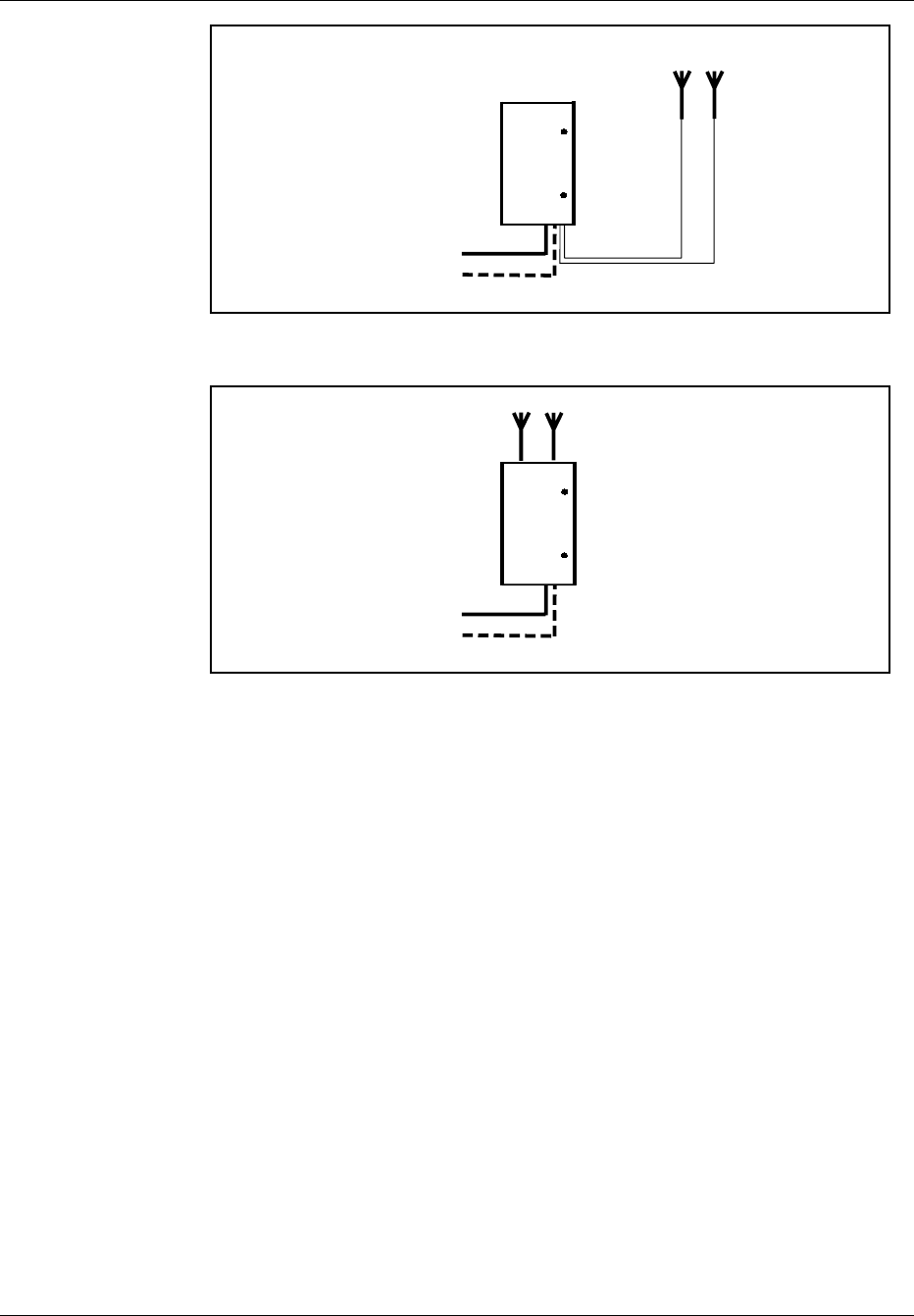
3.2.1.1 Single Cabinet - 2 Duplex Filters, 2 TX/RX Antennas
Figure 3-7 on page 3-20 and Figure 3-8 on page 3-20 show one-sector site
configurations. Both of these configurations have a two-antenna ANP with
hybrid combiners and duplex filters connected to an antenna array of two
TX/RX antennas.
The ANP for both the cabinet-mounted antenna and the external antenna is
offered in the following frequency bands:
•AD
•DBE
•EFC
4/1551-EN/LZB 119 3312 Uae Rev PA4 1998-10-05 3-19
System Description
MAIN
CABINET
AC POWER (110V/230V)
PCM (T1/E1)
●●
TX/RX TX/RX
Two-Antenna
ANP
Figure 3-7. Cabinet Connections, RBS 884 Micro (1900 MHz) One-Sector Site – One
Cabinet – Two TX/RX Antennas
MAIN
CABINET
AC POWER (110V/230V)
PCM (T1/E1)
●●
TX/RX TX/RX
Two-Antenna
ANP
Figure 3-8. Cabinet Connections, RBS 884 Micro (1900 MHz) One-Sector Site – One
Cabinet – Two Fixed Antennas
The Cabinet-Mounted Antenna Kit can be used to mount two fixed
antennas directly on the cabinet for a totally self-contained base station.
Note: Single sector site expansion is possible with the use of shared
antennas and cell overlays, although RF performance may be
compromised.
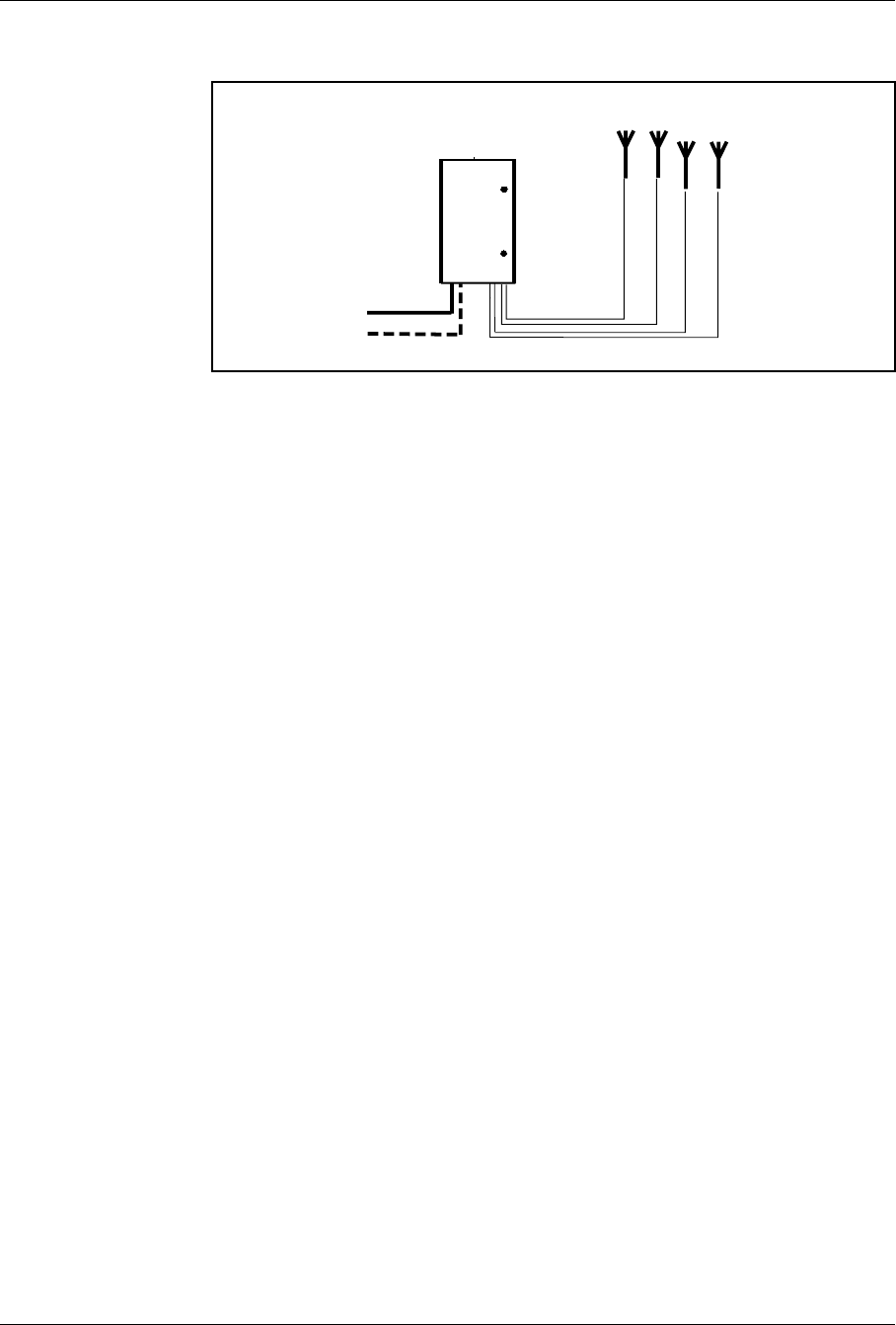
3.2.1.2 Single Cabinet — 4 Antennas (2 TX/RX Antennas and 2 TX-Only Antennas)
Figure 3-9 on page 3-21 shows a one-sector site configuration with a four-
antenna ANP connected to an antenna array of two TX-only antennas and
two TX/RX antennas with duplex filters.
The four-antenna ANP is offered in the following frequency bands:
•AD
•DBE
•EFC
3-20 4/1551-EN/LZB 119 3312 Uae Rev PA4 1998-10-05
System Description
MAIN
CABINET
AC POWER 110V/230V
PCM (T1/E1)
●●
TX TX/RX
●●
TX/RX TX
Four-Antenna
ANP
Figure 3-9. Cabinet Connections, RBS 884 Micro (1900 MHz) One-Sector Site – 1
Cabinet – 4 Antennas
Note: Single sector site expansion is possible with the use of shared
antennas and cell overlays although RF performance may be
compromised.
3.2.2 Two-Sector Site
The following cabinet configurations are available for the RBS 884 Micro
(1900 MHz) two-sector site.
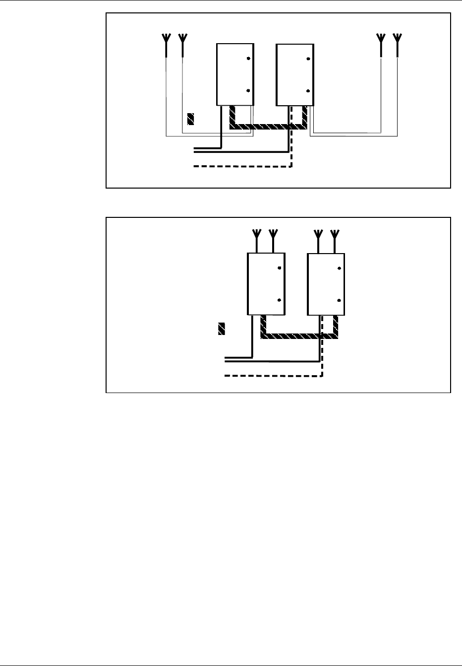
3.2.2.1 Dual Cabinets — 2 TX/RX Antennas
Figure 3-10 on page 3-22 and Figure 3-11 on page 3-22 show two-sector
site configurations with a main and a primary cabinet. Each cabinet has a
two-antenna ANP with hybrid combiner filters and duplex filters connected
to an antenna array of two TX/RX antennas.
The two-antenna ANP for both the cabinet-mounted antenna and the
external antenna is offered in the following frequency bands:
•AD
•DBE
•EFC
4/1551-EN/LZB 119 3312 Uae Rev PA4 1998-10-05 3-21
System Description
PRIMARY
CABINET MAIN
CABINET
AC
POWER (110V/230V)
PCM (T1/E1)
●●
TX/RX TX/RX
DATA
●●
TX/RX
TX/RX
Two-Antenna
ANP
Two-Antenna
ANP
Figure 3-10. Two-Sector Site - 2 Cabinets - 2 TX/RX Antennas
PRIMARY
CABINET MAIN
CABINET
AC
POWER (110V/230V)
PCM (T1/E1)
DATA
●●
●●
TX/RX TX/RX TX/RX TX/RX
Two-Antenna
ANP
Two-Antenna
ANP
Figure 3-11. Cabinet Connections, RBS 884 Micro (1900 MHz) Two-Sector Site – 2
Cabinets – 2 Fixed Antennas
The Cabinet-Mounted Antenna Kit can be used to mount two fixed
antennas on each cabinet for a totally self-contained base station site.
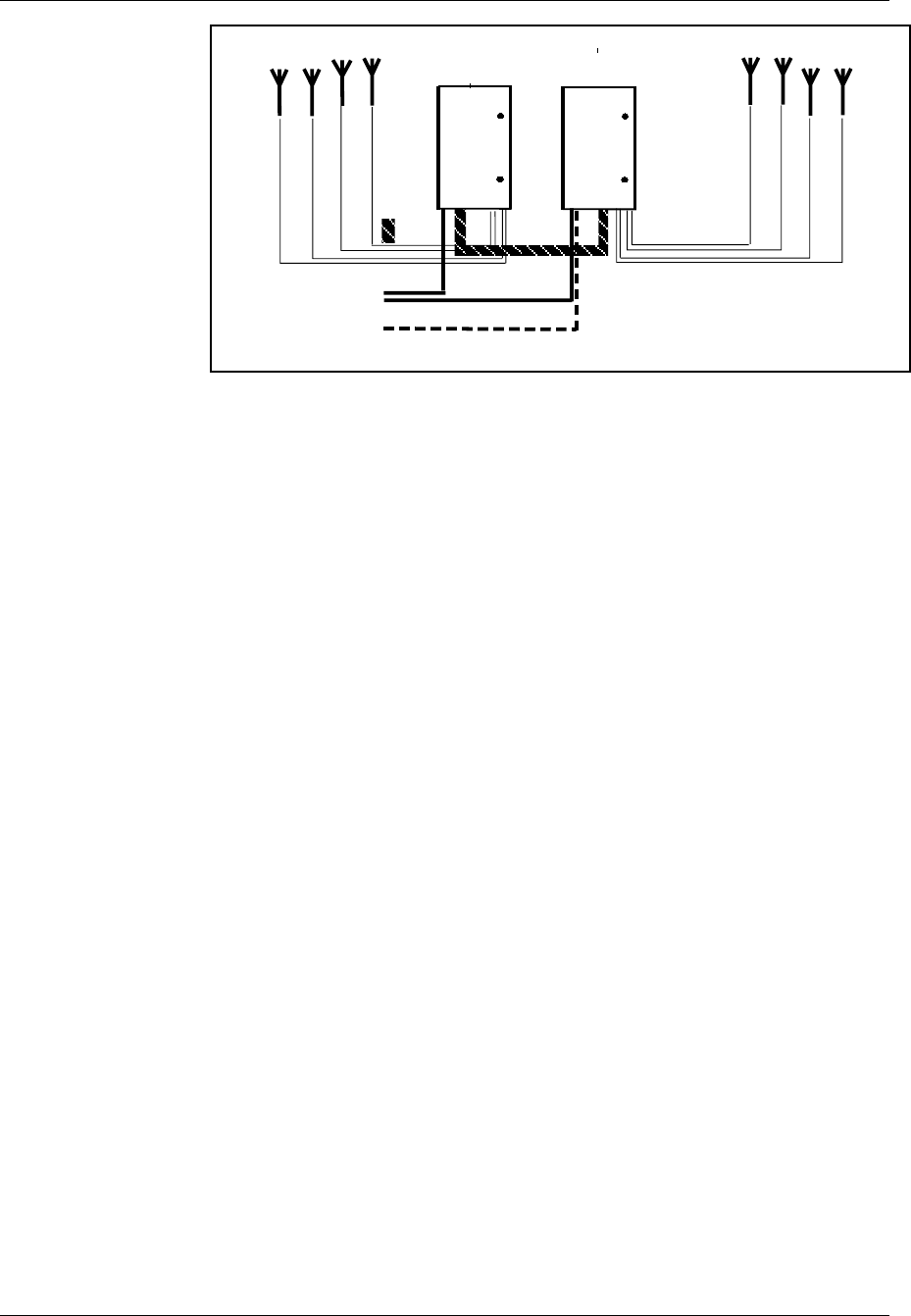
3.2.2.2 Dual Cabinets — 4 Antennas (2 TX/RX Antennas and 2 TX-Only Antennas)
Figure 3-12 on page 3-23 shows a two-sector site configuration with a
main and a primary cabinet. Each cabinet has a four-antenna ANP
connected to an antenna array of two TX-only antennas and two TX/RX
antennas with duplex filters.
The four-antenna ANP is offered in the following frequency bands:
•AD
•DBE
•EFC
3-22 4/1551-EN/LZB 119 3312 Uae Rev PA4 1998-10-05
System Description
PRIMARY
CABINET MAIN
CABINET
AC POWER (110V/230V)
PCM (T1/E1)
DATA
●●
TX TX/RX
●●
TX/RX TX
●
TX
TX/RX
●●
TX/RX
TX
●
Four-Antenna
ANP
Four-Antenna
ANP
Figure 3-12. Two-Sector Site - 2 Cabinets - 4 Antennas
3.2.3 Three-Sector Site
The following cabinet configurations are available for the RBS 884 Micro
(1900 MHz) in a three-sector site.
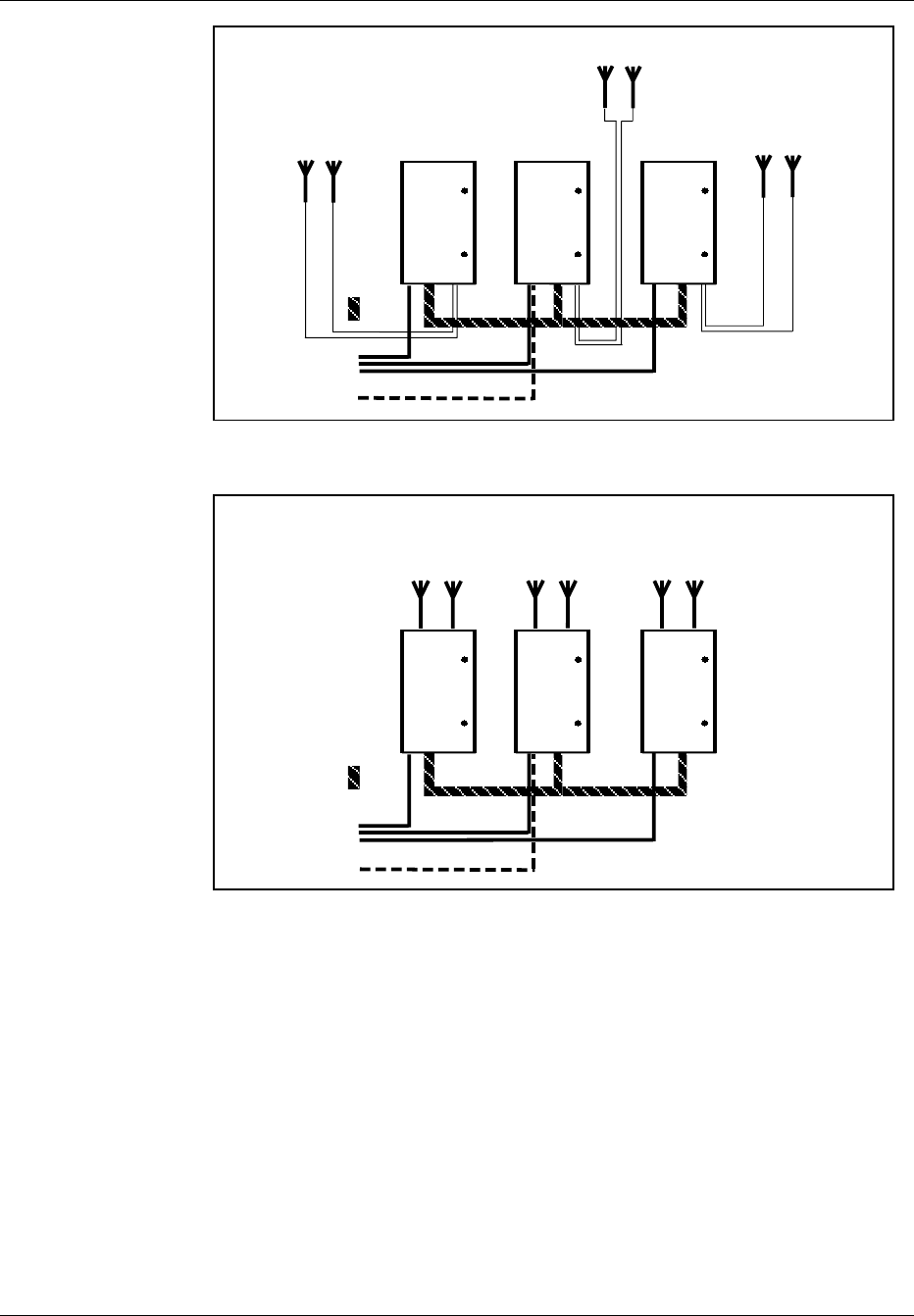
3.2.3.1 Triple Cabinets — 2 TX/RX Antennas
Figure 3-13 on page 3-24 and Figure 3-14 on page 3-24 show three-sector
site configurations with a main and two primary cabinets. Each cabinet has
a two-antenna ANP with hybrid combiner filters and duplex filters
connected to an antenna array of two TX/RX antennas. The primary
cabinets are used to provide additional sectors.
The two-antenna ANP for both the cabinet-mounted antenna and the
external antenna is offered in the following frequency bands:
•AD
•DBE
•EFC
4/1551-EN/LZB 119 3312 Uae Rev PA4 1998-10-05 3-23
System Description
DATA
PRIMARY 1
CABINET MAIN
CABINET PRIMARY 2
CABINET
AC POWER (110V/230V)
PCM (T1/E1)
●●
●●
TX/RX TX/RX
●●
TX/RX TX/RX TX/RX TX/RX
Two-Antenna
ANP
Two-Antenna
ANP
Two-Antenna
ANP
Figure 3-13. Cabinet Connections, RBS 884 Micro (1900 MHz) Three-Sector Site - 3
Cabinets - 2 TX/RX Antennas
DATA
PRIMARY 1
CABINET MAIN
CABINET PRIMARY 2
CABINET
AC POWER (110V/230V)
PCM (T1/E1)
●●
●●
●●
TX/RX TX/RX TX/RX TX/RX TX/RX TX/RX
Two-Antenna
ANP
Two-Antenna
ANP
Two-Antenna
ANP
Figure 3-14. Cabinet Connections, RBS 884 Micro (1900 MHz) Three-Sector Site – 2
Cabinets – 2 Fixed Antennas
The Cabinet-Mounted Antenna Kit can be used to mount two fixed
antennas to each cabinet for a totally self-contained base station site.
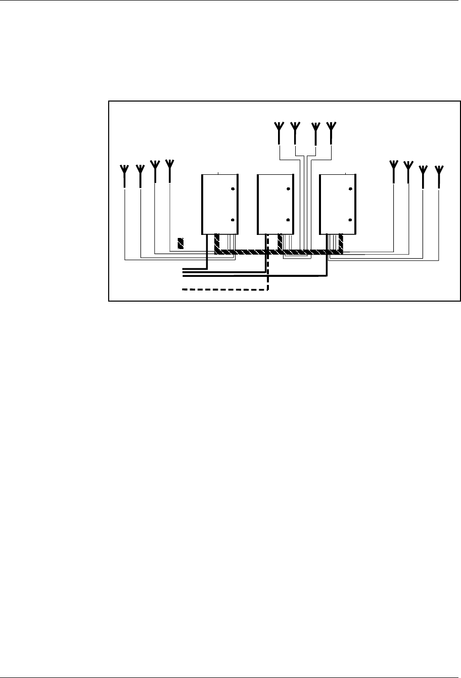
3.2.3.2 Triple Cabinets — 4 Antennas (2 TX/RX Antennas, 2 TX-Only Antennas)
Figure 3-15 on page 3-25 shows a three-sector site configuration with one
main and two primary cabinets. Each cabinet has a four-antenna ANP
connected to an antenna array of two TX-only antennas and two TX/RX
antennas with duplex filters.
3-24 4/1551-EN/LZB 119 3312 Uae Rev PA4 1998-10-05
System Description
The four-antenna ANP is offered in the following frequency bands:
•AD
•DBE
•EFC
PRIMARY 1
CABINET MAIN
CABINET PRIMARY 2
CABINET
AC POWER (110V/230V)
PCM (T1/E1)
DATA
●
TX
TX/RX
●●
TX/RX
TX
●
●
TX TX/RX
●●
TX/RX TX
●
TX TX/RX
●●
TX
TX/RX
● ●
Four-Antenna
ANP
Four-Antenna
ANP
Four-Antenna
AN
P
Figure 3-15. Cabinet Connections, RBS 884 Micro (1900 MHz) Three-Sector Site - 3
Cabinets - 4 Antennas
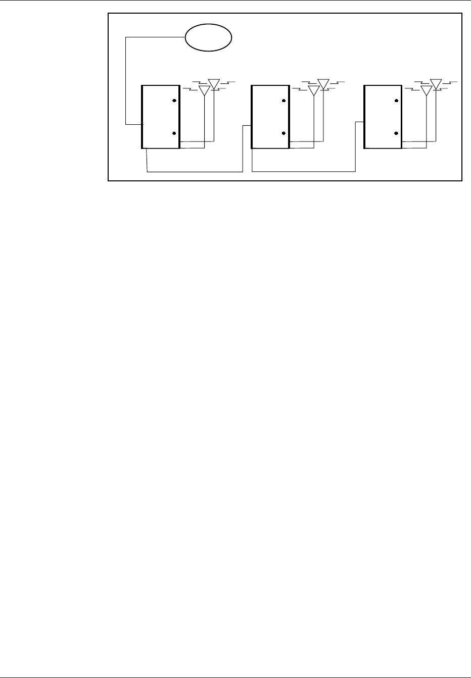
3.2.3.3 Cascade Configurations — RBS 884 Micro (1900 MHz)
RBS 884 Micro (1900 MHz) systems can be connected in a cascading
arrangement (see Figure 3-16 on page 3-26) with a single T1/E1 line in
order to reduce transmission costs. Cascading is used to expand a site and
to create different Radio Cabinet Groups (RCGs) at the same site.
Drop and insert considerations become important when planning the
cascading of an RBS site.
Each 1900 MHz micro base will become a separate Extension Module
Group (EMG) and have its own control channel (DS0 - 64 kbit/s channel)
on the PCM (T1/E1) transmission cable interconnections.
Additional Control Signaling Link (CLC) extraction time slots will be
required for each additional REMUX introduced to support cascading.
This allocation is determined by the operator or network provider. Each
REMUX will require all switch settings to be checked and reset as
necessary (see the Processes and Procedures part of this manual).
To maintain transmission quality, it is recommended that no more than
four RBS 884 Micro (1900 MHz) base stations be cascaded.
4/1551-EN/LZB 119 3312 Uae Rev PA4 1998-10-05 3-25
System Description
MSC
PCM (T1/E1)
PCM (T1/E1)
PCM (T1/E1)
MB1 MB2 MB3
MB = Micro Base
Figure 3-16. RBS 884 Micro (1900 MHz) Cascade Configuration
3-26 4/1551-EN/LZB 119 3312 Uae Rev PA4 1998-10-05

Part 4
Installation
1 Introduction . ................. 4-3
2 Safety Considerations . ............ 4-3
2.1 Cabinet Grounding ............ 4-3
2.2 Voltage Hazards . ............ 4-3
2.3 Radio Frequency Radiation ........ 4-4
2.4 Beryllium Oxide . ............ 4-4
2.5 Heavy Loads . . . ............ 4-5
3 Electrostatic Discharge (ESD) . . ........ 4-5
3.1 Storage and Transport . . ........ 4-6
3.2 ESD Wrist Strap . ............ 4-6
4 Tools . ..................... 4-6
5 Site Selection . ................. 4-7
5.1 Right-of-Way . . . ............ 4-7
5.2 Public Safety . . . ............ 4-7
5.3 Vulnerability . . . ............ 4-8
5.4 Accessibility . . . ............ 4-8
6 Transportation and Storage . . . ........ 4-8
7 Unpacking . . ................. 4-9
7.1 Required Tools . . ............ 4-9
7.2 Unpacking Procedure . . . ........ 4-10
8 Cabinet Installation . . . ............ 4-12
8.1 Required Materials and Tools . . . .... 4-12
8.2 Installation on a Pad . . . ........ 4-12
8.3 Installation on a Pole . . . ........ 4-15
8.4 Installation on a Wall . . . ........ 4-18
8.5 Installation on a Roof . . . ........ 4-21
9 Cable and Power Connections . ........ 4-22
9.1 Grounding ................ 4-22
9.2 Installing Batteries ............ 4-23
9.3 Installing AC Power ............ 4-26
9.4 Cable Installation . ............ 4-28
10 Setting the Unit Switches ............ 4-34
10.1 Prerequisites and Tools . . ........ 4-35
10.2 REMUX Switch Settings . ........ 4-36
10.3 EMRPM Switch Settings . ........ 4-44
11 External Cable Installation . . . ........ 4-45
11.1 Required Materials and Tools . . . .... 4-46
11.2 Antenna Connections . . . ........ 4-47
1/1551-EN/LZB 119 3312 Uae Rev PA4 1998-10-05 4-1

Installation
11.3 ANP/RFTL Connections .......... 4-47
12 Site Inventory .................. 4-53
12.1 Prerequisites . .............. 4-53
12.2 Site Inventory Procedure ......... 4-53
13 Equipment Power Up .............. 4-54
13.1 Prerequisites and Test Equipment ..... 4-55
13.2 Power-Up Procedure . .......... 4-55
14 Cold Start-up .................. 4-57
15 Completing the Installation . .......... 4-58
15.1 Prerequisites and Tools .......... 4-58
15.2 Installation Completion Procedure ..... 4-58
16 LED Indications . . . .............. 4-59
16.1 PSU LEDs . . .............. 4-60
16.2 TRX LEDs . . .............. 4-60
16.3 REMUX LEDs .............. 4-61
16.4 ANP (RFTL) LEDs . . .......... 4-61
16.5 STRM LEDs . .............. 4-62
16.6 ALM LEDs . . .............. 4-62
16.7 EMRPM LEDs .............. 4-63
16.8 ECU LEDs . . .............. 4-63
17 Site Expansion . . . .............. 4-64
17.1 Adding TRX Boards . .......... 4-65
17.2 Adding Cabinets . . . .......... 4-69
17.3 One-Sector Sites . . . .......... 4-72
17.4 Two-Sector Sites . . . .......... 4-74
17.5 Three Sector Sites . . .......... 4-77
18 RBS 884 Micro (1900 MHz) Cabinet Repainting . 4-83
18.1 Required Materials and Tools . . ..... 4-83
18.2 Cabinet Surface Preparation . . ..... 4-83
18.3 Cabinet Painting . . . .......... 4-84
4-2 1/1551-EN/LZB 119 3312 Uae Rev PA4 1998-10-05

Installation
1 Introduction
This part of the manual contains procedures for unpacking and installing
the RBS 884 Micro (1900 MHz) equipment. Additional procedures are
provided for switch configuration, cable installation, power up, and site
expansion.
The RBS 884 Micro (1900 MHz) cabinet can be installed on a wall, a
pole, or pedestal. The cabinet can also be repainted (refer to Section 18.3
on page 4-84).
2 Safety Considerations
2.1 Cabinet Grounding
This product is Safety class 1 equipment.
The RBS 884 Micro (1900 MHz) cabinet wiring is based on a single-point
ground system. The cabinet has an external earth-ground stud connection
on the bottom surface of the cabinet shell.
DANGER!
Any interruption of the protective (grounding) conductor or disconnection
of the protective ground terminal will cause a potential shock hazard that
could result in personal injury.
2.2 Voltage Hazards
DANGER!
Voltage over 100V is used in the AC equipment at the site. Observe safety
precautions. Contact with power can cause death. Do not be misled by the
term “low voltage.” Potentials as low as 50V can result in death.
Do not touch high voltage connections when working on energized
equipment.
1/1551-EN/LZB 119 3312 Uae Rev PA4 1998-10-05 4-3

Installation
DANGER!
Do not energize equipment before the Power Up procedure in this manual
is performed.
Perform the procedures in the order presented.
DANGER!
Never connect the power cable to the power unit when the unit is removed
from the cabinet.
2.3 Radio Frequency Radiation
DANGER!
Radio frequency radiation from an antenna may be a danger to health,
causing severe burns to skin and clothing.
Tell the MSC turn off the transmitters prior to working with or near
antennas.
2.4 Beryllium Oxide
Some equipment contains beryllium oxide in ceramic form.
Warning!
Beryllium oxide is poisonous and constitutes a health hazard if present in
finely dispersed form, such as dust or smoke, which can be inhaled. Read
local hazardous chemical regulations before working with beryllium oxide.
Units with components containing beryllium oxide are marked with a
warning label. For detailed information on properties, health and
environmental hazards, refer to the regulations issued by the local
authorities.
4-4 1/1551-EN/LZB 119 3312 Uae Rev PA4 1998-10-05

Installation
The following rules must be obeyed by all persons handling beryllium
oxide:
•Ceramics containing beryllium oxide must not be scraped, filed,
ground, treated with acid or machined in any other way.
•Compressed air must not be used to clean units containing beryllium
oxide.
•You must always wear protective gloves when handling beryllium
oxide.
•Use wet rags to collect dust and particles from damaged beryllium
oxide components. After use, place the rags in plastic bags and seal
the bags completely.
Scrapped beryllium oxide must be treated as environmentally hazardous
waste. Local authorities enforce regulations, regarding the treatment and
disposal of environmentally hazardous waste. Investigate the local
regulations which are applicable to you and comply with them.
2.5 Heavy Loads
Warning!
A heavy load lifted incorrectly can cause injury to persons and damage to
the equipment can result.
A heavy load is considered to be 10 kg (approximately 22 lbs).
Note: The RBS 884 Micro (1900 MHz), fully equipped, weighs 105
kg (230 lbs). Ericsson recommends two persons be present
during the maintenance.
3 Electrostatic Discharge (ESD)
The human body acquires static charge in all situations involving
movement. The body rubs against clothes and against a chair when sitting
down, and shoes rub against the floor. The same effect is achieved when
handling ordinary plastic materials.
If the body comes into contact with a grounded integrated circuit (IC)
component, this static charge may cause an electrostatic discharge (ESD)
to take place resulting in damage to the component.
To avoid component damage from ESD, always follow the instructions
for handling sensitive electronic components and circuit boards.
1/1551-EN/LZB 119 3312 Uae Rev PA4 1998-10-05 4-5
Installation
Always use ESD protection equipment when working with such
components and boards.
3.1 Storage and Transport
Store and transport components and circuit boards in their original
packaging.
Alternatively, use a conductive material or special IC carrier that either
short-circuits all contacts and pins, or insulates them from external contact.
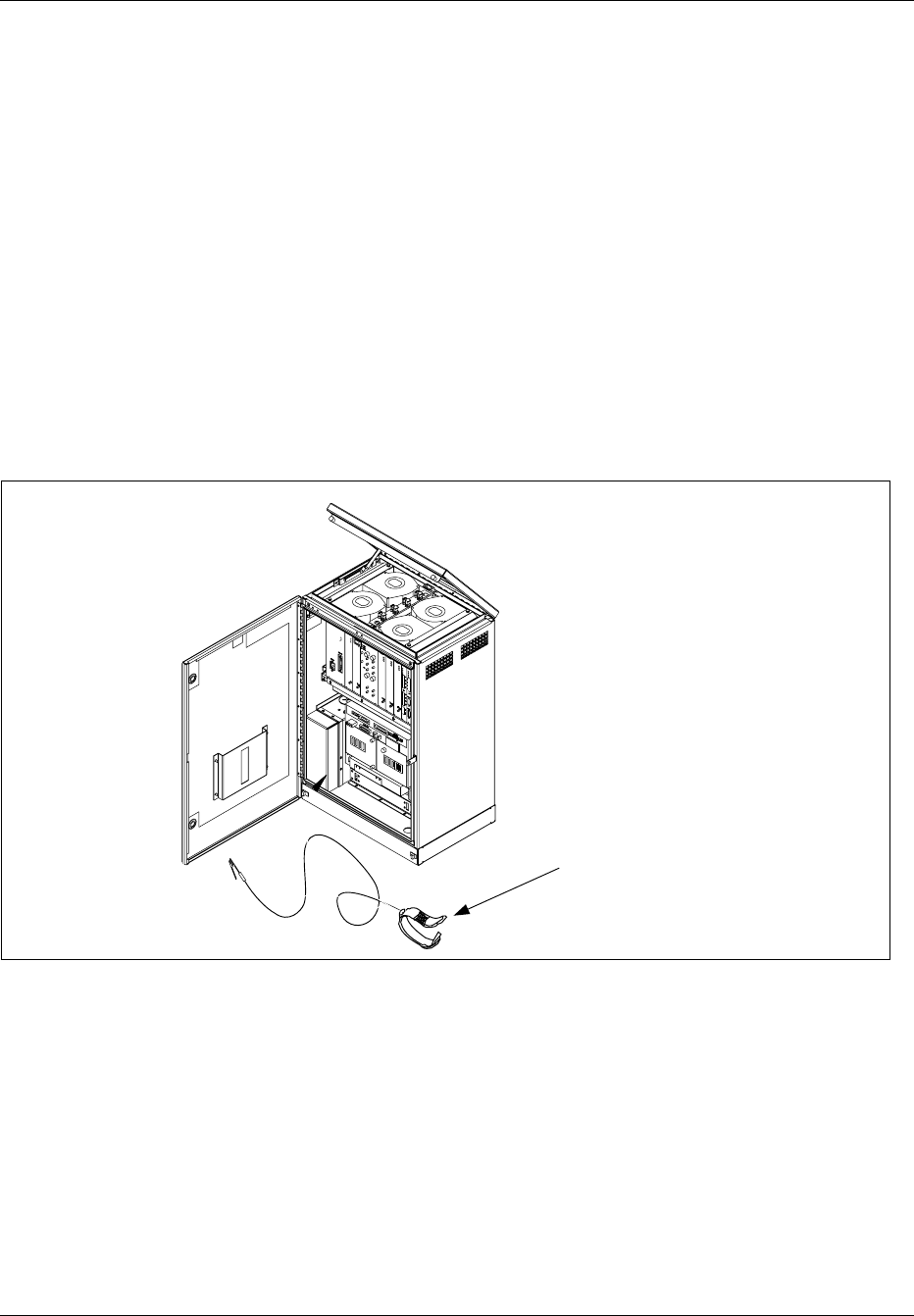
3.2 ESD Wrist Strap
When working with circuit boards and cables, an ESD Wrist Strap must be
used to avoid ESD damage. When the strap cable is supplied with a
“alligator” connector, it can be connected to an unpainted metal part of the
cabinet chassis as shown in Figure 4-1 on page 4-6.
ESD Wrist Strap
Note: Attach alligator clip to suitable
ground (unpainted surface) in cabinet.
Figure 4-1. ESD Wrist Strap connected to the RBS 884 Micro (1900 MHz) Cabinet
4 Tools
All the tools needed to unpack and install the cabinets, to connect the
grounding cables and braids, to set the switches, to install the cables, and
to perform power up, are shown in Table 5-1 on page 5-7.
4-6 1/1551-EN/LZB 119 3312 Uae Rev PA4 1998-10-05

Installation
Table 4-1. Tools List
Product Number Description
Metric Tape Measure1
Horizontal/Vertical Level1
(for wall mounting)
Pen
Drill1
Drill Bit1(10 mm for wall mounting)
LYB 250 01/14 ESD Wrist Strap and Cable2(with banana connector)
LTT 601 82 Torque Wrench set including:
- Torque Wrench set to torque 0.6 Nm
(to use with the SMA tool or the Torx bit TX10
- Torx bit TX10 (for cabinet unit screws)
- SMA tool (for the coaxial cables)
LTD 117 02 and
LTD 117 14
Unit Extractor Tool (Handle + Button)
AC Voltmeter1
(for checking the line voltage)
Tools for connecting the AC Power Cable to a Line
Power Access Point (if this is the local procedure)
1Included in Tool Kit LTT 601 044/1
2Included in Tool Case LTT 601 84
5 Site Selection
5.1 Right-of-Way
The installing company should acquire the rights of way from landowners
and obtain permits or other approvals from public authorities before
starting construction.
The RBS 884 Micro (1900 MHz) cabinet should be placed in servitudes,
on dedicated (recorded) easements, or on property owned by the company.
Avoid unrecorded easements.
If the location is on a rooftop, the same rights-of-way as stated above
apply. Additional considerations and approvals may be required, such as
rooftop loading
5.2 Public Safety
Public safety and street rights-of-way should be used only when there is
adequate space to place the cabinet and provide safe working conditions.
1/1551-EN/LZB 119 3312 Uae Rev PA4 1998-10-05 4-7

Installation
The cabinet should be placed so that it will not obstruct automobile or
pedestrian traffic.
5.3 Vulnerability
Installation locations should be protected against accidents or vandalism.
Use protected posts when installing cabinets near automobile traffic and
parking areas.
Do not place the cabinets below grade or in flood prone areas. The cabinet
should always be located on a site above the 100–year flood plain. The site
should not be subject to water run off or flash flooding during heavy rains.
If an area is subject to frost, the site must be free of heaving.
For pole-mounted cabinets, ensure the pole can support the cabinet weight
(approximately 105 kg (230 lbs).
5.4 Accessibility
For safety, the cabinet should be easily accessible with adequate parking.
Do not install the cabinet within 42.0 inches (1066.8 mm) of any
obstruction, such as a fence, hedge, or tree.
6 Transportation and Storage
Caution!
Follow all appropriate local transportation, handling, and safety practices
when transporting and storing the cabinet to a staging or installation site.
The cabinet is shipped in a wooden box on a wooden pallet.
Warning!
To avoid possible damage to the cabinet, do not remove the packaging or
pallet from the cabinet until it is at the installation or staging site.
If the cabinet packaging appears damaged, do not accept the unit or
component from the shipper. Damaged packaging could indicate cabinet or
equipment damage.
4-8 1/1551-EN/LZB 119 3312 Uae Rev PA4 1998-10-05
Installation
Always use proper lifting equipment, such as forklift, to raise the cabinet
and pallet.
Always store the cabinet and battery components in the upright position to
avoid possible damage.
Caution!
Do not stack units for transportation or during storage.
7 Unpacking
The RBS 884 Micro (1900 MHz) cabinet is shipped in a wooden box on a
wood pallet.
7.1 Required Tools
The tools required to unpack the cabinet are shown in Table 4-2 on page
4-9.
Table 4-2. Tools Required to Unpack cabinet
Product Number Description
N/A Tamper resistant wrench (supplied with cabinet)
N/A Socket or adjustable wrench (for pallet bolts)
N/A Hammer
N/A Large flat-blade screwdriver
N/A Small flat pry bar or crow bar
1/1551-EN/LZB 119 3312 Uae Rev PA4 1998-10-05 4-9

Installation
7.2 Unpacking Procedure
7.2.1 Receiving Materials
Warning!
To avoid damaging the cabinet, do not remove the pallet or wooden box
from the cabinet until the cabinet is transported to a staging or installation
site.
1. After receiving all materials, check packing slip to ensure that all
boxes/crates are accounted for.
2. Inspect all boxes and crates for any visible damage.
3. Report any material shortages or damages to your local logistics
coordinator.
7.2.2 Unpacking
1. Remove all packaging material from around the cabinet and the
pallet.
Note: Do not remove the pallet until the cabinet is ready to be
lifted into the mounting position.
2. Use a tamper-resistant wrench to open the doors. Insert the wrench
into a security bolt and turn it 1/4–turn counterclockwise. Repeat
for the other bolt. Open the door.
Note: The 1/4-turn tamper resistant wrench is in a plastic bag
taped to the outside of the Main Cabinet.
3. As the door is opened, secure the wind latch at the top of the door.
Open the door until the shoulder slides into the slot at the end of
the bar. To release the wind latch, lift up on the bar.
4. Inspect moving parts, mounting hardware, connectors, and
electronic equipment. If the cabinet or any equipment appears to be
damaged, follow the local procedures or contact the logistics
coordinator.
5. Check the packing slip and ensure all parts ordered are received.
6. Remove all packaging and dispose of it according to local practices.
4-10 1/1551-EN/LZB 119 3312 Uae Rev PA4 1998-10-05

Installation
7.2.3 Lifting the Cabinet
DANGER!
To avoid injury or equipment damage, follow all local safety practices
while lifting the cabinet. Wear all locally recommended safety equipment.
Manual cabinet lifting is not recommended. To avoid injury, use proper
lifting equipment. Attach any lifting equipment to lifting ears located on
rear of cabinet. Ensure there are no obstructions around cabinet.
Warning!
The RBS 884 Micro (1900 MHz) cabinet will tilt forward when raised by
the lifting ears located on the rear of the cabinet.
Observe the following procedures when lifting the RBS 884 Micro (1900
MHz) cabinet from the pallet:
•Keep bystanders away from work operations at all times.
•Do not lift the cabinet over people. Do not let anyone work, stand,
or pass under a cabinet being lifted.
•All persons working with lifting equipment must wear standard
safety headgear and (when required) gloves.
•When lifting the cabinet and pallet with a forklift use care to not
damage cabinet with forks. Lift from the open ends of the pallet.
•For installations where the cabinet will be mounted at higher
locations on a wall or pole, a crane or similar lifting equipment is
recommended. Do not attempt to manually lift cabinet. Follow all
local safety practices.
7.2.4 Removing Cabinet from Pallet
Perform the following steps to remove the cabinet from the pallet:
1. Locate the four pallet mounting bolts. There four bolts (one in
each corner) in the bottom of the cabinet. Using a socket wrench
or adjustable wrench, remove the four pallet mounting bolts.
2. Secure the cabinet door before moving the cabinet.
1/1551-EN/LZB 119 3312 Uae Rev PA4 1998-10-05 4-11

Installation
8 Cabinet Installation
This section describes the procedure for installing the RBS 884 Micro
(1900 MHz) cabinet on a pad, pole, wall, or roof. Manual cabinet lifting is
not recommended. The RBS 884 Micro (1900 MHz) cabinet requires
mechanical lift assistance for wall or pole mounting. Attach any lift
devices to lifting ears on rear of cabinet. If required, a temporary support
structure can be installed prior to installing the cabinet. Position the
cabinet on the support structure during installation. Do not stand under
cabinet at any time.
8.1 Required Materials and Tools
8.1.1 Materials
Refer to the CMS 8800 Site Materials Catalog for general materials to
install the RBS 884 Micro (1900 MHz) antennas and cables. Cabinet
mounting materials are specified in the individual installation procedures.
8.1.2 Tools
The tools required to mount RBS 884 Micro (1900 MHz) cabinets are
shown in Table 4-3 on page 4-12.
Table 4-3. Tools for Cabinet Installation
Product Number Description
N/A Mechanical lifting equipment capable of supporting
cabinet weight (refer to local safety procedures)
N/A Metric Tape Measure
N/A Horizontal/Vertical Spirit Level
N/A Pen
N/A Drill
N/A 10 mm Drill Bit
N/A M13 Socket Wrench
LSA 126 21/30 Torx Angle Screwdriver TX30
8.2 Installation on a Pad
The pedestal base mounting kit is used for pad mounting RBS 884 Micro
(1900 MHz) cabinets. The pedestal base mounts on a concrete pad and is
used as the base for the cabinet. A removable front panel allows easy
access for installation of the pedestal, cabinet, and any cables.
Knock-outs are provided at both ends for routing the cables through the
side walls of the pedestal base to the underside of the cabinet floor. The
4-12 1/1551-EN/LZB 119 3312 Uae Rev PA4 1998-10-05
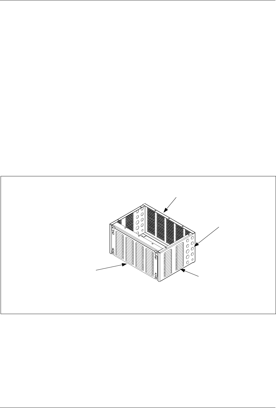
Installation
knock-outs are not used if the cables enter the pedestal through conduits
from beneath the pad.
Patterned vents allow sufficient air flow to enter the cabinet for the cabinet
cooling/heating requirements.
1. Clean all litter from the foundation pad surface.
2. Dress the cable or conduit to not interfere with the pedestal base
installation.
3. Remove any bolts and washers installed in the concrete anchors. Set
the hardware aside to attach the pedestal base to the pad.
4. Locate the Pedestal Mounting Kit.
5. Place the pedestal base on the concrete pad. Figure 4-2 on page 4-13
illustrates the pedestal base. Align the pedestal base with the screw
anchors that were installed when the concrete pad was poured. If the
screw anchors were not installed at that time, use the pedestal base to
mark the mounting holes for the anchors and drill. See Figure 4-3 on
page 4-14 for the location of the mounting holes on the pedestal base.
Depth
432 MM
(17.0 IN)
Height
305 MM
(12.0 IN)
Removable front panel
for access to cables
and mounting points
under cabinet Width
610 MM
(24.0 IN)
Vents for air entry
into cabinet
Knock-outs for
cable entry/exit
Pedestal Base for Pad Mounting
the RBS 884 Micro (1900 MHz)
cabinet
Figure 4-2. Pedestal Base
1/1551-EN/LZB 119 3312 Uae Rev PA4 1998-10-05 4-13
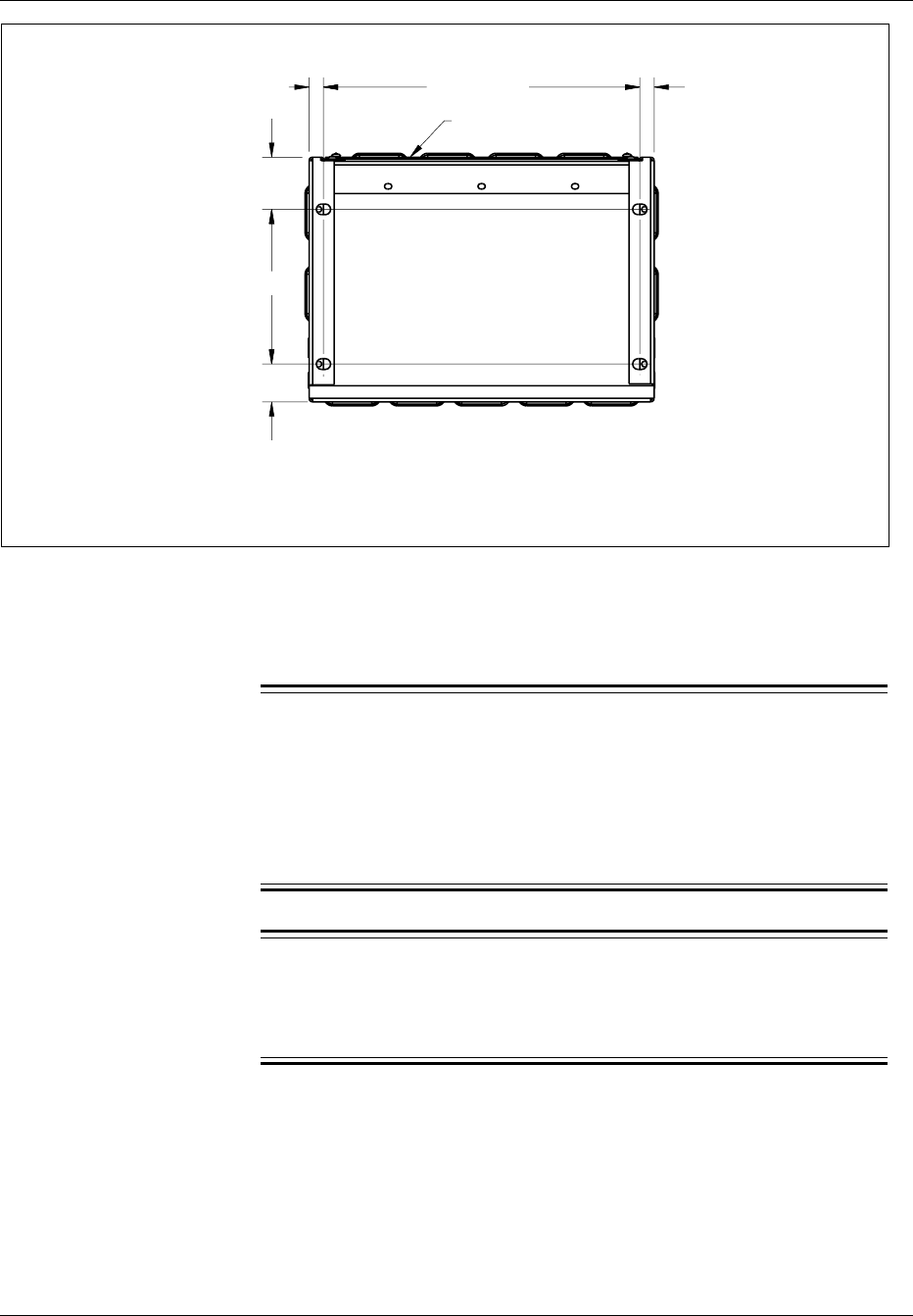
Installation
Bottom view of pedestal base
showing mounting pattern
for securing to concrete pad
Front of Pedestal
10.75"
(273.05 mm)
2.63"
(66.80 mm)
3.62"
(91.95 mm)
1.00"
(25.4 mm)
22.00
(558.80 mm) 1.00
(25.4 mm)
Figure 4-3. Bottom View of Pedestal Mount
6. Attach the pedestal base to the concrete pad and secure with the
appropriate size bolts.
7.
DANGER!
To avoid injury or equipment damage, follow all local safety
practices while lifting the cabinet. Wear all locally approved safety
gear. Manual cabinet lifting is not recommended. Use proper lifting
equipment. Attach any lifting devices to lifting ears on rear of
cabinet. Keep bystanders away from work operations at all times.
Warning!
The RBS 884 Micro (1900 MHz) cabinet will tilt forward when
raised by the lifting ears located on the rear of the cabinet.
Place the cabinet onto the pedestal pad mount. Ensure the cabinet is
aligned with the pedestal.
8. Use the tamper-resistant wrench and remove the front panel on the
pedestal base. Secure the cabinet to the pedestal base.
9. If not using cabinet mounted antennas, remove lifting ears from the
cabinet (optional).
4-14 1/1551-EN/LZB 119 3312 Uae Rev PA4 1998-10-05

Installation
10. Install any cabinet mounted antennas.
8.3 Installation on a Pole
Warning!
For installations where the RBS 884 Micro (1900 MHz) cabinet will be
pole mounted, a crane or similar lifting equipment is recommended.
Ensure the cabinet is supported by the lifting equipment at all times during
the installation. The cabinet will tilt forward when raised by the lifting
ears located on the rear of the cabinet. Keep bystanders away from the
work area at all times.
1. Locate the Pole Mounting Kit.
2. A detachable mounting bracket secures the cabinet to the pole. See
Figure 4-4 on page 4-16.
1/1551-EN/LZB 119 3312 Uae Rev PA4 1998-10-05 4-15
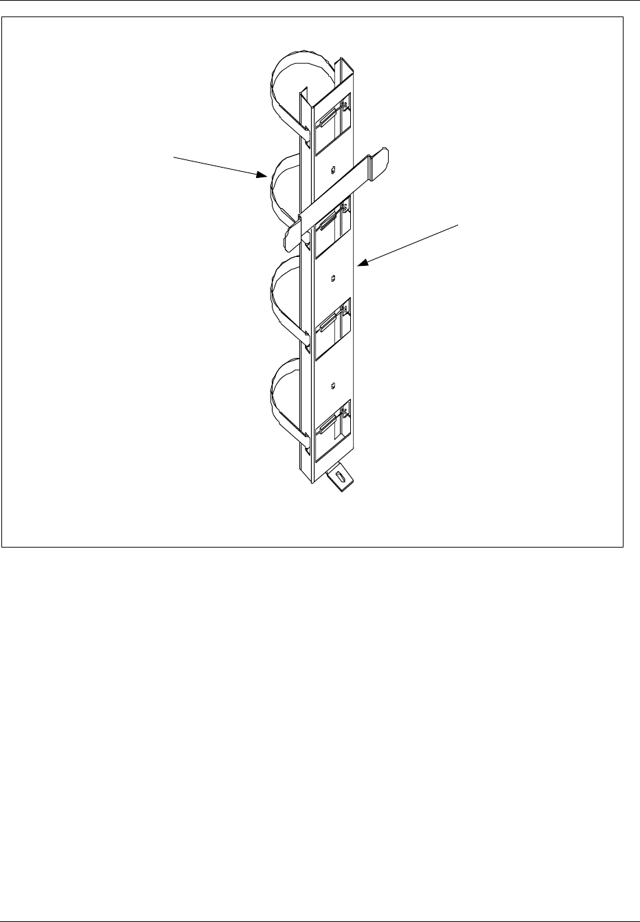
Installation
Mounting Strap
Pole/Wall Mount Bracket
Figure 4-4. Pole-Mount Components
3. Check the components in the Pole Mounting Kit and verify the kit is
complete.
4.
Note: If the pole-mount bracket is to be bolted to pole,
mark and drill holes in the pole prior to lifting bracket into location.
If two or more cabinets are to be installed, a minimum of 12 inches
(305 mm) clearance must be maintained between cabinets.Install the
pole-mount bracket on the pole at the desired height (see site survey
documentation). Ensure the bracket is level and tighten the hardware.
See Figure 4-5 on page 4-17.
4-16 1/1551-EN/LZB 119 3312 Uae Rev PA4 1998-10-05
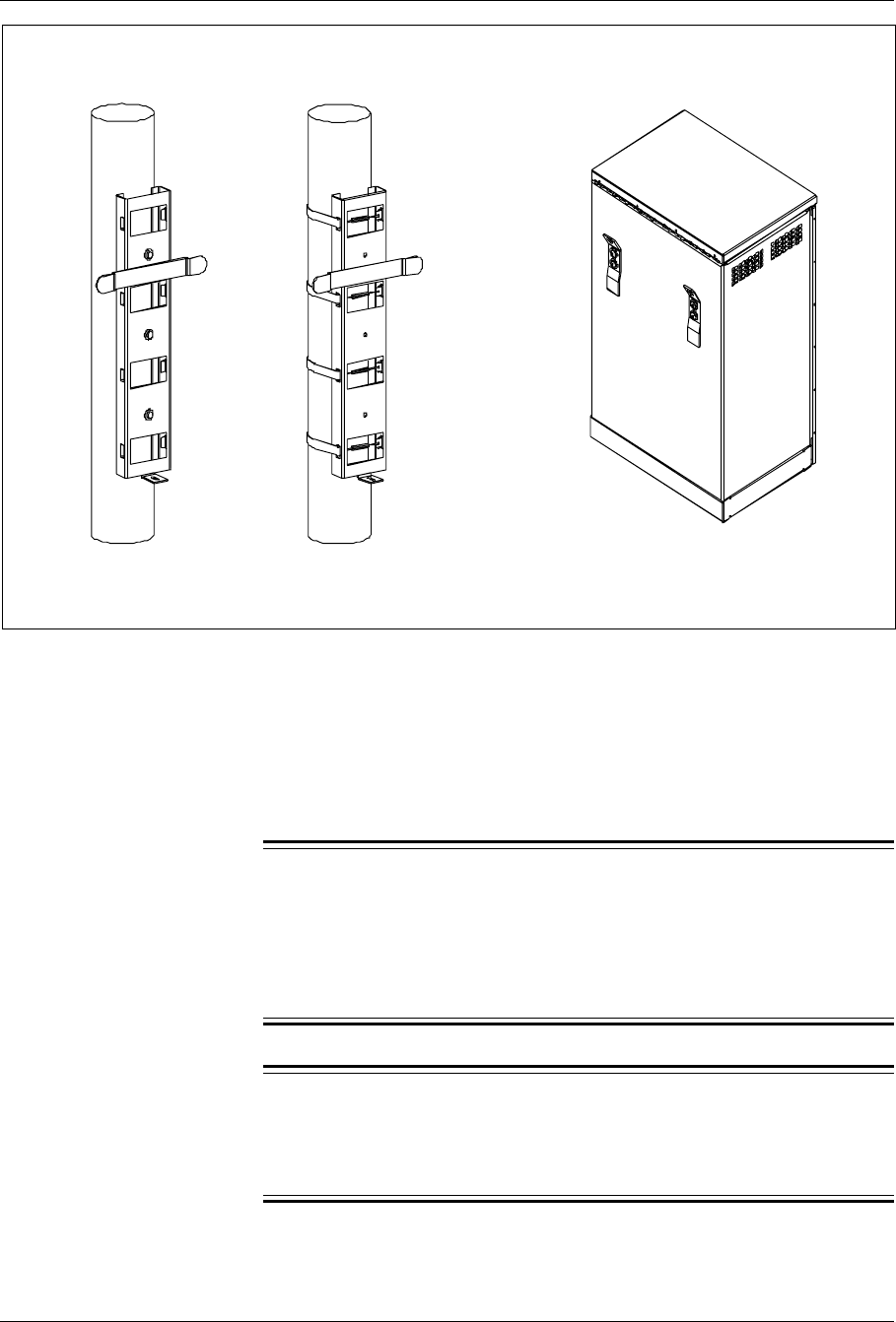
Installation
Figure 4-5. Rear View of Bracket Installed on Pole
5. Locate the four mounting bolts (one in each corner) in the base of
the cabinet. Remove the four pallet mounting bolts. Remove the
pallet and dispose in accordance with local practices.
6. Secure the cabinet door before lifting the cabinet.
7.
Warning!
Ensure the cabinet is supported by the lifting equipment at all times
during the installation. The RBS 884 Micro (1900 MHz) cabinet will
tilt forward when raised by the lifting ears located on the rear of the
cabinet.
Caution!
Do not lift the cabinet over people. Do not let anyone work, stand,
or pass under a cabinet while it is being lifted.
1/1551-EN/LZB 119 3312 Uae Rev PA4 1998-10-05 4-17
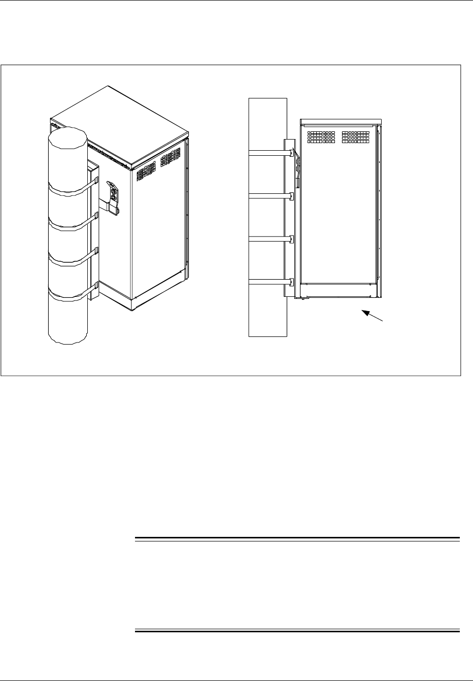
Installation
Attach the lifting cables or sling to the lifting ears on the mounting
bracket. Carefully lift the cabinet and set the cabinet on the
mounting bracket attached to the pole. See Figure 4-6 on page 4-18.
L-Bracket
Figure 4-6. Cabinet Mounted on T-Bracket
8. If required, adjust cabinet horizontally to align with L-bracket.
9. Install the L-bracket to the bottom of the cabinet.
10. Install any cabinet mounted antennas.
8.4 Installation on a Wall
Warning!
Ensure the cabinet is supported by the lifting equipment at all times
during the installation. The RBS 884 Micro (1900 MHz) cabinet will
tilt forward when raised by the lifting ears located on the rear of the
cabinet.
4-18 1/1551-EN/LZB 119 3312 Uae Rev PA4 1998-10-05
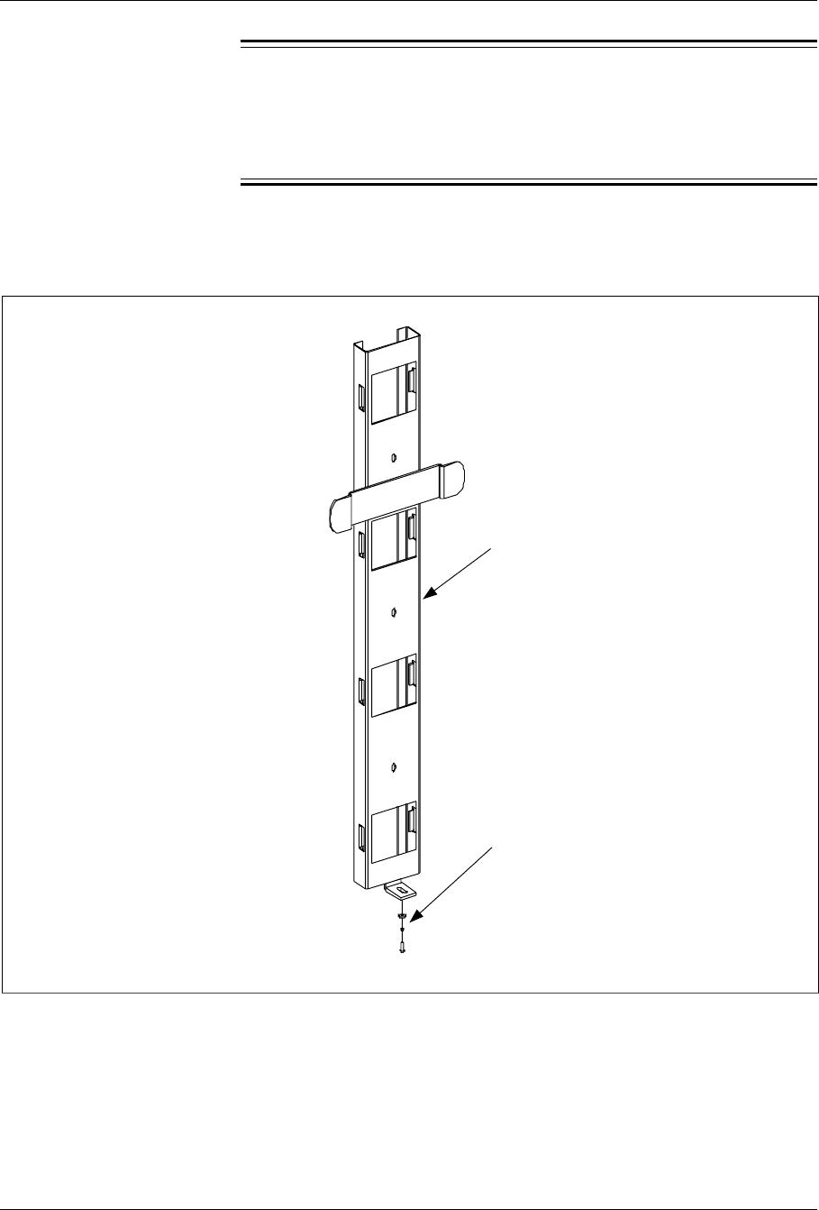
Installation
Caution!
A fully configured cabinet weighs over 105 kg (230 lbs). Ensure the
wall can support the cabinet. Reinforce the wall structure if
necessary.
1. Ensure the cabinet is upright
2. Locate the Wall Mounting Kit. See Figure 4-7 on page 4-19.
Mounting Bracket
Hardware
Figure 4-7. Wall-Mount Components
3. Check the components in the wall mounting kit and verify the kit is
complete.
4. Locate the place on the wall where the bracket will be mounted and
drill holes appropriate for the length of the anchor to be used. Table
4-4 on page 4-20 is a list of the suggested anchoring hardware.
1/1551-EN/LZB 119 3312 Uae Rev PA4 1998-10-05 4-19
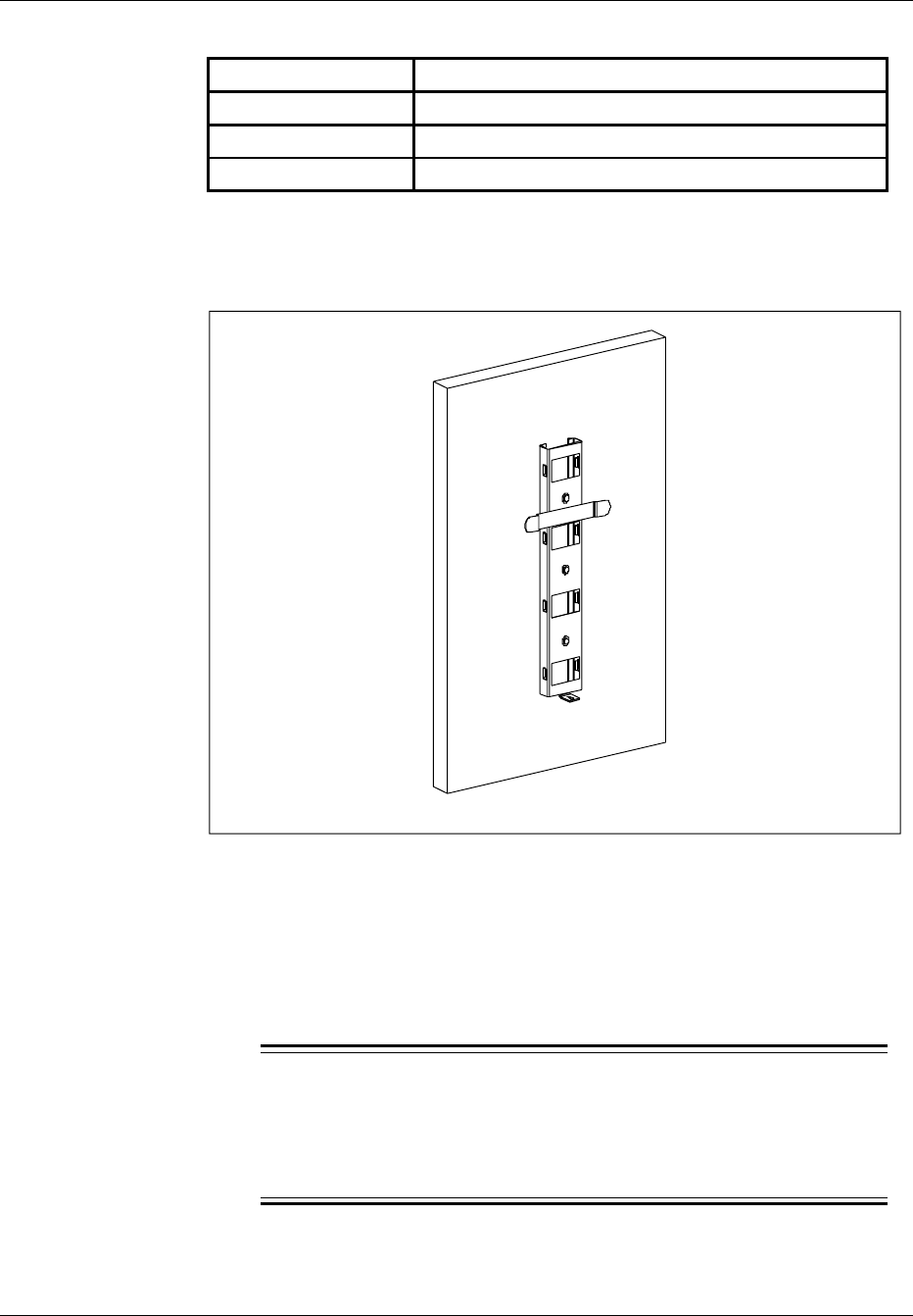
Installation
Table 4-4. Wall Anchors
Type of Wall Recommended Anchor
Masonry 4-1/4-in. x 1-1/4-in. hammer drive anchors
Wood 4-1/2-in. No. 14 RH galvanized wood screws
Hollow Hollow wall mounting not recommended
5. Secure the bracket to the wall using an appropriate anchor. See
Figure 4-8 on page 4-20. Level the bracket before tightening the
bolts.
Figure 4-8. Installing Cross Arm to Wall
6. Locate the four mounting bolts (one in each corner) in the base of
the cabinet. Remove the four pallet mounting bolts. Remove the
pallet and dispose of it in accordance with local practices.
7. Secure the cabinet door before lifting the cabinet.
8.
Caution!
A fully configured cabinet weighs 105 kg (230 lbs). Mechanical
lifting equipment is required to lift cabinet into position. Manual
lifting is not recommended.
Lift the cabinet and place it on the cross arm bracket.
4-20 1/1551-EN/LZB 119 3312 Uae Rev PA4 1998-10-05
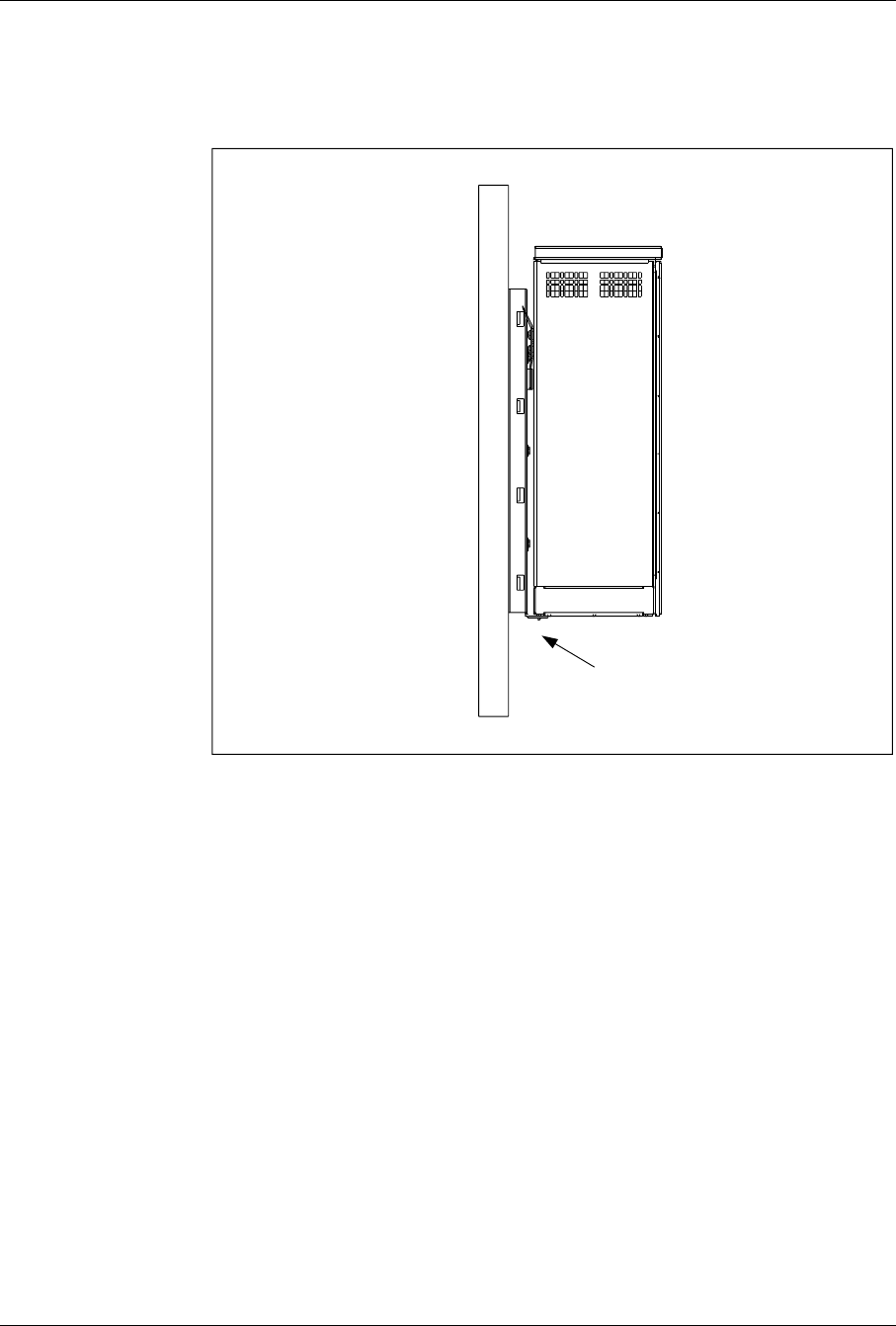
Installation
9. If required, adjust cabinet horizontally to align with L-bracket.
10. Install the L-bracket to the bottom of the cabinet. See Figure 4-9 on
page 4-21.
L-Bracket
Figure 4-9. Wall Mounted cabinet
11. Install any cabinet mounted antennas.
8.5 Installation on a Roof
1. Locate the four base mounting bolts (one in each corner) in the
bottom of the cabinets.
2. Remove the four pallet mounting bolts. Remove the pallet and
dispose of in accordance with local practices.
3. Secure the cabinet door before lifting the cabinet.
4. Roof mounted cabinet installations vary depending on the site
configuration and type of roof. Refer to the site specific engineering
specifications for further information on a roof mounted cabinet.
1/1551-EN/LZB 119 3312 Uae Rev PA4 1998-10-05 4-21

Installation
9 Cable and Power Connections
9.1 Grounding
Warning!
Follow all local safety practices, observe all general safety precautions,
and wear all approved safety equipment when performing any grounding
procedures. Perform all required testing before and after cabinet
installation. Only qualified personnel or electricians should install the
ground connections.
Caution!
Ensure all local all building codes and National Electrical Code® (NEC)
are met when installing grounding.
Note: Ensure all ground connections are clean and free of oxidation
or rust. Clean all contact surfaces as required
9.1.1 Perimeter Ground (Pad-Mount only)
1. Install the earth ground or ground ring before installing the cabinet.
2. Ensure that the earth ground or ground ring is connected to the
principal ground.
3. Connect all antennas to a ground point according to the Site
Engineering Manual, specific engineering specifications, and
installation drawings.
4. Coax transmission cable (50 ohm) passes through the supplied
lightning surge suppressors on the earthing plate.
5. Use an ammeter and check to ensure there is no AC or DC current
on cables already terminated to the earth ground point. If current is
present, do not proceed with further grounding until the current no
longer exists.
Note: The field ground can accept a 10-gauge solid to a
2-gauge stranded copper ground wire.
9.1.2 Cabinet Ground Cabling
The RBS 884 Micro (1900 MHz) earth ground is connected to an external
grounding lug located on the bottom shell of the cabinet.
4-22 1/1551-EN/LZB 119 3312 Uae Rev PA4 1998-10-05

Installation
9.2 Installing Batteries
Warning!
Equipment temperatures can reach up to 60 C (140 F). Use extreme caution
when working around the battery enclosure or other internal components.
Caution!
To avoid injury or equipment damage, follow all locally approved safety
practices and wear appropriate safety equipment when working with
batteries. Turn off power to the 40A breaker so there is no power supplied
to the cabinet.
A +24Vdc battery system is standard with the cabinet for two minutes of
battery reserve. Two 12V batteries are installed in the battery tray in the
lower left area of the cabinet. The batteries are connected in series by a
copper strap.
Note: All batteries are configured with steel cases for applications
where temperatures can reach up to 60 C (140 F).
Use the following steps to install the batteries into the tray and connect the
batteries to the system:
Note: The float is calibrated for +27.0 to 27.6 Vdc at the batteries.
The float is set at the factory and sealed. This setting is not
adjusted by the user.
Note: Torque at the bolt is 50 in-lbs maximum.
1. Position the BAT circuit breaker on the left side of the AC/DC
Distribution Box to OFF. See Figure 4-10 on page 4-24.
2. Remove the four screws from the battery cover and remove the
cover from the battery compartment.
3. If installed, remove the battery hold-down bracket(s) from left wall
of battery compartment.
4. Remove the battery tray from the battery compartment. Ensure
battery heater remains in position in bottom of compartment.
5. Install the batteries into the battery tray as illustrated in Figure 4-11
on page 4-25. Attach the hold-down bracket to the battery tray.
6. Connect the center terminals (positive terminal of battery 1 to
negative terminal of battery 2) with the copper strap. Do not
tighten the negative terminal of battery 2 at this time. See Figure
4-11 on page 4-25
1/1551-EN/LZB 119 3312 Uae Rev PA4 1998-10-05 4-23
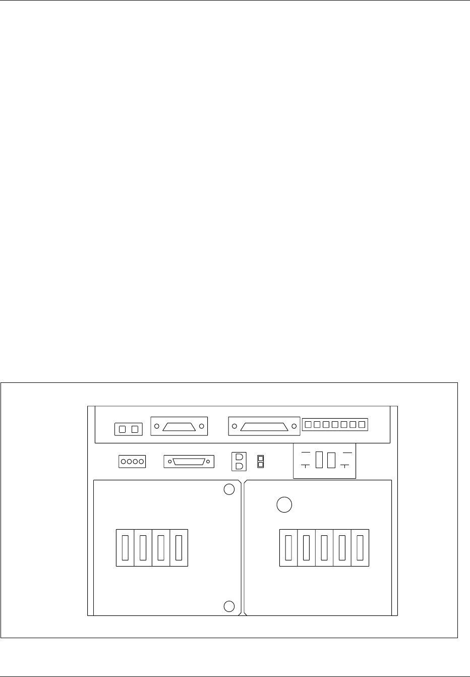
Installation
7. Connect the battery cable assembly to the batteries as follows:
– Connect the 8-gauge red cable to the positive terminal (+) of
battery 2. See Figure 4-11 on page 4-25.
Note: Ensure that the battery connections will not contact
wall of battery compartment or cover. Reposition
connectors as necessary to provide clearance.
– Connect the 8-gauge black cable to the negative terminal (-) of
battery 1.
– Connect one of the 18-gauge white wires labeled POST to the
negative terminal of battery 1. Connect the other 18–gauge
white wire to the negative terminal of battery 2.
8. Tighten all remaining battery connections.
9. Install the battery tray assembly in the battery compartment.
Ensure the battery cable assembly is not pinched against the battery
compartment. Ensure the battery heater is in proper location under
battery tray.
10. Place the hold-down bracket over the screw on the side wall of the
battery compartment. Secure with a hex nut.
11. Connect the power connector of the battery cable assembly to the
connector at the top of the battery compartment.
12. Connect the Failed Battery Sensor connector.
13. Install the battery cover on the battery compartment with the four
screws.
ALM CABLE ECU CABLE
SUBRK PWR
FAN PWR CSU
SENSORS
AC
CONNECTED
MAIN PSU MAIN
HTR BAT
HTR GFI
OUTLET
BAT ECU CSU FANS
BAT COMP
BAT
ALM DOOR
ALM
ON
OFF
Figure 4-10. AC/DC Distribution Box
4-24 1/1551-EN/LZB 119 3312 Uae Rev PA4 1998-10-05
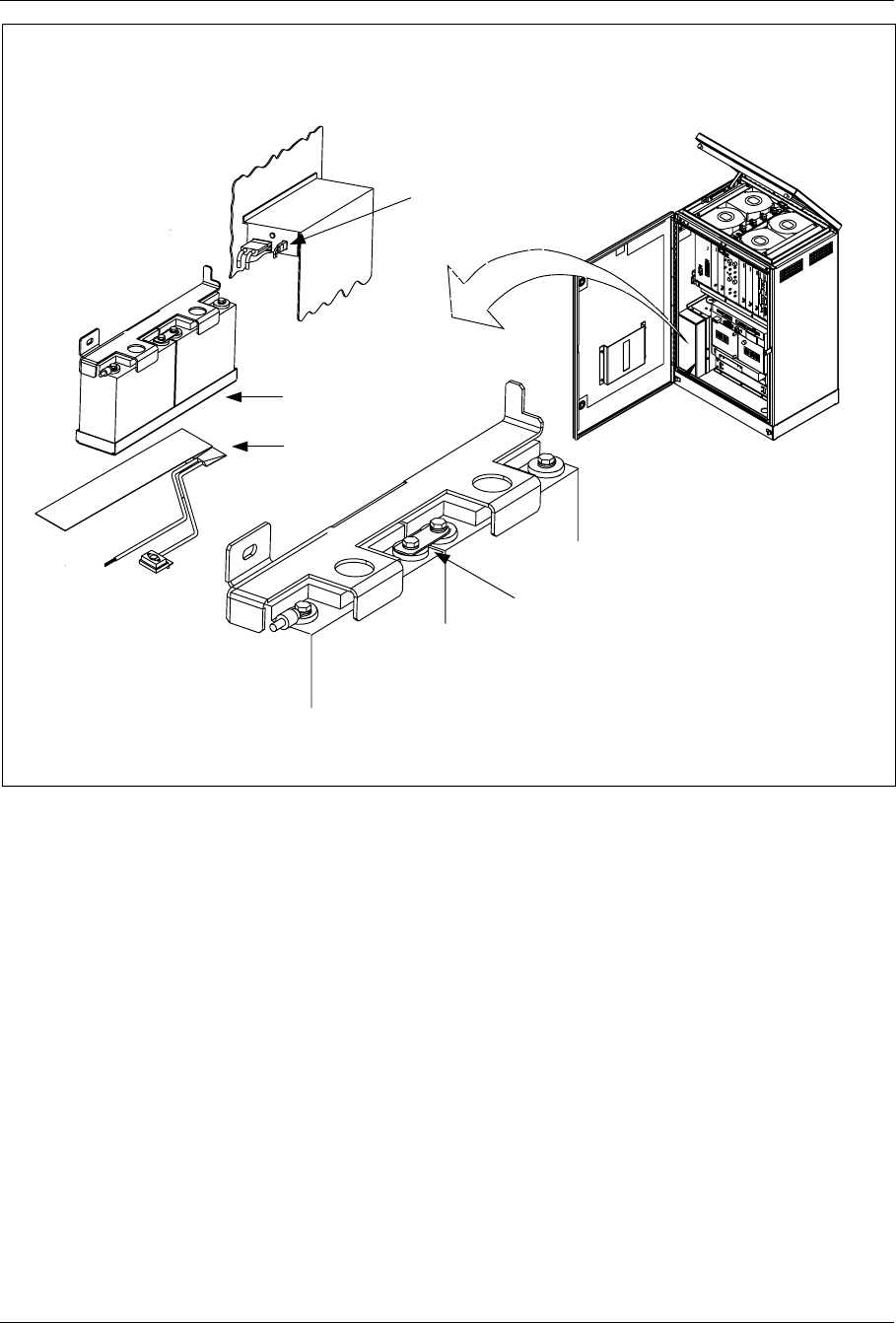
Installation
+
+
-
-
Copper Strap
Battery 1
Battery 2
Battery Tray
Battery Heater
Failed Battery
Sensor Connector
Figure 4-11. Battery Installation in Cabinet
1/1551-EN/LZB 119 3312 Uae Rev PA4 1998-10-05 4-25

Installation
9.3 Installing AC Power
DANGER!
AC power can result in death, injury, or equipment damage. Observe all
safety precautions as specified by local building codes and the National
Electrical Code® (NEC). All procedures should be performed by a
licensed electrician.
DANGER!
Before installation, bond the AC grounding electrode system to an AC
main service power neutral/ground bus. Contact the local power company
or the appropriate local personnel for information about codes or
restrictions for the installation.
Note: The cabinet requires 110V, 60 Hz or 230V, 50 Hz, two-wire
plus ground commercial power. All AC equipment from the
service drop to the pad is provided locally. Consult the NEC
and local codes for the correct wire size, as the wire size
depends on the distance to the source. Figure 4-12 on page
4-27 shows the location of the AC/DC Distribution Box in the
cabinet.
4-26 1/1551-EN/LZB 119 3312 Uae Rev PA4 1998-10-05

Installation
ALM CABLE ECU CABLE
SUBRK PWR
FAN PWR CSU
SENSORS
AC
CONNECTED
MAIN PSU MAIN
HTR BAT
HTR GFI
OUTLET
BAT ECU CSU FANS
BAT COMP
BAT
ALM DOOR
ALM
ON
OFF
Figure 4-12. AC/DC Distribution Box
1. Before installing the AC power, ensure that the AC ground system
is installed. The ground system must be in compliance with local
practices and building codes. Refer to the Site Engineering Manual
for more information.
2. Open the cabinet and open the AC/DC Distribution Box.
3. Install liquid-tight conduit through bottom of cabinet up to 90
conduit fitting located on right side of AC/DC Distribution Box.
4. Ensure the opening in the bottom of the cabinet is sealed with a
conduit fitting or other device to prevent air and water leakage into
cabinet.
5. Pull AC and ground wires through conduit into the AC/DC
Distribution Box.
6. Connect ground wire to ground bus inside AC/DC Distribution Box.
7. Connect neutral wire to neutral bus inside AC/DC Distribution Box.
8. Remove clear cover from rear of circuit breakers and install line
wire to the bus bar on the Main circuit breaker.
9. Replace clear cover on rear of circuit breakers and close AC/DC
Distribution Box.
1/1551-EN/LZB 119 3312 Uae Rev PA4 1998-10-05 4-27

Installation
9.4 Cable Installation
This section describes installing cables in the cabinet. Use the procedure
for one of the following types of installation:
•Pedestal (Pad) Mount, Section 9.4.1 on page 4-28
•Pole Mount, Section 9.4.2 on page 4-32
•Wall Mount, Section 9.4.3 on page 4-33
•Roof Mount, Section 9.4.4 on page 4-34
•Site Expansion, Section 17 on page 4-64
Caution!
Ensure all site grounding is installed and functioning before installing
cables. Observe all local safety precautions and wear all appropriate
locally approved safety equipment during installation procedures.
9.4.1 Pedestal Mount Cable Installation
Caution!
When installing coaxial cable or cable conduit, follow the minimum
bending radius requirements for the type of cable being installed.
1. Using a tamper resistant wrench, remove the front panel from the
pedestal base so cables or conduit can be routed to the cabinet. See
Figure 4-13 on page 4-30
2. Route the antenna and T1(E1) conduit into the base of the cabinet.
See Figure 4-13 on page 4-30.
3. Route AC power and ground conduit into base of cabinet.
4. Separate the cables into groups according to cable type. Secure the
cables with tie-wraps until they are ready to be installed.
5. Route the antenna jumper cables into the base of the cabinet and
connect them to the antenna connectors on the bottom of the
earthing plate. See Figure 4-14 on page 4-31.
6. Bond and ground the T1(E1) drop wires according to local
practices before installing them into the cabinet.
4-28 1/1551-EN/LZB 119 3312 Uae Rev PA4 1998-10-05

Installation
7. Route the T1(E1) cable through conduit into the base of the
cabinet. Connect cable to the T1(E1) Primary Surge Suppressor
located on the right-hand side of the cabinet. See Figure 4-15 on
page 4-32. Note that the connector block is grounded to the I/O
plate at the factory.
Note: The hex-nut activators on the T1(E1) Primary Surge
Suppressor block are colored white for tip wires and
orange for ring. The large ports under the activator
clock accommodate 18.5 to 20 AWG wire termination.
The small ports accommodate 22 to 24 AWG wire
termination.
Note: Wire stripping or staggering is not needed when using
the T1(E1) Primary Surge Suppressor block. The
Primary Surge Suppressor provides straight-through
access for wire terminations.
8. Terminate the wires on the connector block as follows:
a. Trim the ends of the wire. Split the drop leads approximately
two inches. Using a standard 216–type wrench, carefully back
off the activator screw until you feel a stop. The wrench will lift
up approximately 1/4–inch into the open position.
b. Insert the wire into the large or small port on the side of the
activator. Tighten the hex nut on the top of the activator until
the tensions stops. DO NOT OVERTIGHTEN.
c. If testing or if a talk pair is needed, insert test leads into the hex
nut on the appropriate activator.
d. To reinstall wires, trim the wire ends and split the drop wire
leads approximately two inches and terminate according to the
above procedure.
e. After wiring, keep all activators in the down position for good
housekeeping.
9. After all cables are installed, turn on the AC power.
10. Watch the LEDs on each board and that the unit is operating
properly. Consult the troubleshooting part of the Installation and
Maintenance manual for units that are malfunctioning.
1/1551-EN/LZB 119 3312 Uae Rev PA4 1998-10-05 4-29
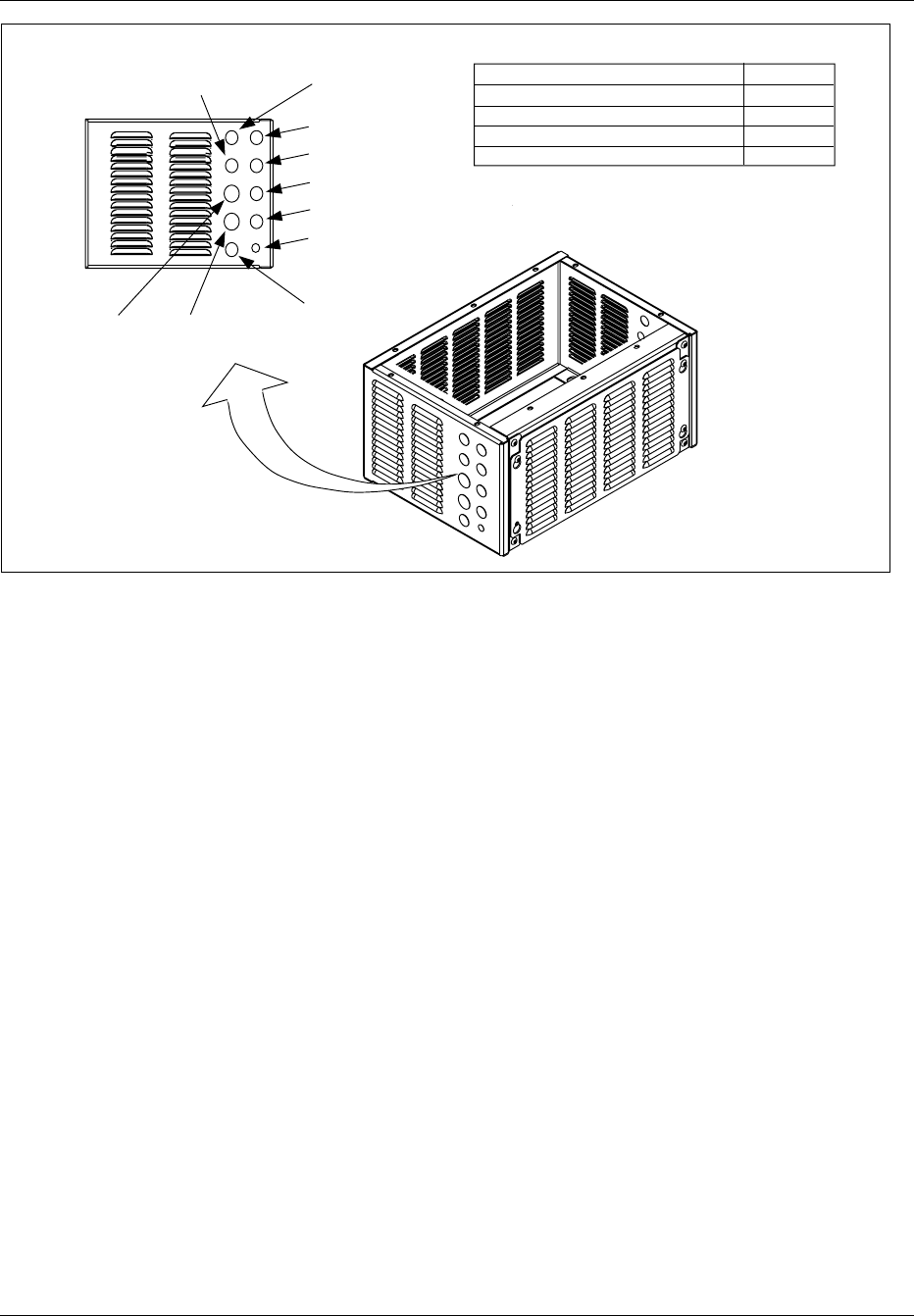
Installation
Antenna 3
Primary 2Primary 1
HOLE DIAMETERS
Primary 1 and 2
Antennas, T1 Line
Power
Cabinet Ground
35.05
28.70
28.70
12.70
Antenna 2
Antenna 1
Antenna 4
AC Power
DC Battery
Back-Up
T1 Line
Cabinet
Ground
Right Side
mm inches
1.38
1.13
1.13
.50
Figure 4-13. Pedestal Mount
4-30 1/1551-EN/LZB 119 3312 Uae Rev PA4 1998-10-05
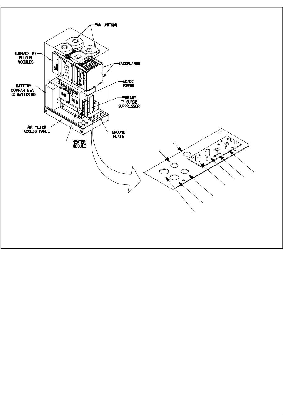
Installation
Antenna 4
Antenna 3
Antenna 2
Antenna 1
AC Power
External
Battery
T1/PCM
Primary 1
Primary 2
Note: Conduit openings in I/O plate fit 3/4" and 1"
liquid-tight flexible conduit.
Figure 4-14. Cabinet I/O Plate
1/1551-EN/LZB 119 3312 Uae Rev PA4 1998-10-05 4-31
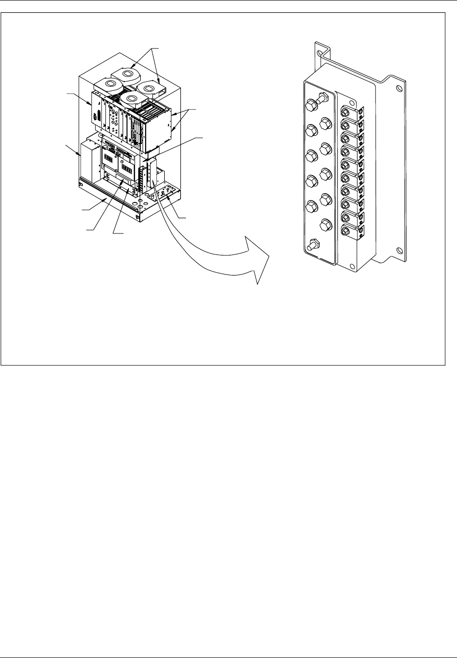
Installation
PCM (T1/E1) Primary Surge Suppressor
12345
PCM Secondary
Surge Suppressor
Air Filter
Access Panel
Subrack
Heater
Ground
Plate
Fans (4)
Subrack with
equipment
units Backplanes
AC/DC
Power
Battery
compartment
(2 batteries)
Figure 4-15. Cabinet Surge Suppressor
9.4.2 Pole Mount Cable Installation
1. Route the antenna cable and T1(E1) conduit into bottom of cabinet.
The T1(E1) conduit is terminated at the I/O plate.
2. Slide heat shrink tubing over cable connector and connect the
antenna jumpers to the antenna surge suppressors on I/O plate.
3. Apply heat to heat-shrink tubing to seal connector.
4. Route T1(E1) cables through conduit connect the cables to the
surge protector. Refer to Table 4-5 on page 4-33
5. After all cables are installed, turn on the AC power.
6. Watch the LEDs on each board and verify the unit is operating
properly. Consult the troubleshooting part of the Installation and
Maintenance manual for units that are malfunctioning.
4-32 1/1551-EN/LZB 119 3312 Uae Rev PA4 1998-10-05
Installation
Table 4-5. T1 Input Connections to Primary Surge Suppressor
Terminal No. T1 Cable Pair No. Wire
1 (white) In 1 Tip
1 (orange) In 1Ring
2 (white) In 2Tip
2 (orange) In 2 Ring
3 (white) Out 1Tip
3 (orange) Out 1 Ring
4 (white) Out 2Tip
4 (orange Out 2Ring
5 (white) Not used
5 (orange) Not used
Table 4-6. T1 Output Connections to Primary Surge Suppressor
RJ45 Conn Pin No. T1 Cable Pair No. Wire
J1 5In 1 Tip
J1 4 In 1 Ring
J1 1In 2Tip
J1 2In 2Ring
J2 5Out 1Tip
J2 4Out 1Ring
J2 1 Out 2 Tip
J2 2Out 2Ring
9.4.3 Wall Mount Cable Installation
1. Route the antenna cable and T1(E1) conduit into bottom of cabinet.
The T1(E1) conduit is terminated at the I/O plate.
2. Slide heat shrink tubing over cable connector and connect the
antenna jumpers to the antenna surge suppressors on I/O plate.
3. Apply heat to heat-shrink tubing to seal connector.
4. Route T1(E1) cables through conduit connect the cables to the
surge protector.
5. After all cables are installed, turn on the AC power.
6. Watch the LEDs on each board and that the unit is operating
properly. Consult the troubleshooting part of the Installation and
Maintenance manual for units that are malfunctioning.
1/1551-EN/LZB 119 3312 Uae Rev PA4 1998-10-05 4-33
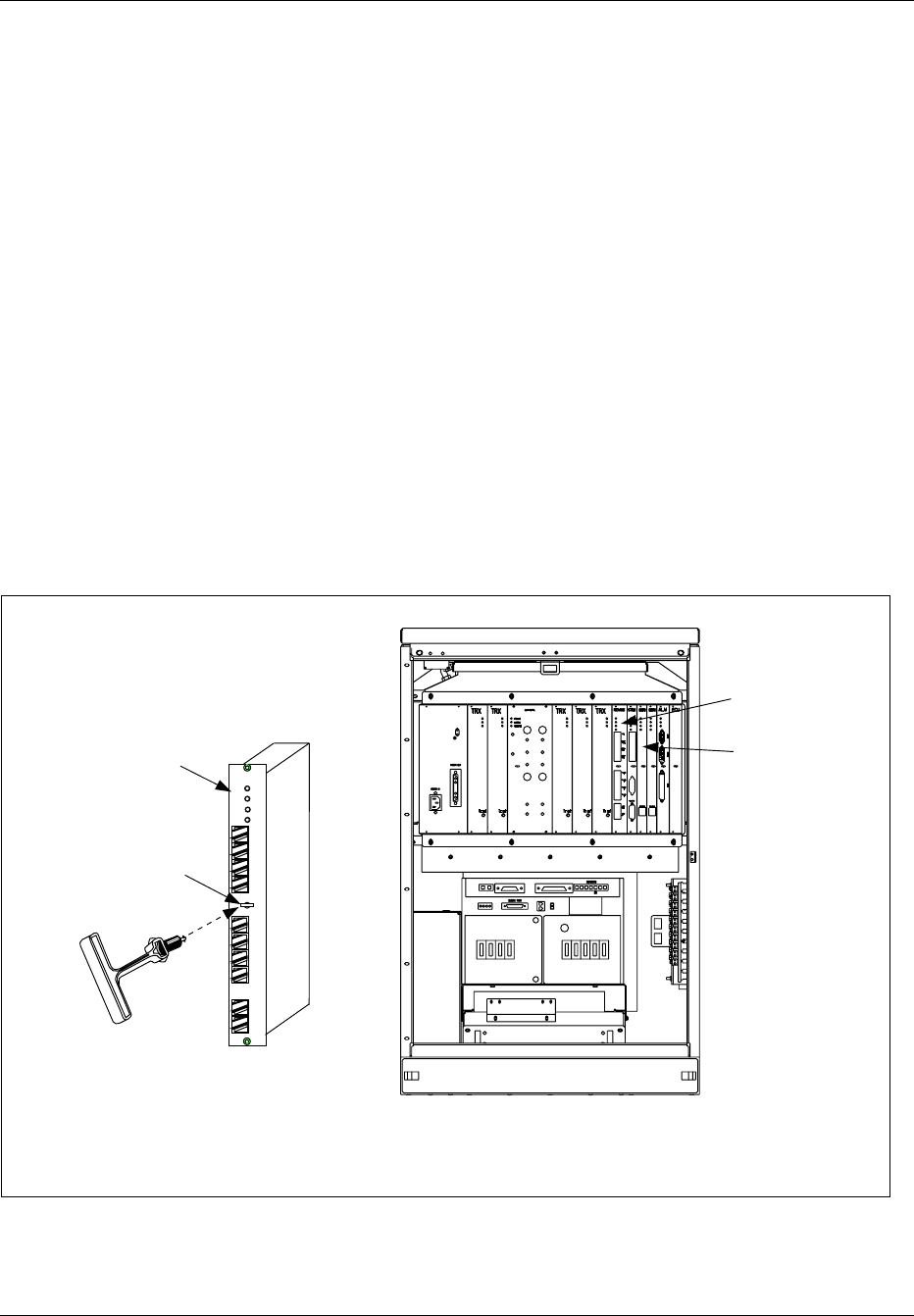
Installation
9.4.4 Roof Mount Cable Installation
Cabling of the roof mounted cabinet depends on the type of mounting kit
being used. Any of the three mounting kits, pedestal, pole, or wall, may be
used for the roof mount. Based on which mounting kit used, follow the
cabling instructions for that kit.
10 Setting the Unit Switches
Before the RBS 884 Micro (1900 MHz) is powered up, the REMUX and
EMRPM switches must be set. This section describes the procedure for
setting the REMUX and EMRPM switches.
Prior to starting, review electrostatic discharge instructions in Section 3 on
page 4-5.
For information on removing the REMUX or EMRPM, refer to the
Hardware Replacement RBS 884 Micro (1900 MHz) part of this document.
The units are shown in Figure 4-16 on page 4-34.
EMRPM
Unit
PCM
Test
TLINK
1
TLINK
2
TLINK
3
TLINK
4
REMUX
Power
Error
V24
PCM
Prim
PCM
Sec
AFS
In
AFS
Out
Status 1
Status 2
Slot for Unit
Extractor Tool
REMUX
Unit
REMUX
Unit
NOTE: Before inserting Unit Extractor Tool,
remove extractor hole plug and set aside. Reinstall
plug after unit removal.
Figure 4-16. Cabinet Units for Switch Settings (Example with a Main Cabinet)
4-34 1/1551-EN/LZB 119 3312 Uae Rev PA4 1998-10-05

Installation
10.1 Prerequisites and Tools
10.1.1 Prerequisites
The following site specific data for setting the switches on the units must be
available in the Configuration Data in the Site Installation Documentation:
•PCM line impedance
•PCM primary line specification (length or attenuation)
•PCM secondary line specification (length or attenuation)
•PCM primary line code and frame mode
•PCM secondary line cascading
•Control Signaling Link (CLC) extraction time slot
•PCM jitter and wander limit
•Frequency
10.1.2 Tools
The tools shown in Table 4-7 on page 4-35 are required for setting the
switches on the units:
Table 4-7. Tools for setting the Unit Switches
Product Number Description
LYB 250 01/14 ESD Wrist Strap and Cable
LTT 601 82 From Torque Wrench set:
- Torque Wrench for torque 0.6 Nm
(to use with the Torx bit TX10
- Torx bit TX10
(for the unit screws)
LTD 117 02 and
LTD 117 12
Unit Extractor Tool (Handle + Button)
Small screwdriver, pen, or simular tool to set switches
1/1551-EN/LZB 119 3312 Uae Rev PA4 1998-10-05 4-35
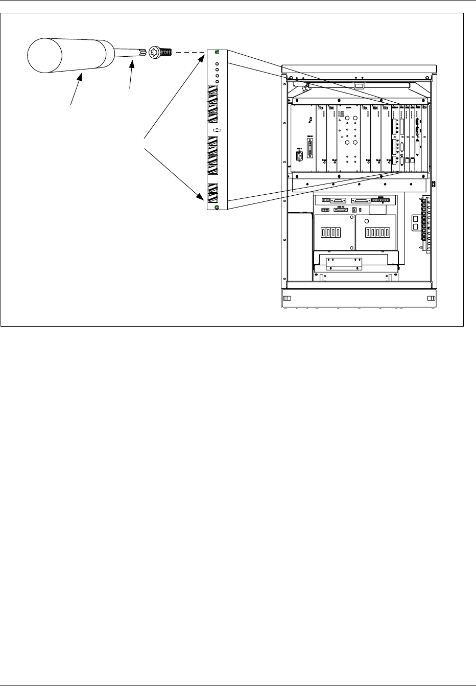
Installation
Torx Bit T10
Torque Wrench
Unit Screws
REMUX
Power
Error
V24
PCM
Prim
PCM
Sec
AFS
In
AFS
Out
Status 1
Status 2
Figure 4-17. Torque Wrench with Torx TX8
10.2 REMUX Switch Settings
1. Attach the ESD strap to your wrist and connect the free end of the
strap cable to an appropriate ground conductor in the cabinet.
2. Use the torque wrench with the Torx TX10 to loosen the top and
bottom screws on the front of the REMUX unit.
Note: Do not touch any components or connector pins on
a circuit board.
3. Remove the REMUX unit from the cabinet using the extractor tool
as shown in Figure 4-16 on page 4-34. Save the extractor hole plug
and replace plug after installing the REMUX unit.
4. Locate the 8-pole dip switch at the top front of the REMUX unit.
5. Set the unit to the PCM line impedance by setting the switches as
shown in Figure 4-18 on page 4-37. The line impedance can be found
in the Configuration Data in the Site Installation Documentation.
4-36 1/1551-EN/LZB 119 3312 Uae Rev PA4 1998-10-05
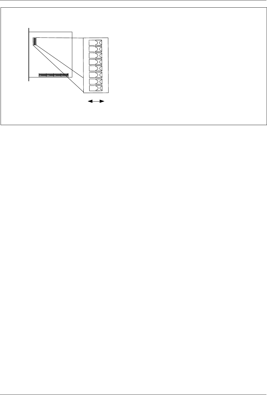
Installation
12345678
ON
10
Top
12345678
ON
Front Line Impedance Switch Settings (1-8)
75 ohm (E1) 0111 1101
100 ohm (T1) 1011 1110
120 ohm (E1) 0000 0000
REMUX Boards
ROF 367 211/3
ROF 367 211/1
ROF 367 211/3
PCM Line Impedance
Note: The example shows the REMUX set for 120 ohm line impedance (E1)
Figure 4-18. Setting the PCM Line Impedance
6. Locate the 32-pole dip switch at the bottom of the REMUX unit.
Note: When a dip switch is in its lower position (with the
REMUX board oriented as shown in the following
figures), the value is always 0 (zero) regardless of
what is written on the switch.
7. Check with the Configuration Data in the Site Installation
Documentation to determine whether the settings for the PCM
Primary line are decided by the length, attenuation, or impedance of
the line. Set the switches for the appropriate use as follows:
•If line length is used (T1 Short Haul), see Figure 4-19 on
page 4-38.
•If impedance is used (for E1 transmission, and T1 FCC
(Federal Communications Commission) part 68, option A),
see Figure 4-20 on page 4-38.
Note: For distances exceeding 40 meters, customer
supplied Channel Service Units (CSU) should be
used.
1/1551-EN/LZB 119 3312 Uae Rev PA4 1998-10-05 4-37
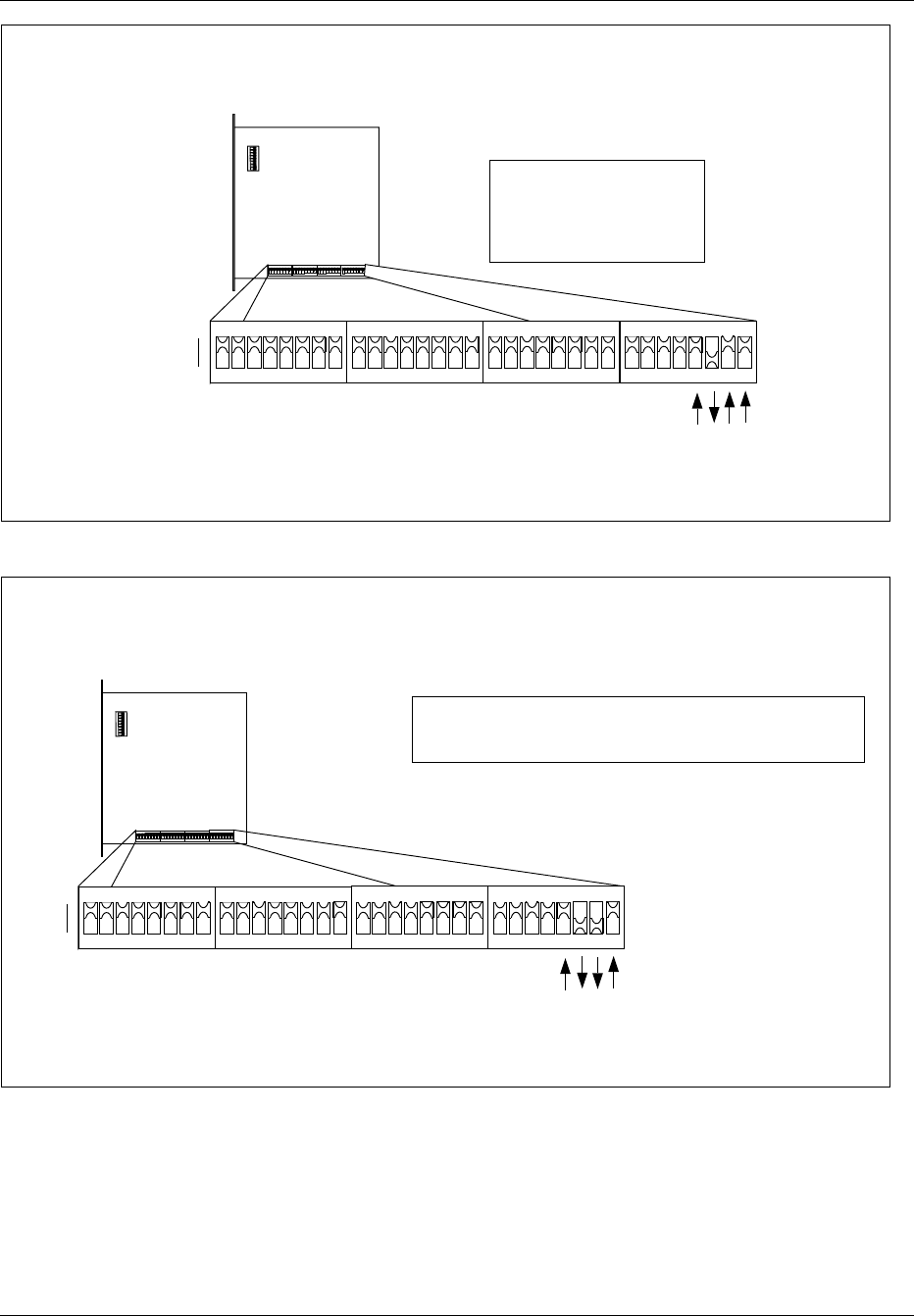
Installation
PCM Primary Line Specification for T1 Short Haul (SH)
Top
12345678
ON
Front
1
0
1 0 1 1
0 to 40 meters => 1011
40 to 80 meters => 1100
80 to 120 meters => 1101
120 to 160 meters => 1110
160 to 200 meters => 1111
Line Length
(REMUX boards ROF 367 211/1, /3)
The example shows the REMUX set for a T1 Short Haul line
up to 40 meters in length, connected to PCM Primary.
Note:
Figure 4-19. Settings for the PCM Primary Line Specification, T1 Short Haul
Note: The example shows the REMUX set for an E1 line with 120 ohm impedance, connected to PCM Prim.
1
0
1 0 0 1
Top
12345678
ON
Front
PCM Primary Line Specification for E1 and T1
75 ohm (E1) => 1000 (ROF 367 211/3)
120 ohm (E1) => 1001 (ROF 367 211/3)
100 ohm (T1 FCC part 68, opt A) => 1010 (ROF 367 211/1)
Line Impedance
Figure 4-20. Settings for the PCM Primary Line Specification, E1 and T1
8. Check with the Configuration Data in the Site Installation
Documentation to determine whether the settings for the PCM
4-38 1/1551-EN/LZB 119 3312 Uae Rev PA4 1998-10-05
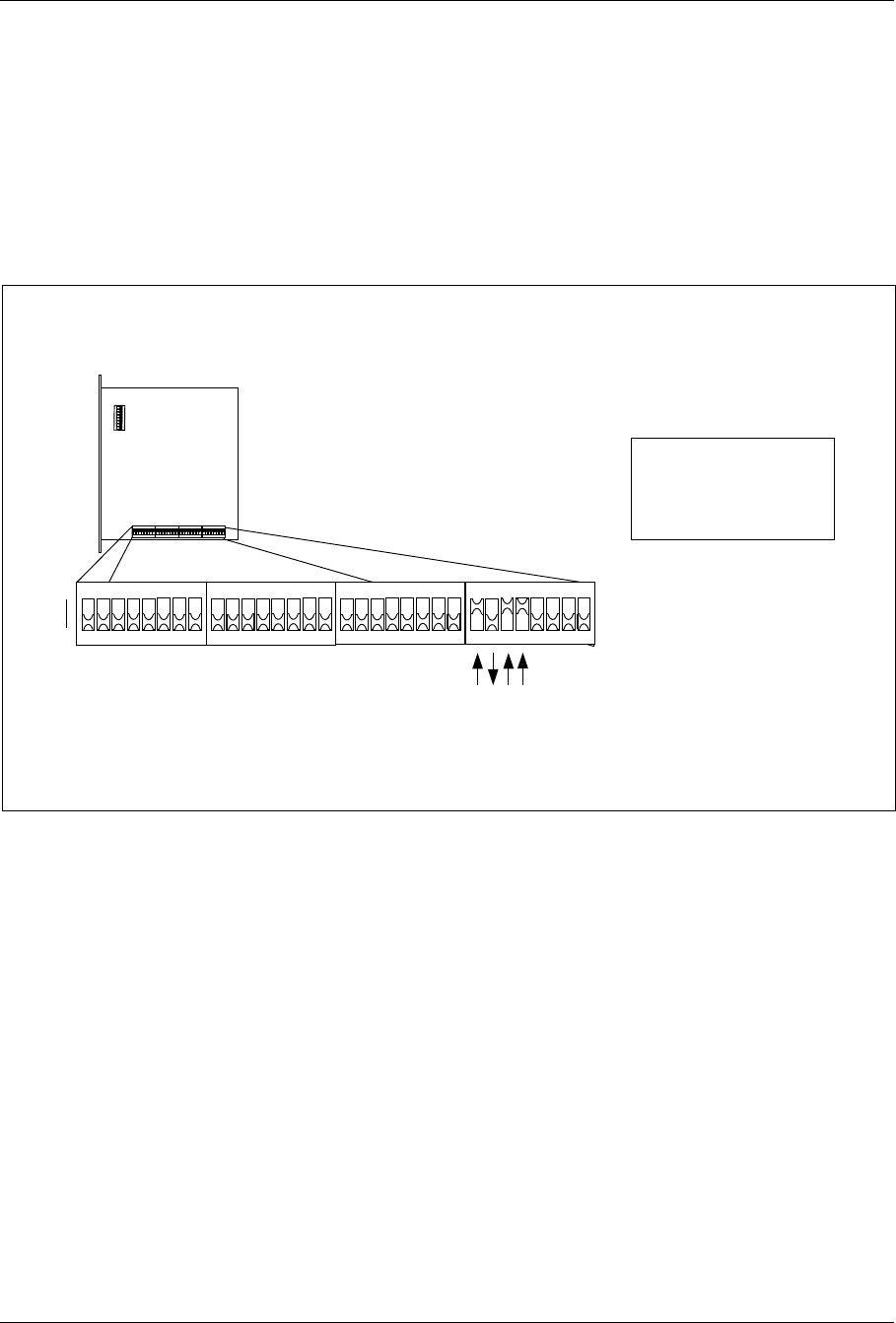
Installation
Secondary line are decided by the length, attenuation, or impedance
of the line. Set the switches for the appropriate use as follows:
•If line length is used (T1 Short Haul), see Figure 4-21 on
page 4-39.
•If impedance is used (for E1 transmission, and T1 FCC part
68, option A), see Figure 4-22 on page 4-40.
Note: For distances exceeding 40 meters, customer
supplied CSUs should be used.
1
0
1 0 1 1
Top
12345678
ON
12345678
ON
12345678
ON
12345678
ON
12345678
ON
Front
PCM Secondary Line Specification for T1 Short Haul (SH)
The example shows the REMUX set for a T1 Short Haul line
up to 40 meters in length, connectod to PCM Secondary.
Note:
0 to 40 meters => 1011
40 to 80 meters => 1100
80 to 120 meters => 1101
120 to 160 meters => 1110
160 to 200 meters => 1111
Line Length
(for REMUX boards
ROF 367 211/1, /3)
Figure 4-21. Settings for the PCM Secondary Line Specification, T1 Short Haul
1/1551-EN/LZB 119 3312 Uae Rev PA4 1998-10-05 4-39
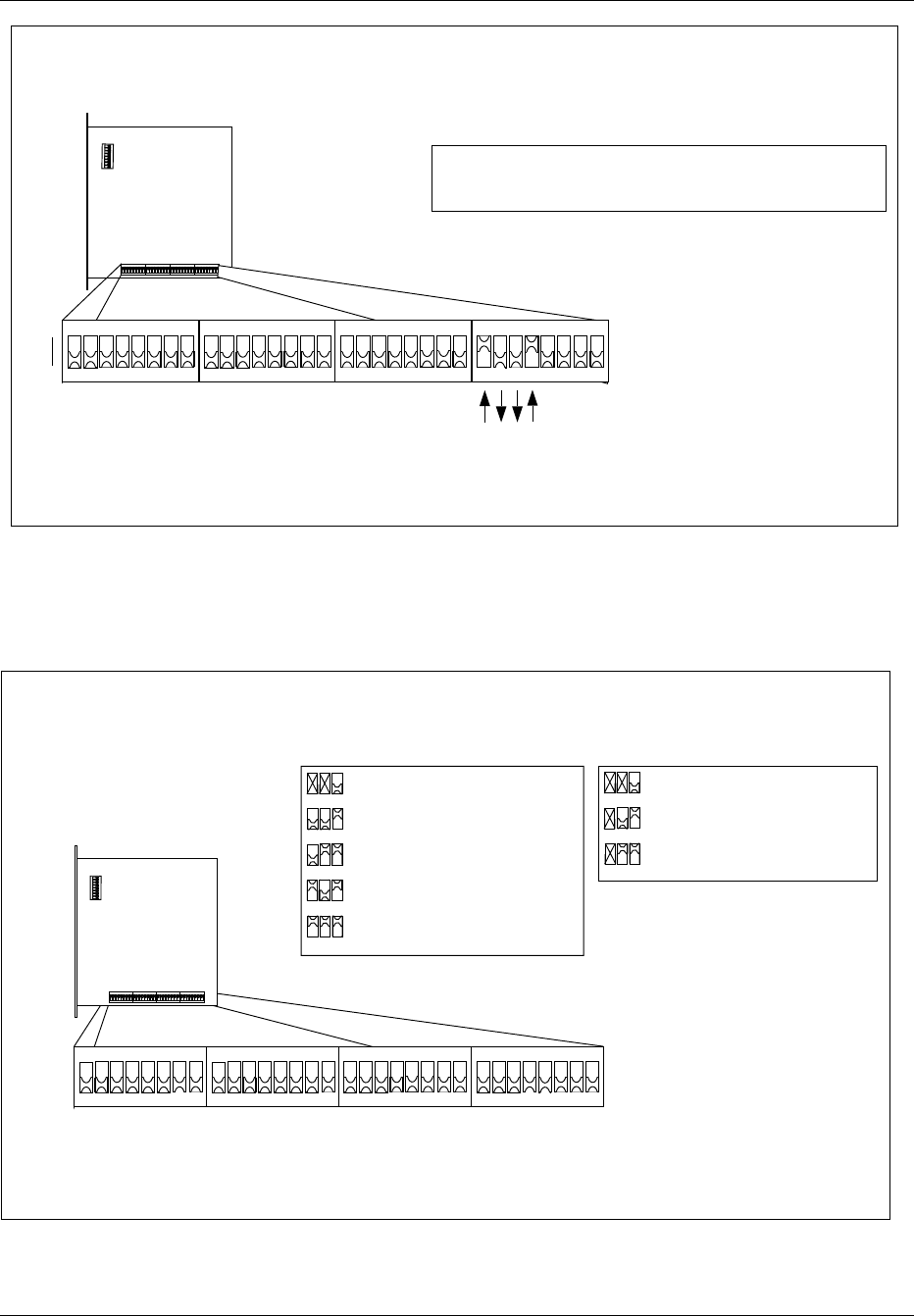
Installation
Top
12345678
ON
12345678
ON
12345678
ON
12345678
ON
12345678
ON
Front
1
0
1 0 0 1
PCM Seconday Line Specification for E1 and T1
Note: The example shows the REMUX set for an E1 line with 120 ohm impedance, connected to PCM Secondary.
Line Impedance
75 ohm (E1)
120 ohm (E1)
100 ohm (T1 FCC part 68, opt A)
=> 1000 (ROF 367 211/3)
=> 1001 (ROF 367 211/3)
=> 1010 (ROF 367 211/1)
Figure 4-22. Settings for the PCM Secondary Line Specification, E1 and T1
9. Set the PCM primary line code and frame mode, as shown in Figure
4-23 on page 4-40, in accordance with the Configuration Data in the
Site Installation Documentation.
Top
12345678
ON
12345678
ON
12345678
ON
12345678
ON
12345678
ON
Front
PCM Primary Line Code and Frame Mode
The example shows the REMUX set for automatic adaptation to line code
and frame mode on the line connected to PCM Primary (T1 or E1).
Note:
= Alternate Mark Inversion (AMI)
and Super Frame
= Bit 8 Zero Substitute (B8ZS)
and Super Frame
= Alternate Mark Inversion (AMI)
and Extended Super Frame
= Bit 8 Zero Substitute (B8ZS)
and Extended Super Frame
= Automatic Adaptation to PCM
(X = don’t care)
1
2
4
1
2
4
1
2
4
1
2
4
1
2
4
T1
= Double Frame (DF)
= Cyclic Redundancy Check
(CRC) Multi Frame
= Automatic Adaptation to PCM
(X = don’t care)
1
2
4
1
2
4
1
2
4
E1
Figure 4-23. Setting for PCM Primary Line Code and Frame Mode
4-40 1/1551-EN/LZB 119 3312 Uae Rev PA4 1998-10-05
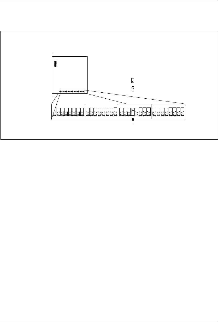
Installation
10. Set the switch to enable or disable the PCM secondary line for
cascading, as shown in Figure 4-24 on page 4-41 in accordance with
the Configuration Data in the Site Installation Documentation.
= Cascading enabled
= Cascading disabled
Top
12345678
ON
Front
PCM Secondary Line Cascading
Note: The example shows the REMUX set to enable the PCM Secondary line for cascading.
Figure 4-24. Enabling/Disabling the PCM Secondary Line for Cascading
11. For an E1 PCM line, select the time slot (TS) for Control signaling
Link (CLC) extraction, as shown in Figure 4-25 on page 4-42 in
accordance with the Configuration Data in the Site Installation
Documentation.
1/1551-EN/LZB 119 3312 Uae Rev PA4 1998-10-05 4-41
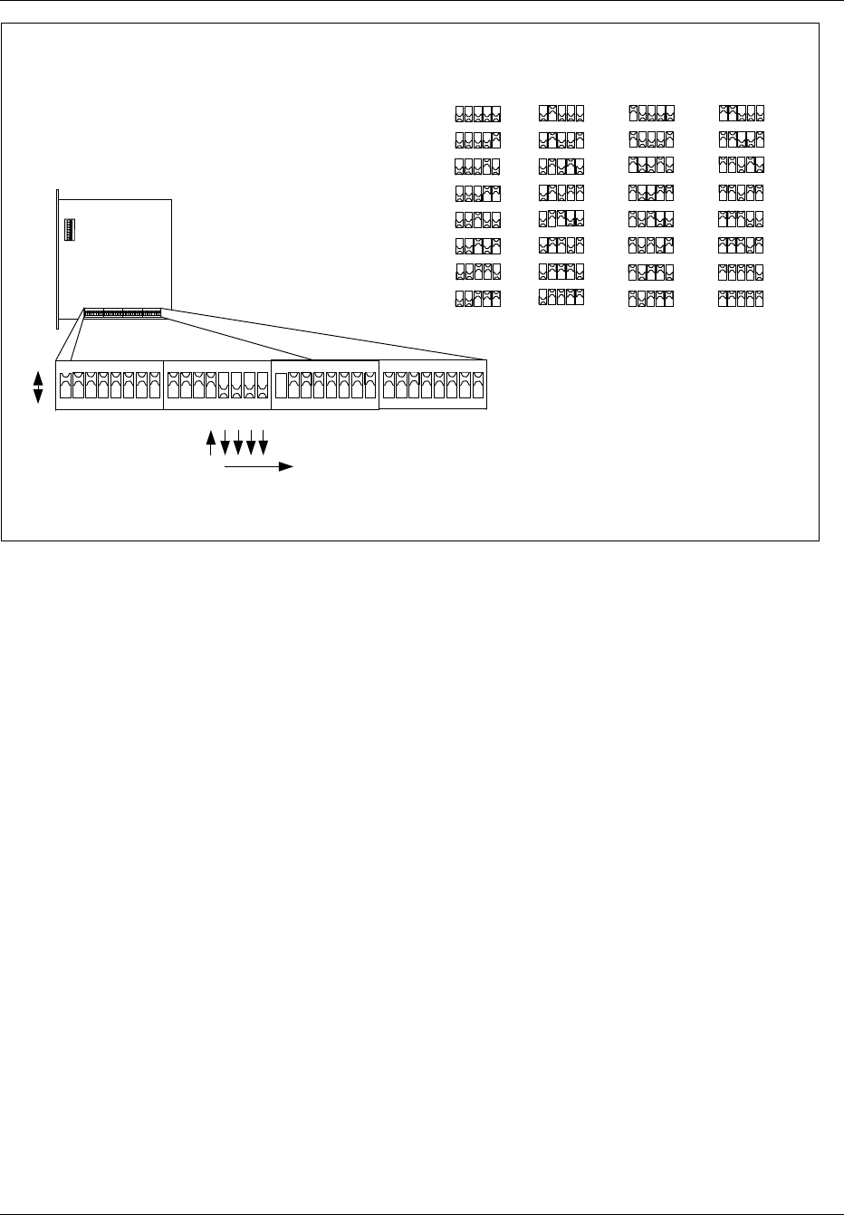
Installation
1
2
4
16 8
1
2
4
16 8
1
2
4
16 8
1
2
4
16 8
1
2
4
16 8
1
2
4
16 8
1
2
4
16 8
1
2
4
16 8
=TS 0
=TS 1
=TS 2
=TS 3
=TS 4
=TS 5
=TS 6
=TS 7
1
2
4
16 8
1
2
4
16 8
1
2
4
16 8
1
2
4
16 8
1
2
4
16 8
1
2
4
16 8
1
2
4
16 8
1
2
4
16 8
=TS 16
=TS 17
=TS 18
=TS 19
=TS 20
=TS 21
=TS 22
=TS 23
=TS 8
=TS 9
=TS 10
=TS 11
=TS 12
=TS 13
=TS 14
=TS 15
1
2
4
16 8
1
2
4
16 8
1
2
4
16 8
1
2
4
16 8
1
2
4
16 8
1
2
4
16 8
1
2
4
16 8
1
2
4
16 8
1
2
4
16 8
=TS 24
=TS 25
1
2
4
16 8
1
2
4
16 8
=TS 26
1
2
4
16 8
=TS 27
1
2
4
16 8
=TS 28
1
2
4
16 8
=TS 29
1
2
4
16 8
=TS 30
1
2
4
16 8
=TS 31
Dip switch values 0 - 31 = TS 0 - 31
Normal timeslot is TS 16
Top
12345678
ON
Front
Timeslot 16 (TS 16)
16
1
0
1
2
4
16 8
CLC Extraction Timeslot for E1
Note: The example shows the selection of timeslot 16 for CLC extraction (for an E1 line).
Figure 4-25. Setting the CLC Extraction Timeslot for E1
12. For a T1 PCM line, select the time slot (TS) for Control signaling
Link (CLC) extraction, as shown in Figure 4-26 on page 4-43, in
accordance with the Configuration Data in the Site Installation
Documentation.
4-42 1/1551-EN/LZB 119 3312 Uae Rev PA4 1998-10-05
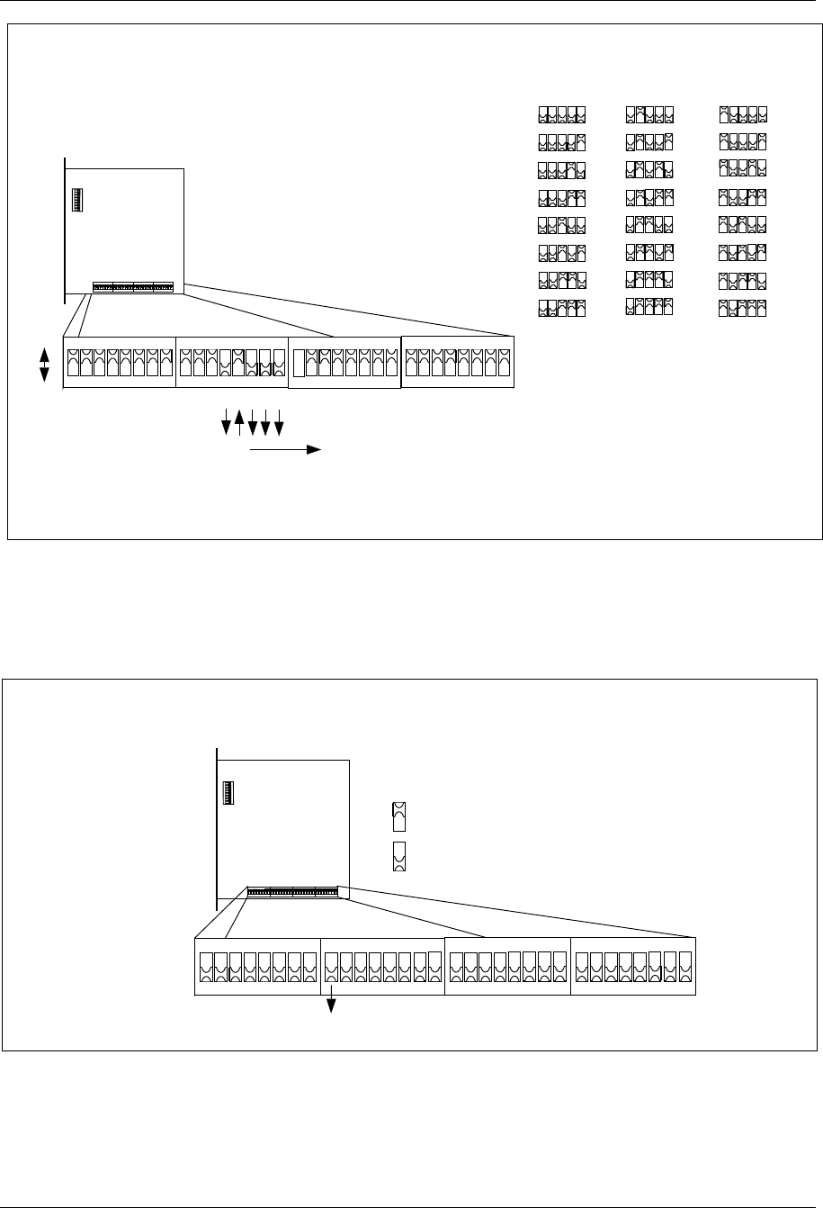
Installation
1
2
4
16 8
1
2
4
16 8
1
2
4
16 8
1
2
4
16 8
1
2
4
16 8
1
2
4
16 8
1
2
4
16 8
1
2
4
16 8
=TS 1
=TS 2
=TS 3
=TS 4
=TS 5
=TS 6
=TS 7
=TS 8
=TS 17
=TS 18
=TS 19
=TS 20
=TS 21
=TS 22
=TS 23
1
2
4
16 8
1
2
4
16 8
1
2
4
16 8
1
2
4
16 8
1
2
4
16 8
1
2
4
16 8
1
2
4
16 8
1
2
4
16 8
=TS 24
=TS 9
=TS 10
=TS 11
=TS 12
=TS 13
=TS 14
=TS 15
=TS 16
1
2
4
16 8
1
2
4
16 8
1
2
4
16 8
1
2
4
16 8
1
2
4
16 8
1
2
4
16 8
1
2
4
16 8
1
2
4
16 8
Timeslot 9 (TS 9)
8
1
0
1
2
4
16 8
Top
12345678
ON
Front
Dip switch values 0 - 23 = TS 1 - 24
Normal timeslot is TS 9
CLC Extraction Timeslot for T1
Note: The example shows the selection of timeslot 9 for CLC extraction (for an T1 line).
Figure 4-26. Setting the CLC Extraction Timeslot for T1
13. Set the jitter and wander limit for the PCM line for 138 Unit
Intervals (UI), as shown in Figure 4-27 on page 4-43 in accordance
with the Configuration Data in the Site Installation Documentation.
= J / W limit 138 Unit Intervals (UI)
= J / W limit 28 Unit Intervals (UI)
Top
12345678
ON
Front
PCM Jitter and Wander Limit
J/W = 138 UI
Figure 4-27. Setting the PCM Line Jitter and Wander Limit
14. Set the frequency of operation for 1900 MHz as shown in Figure
4-28 on page 4-44.
1/1551-EN/LZB 119 3312 Uae Rev PA4 1998-10-05 4-43
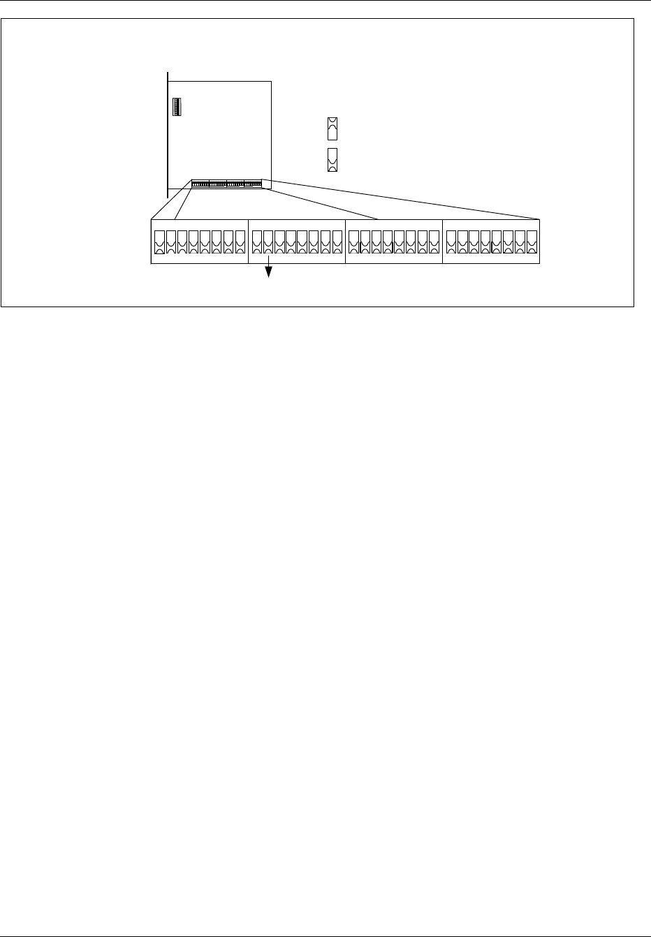
Installation
= 1900 MHz
= 800 MHz
Top
12345678
ON
Front
Frequency Selection
1900 MHz
Figure 4-28. Setting the Frequency of Operation
15. Carefully slide the REMUX unit back into the cabinet following the
guides, and push the unit firmly into the backplane connector.
16. Use the torque wrench with the Torx bit TX10 to tighten the top and
bottom screws on the front.
When turning the torque wrench until it slides, the screw is
tightened with the torque 0.6 Nm.
10.3 EMRPM Switch Settings
1. Keep the ESD strap attached.
2. Use the torque wrench with the Torx bit TX10 to loosen the top and
bottom screws on the front of one of the EMRPM units.
Note: Do not touch any components or connector pins on
a circuit board.
3. Remove the EMRPM unit from the cabinet using the extractor tool.
Save the extractor hole plug and replace plug after installing the
EMRPM unit.
4. Locate the dip switch and set the EMRPM address, as shown in the
following figure, depending on which cabinet is being configured.
Set the address as follows:
•Main Cabinet, set the EMRPM unit address to 1.
•Primary Cabinet 1, set the address to 3.
•Primary Cabinet 2, set the address to 5.
4-44 1/1551-EN/LZB 119 3312 Uae Rev PA4 1998-10-05
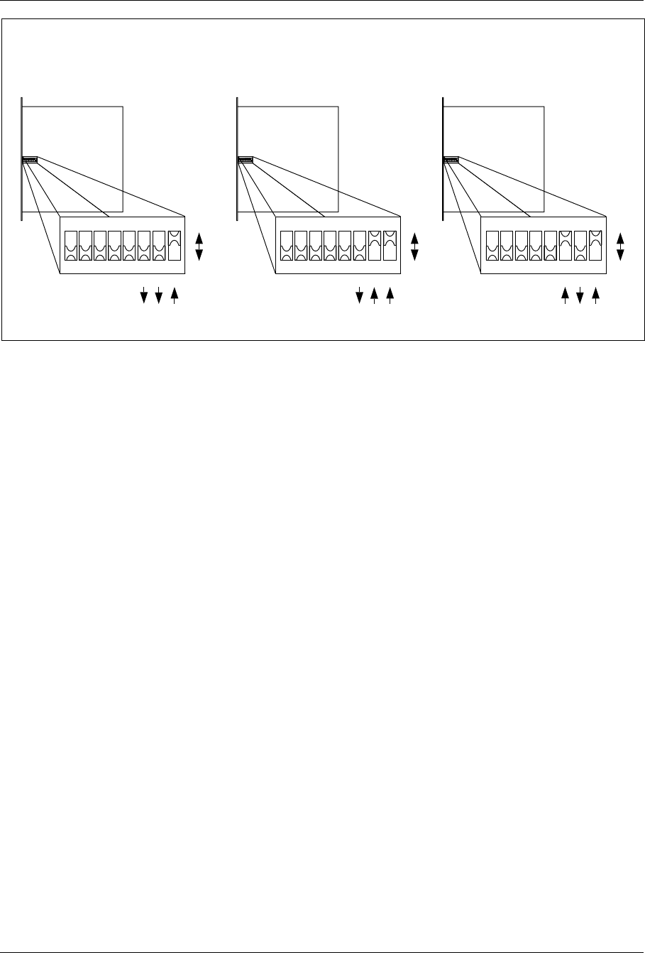
Installation
Main
Cabinet Primary 1
Cabinet Primary 2
Cabinet
Top
1
0
1
2
4
41
+= 5
Top
1
0
1
2
4
1= 1
Top
1
0
1
2
4
1
+= 3
2
Figure 4-29. EMRPM Address Setting
5. Carefully slide the EMRPM unit back into the cabinet following the
guides, and push the unit firmly into the backplane connector.
6. Use the torque wrench with the Torx bit TX10 to tighten the top and
bottom screws on the front.
7. Repeat the same steps for the other EMRPM unit.
11 External Cable Installation
This section describes the procedure for installing external cables for the
RBS 884 Micro (1900 MHz) cabinet.
Each cabinet arrives on site with internal cables pre-installed. These cables
are described in the Internal Cables appendix. All other cables must be
connected after the cabinets have been installed.
Information for optional cables and different site configurations is also
described in Section 17 on page 4-64.
Note: Cable routing depends on the number of sectors, number of
cabinets, and the number of antennas. Refer to the System
Description for additional information on RBS 884 cabinet
cabling. Also, the Configuration Data section in the Site
Installation Documentation contains information about the
actual site, cabinets, and antenna systems.
To simplify cable installation and troubleshooting, external cables are
labeled with connection point information.
1/1551-EN/LZB 119 3312 Uae Rev PA4 1998-10-05 4-45
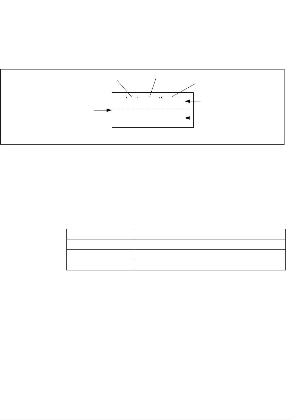
Installation
Intercabinet cables are labeled at each end. External cables are labeled at
the cabinet end only.
An example of a label attached to an intercabinet cable is shown in Figure
4-30 on page 4-46.
Intercabinet cables are provided in cabling kits.
Main - REMUX - TLINK1
Aux1 - CONN - TL1
The label is folded here
around the cable tag
Cabinet Name Unit Name Connector Name
Connection Point at this
end of the cable
Connection Point at the other
end of the cable
Figure 4-30. Example of an Intercabinet Cable Label
11.1 Required Materials and Tools
11.1.1 Materials
The cabling kits used with the cabinets are shown in Table 4-8 on page
4-46.
Table 4-8. External Cabinet Cables
Product Number Description
NTM 201 1807 External Cabinet Cable Set
RPM 113 1443/2 ANP unit to TRX unit
TSR 952 144/3 ANP unit to Antenna I/O connector plate
Install the cables in the order they appear in the table enclosed with each
cable kit.
Note: In the figures in this section, the cables are drawn as much as
possible in the way they have to be routed in reality. For
instance, the cables must not cover any TRX.
11.1.2 Tools
The Torque Wrench set LTT 601 82 including the Torque Wrench (for
torque 0.6 Nm) with the SMA tool is all that is required.
Initially, hand-tighten all SMA connectors. Thereafter, fully tighten using
the torque wrench with the SMA tool, as shown in Figure 4-31 on page
4-47.
4-46 1/1551-EN/LZB 119 3312 Uae Rev PA4 1998-10-05
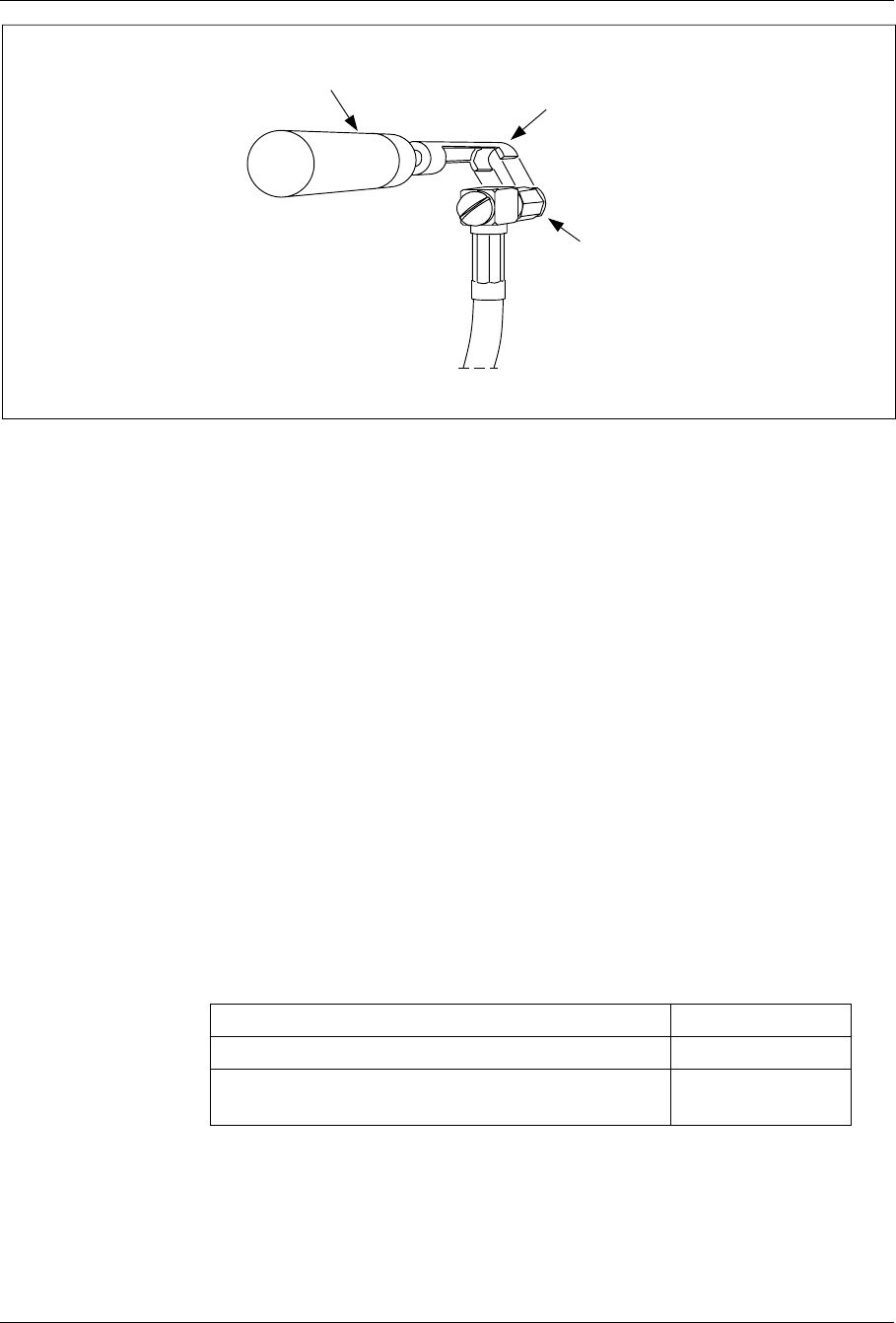
Installation
Torque Wrench SMA Tool
SMA Connector
Figure 4-31. Using the Torque Wrench with the SMA Tool
Turn the torque wrench until it slides to tighten connector to 0.6 Nm.
11.2 Antenna Connections
See the Cable Way Drawing or the Situating Plan in the Site Installation
Documentation on where the cables are located.
The jumper cables or the feeders are labelled with the connector name (for
example ’ANT 1’). See the Antenna Cable Distribution Diagram in the
Site Installation Documentation for more information about the connection
to the cabinets.
11.3 ANP/RFTL Connections
11.3.1 Tools
The tools required for installation of ANP/RFTL units and cables are
shown in the Table 4-9 on page 4-47, Figure 4-32 on page 4-48, Figure
4-33 on page 4-49, and Figure 4-34 on page 4-49.
Table 4-9. Tools for ANP/RFTL Unit and Cable Installation
Description Product Number
ESD Wrist Strap and Cable LYB 250 01/14
Unit Extractor Tool (Handle and Button) LTD 117 02 and
LTD 117 14
1/1551-EN/LZB 119 3312 Uae Rev PA4 1998-10-05 4-47
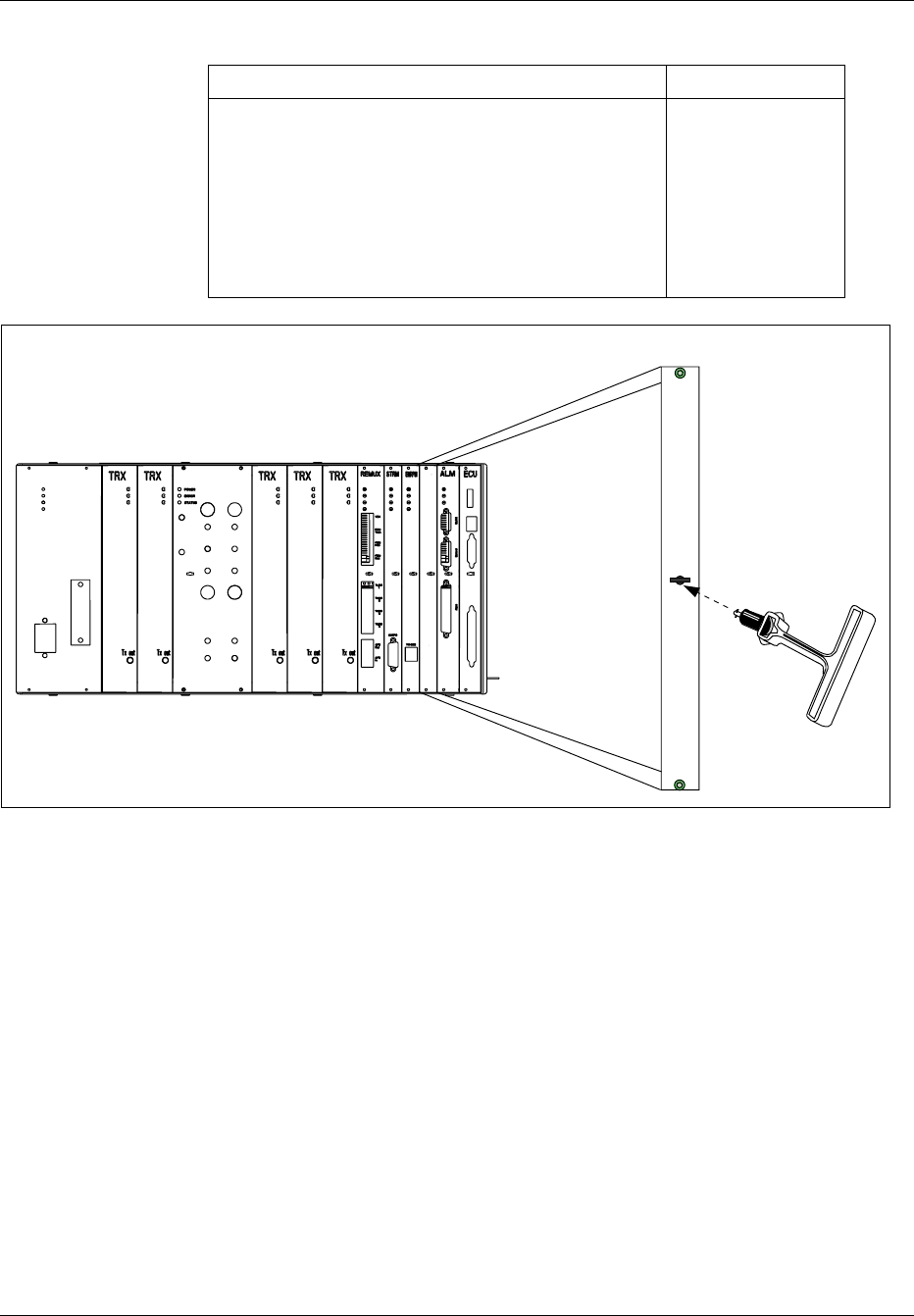
Installation
Table 4-9. Tools for ANP/RFTL Unit and Cable Installation (Continued)
Description Product Number
Torque Wrench set including:
- Torque Wrench for torque 0.6 Nm
(to use with the SMA tool and the torx bit TX10 or
TX8)
- Torx bit TX10 or TX8
(for circuit board screws)
- SMA tool
(for the coaxial cables)
LTT 601 82
ANP/RFTL
Figure 4-32. Unit Extractor Tool (extracting Blank Panel)
4-48 1/1551-EN/LZB 119 3312 Uae Rev PA4 1998-10-05
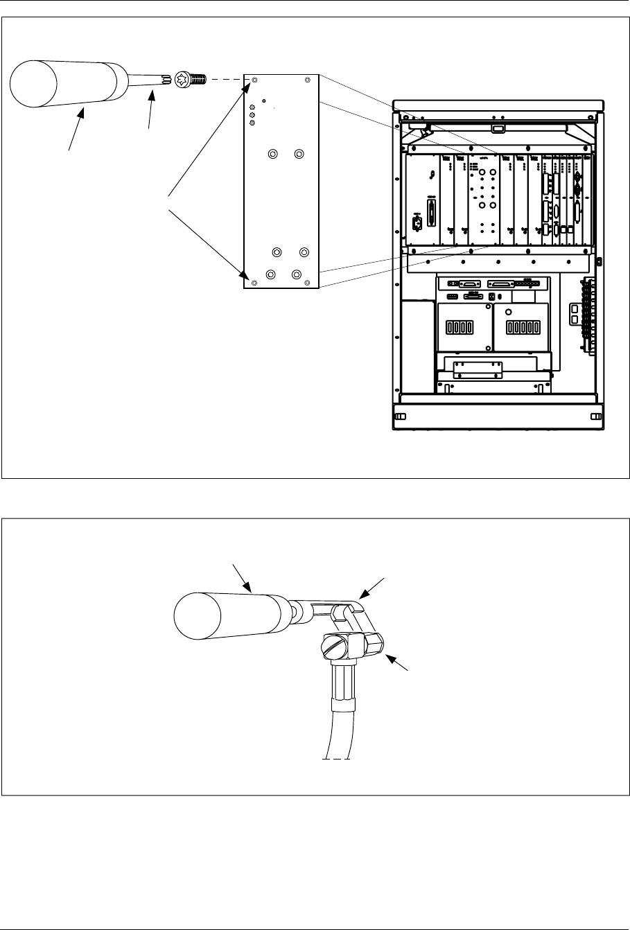
Installation
Torx Bit T10
or T8
Torque Wrench
Unit Screws
ANP/RFTL
Power
Error
Status
DPX
ANT 1 DPX
ANT 2
TX IN 1
TX IN 2
TX IN 3
TX IN 4
Figure 4-33. Torque Wrench with Torx TX8
Torque Wrench SMA Tool
SMA Connector
Figure 4-34. Torque Wrench with SMA Tool
1/1551-EN/LZB 119 3312 Uae Rev PA4 1998-10-05 4-49

Installation
11.3.2 Installation procedure
1. Attach the ESD strap to your wrist and connect the free end of the
strap cable to an appropriate ground conductor in the cabinet.
In Section 3 on page 4-5 there is more information about ESD.
2. Carefully slide the ANP/RFTL unit into the cabinet following the
guides. Push the unit firmly into the backplane connector.
3. Use the torque wrench with the Torx bit TX10 to tighten the
screws on the front.
Turn the torque wrench until it slides to tighten screws to 0.6 Nm.
4. Check that the green power LED on the unit is on and the red error
LED is off. If this is not the case, refer to the troubleshooting
procedure in the Maintenance part for detection of units suspected
to be faulty.
5. Connect the four ANP to TRX cables (RPM 113 1443/2) from the
“TX Out” connector on the TRX unit to the appropriate TX IN
connector on the ANP/RFTL unit. See Figure 4-35 on page 4-51
for the location of the connectors.
6. The ANP/RFTL unit has cable connections for two or four antennas
depending on the type of unit installed. Figure 4-35 on page 4-51
illustrates two antennas and Figure 4-36 on page 4-52 illustrates
four antennas. The cables are listed in Table 4-10 on page 4-52.
The cable numbers for either a two-antenna or four-antenna
configuration are the same. Install the antenna cables as follows:
– Connect the first cable to the RX/TX ANT 1 connector on the
front of the ANP/RFTL unit. Route the cable vertically down
into the horizontal cable tray below the subrack. Route the cable
to the right along the cable tray. Leaving the horizontal cable
tray, route the cable vertically down the right inside cabinet wall
into the vertical cable tray. From the vertical cable tray, route
the cable to the I/O connector plate at the base of the cabinet.
Connect the type N coaxial connector to the Antenna 1
connector and secure it by rotating the locking ring clockwise.
– Connect the second cable to the RX/TX ANT 2 connector on
the front of the ANP/RFTL unit. Route the cable the same as
the antenna 1 cable and connect in to the Antenna 2 connector
on the I/O plate.
– If a four antenna ANP/RFTL unit is installed, route antennas
three and four in the same way.
When attaching the cable connector to the connector on the unit,
hand-tighten as much as possible. Thereafter, fully tighten using
the torque wrench with the SMA tool.
Turn the torque wrench until it slides to tighten the connector to
0.6 Nm.
7. Report to the MSC.
4-50 1/1551-EN/LZB 119 3312 Uae Rev PA4 1998-10-05

Installation
The cabinets shown in the following figures are fully configured Main
Cabinets. The cabling is the same for Primary Cabinets (a Primary Cabinet
has a blank 12M and a CONN unit instead of the REMUX and the STRM
units).
ANP/RFTL
Power
Error
Status
DPX
ANT 1 DPX
ANT 2
TX IN 1
TX IN 2
TX IN 3
TX IN 4
Power
Error
Status
Power
Error
Status
Power
Error
Status
Power
Error
Status
Power
Error
Status
Tx out Tx out Tx out Tx out Tx out
Note: The TRX board in position 6 is used for DVER
I/O Connector Plate
Pos. 6
Antenna 2
Antenna 1
Cable Tray
Cable Tray
Figure 4-35. Antenna Cable Connections for a Cabinet Using Two Antennas
1/1551-EN/LZB 119 3312 Uae Rev PA4 1998-10-05 4-51
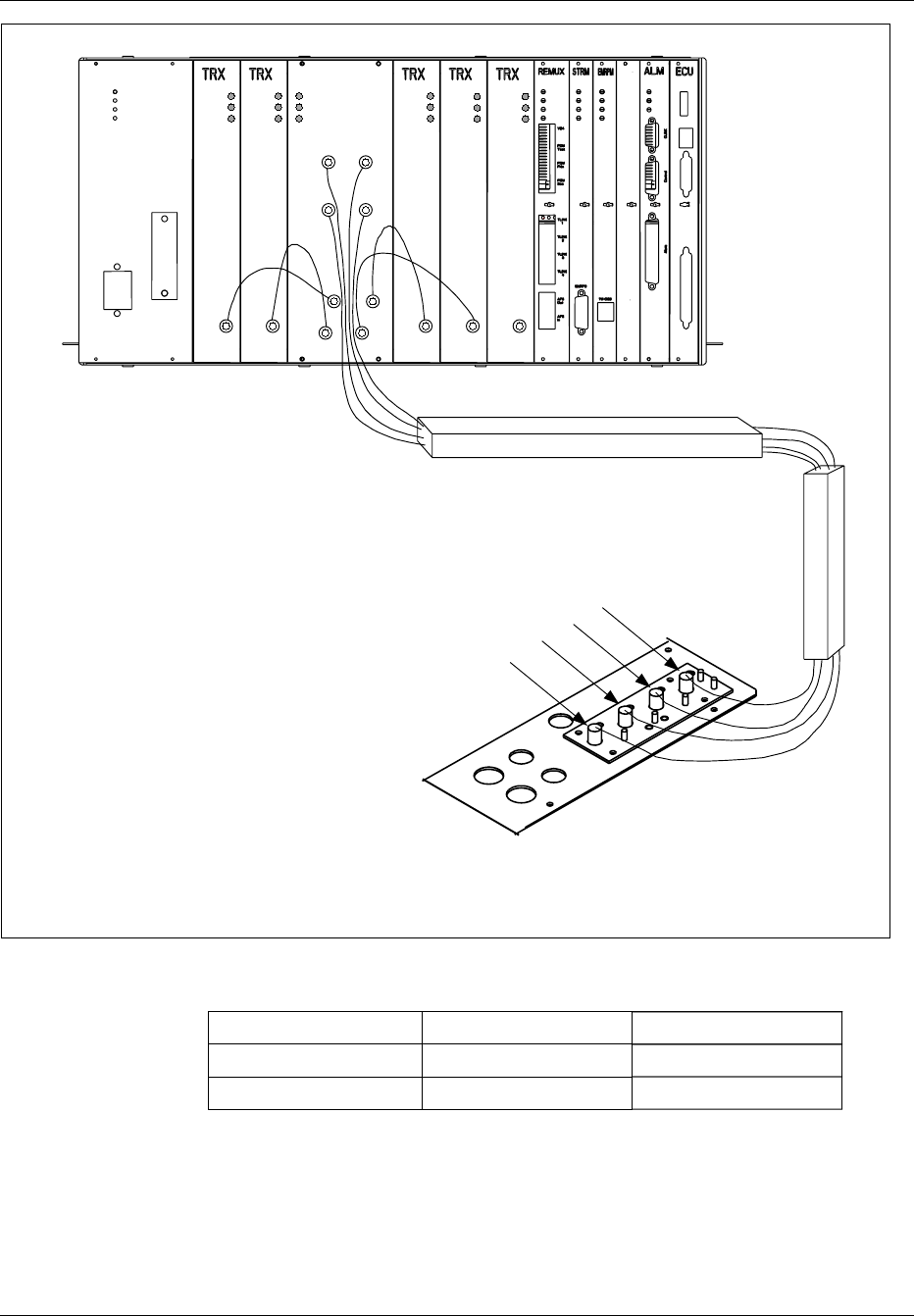
Installation
Note: The TRX board in position 6 is used for DVER
ANP/RFTL
Power
Error
Status
Power
Error
Status
Power
Error
Status
Power
Error
Status
Power
Error
Status
Tx out Tx out Tx out Tx out Tx out
Power
Error
Status
DPX
ANT 1 DPX
ANT 2
TX IN 1
TX IN 2
TX IN 3
TX IN 4
DPX
ANT 3 DPX
ANT 4
Pos. 6
I/O Connector Plate
Antenna 4
Antenna 3
Antenna 2
Antenna 1
Cable Tray
Cable Tray
Figure 4-36. Antenna Cable Connections for a Cabinet Using Four Antennas
Table 4-10. Cables for Two and Four Antenna Configurations
Cable Number Connector A Connector B
RPM 113 1443/2 TRX Unit ANP/RFTL Unit
TSR 952 144/3 ANP/RFTL Unit Antenna I/O Plate
4-52 1/1551-EN/LZB 119 3312 Uae Rev PA4 1998-10-05
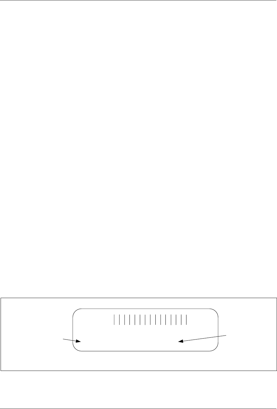
Installation
12 Site Inventory
To facilitate equipment replacement in the RBS cabinets, perform a site
inventory to identify all units delivered, including revision states. This
information is recorded in the Plant Specification found in the Site
Installation Documentation.
12.1 Prerequisites
12.1.1 Prerequisites
Complete the following activities before the site inventory is performed:
•Cabinet mounting
•Grounding
•Setting of switches
•Cable installation
12.2 Site Inventory Procedure
Site Information
1. Record the name of the site, date, and other relevant information for
each cabinet in the Site Installation Documentation,Plant
Specification, or follow your local procedure.
RBS Cabinet Units
2. Locate the product labels on all of the units in the cabinets. Each
unit has a product label stuck to its front panel, as shown in Figure
4-37 on page 4-53, indicating its product number and revision state.
A53047P963 95w03 A53
P/ KRC 121 10/4 R1A
Product
Number R-State
Figure 4-37. Unit Product Label
1/1551-EN/LZB 119 3312 Uae Rev PA4 1998-10-05 4-53

Installation
3. Record the product number, serial number, and R-state for each unit
in each of the cabinets in the Plant Specification (or any other site
inventory list). See Table 4-11 on page 4-54.
Table 4-11. RBS 884 Micro (1900 MHz) Units
Product Number Unit
HRB 104 13 1900 Micro Radio Base Station
ROF 137 2775 ECU Unit
ROA 119 3157/7 ALM
ROF 367 211/1 REMUX - (T1) 24 Channel
ROF 367 211/3 REMUX - (E1) 32 Channel
ROF 367 212/1 CONN
ROF 367 207/1 STRM
ROF 367 210/1 EMRPM
KRC 121 106/1 TRX
KRF 102 115/1 ANP/RFTL (2) Two Antenna (A+D)
KRF 102 115/2 ANP/RFTL (4) Four Antenna (A+D)
KRF 102 115/3 ANP/RFTL (2) Two Antenna (D+B+E)
KRF 102 115/4 ANP/RFTL (4) Four Antenna (D+B+E)
KRF 102 115/5 ANP/RFTL (2) Two Antenna (E+F+C)
KRF 102 115/6 ANP/RFTL (4) Four Antenna (E+F+C)
ROF 367 213/1 Dummy EMRPM
ROF 367 216/1 Dummy REMUX
ROF 367 217 Dummy TRX
BKV 301 457 Fan
13 Equipment Power Up
This section describes the procedure for applying AC power to each of the
RBS 884 Micro (1900 MHz) cabinets.
Note: Read the Safety Considerations (Section 2 on page 4-3) before
starting the power up procedure.
4-54 1/1551-EN/LZB 119 3312 Uae Rev PA4 1998-10-05

Installation
13.1 Prerequisites and Test Equipment
13.1.1 Prerequisites
The following activities must be completed before power can be applied to
the equipment cabinets:
•Installation of all cabinets
•Grounding of all cabinets
•Setting of switches in all cabinets
•Cabling of all cabinets
•AC voltage available on site, connected to the cabinets
13.1.2 Tools and Test Equipment
The following equipment is required for completing the electrical power
installation and for power-up testing:
•Tools for connecting the AC power cable to a line power access
point, if this is the local procedure
•Multimeter for checking supplied line voltage and polarity for DC
power.
13.2 Power-Up Procedure
AC Power Connection
1. Verify the AC CONNECTED lamp on the front panel of the AC/DC
box is ON.
2. Position the circuit breakers on the front panel of the AC/DC box to
ON in the following sequence. See Figure 4-38 on page 4-56 for the
location of the circuit breakers.
•Main
•PSU
•ECU
•FANS
1/1551-EN/LZB 119 3312 Uae Rev PA4 1998-10-05 4-55
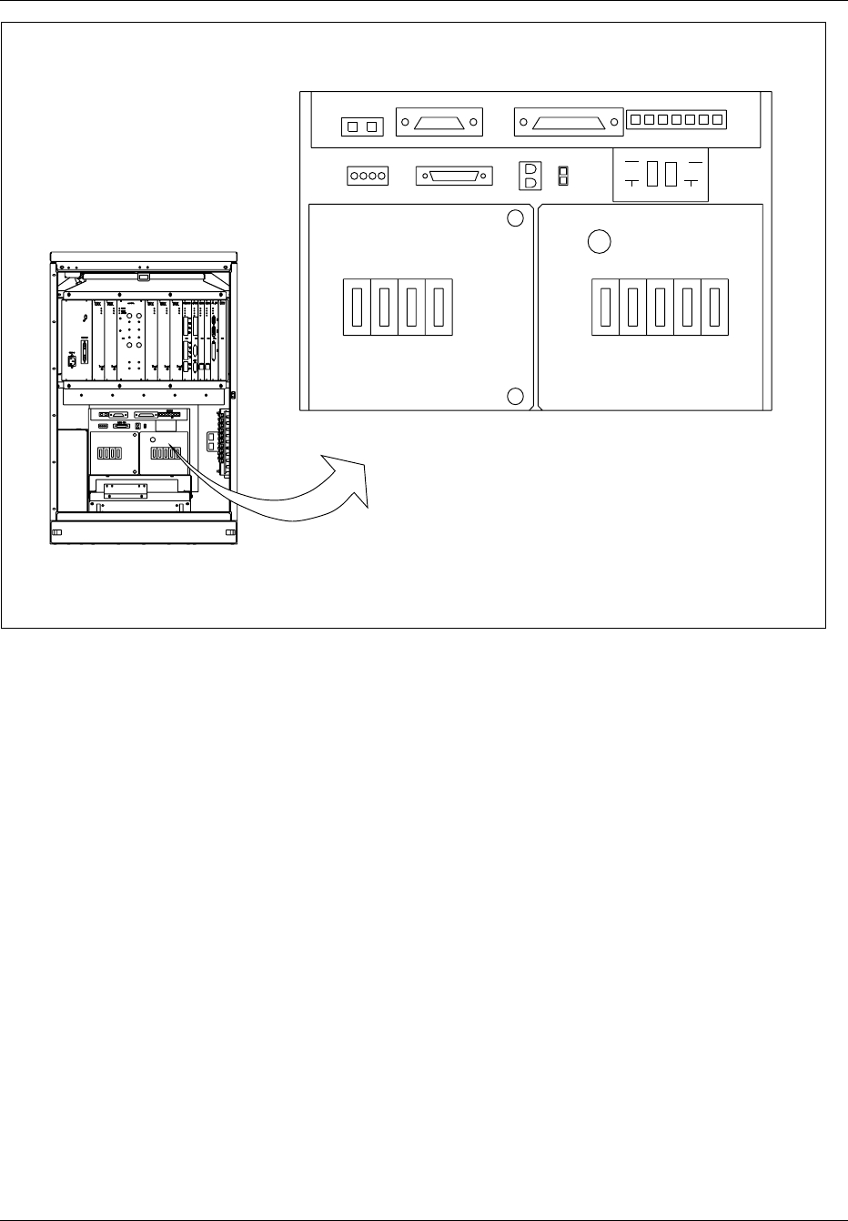
Installation
ALM CABLE ECU CABLE
SUBRK PWR
FAN PWR CSU
SENSORS
AC
CONNECTED
MAIN PSU MAIN
HTR BAT
HTR GFI
OUTLET
BAT ECU CSU FANS
BAT COMP
BAT
ALM DOOR
ALM
ON
OFF
Figure 4-38. Cabinet Circuit Breakers
3. After the above circuit breakers are on, the fans will start up fast and
drop back to a normal operating speed. Observe that for about 20
seconds after power-up, the red Error LEDs on all units in the
subrack flash at 3 Hz as the units perform internal self-tests.
4. Position the remainder of the circuit breakers to ON as follows:
•BAT
•MAIN HTR
•BAT HTR
•CSU (if customer-supplied CSU equipment is installed)
Note: Do not turn on the GFI OUTLET circuit breaker
unless performing maintenance on the
equipment.
Power-Up Test
5. After 20 seconds, verify that all fans at the top of the cabinet are
running. If not, refer to the troubleshooting procedure for detection
of units suspected to be faulty.
4-56 1/1551-EN/LZB 119 3312 Uae Rev PA4 1998-10-05
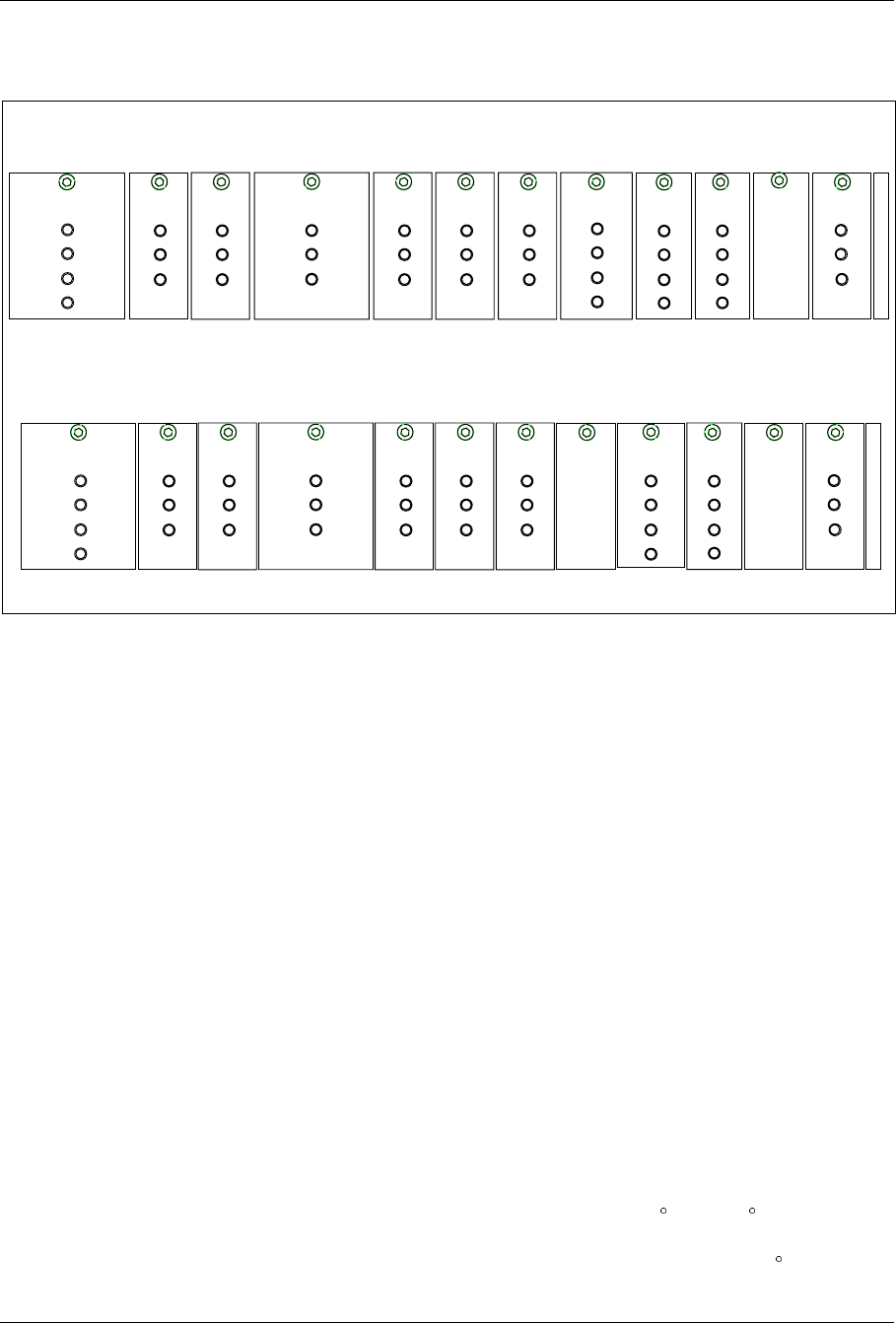
Installation
6. Check that the green Power Light Emitting Diode (LED) on each of
the units in the cabinet is on (see Figure 4-39 on page 4-57).
TRX
Power
Error
Status
REMUX
Power
Error
Status 1
Status 2
Power
Error
Status 1
EMRPM
Status 2
ALM
Power
Error
Status
TRX
Power
Error
Status
TRX
Power
Error
Status
TRX
Power
Error
Status
TRX
Power
Error
Status
ANP/RFTL
Power
Error
Status
Power
Error
Status 1
Status 2
STRM
PSU
AC Main
DC Output
Current Limit
Main Cabinet
Primary Cabinet
Power
Error
Status 2
Status 1
CONN
TRX
Power
Error
Status
Power
Error
Status 1
EMRPM
Status 2
ALM
Power
Error
Status
TRX
Power
Error
Status
TRX
Power
Error
Status
TRX
Power
Error
Status
TRX
Power
Error
Status
ANP/RFTL
Power
Error
Status
PSU
AC Main
DC Output
Current Limit
Figure 4-39. The Green Power LEDs and Red Error LEDs
7. If any of the green Power LEDs are off, replace the unit in
accordance with the Unit Replacement section in the Maintenance
part.
8. Check that none of the red Error LEDs is on (see Figure 4-39 on
page 4-57).
9. If any of the red Error LEDs are on or flashing continuously, replace
the unit in accordance with the Unit Replacement section in the
Maintenance part.
10. Repeat Step 1 on page 4-55 to Step 9 on page 4-57 for each cabinet.
11. Report to the MSC to re-activate the system.
14 Cold Start-up
During an AC power-on event, the ECU checks the temperature of the
equipment before allowing DC power to be distributed to the rest of the
equipment. The ECU prohibits the equipment from operating when its
temperature is outside the safe function limits (-5 C to +50 C). The cold-
start mode is used when AC is first applied and the Subrack Thermal Mass
temperature is below the subrack inlet temperature limit of 10 C.
1/1551-EN/LZB 119 3312 Uae Rev PA4 1998-10-05 4-57

Installation
If a cold start-up condition exists, heaters are activated to warm the cabinet
temperature. The heater is controlled by a variable voltage from the ECU
(5Vdc to 12Vdc) to provide 80 to 1600 watts of variable heat.
During the warm-up period, the fans operate at 20% of full flow circulating
the heated air trough the cabinet. When the Subrack Thermal Mass reaches
10 C, the ECU applies power the Subrack Power Bus and the CSU.
The warm-up time from AC power-on until the equipment reaches
operational temperature varies with the initial equipment temperature. At
an initial equipment temperature of -35 C, the warm-up can take
approximately 55 minutes.
The ECU does not generate any alarms to the MSC during a cold start-up.
15 Completing the Installation
This section describes the general housekeeping duties required to
complete the installation.
15.1 Prerequisites and Tools
15.1.1 Prerequisites
The Installation Completion Procedure can be completed only after the
equipment has been successfully powered up in accordance with Section
13 on page 4-54.
15.1.2 Tools
A tie-wrap tool is required to complete the Installation Completion
Procedure.
15.2 Installation Completion Procedure
General housekeeping
1. Secure cables in cable trays or with tie-wraps.
2. Trim the ends of the tie-wraps to within 1/8” of the wrap.
3. Verify that all activators on the Primary T1/E1 Surge Protector are in
the down position.
4-58 1/1551-EN/LZB 119 3312 Uae Rev PA4 1998-10-05
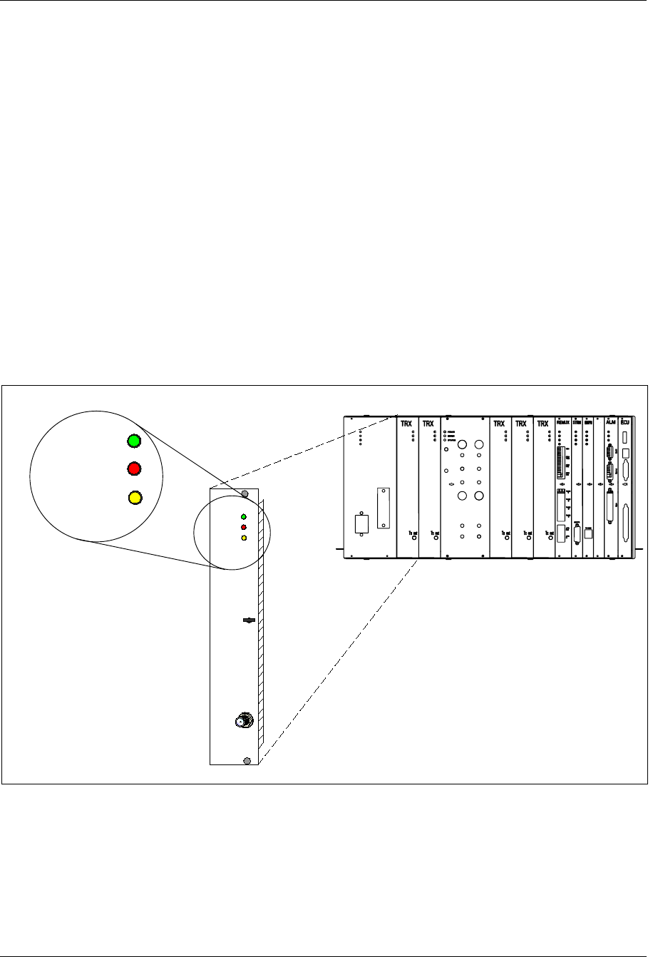
Installation
Recycle Packing Material
4. Recycle the packing materials in accordance with the local
regulations.
16 LED Indications
Active devices are equipped with Light Emitting Diodes (LEDs) to
indicate the status of the device.
In general:
•Green LEDs indicate the power is on.
•Red LEDs indicate an error has occurred (a red LED that is on,
indicates that an unspecified error has occurred in that unit).
•Yellow LEDs show operational status.
✚
Tx out
POWER
ERROR
STATUS
✚
TRX
1900
POWER
ERROR
STATUS
Figure 4-40. LED on a TRX
1/1551-EN/LZB 119 3312 Uae Rev PA4 1998-10-05 4-59

Installation
16.1 PSU LEDs
In the RBS 884 Micro (1900 MHz) PSU unit, four LED indicators are
provided for the following:
•PSU
•AC Mains
•DC Output
•Current Limit
Note: During battery charging, the Current Limit LED will be on.
This is a normal indication.
16.2 TRX LEDs
In the RBS 884 Micro (1900 MHz) TRX units, three LED indicators are
provided for the following:
•Red Error LED
– ON: Indicates an error or fault with the TRX
– FLASH 3 Hz: Power-up test
– FLASH: Communication with EMRPM is lost
•Yellow Status LED
– OFF: No PCM signal present on the primary interface
– FLASHING: Indicates TRX(s) are on (33% duty cycle =1
timeslot, 66% duty cycle=2 timeslot, 99% duty cycle=3 timeslot).
•Green Power LED
– ON: Indicates the TRX is powered on
–
4-60 1/1551-EN/LZB 119 3312 Uae Rev PA4 1998-10-05

Installation
16.3 REMUX LEDs
In the RBS 884 Micro 1900 REMUX unit, four LED indicators are
provided for the following:
•Red Error LED
– ON: Indicates an error or fault with the TRX
– FLASH 3 Hz: Power-up test
– FLASH: Communication with EMRPM/S is lost
•Yellow Status LEDs
– OFF: No PCM signal present on the primary interface
– FLASH 3 Hz: Primary PCM interface is not operable
– FLASH 15 Hz:Primary PCM interface is operable
•Green Power LED
– ON: Indicates the REMUX is powered on
–
16.4 ANP (RFTL) LEDs
In the RBS 884 Micro (1900 MHz) ANP (RFTL) unit, three LED
indicators are provided for the following:
•Red Error LED
– ON: Indicates an error or fault with the ANP (RFTL)
–
•Yellow Status LED
– OFF: No PCM signal present on the primary interface
–
•Green Power LED
– ON: Indicates the ANP (RFTL) is powered
–
1/1551-EN/LZB 119 3312 Uae Rev PA4 1998-10-05 4-61

Installation
16.5 STRM LEDs
In the RBS 884 Micro (1900 MHz) STRM unit, two LED indicators are
provided for the following:
•Yellow Status LED
– FLASHING 8 Hz: Blocked
– FLASHING 1 Hz: Deblocked
– FLASHING Two blinks-pause-two blinks: STC communication
not working
•Green Power LED
– ON: Indicates the STRM is powered on
–
16.6 ALM LEDs
In the RBS 884 Micro (1900 MHz) ALM unit, three LED indicators are
provided for the following:
•Red Error LED
– ON: Indicates an error or fault with the TRX
– FLASH 3 Hz: Power-up test
– FLASH: Communication with EMRPM/S is lost
•Yellow Status LED
– OFF: No PCM signal present on the primary interface
–
•Green Power LED
– ON: Indicates the TRX is powered on
4-62 1/1551-EN/LZB 119 3312 Uae Rev PA4 1998-10-05

Installation
16.7 EMRPM LEDs
In the RBS 884 Micro (1900 MHz) EMRPM unit, four LED indicators are
provided for the following:
•Red Error LED
– ON: Indicates an error or fault with the EMRPM
–
•Yellow Status 1 LED
– OFF: Turned off by APZ at EMRPM reset
– ON: Turned on when EMRPM is started
– FLASHING: Starts to blink when traffic is pending and is set to
ON when there is no traffic
•Yellow Status 2 LED
– OFF: Turned off by APZ at EMRPM reset Turned off at restart
and when all devices are blocked
– ON: Turned on when at least one device is deblocked but all
individuals are blocked
– FLASHING: When there are at least one deblocked individual
•Green Power LED
– ON: Indicates the EMRPM is powered on
16.8 ECU LEDs
The ECU in the RBS 884 Micro (1900 MHz) provides interfaces to the
following cabinet equipment:
•Main DC Power Bus Disconnect Relay
•Temperature Sensors
•PSU
•Main Heater
•ALM
Two seven-segment displays on the front of the ECU provide error codes
to indicate equipment failure alarms and ALM status (see Table 4-12 on
page 4-63).
Table 4-12. ECU Error Codes
Error Code Description
A0 Temperature shutdown alarm
A1 Single fan alarm
A2 Multiple fan alarm
1/1551-EN/LZB 119 3312 Uae Rev PA4 1998-10-05 4-63

Installation
Table 4-12. ECU Error Codes (Continued)
A3 Main heater alarm
A4 PSU failure alarm
A5 Battery temperature alarm
F1 Fan #1 failure
F2 Fan #2 failure
F3 Fan #3 failure
F4 Fan #4 failure
FF Fan test
S1 Ambient temperature Sensor failure
S2 Inlet temperature Sensor failure
S3 Subrack Temperature Sensor failure
S4 Exhaust Temperature Sensor failure
S5 Battery Compartment Temperature Sensor failure
S6 Inlet 2 (backup) Temperature Sensor failure
C0 Cold start
C1 Cold start timeout > 30 minutes
17 Site Expansion
A RBS 884 Micro (1900 MHz) can be expanded by adding the following:
•TRXs to one or more of the cabinets (Section 17.1 on page 4-65).
•One or two Primary Cabinets (Section 17.2 on page 4-69).
After completing the site expansion, fill in the Site Inventory list in the Site
Installation Documentation: note the date and the R-state of the new units.
This section also provides additional cabling information for the following
configurations:
•One-sector sites, one cabinet with two antennas
•One-sector sites, one cabinet with four antennas
•Two-sector sites, two cabinets with two antennas per cabinet
•Two-sector sites, two cabinets with four antennas per cabinet
•Three-sector sites, three cabinets with two antennas per cabinet
•Three-sector sites, three cabinets with four antennas per cabinet
4-64 1/1551-EN/LZB 119 3312 Uae Rev PA4 1998-10-05
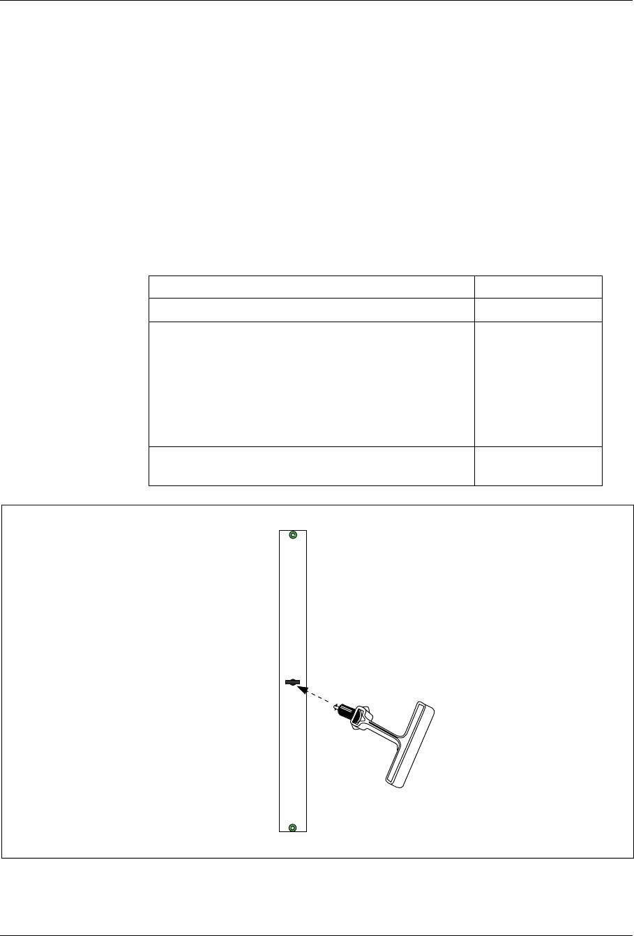
Installation
17.1 Adding TRX Boards
Replacing the base station’s RMUs with TRXs increases the call handling
capacity in that particular sector.
Note: Other options for single sector site expansion are not supported
by the RBS 884 Micro (1900 MHz).
17.1.1 Tools
The tools required for adding TRXs to a cabinet are shown in Table 4-13
on page 4-65, Figure 4-41 on page 4-65, Figure 4-42 on page 4-66, and
Figure 4-43 on page 4-66.
Table 4-13. Tools for Adding TRXs
Description Product Number
ESD Wrist Strap and Cable LYB 250 01/14
Torque Wrench set including:
- Torque Wrench for torque 0.6 Nm
(to use with the SMA tool and the torx bit TX10
- Torx bit TX10
(for circuit board screws)
- SMA tool
(for the coaxial cables)
LTT 601 82
Unit Extractor Tool (Handle and Button) LTD 117 02 and
LTD 117 14
RMU
Figure 4-41. Unit Extractor Tool (extracting an RMU)
1/1551-EN/LZB 119 3312 Uae Rev PA4 1998-10-05 4-65
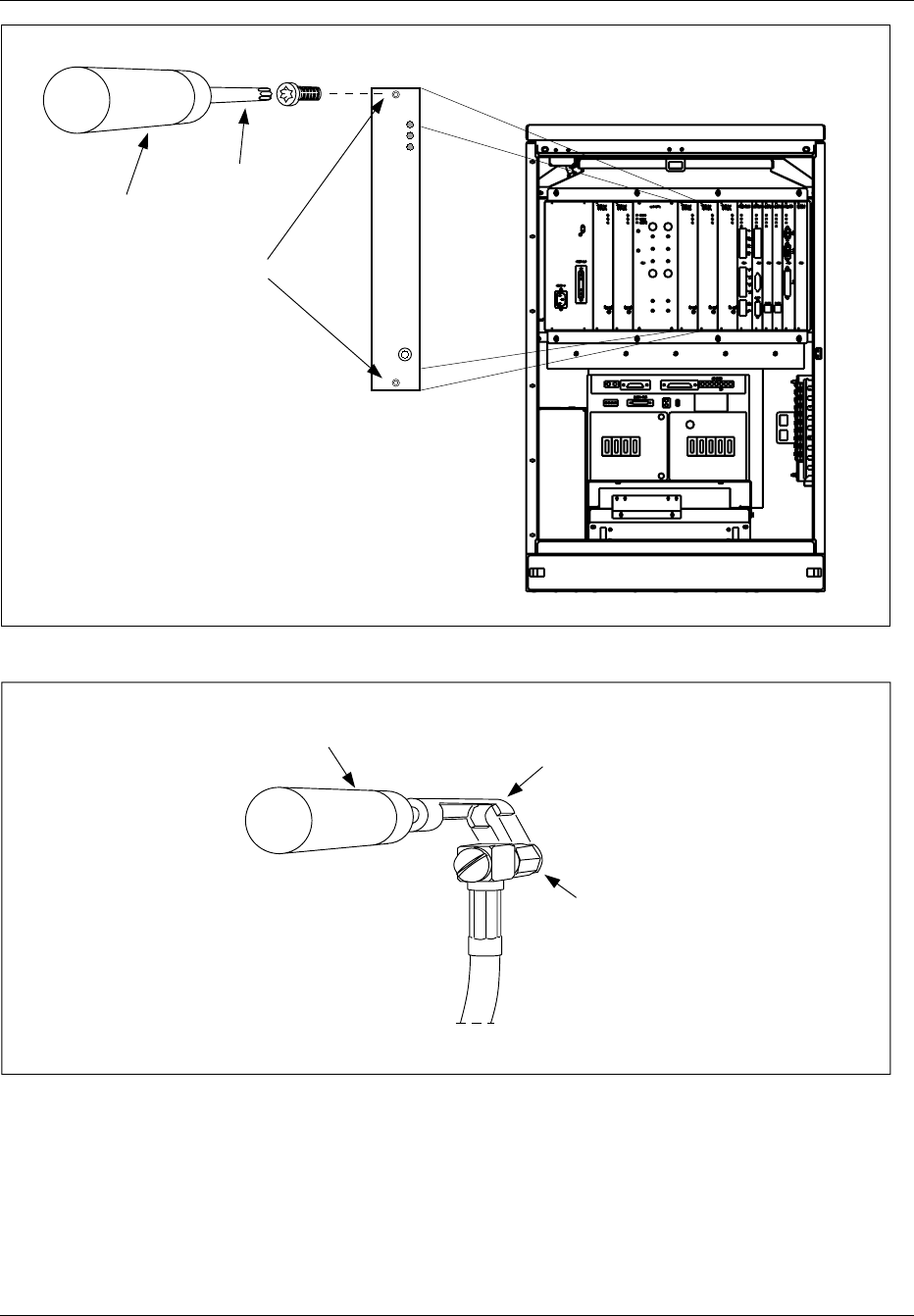
Installation
Torx Bit T10
Torque Wrench
Unit Screws
Power
Error
Status
Tx out
TRX
Figure 4-42. Torque Wrench with Torx TX10
Torque Wrench SMA Tool
SMA Connector
Figure 4-43. Torque Wrench with SMA Tool
4-66 1/1551-EN/LZB 119 3312 Uae Rev PA4 1998-10-05
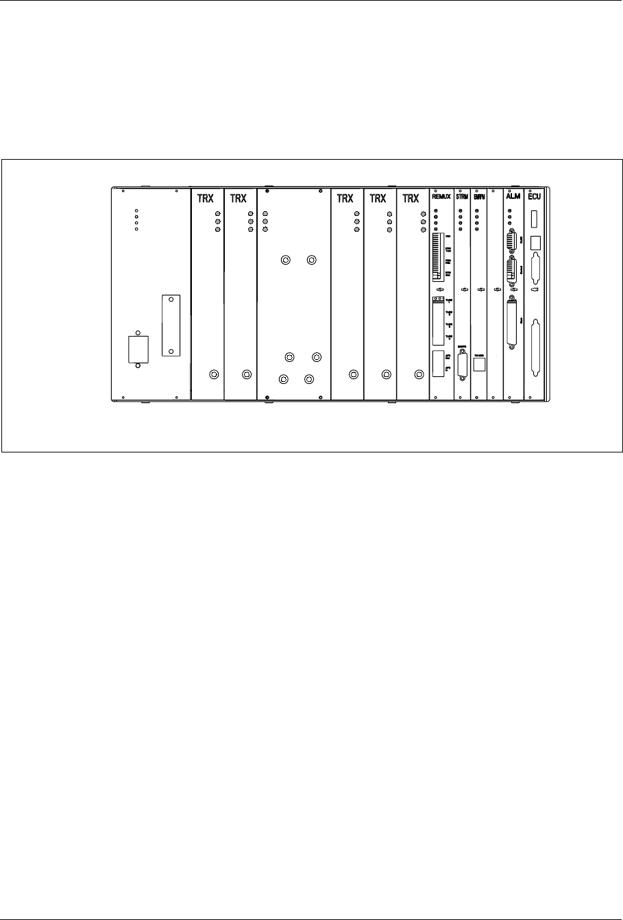
Installation
17.1.2 TRX Positions
Refer to Figure 4-44 on page 4-67 for TRX positions. TRXs are added to
the cabinet in the following positions.
•3rd TRX in slot 4
•4th TRX in slot 5
12 3 54786 9 11 12 13
ANP/RFTL
Power
Error
Status
DPX
ANT 1 DPX
ANT 2
TX IN 1
TX IN 2
TX IN 3
TX IN 4
Power
Error
Status
Power
Error
Status
Power
Error
Status
Power
Error
Status
Power
Error
Status
Tx out Tx out Tx out Tx out Tx out
Figure 4-44. Unit Positions
17.1.3 Installation Procedure
1. Attach the ESD strap to your wrist and connect the free end of the
strap cable to an appropriate ground conductor in the cabinet.
In Section 3 on page 4-5 there is more information about ESD.
2. Remove the first RMU (dummy TRX).
Use the torque wrench with the Torx bit TX10 to loosen the
screws, and the unit extractor tool to pull the blank panel out.
3. Carefully slide the TRX into the cabinet following the guides. Push
the it firmly into the backplane connector.
4. Use the torque wrench with the Torx bit TX10 to tighten the
screws on the front.
Turn the torque wrench until it slides to tighten screws to 0.6 Nm.
5. Check that the green power LED on the unit is on and the red error
LED is off. If this is not the case, refer to the troubleshooting
procedure in the Maintenance part for detection of units suspected
to be faulty.
1/1551-EN/LZB 119 3312 Uae Rev PA4 1998-10-05 4-67

Installation
6. The cables are installed as shown in Figure 4-45 on page 4-69.
Choose the appropriate figure (depending on the number of
antennas connected to the cabinet).
When attaching the cable connector to the connector on the unit,
hand-tighten as much as possible. Thereafter, fully tighten using
the torque wrench with the SMA tool.
Turn the torque wrench until it slides to tighten connector to 0.6
Nm.
7. Follow the same procedure for all other TRXs to be installed.
8. Report to the MSC.
4-68 1/1551-EN/LZB 119 3312 Uae Rev PA4 1998-10-05
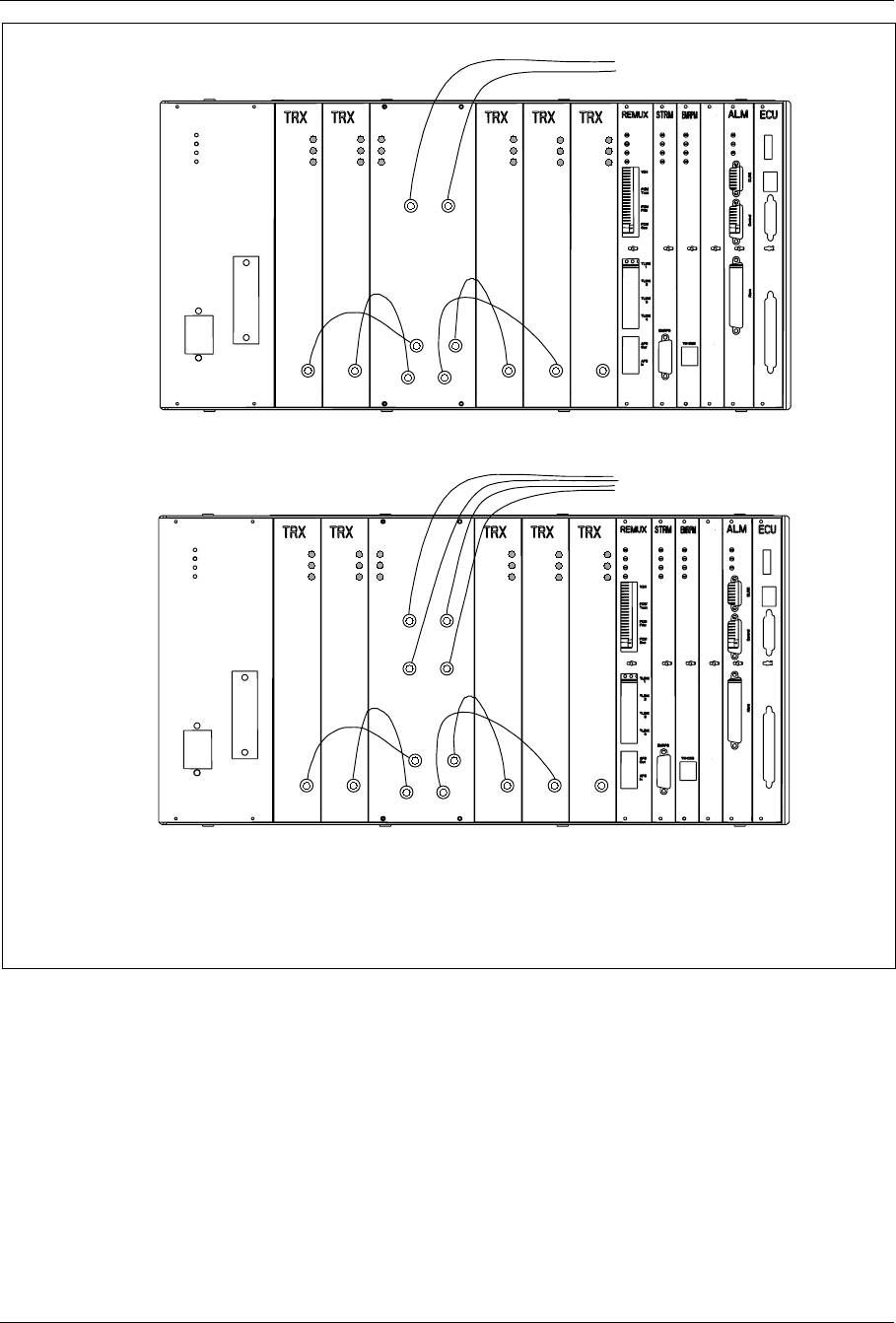
Installation
Note: The TRX board in position 6 is used for DVER
Cabinets illustrated are Main Cabinets, but the cabling is the same for Primary Cabinets.
Cabinet using Two Antennas
Cabinet using Four Antennas
ANP/RFTL
Power
Error
Status
DPX
ANT 1 DPX
ANT 2
TX IN 1
TX IN 2
TX IN 3
TX IN 4
Power
Error
Status
Power
Error
Status
Power
Error
Status
Power
Error
Status
Power
Error
Status
Tx out Tx out Tx out Tx out Tx out
To antenna terminals
on I/O connector plate
Pos. 6
ANP/RFTL
Power
Error
Status
Power
Error
Status
Power
Error
Status
Power
Error
Status
Power
Error
Status
Tx out Tx out Tx out Tx out Tx out
Power
Error
Status
DPX
ANT 1 DPX
ANT 2
TX IN 1
TX IN 2
TX IN 3
TX IN 4
DPX
ANT 3 DPX
ANT 4
To antenna terminals
on I/O connector plate
Pos. 6
Figure 4-45. TRX Cable Connections for Cabinets with Antennas
17.2 Adding Cabinets
A radio base station is expanded to a two-sector site by adding a Primary
cabinet to the Main cabinet. The radio base station is expanded to a three-
sector site by adding an additional Primary cabinet. Two or three cabinets
that occupy the same site location and serve separate sectors are referred to
1/1551-EN/LZB 119 3312 Uae Rev PA4 1998-10-05 4-69

Installation
as collocated cabinets. Collocated cabinets are connected together with the
following cables:
•EMRPM Bus (EMRPB). The EMRPB cables are daisy chained from
the Main cabinet to the Primary 1 cabinet and then to the Primary 2
cabinet.
•TLINKS. Two TLINKS are run directly from the Main cabinet to
each of the Primary cabinets.
•Air Frame Synchronization (AFS). The AFS cable is daisy chained
from the Main cabinet to the Primary 1 cabinet and then to the
Primary 2 cabinet.
These cables are run in liquid tight flexible conduit from the floor of one
cabinet to the floor of the next cabinet. The Main and Primary cabinets
have two 1 3/8 inch (33 mm) diameter knock-outs for 1 inch (25 mm)
diameter conduit. Both cabinet cable entries are located on the bottom
surface of the cabinet in the front right corner.
Note: All cables routed into and through the pedestal mounting base
should be encased in liquid tight flexible conduit. Do not
terminate the liquid tight flexible conduit at the pedestal base
knock-outs.
A diagram of cable routing for collocated cabinets is shown in Figure 4-46
on page 4-71.
4-70 1/1551-EN/LZB 119 3312 Uae Rev PA4 1998-10-05
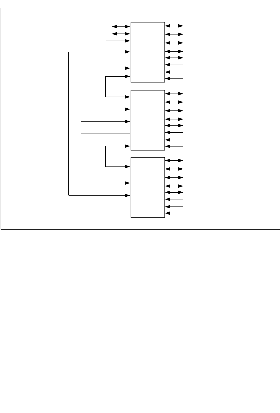
Installation
MAIN
CABINET
PRIMARY
CABINET 1
PRIMARY
CABINET 2
RX/TX Antenna
RX/TX Antenna
TX Antenna
TX Antenna
TW/BSTI
Alarms
AC Power
External Battery
RX/TX Antenna
RX/TX Antenna
TX Antenna
TX Antenna
TW/BSTI
Alarms
AC Power
External Battery
RX/TX Antenna
RX/TX Antenna
TX Antenna
TX Antenna
TW/BSTI
Alarms
AC Power
External Battery
PCM to/from MSC
PCM to/from other site
A
F
S
A
F
S
E
M
R
P
B
E
M
R
P
B
T
L
I
N
K
T
L
I
N
K
AFS
Figure 4-46. Cable Routing for Collocated Cabinets
Use the Extension Cable Set (NTM 201 1807) for each collocated cabinet.
The Extension Cable Set is customer assembled. The cable set contains
the following:
•Cable (six meters)
•Two Insulation Displacement Connection (IDC) connectors
•Two IDC connector backshells
•Connector tool (for seating wires)
•
The EMRPB cable transfers control data between the STRM in the Main
cabinet and the CONN in the Primary cabinet. Refer to Table 4-14 on
page 4-72 for cable connector assembly:
1/1551-EN/LZB 119 3312 Uae Rev PA4 1998-10-05 4-71

Installation
Table 4-14. Extension Cable Connector Signals and Pin Connections
Connector A
(Pin No.) Signal Connector B
(Pin No.)
1CLKM+ (Transmit clock from STRM) 1
2 DATAM+ (Transmit data from STRM) 2
3
DATAM+ (Transmit data from
STRM)BLO+ (Blocking Signal from
STRM)
3
4BSB+ (Bus standby signal from STRM) 4
5CLKS+ (Receive clock to STRM) 5
6 DATAS+ (Receive Data to STRM) 6
7Not Connected 7
8GND 8
9 CLKM- (Transmit clock from STRM) 9
10 DATAM- (Transmit data from STRM) 10
11 DATAM- (Transmit data from STRM) 11
12 BSB- (Bus standby signal from STRM) 12
13 CLKS- (Receive clock to STRM) 13
14 DATAS- (Receive Data to STRM) 14
15 Not Connected 15
NOTE: To ensure adequate shielding, clamp the cable braid and shield between
backshell halves during assembly.
17.3 One-Sector Sites
Before you begin the installation, attach the ESD strap to your wrist and
connect the free end of the strap cable to an appropriate ground conductor
in the cabinet.
The configurations with one cabinet have internal cables only. Figure 4-47
on page 4-73 and Figure 4-48 on page 4-73 are shown here only as
information to the reader. The cabinets are shown as fully configured.
4-72 1/1551-EN/LZB 119 3312 Uae Rev PA4 1998-10-05
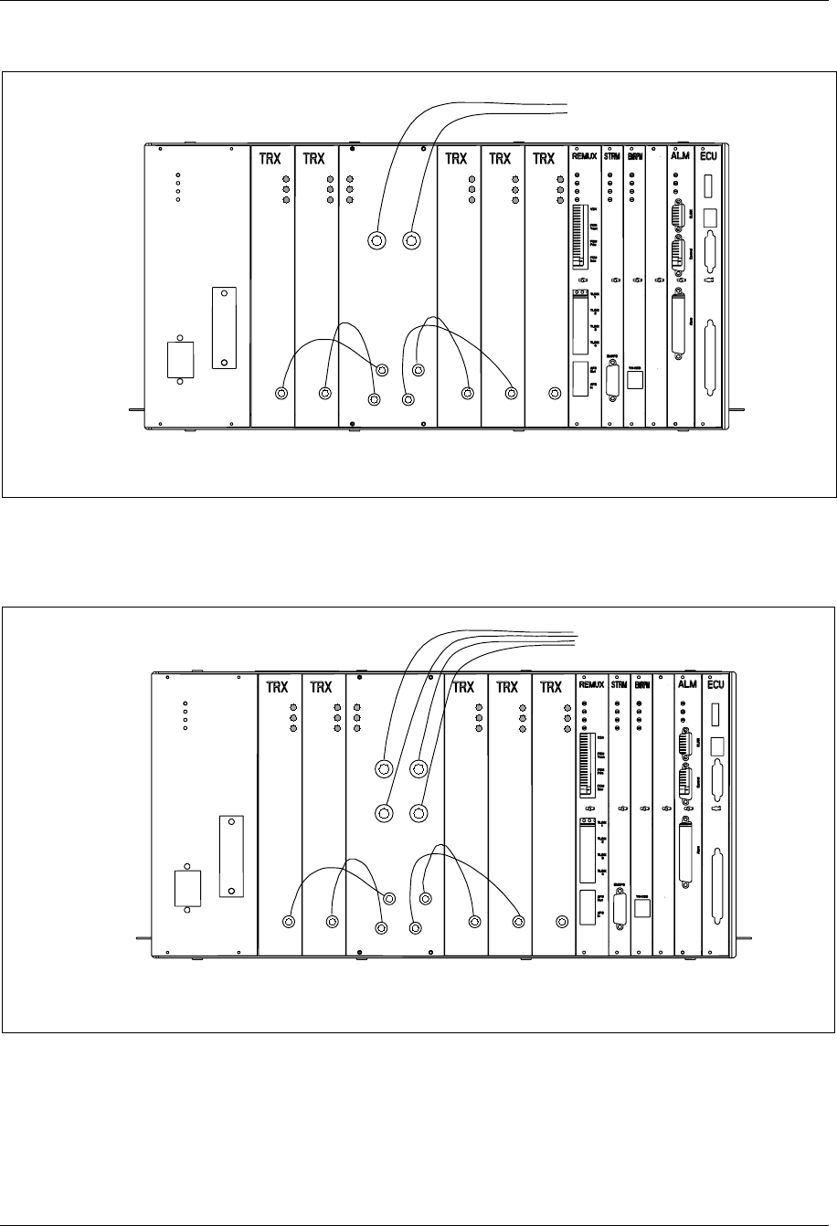
Installation
17.3.1 One-Sector Sites, One Cabinet, Two Antennas
Power
Error
Status
RX/TX
ANT 1 RX/TX
ANT 2
TX IN 1
TX IN 2
TX IN 3
TX IN 4
Power
Error
Status
Power
Error
Status
Power
Error
Status
Power
Error
Status
Power
Error
Status
Tx out Tx out Tx out Tx out Tx out
To antenna terminals
on I/O connector plate
Note: The TRX board in position 6 is used for DVER
Pos. 6
Figure 4-47. One-Sector Site, One Cabinet, Two Antennas
17.3.2 One-Sector Sites, One Cabinet, Four Antennas
Note: The TRX board in position 6 is used for DVER
Power
Error
Status
Power
Error
Status
Power
Error
Status
Power
Error
Status
Power
Error
Status
Tx out Tx out Tx out Tx out Tx out
Power
Error
Status
TX IN 1
TX IN 2
TX IN 3
TX IN 4
RX/TX
ANT 1 RX/TX
ANT 2
RX/TX
ANT 3 RX/TX
ANT 4
Pos. 6
To antenna terminals
on I/O connector plate
Figure 4-48. One-Sector Site, One Cabinet, Four Antennas
1/1551-EN/LZB 119 3312 Uae Rev PA4 1998-10-05 4-73
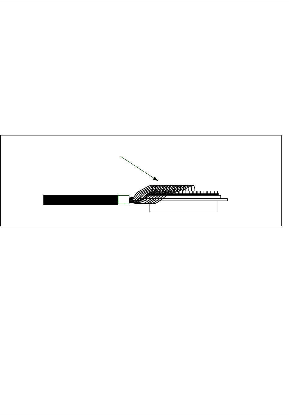
Installation
17.4 Two-Sector Sites
Before you begin the installation, attach the ESD strap to your wrist and
connect the free end of the strap cable to an appropriate ground conductor
in the cabinet.
Note: Cables are routed between cabinets using 1” liquid-tight
flexible conduit. Conduit is run from the floor of the Main
cabinet to the floor of the Primary cabinet.
Note: Prior to installing the external EMRP bus (EMRPB) cable,
remove the backshell from the cable connector. Fold the
connector inline with the cable. See Figure 4-49 on page 4-74.
Wrap the connector with tape and pull through the conduit.
After the cable is pulled into position, remove the tape and
reassemble backshell.
Wrap with tape to protect connector and wires.
Figure 4-49. Cable Connector with Backshell Removed
17.4.1 Two-Sector Site, Two Cabinets, Two Antennas
Use the following steps to cable the Main and Primary cabinets in a two-
sector site using two antennas. Use the cables in the Extension Cable Set
(NTM 201 1807). See Figure 4-50 on page 4-75 for placement of cables.
1. Connect a cable from the AFS OUT connector on the REMUX
board in the Main cabinet to the External AFS IN connector on the
CONN board in the Primary cabinet.
2. Connect a cable from the TLINK 1 Interface connector on the
REMUX board in the Main cabinet to the TLINK 1 Interface
connector on the CONN board in the Primary cabinet.
3. Connect a cable from the EMRPB Interface connector on the
STRM board in the Main cabinet to the top EMRPB connector on
the CONN board in the Primary cabinet.
4. Insert a termination plug (RVN991200012) in the bottom EMRPB
Interface connector on the CONN board.
4-74 1/1551-EN/LZB 119 3312 Uae Rev PA4 1998-10-05
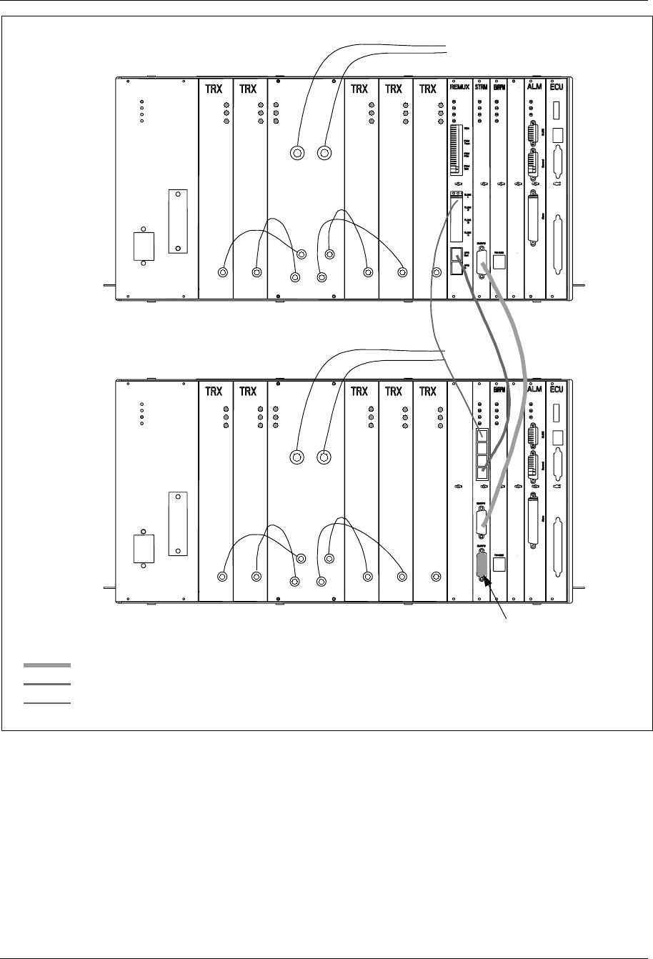
Installation
Note: The TRX board in position 6 is used for DVER
Power
Error
Status
RX/TX
ANT 1 RX/TX
ANT 2
TX IN 1
TX IN 2
TX IN 3
TX IN 4
Power
Error
Status
Power
Error
Status
Power
Error
Status
Power
Error
Status
Power
Error
Status
Tx out Tx out Tx out Tx out Tx out
To antenna terminals
on I/O connector plate
ANP/RFTL
Power
Error
Status
RX/TX
ANT 1 RX/TX
ANT 2
TX IN 1
TX IN 2
TX IN 3
TX IN 4
Power
Error
Status
Power
Error
Status
Power
Error
Status
Power
Error
Status
Power
Error
Status
Tx out Tx out Tx out Tx out Tx out
Pos. 6
Pos. 6
Terminator
Main
Cabinet
Primary
Cabinet
EMRPB
AFS
TLINK
Figure 4-50. Two-Sector Site, Two Cabinets, Two Antennas
1/1551-EN/LZB 119 3312 Uae Rev PA4 1998-10-05 4-75

Installation
17.4.2 Two-Sector Site, Two Cabinets, Four Antennas
Use the following steps to cable the Main and Primary cabinets in a two-
sector site using four antennas. Use the cables in the Extension Cable Set
(NTM 201 1807). See Figure 4-51 on page 4-77 for placement of cables.
1. Connect a cable from the TLINK 1 Interface connector on the
REMUX board in the Main cabinet to the TLINK 1 Interface
connector on the CONN board in the Primary cabinet.
2. Connect a cable from the External AFS OUT connector on the
REMUX board in the Main cabinet to the External AFS IN
connector on the CONN board in the Primary cabinet.
3. Connect a cable from the EMRPB Interface connector on the
STRM board in the Main cabinet to the top EMRPB connector on
the CONN board in the Primary cabinet.
4. Insert a termination plug (RVN991200012) in the bottom EMRPB
Interface connector on the CONN board.
4-76 1/1551-EN/LZB 119 3312 Uae Rev PA4 1998-10-05
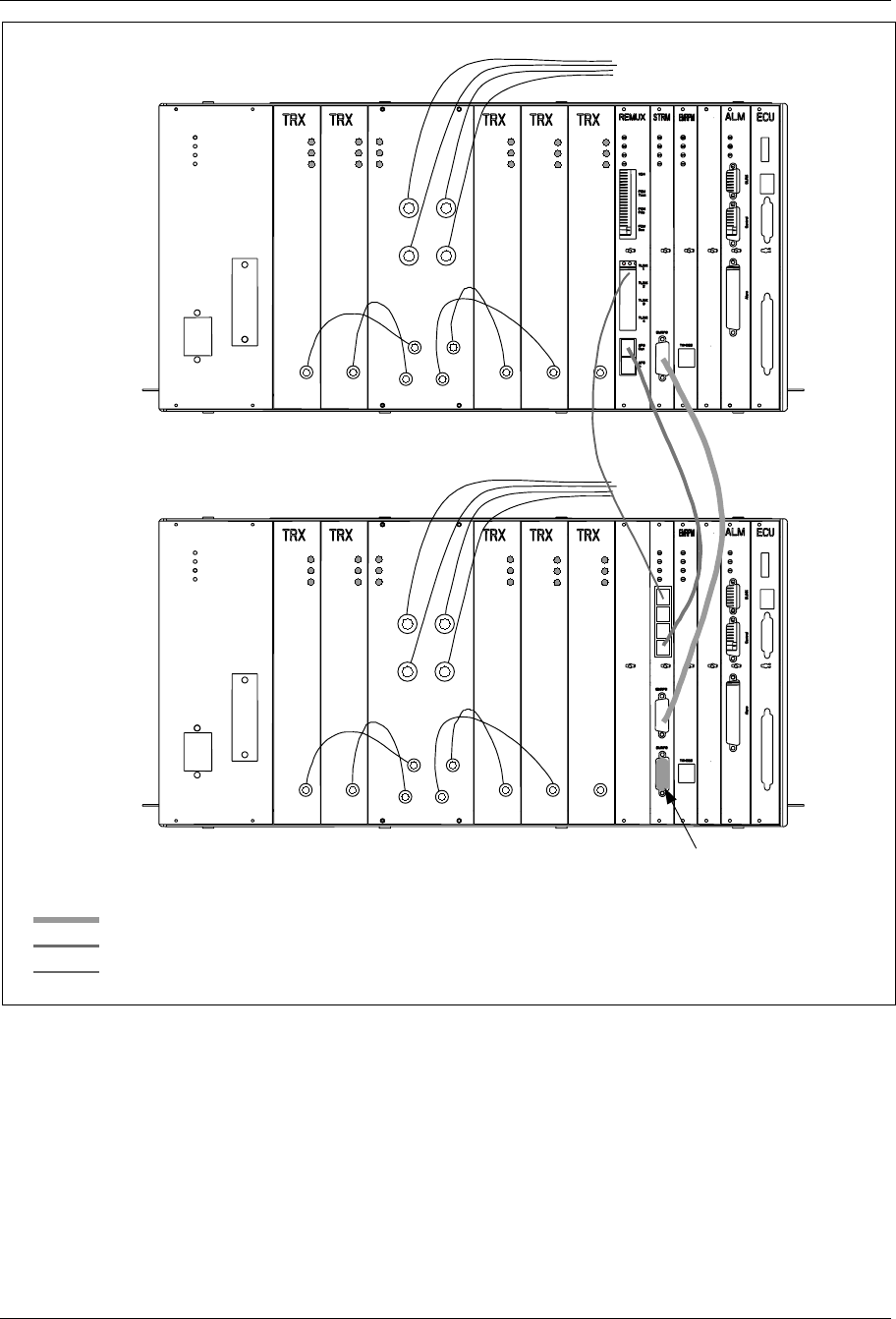
Installation
Note: The TRX board in position 6 is used for DVER
Power
Error
Status
Power
Error
Status
Power
Error
Status
Power
Error
Status
Power
Error
Status
Tx out Tx out Tx out Tx out Tx out
Power
Error
Status
TX IN 1
TX IN 2
TX IN 3
TX IN 4
RX/TX
ANT 1 RX/TX
ANT 2
RX/TX
ANT 3 RX/TX
ANT 4
To antenna terminals
on I/O connector plate
Pos. 6
Power
Error
Status
Tx out
Power
Error
Status
Power
Error
Status
Power
Error
Status
Power
Error
Status
Tx out Tx out Tx out Tx out
Power
Error
Status
TX IN 1
TX IN 2
TX IN 3
TX IN 4
Pos. 6
Terminator
EMRPB
AFS
TLINK
Main
Cabinet
Primary
Cabinet
RX/TX
ANT 1 RX/TX
ANT 2
RX/TX
ANT 3 RX/TX
ANT 4
Figure 4-51. Two-Sector Site, Two Cabinets, Four Antennas
17.5 Three Sector Sites
Before you begin the installation, attach the ESD strap to your wrist and
connect the free end of the strap cable to an appropriate ground conductor
in the cabinet.
1/1551-EN/LZB 119 3312 Uae Rev PA4 1998-10-05 4-77
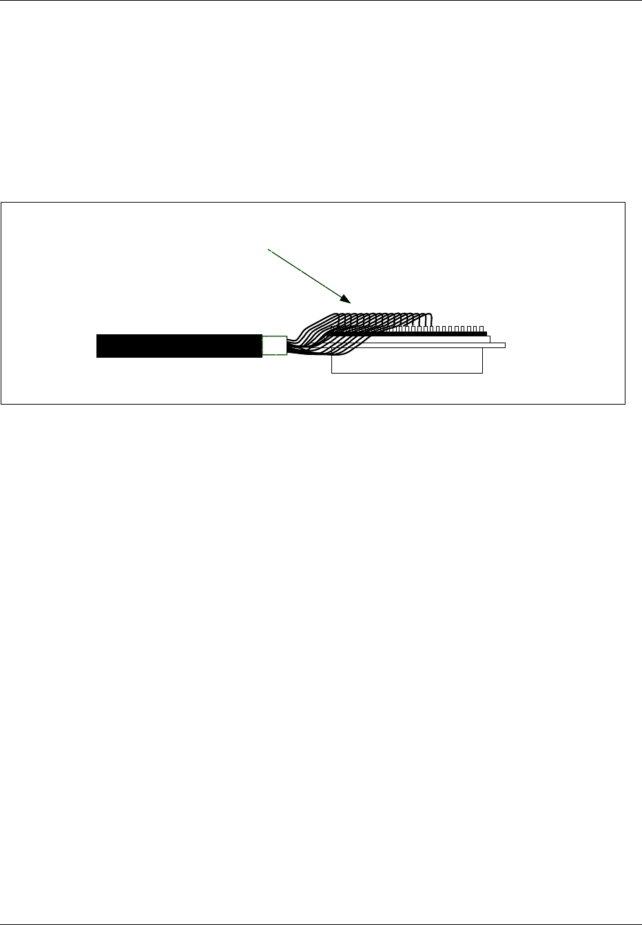
Installation
Note: Cables are routed between cabinets using 1” liquid-tight
flexible conduit. Conduit is run from the floor of the Main
cabinet to the floor of the Primary cabinets.
Note: Prior to installing the external EMRPMB cable, remove the
backshell from the cable connector. Fold the connector inline
with the cable. See Figure 4-49 on page 4-741. Wrap the
connector with tape and pull through the conduit. After the
cable is pulled into position, remove the tape and reassemble
backshell.
Wrap with tape to protect connector and wires.
Figure 4-52. Cable Connector with Backshell Removed
17.5.1 Three-Sector Site, each Cabinet has Two Antennas
Use the following steps to cable the Main, Primary 1, and Primary 2
cabinets in a three-sector site using two antennas. Use the cables in the
Extension Cable Set (NTM 201 1807). See Figure 4-53 on page 4-80 for
placement of cables.
1. Connect a cable from the TLINK 1 Interface connector on the
REMUX board in the Main cabinet to the TLINK 1 Interface
connector on the CONN board in the Primary 1 cabinet.
2. Connect a cable from the TLINK 2 Interface connector on the
REMUX board in the Main cabinet to the TLINK 1 Interface
connector on the CONN board in the Primary 2 cabinet.
3. Connect a cable from the External AFS OUT connector on the
REMUX board in the Main cabinet to the External AFS IN
connector on the CONN board in the Primary 1 cabinet.
4. Connect a cable from the External AFS OUT connector on the
CONN board in the Primary 1 cabinet to the External AFS IN
connector on the CONN board in the Primary 2 cabinet.
5. Connect a cable from the EMRPB Interface connector on the
STRM board in the Main cabinet to the top EMRPB connector on
the CONN board in the Primary 1 cabinet.
4-78 1/1551-EN/LZB 119 3312 Uae Rev PA4 1998-10-05

Installation
6. Connect a cable from the bottom EMRPB Interface connector on
the CONN board in the Primary 1 cabinet to the top EMRPB
connector on the CONN board in the Primary 2 cabinet.
7. Insert a termination plug (RVN991200012) in the bottom EMRPB
Interface connector on the CONN board in the Primary 2 cabinet.
1/1551-EN/LZB 119 3312 Uae Rev PA4 1998-10-05 4-79
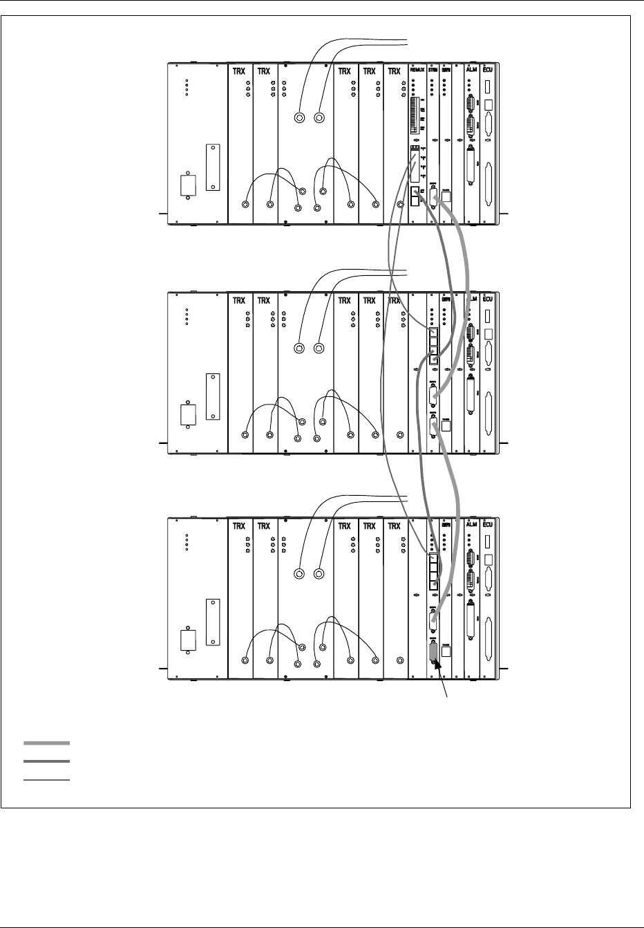
Installation
Note: The TRX board in position 6 is used for DVER
Main
Cabinet
Primary 1
Cabinet
Primary 2
Cabinet
Power
Error
Status
RX/TX
ANT 1 RX/TX
ANT 2
TX IN 1
TX IN 2
TX IN 3
TX IN 4
Power
Error
Status
Power
Error
Status
Power
Error
Status
Power
Error
Status
Power
Error
Status
Tx out Tx out Tx out Tx out Tx out
To antenna terminals
on I/O connector plate
Power
Error
Status
RX/TX
ANT 1 RX/TX
ANT 2
TX IN 1
TX IN 2
TX IN 3
TX IN 4
Power
Error
Status
Power
Error
Status
Power
Error
Status
Power
Error
Status
Power
Error
Status
Tx out Tx out Tx out Tx out Tx out
Power
Error
Status
RX/TX
ANT 1 RX/TX
ANT 2
TX IN 1
TX IN 2
TX IN 3
TX IN 4
Power
Error
Status
Power
Error
Status
Power
Error
Status
Power
Error
Status
Power
Error
Status
Tx out Tx out Tx out Tx out Tx out
Pos. 6
Pos. 6
Pos. 6
Terminator
EMRPB
AFS
TLINK
Figure 4-53. Three-Sector Site, each Cabinet has Two Antennas
4-80 1/1551-EN/LZB 119 3312 Uae Rev PA4 1998-10-05

Installation
17.5.2 Three-Sector Site, each Cabinet has Four Antennas
Use the following steps to cable the Main, Primary 1, and Primary 2
cabinets in a three-sector site using four antennas. Use the cables in the
Extension Cable Set (NTM 201 1807). See Figure 4-54 on page 4-82 for
placement of cables.
1. Connect a cable from the TLINK 1 Interface connector on the
REMUX board in the Main cabinet to the TLINK 1 Interface
connector on the CONN board in the Primary 1 cabinet.
2. Connect a cable from the TLINK 2 Interface connector on the
REMUX board in the Main cabinet to the TLINK 1 Interface
connector on the CONN board in the Primary 2 cabinet.
3. Connect a cable from the External AFS OUT connector on the
REMUX board in the Main cabinet to the External AFS IN
connector on the CONN board in the Primary 1 cabinet.
4. Connect a cable from the External AFS OUT connector on the
CONN board in the Primary 1 cabinet to the External AFS IN
connector on the CONN board in the Primary 2 cabinet.
5. Connect a cable from the EMRPB Interface connector on the
STRM board in the Main cabinet to the top EMRPB connector on
the CONN board in the Primary 1 cabinet.
6. Connect a cable from the bottom EMRPB Interface connector on
the CONN board in the Primary 1 cabinet to the top EMRPB
connector on the CONN board in the Primary 2 cabinet.
7. Insert a termination plug (RVN991200012) in the bottom EMRPB
Interface connector on the CONN board in the Primary 2 cabinet.
1/1551-EN/LZB 119 3312 Uae Rev PA4 1998-10-05 4-81
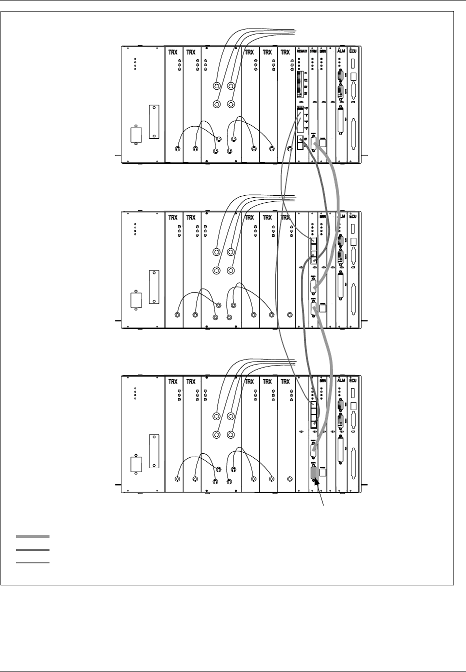
Installation
Note: The TRX board in position 6 is used for DVER
Main Cabinet
Primary 1
Cabinet
Primary 2
Cabinet
EMRPB
AFS
TLINK
Power
Error
Status
Power
Error
Status
Power
Error
Status
Power
Error
Status
Power
Error
Status
Tx out Tx out Tx out Tx out Tx out
Power
Error
Status
TX IN 1
TX IN 2
TX IN 3
TX IN 4
RX/TX
ANT 1 RX/TX
ANT 2
RX/TX
ANT 3 RX/TX
ANT 4
To antenna terminals
on I/O connector plate
Power
Error
Status
Tx out
Power
Error
Status
Power
Error
Status
Power
Error
Status
Power
Error
Status
Tx out Tx out Tx out Tx out
Power
Error
Status
RX/TX
ANT 1 RX/TX
ANT 2
TX IN 1
TX IN 2
TX IN 3
TX IN 4
RX/TX
ANT 3 RX/TX
ANT 4
Power
Error
Status
Tx out
Power
Error
Status
Power
Error
Status
Power
Error
Status
Power
Error
Status
Tx out Tx out Tx out Tx out
Power
Error
Status
RX/TX
ANT 1 RX/TX
ANT 2
TX IN 1
TX IN 2
TX IN 3
TX IN 4
RX/TX
ANT 3 RX/TX
ANT 4
Pos. 6
Pos. 6
Pos. 6
Terminator
Figure 4-54. Three-Sector Site, each Cabinet has Four Antennas
4-82 1/1551-EN/LZB 119 3312 Uae Rev PA4 1998-10-05
Installation
18 RBS 884 Micro (1900 MHz) Cabinet Repainting
This section provides instructions for repainting RBS 884 Micro (1900
MHz) cabinets. The instructions are intended as general recommendations
only and may not be suitable in all applications.
18.1 Required Materials and Tools
18.1.1 Materials
Prior to repainting the cabinet, obtain all materials listed in Table 4-15 on
page 4-83
Table 4-15. Cabinet Repainting Materials
Part Number Description
Refer to Paint
Manufacturer
Two-component polyurethane coating (paint chip
required for color matching)
N/A 80 grit (or finer) Sandpaper (for orbital sander)
N/A 120 grit (or finer) Sandpaper (for finish sanding)
N/A Tack Cloth
N/A Masking Tape
18.1.2 Tools
Prior to repainting the cabinet, obtain all tools listed in Table 4-16 on page
4-83
Table 4-16. Cabinet Repainting Tools
Part Number Description
N/A Orbital Sander
N/A Paint Spraying Equipment
N/A Sanding Blocks (as required)
18.2 Cabinet Surface Preparation
Prior to repainting the RBS 884 Micro (1900 MHz) cabinet, prepare the
cabinet surface as outlined in the following steps:
1/1551-EN/LZB 119 3312 Uae Rev PA4 1998-10-05 4-83

Installation
DANGER!
Paint, paint dust, and paint refinishing chemicals can be hazardous to your
health and result in injury or damage to equipment. Do not breathe paint
fumes or paint dust. Wear protective breathing equipment and work only
in well ventilated areas. Follow all local safety practices.
Caution!
Sanding the surface of the RBS 884 Micro (1900 MHz) cabinet may result
in reduced corrosion resistance. Also, use of a darker paint color will
degrade the thermal performance of the cabinet.
1. Using an orbital sander with 80 grit or finer sandpaper, lightly sand
all surfaces to be painted.
2. Blow off any excess sanding dust with compressed air.
3. Using a tack cloth, wipe down all surfaces.
4. If scratches or imperfections are visible in the surface, lightly sand
surfaces again using 120 grit or finer sandpaper.
5.
Caution!
To ensure proper paint adhesion, all paint dust and any other looses
material must be removed from the cabinet surface.
Using a tack cloth, wipe down all surfaces.
6. Mask all areas that are not to be painted, including hinges and door
hardware.
18.3 Cabinet Painting
To apply the primer and finish paint to the cabinet, perform the following
steps:
Applying Primer Paint to Cabinet
1. Using appropriate paint spraying equipment, apply primer to all areas
to be painted.
4-84 1/1551-EN/LZB 119 3312 Uae Rev PA4 1998-10-05

Installation
2. Allow primer to dry for a minimum of 30 minutes.
Note: Paint drying times vary according to environmental
conditions such as temperature and humidity. Refer
to the paint manufacturer’s specifications for drying
times.
3. When primer is dry, feather sand the edges of the primed areas.
4. Wipe all surfaces clean with a tack cloth. Ensure surface is free of
all dust and debris.
Applying Finish Paint to Cabinet
5. Prepare finish paint as specified by the paint manufacturer.
Note: The finish paint is a two-part polyurethane coating
(paint and catalyst) that hardens with age. Painting
time is limited after mixing. Refer to the paint
manufacturer’s specifications for working life of the
mixed paint.
6. Using appropriate paint spraying equipment, apply the finish paint to
all areas to be painted.
7. Allow paint to dry and apply one or more additional coats.
8. Allow painted cabinet to dry for a minimum of 24 hours (48 hours
recommended) before handling or removing any masking.
9. After 24 to 48 hours, carefully remove masking from hinges and
door hardware.
Note: Two-component polyurethane paint includes a
catalyst that causes the paint to harden and become
more durable with age. Within the first 48 hours
after application, the paint is soft and scuffs easily.
Use care to not scuff or mar the surface.
1/1551-EN/LZB 119 3312 Uae Rev PA4 1998-10-05 4-85

Installation
4-86 1/1551-EN/LZB 119 3312 Uae Rev PA4 1998-10-05

Part 5
Hardware Replacement
1 Introduction . ................. 5-3
2 Safety Considerations . ............ 5-3
2.1 Grounding of the RBS Cabinets . . .... 5-3
2.2 Voltage Hazards . ............ 5-4
2.3 Radio Frequency Radiation ........ 5-4
2.4 Beryllium Oxide . ............ 5-4
2.5 Heavy Loads . . . ............ 5-5
3 Product Handling and Inspection ........ 5-6
4 General Troubleshooting ............ 5-6
4.1 Prerequisites and Tools . . ........ 5-6
4.2 Troubleshooting Procedure for RBS Cabinets 5-7
5 Alarm Troubleshooting . ............ 5-11
6 RBS Unit Hardware Replacement ........ 5-14
6.1 Prerequisites and Tools . . ........ 5-15
6.2 Power Supply Unit (PSU) Replacement . . 5-18
6.3 REMUX Unit Replacement ........ 5-20
6.4 STRM Unit Replacement . ........ 5-23
6.5 CONN Unit Replacement . ........ 5-25
6.6 EMRPM Unit Replacement ........ 5-28
6.7 TRX Unit Replacement . . ........ 5-30
6.8 ANP/RFTL Unit Replacement . . . .... 5-33
6.9 Alarm (ALM) Unit Replacement . . .... 5-35
6.10 Environmental Control Unit (ECU)
Replacement . . . ............ 5-38
6.11 Fan Replacement ............ 5-40
6.12 Main Heater Replacement ........ 5-42
6.13 Battery Heater Replacement . . . .... 5-45
6.14 Battery Replacement . . . ........ 5-49
6.15 AC Surge Suppressor Replacement .... 5-52
6.16 T1(E1) PCM Primary Surge Suppressor
Replacement . . . ............ 5-55
6.17 T1(E1) PCM Secondary Surge Suppressor
Replacement . . . ............ 5-56
6.18 Air Filter Replacement . . ........ 5-58
2/1551-EN/LZB 119 3312 Uae Rev PA4 1998-10-05 5-1

Hardware Replacement
5-2 2/1551-EN/LZB 119 3312 Uae Rev PA4 1998-10-05

Hardware Replacement
1 Introduction
This part of the manual lists procedures for basic troubleshooting and
hardware replacement of faulty items of equipment, such as cabinet units
or cables.
The use of the procedures by a site maintenance technician may depend on
instructions from MSC personnel able to determine the status of the RBS
site equipment from the MSC.
The site maintenance technician may be asked to replace a particular unit
using the procedure in Section 6 on page 5-14, or to follow the
troubleshooting procedure in Section 4 on page 5-6 for determining a
faulty unit. The troubleshooting procedure is also used if failures occur
during the power-up procedure.
2 Safety Considerations
2.1 Grounding of the RBS Cabinets
This product is Safety Class 1 equipment.
The RBS cabinets must be connected to the AC power through a grounded
power cable, with the ground wire firmly connected to an electrical ground
(safety ground) at the power outlet.
2/1551-EN/LZB 119 3312 Uae Rev PA4 1998-10-05 5-3

Hardware Replacement
DANGER!
Any interruption of the protective (grounding) conductor, or disconnection
of the protective ground terminal will cause a potential shock hazard that
could result in personal injury.
2.2 Voltage Hazards
DANGER!
Voltage over 100V is used in the AC equipment at the site. Observe safety
precautions. Contact with power can cause death. Do not be misled by the
term “low voltage”. Under adverse conditions, potentials as low as 50V
can result in death. Do not work alone while working with AC power.
DANGER!
Do not touch high voltage connections when installing or operating
equipment. If necessary, disconnect the AC power cable from the power
unit. Do not connect the AC power cable to the power unit when the unit
is removed from the RBS cabinet.
The power cable serves as the only power disconnection device for the
cabinet.
Keep one hand away from the equipment, if the nature of the maintenance
permits, to reduce the possibility of current flowing through vital body
organs.
2.3 Radio Frequency Radiation
DANGER!
Radio frequency radiation from an antenna may be a danger to health,
causing severe burns to skin and clothing.
All transmitters must be disabled prior to working with or near antenna.
2.4 Beryllium Oxide
Some equipment contains beryllium oxide in ceramic form.
5-4 2/1551-EN/LZB 119 3312 Uae Rev PA4 1998-10-05

Hardware Replacement
Warning!
Beryllium oxide is poisonous and constitutes a health hazard if present in
finely dispersed form, such as dust or smoke, which can be inhaled. Read
local hazardous chemical regulations before working with beryllium oxide.
Units with components containing beryllium oxide are marked with a
warning label. For detailed information on properties, health and
environmental hazards, refer to the regulations issued by the local
authorities.
The following rules must be obeyed by all persons handling beryllium
oxide:
•Ceramics containing beryllium oxide must not be scraped, filed,
ground, treated with acid or machined in any other way.
•Compressed air must not be used to clean units containing beryllium
oxide.
•You must always wear protective gloves when handling beryllium
oxide.
•Use wet rags to collect dust and particles from damaged beryllium
oxide components. After use, place the rags in plastic bags and seal
the bags completely.
Scrapped beryllium oxide must be treated as environmentally hazardous
waste. Local authorities enforce regulations, regarding the treatment and
disposal of environmentally hazardous waste. Investigate the local
regulations which are applicable to you and comply with them.
2.5 Heavy Loads
Warning!
A heavy load lifted incorrectly can cause injury to persons and damage to
the equipment can result.
A heavy load is considered to be 10 kg (approximately 22 lbs).
Note: A fully equipped RBS 884 Micro (1900 MHz) cabinet exceeds
105 kg (230 lbs). Therefore Ericsson recommends that two
persons are present during the installation.
2/1551-EN/LZB 119 3312 Uae Rev PA4 1998-10-05 5-5

Hardware Replacement
3 Product Handling and Inspection
Components may be damaged because of ESD. Read the Electrostatic
Discharge section for information and directions.
A hardware replacement unit must always be kept in its original box until
it is installed on a site.
The unit must not be exposed to wide variations in temperature, to direct
sunshine, or to high levels of humidity, such as may occur if the unit is
left in a car.
When handling circuits boards, do not touch any components or connector
pins.
If the packing material is damaged, inspect the unit immediately. If the
unit appears to be damaged, follow your local procedures or return it to
your local service center for repair or hardware replacement.
A faulty unit must always be accompanied by a completed Repair Traveler
Note, with written information concerning the circumstances of the
suspected fault. A Repair Traveler Note is a tie-on tag, which can be
attached to the unit.
4 General Troubleshooting
Operational status of the RBS equipment is indicated by LEDs mounted on
the front of the units plugged into the cabinets.
In general, green LEDs are used for power status, red LEDs are used for
error status, and yellow LEDs are used to indicate other types of
operational status.
The procedure in this section is used to determine faulty units by visual
inspection of the LEDs and other means. If the procedure does not result
in the detection of a faulty unit, the MSC must be informed in order to
determine if a problem at the site is still indicated at the MSC.
4.1 Prerequisites and Tools
4.1.1 Prerequisites
The troubleshooting procedure in this section is intended to be followed if
an RBS unit fault is detected during the power-up procedure, or at the
request of the MSC as a result of an RBS site equipment error indication
at the MSC.
5-6 2/1551-EN/LZB 119 3312 Uae Rev PA4 1998-10-05
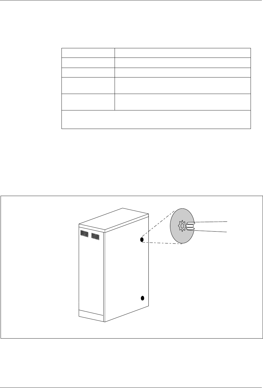
Hardware Replacement
4.1.2 Tools
All the tools needed to troubleshoot the RBS 884 Micro (1900 MHz) are
shown in Table 5-1 on page 5-7.
Table 5-1. Tools List
Product Number Description
Pen
LYB 250 01/14 ESD Wrist Strap and Cable2
LTD 117 02 and
LTD 117 14
Unit Extractor Tool (Handle + Button)
AC or AC/DC Voltmeter1
(for checking the line voltage)
1Included in Tool Kit LTT 601 044/1
2Included in Tool Case LTT 601 84
4.2 Troubleshooting Procedure for RBS Cabinets
RBS Cabinet Access
1. Unlock the door latches as shown in Figure 5-1 on page 5-7
Figure 5-1. Unlocking the RBS Cabinet Door
2/1551-EN/LZB 119 3312 Uae Rev PA4 1998-10-05 5-7
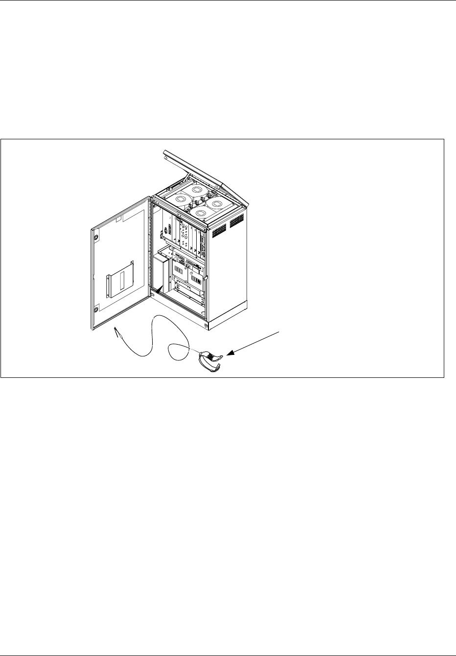
Hardware Replacement
2. Open the cabinet door and secure the wind latch at the top of the
door. Open the door until the shoulder slides into the slot at the end
of the bar.
Note: To release the wind latch, lift up on the bar and
close the door.
3. Attach the ESD strap to your wrist and connect the “alligator”
connector to a suitable ground on the cabinet chassis. Do not attach
to a painted or coated surface. See Figure 5-2 on page 5-8.
ESD Wrist Strap
Note: Attach alligator clip to suitable
ground (unpainted surface) in cabinet.
Figure 5-2. Opening the RBS Cabinet and Attaching the ESD Strap
Troubleshooting Flowchart
4. Follow the flowchart shown in Figure 5-3 on page 5-9 or Figure 5-4
on page 5-10 to identify a unit suspected to be faulty.
5-8 2/1551-EN/LZB 119 3312 Uae Rev PA4 1998-10-05
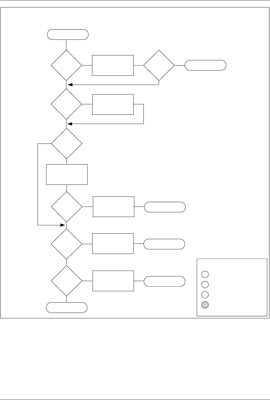
Hardware Replacement
AC Power Troubleshooting
PSU OK
AC OK
DC OUTPUT ON
PSU CURRENT LIMIT
PSU LEDs
PSU OK
LED
on?
PSU
DC
OUTPUT ON
LED
on?
PSU
AC OK
LED
on?
No
Yes
AC
MAIN
breaker
on?
Turn AC MAIN
Breaker on.
No
Yes
No
Reset PSU circuit
breaker
and check
AC power cable.
PSU
AC OK
LED
on?
No
Replace PSU.
Refer to
Power Unit (PSU)
Replacement Section.
Report to MSC
Replace PSU.
Refer to
Power Unit (PSU)
Replacement Section.
Report to MSC
Yes
Yes
Refer to DC Power
Troubleshooting
Start
Yes
No
AC
CONNECTED
indicator
on?
Verify incoming
AC power
is OK
Yes
No
AC
CONNECTED
indicator
on?
Report to MSC
Replace PSU.
Refer to
Power Unit (PSU)
Replacement Section.
Report to MSC
No
Yes
Figure 5-3. Troubleshooting Flowchart for AC Power Connection
2/1551-EN/LZB 119 3312 Uae Rev PA4 1998-10-05 5-9
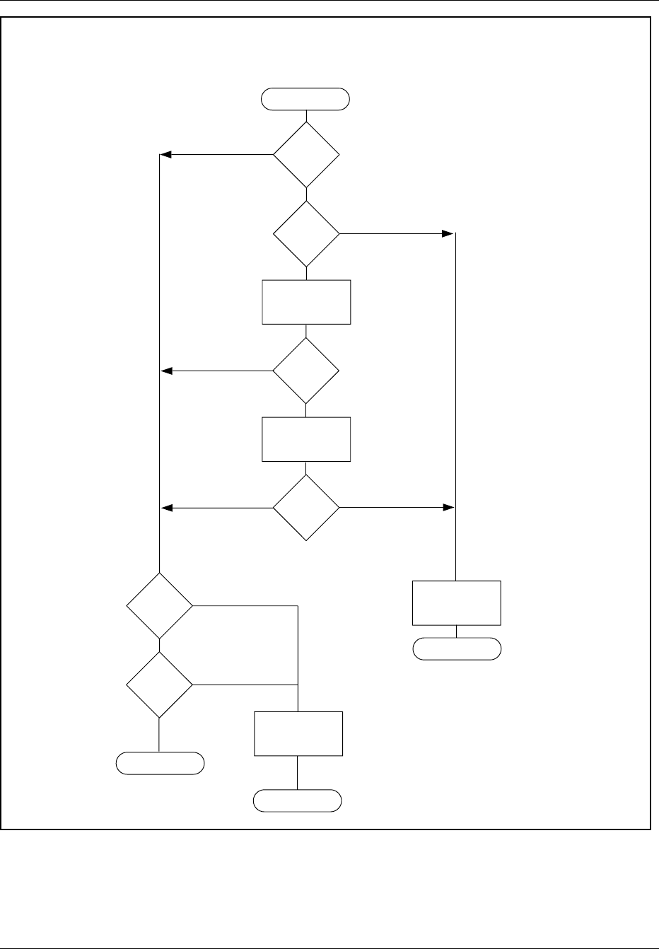
Hardware Replacement
Start
Fan
airflow
OK?
No
Replace Fan.
Refer to the
Fan Replacement
section.
Report to MSC
Reset Fan breaker
and check fan power
cable
Ensure DC
power available
from power cable
Fan
airflow
OK?
Yes
Fan
Failure Code
on
ECU?
No
Fan
airflow
OK?
Yes
Error Codes
on
ECU?
Replace suspect unit.
Refer to the
Unit Replacement
Section.
All unit
red LEDs
off?
Report to MSC
Yes No
No
No
Yes
Yes
No
DC Power Troubleshooting
Report to MSC
Yes
Figure 5-4. Troubleshooting Flowchart for DC Power Connection
5-10 2/1551-EN/LZB 119 3312 Uae Rev PA4 1998-10-05

Hardware Replacement
5. Troubleshooting procedures has been carried out as part of the
power-up procedure, return to the appropriate section and complete
the power-up procedure.
5 Alarm Troubleshooting
Refer to Table 5-2 on page 5-11 for RBS 884 Micro (1900 MHz) alarm
conditions and corrective actions. For alarm routing, refer to both Table
5-2 on page 5-11 and Figure 5-5 on page 5-14.
Table 5-2.
Condition
Alarm Name Alarm Source/Routing Corrective Action/
Alarm Clearing
Fan not within ±25% of
set speed (checked once
per second)
Single Fan Alarm
From ECU/TRXs via
backplane
Reset Fan breaker
Two or more fans not
within ±25% of set speed
(checked once per
second)
Multi-Fan Alarm
From ECU/TRXs via
backplane
Reset Fan breaker
AC Mains ≤minimum
PSU voltage requirement
AC Mains Failure Alarm
From PSU via AC/DC
Distribution Box via cable
to ECU via cable to
EMRPM via backplane
Self clears when AC
Mains voltage is
adequate to power PSU
AC Mains > 100 VAC
and
DC Out < 24 VDC
and
Output Current < 1A.
PSU Failure Alarm
From PSU via AC/DC
Distribution Box via cable
to ECU via cable to
EMRPM via backplane
Self Clears (Trigger
conditions not valid) after
PSU power is within
specification
2/1551-EN/LZB 119 3312 Uae Rev PA4 1998-10-05 5-11
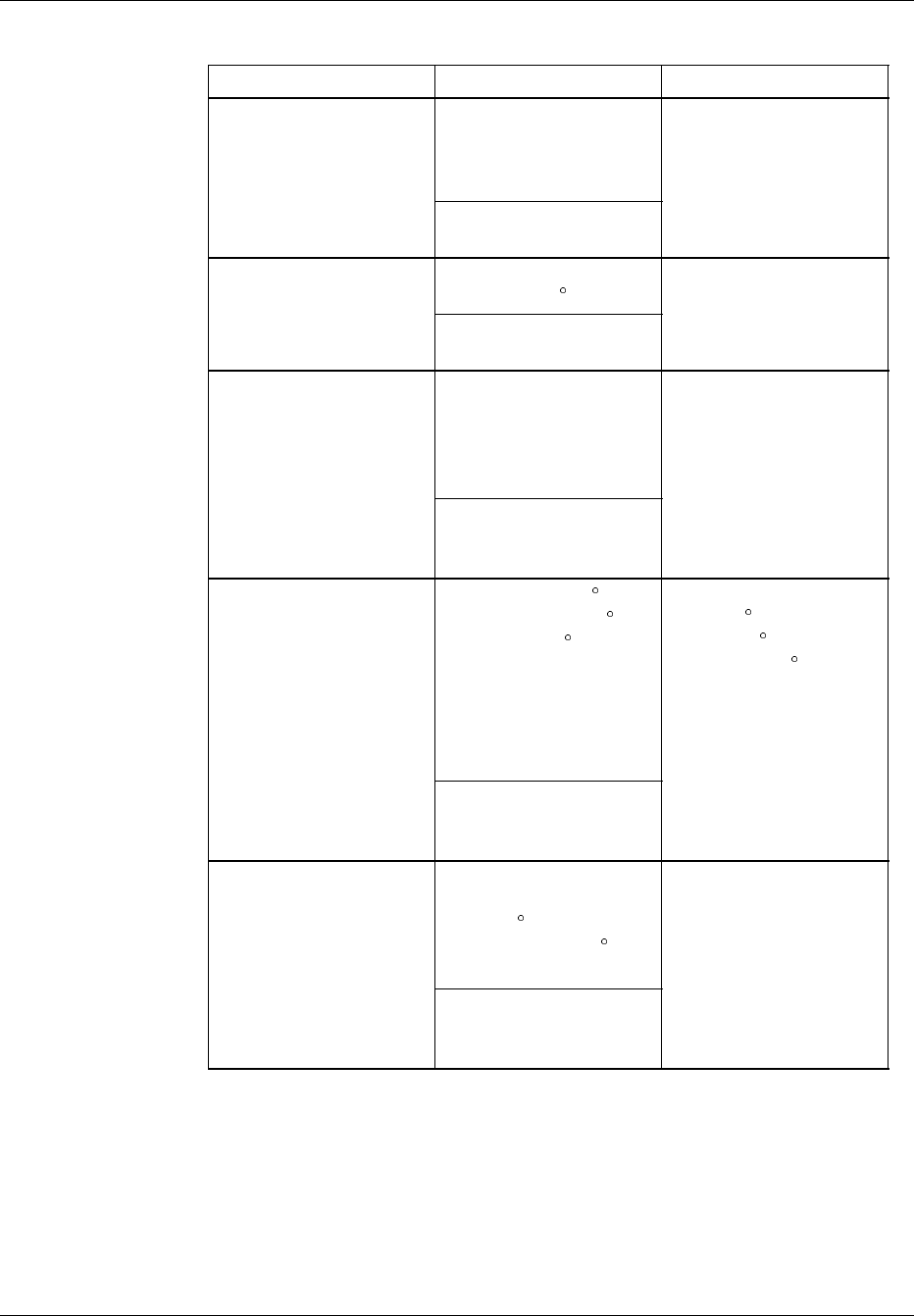
Hardware Replacement
Table 5-2. (Continued)
Condition
DCBus Voltage < 22.9
VDC. Disconnects
Battery when < 20.9
VDC.
Low Voltage Disconnect
Alarm
From AC/DC Distribution
Box to ALM via cable
Self Clears
Temperature of Battery
Terminal > 70
Battery Thermal Alarm
From AC/DC Distribution
Box to ALM via cable
Self clears
One or more
Temperature sensors
shorted or open
(checked once per
second)
Temperature Sensor
Failure Alarm
From ECU to AC/DC
Distribution Box via
cable to ALM via cable
Self clears
Subrack Inlet ≤-6 Cor
Subrack Inlet ≥+51 Cor
Exhaust ≥+62 C. After
alarm generation there is
a six second delay
before subrack is
disconnected (checked
once per second).
Temperature Shutdown
Alarm
From ECU to AC/DC
Distribution Box via
cable to ALM via cable
Self clears if Subrack
Inlet ≥-4 C and Subrack
Inlet ≤+49 C and
Exhaust ≤+60 C
Ten minute delay
(warning) if ambient
temp ≤0C and Subrack
Inlet < ambient + 5 C for
ten minutes.
Main Heater Failure
Alarm
From ECU to AC/DC
Distribution Box via
cable to ALM via cable
Reset Main Heater
breaker
5-12 2/1551-EN/LZB 119 3312 Uae Rev PA4 1998-10-05

Hardware Replacement
Table 5-2. (Continued)
Condition
Ambient temp > +15 C
and Battery
Compartment >
ambient + 10 C
or
Ambient temp < -5 C and
Battery Compartment <
ambient + 5 C
Battery Compartment
Temperature Alarm
From ECU to AC/DC
Distribution Box via
cable to ALM via cable
Self clears when
temperature returns to
within specifications.
AC Surge
No AC Power = alarm
AC Surge Suppressor
Alarm
From AC Surge
Suppressor via cable to
AC/DC Distribution Box
via cable to ALM
Self clears if AC Surge
Suppressor is not
damaged
Top or Front Door is
Open
Door Alarm
From Switches via cable
to AC/DC Distribution
Box via cable to ALM
Self clears when both
doors closed
2/1551-EN/LZB 119 3312 Uae Rev PA4 1998-10-05 5-13
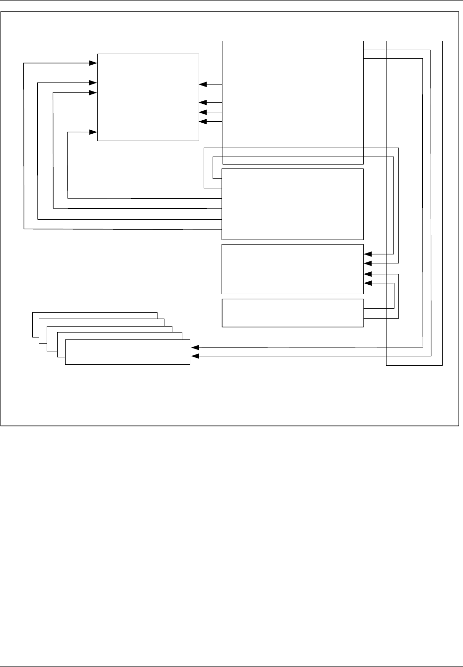
Hardware Replacement
External Alarm 0 (APT)
External Alarm 3 (APT)
External Alarm 4 (APT)
External Alarm 5 (APT)
External Alarm 6 (APT)
External Alarm 7 (APT)
External Alarm 8 (APT)
External Alarm 9 (APT)
Single Fan Alarm
Multiple Fan Alarm
Temperature Shutdown Alarm
Main Heater Alarm
Battery Comp. Temp. Alarm
Temp. Sensor Failure Alarm
AC Mains Failure Alarm
PSU Failure Alarm
Battery Thermal Discon. Alarm
Low Voltage Disconnect Alarm
Door Alarm
Surge Suppressor Alarm
MC-B Alarm
MC-A Alarm
ANP
AC Alarm (Alarm 3 - APT/Printou)
DC Alarm (Alarm 2 - APT/Printou)
MC-A Alarm (Alarm 1 - APT OBS)
MC-B Alarm (Alarm 0 - APT OBS)
EMRPM
ECU
ALM
Backplane
Distribution Box
Fan Alarm 1 (Malfunction Log)
Fan Alarm 2 (Malfunction Log)
Note: When both fan alarms
sent, APT alarm is generated.
Figure 5-5. RBS 884 Micro (1900 MHz) Alarm Routing
6 RBS Unit Hardware Replacement
When a suspected faulty unit is identified either by indications at the MSC
or by the troubleshooting procedure in Section 4 on page 5-6, follow the
appropriate procedure in this section to replace the unit.
Hardware replacement procedures are provided for the following devices:
•Power Supply Unit (PSU)
•REMUX Unit
•STRM Unit
5-14 2/1551-EN/LZB 119 3312 Uae Rev PA4 1998-10-05

Hardware Replacement
•CONN Unit
•EMRPM Unit
•TRX Unit
•ANP/RFTL Unit
•Alarm (ALM) Unit
•Environmental Control Unit (ECU)
•Fans
•Main Heater
•Battery Heater
•Batteries
•AC Surge Suppressor
•PCM (T1/E1) Primary Surge Suppressor
•PCM (T1/E1) Secondary Surge Suppressor
•Air Filter
6.1 Prerequisites and Tools
6.1.1 Prerequisites
Before a faulty unit is replaced, the hardware replacement unit must be
available and must have the same or higher R-state number (R-state letters
do not matter).
When units other than the power or fan unit are replaced, suitable blank
panels (8M, 10M, or 12M) or dummy TRXs (RMUs) must be available in
case the hardware replacement takes an extended amount of time. The
blank panels ensure proper cooling and EMC shielding.
6.1.2 Tools
The tools required for unit hardware replacement are shown in Table 5-3
on page 5-16, Figure 5-6 on page 5-16, Figure 5-7 on page 5-17 and
Figure 5-8 on page 5-17. Additionally, an ESD bag is required for the unit
suspected to be faulty (other type of bag can be used for fan and power
units).
2/1551-EN/LZB 119 3312 Uae Rev PA4 1998-10-05 5-15
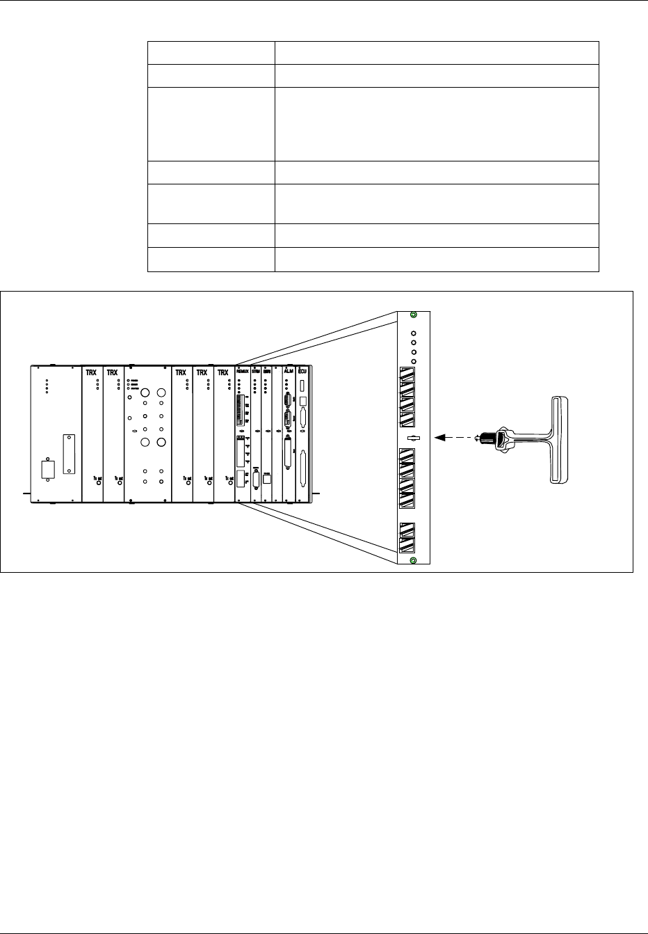
Hardware Replacement
Table 5-3. Tools for RBS Unit Hardware Replacement
Product Number Description
LYB 250 01/14 ESD Wrist Strap and Cable
LTT 601 82 Torque Wrench set including:
- Torque Wrench 0.6 Nm
- Torx bit T10 for circuit board screws
- SMA tool for the coaxial cables
LSA 126 11/10 Torx driver TX10
LTD 117 02 and
LTD 117 14
Unit Extractor Tool (Handle and Button)
Small Screwdriver or Pen (to set switches)
Repair Traveler Note
ANP/RFTL
PCM
Test
TLINK
1
TLINK
2
TLINK
3
TLINK
4
REMUX
Power
Error
V24
PCM
Prim
PCM
Sec
AFS
In
AFS
Out
Status 1
Status 2
NOTE: Before removing any unit, remove and save
the extractor hole plug. Replace plug after installing
or replacing unit.
Figure 5-6. Unit Extractor Tool (Example with the REMUX Unit)
5-16 2/1551-EN/LZB 119 3312 Uae Rev PA4 1998-10-05
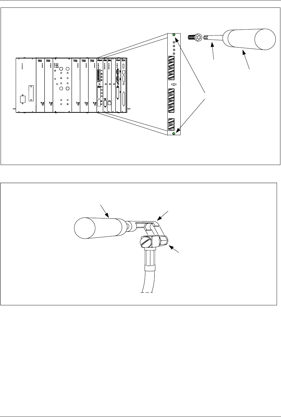
Hardware Replacement
Torx Bit T10
Torque Wrench
Unit Screws
ANP/RFTL PCM
Test
TLINK
1
TLINK
2
TLINK
3
TLINK
4
REMUX
Power
Error
V24
PCM
Prim
PCM
Sec
AFS
In
AFS
Out
Status 1
Status 2
Figure 5-7. Torque Wrench with Torx Bit TX10 (Example with the REMUX Unit)
Torque Wrench SMA Tool
SMA Connector
Figure 5-8. Torque Wrench with SMA Tool
2/1551-EN/LZB 119 3312 Uae Rev PA4 1998-10-05 5-17

Hardware Replacement
6.2 Power Supply Unit (PSU) Replacement
Unit Removal
Warning!
The following procedure will disable the RBS 884 Micro (1900
MHz). The unit will be out of service during the procedure. Contact
the MSC before performing the following procedure.
1. Get permission from the MSC to replace the unit. The MSC have to
block RBS units before you start.
2. Open the cabinet door as described in the steps beginning with Step
1 on page 5-7.
3.
Warning!
A unit must never be replaced with another with a lower R-state
number.
Ensure the hardware replacement unit is the same type as the unit to
be replaced, and that it has the same or higher R-state number.
4.
Warning!
Verify all TRX status LEDs (see Figure 5-14 on page 5-31) in the
cabinet are off. If the main cabinet power unit is to be changed, all
TRX status LEDs in all cabinets have to be checked.
If any TRX status LEDs are on or flashing, contact the MSC.
5. Attach the ESD strap to your wrist and connect the free end of the
strap cable to an appropriate ground conductor in the cabinet.
6. Locate the power unit shown in Figure 5-9 on page 5-19.
5-18 2/1551-EN/LZB 119 3312 Uae Rev PA4 1998-10-05
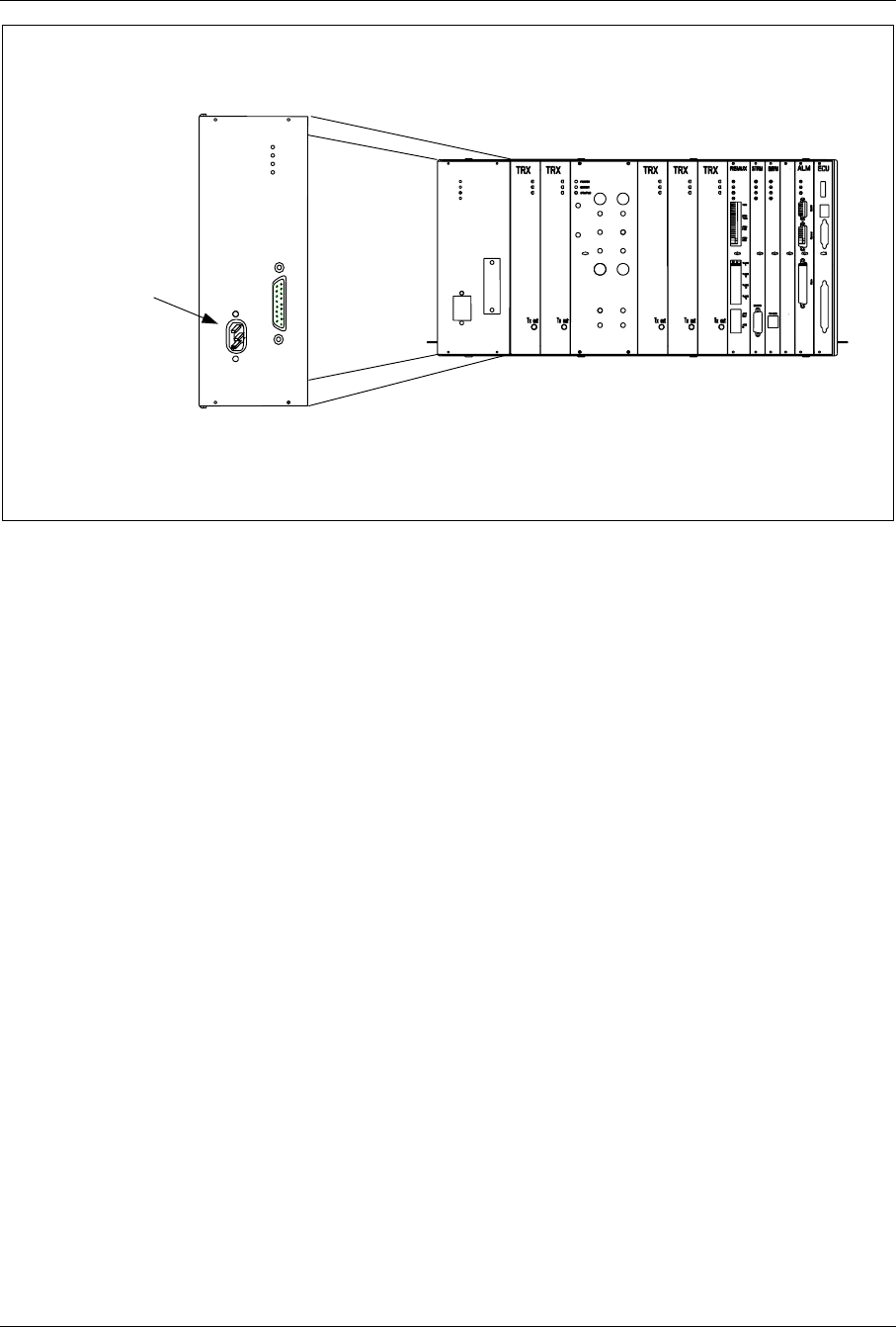
Hardware Replacement
ANP/RFTL
AC Power
Connector
Figure 5-9. The Power Unit
7. Power down the RBS cabinet by turning the PSU and AC Mains
circuit breakers off.
8. Disconnect the AC Power connector.
9. Disconnect the DC Power connector.
10. Use the torque wrench with the Torx bit TX10 to loosen the screws
on the front of the unit.
11. Pull the unit out, and place it in a bag.
Unit Hardware Replacement
12. Remove the hardware replacement unit from its packaging and
carefully slide the unit into the cabinet in place of the old unit.
13. Use torque wrench with the Torx bit TX10 to tighten the screws on
the front.
Turn the torque wrench until it slides to tighten to 0.6 Nm.
14. Reconnect the AC and DC Power connectors.
15. Follow the procedure for powering up the cabinet from the
Installation part Equipment Power Up.
16. Inform the MSC that the unit has been replaced, so that they can
perform a test.
2/1551-EN/LZB 119 3312 Uae Rev PA4 1998-10-05 5-19

Hardware Replacement
17. Remove the ESD strap cable from the cabinet, and detach it from
your wrist.
18. Close the cabinet door.
Unit Repair
19. Complete the Repair Traveler Note and attach it to the unit suspected
to be faulty.
20. Pack the unit in the packing material from the new unit and return it
to your local service center.
Plant Specification update
21. Update the Plant Specification in the Site Installation Documentation
concerning the new unit: use the comments field to note the date of
hardware replacement and new R-state number.
6.3 REMUX Unit Replacement
Unit Removal
Warning!
The following procedure will disable the RBS 884 Micro (1900
MHz). The unit will be out of service during the procedure. Contact
the MSC before performing the following procedure. This procedure
will also disable any additional sectors and cascaded RBS systems.
1. Get permission from the MSC to replace the unit.
2. Open the cabinet door as described in the steps beginning with Step
1 on page 5-7.
3.
Warning!
A unit must never be replaced with another with a lower R-state
number.
Check that the hardware replacement unit is the same type as the
unit to be replaced, and that it has the same or higher R-state.
5-20 2/1551-EN/LZB 119 3312 Uae Rev PA4 1998-10-05
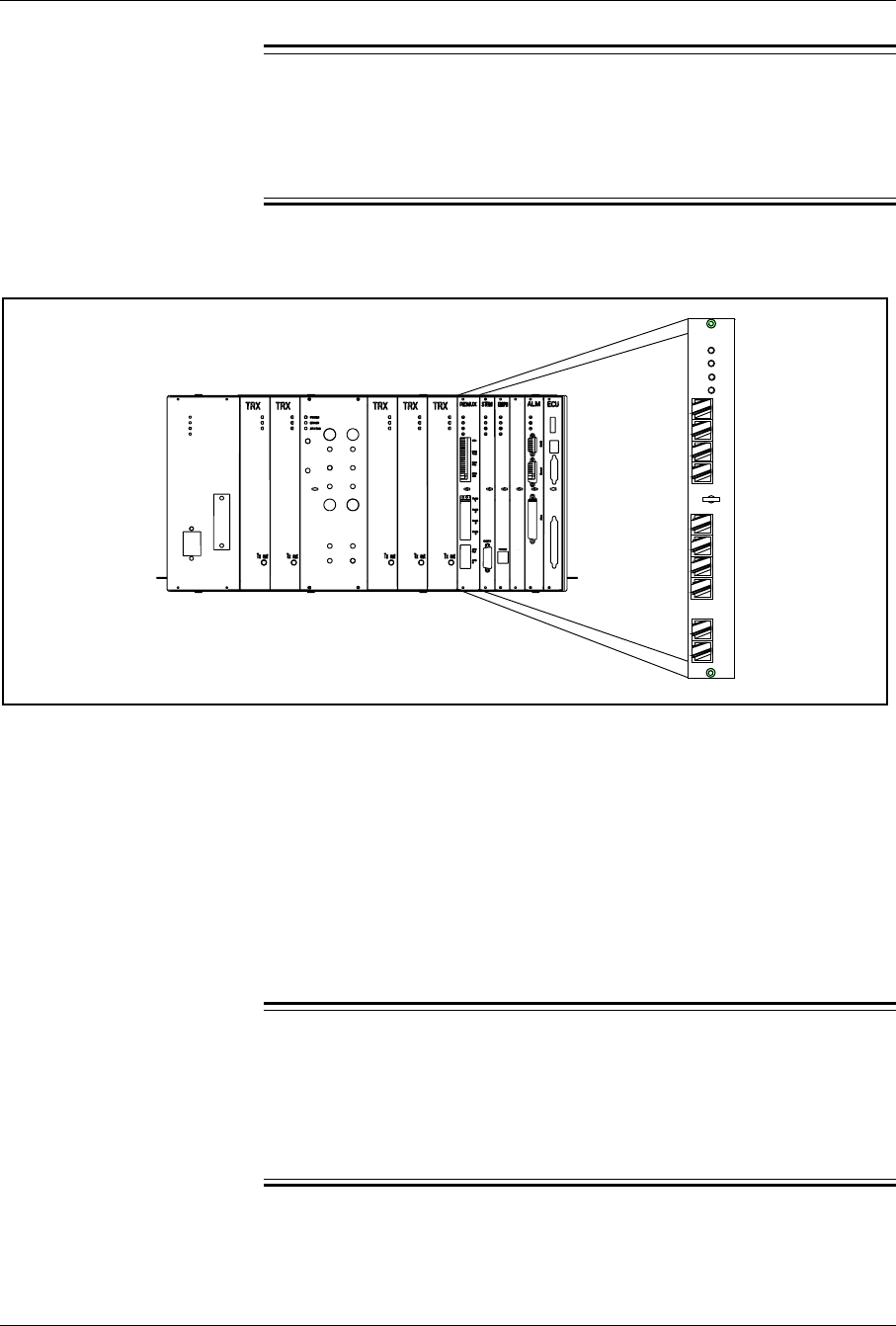
Hardware Replacement
4.
Warning!
Check that the REMUX status LEDs (see Figure 5-10 on page 5-21)
and all TRX status LEDs (see Figure 5-14 on page 5-31) in all
cabinets are off.
If any of the mentioned status LEDs are on or flashing, contact the
MSC.
ANP/RFTL
PCM
Test
TLINK
1
TLINK
2
TLINK
3
TLINK
4
REMUX
Power
Error
V24
PCM
Prim
PCM
Sec
AFS
In
AFS
Out
Status 1
Status 2
Figure 5-10. The REMUX Unit
5. Attach the ESD strap to your wrist and connect the free end of the
strap cable to an appropriate ground conductor in the cabinet.
6. Make a note of the cables connected to the unit.
7. Disconnect the cables from the unit.
8. Use the torque wrench with the Torx bit TX10 to loosen the screws
on the front of the unit.
9.
Warning!
The slot in the cabinet must not be left empty for an extended period
of time. If there is any delay in installing the hardware replacement
unit, then a blank panel (Blank 12M) must be screwed into the slot
position (or the old unit left in position).
Pull out the unit, using the extractor tool, and place it in an ESD
bag. Save the extractor hole plug. Replace the plug after installing
or replacing unit.
2/1551-EN/LZB 119 3312 Uae Rev PA4 1998-10-05 5-21

Hardware Replacement
Unit Hardware Replacement
10. Remove the hardware replacement unit from its ESD bag and set its
switches to match those on the old unit.
The switch settings are described in the Installation part Setting
the Unit Switches.
11. Carefully slide the replacement unit into the cabinet in place of the
old unit. Push the unit firmly into the backplane connector.
12. Use the torque wrench with the Torx bit TX10 to tighten the screws
on the front.
Turn the torque wrench until it slides to tighten to 0.6 Nm.
13. Check that the green power LED on the unit is on and the red error
LED is off. If this is not the case, refer to the troubleshooting
procedure in Section 4 on page 5-6 for detection of units suspected
to be faulty.
14. Connect the cables that were disconnected in Step 7 on page 5-21 to
the unit.
If you are not sure of how the cables were connected, see the
Installation part External Cable Installation (external cables)
and Appendix C (internal cables).
15. The REMUX requires approximately 20 minutes to synchronize. If
the RBS 884 Micro (1900 MHz) does not become operational after
20 minutes, issue a software repair command to the STRM. The
command is RECEI.
16. Inform the MSC that the unit has been replaced, so that they can
perform a test.
17. Remove the ESD strap cable from the cabinet, and detach it from
your wrist.
18. Close the cabinet door.
Unit Repair
19. Complete the Repair Traveler Note and attach it to the unit suspected
to be faulty.
20. Pack the unit in the packing material from the new unit and return it
to your local service center.
Plant Specification update
21. Update the Plant Specification in the Site Installation Documentation
concerning the new unit: use the comments field to note the date of
hardware replacement and new R-state.
5-22 2/1551-EN/LZB 119 3312 Uae Rev PA4 1998-10-05

Hardware Replacement
6.4 STRM Unit Replacement
Unit Removal
Warning!
The following procedure will disable the RBS 884 Micro (1900
MHz). The unit will be out of service during the procedure. Contact
the MSC before performing the following procedure. This procedure
will also disable any additional sectors and cascaded RBS systems.
1. Get permission from the MSC to replace the unit.
2. Open the cabinet door as described in the steps beginning with Step
1 on page 5-7.
3.
Warning!
A unit must never be replaced with another with a lower R-state
number.
Check that the hardware replacement unit is the same type as the unit
to be replaced, and that it has the same or higher R-state number.
4.
Warning!
Check that the STRM status LEDs (see Figure 5-11 on page 5-24)
and all TRX status LEDs (see Figure 5-14 on page 5-31) in all
cabinets are off.
If any of the mentioned status LEDs are on or flashing, contact the
MSC.
2/1551-EN/LZB 119 3312 Uae Rev PA4 1998-10-05 5-23
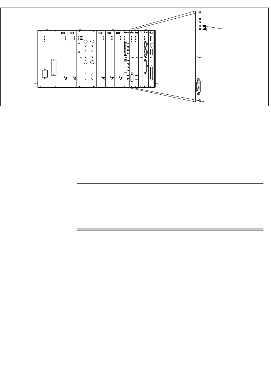
Hardware Replacement
Status LEDs
STRM
Power
Error
Status 1
EMRPB
Status 2
OUT
ANP/RFTL
Figure 5-11. The STRM Unit
5. Attach the ESD strap to your wrist and connect the free end of the
strap cable to an appropriate ground conductor in the cabinet.
6. Disconnect the cable or terminator from the unit.
7. Use the torque wrench with the Torx bit TX10 to loosen the screws
on the front of the unit.
8.
Warning!
The slot in the cabinet must not be left empty for an extended period
of time. If there is any delay in installing the hardware replacement
unit, a blank panel (Blank 8M) must be screwed into the slot position.
Pull out the unit, using the extractor tool, and place it in an ESD
bag. Save the extractor hole plug. Replace the plug after installing
or replacing unit.
Hardware Replacement Unit
9. Remove the hardware replacement unit from its ESD bag
10. Carefully slide the replacement unit into the cabinet in place of the
old unit. Push the unit firmly into the backplane connector.
11. Use the torque wrench with the Torx bit TX10 to tighten the screws
on the front.
Turn the torque wrench until it slides to tighten to 0.6 Nm.
12. Check that the green power LED on the unit is on and the red error
LED is off. If this is not the case, refer to the troubleshooting
procedure in Section 4 on page 5-6 for detection of units suspected
to be faulty.
5-24 2/1551-EN/LZB 119 3312 Uae Rev PA4 1998-10-05

Hardware Replacement
13. Reconnect the cable or terminator that was disconnected earlier.
14. If the RBS 884 Micro (1900 MHz) does not become operational,
cycle the power to the cabinet to reload the software.
15. Inform the MSC that the unit has been replaced, so that they can
perform a test.
16. Remove the ESD strap cable from the cabinet, and detach it from
your wrist.
17. Close the cabinet door.
Unit Repair
18. Complete the Repair Traveler Note and attach it to the unit suspected
to be faulty.
19. Pack the unit in the packing material from the new unit and return it
to your local service center.
Plant Specification update
20. Update the Plant Specification in the Site Installation Documentation
concerning the new unit: use the comments field to note the date of
hardware replacement and new R-state.
6.5 CONN Unit Replacement
Unit Removal
Warning!
The following procedure will disable the RBS 884 Micro (1900
MHz). The unit will be out of service during the procedure. Contact
the MSC before performing the following procedure.
1. Get permission from the MSC to replace the unit.
2. Open the cabinet door as described in the steps beginning with Step
1 on page 5-7.
2/1551-EN/LZB 119 3312 Uae Rev PA4 1998-10-05 5-25
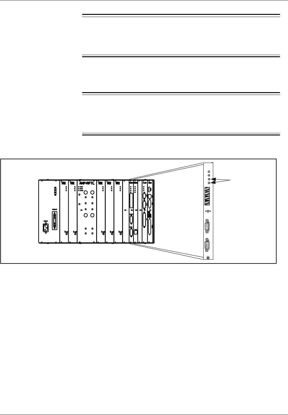
Hardware Replacement
3.
Warning!
A unit must never be replaced with another with a lower R-state
number.
Check that the hardware replacement unit is the same type as the unit
to be replaced, and that it has the same or higher R-state number.
4.
Warning!
Check that all TRX status LEDs (see Figure 5-14 on page 5-31) in
the relevant cabinet are off.
If they are on or flashing, contact the MSC.
Power
Error
Status 2
IN
OUT
EMRPB
AFS
Out
AFS
In
TL 1
TL 2
Status 1
CONN
Status LEDs
Figure 5-12. The CONN Unit
5. Attach the ESD strap to your wrist and connect the free end of the
strap cable to an appropriate ground conductor in the cabinet.
6. Make a note of the cables connected to the unit.
7. Disconnect the cables from the unit.
8. Use the torque wrench with the Torx bit TX10 to loosen the screws
on the front of the unit.
5-26 2/1551-EN/LZB 119 3312 Uae Rev PA4 1998-10-05

Hardware Replacement
9.
Warning!
The slot in the cabinet must not be left empty for an extended period
of time. If there is any delay in installing the hardware replacement
unit, a blank panel (Blank 8M) must be screwed into the slot position.
Pull out the unit, using the extractor tool, and place it in an ESD
bag. Save the extractor hole plug. Replace the plug after installing
or replacing unit.
Hardware Replacement Unit
10. Remove the hardware replacement unit from its ESD bag.
11. Carefully slide the replacement unit into the cabinet in place of the
old unit. Push the unit firmly into the backplane connector.
12. Use the torque wrench with the Torx bit TX10 to tighten the screws
on the front.
Turn the torque wrench until it slides to tighten to 0.6 Nm.
13. Check that the green power LED on the unit is on and the red error
LED is off. If this is not the case, refer to the troubleshooting
procedure in Section 4 on page 5-6 for detection of units suspected
to be faulty.
14. Connect the cables that were disconnected earlier.
15. Inform the MSC that the unit has been replaced, so that they can
perform a test.
16. Remove the ESD strap cable from the cabinet, and detach it from
your wrist.
17. Close the cabinet door.
Unit Repair
18. Complete the Repair Traveler Note and attach it to the unit suspected
to be faulty.
19. Pack the unit in the packing material from the new unit and return it
to your local service center.
Plant Specification update
20. Update the Plant Specification in the Site Installation Documentation
concerning the new unit: use the comments field to note the date of
hardware replacement and new R-state.
2/1551-EN/LZB 119 3312 Uae Rev PA4 1998-10-05 5-27

Hardware Replacement
6.6 EMRPM Unit Replacement
Unit Removal
Warning!
The following procedure will disable the RBS 884 Micro (1900
MHz). The unit will be out of service during the procedure. Contact
the MSC before performing the following procedure.
1. Get permission from the MSC to replace the unit.
2. Open the cabinet door as described in the steps beginning with Step
1 on page 5-7.
3.
Warning!
A unit must never be replaced with another with a lower R-state
number.
Check that the hardware replacement unit is the same type as the unit
to be replaced, and that it has the same or higher R-state number.
4.
Warning!
Check that the EMRPM status LEDs (see Figure 5-13 on page 5-29)
and all TRX status (see Figure 5-14 on page 5-31) in the relevant
cabinet are off. If any main cabinet EMRPM is to be changed, all
TRX status LEDs in all cabinets have to be checked.
If any of the mentioned status LEDs are on or flashing, contact the
MSC.
5-28 2/1551-EN/LZB 119 3312 Uae Rev PA4 1998-10-05
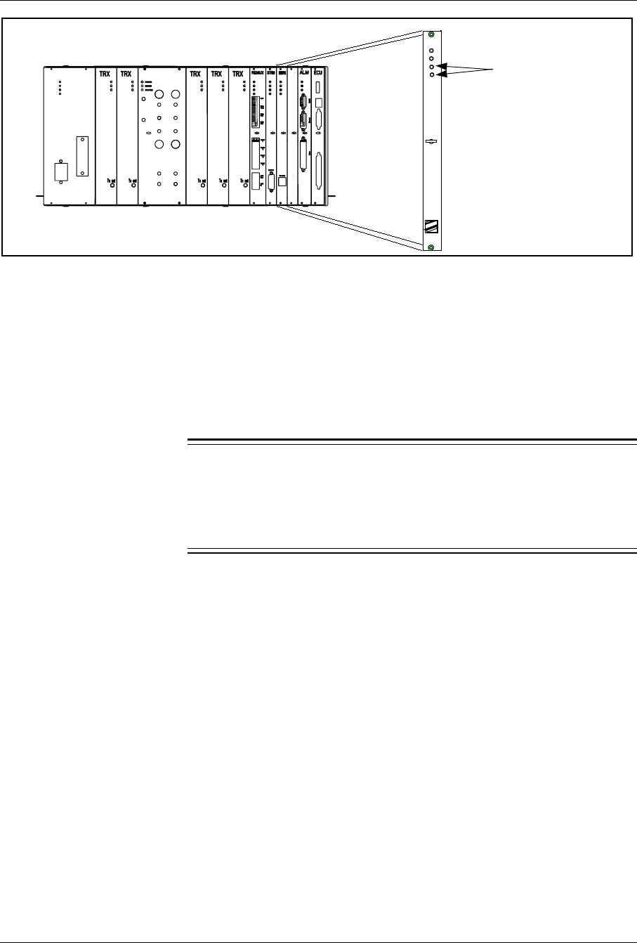
Hardware Replacement
Status LEDs
Power
Error
Status 1
Status 2
TW/DEB
ANP/RFTL
Figure 5-13. An EMRPM Unit
5. Attach the ESD strap to your wrist and connect the free end of the
strap cable to an appropriate ground conductor in the cabinet.
6. Disconnect the cables from the unit.
7. Use the torque wrench with the Torx bit TX10 to loosen the screws
on the front of the unit.
8.
Warning!
The slot in the cabinet must not be left empty for an extended period
of time. If there is any delay in installing the hardware replacement
unit, a blank panel (Blank 8M) must be screwed into the slot position.
Pull out the unit, using the extractor tool, and place it in an ESD
bag. Save the extractor hole plug. Replace the plug after installing
or replacing unit.
Unit hardware replacement
9. Remove the replacement unit from its ESD bag and set its switches
to match those on the old unit.
The EMRPM unit has an address switch. The settings are
described in Installation,Setting the Unit Switches.
10. Carefully slide the replacement unit into the cabinet in place of the
old unit. Push the unit firmly into the backplane connector.
11. Use the torque wrench with the Torx bit TX10 or TX8 to tighten the
screws on the front.
Turn the torque wrench until it slides to tighten to 0.6 Nm.
2/1551-EN/LZB 119 3312 Uae Rev PA4 1998-10-05 5-29

Hardware Replacement
12. Check that the green power LED on the unit is on and the red error
LED is off. If this is not the case, refer to the troubleshooting
procedure in Section 4 on page 5-6 for detection of units suspected
to be faulty.
13. If the RBS 884 Micro (1900 MHz) does not become operational after
five to eight minutes, cycle the power to the cabinet to reload the
software.
14. Inform the MSC that the unit has been replaced, so that they can
perform a test.
15. Remove the ESD strap cable from the cabinet, and detach it from
your wrist.
16. Close the cabinet door.
Unit Repair
17. Complete the Repair Traveler Note and attach it to the unit suspected
to be faulty.
18. Pack the unit in the packing material from the new unit and return it
to your local service center.
Plant Specification update
19. Update the Plant Specification in the Site Installation Documentation
concerning the new unit: use the comments field to note the date of
hardware replacement and new R-state.
6.7 TRX Unit Replacement
Unit Removal
1. Get permission from the MSC to replace the unit.
2. Open the cabinet door as described in the steps beginning with Step
1 on page 5-7.
3.
Warning!
A unit must never be replaced with another with a lower R-state
number.
Check that the hardware replacement unit is the same type as the unit
to be replaced, and that it has the same or higher R-state number.
5-30 2/1551-EN/LZB 119 3312 Uae Rev PA4 1998-10-05
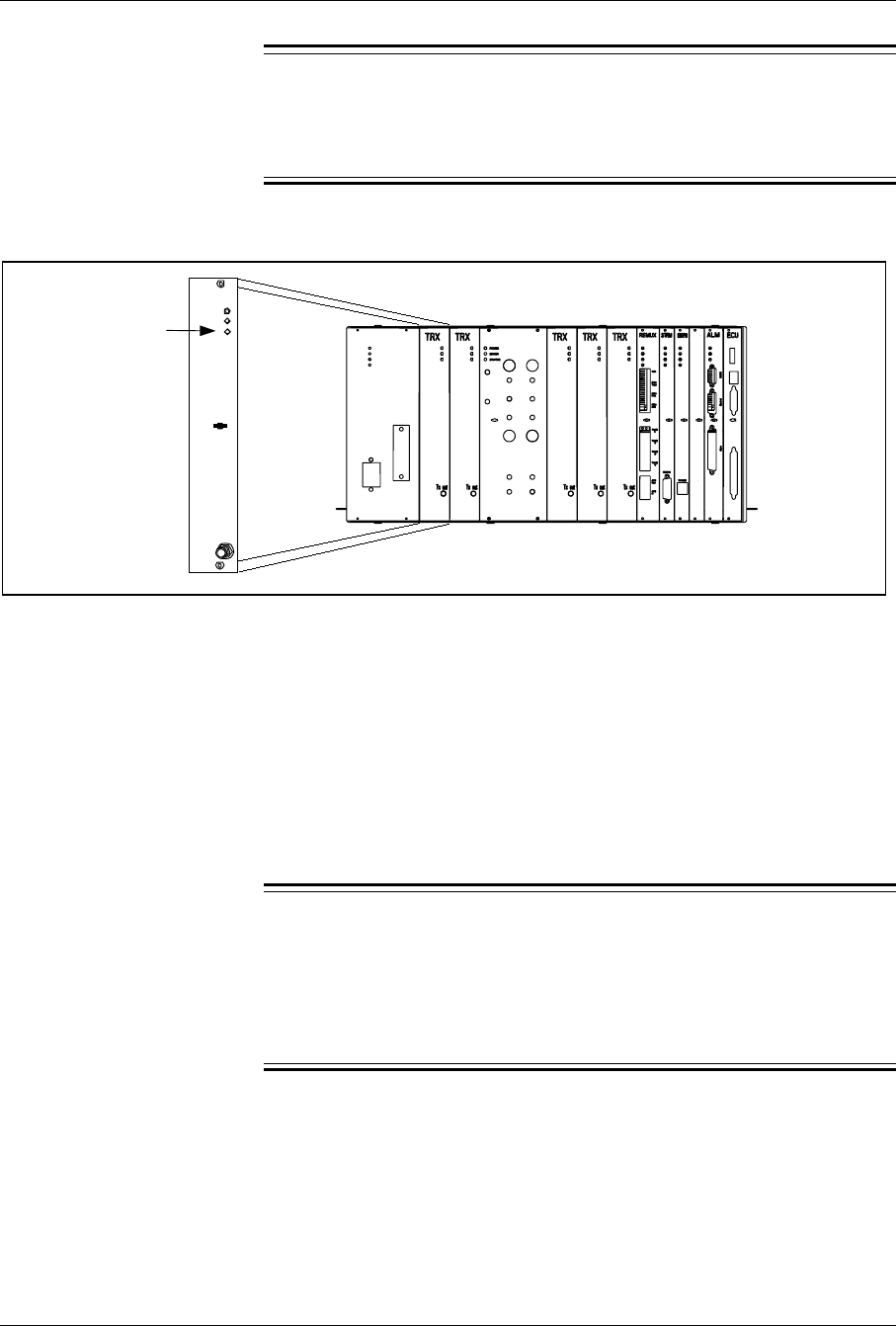
Hardware Replacement
4.
Warning!
Check that the status LED on the TRX to be replaced (see Figure
5-14 on page 5-31) is off.
If it is on or flashing, contact the MSC.
Status LED ANP/RFTL
Tx Out
Power
Error
Status
1900M
TRX
Figure 5-14. A TRX Unit
5. Attach the ESD strap to your wrist and connect the free end of the
strap cable to an appropriate ground conductor in the cabinet.
6. Disconnect the cable from the unit, using the torque wrench with the
SMA tool.
7. Use the torque wrench with the Torx bit TX10 to loosen the screws
on the front of the unit.
8.
Warning!
The slot in the cabinet must not be left empty for an extended period
of time. If there is any delay in installing the hardware replacement
unit, an RMU (dummy TRX) must be installed or the old TRX left
in position.
Pull out the unit, using the extractor tool, and place it in an ESD
bag. Save the extractor hole plug. Replace the plug after installing
or replacing unit.
Unit hardware replacement
9. Remove the hardware replacement unit from its ESD bag.
2/1551-EN/LZB 119 3312 Uae Rev PA4 1998-10-05 5-31

Hardware Replacement
10. Carefully slide the replacement unit into the cabinet in place of the
old unit. Push the unit firmly into the backplane connector.
11. Use the torque wrench with the Torx bit TX10 to tighten the screws
on the front.
Turn the torque wrench until it slides to tighten to 0.6 Nm.
12. Check that the green power LED on the unit is on and the red error
LED is off. If this is not the case, refer to the troubleshooting
procedure in Section 4 on page 5-6 for detection of units suspected
to be faulty.
13. Connect the cable that was disconnected earlier.
When attaching the cable connector to the connector on the
unit, hand-tighten as much as possible. Thereafter, fully tighten
using the torque wrench with the SMA tool. When turning the
torque wrench until it slides, the connector is tightened with
the torque 0.6 Nm.
14. Inform the MSC that the unit has been replaced, so that they can
perform a test.
15. Remove the ESD strap cable from the cabinet, and detach it from
your wrist.
16. Close the cabinet door.
Unit Repair
17. Complete the Repair Traveler Note and attach it to the unit suspected
to be faulty.
18. Pack the unit in the packing material from the new unit and return it
to your local service center.
Note: Do not dispose of the TRX unit. Its components
contain beryllium oxide.
Plant Specification update
19. Update the Plant Specification in the Site Installation Documentation
concerning the new unit: use the comments field to note the date of
hardware replacement and new R-state.
5-32 2/1551-EN/LZB 119 3312 Uae Rev PA4 1998-10-05

Hardware Replacement
6.8 ANP/RFTL Unit Replacement
Unit Removal
Warning!
The following procedure will disable the RBS 884 Micro (1900
MHz). The unit will be out of service during the procedure. Contact
the MSC before performing the following procedure.
1. Get permission from the MSC to replace the unit.
2. Open the cabinet door as described in the steps beginning with Step
1 on page 5-7.
3.
Warning!
A unit must never be replaced with another with a lower R-state
number.
Check that the hardware replacement unit is the same type as the unit
to be replaced, and that it has the same or higher R-state number.
4.
Warning!
Check that the status LED on the unit to be replaced (see Figure
5-15 on page 5-34) is off.
If it is on or flashing, contact the MSC.
2/1551-EN/LZB 119 3312 Uae Rev PA4 1998-10-05 5-33
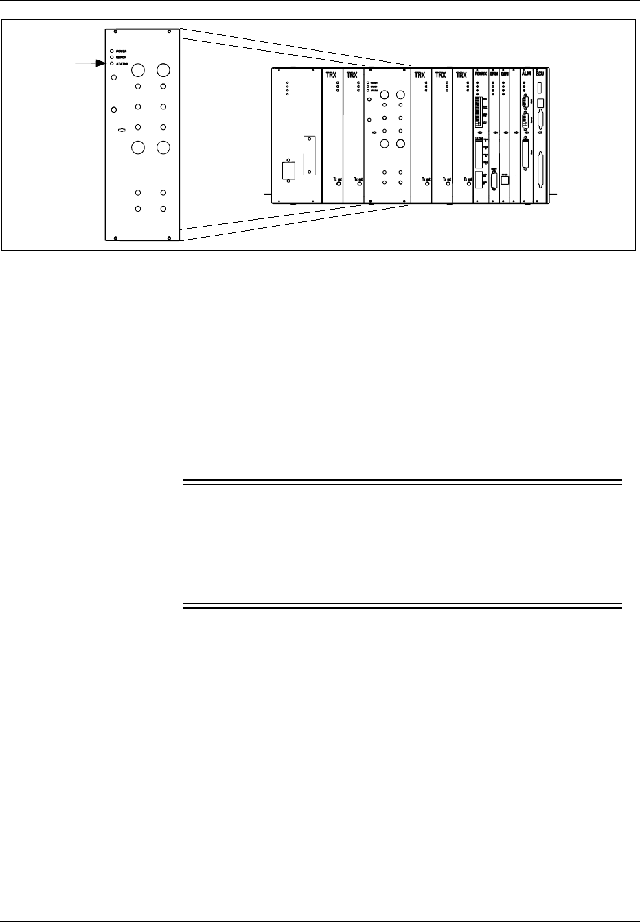
Hardware Replacement
Status LED ANP/RFTL
ANP/RFTL
Figure 5-15. The ANP/RFTL Unit
5. Attach the ESD strap to your wrist and connect the free end of the
strap cable to an appropriate ground conductor in the cabinet.
6. Make a note of the cables connected to the unit.
7. Disconnect the cables from the unit. Disconnect antenna cables by
hand. Use the torque wrench with the SMA tool for other cables.
8. Use the torque wrench with the Torx bit TX10 or TX8 to loosen the
screws on the front of the unit.
9.
Warning!
The slot in the cabinet must not be left empty for an extended period
of time. If there is any delay in installing the hardware replacement
unit, leave the old unit in the slot until the replacement unit is
available.
Pull out the unit, using the extractor tool, and place it in an ESD
bag. Save the extractor hole plug. Replace the plug after installing
or replacing unit.
Unit Hardware Replacement
10. Remove the hardware replacement unit from its ESD bag.
11. Carefully slide the replacement unit into the cabinet in place of the
old unit. Push the unit firmly into the backplane connectors.
12. Use the torque wrench with the Torx bit TX10 to tighten the screws
on the front.
Turn the torque wrench until it slides to tighten to 0.6 Nm.
5-34 2/1551-EN/LZB 119 3312 Uae Rev PA4 1998-10-05

Hardware Replacement
13. Check that the green power LED on the unit is on and the red error
LED is off. If this is not the case, refer to the troubleshooting
procedure in Section 4 on page 5-6 for detection of units suspected
to be faulty.
14. Connect the cables that were disconnected earlier.
When attaching the cable connector to the connector on the
unit, hand-tighten as much as possible. Fully tighten SMA
connectors using the torque wrench with the SMA tool. Turn
the torque wrench until it slides. The torque wrench tightens
the connector to a torque of 0.6 Nm. Hand tighten TNC
connectors. Do not use the torque wrench on TNC connectors.
If you are not sure of how the cables were connected, see the
Installation part External Cable Installation (external cables)
and Appendix C (internal cables).
15. Inform the MSC that the unit has been replaced, so that they can
perform a test.
16. Remove the ESD strap cable from the cabinet, and detach it from
your wrist.
17. Close the cabinet door.
Unit Repair
18. Complete the Repair Traveler Note and attach it to the unit suspected
to be faulty.
19. Pack the unit in the packing material from the new unit and return it
to your local service center.
Plant Specification update
20. Update the Plant Specification in the Site Installation Documentation
concerning the new unit: use the comments field to note the date of
hardware replacement and new R-state.
6.9 Alarm (ALM) Unit Replacement
Unit Removal
1. Get permission from the MSC to replace the unit.
2. Open the cabinet door as described in the steps beginning with Step
1 on page 5-7.
2/1551-EN/LZB 119 3312 Uae Rev PA4 1998-10-05 5-35
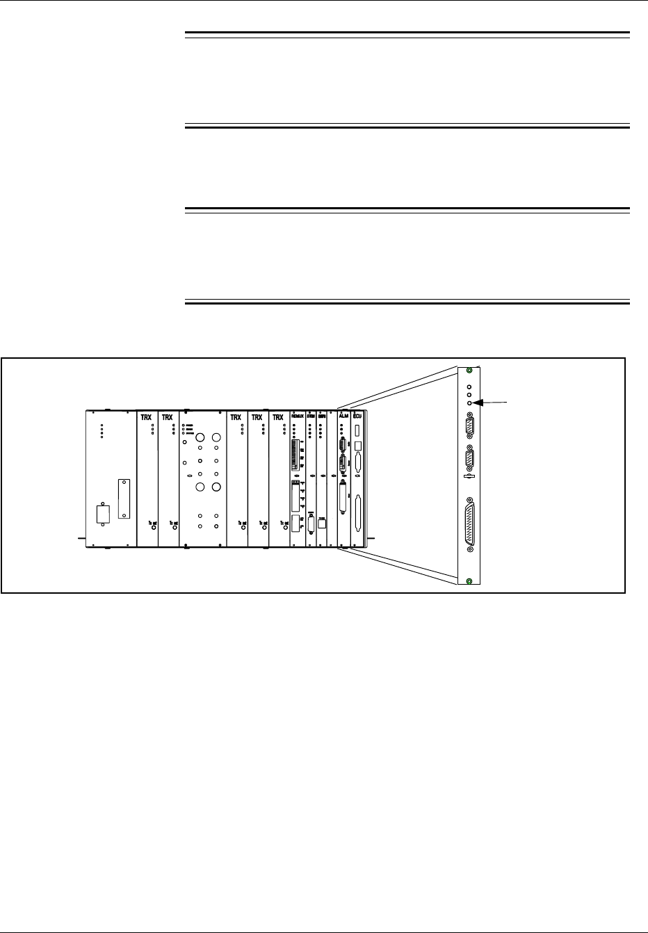
Hardware Replacement
3.
Warning!
A unit must never be replaced with another with a lower R-state
number.
Check that the hardware replacement unit is the same type as the unit
to be replaced, and that it has the same or higher R-state number.
4.
Warning!
Check that the status LED on the unit (see Figure 5-16 on page
5-36) is off.
If it is on or flashing, contact the MSC.
Status LED
ALM
Power
Error
Status
CLINK
Control
Alarm
ANP/RFTL
Figure 5-16. The Alarm Unit
5. Attach the ESD strap to your wrist and connect the free end of the
strap cable to an appropriate ground conductor in the cabinet.
6. Make a note of the cables connected to the unit.
7. Disconnect the cables from the unit.
8. Use the torque wrench with the Torx bit TX10 to loosen the screws
on the front of the unit.
Note: All External Alarms are disabled when the ALM
unit is blocked.
5-36 2/1551-EN/LZB 119 3312 Uae Rev PA4 1998-10-05

Hardware Replacement
9.
Warning!
The slot in the cabinet must not be left empty for an extended period
of time. If there is any delay in installing the hardware replacement
unit, a blank panel (Blank 10M) must be screwed into the slot
position.
Pull out the unit, using the extractor tool, and place it in an ESD
bag. Save the extractor hole plug. Replace the plug after installing
or replacing unit.
Unit Hardware Replacement
10. Remove the hardware replacement unit from its ESD bag.
11. Carefully slide the replacement unit into the cabinet in place of the
old unit. Push the unit firmly into the backplane connector.
12. Use the torque wrench with the Torx bit TX10 to tighten the screws
on the front.
Turn the torque wrench until it slides to tighten to 0.6 Nm.
13. Check that the green power LED on the unit is on and the red error
LED is off. If this is not the case, refer to the troubleshooting
procedure in Section 4 on page 5-6 for detection of units suspected
to be faulty.
14. Connect the cables that were disconnected earlier.
15. Inform the MSC that the unit has been replaced, so that they can
perform a test.
16. Remove the ESD strap cable from the cabinet, and detach it from
your wrist.
17. Close the cabinet door.
Unit Repair
18. Complete the Repair Traveler Note and attach it to the unit suspected
to be faulty.
19. Pack the unit in the packing material from the new unit and return it
to your local service center.
2/1551-EN/LZB 119 3312 Uae Rev PA4 1998-10-05 5-37

Hardware Replacement
Plant Specification update
20. Update the Plant Specification in the Site Installation Documentation
concerning the new unit: use the comments field to note the date of
hardware replacement and new R-state.
6.10 Environmental Control Unit (ECU) Replacement
Unit Removal
Warning!
The following procedure will disable the RBS 884 Micro (1900
MHz). The unit will be out of service during the procedure. Contact
the MSC before performing the following procedure.
1. Get permission from the MSC to replace the unit.
2. Open the cabinet door as described in the steps beginning with Step
1 on page 5-7.
3.
Warning!
A unit must never be replaced with another with a lower R-state
number.
Check that the hardware replacement unit is the same type as the unit
to be replaced, and that it has the same or higher R-state number.
4. Refer to Figure 5-17 on page 5-39)
5-38 2/1551-EN/LZB 119 3312 Uae Rev PA4 1998-10-05
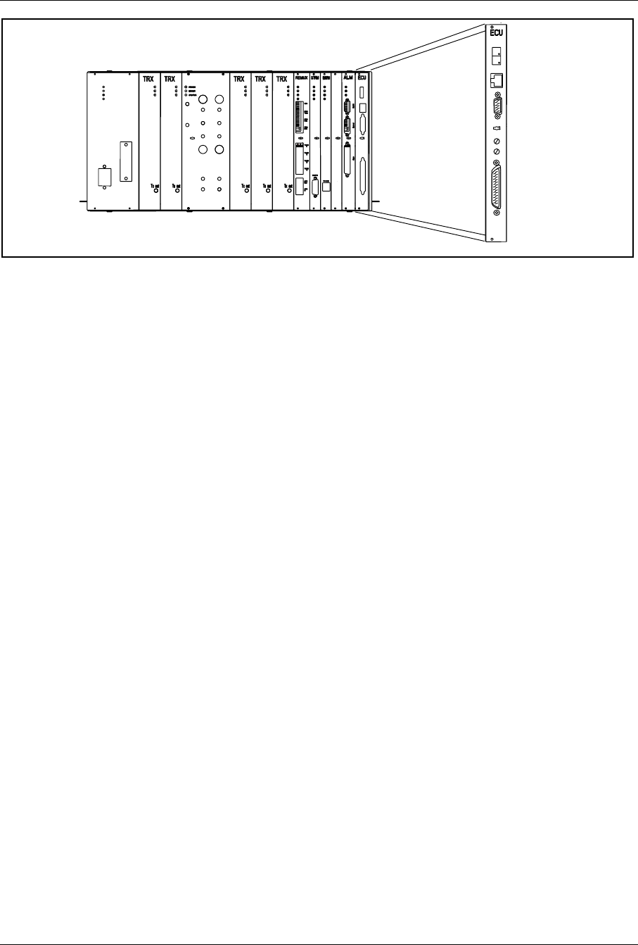
Hardware Replacement
ANP/RFTL
Figure 5-17. Environmental Control Unit (ECU)
5. Attach the ESD strap to your wrist and connect the free end of the
strap cable to an appropriate ground conductor in the cabinet.
6. Turn off the ECU circuit breaker.
7. Make a note of the cables connected to the unit.
8. Disconnect the cables from the unit.
9. Use the torque wrench with the Torx bit TX10 to loosen the screws
on the front of the unit.
10. Pull out the unit, using the extractor tool, and place it in an ESD
bag. If required, remove the handle of the extractor tool. Save the
extractor hole plug. Replace the plug after installing or replacing unit.
Unit Hardware Replacement
11. Remove the hardware replacement unit from its ESD bag.
12. Carefully slide the replacement unit into the cabinet in place of the
old unit. Push the unit firmly into the backplane connector.
13. Use the torque wrench with the Torx bit TX10 to tighten the screws
on the front.
Turn the torque wrench until it slides to tighten to 0.6 Nm.
14. Connect the cables that were disconnected earlier.
15. Turn on the ECU circuit breaker.
16. After fan test is complete, verify the decimal points located in the
two digit display are illuminated. If not, refer to the troubleshooting
procedure in Section 4 on page 5-6 for detection of units suspected
to be faulty.
2/1551-EN/LZB 119 3312 Uae Rev PA4 1998-10-05 5-39

Hardware Replacement
17. Remove the ESD strap cable from the cabinet, and detach it from
your wrist.
18. Close the cabinet door.
Unit Repair
19. Complete the Repair Traveler Note and attach it to the unit suspected
to be faulty.
20. Pack the unit in the packing material from the new unit and return it
to your local service center.
Plant Specification update
21. Update the Plant Specification in the Site Installation Documentation
concerning the new unit: use the comments field to note the date of
hardware replacement, and new R-state.
6.11 Fan Replacement
Unit Removal
1. Get permission from the MSC to replace the unit.
2. Open the cabinet door as described in the steps beginning with Step
1 on page 5-7.
3. Pull out the two plungers in the top cap and lift cap up until the top
brace limits travel. Lower cap slightly while pushing the support
brace towards the rear of the cabinet. Ensure the support brace
engages the mating bracket
4. Identify the failed fan unit.
5.
Warning!
A unit must never be replaced with another with a lower R-state
number.
Check that the hardware replacement unit is the same type as the unit
to be replaced, and that it has the same or higher R-state number.
5-40 2/1551-EN/LZB 119 3312 Uae Rev PA4 1998-10-05
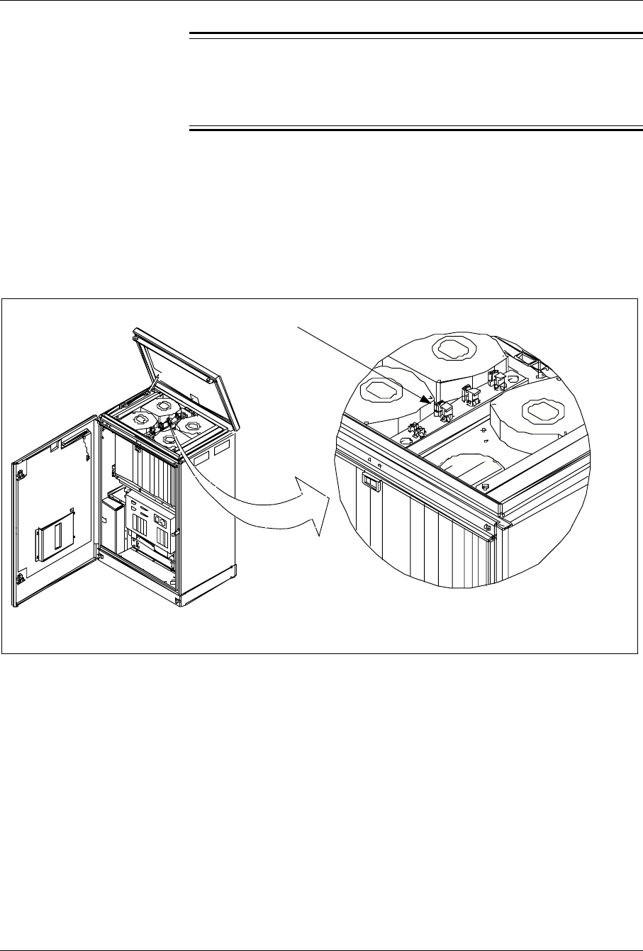
Hardware Replacement
6.
Warning!
The remaining steps in this procedure must be performed as quickly
as possible in order to avoid overheating the cabinet.
Disconnect the cable from the unit.
7. Inform the MSC that the unit has been replaced, so that they can
perform a test.
8. Disconnect the three-wire connector. See Figure 5-18 on page 5-41.
9. Disconnect the two-wire connector.
Fan Connectors
Figure 5-18. The Fan Unit
10. Remove the tie wraps securing the fan wiring.
11. Remove the three screws that secure the fan unit to the cabinet frame.
12. Remove the fan unit.
Unit Hardware Replacement
13. Remove the replacement fan unit.
14. Install new fan unit and replace three mounting screws.
15. Replace tie wraps if required.
2/1551-EN/LZB 119 3312 Uae Rev PA4 1998-10-05 5-41

Hardware Replacement
16. Reconnect the two-wire fan connector.
17. Reconnect the three-wire fan connector.
18. Cycle the fan breaker (turn off and turn on) to reset the fan alarm.
The fan start-up sequence will be initiated.
19. If the new fan does not start, refer to the troubleshooting procedure
in Section 4 on page 5-6 for detection of units suspected to be faulty.
20. Close the top cap by disengaging the support brace. Press down
firmly on the top cap until the two plungers engage the slots on the
cabinet.
Note: Press the plungers toward rear of cabinet to ensure
proper plunger seating.
21. Close the cabinet door.
22. Inform the MSC that the unit has been replaced.
Unit Repair
23. Complete the Repair Traveler Note and attach it to the unit suspected
to be faulty.
24. Pack the unit in the packing material from the new unit and return it
to your local service center.
Plant Specification update
25. Update the Plant Specification in the Site Installation Documentation
concerning the new unit: use the comments field to note the date of
hardware replacement and new R-state.
6.12 Main Heater Replacement
Warning!
The following procedure will disable the RBS 884 Micro (1900 MHz).
The unit will be out of service during the procedure. Contact the MSC
before performing the following procedure.
Unit Removal
1. Get permission from the MSC to replace the unit.
2. Open the cabinet door as described in the steps beginning with Step
1 on page 5-7.
5-42 2/1551-EN/LZB 119 3312 Uae Rev PA4 1998-10-05
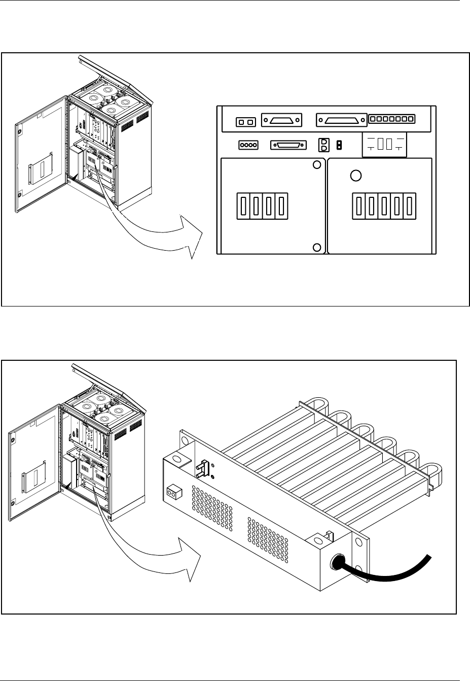
Hardware Replacement
3. Place the MAIN HTR circuit breaker on the right side of the AC/DC
Distribution Box in the OFF position. See Figure 5-19 on page 5-43
ALM CABLE ECU CABLE
SUBRK PWR
FAN PWR CSU
SENSORS
AC
CONNECTED
MAIN PSU MAIN
HTR BAT
HTR GFI
OUTLET
BAT ECU CSU FANS
BAT COMP
BAT
ALM DOOR
ALM
ON
OFF
Figure 5-19. AC/DC Distribution Box
4. Locate the Main Heater Assembly. See Figure 5-20 on page 5-43.
Figure 5-20. Subrack Heater
2/1551-EN/LZB 119 3312 Uae Rev PA4 1998-10-05 5-43

Hardware Replacement
5. Check that the heater assembly is the same type as the unit to be
replaced.
6. Unplug the heater control wires from the front of the heater assembly.
7. Remove the two screws located on the top of the perforated heater
assembly cover. Remove the cover and retain for installation on
replacement unit.
8. Remove the mounting screws located on each side of the heater
assembly (two per side). Pull the heater assembly out four to six
centimeters.
9.
Warning!
Use a voltmeter to verify the unit is NOT energized. Do not assume
power is OFF.
Locate the heater power cable on the right side of the heater
assembly. Follow cable into the heater assembly and locate the
black, white, and green power wires.
Note: If required, remove any ties or clamps securing
power wires.
10. Disconnect the black, white, and green power wires. If needed,
record wire position and connections.
11. Remove the strain relief and remove the power cable from the heater
assembly. Remove heater assembly from cabinet.
Unit Hardware Replacement
12. Remove the replacement unit from any packing material.
13. Remove the two screws located on the top of the perforated heater
assembly cover. Remove the cover.
14. Insert new replacement heater assembly approximately eight to ten
centimeters into cabinet opening.
15. Insert power cable through right side of heater assembly.
16. Reconnect the black, white, and green power wires. The black wire
connects to the solid-state relay terminal (2). The white wire
connects to 1L1 and 1L2 with a wire nut. The green wire connects
to the heater assembly ground.
17. Replace the top cover and secure with two screws.
18. Insert the heater assembly all the way into the cabinet opening and
replace the mounting screws (two per side).
5-44 2/1551-EN/LZB 119 3312 Uae Rev PA4 1998-10-05

Hardware Replacement
19. Reconnect the heater control wires to front of heater assembly.
20. Place the MAIN HTR circuit breaker on the right side of the AC/
DC Distribution Box in the ON position.
21. Close the cabinet door.
22. Inform the MSC that the unit has been replaced.
Unit Repair
23. Complete the Repair Traveler Note and attach it to the unit suspected
to be faulty.
24. Pack the unit in the packing material from the new unit and return it
to your local service center.
Plant Specification update
25. Update the Plant Specification in the Site Installation Documentation
concerning the new unit: use the comments field to note the date of
hardware replacement and new R-state.
6.13 Battery Heater Replacement
Unit Removal
1. Get permission from the MSC to replace the unit.
2. Open the cabinet door as described in the steps beginning with Step
1 on page 5-7.
3. Place the BAT circuit breaker on the left side of the AC/DC
Distribution Box in the OFF position.
4. Place the BAT HTR circuit breaker on the right side of the AC/DC
Distribution Box in the OFF position. See Figure 5-21 on page 5-46
2/1551-EN/LZB 119 3312 Uae Rev PA4 1998-10-05 5-45
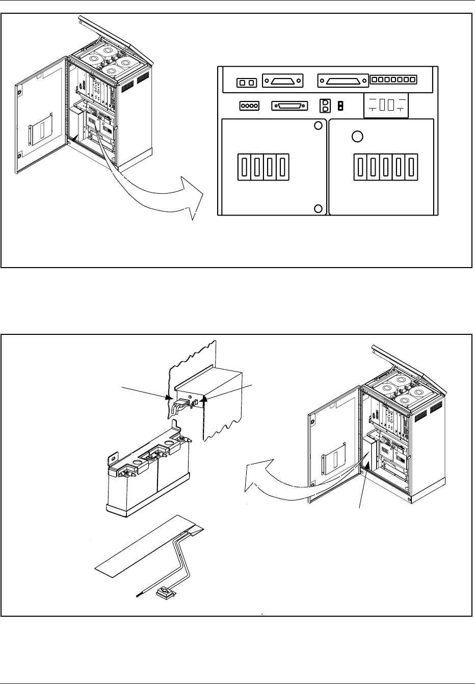
Hardware Replacement
ALM CABLE ECU CABLE
SUBRK PWR
FAN PWR CSU
SENSORS
AC
CONNECTED
MAIN PSU MAIN
HTR BAT
HTR GFI
OUTLET
BAT ECU CSU FANS
BAT COMP
BAT
ALM DOOR
ALM
ON
OFF
Figure 5-21. AC/DC Distribution Box
5. Locate the battery compartment. The battery heater is under the
battery tray. See Figure 5-22 on page 5-46.
Battery
Compartment
Failed Battery
Sensor connector
Power Connector
Figure 5-22. Location of Battery Heater
5-46 2/1551-EN/LZB 119 3312 Uae Rev PA4 1998-10-05
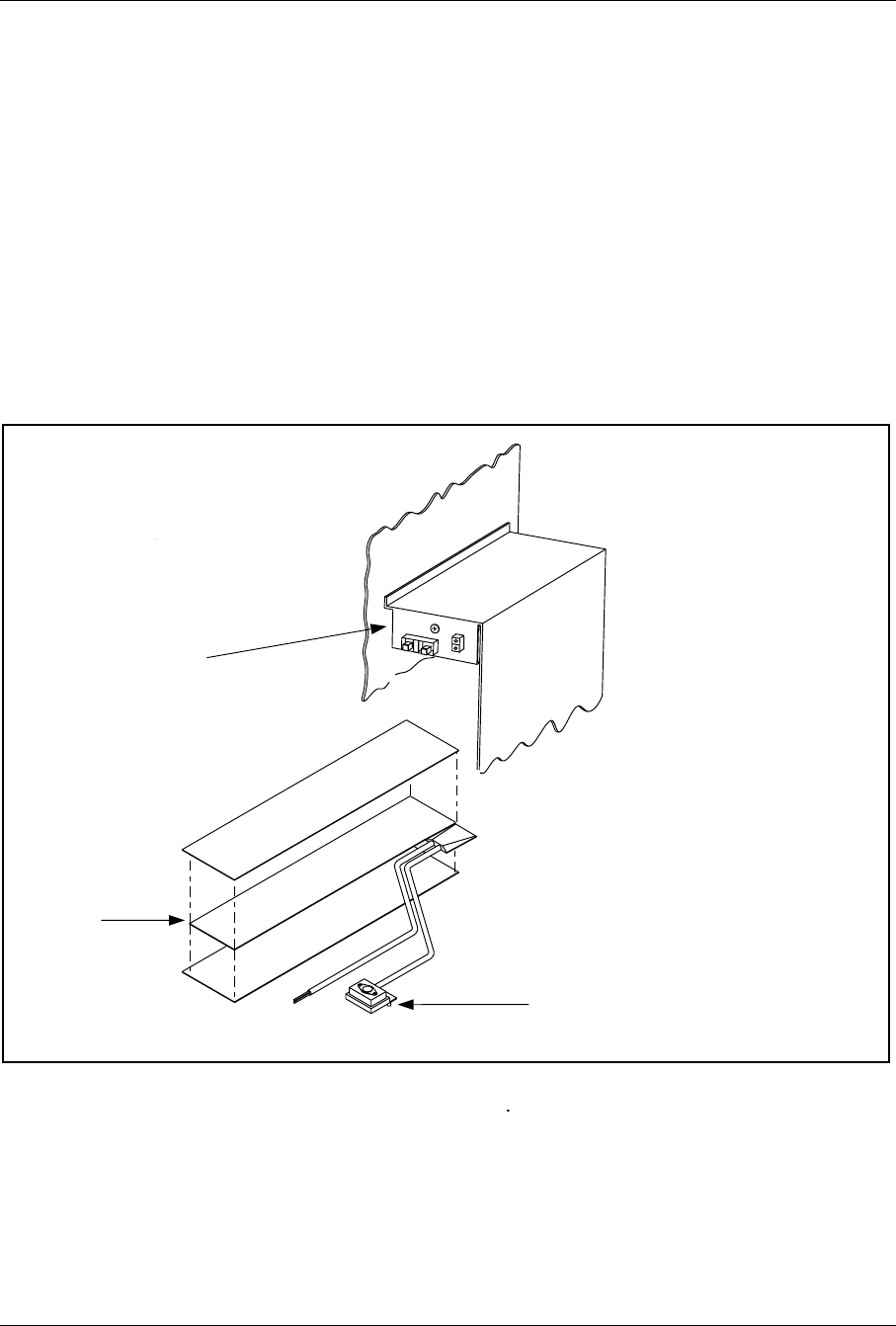
Hardware Replacement
6. Remove the four screws from the battery cover and remove the cover
from the battery compartment.
7. Disconnect the Failed Battery Sensor connector.
8. Disconnect the power connector of the battery cable assembly from
the connector at the top of the battery compartment.
9. Remove the hex nut on the hold-down bracket on the side wall of
the battery compartment. Remove the hold down bracket.
10. Remove the battery tray with the batteries from the battery
compartment.
11. Locate the battery compartment. The battery heater is under the
battery tray. See Figure 5-25 on page 5-50.
Heater Assembly
Electrical Connections
Located Inside
Enclosure
Thermostat
Heater
Figure 5-23. Battery Heater Assembly
12. Remove the screw on the front of the wiring enclosure located above
the battery compartment. Support the enclosure.
13. Pull the enclosure down and locate the two screws securing the
battery heater thermostat to bottom of enclosure.
2/1551-EN/LZB 119 3312 Uae Rev PA4 1998-10-05 5-47

Hardware Replacement
14. Remove the thermostat nuts and thermostat.
15. Remove the two heater power wires from the terminal strip inside
the enclosure. Remove the strain relief and pull the wires through
the bottom of the enclosure.
16. Remove the heater assembly from the cabinet.
Unit Hardware Replacement
17. Remove any packing material from the replacement heater assembly.
18. Push two heater power wires through strain relief and bottom of
enclosure. Connect wires to terminal strip.
19. Secure thermostat to bottom of enclosure with two screws removed
previously.
20. Raise enclosure and slide pins into holes. Secure enclosure to top of
battery compartment with screw removed previously.
21. Install the battery tray.
22. Install the hold-down bracket and the hex nut on the side wall of the
battery compartment.
23. Reconnect the power connector of the battery cable assembly to the
connector at the top of the battery compartment.
24. Reconnect the Failed Battery Sensor connector.
25. Install the battery compartment cover with the four screws removed
previously.
26. Place the BAT circuit breaker on the left side of the AC/DC
Distribution Box in the ON position.
27. Place the BAT HTR circuit breaker on the right side of the AC/DC
Distribution Box in the ON position.
28. Close the cabinet door.
29. Inform the MSC that the unit has been replaced.
Unit Repair
30. Complete the Repair Traveler Note and attach it to the unit suspected
to be faulty.
31. Pack the unit in the packing material from the new unit and return it
to your local service center.
5-48 2/1551-EN/LZB 119 3312 Uae Rev PA4 1998-10-05
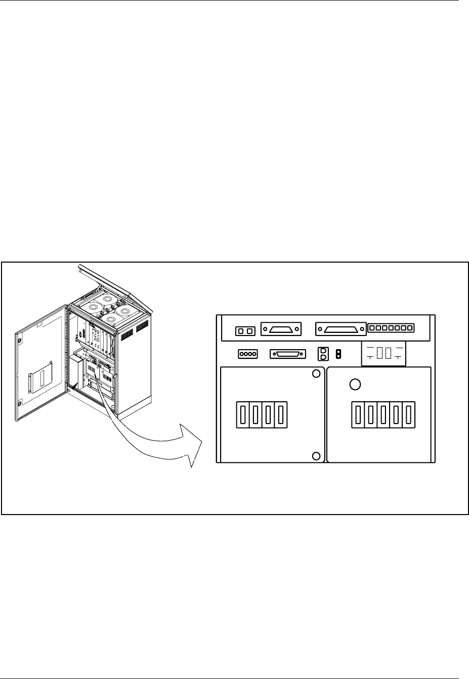
Hardware Replacement
Plant Specification update
32. Update the Plant Specification in the Site Installation Documentation
concerning the new unit: use the comments field to note the date of
hardware replacement, and new R-state.
6.14 Battery Replacement
Unit Removal
1. Get permission from the MSC to replace the unit.
2. Open the cabinet door as described in the steps beginning with Step
1 on page 5-7.
3. Place the BAT circuit breaker on the left side of the AC/DC
Distribution Box in the OFF position. See Figure 5-24 on page 5-49
ALM CABLE ECU CABLE
SUBRK PWR
FAN PWR CSU
SENSORS
AC
CONNECTED
MAIN PSU MAIN
HTR BAT
HTR GFI
OUTLET
BAT ECU CSU FANS
BAT COMP
BAT
ALM DOOR
ALM
ON
OFF
Figure 5-24. AC/DC Distribution Box
4. Locate the battery compartment. See Figure 5-25 on page 5-50.
2/1551-EN/LZB 119 3312 Uae Rev PA4 1998-10-05 5-49
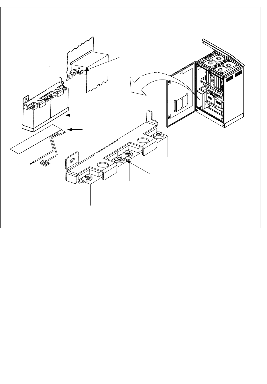
Hardware Replacement
+
+
-
-
Copper Strap
Battery 1
Battery 2
Battery Tray
Battery Heater
Failed Battery
Sensor Connector
Figure 5-25. Battery Assembly
5. Remove the four hex head screws from the battery cover and remove
the cover from the battery compartment.
6. Disconnect the Failed Battery Sensor connector.
7. Disconnect the power connector of the battery cable assembly from
the connector at the top of the battery compartment.
8. Remove the hex nut on the hold-down bracket on the side wall of
the battery compartment. Remove the hold down bracket.
9. Remove the battery tray with the batteries from the battery
compartment.
10. Disconnect one of the 18-gauge white wires labeled POST from the
negative terminal of battery 1. Disconnect the other 18-gauge white
wire from the negative terminal of battery 2.
5-50 2/1551-EN/LZB 119 3312 Uae Rev PA4 1998-10-05

Hardware Replacement
11. Disconnect the 8-gauge black cable from the negative terminal (-) of
battery 1.
12. Disconnect the 8-gauge red cable from the positive terminal (+) of
battery 2.
13. Remove the copper strap connecting the center terminals (positive
terminal of battery 1 to negative terminal of battery 2).
14. Remove the batteries from the battery tray.
15. Dispose of old batteries properly.
Unit Hardware Replacement
16. Remove the replacement batteries from the packing material.
17. Install the batteries into the battery tray as illustrated in Figure 5-25
on page 5-50. Place the hold-down bracket on the batteries.
18. Connect the center terminals (positive terminal of battery 1 to
negative terminal of battery 2) with the copper strap. Do not tighten
the negative terminal of battery 2 at this time.
19. Connect the 8-gauge black cable to the negative terminal (-) of
battery 1.
20. Connect the 8-gauge red cable to the positive terminal (+) of battery
2.
Note: Ensure the terminals are placed inward, toward the
back of the battery. Torque all bolts to 50 in-lbs.
21. Connect one of the 18-gauge white wires labeled POST to the
negative terminal of battery 1. Connect the other 18-gauge white
wire to the negative terminal of battery 2.
22. Install the battery tray with the batteries in the battery compartment.
Make sure the battery cable assembly is not pinched against the
battery compartment.
23. Place the hold-down bracket over the screw on the side wall of the
battery compartment. Secure with a hex nut.
24. Connect the power connector of the battery cable assembly to the
connector at the top of the battery compartment.
25. Connect the Failed Battery Sensor connector.
26. Install the battery cover on the battery compartment with the four
hex head screws.
27. Place the BATT circuit breaker on the left side of the AC/DC
Distribution Box in the ON position.
2/1551-EN/LZB 119 3312 Uae Rev PA4 1998-10-05 5-51

Hardware Replacement
Plant Specification update
28. Update the Plant Specification in the Site Installation Documentation
concerning the new unit: use the comments field to note the date of
hardware replacement and new R-state.
6.15 AC Surge Suppressor Replacement
Unit Removal
Warning!
The following procedure will disable the RBS 884 Micro (1900
MHz). The unit will be out of service during the procedure. Contact
the MSC before performing the following procedure.
1. Get permission from the MSC to replace the unit.
2. Open the cabinet door as described in the steps beginning with Step
1 on page 5-7.
3. Disconnect all power to the RBS 884 Micro (1900 MHz) cabinet.
4.
Warning!
Verify all power is removed from cabinet. Verify the AC
CONNECTED indicator light is off.
Place the MAIN circuit breaker on the right side of the AC/DC
Distribution Box in the OFF position. See Figure 5-26 on page 5-53
5-52 2/1551-EN/LZB 119 3312 Uae Rev PA4 1998-10-05
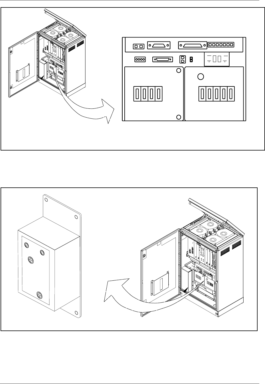
Hardware Replacement
ALM CABLE ECU CABLE
SUBRK PWR
FAN PWR CSU
SENSORS
AC
CONNECTED
MAIN PSU MAIN
HTR BAT
HTR GFI
OUTLET
BAT ECU CSU FANS
BAT COMP
BAT
ALM DOOR
ALM
ON
OFF
Figure 5-26. AC/DC Distribution Box
5. Open the front of the AC/DC Distribution Box and locate the AC
Surge Suppressor on back wall. See Figure 5-27 on page 5-53.
AC Surge Suppressor
Located on Rear Wall of
AC/DC Control Enclosure
PROTECTEDPOW
ERO
N
LINE
NEUTRAL
Figure 5-27. AC Surge Suppressor Assembly
6. Verify the LEDs on front of surge suppressor are off.
2/1551-EN/LZB 119 3312 Uae Rev PA4 1998-10-05 5-53

Hardware Replacement
7. Disconnect the LINE and NEUTRAL wires from the front of the
surge suppressor.
8. Remove the nuts securing the surge suppressor to rear wall. Remove
the surge suppressor.
Unit Hardware Replacement
9. Remove any packing material from the replacement unit.
10. Install new surge suppressor to rear wall of AC/DC Distribution Box
using nuts removed previously.
11. Reconnect the LINE and NEUTRAL wires to the front of the surge
suppressor.
12. Place the MAIN circuit breaker on the right side of the AC/DC
Distribution Box in the ON position.
13. Verify the LEDs on front of surge suppressor are on.
14. Close the AC/DC Distribution Box.
15. Close the cabinet door.
16. Inform the MSC that the unit has been replaced.
Unit Repair
17. Complete the Repair Traveler Note and attach it to the unit suspected
to be faulty.
18. Pack the unit in the packing material from the new unit and return it
to your local service center.
Plant Specification update
19. Update the Plant Specification in the Site Installation Documentation
concerning the new unit: use the comments field to note the date of
hardware replacement, and new R-state.
5-54 2/1551-EN/LZB 119 3312 Uae Rev PA4 1998-10-05
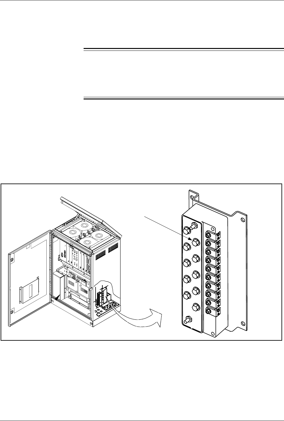
Hardware Replacement
6.16 T1(E1) PCM Primary Surge Suppressor Replacement
Unit Removal
Warning!
The following procedure will disable the RBS 884 Micro (1900
MHz). The unit will be out of service during the procedure. Contact
the MSC before performing the following procedure.
1. Get permission from the MSC to replace the unit.
2. Open the cabinet door as described in the steps beginning with Step
1 on page 5-7.
3. Locate the Primary Surge Suppressor on the right inside wall of
cabinet.
4. See Figure 5-28 on page 5-55.
12345
Located on Right Inside Wall
T1(E1) PCM Primary Surge
Suppressor Tube (10)
Figure 5-28. T1(E1) Primary Surge Suppressor
5. Remove the T1(E1) connections from the surge suppressor.
6. Remove the four nuts securing the surge suppressor to the cabinet.
remove the unit from the cabinet.
2/1551-EN/LZB 119 3312 Uae Rev PA4 1998-10-05 5-55

Hardware Replacement
Unit Hardware Replacement
7. Remove the replacement unit.
8. Install the replacement unit in the cabinet and replace the four nuts.
9. Reattach the T1 (E1) connections.
10. Close the cabinet door.
11. Inform the MSC that the unit has been replaced.
Unit Repair
12. Complete the Repair Traveler Note and attach it to the unit suspected
to be faulty.
13. Pack the unit in the packing material from the new unit and return it
to your local service center.
Plant Specification update
14. Update the Plant Specification in the Site Installation Documentation
concerning the new unit: use the comments field to note the date of
hardware replacement, and new R-state.
6.17 T1(E1) PCM Secondary Surge Suppressor Replacement
Unit Removal
Warning!
The following procedure will disable the RBS 884 Micro (1900
MHz). The unit will be out of service during the procedure. Contact
the MSC before performing the following procedure.
1. Get permission from the MSC to replace the unit.
2. Open the cabinet door as described in the steps beginning with Step
1 on page 5-7.
3. Locate the T1(E1) PCM Secondary Surge Suppressor. See Figure
5-29 on page 5-57.
5-56 2/1551-EN/LZB 119 3312 Uae Rev PA4 1998-10-05
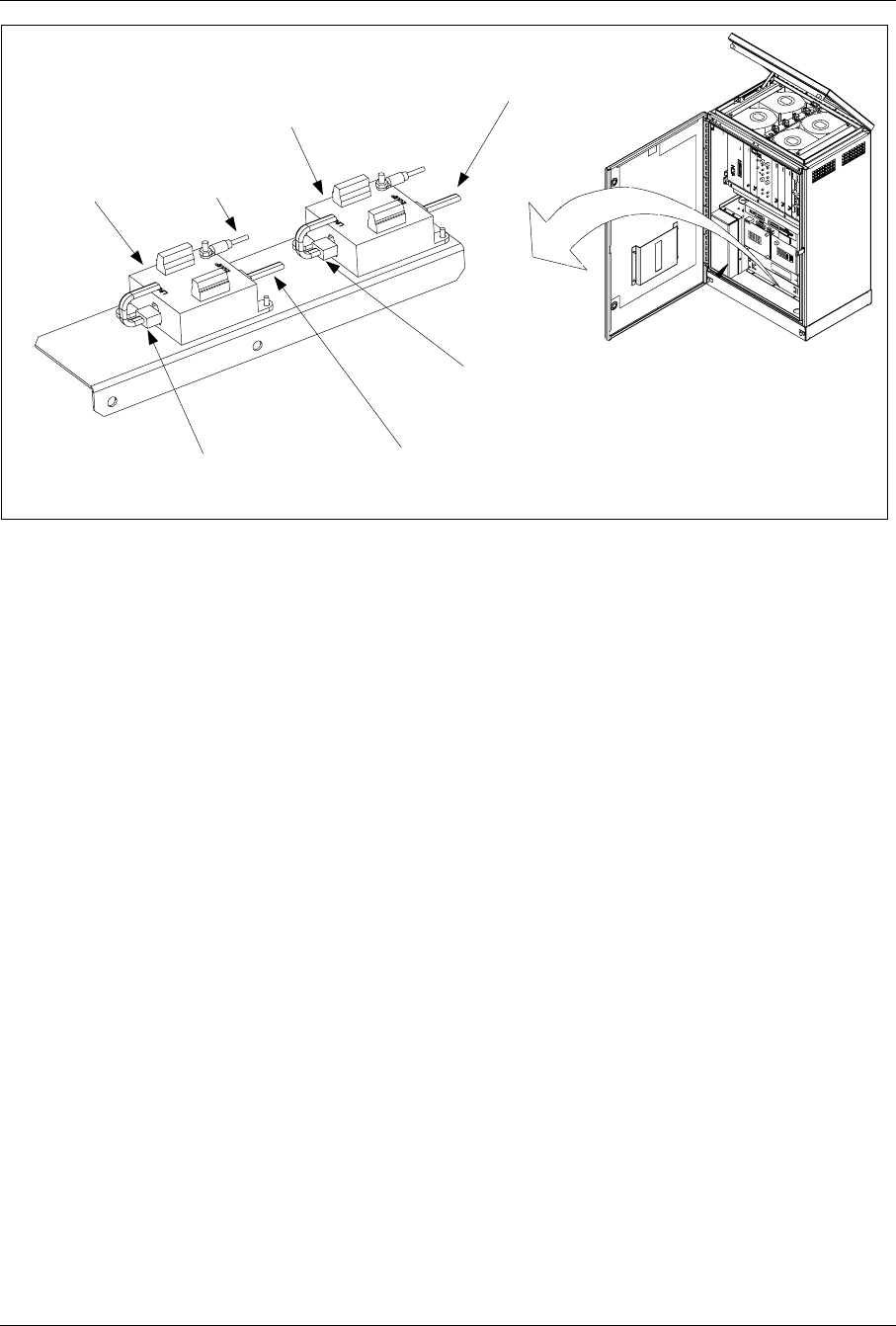
Hardware Replacement
T1(E1) PCM Secondary Surge
Suppressor is Located Below
the AC/DC Box.
Suppressor #2
(Optional)
Suppressor #1
Ground Wire
(to Gnd Plate)
T1(E1) PCM Shielded Cable
(From: Equip to: Subrack
REMUX "PCM PRIM")
T1(E1) PCM Shielded Cable
(From: Equip To: Subrack
REMUX "PCM SEC")
T1(E1) PCM Shielded Cable
(From: Line To: PSSI-J2)
T1(E1) PCM Shielded Cable
(From: Line To: PSSI-J1)
Figure 5-29. T1(E1) PCM Secondary Surge Suppressor Assembly
4. Remove the T1(E1) PCM shielded cables from the surge suppressor
to be replaced. Record position of cables if required.
5. Remove the ground wire.
6. Remove the two mounting screws (or nuts) and remove unit from the
cabinet.
Unit Hardware Replacement
7. Install replacement unit in cabinet and replace two mounting screws.
8. Reattach T1(E1) cables and ground wire.
9. Close the cabinet door.
10. Inform the MSC that the unit has been replaced.
Unit Repair
11. Complete the Repair Traveler Note and attach it to the unit suspected
to be faulty.
12. Pack the unit in the packing material from the new unit and return it
to your local service center.
2/1551-EN/LZB 119 3312 Uae Rev PA4 1998-10-05 5-57
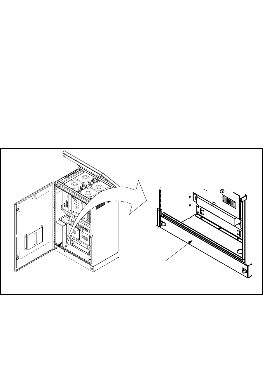
Hardware Replacement
Plant Specification update
13. Update the Plant Specification in the Site Installation Documentation
concerning the new unit: use the comments field to note the date of
hardware replacement, and new R-state.
6.18 Air Filter Replacement
Unit Removal
1. Get permission from the MSC to replace the unit.
2. Open the cabinet door as described in the steps beginning with Step
1 on page 5-7.
3. See Figure 5-30 on page 5-58.
Air Filter Located Behind
Cover Plate
Figure 5-30. Air Filter Location
4. Locate the lower air filter cover.
5. If equipped with slide latches, grasp the slide latches and move
outward. If equipped with screws, remove the screws. Remove the
cover and set aside.
6. Locate the air filter and slide outward.
Note: Use care when removing air filter. Ensure that no
dust or debris from the air filter enters the cabinet.
5-58 2/1551-EN/LZB 119 3312 Uae Rev PA4 1998-10-05

Hardware Replacement
7. Dispose of the old air filter properly.
Unit Hardware Replacement
8. Remove the replacement unit and note air flow directional arrows on
side of filter.
9. Install the new air filter with directional air flow arrows pointed up.
10. Replace front cover and slide latches inward to secure cover.
11. Close the cabinet door.
12. Inform the MSC that the unit has been replaced.
Plant Specification update
13. Update the Plant Specification in the Site Installation Documentation
concerning the new unit: use the comments field to note the date of
hardware replacement, and new R-state.
2/1551-EN/LZB 119 3312 Uae Rev PA4 1998-10-05 5-59

Hardware Replacement
5-60 2/1551-EN/LZB 119 3312 Uae Rev PA4 1998-10-05

Part 6
Glossary of Terms
Auxiliary Cabinet Any extra RBS cabinet besides the main RBS
cabinet. It is connected to the main cabinet (no
direct connection with the MSC).
Cascading Connecting another radio base station to a first
one, thus using a common PCM line to the MSC.
Dummy TRX A blank panel with an empty box behind, to be
placed in unused TRX positions to ensure proper
cooling and EMC shielding.
E1 Connection The European standard for 2.048 Mbit/s PCM
connections, carrying 32 independent 64 kbit/s
channels (DS0s) numbered 0–31.
Main Cabinet The Main Cabinet is directly connected to an
MSC by a PCM link. The cabinet always has an
antenna system.
Mobile Switching
Center The Mobile Switching Center handles all
connections and disconnections of calls to a
mobile station (MS) and serves as the interface
between the mobile network and the Public
Switched Telephone Network (PSTN).
Primary Cabinet The Primary Cabinet is used to create an
additional sector within an omni cell.
T1 Connection The American standard for 1.544 Mbit/s PCM
connections carrying 24 independent 64 kbit/s
channels (DS0s) numbered 1–24.
1/0033-EN/LZB 119 3312 Uae Rev PA4 1998-10-05 6-1

Glossary of Terms
6-2 1/0033-EN/LZB 119 3312 Uae Rev PA4 1998-10-05

Part 7
Acronyms and Abbreviations
AC Alternating Current
ALM Alarm
ANP Antenna Near Part
B8ZS Bit 8 Zero Substitute
CLC Control signaling Link
CONN Connection Board
CRC Cyclic Redundancy Check
DS0 Digital Signal Level 0
DVER Digital Verification module
EMC Electromagnetic Compatibility
EMRP Extension Module Regional Processor
EMRPM EMRP for Micro Base
ESD Electrostatic Discharge
FCC Federal Communications Commission
LED Light Emitting Diode
MC Multi Coupler
MCPA Multi Carrier Power Amplifier
MSC Mobile Switching Center
PCB Printed Circuit Board
PCM Pulse Code Modulation
PSU Power Supply
RBS Radio Base Station
REMUX Remote Multiplexor: Interfacing Board for the RBS
RF Radio Frequency
RFTL Radio Frequency Test Loop
RMU Radio Matching Unit
RX Receiver
STR Signaling Terminal Regional
STRM Signal Terminal Remote
TRX Transceiver
TS Time slot
TX Transmitter
2/0033-EN/LZB 119 3312 Uae Rev PA1 1998-09-22 7-1

Acronyms and Abbreviations
7-2 2/0033-EN/LZB 119 3312 Uae Rev PA1 1998-09-22

Appendix A
Documentation Overview
1 Introduction . ................. A-3
2 RBS 884 Customer Manuals . . ........ A-3
5/1551-EN/LZB 119 3312 Uae Rev A 1997-11-20 A-1

Appendix A
A-2 5/1551-EN/LZB 119 3312 Uae Rev A 1997-11-20
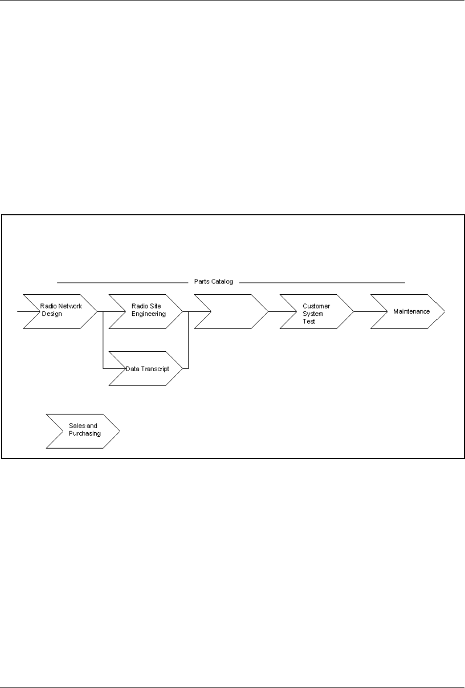
Appendix A
1 Introduction
This appendix provides an overview of the existing customer manuals for
RBS 884, the work procedures covered by the manuals, and the
recommended use of the manuals.
2 RBS 884 Customer Manuals
The customer manuals for RBS 884 cover the work procedures for Radio
Network Design, Radio Site Engineering, Data Transcript, Installation and
Test, Customer System Test, and Maintenance (see Figure A-1 on page
A-3).
RF Module Site Engineering
Manual
RBS Integration
Guidelines
Installation and
Maintenance Manual
Job Procedures
RBS Integration
Guidelines
Job Procedures
Installation and
Maintenance Manual
Job Procedures
Installation
and
Test
Figure A-1. RBS 884 Customer Manuals Related to Work Procedures
Use the RF Guidelines and Cell Design Data to plan and dimension a
cellular network based on the Ericsson Cellular Telephone System. Then
engineer all the sites using the Site Engineering Manual, and create a data
transcript using the RBS Integration Guidelines.
Install and test the sites using the Installation Manuals and the Job
Procedures. Commission the sites and test the cellular network using the
RBS Integration Guidelines and Job Procedures.
Use the Job Procedures during operation and maintenance from the MSC.
Use the Parts Catalog to identify replacable RBS parts, and use the
Installation Manuals for RBS hardware replacement and hardware
extensions.
5/1551-EN/LZB 119 3312 Uae Rev A 1997-11-20 A-3

Appendix A
Table A-1. RBS 884 Customer Manuals
Customer Manual Product Number
RF Guidelines and Cell Design Data for AS 100 EN/LZB 119 2614
RF Guidelines and Cell Design Data for AS 123 EN/LZB 119 2614/1
RBS 884 Series Site Engineering Manual EN/LZB 119 2855
RBS 884 Macro 800 MHz Installation and Maintenance
Manual EN/LZB 119 2170
RBS 884 Macro 1900 MHz Installation and Maintenance
Manual EN/LZB 119 2713
RBS 884 DBC Installation and Maintenance Manual EN/LZB 119 2856
RBS 884 Micro Installation and Maintenance Manual EN/LZB 119 2221
RBS 884 Compact Installation and Maintenance Manual EN/LZB 119 2224
RBS 884 Macro 800 MHz Parts Catalog EN/LZB 119 2453
RBS 884 Macro 1900 MHz Parts Catalog EN/LZB 119 2784
RBS 884 DBC Parts Catalog EN/LZB 119 2857
RBS 884 Micro Parts Catalog EN/LZB 119 2454
RBS 884 Compact Parts Catalog EN/LZB 119 2455
RBS 884 Integration Guidelines for AS 100 EN/LZB 119 2786
RBS 884 Integration Guidelines for AS 123 EN/LZB 119 2785
The Job Procedures are listed in the RBS 884 Integration Guidelines.
A-4 5/1551-EN/LZB 119 3312 Uae Rev A 1997-11-20

Appendix B
User Feedback
1 Introduction . ................. B-3
2 Ordering of Customer Manuals . ........ B-3
3 Problem Solving ................ B-3
4 Trouble Reporting . . . ............ B-3
6/1551-EN/LZB 119 3311 Uae Rev A 1997-11-20 B-1

Appendix B
B-2 6/1551-EN/LZB 119 3311 Uae Rev A 1997-11-20

Appendix B
1 Introduction
This appendix provides information on ordering and trouble reporting for
the RBS 884 customer manuals.
2 Ordering of Customer Manuals
For ordering of RBS 884 customer manuals, please contact your Ericsson
account manager.
3 Problem Solving
If you have any problems with a radio base station in the RBS 884 series
that can not be solved by reading the manuals, please contact your nearest
Ericsson Technical Assistance Center (TAC).
4 Trouble Reporting
Please report any errors found in this manual to:
Ericsson Radio Systems, AR/SO
S-164 80 Stockholm
Sweden
or
e-mail: erarimpl@memo.ericsson.se
send e-mail as “Mime Compliant” (7–bits)
6/1551-EN/LZB 119 3311 Uae Rev A 1997-11-20 B-3

Appendix B
B-4 6/1551-EN/LZB 119 3311 Uae Rev A 1997-11-20

Appendix C
Internal Cables
1 Introduction . ................. C-3
2 One-Sector Sites ................ C-3
3 Two-Sector Sites ................ C-5
4 Three-Sector Sites . . . ............ C-7
5 Transceivers (TRXs) . . ............ C-9
7/1551-EN/LZB 119 3311 Uae Rev PA4 1998-10-05 C-1

Appendix C
C-2 7/1551-EN/LZB 119 3311 Uae Rev PA4 1998-10-05
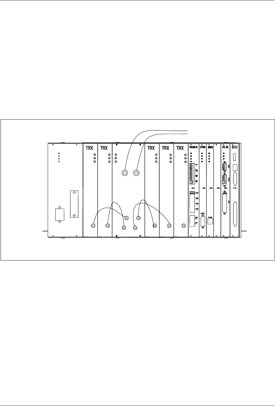
Appendix C
1 Introduction
This appendix describes the internal cabling within each RBS cabinet.
All internal cables are installed at the factory.
The configuration diagrams in this section show cabinets (main, and
primary), antenna configurations, and interconnections between cabinets.
The cabinets are shown with maximum equipment installed.
2 One-Sector Sites
Power
Error
Status
TX IN 1
TX IN 2
TX IN 3
TX IN 4
Power
Error
Status
Power
Error
Status
Power
Error
Status
Power
Error
Status
Power
Error
Status
Tx out Tx out Tx out Tx out Tx out
To antenna terminals
on I/O connector plate
Note: The TRX board in position 6 is used for DVER
Pos. 6
RX/TX
ANT 1 RX/TX
ANT 2
Figure C-1. One-Sector Site, One Cabinet, Two Antennas
7/1551-EN/LZB 119 3311 Uae Rev PA4 1998-10-05 C-3
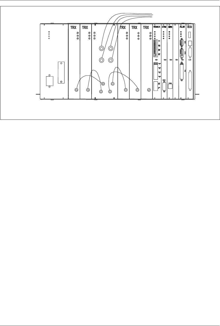
Appendix C
Note: The TRX board in position 6 is used for DVER
Power
Error
Status
Power
Error
Status
Power
Error
Status
Power
Error
Status
Power
Error
Status
Tx out Tx out Tx out Tx out Tx out
Power
Error
Status
TX IN 1
TX IN 2
TX IN 3
TX IN 4
Pos. 6
To antenna terminals
on I/O connector plate
RX/TX
ANT 1 RX/TX
ANT 2
RX/TX
ANT 3 RX/TX
ANT 4
Figure C-2. One-Sector Site, One Cabinet, Four Antennas
C-4 7/1551-EN/LZB 119 3311 Uae Rev PA4 1998-10-05
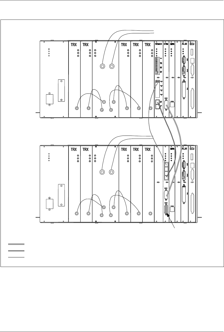
Appendix C
3 Two-Sector Sites
Note: The TRX board in position 6 is used for DVER
Power
Error
Status
TX IN 1
TX IN 2
TX IN 3
TX IN 4
Power
Error
Status
Power
Error
Status
Power
Error
Status
Power
Error
Status
Power
Error
Status
Tx out Tx out Tx out Tx out Tx out
To antenna terminals
on I/O connector plate
Power
Error
Status
TX IN 1
TX IN 2
TX IN 3
TX IN 4
Power
Error
Status
Power
Error
Status
Power
Error
Status
Power
Error
Status
Power
Error
Status
Tx out Tx out Tx out Tx out Tx out
Pos. 6
Pos. 6
Terminator
Main
Cabinet
Primary
Cabinet
EMRPB
AFS
TLINK
RX/TX
ANT 1 RX/TX
ANT 2
RX/TX
ANT 1 RX/TX
ANT 2
Figure C-3. Two-Sector Site, Two Cabinets, Main and Primary Cabinet have Two Antennas each
7/1551-EN/LZB 119 3311 Uae Rev PA4 1998-10-05 C-5
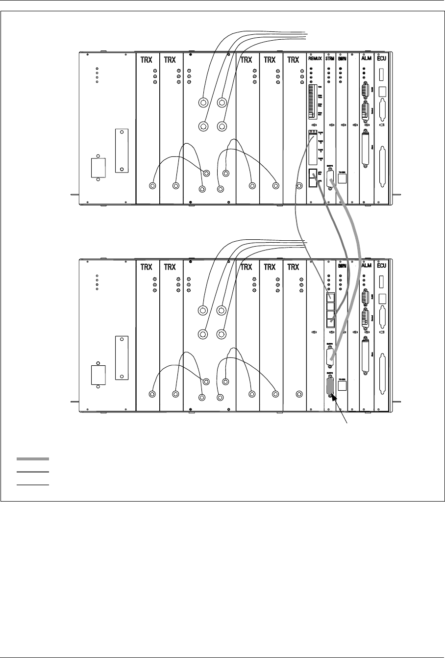
Appendix C
Note: The TRX board in position 6 is used for DVER
Power
Error
Status
Power
Error
Status
Power
Error
Status
Power
Error
Status
Power
Error
Status
Tx out Tx out Tx out Tx out Tx out
Power
Error
Status
TX IN 1
TX IN 2
TX IN 3
TX IN 4
To antenna terminals
on I/O connector plate
Pos. 6
Power
Error
Status
Tx out
Power
Error
Status
Power
Error
Status
Power
Error
Status
Power
Error
Status
Tx out Tx out Tx out Tx out
Power
Error
Status
TX IN 1
TX IN 2
TX IN 3
TX IN 4
Pos. 6
Terminator
EMRPB
AFS
TLINK
Main
Cabinet
Primary
Cabinet
RX/TX
ANT 1 RX/TX
ANT 2
RX/TX
ANT 3 RX/TX
ANT 4
RX/TX
ANT 1 RX/TX
ANT 2
RX/TX
ANT 3 RX/TX
ANT 4
Figure C-4. Two-Sector Site, Two Cabinets, Main and Primary Cabinet have Four Antennas each
C-6 7/1551-EN/LZB 119 3311 Uae Rev PA4 1998-10-05
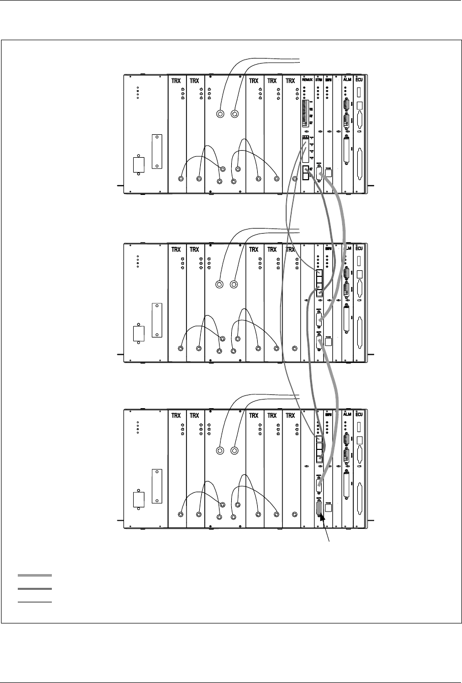
Appendix C
4 Three-Sector Sites
Note: The TRX board in position 6 is used for DVER
Main
Cabinet
Primary 1
Cabinet
Primary 2
Cabinet
Power
Error
Status
TX IN 1
TX IN 2
TX IN 3
TX IN 4
Power
Error
Status
Power
Error
Status
Power
Error
Status
Power
Error
Status
Power
Error
Status
Tx out Tx out Tx out Tx out Tx out
To antenna terminals
on I/O connector plate
Power
Error
Status
TX IN 1
TX IN 2
TX IN 3
TX IN 4
Power
Error
Status
Power
Error
Status
Power
Error
Status
Power
Error
Status
Power
Error
Status
Tx out Tx out Tx out Tx out Tx out
Power
Error
Status
TX IN 1
TX IN 2
TX IN 3
TX IN 4
Power
Error
Status
Power
Error
Status
Power
Error
Status
Power
Error
Status
Power
Error
Status
Tx out Tx out Tx out Tx out Tx out
Pos. 6
Pos. 6
Pos. 6
Terminator
EMRPB
AFS
TLINK
RX/TX
ANT 1 RX/TX
ANT 2
RX/TX
ANT 1 RX/TX
ANT 2
RX/TX
ANT 1 RX/TX
ANT 2
Figure C-5. Three-Sector Site, each Cabinet has Two Antennas
7/1551-EN/LZB 119 3311 Uae Rev PA4 1998-10-05 C-7
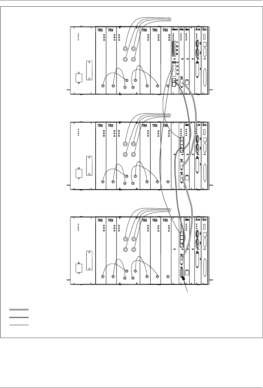
Appendix C
Note: The TRX board in position 6 is used for DVER
Main Cabinet
Primary 1
Cabinet
Primary 2
Cabinet
EMRPB
AFS
TLINK
Power
Error
Status
Power
Error
Status
Power
Error
Status
Power
Error
Status
Power
Error
Status
Tx out Tx out Tx out Tx out Tx out
Power
Error
Status
TX IN 1
TX IN 2
TX IN 3
TX IN 4
To antenna terminals
on I/O connector plate
Power
Error
Status
Tx out
Power
Error
Status
Power
Error
Status
Power
Error
Status
Power
Error
Status
Tx out Tx out Tx out Tx out
Power
Error
Status
TX IN 1
TX IN 2
TX IN 3
TX IN 4
Power
Error
Status
Tx out
Power
Error
Status
Power
Error
Status
Power
Error
Status
Power
Error
Status
Tx out Tx out Tx out Tx out
Power
Error
Status
TX IN 1
TX IN 2
TX IN 3
TX IN 4
Pos. 6
Pos. 6
Pos. 6
Terminator
RX/TX
ANT 1 RX/TX
ANT 2
RX/TX
ANT 3 RX/TX
ANT 4
RX/TX
ANT 1 RX/TX
ANT 2
RX/TX
ANT 3 RX/TX
ANT 4
RX/TX
ANT 1 RX/TX
ANT 2
RX/TX
ANT 3 RX/TX
ANT 4
Figure C-6. Three-Sector Site, each Cabinet has Four Antennas
C-8 7/1551-EN/LZB 119 3311 Uae Rev PA4 1998-10-05
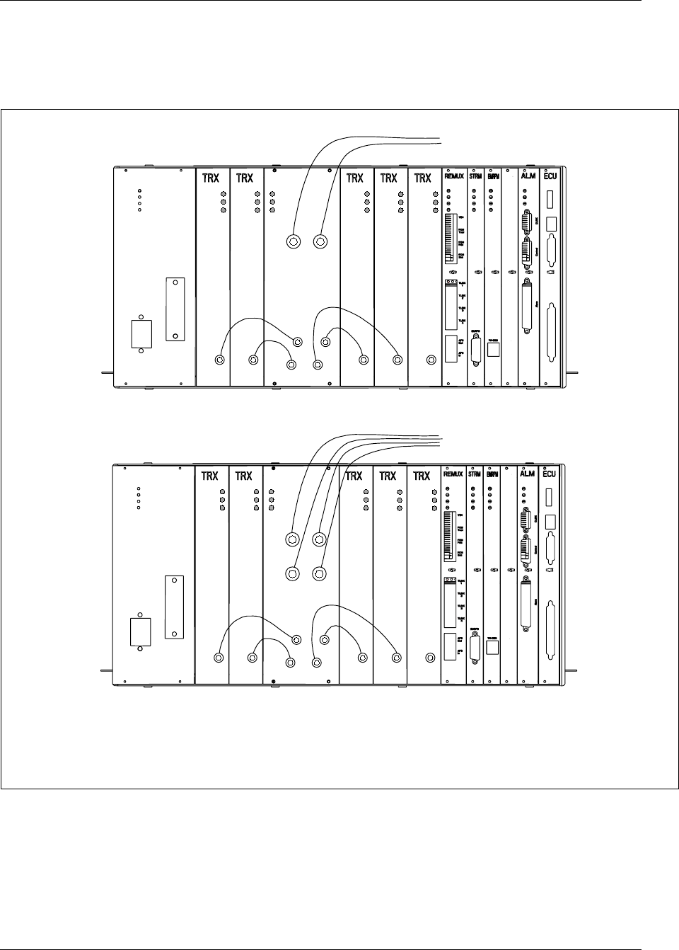
Appendix C
5 Transceivers (TRXs)
The transceiver cables RPM 513 977/00185 are installed as shown in
Figure C-7 on page C-9.
Note: The TRX board in position 6 is used for DVER
Cabinets illustrated are Main Cabinets, but the cabling is the same for Primary Cabinets.
Cabinet using Two Antennas
Cabinet using Four Antennas
Power
Error
Status
RX/TX
ANT 1 RX/TX
ANT 2
TX IN 1
TX IN 2
TX IN 3
TX IN 4
Power
Error
Status
Power
Error
Status
Power
Error
Status
Power
Error
Status
Power
Error
Status
Tx out Tx out Tx out Tx out Tx out
To antenna terminals
on I/O connector plate
Pos. 6
Power
Error
Status
Power
Error
Status
Power
Error
Status
Power
Error
Status
Power
Error
Status
Tx out Tx out Tx out Tx out Tx out
Power
Error
Status
RX/TX
ANT 1 RX/TX
ANT 2
TX IN 1
TX IN 2
TX IN 3
TX IN 4
RX/TX
ANT 3 RX/TX
ANT 4
To antenna terminals
on I/O connector plate
Pos. 6
Figure C-7. TRX Cable Connections for Main and Primary Cabinets
7/1551-EN/LZB 119 3311 Uae Rev PA4 1998-10-05 C-9

Appendix C
C-10 7/1551-EN/LZB 119 3311 Uae Rev PA4 1998-10-05

Appendix D
Conversion Table
1 Introduction . ................. D-3
2 Conversion Table ................ D-3
8/1551-EN/LZB 119 3312 Uae Rev A 1997-11-20 D-1

Appendix D
D-2 8/1551-EN/LZB 119 3312 Uae Rev A 1997-11-20

Appendix D
1 Introduction
This appendix contains a conversion table between some SI units and non
SI units.
2 Conversion Table
Table D-1. Conversion Table between SI Units and non SI Units
SI Unit Non SI Unit
1Nm 0.738 ft lbf (foot pound-force)
0.356 Nm 1 ft lbf
1kg 2.2 lb
0.45 kg 1 lb = 16 oz
0.305 m 1 ft = 12 inches
0.0254 1 inch
8/1551-EN/LZB 119 3312 Uae Rev A 1997-11-20 D-3