HARRIS M7200 M7200 700/800 MHz Mobile Radio User Manual TYPE CERTIFICATION REPORT
Harris Corporation M7200 700/800 MHz Mobile Radio TYPE CERTIFICATION REPORT
UserManual.wiki
>
HARRIS
>
M7200 User Manual
>
Manual 1
Contents
1.
manual 1
2.
manual 2
3.
Manual 1
4.
Manual 2
5.
Manual
6.
User Manual
Manual 1
Navigation menu
Upload a User Manual
Namespaces
Wiki Guide
HTML
PDF
Info
Views
User Manual
Discussion / Help
Navigation
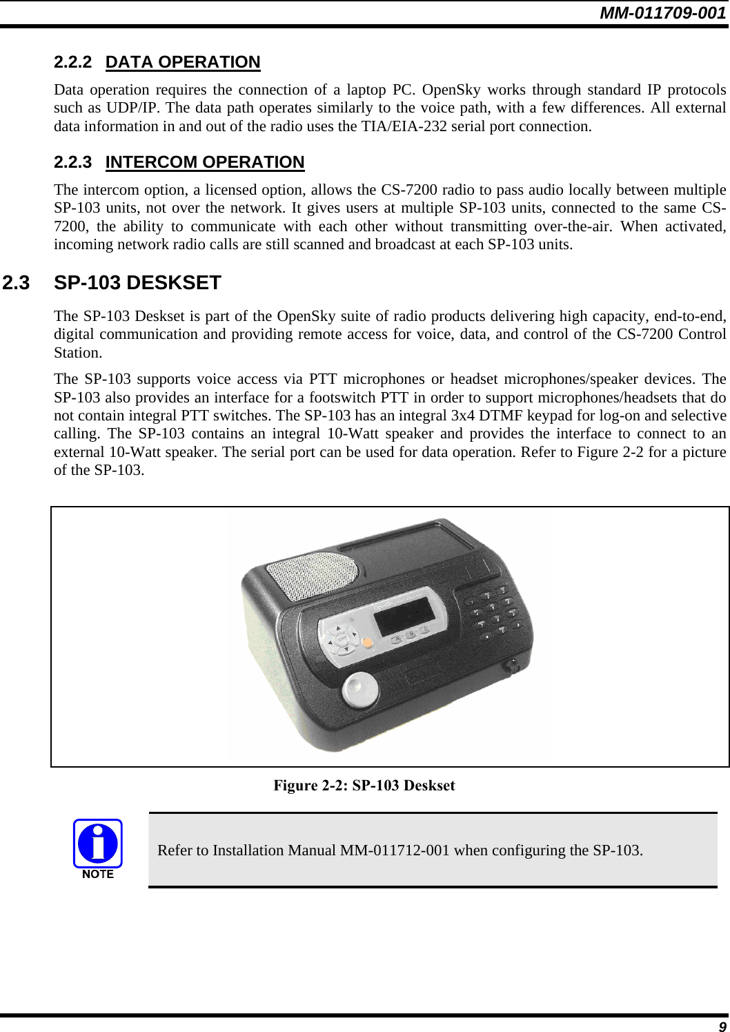
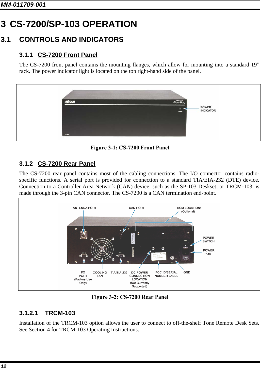
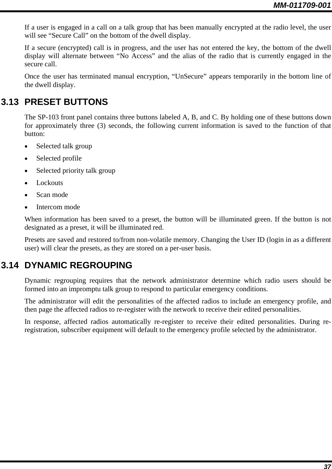
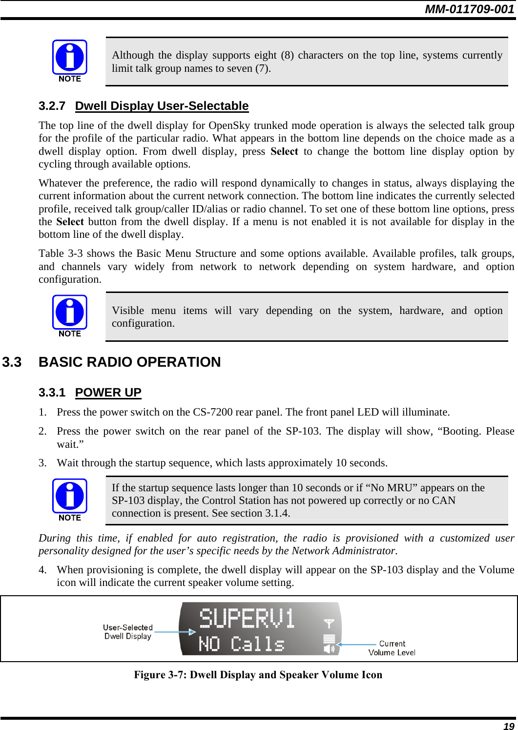
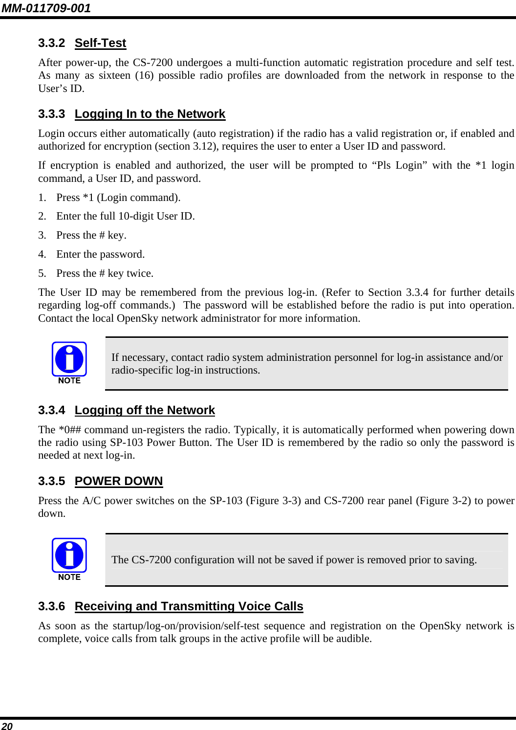
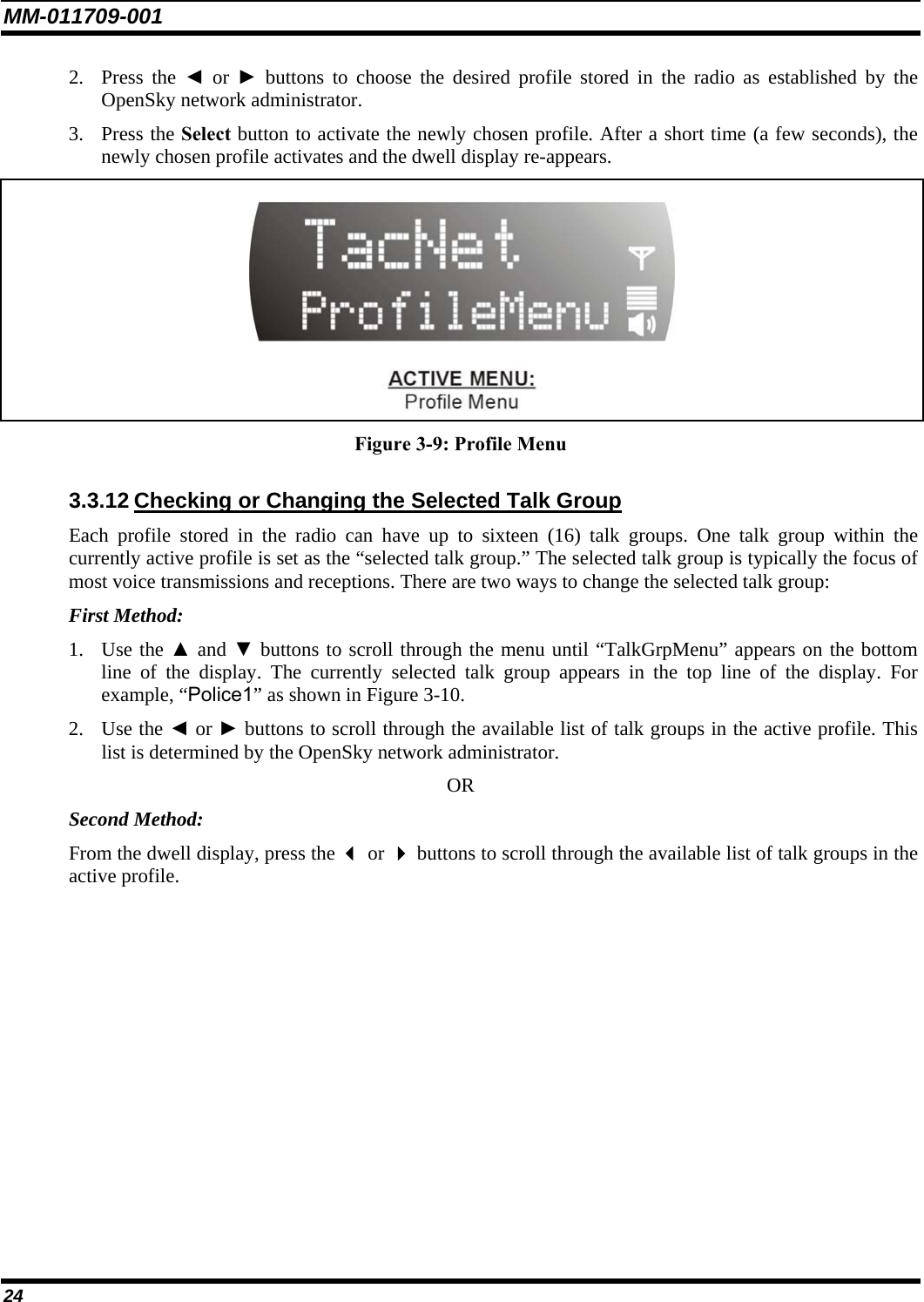
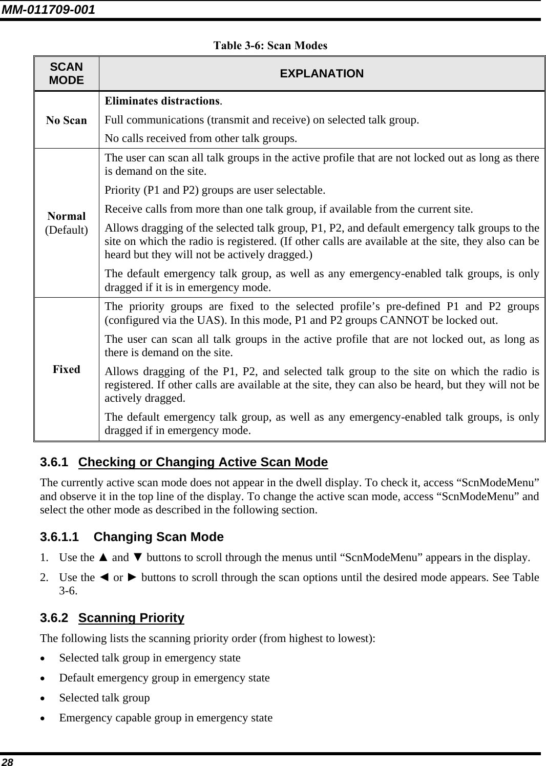
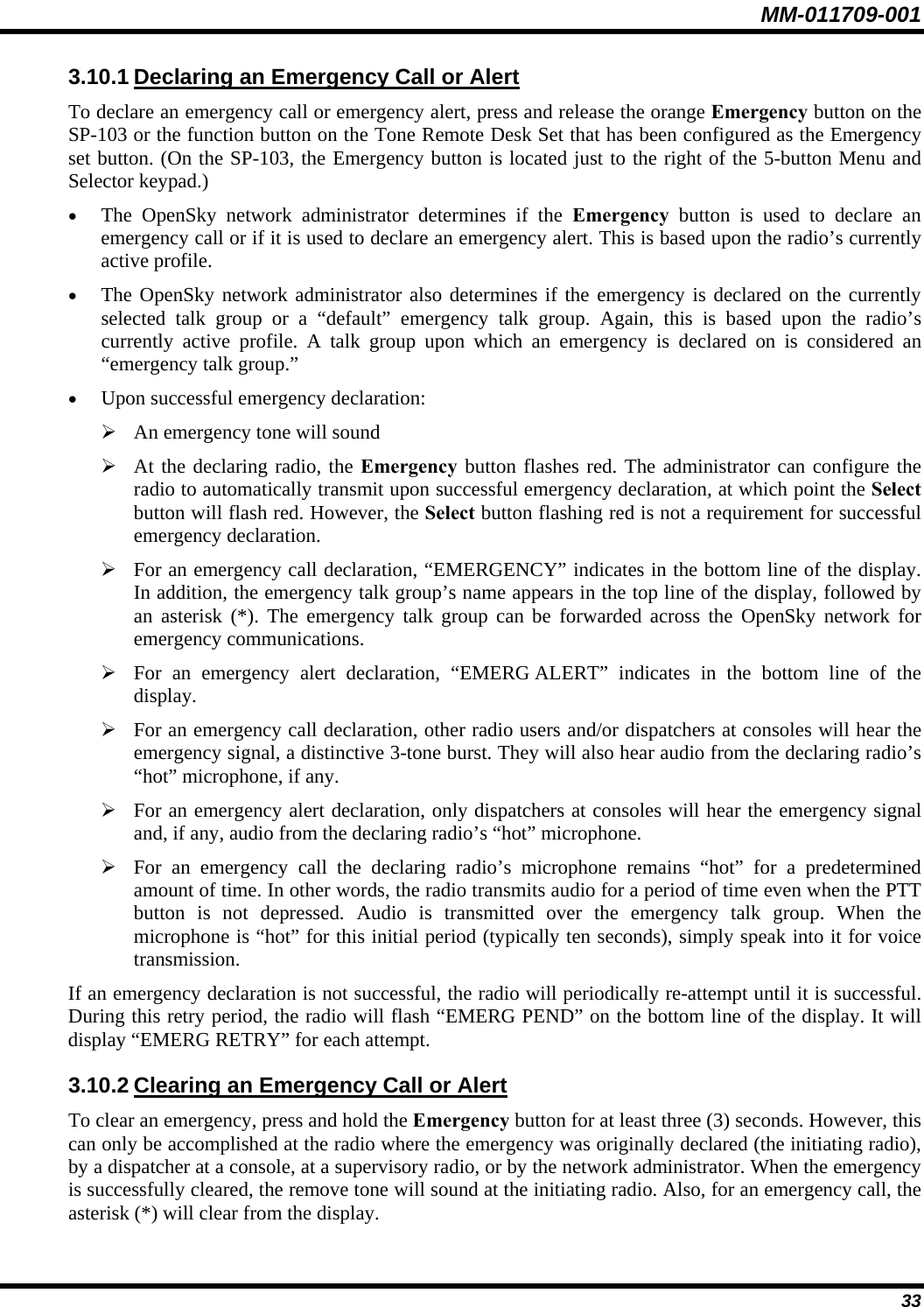
![MM-011709-001 16 Table 3-3: Basic Menu Structure Menu Name Radio Displays (first and second lines) Usage Notes To/From Dwell Display ▲ ▼ registration, RF sync and transceiver status codes Engineering Display (Menu may not be available per programming.) bit-error rates and RSSI data Displays radio system connection data. For engineering use. ▲ ▼ OFF/ON Silent Emergency “SilentEmerg” Use ◄ or ► to toggle between OFF/ON. Press Select to enable. ▲ ▼ available modes Operating Mode (e.g., OTP, OCF) “Mode Menu” Use ◄ or ► to turn choose an available mode. Press Select and confirm (Y/N) with ◄ or ► and Select again. ▲ ▼ current latitude and longitude (degrees:minutes:seconds) GPS Fix “GPS Fix” GPS latitude and longitude position of currently tuned-to base station [“GPS (Site)”] scrolls across top line of the display. ▲ ▼ User ID # of user currently logged in User ID “User ID” User’s identification/name scrolls across top line of the display (if programmed). ▲ ▼ Radio’s IP address IP Address “IP Address” Radio’s Internet Protocol (IP) address scrolls across top line of the display. ▲ ▼ station’s call sign Station Identification “Station ID” Station’s identification/name scrolls across top line of the display (if programmed). ▲ ▼ “OFF” Stealth Mode (display backlight is disabled) “StealthMenu” Use ◄ or ► to turn on. Press any button to turn it off. ▲ ▼ “LOW”, “MEDIUM”, “MEDHIGH”, “HIGH” Treble Level “Treble Menu” Use ◄ or ► to choose speaker treble level. Press Select to return to dwell display. ▲ ▼ “<< >>” Display Brightness “Bright Menu” Use ◄ or ► to brighten or dim backlighting. Press Select to return to dwell display. ▲ ▼ “OFF”, “LOW”, “MED”, HIGH” Side Tone Level “Side Menu” Use ◄ or ► to choose side tone level. Press Select to return to dwell display. ▲ ▼ See Next Page](https://usermanual.wiki/HARRIS/M7200.Manual-1/User-Guide-793273-Page-17.png)
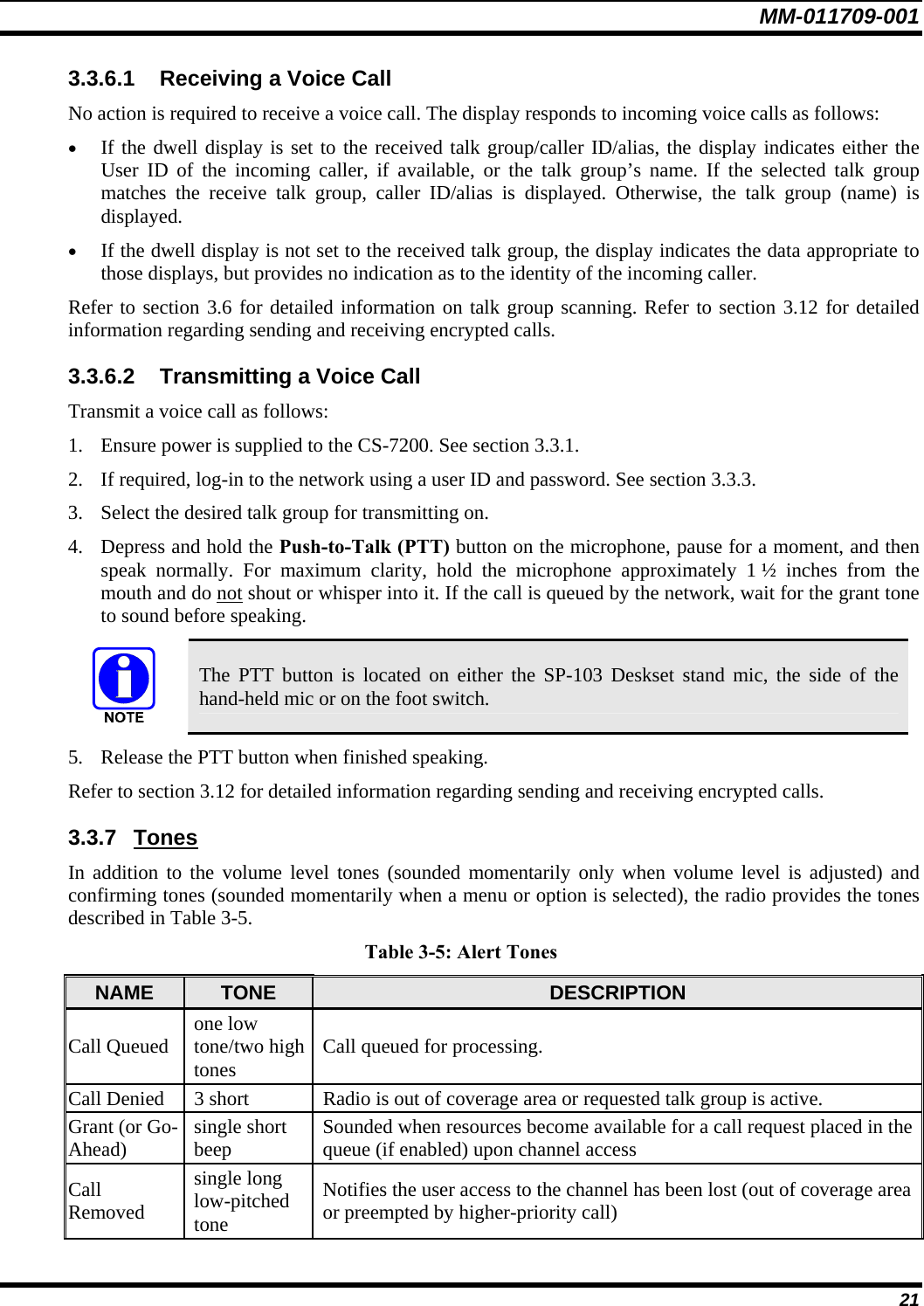
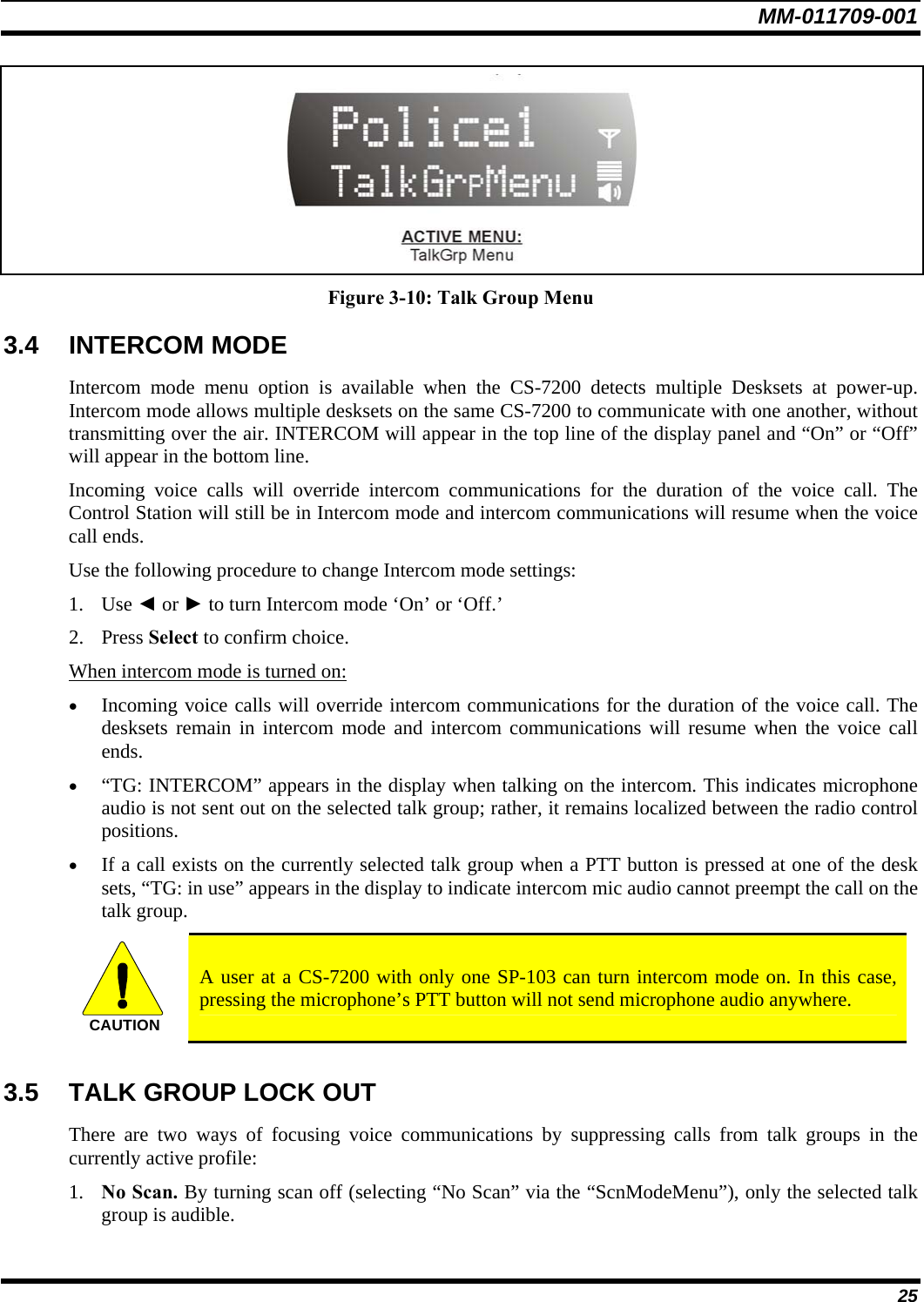
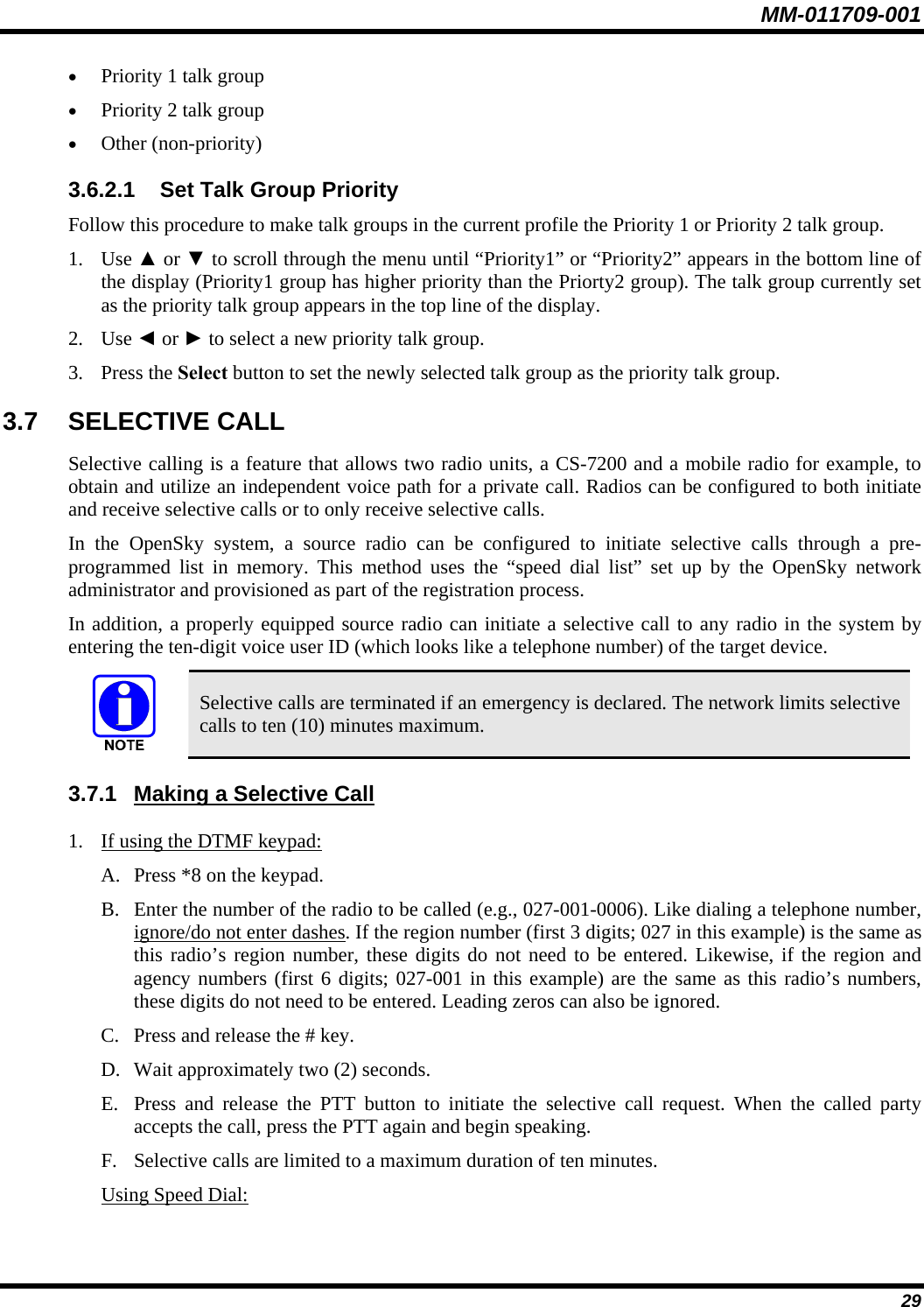
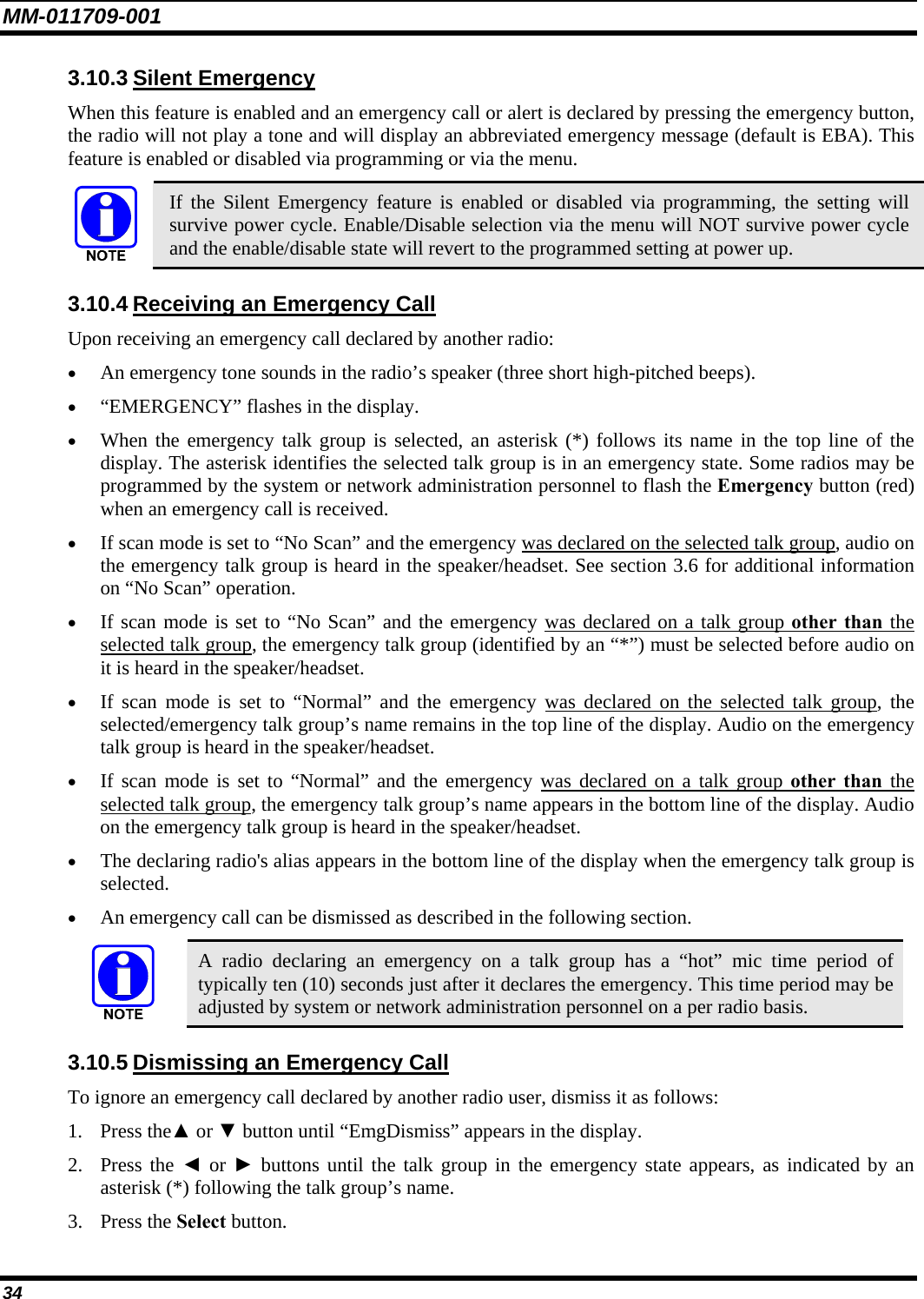
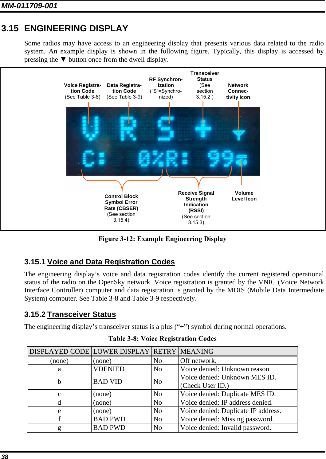
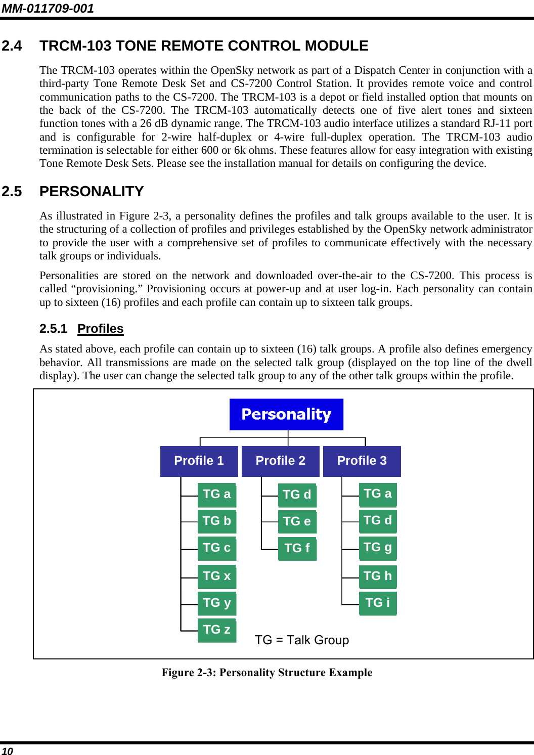
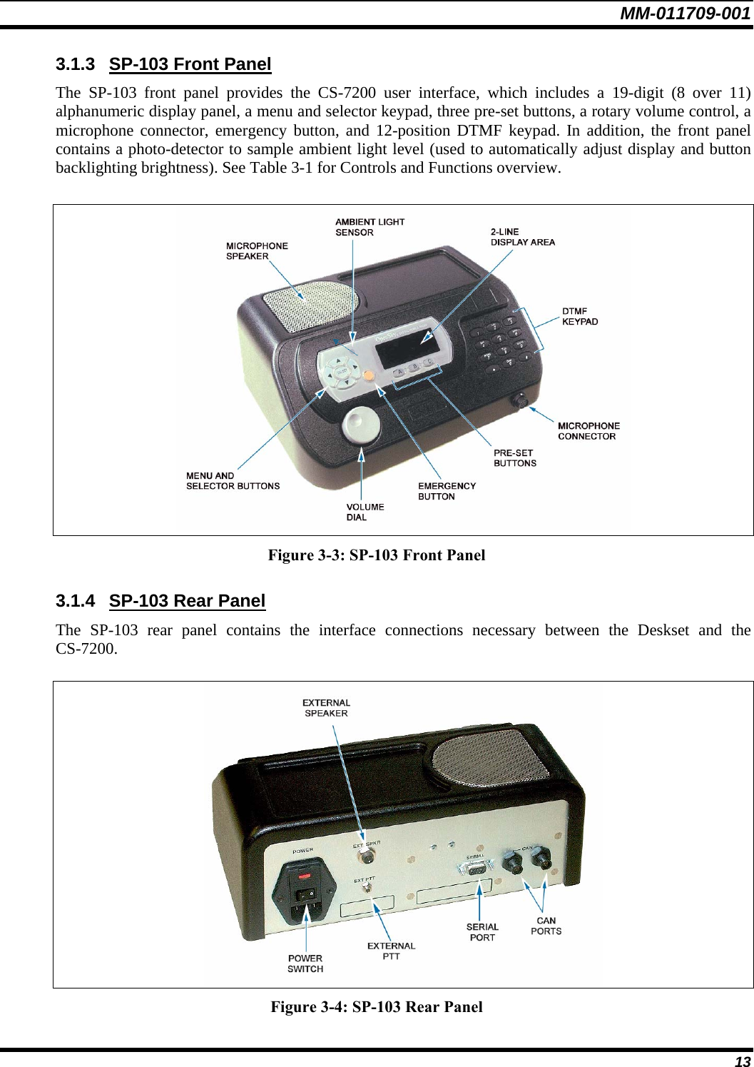
![MM-011709-001 35 3.11 DUAL-TONE MULTI-FREQUENCY KEYPAD Dual-Tone Multi-Frequency (DTMF) is the system used by touch-tone telephones. DTMF assigns a specific tone frequency to each key so a microprocessor can easily identify its activation. This allows for specific tasks such as entering a user ID and password, or selective calling. When a key on the DTMF keypad is pressed, a single low-pitched tone will be heard from the microphone. The key tones are not adjustable. To perform a command from the keypad, press the * key followed by one of the pre-set function keys as follows: *0 Log-off command: *0## (logs the user off the system). See page 20 for additional information. *1 Log-in command: *1<User ID> # <Password> ## (required for encryption). See page 20 for additional information. *5 Single Site Channel command: *5<SMR/NPSPAC channel># *6 Load Default Personality command: *6#. This command applies only if the radio is not voice-registered on the network. *7 Initiate Selective Alert command: *7<Target ID>#[Choose Message]#. See page 30 for additional information. *8 Radio-to-Radio Call command: Selective call number # (PTT to dial). See page 29 for additional information. *9 Public Switched Telephone Network (PSTN) Call command: See page 32 for additional information. *32 Begin Manual Encryption command: *32<Pre-Determined Encryption Key># 1 – 16 digit encryption key for 128 bit encryption; 17 – 32 digit encryption key for 256 bit encryption. See page 36 for additional information. *33 End Manual Encryption command: *33#. 3.11.1 Password Entry Password characters are encrypted on the display using symbols to indicate the entry. The encryption symbols for each entry will appear in the display as they are scrolled through, for example: '-' and '+'. Press the # key twice to complete the entry process. If the password is wrong, the radio will not successfully register with the network for wide area voice reception. The radio can still be used in single-site mode. 3.11.2 Overdial In order to send DTMF tones over the radio link, hold the PTT key when pressing the DTMF keys. 3.12 ENCRYPTION In the OpenSky network, both data and voice use a 128-bit or 256-bit key encryption standard published by the Federal Information Processing Service (FIPS), called Advanced Encryption Standard (AES). AES is approved by the U.S. Department of Commerce for encryption of classified materials. When encryption is enabled on the network, data is encrypted from the MDIS to the Mobile End System (MES). This form of encryption provides air-link security.](https://usermanual.wiki/HARRIS/M7200.Manual-1/User-Guide-793273-Page-36.png)