HARRIS M7200 M7200 700/800 MHz Mobile Radio User Manual manual 2
Harris Corporation M7200 700/800 MHz Mobile Radio manual 2
UserManual.wiki
>
HARRIS
>
M7200 User Manual
>
manual 2
Contents
1.
manual 1
2.
manual 2
3.
Manual 1
4.
Manual 2
5.
Manual
6.
User Manual
manual 2
Navigation menu
Upload a User Manual
Namespaces
Wiki Guide
HTML
PDF
Info
Views
User Manual
Discussion / Help
Navigation
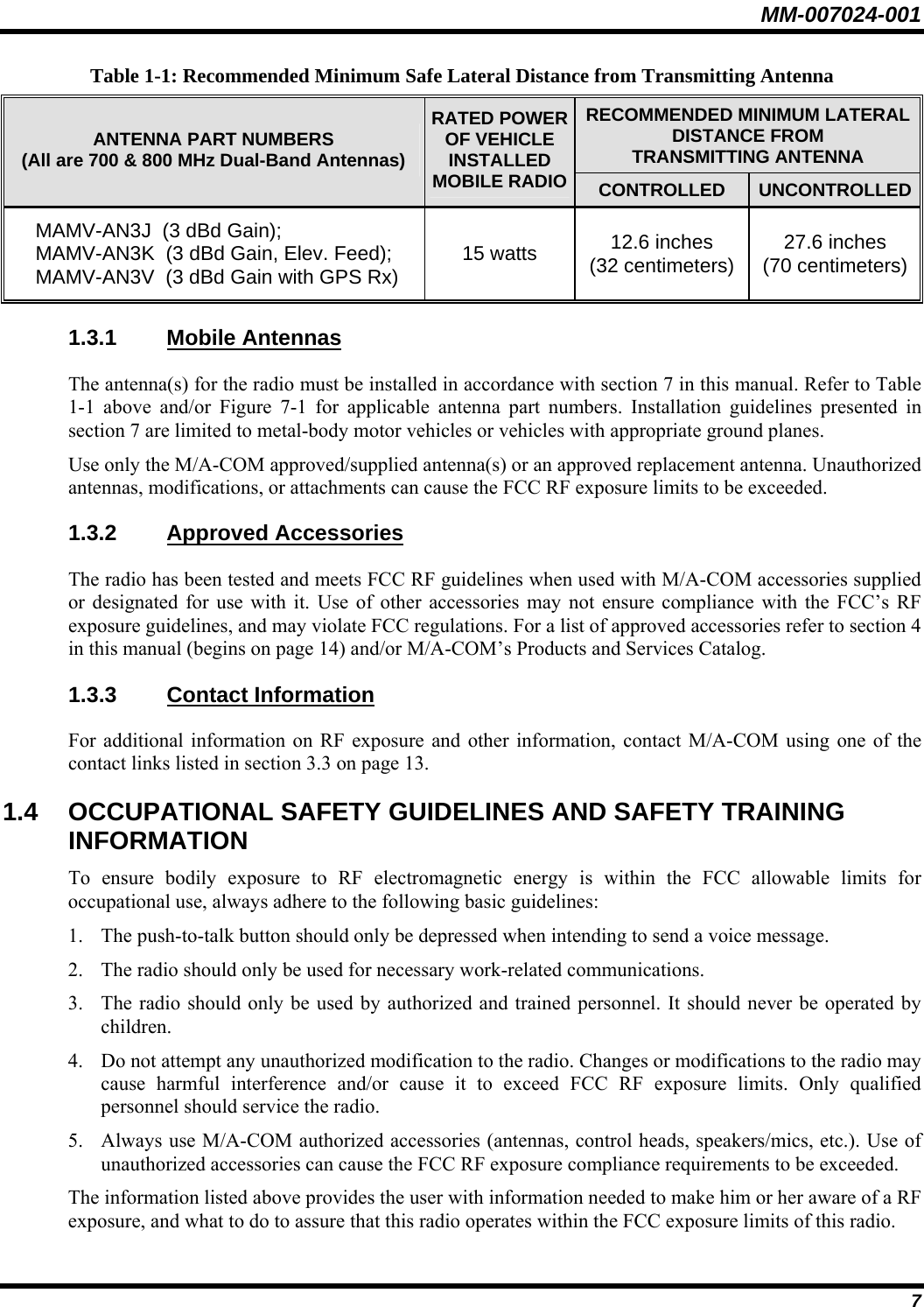
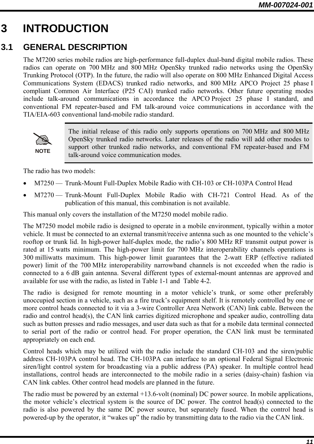
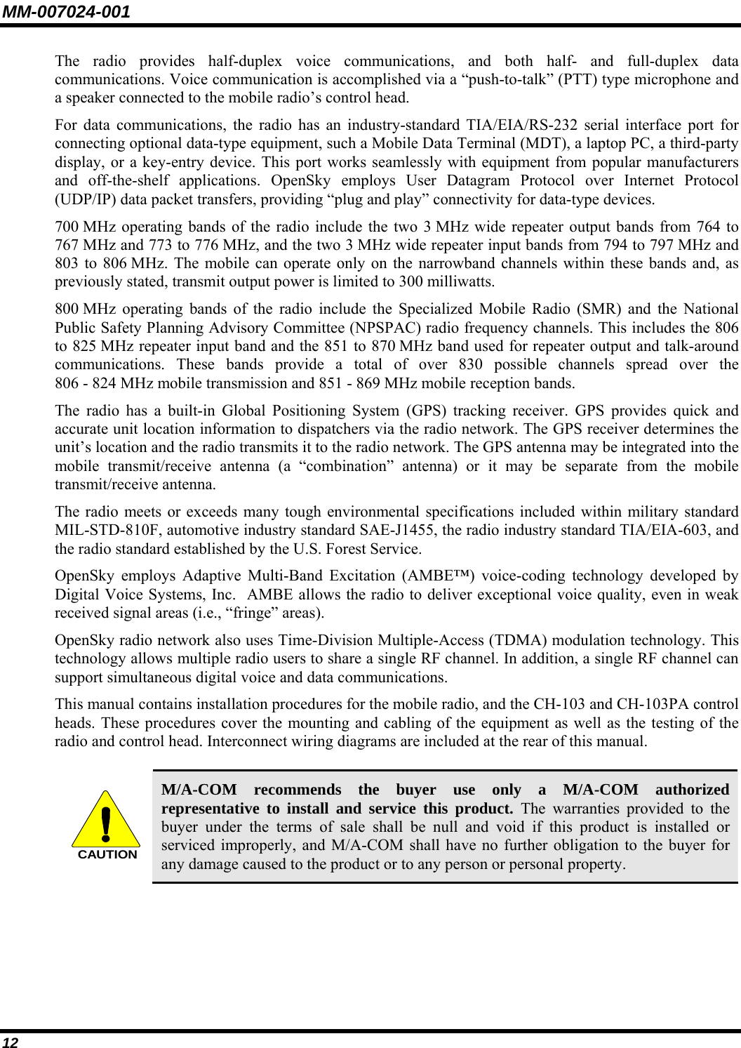
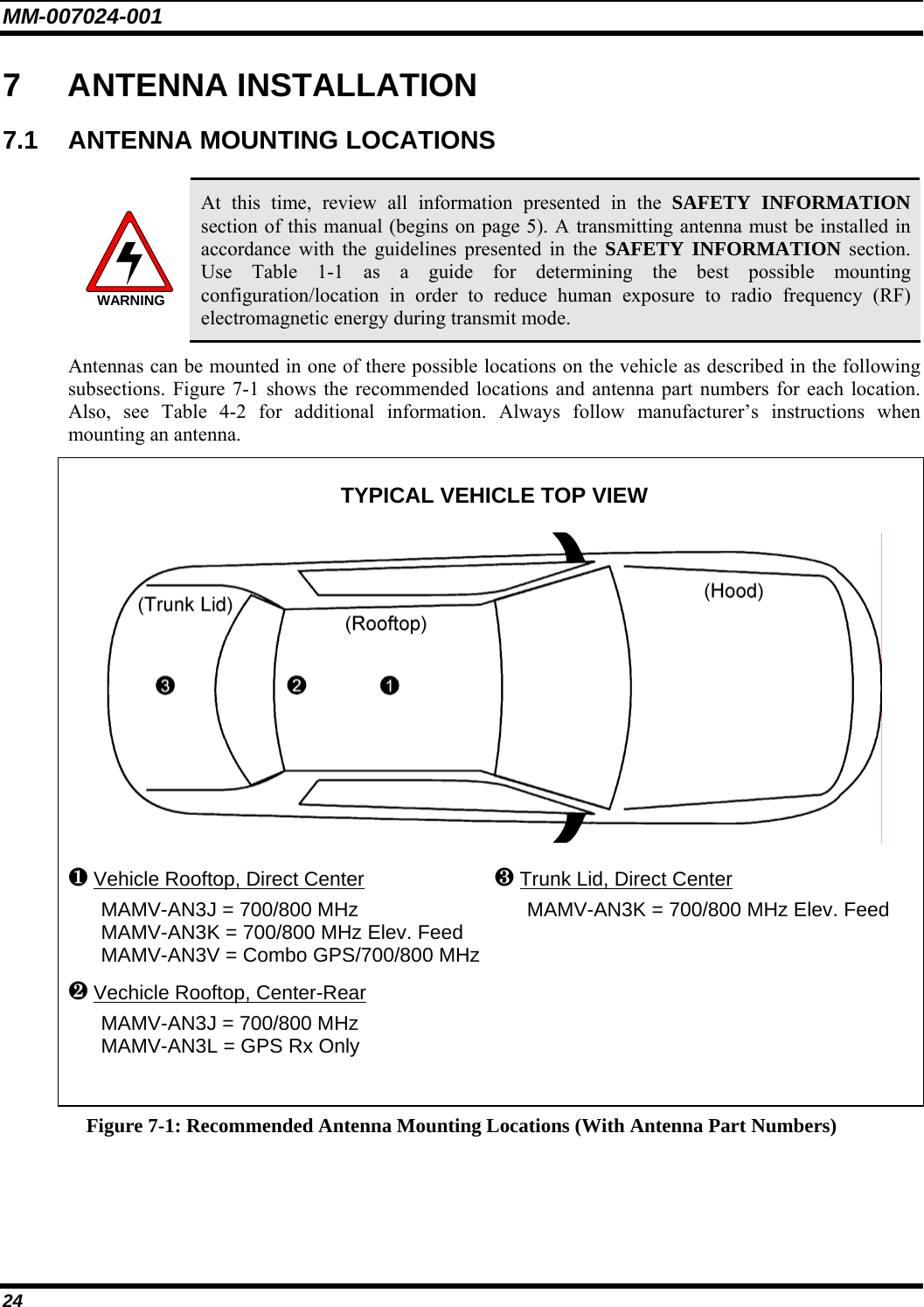
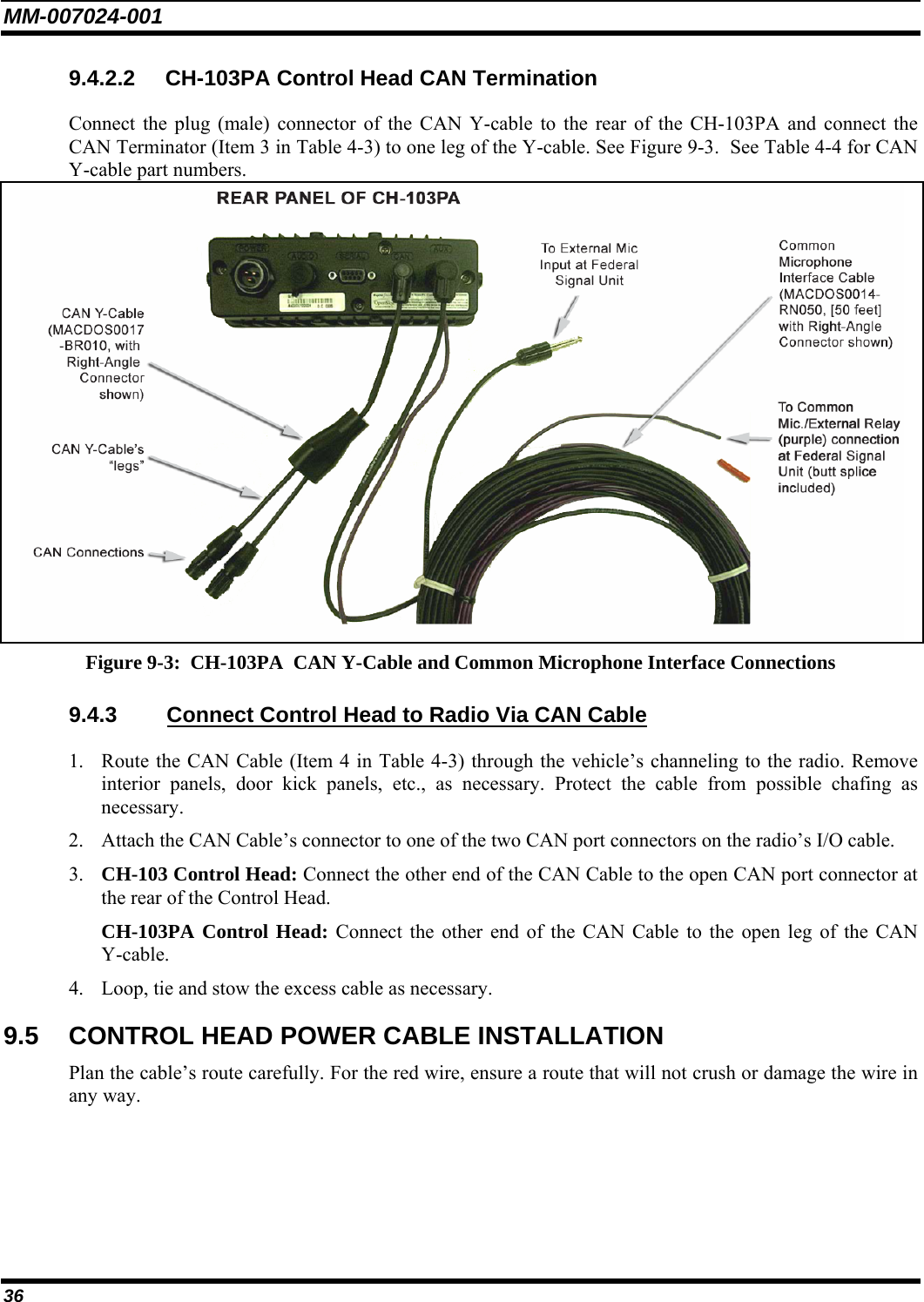
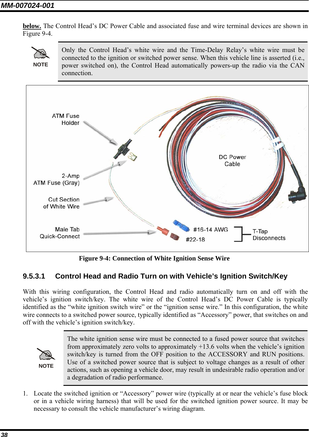
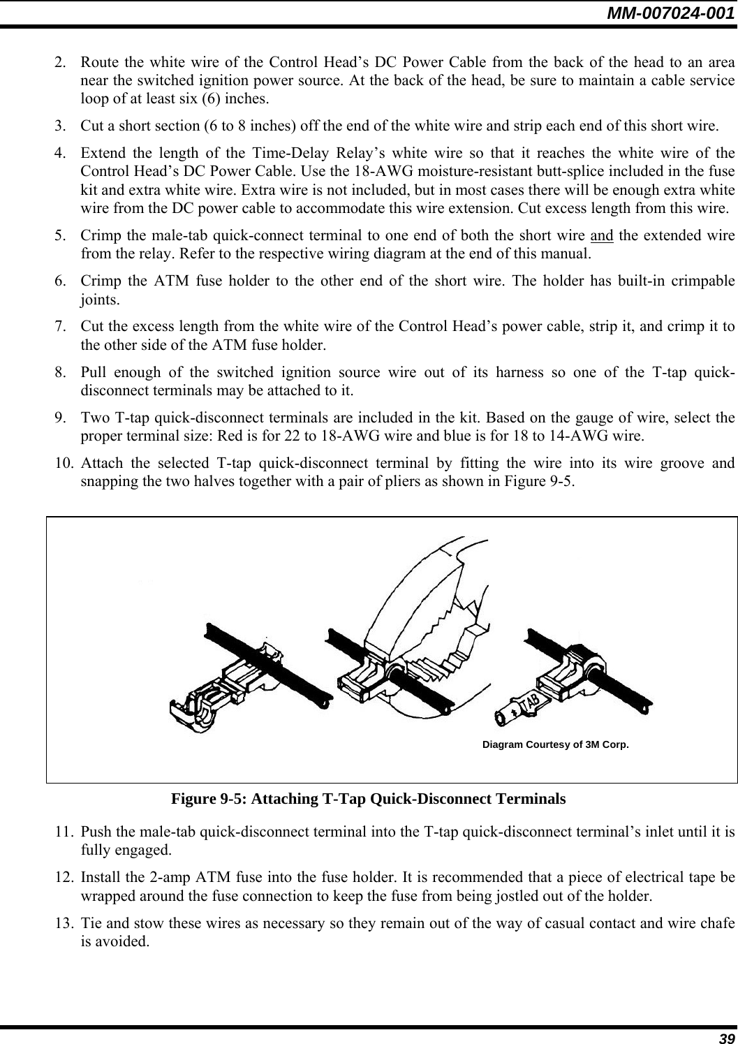
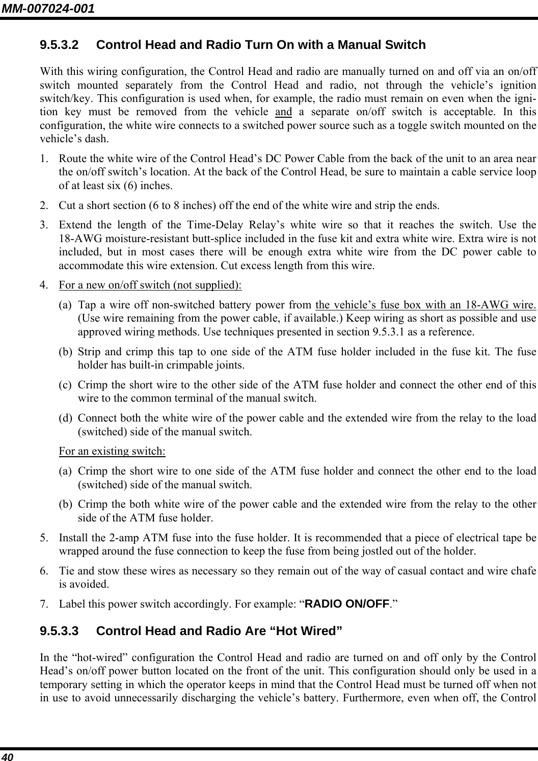

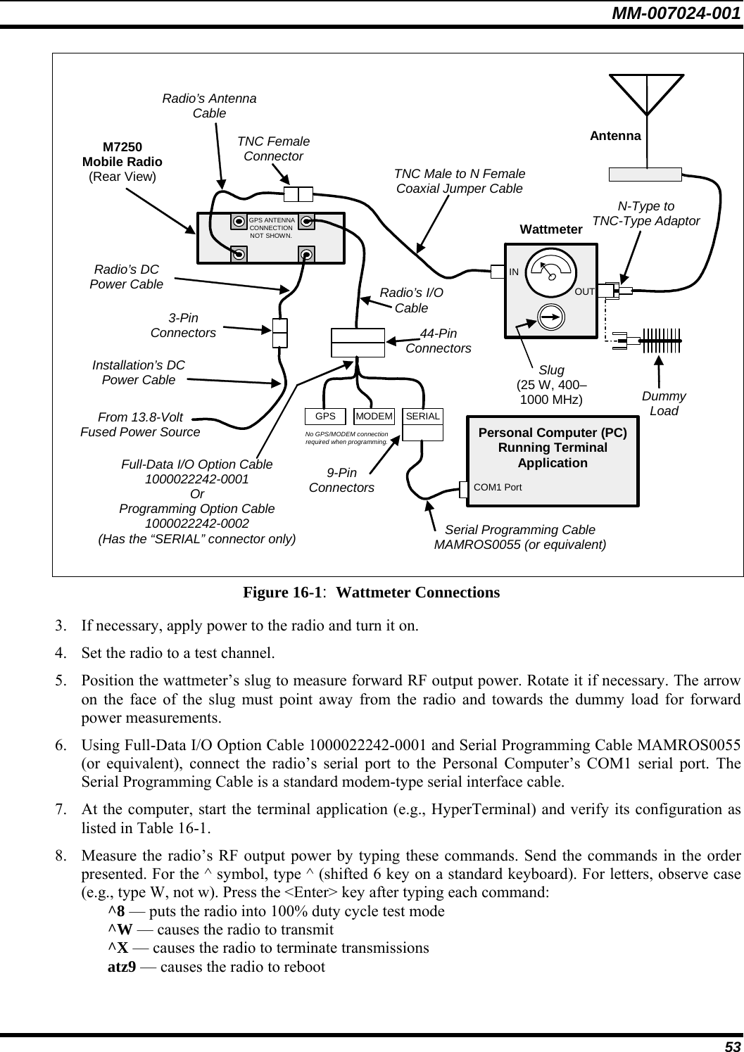
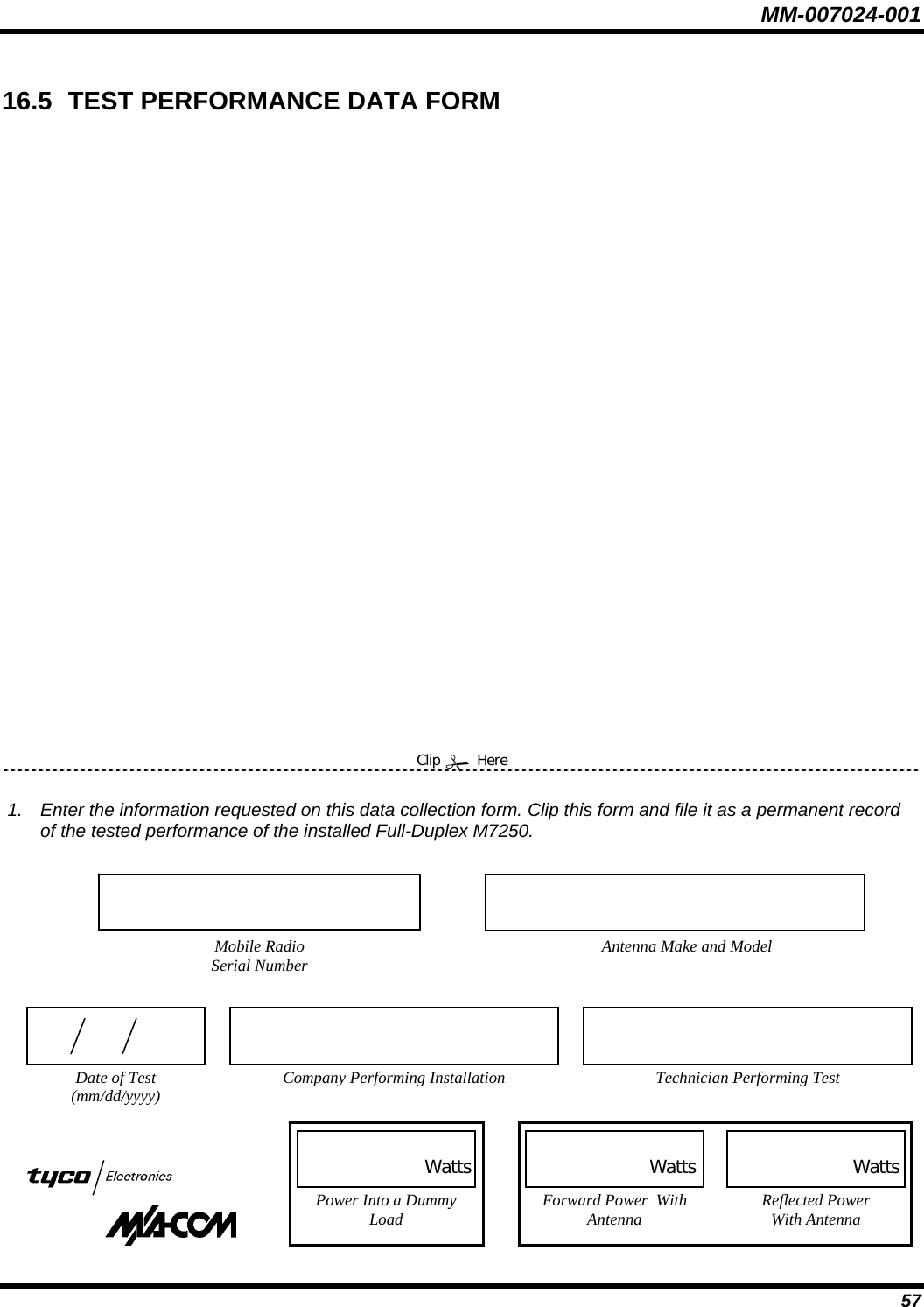
![MM-007024-001 52 16.2 REQUIRED TEST EQUIPMENT Table 16-1: Required Test Equipment TEST EQUIPMENT COMMENTS PC or Laptop PC • With Microsoft Windows® 95 (or greater) operating system and a termi-nal application to issue commands through the COM1 serial port (such as HyperTerminal). Recommended HyperTerminal Settings: General (tab): Settings (tab): Connect Using: COM1 Terminal Keys (selected) Configure (button) Emulation = VT100 Bits Per Second = 19200 Backscroll Buffer Line = 500 Data Bits = 8 ASCII Setup (button) Parity = None Everything unchecked Stop Bits = 1 Line Delay & Character = 0 Flow Control = None Terminal Settings (button) 132 Column Mode = unchecked Character Set = ASCII TIA/EIA-232 Serial Cable • With 9-pin D-Subminiature Male-Female Connectors, 1:1, shielded (Option MAMROS0055 or equivalent) Wattmeter • Bird Electronic Corporation Model 43 or equivalent, with N-type female connectors on both the input and output sides. As an alternative to using a wattmeter, a Voltage Standing Wave Ratio (VSWR) meter, Bird Electronic Corporation Model 4391A or equivalent can be used to carry out the required RF (Radio Frequency) power testing. Wattmeter Slug For use with the wattmeter; rated power of 25 watts and frequency range appropriate to the 800 MHz output of the mobile radio [Bird Electronics Element 25E (25 watts, 400–1000 MHz) or equivalent]. Coaxial Jumper Cable • 50 Ohm Coaxial Cable with TNC-type male connector on one end and N-type male connector on the other end, approximately three feet in length (Pasternack Enterprises PE3661-36 or equivalent). This cable must have VSWR below 1.5:1 at 800 MHz. N-Type to TNC Adapter N-type male to TNC-type female (Pasternack Enterprises PE9090 or equivalent). Dummy Load RF terminator rated at 50-ohm resistance and greater than 50 watts power, with N-type male connector (Pasternack Enterprises PE6106 or equivalent). Vehicle-Mounted Antenna Tests are performed with the vehicle-mounted antenna per the installation described in Section 7 of this manual. 16.3 TESTING WITH A DUMMY LOAD Figure 16-1 shows basic interconnections required for the following test procedure. 1. Using the N-type male to TNC-type male coaxial jumper cable, connect the radio’s antenna connector to the wattmeter’s input. 2. Connect the dummy load to the wattmeter’s output (in place of the antenna cable and the antenna).](https://usermanual.wiki/HARRIS/M7200.manual-2/User-Guide-588517-Page-52.png)