HARRIS M7200 M7200 700/800 MHz Mobile Radio User Manual manual 2
Harris Corporation M7200 700/800 MHz Mobile Radio manual 2
HARRIS >
Contents
manual 2

Installation Manual
MM-007024-001
Sep-05
M7200 Series Mobile Radio
Trunk-Mount Full-Duplex
Mobile Radio with Control Head
for OpenSky Radio Networks

MM-007024-001
2
MANUAL REVISION HISTORY
REVISION DATE REASON FOR CHANGE
— September 2005 Initial release.
M/A-COM Technical Publications would particularly appreciate feedback on any errors found in this document and
suggestions on how the document could be improved. Submit your comments and suggestions to:
Wireless Systems Business Unit
M/A-COM, Inc. or fax your comments to: (434) 455-6851
Technical Publications
221 Jefferson Ridge Parkway or e-mail us at: techpubs@tycoelectronics.com
Lynchburg, VA 24501
CREDITS
M/A-COM, OpenSky and EDACS are registered trademarks of M/A-COM, Inc.
Microsoft and Windows are registered trademarks of Microsoft Corporation.
All other brand and product names are trademarks, registered trademarks, or service marks of their respective holders.
NOTICE
This device is made under license under one or more of the following U.S. Patents: 4,590,473; 4,636,791; 5,148,482;
5,185,796; 5,271,017; 5,377,229; 4,716,407; 4,972,460; 5,502,767; 5,146,497; 5,164,986; 5,185,795.
The voice coding technology embodied in this product is protected by intellectual property rights including patent rights,
copyrights, and trade secrets of Digital Voice Systems, Inc. The user of this technology is explicitly prohibited from
attempting to decompile, reverse engineer, or disassemble the Object Code, or in any other way convert the Object Code into
human-readable form.
This manual covers M/A-COM products manufactured and sold by M/A-COM, Inc.
Repairs to this equipment should be made only by an authorized service technician or facility designated by the supplier. Any
repairs, alterations or substitution of recommended parts made by the user to this equipment not approved by the
manufacturer could void the user’s authority to operate the equipment in addition to the manufacturer’s warranty.
The software contained in this device is copyrighted by M/A-COM, Inc. Unpublished rights are reserved under the copyright
laws of the United States.
This manual is published by M/A-COM, Inc. without any warranty. Improvements and changes to this manual necessitated by typographical errors,
inaccuracies of current information, or improvements to programs and/or equipment, may be made by M/A-COM, Inc., at any time and without notice. Such
changes will be incorporated into new editions of this manual. No part of this manual may be reproduced or transmitted in any form or by any means,
electronic or mechanical, including photocopying and recording, for any purpose, without the express written permission of M/A-COM, Inc.
Copyright© 2005, M/A-COM, Inc. All rights reserved.

MM-007024-001
3
TABLE OF CONTENTS Page
1 SAFETY INFORMATION .......................................................................................................... 5
1.1 SYMBOLS USED IN THIS MANUAL................................................................................... 5
1.2 RF ENERGY EXPOSURE AWARENESS AND CONTROL INFORMATION FOR FCC
OCCUPATIONAL USE REQUIREMENTS ................................................................... 5
1.2.1 Federal Communications Commission Regulations ..................................................................6
1.3 COMPLIANCE WITH RF EXPOSURE STANDARDS......................................................... 6
1.3.1 Mobile Antennas ........................................................................................................................7
1.3.2 Approved Accessories ................................................................................................................7
1.3.3 Contact Information...................................................................................................................7
1.4 OCCUPATIONAL SAFETY GUIDELINES AND SAFETY TRAINING INFORMATION....... 7
1.5 COMMON HAZARDS ......................................................................................................... 8
2 SPECIFICATIONS..................................................................................................................... 9
2.1 GENERAL ........................................................................................................................... 9
2.2 TRANSCEIVER................................................................................................................... 9
2.3 REGULATORY ................................................................................................................. 10
3 INTRODUCTION .....................................................................................................................11
3.1 GENERAL DESCRIPTION................................................................................................ 11
3.2 RELATED DOCUMENTS.................................................................................................. 13
3.3 CONTACTING M/A-COM FOR TECHNICAL ASSISTANCE............................................ 13
4 UNPACKING AND CHECKING EQUIPMENT........................................................................14
4.1 MATERIALS......................................................................................................................14
4.2 MATERIAL INSPECTION ................................................................................................. 17
5 PLANNING THE INSTALLATION........................................................................................... 18
5.1 GENERAL INFORMATION............................................................................................... 18
5.2 TOOLS REQUIRED .......................................................................................................... 18
5.3 LOCATING COMPONENTS ............................................................................................. 20
6 MOUNTING THE MOBILE RADIO IN THE TRUNK............................................................... 21
6.1 BRACKET INSTALLATION............................................................................................... 21
6.2 MOUNT THE RADIO INTO THE BRACKET ..................................................................... 23
7 ANTENNA INSTALLATION.................................................................................................... 24
7.1 ANTENNA MOUNTING LOCATIONS............................................................................... 24
7.1.1 Direct Center or Center-Rear of Rooftop.................................................................................25
7.1.2 Center of Trunk Lid..................................................................................................................25
7.2 ANTENNA INSTALLATION PROCEDURE....................................................................... 25
7.2.1 Install and Connect Mobile Radio Antenna .............................................................................25
7.2.2 Install and Connect GPS Antenna............................................................................................26
8 RADIO DC POWER INSTALLATION.....................................................................................27
8.1 ON/OFF POWER WIRING CONFIGURATIONS .............................................................. 27
8.2 POWER INSTALLATION PROCEDURE .......................................................................... 28
8.2.1 Install Main Fuse Holder, Time-Delay Relay, and Fuse Block................................................28
8.2.2 Make Ground Connections at Fuse Block and Time-Delay Relay...........................................30
8.2.3 Complete Fuse Block and DC Power Cable Connections .......................................................31

MM-007024-001
4
TABLE OF CONTENTS Page
9 CONTROL HEAD INSTALLATION.........................................................................................33
9.1 GENERAL INFORMATION............................................................................................... 33
9.2 BRACKET INSTALLATION...............................................................................................34
9.2.1 Standard U-Shaped Bracket.....................................................................................................34
9.2.2 Mounting Pedestal (Optional)..................................................................................................34
9.3 ATTACH CONTROL HEAD TO BRACKET.......................................................................34
9.4 CAN CONNECTIONS .......................................................................................................35
9.4.1 General Information.................................................................................................................35
9.4.2 Make CAN Termination............................................................................................................35
9.4.3 Connect Control Head to Radio Via CAN Cable .....................................................................36
9.5 CONTROL HEAD POWER CABLE INSTALLATION ........................................................36
9.5.1 Install Fuse Holder and DC Power Cable and Make Power Connection................................37
9.5.2 Make Ground Connection ........................................................................................................37
9.5.3 Connect DC Power Cable’s White Wire ..................................................................................37
10 DATA-ONLY RADIO CONNECTIONS ...................................................................................42
11 MICROPHONE INSTALLATION.............................................................................................43
11.1 CH-103 AND CH-103PA CONNECTIONS........................................................................43
11.2 COMMON MICROPHONE INTERFACE CONNECTIONS (CH-103PA ONLY)................43
12 SPEAKER INSTALLATION ....................................................................................................44
13 OPTIONAL CABLES............................................................................................................... 45
13.1 FULL-DATA I/O OPTION CABLE...................................................................................... 45
13.2 PROGRAMMING OPTION CABLE................................................................................... 46
14 GPS NMEA-FORMATTED SERIAL DATA CONNECTION ...................................................48
15 INITIAL POWER-UP TEST .....................................................................................................49
16 PERFORMANCE TESTS ........................................................................................................50
16.1 CHANGING OPERATING MODE FOR TESTS ................................................................51
16.2 REQUIRED TEST EQUIPMENT.......................................................................................52
16.3 TESTING WITH A DUMMY LOAD ....................................................................................52
16.4 TESTING WITH THE ANTENNA.......................................................................................54
16.5 TEST PERFORMANCE DATA FORM ..............................................................................57
17 COMPLETE THE INSTALLATION .........................................................................................59
18 WARRANTY ............................................................................................................................60
19 WIRING DIAGRAM: MOBILE RADIO & CH-103 CONTROL HEAD ....................................61
20 WIRING DIAGRAM: MOBILE RADIO & CH-103PA CONTROL HEAD ...............................63
(Continued)
MM-007024-001
5
1 SAFETY INFORMATION
1.1 SYMBOLS USED IN THIS MANUAL
The following symbols are used throughout this manual:
WARNING
The WARNING symbol calls attention to a procedure, practice, or the like, which, if
not correctly performed or adhered to, could result in personal injury. Do not proceed
beyond a WARNING symbol until the conditions identified are fully understood or met.
CAUTION
The CAUTION symbol calls attention to an operating procedure, practice, or the like,
which, if not performed correctly or adhered to, could result in damage to the
equipment or severely degrade equipment performance.
NOTE
The NOTE symbol calls attention to supplemental information, which may improve
system performance or clarify a process or procedure.
1.2 RF ENERGY EXPOSURE AWARENESS AND CONTROL
INFORMATION FOR FCC OCCUPATIONAL USE REQUIREMENTS
Before using the mobile two-way radio, read this important RF energy awareness and control
information and operational instructions to ensure compliance with RF exposure guidelines.
NOTE
This radio is intended for use in occupational/controlled conditions, where users have
full knowledge of their exposure and can exercise control over their exposure to remain
below RF exposure limits. This radio is NOT authorized for general population,
consumer, or any other use.
CAUTION
Changes or modifications not expressly approved by M/A-COM, Inc. could void the
user's authority to operate the equipment.
This two-way radio uses electromagnetic energy in the radio frequency (RF) spectrum to provide
communications between two or more users over a distance. It uses RF energy or radio waves to send and
receive calls. RF energy is one form of electromagnetic energy. Other forms include, but are not limited
to, electric power, sunlight, and x-rays. RF energy, however, should not be confused with these other
forms of electromagnetic energy, which, when used improperly, can cause biological damage. Very high
levels of x-rays, for example, can damage tissues and genetic material.
Experts in science, engineering, medicine, health, and industry work with organizations to develop
standards for exposure to RF energy. These standards provide recommended levels of RF exposure for
both workers and the general public. These recommended RF exposure levels include substantial margins
of protection. All two-way radios marketed in North America are designed, manufactured, and tested to
ensure they meet government-established RF exposure levels. In addition, manufacturers also recommend

MM-007024-001
6
specific operating instructions to users of two-way radios. These instructions are important because they
inform users about RF energy exposure and provide simple procedures on how to control it. Please refer
to the following websites for more information on what RF energy exposure is and how to control your
exposure to assure compliance with established RF exposure limits:
http://www.fcc.gov/oet/rfsafety/rf-faqs.html
http://www.osha.gov./SLTC/radiofrequencyradiation/index.html
1.2.1 Federal Communications Commission Regulations
The M7200 two-way mobile radio is designed and tested to comply with the FCC RF energy exposure
limits for mobile two-way radios before it can be marketed in the United States. When two-way radios are
used as a consequence of employment, the FCC requires users to be fully aware of and able to control
their exposure to meet occupational requirements. Exposure awareness can be facilitated by the use of a
label directing users to specific user awareness information. The radio has an RF exposure product label.
Also, this Installation Manual and the applicable Operator’s Manual include information and operating
instructions required to control your RF exposure and to satisfy compliance requirements.
1.3 COMPLIANCE WITH RF EXPOSURE STANDARDS
The M7200 two-way mobile radio is designed and tested to comply with a number of national and
international standards and guidelines regarding human exposure to RF electromagnetic energy. This
radio complies with the IEEE and ICNIRP exposure limits for occupational/controlled RF exposure
environment at duty-cycle times of up to 50% (50% transmit, 50% receive), and it is authorized by the
FCC for occupational use. In terms of measuring RF energy for compliance with the FCC exposure
guidelines, the radio’s antenna radiates measurable RF energy only while it is transmitting (talking), not
when it is receiving (listening) or in standby mode.
The M7200 mobile two-way radio complies with the following RF energy exposure standards and
guidelines:
• United States Federal Communications Commission (FCC), Code of Federal Regulations; 47 CFR
§ 2 sub-part J.
• American National Standards Institute (ANSI)/Institute of Electrical and Electronic Engineers (IEEE)
C95.1-1992.
• Institute of Electrical and Electronic Engineers (IEEE) C95.1-1999.
CAUTION
Table 1-1 lists the recommended minimum safe lateral distances for a controlled
environment and for unaware bystanders in an uncontrolled environment, from
transmitting antennas (i.e., monopoles over a ground plane, or dipoles) at rated radio
power for mobile radios installed in a vehicle. Transmit only when unaware bystanders
are at least the uncontrolled recommended minimum safe lateral distance away from
the transmitting antenna.

MM-007024-001
7
Table 1-1: Recommended Minimum Safe Lateral Distance from Transmitting Antenna
RECOMMENDED MINIMUM LATERAL
DISTANCE FROM
TRANSMITTING ANTENNA
ANTENNA PART NUMBERS
(All are 700 & 800 MHz Dual-Band Antennas)
RATED POWER
OF VEHICLE
INSTALLED
MOBILE RADIO CONTROLLED UNCONTROLLED
MAMV-AN3J (3 dBd Gain);
MAMV-AN3K (3 dBd Gain, Elev. Feed);
MAMV-AN3V (3 dBd Gain with GPS Rx) 15 watts 12.6 inches
(32 centimeters) 27.6 inches
(70 centimeters)
1.3.1 Mobile Antennas
The antenna(s) for the radio must be installed in accordance with section 7 in this manual. Refer to Table
1-1 above and/or Figure 7-1 for applicable antenna part numbers. Installation guidelines presented in
section 7 are limited to metal-body motor vehicles or vehicles with appropriate ground planes.
Use only the M/A-COM approved/supplied antenna(s) or an approved replacement antenna. Unauthorized
antennas, modifications, or attachments can cause the FCC RF exposure limits to be exceeded.
1.3.2 Approved Accessories
The radio has been tested and meets FCC RF guidelines when used with M/A-COM accessories supplied
or designated for use with it. Use of other accessories may not ensure compliance with the FCC’s RF
exposure guidelines, and may violate FCC regulations. For a list of approved accessories refer to section 4
in this manual (begins on page 14) and/or M/A-COM’s Products and Services Catalog.
1.3.3 Contact Information
For additional information on RF exposure and other information, contact M/A-COM using one of the
contact links listed in section 3.3 on page 13.
1.4 OCCUPATIONAL SAFETY GUIDELINES AND SAFETY TRAINING
INFORMATION
To ensure bodily exposure to RF electromagnetic energy is within the FCC allowable limits for
occupational use, always adhere to the following basic guidelines:
1. The push-to-talk button should only be depressed when intending to send a voice message.
2. The radio should only be used for necessary work-related communications.
3. The radio should only be used by authorized and trained personnel. It should never be operated by
children.
4. Do not attempt any unauthorized modification to the radio. Changes or modifications to the radio may
cause harmful interference and/or cause it to exceed FCC RF exposure limits. Only qualified
personnel should service the radio.
5. Always use M/A-COM authorized accessories (antennas, control heads, speakers/mics, etc.). Use of
unauthorized accessories can cause the FCC RF exposure compliance requirements to be exceeded.
The information listed above provides the user with information needed to make him or her aware of a RF
exposure, and what to do to assure that this radio operates within the FCC exposure limits of this radio.

MM-007024-001
8
1.5 COMMON HAZARDS
The operator of any mobile radio should be aware of certain hazards common to the operation of
vehicular radio transmissions. Possible hazards include but are not limited to:
1. Explosive Atmospheres
Just as it is dangerous to fuel a vehicle with its motor running, be sure to turn the radio OFF while fueling
the vehicle. If the radio is mounted in the trunk of the vehicle, DO NOT carry containers of fuel in the
trunk.
2. Interference To Vehicular Electronic Systems
Electronic fuel injection systems, electronic anti-skid braking systems, electronic cruise control systems,
etc., are typical of the types of electronic devices that can malfunction due to the lack of protection from
radio frequency (RF) energy present when transmitting. If the vehicle contains such equipment, consult
the dealer for the make of vehicle and enlist his aid in determining if such electronic circuits perform
normally when the radio is transmitting.
3. Electric Blasting Caps
To prevent accidental detonation of electric blasting caps, DO NOT use two-way radio within 1000 feet
(305 meters) of blasting operations. Always obey the “Turn Off Two-Way Radios” signs posted where
electric blasting caps are being used. (OSHA Standard: 1926.900)
4. Radio Frequency Energy
To prevent burns or related physical injury from radio frequency energy, do not operate the transmitter
when anyone outside of the vehicle is within the minimum safe distance from the antenna as specified in
Table 1-1.
5. Vehicles Powered By Liquefied Petroleum (LP) Gas
Radio installation in vehicles powered by liquefied petroleum gas, where the LP gas container is located
in the trunk or other sealed-off space within the interior of the vehicle, must conform to the National Fire
Protection Association Standard NFPA 58. This requires:
a. The space containing radio equipment is isolated by a seal from the space containing the LP gas
container and its fittings.
b. Outside filling connections are used for the LP gas container.
c. The LP gas container space is vented to the outside of the vehicle.
6. Vehicles Equipped With Airbags
For driver and passenger safety, avoid mounting the Control Head (or any other component) above or
near airbag deployment areas. In addition to driver-side and passenger-side front-impact airbags, some
vehicles may also be equipped with side-impact airbags. For occupant safety, verify the location of all
airbags within the vehicle before installing the radio equipment.

MM-007024-001
9
2 SPECIFICATIONS1
2.1 GENERAL
Dimensions, Mobile Radio: 2.8 x 8.8 x 9.3 inches (7.1 x 22.4 x 23.6 centimeters)
(Height x Width x Depth) (Includes bracket but not cables)
Dimensions, Control Head: 2.4 x 7.1 x 2.1 inches (6.10 x 18.03 x 5.33 centimeters)
Weight, Mobile Radio: 8.0 pounds (3.63 kilograms)
Weight, Control Head: 1.5 pounds (0.7 kilograms)
Operating Ambient Temperature Range: -22 to +140° Fahrenheit (-30 to +60° Celsius)
Storage Temperature Range: -40 to +185° Fahrenheit (-40 to +85° Celsius)
DC Supply Voltage Operating Range: +13.6 Vdc ±10% (Normal range per TIA-603)
DC Supply Current Requirements
Receive: 1.5 amps maximum at 0.5-watt speaker audio output
power (includes CH-103/CH-103PA Control Head)
Transmit: 8 amps maximum, 6 amps typical at 15 watts transmit
RF output power (includes CH-103/CH-103PA Control
Head)
Quiescent/Off Current
Mobile Radio: 100 microamps maximum
CH-103/CH-103PA Control Head: 50 milliamps maximum
2.2 TRANSCEIVER
Frequency Ranges
Receive
700 MHz Narrow Bands: 764 to 767 MHz and 773 to 776 MHz
800 MHz Band: 851 to 869 MHz
Transmit
700 MHz Narrow Bands: 794 to 797 MHz and 803 to 806 MHz
800 MHZ Band: 806 to 824 MHz
Transmit Output Power
700 MHz Channels in Half-Duplex Mode: 1 watt to 15 watts (excluding interoperability channels)
700 MHz Interoperability Channels: 300 milliwatts maximum
800 MHz Channels in Full-Duplex Mode: 1 watt to 10 watts (programmable range)
800 MHz Channels in Half-Duplex Mode: 1 watt to 15 watts (programmable range)
Channel Spacing: 12.5 kHz or 25 kHz (mode dependent)
Data Communications Mode: Full-Duplex
Voice Communications Mode: Half-Duplex
Oscillator Stability: ±1.5 ppm with AFC disabled; ±0.5 ppm with AFC
1 These specifications are primarily intended for the use of the installation technician. See the appropriate Specifications
Sheet for the complete specifications.

MM-007024-001
10
Receiver Sensitivity
700 MHz OTP Mode: -111 dBm minimum, -113 dBm typical for 5% BLER
800 MHz OTP Mode: -111 dBm minimum, -112 dBm typical for 5% BLER
700 MHz P25 Mode (TIA-102 Method): -116 dBm minimum, -121 dBm typical for 5% BLER
800 MHz P25 Mode (TIA-102 Method): -116 dBm minimum, -121 dBm typical for 5% BLER
800 MHz OCF Mode (TIA-603 Method): -118 dBm minimum for 12 dB SINAD
700 MHz EDACS Mode: -118 dBm minimum, for 12 dB SINAD
800 MHz EDACS Mode: -118 dBm minimum, for 12 dB SINAD
Receiver Intermodulation Rejection: 70 dB minimum for OCF, P25, and EDACS modes
ACPR Mask
P25 Mode (TIA-102 Method): 67 dBc (minimum)
OCF, OTP and EDACS Modes: FCC Mask G and H compliant
Audio Frequency Response: 300 to 3000 Hz (with <3% audio distortion)
Audio Output Power (Control Head): 10 watts RMS maximum into 4-ohm external speaker;
1 watt into 4-ohm headset
Voice-Coding Method: Adaptive Multi-Band Excitation (AMBE™)
OpenSky Data Rate: 19.2 kbps
2.3 REGULATORY
FCC Type Acceptance: BV8M7200
Applicable FCC Rules: Part 15 and Part 90 (for 700 and 800 MHz)
Industry Canada Certification: 3670A-M7200
Applicable Industry Canada Rules: RSS-119
MM-007024-001
11
3 INTRODUCTION
3.1 GENERAL DESCRIPTION
The M7200 series mobile radios are high-performance full-duplex dual-band digital mobile radios. These
radios can operate on 700 MHz and 800 MHz OpenSky trunked radio networks using the OpenSky
Trunking Protocol (OTP). In the future, the radio will also operate on 800 MHz Enhanced Digital Access
Communications System (EDACS) trunked radio networks, and 800 MHz APCO Project 25 phase I
compliant Common Air Interface (P25 CAI) trunked radio networks. Other future operating modes
include talk-around communications in accordance the APCO Project 25 phase I standard, and
conventional FM repeater-based and FM talk-around voice communications in accordance with the
TIA/EIA-603 conventional land-mobile radio standard.
NOTE
The initial release of this radio only supports operations on 700 MHz and 800 MHz
OpenSky trunked radio networks. Later releases of the radio will add other modes to
support other trunked radio networks, and conventional FM repeater-based and FM
talk-around voice communication modes.
The radio has two models:
• M7250 — Trunk-Mount Full-Duplex Mobile Radio with CH-103 or CH-103PA Control Head
• M7270 — Trunk-Mount Full-Duplex Mobile Radio with CH-721 Control Head. As of the
publication of this manual, this combination is not available.
This manual only covers the installation of the M7250 model mobile radio.
The M7250 model mobile radio is designed to operate in a mobile environment, typically within a motor
vehicle. It must be connected to an external transmit/receive antenna such as one mounted to the vehicle’s
rooftop or trunk lid. In high-power half-duplex mode, the radio’s 800 MHz RF transmit output power is
rated at 15 watts minimum. The high-power limit for 700 MHz interoperability channels operations is
300 milliwatts maximum. This high-power limit guarantees that the 2-watt ERP (effective radiated
power) limit of the 700 MHz interoperability narrowband channels is not exceeded when the radio is
connected to a 6 dB gain antenna. Several different types of external-mount antennas are approved and
available for use with the radio, as listed in Table 1-1 and Table 4-2.
The radio is designed for remote mounting in a motor vehicle’s trunk, or some other preferably
unoccupied section in a vehicle, such as a fire truck’s equipment shelf. It is remotely controlled by one or
more control heads connected to it via a 3-wire Controller Area Network (CAN) link cable. Between the
radio and control head(s), the CAN link carries digitized microphone and speaker audio, controlling data
such as button presses and radio messages, and user data such as that for a mobile data terminal connected
to serial port of the radio or control head. For proper operation, the CAN link must be terminated
appropriately on each end.
Control heads which may be utilized with the radio include the standard CH-103 and the siren/public
address CH-103PA control head. The CH-103PA can interface to an optional Federal Signal Electronic
siren/light control system for broadcasting via a public address (PA) speaker. In multiple control head
installations, control heads are interconnected to the mobile radio in a series (daisy-chain) fashion via
CAN link cables. Other control head models are planned in the future.
The radio must be powered by an external +13.6-volt (nominal) DC power source. In mobile applications,
the motor vehicle’s electrical system is the source of DC power. The control head(s) connected to the
radio is also powered by the same DC power source, but separately fused. When the control head is
powered-up by the operator, it “wakes up” the radio by transmitting data to the radio via the CAN link.

MM-007024-001
12
The radio provides half-duplex voice communications, and both half- and full-duplex data
communications. Voice communication is accomplished via a “push-to-talk” (PTT) type microphone and
a speaker connected to the mobile radio’s control head.
For data communications, the radio has an industry-standard TIA/EIA/RS-232 serial interface port for
connecting optional data-type equipment, such a Mobile Data Terminal (MDT), a laptop PC, a third-party
display, or a key-entry device. This port works seamlessly with equipment from popular manufacturers
and off-the-shelf applications. OpenSky employs User Datagram Protocol over Internet Protocol
(UDP/IP) data packet transfers, providing “plug and play” connectivity for data-type devices.
700 MHz operating bands of the radio include the two 3 MHz wide repeater output bands from 764 to
767 MHz and 773 to 776 MHz, and the two 3 MHz wide repeater input bands from 794 to 797 MHz and
803 to 806 MHz. The mobile can operate only on the narrowband channels within these bands and, as
previously stated, transmit output power is limited to 300 milliwatts.
800 MHz operating bands of the radio include the Specialized Mobile Radio (SMR) and the National
Public Safety Planning Advisory Committee (NPSPAC) radio frequency channels. This includes the 806
to 825 MHz repeater input band and the 851 to 870 MHz band used for repeater output and talk-around
communications. These bands provide a total of over 830 possible channels spread over the
806 - 824 MHz mobile transmission and 851 - 869 MHz mobile reception bands.
The radio has a built-in Global Positioning System (GPS) tracking receiver. GPS provides quick and
accurate unit location information to dispatchers via the radio network. The GPS receiver determines the
unit’s location and the radio transmits it to the radio network. The GPS antenna may be integrated into the
mobile transmit/receive antenna (a “combination” antenna) or it may be separate from the mobile
transmit/receive antenna.
The radio meets or exceeds many tough environmental specifications included within military standard
MIL-STD-810F, automotive industry standard SAE-J1455, the radio industry standard TIA/EIA-603, and
the radio standard established by the U.S. Forest Service.
OpenSky employs Adaptive Multi-Band Excitation (AMBE™) voice-coding technology developed by
Digital Voice Systems, Inc. AMBE allows the radio to deliver exceptional voice quality, even in weak
received signal areas (i.e., “fringe” areas).
OpenSky radio network also uses Time-Division Multiple-Access (TDMA) modulation technology. This
technology allows multiple radio users to share a single RF channel. In addition, a single RF channel can
support simultaneous digital voice and data communications.
This manual contains installation procedures for the mobile radio, and the CH-103 and CH-103PA control
heads. These procedures cover the mounting and cabling of the equipment as well as the testing of the
radio and control head. Interconnect wiring diagrams are included at the rear of this manual.
CAUTION
M/A-COM recommends the buyer use only a M/A-COM authorized
representative to install and service this product. The warranties provided to the
buyer under the terms of sale shall be null and void if this product is installed or
serviced improperly, and M/A-COM shall have no further obligation to the buyer for
any damage caused to the product or to any person or personal property.

MM-007024-001
13
3.2 RELATED DOCUMENTS
The following documents contain additional information:
• Operator’s Manual: MM23016
• Maintenance Manual: MM20117
3.3 CONTACTING M/A-COM FOR TECHNICAL ASSISTANCE
Should the mobile radio or control head require repair, or if there are questions or concerns about the
installation of this equipment, contact M/A-COM’s Technical Assistance Center (TAC) using the
following telephone numbers or email address:
• U.S. and Canada: 1-800-528-7711 (toll free)
• International: 434-385-2400
• Fax: 434-455-6712
• Email: tac@tycoelectronics.com
MM-007024-001
14
4 UNPACKING AND CHECKING EQUIPMENT
4.1 MATERIALS
An M7250 mobile radio installation consists of two (2) main components:
• Trunk-Mount Full-Duplex 700/800 MHz Mobile Radio Unit (MRU), part number RU25011-0001
• CH-103 Control Head, part number MACDOS0003 or
CH-103PA Control Head, part number MACDOS0009
Installation Kit MAMV-ZN6X can be used to install the mobile radio, or individual components can be
purchased separately as needed. Table 4-1 lists the parts included in the kit. Table 4-2 lists part numbers
for radio options and accessories. Table 4-3 lists the parts included in CH-103 Installation Kit MAMV-
ZN6Y. Table 4-4 includes optional parts available for CH-103 and CH-103PA installations.
Table 4-1: Installation Kit MAMV-ZN6X
ITEM QTY PART NUMBER DESCRIPTION
1 1 1000003678 Bracket, Base
2 1 FS23057 Kit, Fuse Distribution Rail. Includes (1) Fuse Distribution Rail
Assembly, (1) ATC Fuse Holder, (1) 15-Amp ATC Fuse, (1)
30-Amp ATC Fuse, 20 Feet of 10-AWG Red Wire, 1 Foot of
10-AWG Black Wire, (1) Moisture-Resistant Butt Splice, and
(2) 3/8-Inch Ring Terminals.
3 1 MAMROS0075-N1210 Cable, DC Power: 12-AWG, 10-Foot, Straight Connector
4 1 MACDOS0010 Terminator, CAN; 3-pin
5 2 AD00006 Screws: #8-32 Pan-Head (Package of 4)

MM-007024-001
15
Table 4-2: Additional Options and Accessories
PART NUMBER DESCRIPTION
MACDOS0003 CH-103 Control Head
MACDOS0009 CH-103PA Control Head. Includes Siren/PA functionality.
MAMV-ZN7P Kit, Accessory; Remote-Mount for Data-Only Radio. Includes (1) Base
Bracket 1000003678, (1) 10-foot DC Power Cable, (2) CAN Terminators
(1) Fuse Distribution Rail Kit FS23057 and (1) Vehicle Fuse Tap FS24473.
MAMROS0044 Kit, Trunk Mounting. Includes base bracket, screws.
MACDOS0010 Terminator, CAN; 3-pin
MAMROS0075-N1210 Cable, DC Power; 12-AWG, 10 Feet, Straight Connector
MAMROS0075-N1220 Cable, DC Power; 12-AWG, 20 Feet, Straight Connector
MAMROS0075-R1210 Cable, DC Power; 12-AWG, 10 Feet, Right-Angle Connector
MAMROS0075-R1220 Cable, DC Power; 12-AWG, 20 Feet, Right-Angle Connector
1000022242-0001 Cable, Full-Data I/O Option
1000022242-0002 Cable, Programming Option
MAMV-AN3J Antenna, 700/800 MHz; 3 dB Gain, Rooftop-Mount
MAMV-AN3K Antenna, 700/800 MHz; 3 dB Gain, Elevated-Feed, Rooftop-Mount
MAMV-AN3L Antenna, GPS; Magnetic/Roof-Mount
MAMV-AN3V Antenna, Combo GPS/700/800 MHz; 3 dB Gain, Rooftop-Mount
MAMROS0055 TIA/EIA-232 Serial Computer Cable (6 feet)
Table 4-3: CH-103/CH-103PA Installation Kit MAMV-ZN6Y
ITEM QTY PART NUMBER DESCRIPTION
1 1 AJ03067 Bracket, Control Head
2 1 AD00150 Thumbscrews, Black (Package of 2)
3 1 MACDOS0010 Terminator, CAN; 3-Pin
4 1 MACDOS0006-RR030 Cable, CAN; 30 feet, Right-Angle-Right Angle Connectors
5 1 MAMROS0075-N1210 Cable, DC Power; 12-AWG, 10 feet, Straight Connector
6 1 FS23058 Kit, Fuse Distribution Accessory. Includes (1) Fuse Block,
(1) Protective Marker, (1) Adjacent Jumper, (1) 5-Amp ATC
Fuse, (1) 15-Amp ATC Fuse.
7 1 FS24473 Kit, Vehicle Fuse and T-Tap. Includes (1) ATM Fuse Holder,
(1) 2-Amp ATM Fuse, (2) T-Tab Disconnects and (1) ¼-Inch
Crimp Tab.
8 1 LS102824V10 Speaker, External Mobile; 20-Watt
9 1 MAMROS0034-NN006 Cable, Speaker; 6-Inch, Straight Connector

MM-007024-001
16
Table 4-4: Additional Accessories for CH-103 and CH-103PA Control Heads
PART NUMBER DESCRIPTION
MAMV-CL6R Kit, Cable; CH-103PA Public Address. Includes (1) 50-Foot Speaker Y-
Cable MACDOS0015-NN050, (1) 50-Foot Common Mic Interface Cable
MACDOS0014-RN050 and (1) 10-Inch CAN Y-Cable MACDOS0017-
BR010.
MAMV-SU5B Kit, Power-Off Time Delay Relay. Includes (1) Relay MAMROS0088, (1)
22 to 18-AWG Moisture-Resistant Splice, (1) 12 to 10-AWG Moisture-
Resistant Butt Splice, and (1) 3/8-Inch Ring Terminal.
MACDOS0006-NN030 Cable, CAN; 30-Foot, Straight-to-Straight Connectors
MACDOS0006-NN090 Cable, CAN; 90-Foot, Straight-to-Straight Connectors
MACDOS0006-NR030 Cable, CAN; 30-Foot, Straight-to-Right Angle Connectors
MACDOS0006-NR090 Cable, CAN; 90-Foot, Straight-to-Right Angle Connectors
MACDOS0006-RR030 Cable, CAN; 30-Foot, Right-Angle-to-Right-Angle Connectors
MACDOS0006-RR090 Cable, CAN; 90-Foot, Right-Angle-to-Right-Angle Connectors
MACDOS0010 Terminator, CAN; 3-Pin
MACDOS0011 Kit, Control Head Dash Bracket. Includes bracket and thumbscrews.
MACDOS0012 Kit, Control Head Pedestal Mounting. Includes pedestal mount and screws.
MACDOS0013-CN004 Kit, Speaker; 20-Watt, CH-103, Straight Connector
MACDOS0013-CR004 Kit, Speaker; 20-Watt, CH-103, Right-Angle Connector
MACDOS0013-PN004 Kit, Speaker; 20-Watt, CH-103PA, Straight Connector
MACDOS0013-PR004 Kit, Speaker; 20-Watt, CH-103PA, Right-Angle Connector
MACDOS0014-NN050 Cable, Common Microphone Interface; 50 feet, Straight Connector
MACDOS0014-RN050 Cable, Common Microphone Interface; 50 feet, Right Angle Connector
MACDOS0015-NN050 Cable, Speaker; 50-Foot Y-Cable, Straight Connectors
MACDOS0015-RN050 Cable, Speaker; 50-Foot Y-Cable, Right-Angle Connectors
MACDOS0017-BN010 Cable, CAN; Y-Cable, Black, Straight Connectors
MACDOS0017-BR010 Cable, CAN; Y-Cable, Black, Right-Angle Connectors
MAMV-MC7W Microphone, Noise-Canceling; Alden Straight Connector
(Includes Microphone MC103334V20 and Mic Hanger 344A4678P1)
MAMV-(TBD1) Microphone, Noise-Canceling; Alden Right-Angle Connector
(Includes Microphone MC103334V21 and Mic Hanger 344A4678P1)
MAMV-MC7X Microphone, with DTMF Keypad; Alden Straight Connector
(Includes DTMF Mic MC103334V1 and Mic Hanger 344A4678P1)
MAMV-(TBD2) Microphone, with DTMF Keypad; Alden Right-Angle Connector
(Includes Microphone MC103334V2 and Mic Hanger 344A4678P1)
MAMROS0075-N1210 Cable, DC Power; 12-AWG, 10-Foot, Straight Connector
MAMROS0075-N1220 Cable, DC Power; 12-AWG, 20-Foot, Straight Connector
MAMROS0075-R1210 Cable, DC Power; 12-AWG, 10-Foot, Right-Angle Connector
MAMROS0075-R1220 Cable, DC Power; 12-AWG, 20-Foot, Right-Angle Connector
MAMROS0091 Module, Siren and Light Control (SS2000SM-SC)
1020 Speaker, External Mobile; 100-Watt
MM-007024-001
17
4.2 MATERIAL INSPECTION
CAUTION
After removal from the carton, examine the radio, control head and other components
for broken, damaged, loose or missing parts. If any are noted, contact M/A-COM’s
Technical Assistance Center (see page 13) immediately to discuss and arrange the
return of the equipment to M/A-COM for replacement. Any unauthorized attempts to
repair or modify this equipment will void the warranty and could create a safety hazard.
Upon removing items from the carton and verifying that all equipment is accounted for, proceed with the
installation.
CAUTION
Mounting of the radio, control head, and/or antenna in ways other than those described
in this manual may adversely affect performance, violate FCC rules on RF exposure,
and even damage the unit, posing a potential safety hazard.
MM-007024-001
18
5 PLANNING THE INSTALLATION
5.1 GENERAL INFORMATION
Before starting, plan the installation carefully so it will meet the following requirements:
• The installation is safe for the operator and passengers within the vehicle.
• The equipment is installed away from the airbag deployment areas.
• The installation allows for convenient access by the operator.
• The equipment is protected from water damage.
• The installation is neat and allows easy service access.
• The equipment is mounted in a location assuring the vehicle occupant’s safety and out of the way of
passengers and auto mechanics.
CAUTION
A professional radio installer should perform the installation!
5.2 TOOLS REQUIRED
The following list of equipment is recommended for the installation. Equivalents may be used unless
otherwise specified.
NOTE
A separate list of test equipment is included in section 16.2.
• Non-Insulated Crimp Tool:
Thomas & Betts WT-111-M
• Phillips-Head Screwdrivers, #1 and #2
• Insulated Terminal Crimp Tool:
Klein 1005
• Flat-Head Screwdrivers, #1 and #2
• Ratcheting Coaxial Crimp Tool:
Cambridge 24-9960P
• ¾-Inch Hole Saw with Depth Protection: Ripley
HSK 19 or Antenex HS34, No substitutes
• Non-Metallic Fish Tape,
25-Foot: Klein-Lite 50156
• Clutch-Type Screw Cordless Gun/Drill with Driver
Bits: Makita #6096DWE
• Two Pairs of Slip-Jaw Pliers • Cordless Electric Drill with Bits
• Various Socket and Driver Sets • Deburring Tool (for ¼-inch and smaller holes)
• Various Fasteners • Flush-Cut and Large Wire Cutters
MM-007024-001
19
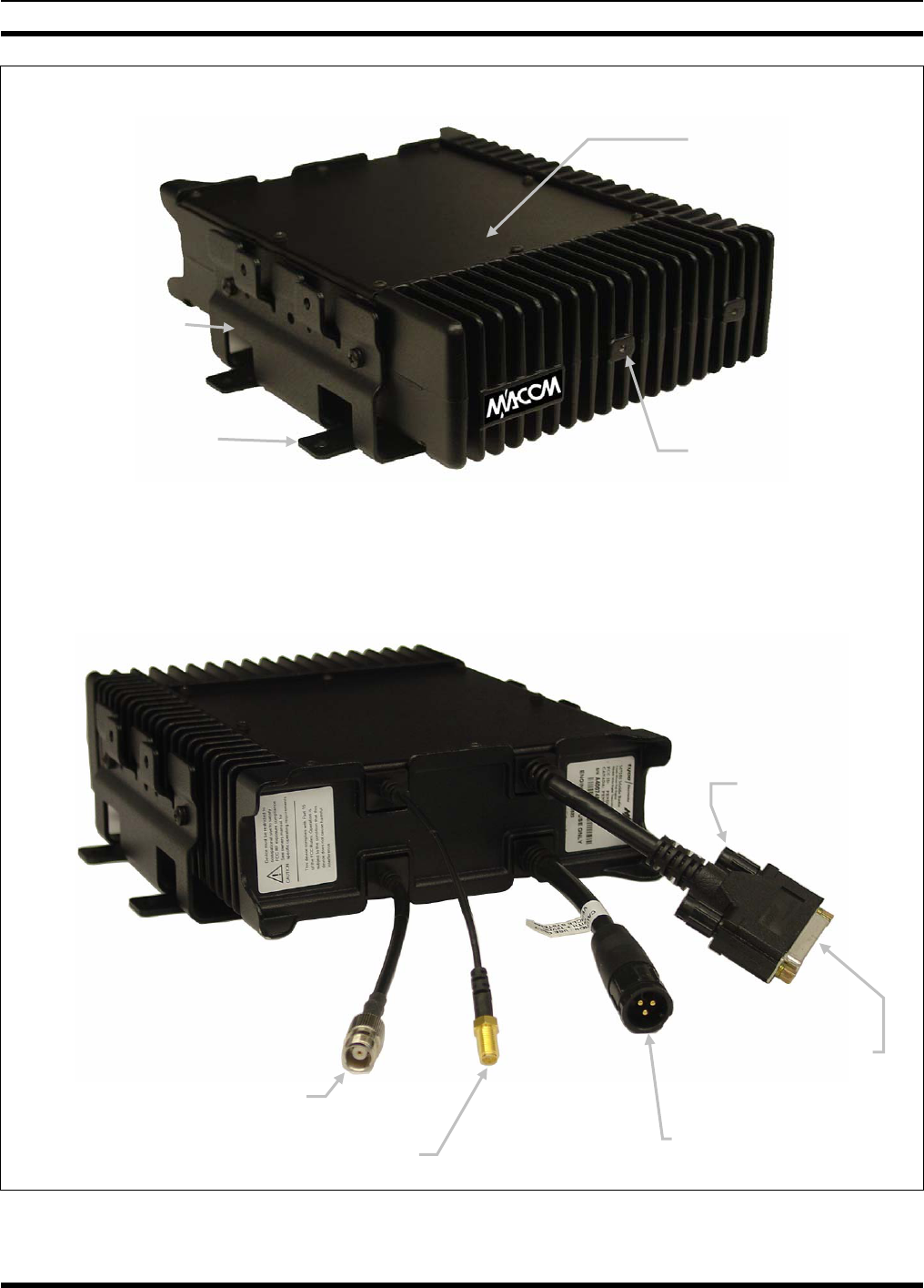
FRONT VIEW
REAR VIEW
(Shown With Installation Cables NOT Connected)
Figure 5-1: Mobile Radio Unit Front and Rear Views
I/O Cable’s
DB-44
Connecto
r
DC Power Cable’s
3-Pin Connector
GPS Antenna Cable’s SMA Connecto
r
Antenna Cable’s
TNC Connecto
r
CAN Port
Connectors
(2 Places)
Mobile Radio Unit
(MRU)
Base Bracket
Base Bracket’s
Mounting Tabs
(4 places) Mounting Holes
(Not used; 2 places)
MM-007024-001
20
5.3 LOCATING COMPONENTS
Plan the mounting locations of all components (radio, control head, antenna, and cables) and determine
the routes for all wiring and cables. Particularly consider the connection of the control head for planning
purposes.
• Determine the customer’s preferences, if any, for location of components. Comply with these
preferences as long as they are consistent with safety recommendations and guidelines presented in
this manual, and other generally accepted professional radio installation practices.
• Nominal dimensions for the radio are 2.8 x 8.8 x 9.3 inches (7.1 x 22.4 x 23.6 centimeters; height x
width x depth). This includes the base bracket and its mounting tabs, but it does not include any
clearance space required for cabling, air circulation, access to mounting hardware, etc.
• Verify sufficient clearance behind the units is provided so cables will not be stressed, crushed,
twisted, or bent at severe angles. Also, the front and sides must have clearance for air circulation,
access to mounting hardware, etc.
• Connections on the radio are made through “pigtail” type cables exiting the rear of the radio. This
design minimizes the stresses associated with mating connections and it allows for easy connector
mating. However, stresses can still be induced if adequate service looping is not employed.
Connections to the CH-103 and CH-103PA Control Heads are made with connectors mounted on the
rear panel of each head instead of “pigtail” type cables.
CAUTION
All cables should have a service loop near each connector end. Do not bend the cables
at severe angles near the connector end. Above all, after all components are installed,
verify no cable is under any tension. Failure to do so may lead to damaged cables,
causing intermittent radio operation or complete radio failure.
MM-007024-001
21
6 MOUNTING THE MOBILE RADIO IN THE TRUNK
This section provides details on mounting the mobile radio in the trunk of the vehicle. See Figure 5-1 and
refer to the respective wiring diagram at the end of this manual as necessary. See section 9 (page 33) for
control head installation procedures.
As an assembled unit, the radio weighs approximately 8 pounds (3.63 kilograms). The preferred mounting
of the radio is on top of a firm, flat surface.
NOTE
Installation Kit MAMV-ZN6X (detailed in Table 4-1 on page 14) contains the most
complete set of materials for installing the radio. Therefore, the following instructions
make repeated reference to this kit. Item numbers given in parenthesis refer to items in
the Installation Kit.
NOTE
Prior to beginning the installation, verify the radio has the proper version of software
installed and it has been configured for customer usage (i.e., channels, personality, etc.).
CAUTION
Though generally mounted in a trunk or remote location, the radio must be kept away
from heat sources. Mounting it in a location which is out of direct sunlight is
recommended but not required. Adequate ventilation space must be provided to the rear
and side fins. The radio reduces its RF output power when its ambient temperature
exceeds approximately +140 o Fahrenheit (+60o Celsius).
WARNING
At a minimum, the mounting surface should be 16-guage (approximately 1/16-inch
thick) steel sheet metal. Mounting to plastic or other material with low tensile and shear
strength could lead to an unsafe and/or failed mounting condition, turning the radio and
its base bracket into a projectile during a high-shock incident such as a motor vehicle
accident. If the selected mounting surface does not meet the minimum 16-guage steel
sheet metal requirement, the surface should be reinforced with a metal backing plate
(not supplied) or it should be reinforced using some other approved mounting method.
CAUTION
Before drilling holes and/or installing mounting screws, verify these operations will not
damage or interfere with any existing vehicle component (fuel tank, fuel line,
transmission housing, existing vehicle wiring, etc.). Always check to see how far the
mounting screws will extend below the mounting surface prior to installation. Always
deburr drilled holes before installing screws.
6.1 BRACKET INSTALLATION
Typically, the radio’s Base Bracket (Item 1 in Table 4-1) is mounted in the vehicle’s trunk, on the top
surface of the trunk tray or the trunk floor. However, it can be suspended from the trunk’s rear deck if the
surface is completely flat, does not require any shimming and the gauge of deck’s sheet metal is high
(16-guage minimum).
Since the radio protrudes several inches from the bracket’s front and back edges, maintain sufficient
distance at the front and back for this and additional clearance. A minimum distance of three (3) inches is
required from the rear edge of the bracket; however four (4) inches or more is recommended to improve
MM-007024-001
22
radio installation and removal ease. A minimum distance of two (2) inches is recommended from the
front edge of the bracket. The bracket is front/back symmetrical, and left/right symmetrical.
As all installations differ, bracket-to-vehicle mounting screws are not included. Steel #10 self-threading
screws are recommended. Sheet metal screws are not recommended. The bracket has ten (10) available
mounting holes; six (6) are underneath the radio when it is attached to the bracket. The following
mounting procedure is recommended:
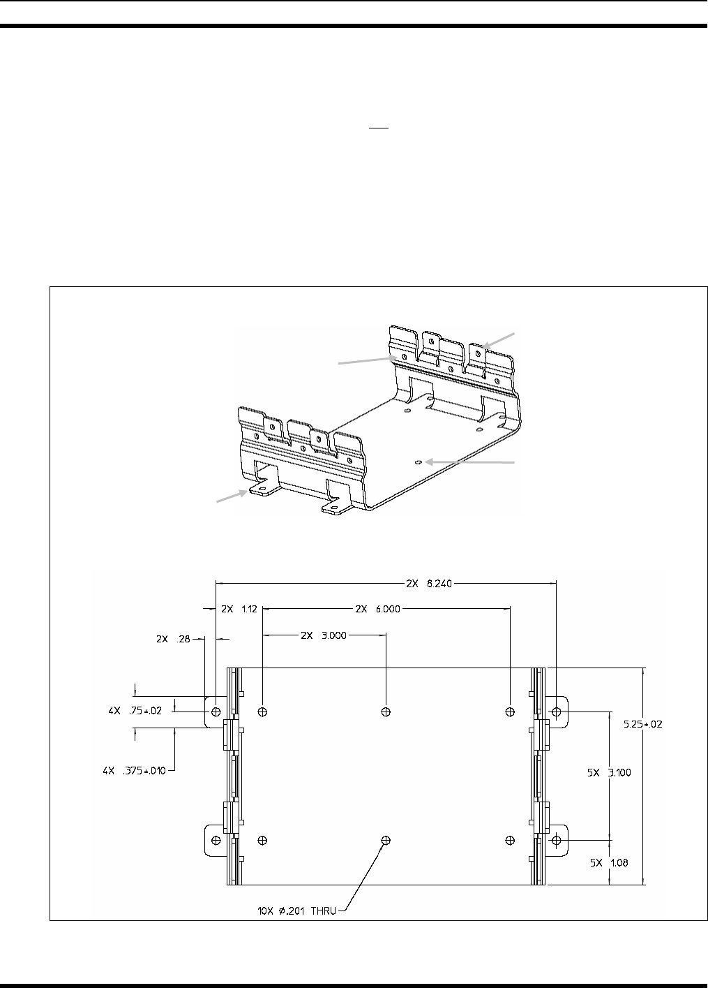
1. Using the Base Bracket (Item 1) as a template and/or the dimensional information shown in Figure
6-1, mark and drill mounting holes into the mounting surface as required. At least six (6) screws are
recommended for proper installation: Four (4) in the screw holes of the bracket’s side tabs and two
(2) in its center-most screw holes. If the installation prevents the installation of six screws, a
minimum of four screws installed in the side tabs’ holes is required.
SIDE & TOP VIEW
TOP VIEW WITH SCREW HOLE DIMENSIONS (In Inches)
Figure 6-1: Base Bracket (Radio Not Shown)
Side Mounting Tabs
(4 places)
Bracket-To-Vehicle
Screw Holes
(10 places)
Bracket-To-Radio Screw Holes
(6 places, 3 each side)
Four (4) Upper-Most
Holes Not Used
(2 each side)
MM-007024-001
23
2. Deburr all newly drilled mounting holes.
3. Set the bracket in place, and install and tighten the mounting screws.
4. Verify the bracket is firmly secured to the mounting surface. A secure mount prevents unreasonable
vibration, which could damage the radio and/or cause its cable connections to loosen.
6.2 MOUNT THE RADIO INTO THE BRACKET
The radio should now be mounted into the bracket according to this procedure:
1. Attach the radio into the Base Bracket using three #8-32 pan-head screws (Item 5 in Table 4-1) per
side. Tighten all six screws with a screwdriver until the lock washer on the screws are fully
compressed and the radio is firm and flush in between the brackets.
2. Check the mounting area for proper clearance for cable service looping and for air circulation, plus an
area to secure and rest the excess cable lengths.
NOTE
Proper mounting is one factor that ensures optimal radio performance. An improperly
mounted radio may experience degradation in the quality of voice and data
communications.
MM-007024-001
24
7 ANTENNA INSTALLATION
7.1 ANTENNA MOUNTING LOCATIONS
WARNING
At this time, review all information presented in the SAFETY INFORMATION
section of this manual (begins on page 5). A transmitting antenna must be installed in
accordance with the guidelines presented in the SAFETY INFORMATION section.
Use Table 1-1 as a guide for determining the best possible mounting
configuration/location in order to reduce human exposure to radio frequency (RF)
electromagnetic energy during transmit mode.
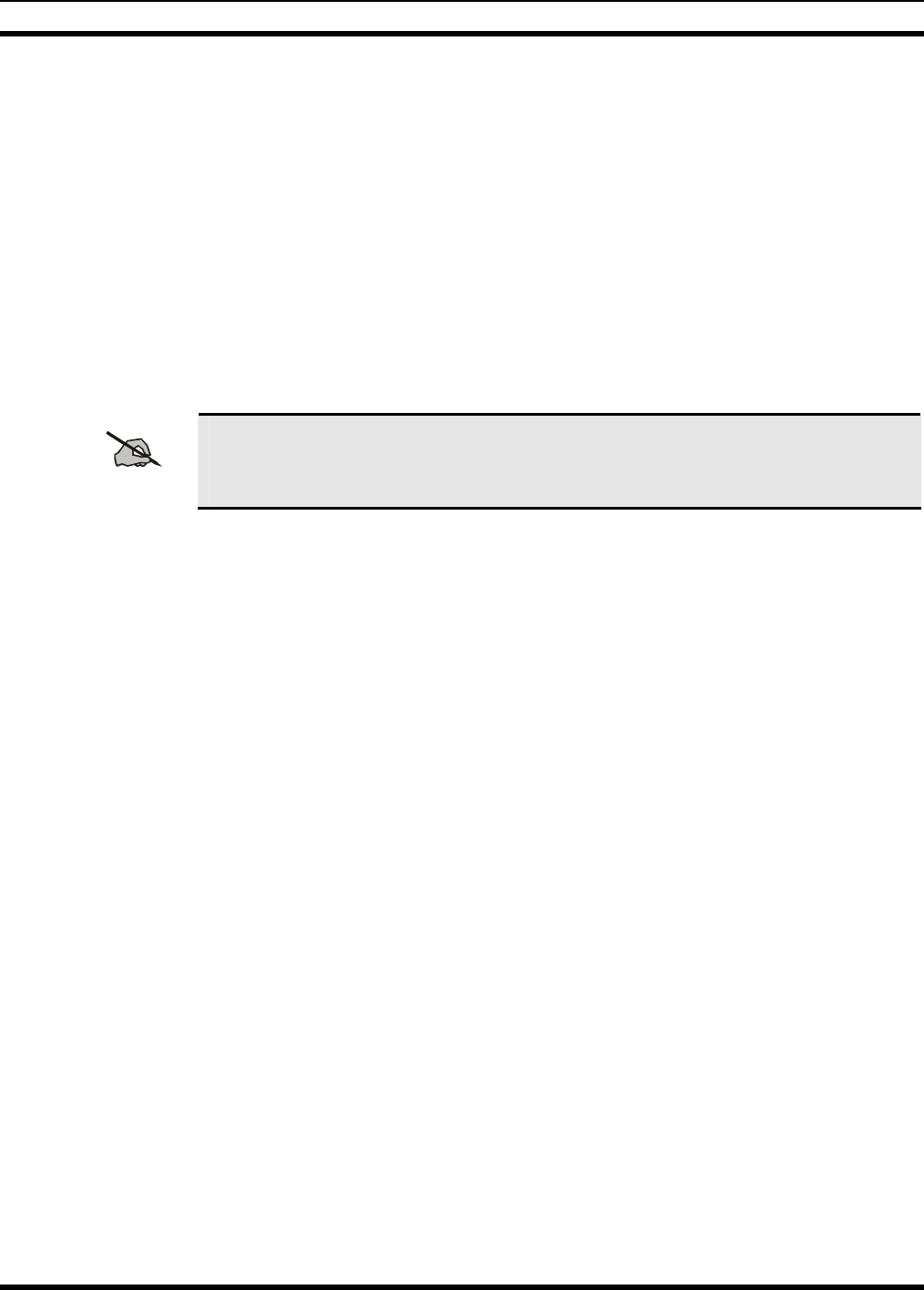
Antennas can be mounted in one of there possible locations on the vehicle as described in the following
subsections. Figure 7-1 shows the recommended locations and antenna part numbers for each location.
Also, see Table 4-2 for additional information. Always follow manufacturer’s instructions when
mounting an antenna.
TYPICAL VEHICLE TOP VIEW
❶Vehicle Rooftop, Direct Center ❸Trunk Lid, Direct Center
MAMV-AN3J = 700/800 MHz MAMV-AN3K = 700/800 MHz Elev. Feed
MAMV-AN3K = 700/800 MHz Elev. Feed
MAMV-AN3V = Combo GPS/700/800 MHz
❷Vechicle Rooftop, Center-Rear
MAMV-AN3J = 700/800 MHz
MAMV-AN3L = GPS Rx Only
Figure 7-1: Recommended Antenna Mounting Locations (With Antenna Part Numbers)
MM-007024-001
25
7.1.1 Direct Center or Center-Rear of Rooftop
The center of the vehicle’s roof is the best location for the rooftop antenna (❶in Figure 7-1). For optimal
performance, the mounting area under the antenna must be a flat with a minimum radius of six (6) inches
of metallized ground plane. It must be located directly in the center of the roof for RF safety. Other
obstructions such as a light bar or another antenna may prevent the antenna from being mounted in the
direct center of the roof. In this case, the antenna should be mounted a minimum of one foot away from
and behind the obstruction but in the middle of the roof with respect to the left and right sides of the
vehicle (❷in Figure 7-1).
7.1.2 Center of Trunk Lid
Certain vehicles do not allow for the antenna to be placed in the center or center-rear of the roof. In this
case, the next best location for the antenna is in the direct center of the trunk lid (❸in Figure 7-1). In this
case, an elevated-feed-point antenna is recommended. Although this type of antenna does not require a
metallized ground plane, it must be located directly in the center of the trunk lid for RF safety.
WARNING
The antenna cable of M/A-COM approved antennas should never be cut to a shorter
length. Instead, excess cable must be tied and stowed. This not only prevents the
antenna from radiating above its intended or configured power, but it also allows for
future installation considerations. Installations requiring longer cables are to be treated
as custom and separately specified.
7.2 ANTENNA INSTALLATION PROCEDURE
NOTE
An antenna must be installed before completing the radio installation.
7.2.1 Install and Connect Mobile Radio Antenna
Table 4-2 lists several types of mobile radio antennas available for use with the radio. As presented in the
previous section, various mounting locations exist. Optimal performance is achieved via a rooftop
antenna mounted in the direct center of the motor vehicle’s roof:
1. Once the mounting location is selected, refer to the antenna manufacturer’s mounting and testing
instructions included with the antenna kit for installation guidance. If necessary, contact M/A-COM’s
Technical Assistance Center (see page 13 for contact information).
2. Route the cable from the antenna to the rear of the radio. The cable should be kept out of casual
contact from persons within the vehicle. Tie and stow as necessary.
3. Connect the antenna cable’s TNC plug-type (male) connector to the radio’s TNC receptacle-type
(female) “pigtail” type RF connector at the rear of the radio. Mate the two connectors and turn the
plug clockwise until finger-tight.
This will be a temporary connection until the radio and antenna can be tested after the installation is
complete. The antenna needs to be connected in case of accidental RF transmission.
MM-007024-001
26
7.2.2 Install and Connect GPS Antenna
The radio is equipped with a GPS receiver which requires connection to an externally-mounted GPS
antenna if the GPS functions will be utilized.
The SMR/GPS combo antenna kit includes a GPS antenna built into the base of the mobile antenna. No
extra holes are required for the GPS cable when using this antenna. The antenna must be kept at least six
(6) inches away from any other antenna mounted on the vehicle and have at least six inches of surface
ground plane beneath it.
1. Once the mounting location is selected, refer to the antenna manufacturer’s mounting and testing
instructions for installation guidance. If necessary, contact M/A-COM’s Technical Assistance Center
(see page 13 for contact information).
2. Route the cable from the GPS antenna to the rear of the radio. The cable should be kept out of casual
contact from persons within the vehicle.
3. Connect the GPS antenna cable’s SMA plug-type (male) connector to the radio’s SMA receptacle-
type (female) “pigtail” type RF connector at the rear of the radio. Mate the two connectors and turn
the plug clockwise. Tighten with a pair of slip-jaw pliers.
NOTE
Do not attempt to alter the length of cable from the GPS antenna. The SMA connector
on the end of the antenna cable is not field-replaceable. Tie and stow excess cable as
necessary.

MM-007024-001
27
8 RADIO DC POWER INSTALLATION
Refer to the wiring diagrams at the end of this manual. The diagram in section 19 (page 61) includes
mobile radio with the CH-103 Control Head. The diagram in section 20 (page 63) is nearly the same with
the exception of the three cables designed for use with the CH-103PA Control Heads. Power connections
to either head are exactly the same.
8.1 ON/OFF POWER WIRING CONFIGURATIONS
The mobile radio can be wired in a motor vehicle in various ways to accommodate the user’s preferences.
In all cases, its red power wire must be connected through an in-line fuse to raw battery power (positive
battery terminal). The white ignition wire of the radio’s DC Power Cable is only used for the Data-Only
(i.e., no Control Head) radio and it is the only means for turning its power on. An in-line switch for
switched battery power to the radio must never be considered unless the user has the discipline to turn off
the radio through the Control Head’s on/off button or through a separate switch wired to the ignition
sense wire. Failure to wait for the radio to completely power down before disconnecting battery power
will not damage the radio; however, it will result in the loss of settings that have changed (e.g., channel
number, volume setting, etc.) during the operating session.
Integral to the power management system of the CH-103 and CH-103PA Control Heads is a 60-second
power-off Time-Delay Relay (part number MAMROS0088). The addition of this relay is required to
remove the relatively high standby (off-state) quiescent-current (30 mA) consumed by the Control Head
that would otherwise reduce the charge state of the vehicle’s battery. The radio by itself does not require
the relay, as its standby quiescent-current is typically below 1 mA. This is especially true in the case of
the Data-Only radio configuration since it has no control head. However, because the CH-103 and
CH-103PA do require the relay, it is advisable to connect the relay so both the radio and Control Head are
shut down together. This relay reduces quiescent-current for the radio/control head pair below 2 mA and,
if installed correctly, will work in conjunction with all on/off power configurations described below.
On/Off power functions for the radio are controlled by the Control Head or, in the case of a Data-Only
radio, within the radio itself. The following power wiring configurations are supported:
• Radio turns on automatically with vehicle’s ignition switch/key — The white sense wire of the
Control Head’s (or Data-Only radio’s) DC Power Cable is connected to a fused switched power
source, typically identified as “Accessory” power. This source must switch on (up to + battery
voltage potential) when the vehicle’s ignition switch/key turns on, and it must switch off (to near zero
volts) when the ignition switch/key turns off. The required fuse rating is 2 amperes. An ATM fuse
holder and fuse are included with the applicable fuse kit.
• Radio turns on with a manual switch — The white sense wire of the Control Head’s (or Data-Only
radio’s) DC Power Cable is connected to one side of a manual toggle switch and the other side of this
switch is connected to a fused vehicle power source. This configuration is used when, for example,
the radio must remain on even when the ignition key must be removed from the vehicle and a
separate on/off switch is acceptable. The required fuse rating is 2 amperes if no other devices share
the switch. If other devices share the switch, the 2-ampere ATM fuse must be spliced in the white
wire on the load/switched power side of the switch.
• Radio turns on with Control Head’s on/off button (“hot wired”) — Standard software
configurations allow turning on the radio with the Control Head’s on/off button. This configuration
may be desired if, for example, the radio must remain on even when the ignition key must be
removed from the vehicle. In this case, the white sense wire of the Control Head’s DC Power Cable is
connected to vehicle chassis ground and the Time-Delay Relay’s white wire is connected to the
relay’s red (power input) wire. In fact, the Time-Delay Relay’s function is rendered useless, so the
MM-007024-001
28
relay could be completely bypassed in this configuration. Similarly, the 2-ampere ATM fuse and fuse
holder included in the fuse kit are not needed.
CAUTION
Because the “hot wired” configuration renders the function of the Time Delay Relay
useless, the Control Head will draw substantial quiescent current continuously from
the battery when turned off. For this reason, the “hot wired” configuration should only
be used in highly-controlled or temporary situations.
NOTE
A software configuration parameter can be set to disable the function of the Control
Head’s on/off power button. This may be desired, for example, where frequent contact
with the button is unavoidable and detrimental to usage.
8.2 POWER INSTALLATION PROCEDURE
Prepare to connect battery power to the radio through the vehicle’s engine firewall. Plan the wire route
carefully, using an existing access hole through the firewall if possible. Alternately, drill a new hole
approximately 3/8-inch in diameter and install a small rubber grommet to protect the wire from chafing
on the hole’s sharp metal edge. To prevent fumes from entering the passenger compartment, this
hole/grommet/wire combination must also be sealed with a silicon-based sealer before completing the
installation.
8.2.1 Install Main Fuse Holder, Time-Delay Relay, and Fuse Block
Refer to Figure 8-1 and Figure 8-2 for parts included the radio’s fuse kit. Follow the steps below for
connecting the radio to the vehicle’s positive battery power. Also refer to the respective wiring diagram at
the end of this manual.
CAUTION
Do not install the fuse holder, wire, and relay over or in the near vicinity of the engine.
Excessive engine heat can cause permanent damage to these components and can lead
to intermittent electrical connection to the battery.
WARNING
Before making connections to the battery’s positive post, carefully disconnect the
battery’s negative (ground) cable. This will prevent tools or other metallic objects
which come in contact with the battery’s positive terminal from shorting to
vehicle chassis ground, causing sparks or even a fire or an explosion! When
disconnecting the negative cable, cover/insulate the positive post if it is not
already so a tool cannot short between the posts.
A fuse must not be installed in the main fuse holder until all wiring is complete.
This will prevent the unit from powering up prematurely and/or causing an in-
rush of current that could lead to shorting of the battery, sparks, or even fire.
1. The installation’s main ATC Fuse Holder is a part of the Fuse Distribution Rail Kit (part of Item 2 in
Table 4-1). Strip one of the ATC Fuse Holder’s wires and crimp a 3/8-inch ring terminal to it. Ring
terminals are also included with the kit.
2. Verify the fuse is NOT in the Fuse Holder.
MM-007024-001
29
3. Connect the ring terminal directly to the battery’s positive post (or if present, to a stud on the battery’s
main/non-switched power distribution terminal block).
4. Mount the Time-Delay Relay firmly onto a flat surface within the vehicle’s engine compartment and
near the battery but away from sources of excessive heat. Use the various mounting holes in the relay
case as necessary and self-threading screws (not supplied).
5. Strip the Fuse Holder’s other wire and strip the relay’s 10-AWG red wire. Connect these two wires
together using the 10-AWG moisture-resistant insulated butt splice included in the Fuse Distribution
Rail Kit.
6. Strip the relay’s 10-AWG yellow wire. This is its output lead.
7. Strip one end of the 20-foot long 10-AWG red wire supplied in the Fuse Distribution Rail Kit and
connect it to the relay’s yellow wire using a 10-AWG moisture-resistant butt splice.
8. Route the other end of the 20-foot long red wire through a wire-loom then through the grommet in the
firewall. This end of the red wire will later be connected to the Fuse Block clipped on the Fuse
Distribution Rail Assembly (both parts of the Fuse Distribution Rail Kit). The Fuse Distribution Rail
Assembly will be located near the radio in the trunk.
9. Connect the relay’s white wire to a switched power source such as “Accessory” power at the
vehicle’s fuse box. Use an 18-AWG moisture-resistant insulated butt splice and 18-AWG wire. Route
the wire through a wire-loom then through the grommet in the firewall to the fuse box. This must be
the same switched power source (that is later) connected to the Control Head’s white wire; see section
9.5.3 on page 37 for additional information.
10. Continue routing the 20-foot red wire through channels in the vehicle to the location of the radio.
Remove interior panels, door kick panels, etc. Protect the wire from possible chafing as necessary.
11. Mount the Fuse Distribution Rail Assembly (included in the Fuse Distribution Rail Kit; see Figure
8-2) in the vicinity of the radio’s mounting location, but where casual contact is not likely. Use self-
threading screws (not supplied) and any available mounting slots in the DIN rail to mount the block.
NOTE
The Fuse Distribution Rail Assembly has a DIN-type rail allowing additional Fuse
Blocks to be added to it if fuse expansion is necessary in the future, such as for
multiple Control Head installations. The rail may be cut to decrease its length if
necessary, but enough room for at least one Control Head and any additional future
expansion should be considered first.
12. Apply the sticker included in the Fuse Distribution Rail Kit in the vicinity of the Fuse Block as future
reference for service personnel.
13. At the Fuse Block, cut and discard excess length from the 20-foot red wire, strip the end, and connect
it to the Fuse Block according to the instructions included with the block.
MM-007024-001
30
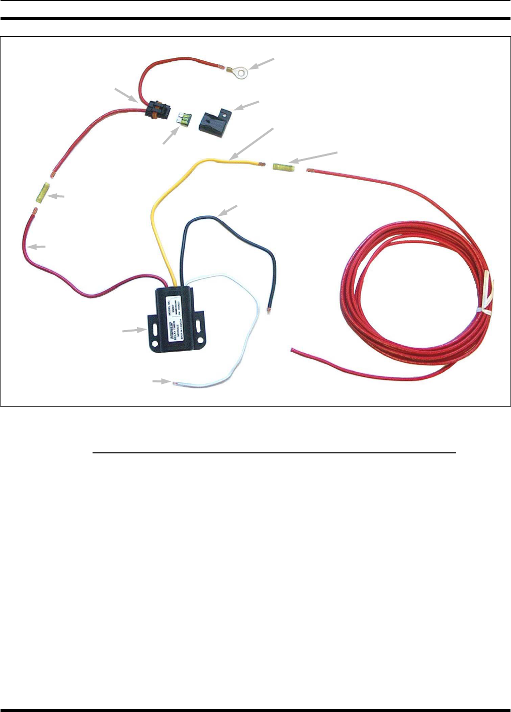
Figure 8-1: Fuse and Power-Off Time Delay Relay Wiring at Battery (Exploded View)
8.2.2 Make Ground Connections at Fuse Block and Time-Delay Relay
1. Strip one end of the 10-AWG black wire (included with the Fuse Distribution Rail Kit) and crimp a
3/8-inch ring terminal to it.
2. Near the Fuse Distribution Rail Assembly, locate an area of vehicle chassis ground within one foot of
the assembly and strip the area of any paint or dirt to expose a bare metal surface.
3. Drill a hole as necessary and connect the ring terminal to chassis ground. Use a self-threading screw
or other appropriate hardware to ensure a reliable metal-to-metal contact. Tighten securely.
4. Cut the black wire to a length long enough to reach a green-yellow Grounding Block on the Fuse
Distribution Rail Assembly, plus length for a service loop. Strip the end and connect it to a
Grounding Block in accordance with the instructions provided with the kit. Adjacent Grounding
Blocks are electrically connected together, so the black wire will ground both blocks.
5. Obtain the radio’s DC Power Cable (Item 3 in Table 4-1) and temporarily connect it to the radio.
Next, cut its black (negative) wire to a length long enough to reach a Grounding Block, plus length
for a service loop. Strip the end of the wire and connect it to a Grounding Block in accordance with
the instructions provided with the kit.
3/8-Inch Ring Terminal:
To Positive (+) Battery Post
ATC Fuse Holder’s Cap
In-Line ATC
Fuse Holde
r
Insulated Butt Splice
20-Foot
Red Wire
(Cut To Required
Length)
30-Amp
ATC Fuse
(Green)
Insulated
Butt Splice
Time-Delay Relay
Relay’s White Wire:
To Switched Power Source
Relay’s Yellow Wire: Output (To Load)
Relay’s Black Wire:
To Chassis Ground
Relay’s Red Wire:
+12-Volt Battery
Power Input
To ATC
Fuse Block
MM-007024-001
31
(Image Not Currently Available)
Figure 8-2: Wiring to the Fuse Distribution Rail Assembly (Exploded View)
6. Label and route the DC Power Cable’s white wire to the vehicle’s fuse box. Tie and stow as necessary
so the wire remains out of the way of casual contact and wire chafe is avoided.
NOTE
The Control Head wakes up the radio via the CAN port when power is applied.
However, connection of the white sense wire may be needed in future configurations
that do not use the Control Head (e.g., Data-Only applications). Therefore, it is
recommended that the white wire be labeled, routed up to the vehicle’s fuse box,
coiled, and stowed for possible future use rather than be cut from the DC Power Cable.
7. In the engine compartment, strip the Time-Delay Relay’s black wire and crimp a 3/8-inch ring
terminal to the wire.
8. Locate a nearby section of vehicle chassis ground and strip the area of any paint or dirt to expose a
bare metal surface.
9. Drill a hole as necessary and connect the relay’s black wire to chassis ground using a self-threading
screw.
CAUTION
Do NOT connect the relay’s black wire directly onto the negative terminal of the
battery!
8.2.3 Complete Fuse Block and DC Power Cable Connections
1. Cut the red (positive) wire of the DC Power Cable to a length long enough to reach the Fuse Block
plus length for a service loop.
MM-007024-001
32
2. Strip the end and connect it to the output power distribution side of the Fuse Block in accordance with
the instructions included with the block.
3. Mate the DC Power Cable’s connector to the radio’s 3-pin power connector as follows: Visually align
the key and firmly push and turn the outer locking ring clockwise until it stops. A click will be sensed
to confirm proper mating.
CAUTION
Upon connection, verify the DC power cable is not under any stress, a service loop is
maintained, and the cable can be properly tied and stowed.
4. Install the 15-Amp ATC fuse included in the Fuse Distribution Rail Kit into the Fuse Block’s fuse
slot.
CAUTION
Installing a fuse with the wrong amperage rating could cause an unsafe condition
and/or a prematurely blown fuse. Verify the correct fuse value for the radio is installed.
The color of the 15-amp fuse is blue.
5. Tie and stow all cables/wires as necessary so they remain out of the way of casual contact, and so
wire chafe is avoided.
CAUTION
When servicing the radio and/or control head, always manually turn the units off and
then pull the main power fuse in the engine compartment.
MM-007024-001
33
9 CONTROL HEAD INSTALLATION
9.1 GENERAL INFORMATION
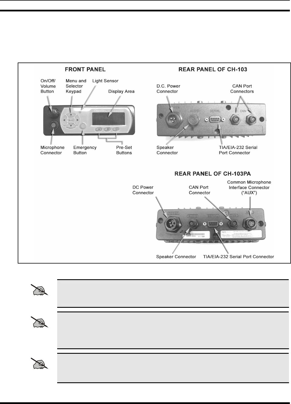
Figure 9-1 below illustrates CH-103 and CH-103PA Control Head interfaces.
Figure 9-1: CH-103 and CH-103PA Control Head Front and Rear Panels
NOTE
Prior to installation, verify the Control Head has the proper software version installed
and verify it has been configured for customer usage (i.e., channels, personality, etc.)
NOTE
Because the MAMV-ZN6Y Installation Kit (see Table 4-3 on page 15 for complete
contents) contains the most complete set of materials for installing the
CH-103/CH-103PA Control Head, the following instructions make repeated reference to
this kit. Item numbers given in parenthesis below refer to items in the Installation Kit.
NOTE
For the CH-103PA Control Head, in addition to the items listed in Table 4-3, other
optional accessories are also required to complete the installation. These optional
accessories are discussed in the following pages.
MM-007024-001
34
9.2 BRACKET INSTALLATION
CAUTION
When drilling holes, be careful to avoid damaging some vital part of the vehicle (fuel
tank, transmission housing, etc.). Always check to see how far the mounting screws
will extend below the mounting surface prior to installation. After drilling pilot holes,
remove all metal shavings from them (deburr) before installing mounting screws.
9.2.1 Standard U-Shaped Bracket
1. Using the U-shaped bracket (Item 1 in Table 4-3) as a template, mark and drill mounting holes
into the mounting surface as required. It can be mounted under or on top of the dash as required
and as space permits. Screws for mounting the bracket are not included, as all installations differ.
Self-threading screws are recommended.
2. Install and tighten the mounting screws.
3. Verify the bracket is held firmly to the mounting surface. Firm mounting prevents unreasonable
vibration, which could damage the Control Head and/or cause its cable connections to loosen.
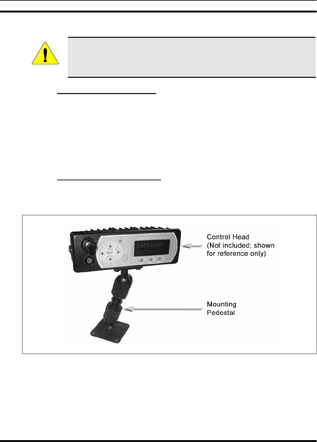
9.2.2 Mounting Pedestal (Optional)
An optional mounting pedestal, part number MACDOS0012, may be purchased separately to replace the
standard U-shaped mounting bracket. See Figure 9-2.
Figure 9-2: Optional Control Head Mounting Pedestal (Part Number MACDOS0012)
9.3 ATTACH CONTROL HEAD TO BRACKET
The following procedure applies to the standard U-shaped mounting bracket:
1. Slide the Control Head into the bracket then start a thumbscrew (Item 2 in Table 4-3) in each side by
inserting it through the hole in the bracket and then into the threaded hole in the side of the Control
Head. Turn each thumbscrew clockwise as observed from the head of the screw.
MM-007024-001
35
2. The Control Head can be positioned at various angles for best display viewing. As necessary, turn it
on the thumbscrews to a good position (typically, as viewed from the driver’s seat) and then tighten
both thumbscrews until the Control Head is held firmly in place.
9.4 CAN CONNECTIONS
9.4.1 General Information
Because CAN devices do not provide their own termination, the CAN bus needs to be terminated at both
ends for proper operation.
The CH-103 Control Head has two ports on the rear panel to support “daisy-chaining” of multiple Control
Heads or other CAN devices. When a CH-103 is in the middle of a chain (e.g., radio on one end and
another Control Head on the other), two separate CAN cables connect to the two ports. When the CH-103
is at the end of a chain of devices, one CAN port connects to the previous CAN device and the other port
needs to be terminated with a CAN Terminator (part number MACDOS0010).
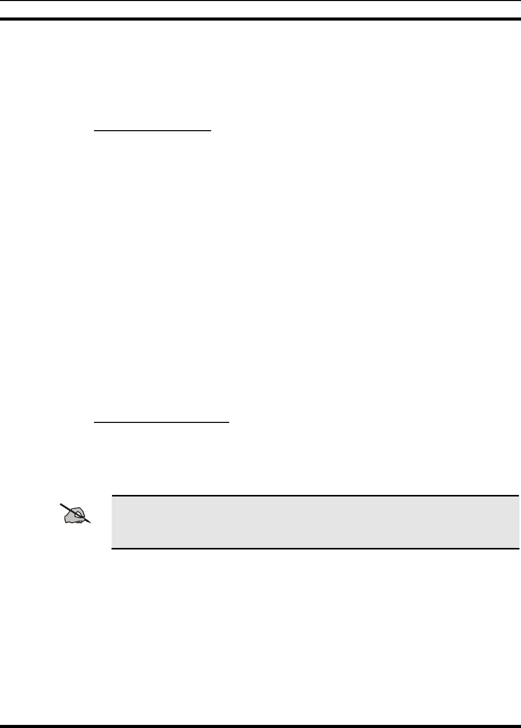
The CH-103PA Control Head has only one CAN port. A CAN Y-cable (part number MACDOS0017-
BR010 for right-angle connector or MACDOS0017-BN010 for straight connector; listed in Table 4-4)
needs to be connected to the rear of the CH-103PA to properly terminate the CAN chain. If the
CH-103PA is in the middle of a chain of CAN devices, one CAN cable will connect to one leg of the
Y-cable and another CAN cable will connect to the other. When the CH-103PA is the only CAN device
or is at the end of a chain of devices, one leg of the Y-cable goes to the previous CAN device and the
other needs to be terminated with the CAN Terminator provided in the Control Head Installation Kit.
The radio has two CAN port connections on its I/O pigtail cable. Like the Control Head, it can be
connected either at an end or in the middle of a CAN chain. However, for logistical purposes, it typically
is an end point and provides a termination when a CAN Terminator is connected to one of the two CAN
connectors. The CAN cable from a Control Head then connects to the other connector.
9.4.2 Make CAN Termination
When mating any CAN connection (terminators and cables), visually align the ¾-moon-shaped keys of
the connectors, and then gently push and turn the outer locking ring of the plug (male) connector
clockwise until it stops. A mild click will be sensed to confirm proper mating. Per the specific Control
Head being installed, follow the respective procedure in one of the following subsections.
NOTE
Without visual alignment as a guide, it is possible with excessive force to mate the
CAN connectors improperly. Damage to the connector(s) may result. Therefore, visual
alignment is recommended when mating CAN connectors.
9.4.2.1 CH-103 Control Head CAN Termination
Connect the CAN Terminator (Item 3 in Table 4-3) onto one of the two smaller 3-pin connectors on the
rear of the CH-103. This makes the CAN termination at the Control Head end of the CAN chain.
Continue with section 9.4.3.
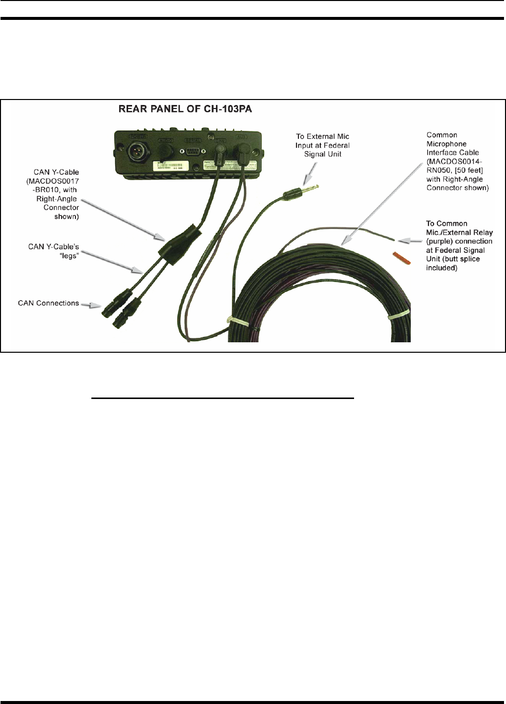
MM-007024-001
36
9.4.2.2 CH-103PA Control Head CAN Termination
Connect the plug (male) connector of the CAN Y-cable to the rear of the CH-103PA and connect the
CAN Terminator (Item 3 in Table 4-3) to one leg of the Y-cable. See Figure 9-3. See Table 4-4 for CAN
Y-cable part numbers.
Figure 9-3: CH-103PA CAN Y-Cable and Common Microphone Interface Connections
9.4.3 Connect Control Head to Radio Via CAN Cable
1. Route the CAN Cable (Item 4 in Table 4-3) through the vehicle’s channeling to the radio. Remove
interior panels, door kick panels, etc., as necessary. Protect the cable from possible chafing as
necessary.
2. Attach the CAN Cable’s connector to one of the two CAN port connectors on the radio’s I/O cable.
3. CH-103 Control Head: Connect the other end of the CAN Cable to the open CAN port connector at
the rear of the Control Head.
CH-103PA Control Head: Connect the other end of the CAN Cable to the open leg of the CAN
Y-cable.
4. Loop, tie and stow the excess cable as necessary.
9.5 CONTROL HEAD POWER CABLE INSTALLATION
Plan the cable’s route carefully. For the red wire, ensure a route that will not crush or damage the wire in
any way.
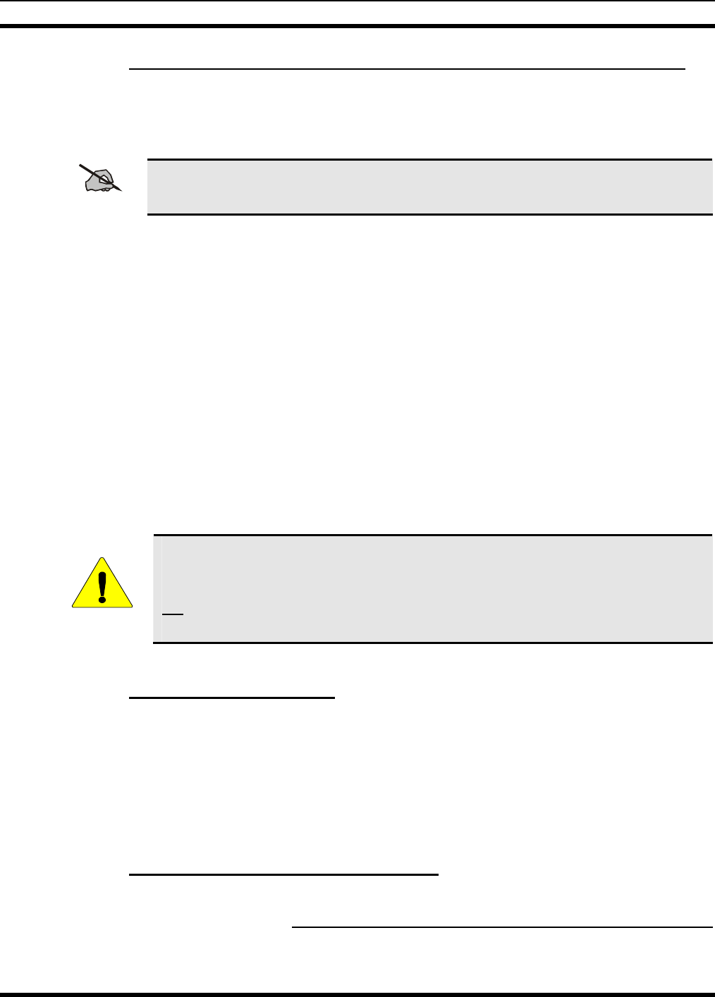
MM-007024-001
37
9.5.1 Install Fuse Holder and DC Power Cable and Make Power Connection
The Control Head has a moderately high quiescent-current drain so red wire power connection to the
output/load side of the Time-Delay Relay (relay’s yellow wire) through the Fuse Block is highly
recommended. Refer to the respective wiring diagram at the end of this manual.
NOTE
Do not share the Control Head’s fuse with any other device. Doing so can cause excess
current to flow through the fuse, causing it to blow unnecessarily.
1. Connect the Control Head’s DC Power Cable (Item 5 in Table 4-3) to the large 3-pin connector at the
rear of the Control Head. Visually align the key and gently push and turn the outer locking ring
clockwise until it stops. A click will be sensed to confirm proper mating.
2. At the back of the Control Head, form a cable service loop of at least six (6) inches, and tie and stow
the cable as necessary.
3. Route the cable’s red (positive power) wire through channels in the vehicle to the location of the Fuse
Distribution Rail Assembly. Remove interior panels, door kick panels, etc. Protect the wire from
possible chafing as necessary.
4. Remove the end stop on the fuse side of the Fuse Distribution Rail Assembly, clip the Fuse Block
included in the Fuse Distribution Accessory Kit (Item 6 in Table 4-3) onto the DIN rail next to the
radio’s block, and snap the end stop back onto the DIN rail so both blocks are firmly fixed to the rail.
Refer to the instructions included with the kit as necessary.
5. Strip and connect the red wire to the load-side of the newly installed Fuse Block.
6. Install the 5-amp ATC fuse included in the kit into the Fuse Block’s fuse slot.
CAUTION
The fuse for the Control Head is rated at 5 amperes. Installing the wrong fuse value
could lead to damage. Verify the Control Head has the correctly rated fuse! The color
of a 5-amp ATC fuse is tan. The 15-amp (blue) ATC fuse included in the kit should
not be used for CH-103/CH-103PA Control Head power; it can be returned to stock or
stored as a spare for the radio.
9.5.2 Make Ground Connection
1. At the back of the Control Head, locate a nearby section of vehicle chassis ground and strip this area
of any paint or dirt to expose a bare metal surface.
2. Cut the black wire of the Control Head’s DC Power Cable as short as possible, but long enough for a
service loop, then strip it and crimp a 3/8-inch ring terminal (included in the fuse kit) to it.
3. Drill a hole as necessary and screw this ring terminal to chassis ground. Use a self-threading screw or
other appropriate hardware to ensure a reliable metal-to-metal contact.
9.5.3 Connect DC Power Cable’s White Wire
A review of the information presented in Section 8.1 may be beneficial at this time. As required per
the chosen power-up configuration, follow one of the three procedures presented in the sub-sections
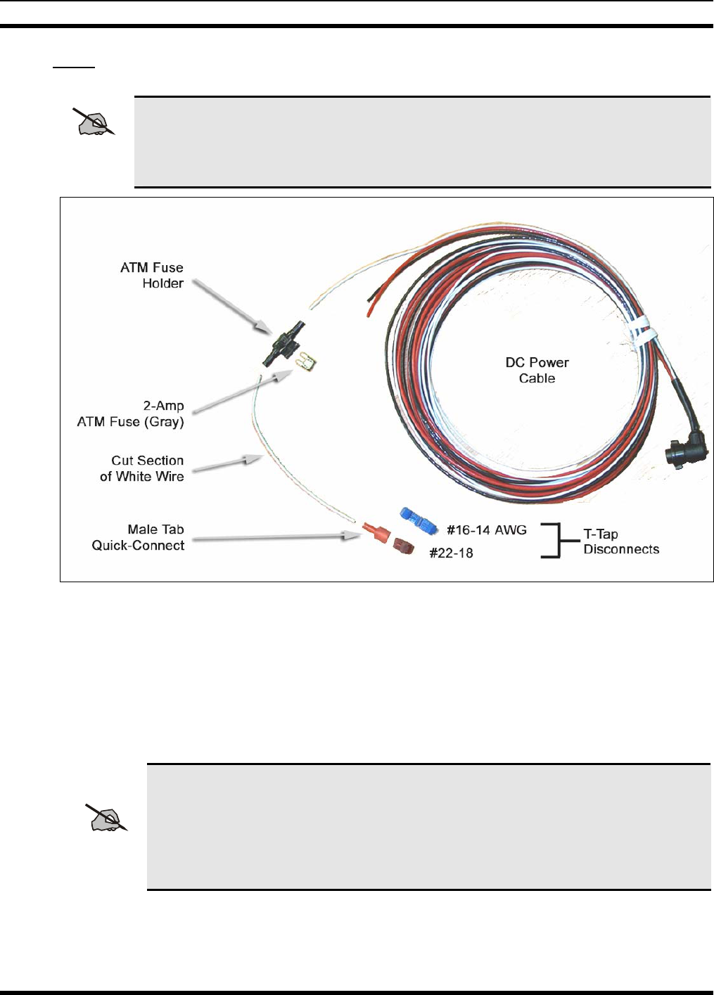
MM-007024-001
38
below. The Control Head’s DC Power Cable and associated fuse and wire terminal devices are shown in
Figure 9-4.
NOTE
Only the Control Head’s white wire and the Time-Delay Relay’s white wire must be
connected to the ignition or switched power sense. When this vehicle line is asserted (i.e.,
power switched on), the Control Head automatically powers-up the radio via the CAN
connection.
Figure 9-4: Connection of White Ignition Sense Wire
9.5.3.1 Control Head and Radio Turn on with Vehicle’s Ignition Switch/Key
With this wiring configuration, the Control Head and radio automatically turn on and off with the
vehicle’s ignition switch/key. The white wire of the Control Head’s DC Power Cable is typically
identified as the “white ignition switch wire” or the “ignition sense wire.” In this configuration, the white
wire connects to a switched power source, typically identified as “Accessory” power, that switches on and
off with the vehicle’s ignition switch/key.
NOTE
The white ignition sense wire must be connected to a fused power source that switches
from approximately zero volts to approximately +13.6 volts when the vehicle’s ignition
switch/key is turned from the OFF position to the ACCESSORY and RUN positions.
Use of a switched power source that is subject to voltage changes as a result of other
actions, such as opening a vehicle door, may result in undesirable radio operation and/or
a degradation of radio performance.
1. Locate the switched ignition or “Accessory” power wire (typically at or near the vehicle’s fuse block
or in a vehicle wiring harness) that will be used for the switched ignition power source. It may be
necessary to consult the vehicle manufacturer’s wiring diagram.
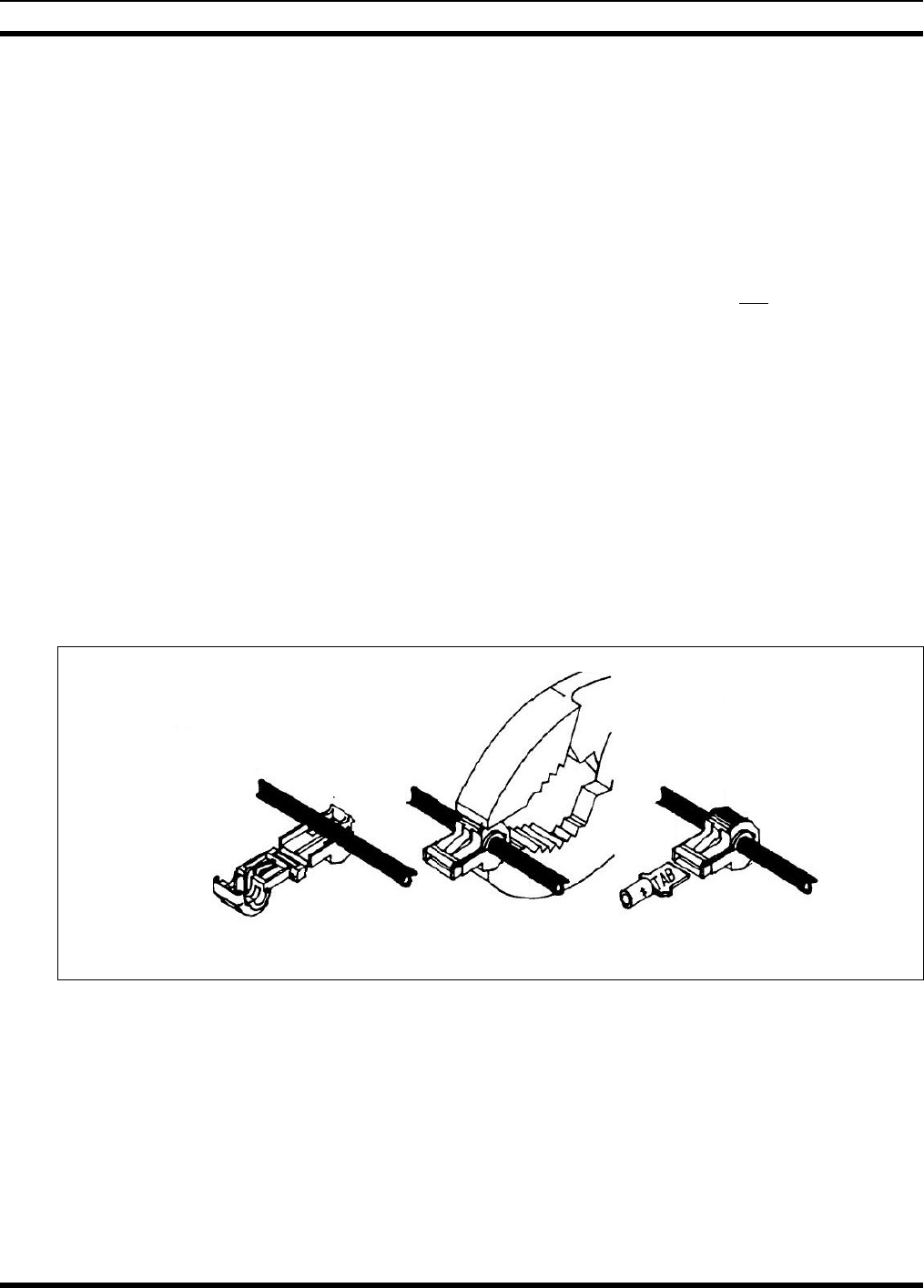
MM-007024-001
39
2. Route the white wire of the Control Head’s DC Power Cable from the back of the head to an area
near the switched ignition power source. At the back of the head, be sure to maintain a cable service
loop of at least six (6) inches.
3. Cut a short section (6 to 8 inches) off the end of the white wire and strip each end of this short wire.
4. Extend the length of the Time-Delay Relay’s white wire so that it reaches the white wire of the
Control Head’s DC Power Cable. Use the 18-AWG moisture-resistant butt-splice included in the fuse
kit and extra white wire. Extra wire is not included, but in most cases there will be enough extra white
wire from the DC power cable to accommodate this wire extension. Cut excess length from this wire.
5. Crimp the male-tab quick-connect terminal to one end of both the short wire and the extended wire
from the relay. Refer to the respective wiring diagram at the end of this manual.
6. Crimp the ATM fuse holder to the other end of the short wire. The holder has built-in crimpable
joints.
7. Cut the excess length from the white wire of the Control Head’s power cable, strip it, and crimp it to
the other side of the ATM fuse holder.
8. Pull enough of the switched ignition source wire out of its harness so one of the T-tap quick-
disconnect terminals may be attached to it.
9. Two T-tap quick-disconnect terminals are included in the kit. Based on the gauge of wire, select the
proper terminal size: Red is for 22 to 18-AWG wire and blue is for 18 to 14-AWG wire.
10. Attach the selected T-tap quick-disconnect terminal by fitting the wire into its wire groove and
snapping the two halves together with a pair of pliers as shown in Figure 9-5.
Diagram Courtesy of 3M Corp.
Figure 9-5: Attaching T-Tap Quick-Disconnect Terminals
11. Push the male-tab quick-disconnect terminal into the T-tap quick-disconnect terminal’s inlet until it is
fully engaged.
12. Install the 2-amp ATM fuse into the fuse holder. It is recommended that a piece of electrical tape be
wrapped around the fuse connection to keep the fuse from being jostled out of the holder.
13. Tie and stow these wires as necessary so they remain out of the way of casual contact and wire chafe
is avoided.

MM-007024-001
40
9.5.3.2 Control Head and Radio Turn On with a Manual Switch
With this wiring configuration, the Control Head and radio are manually turned on and off via an on/off
switch mounted separately from the Control Head and radio, not through the vehicle’s ignition
switch/key. This configuration is used when, for example, the radio must remain on even when the igni-
tion key must be removed from the vehicle and a separate on/off switch is acceptable. In this
configuration, the white wire connects to a switched power source such as a toggle switch mounted on the
vehicle’s dash.
1. Route the white wire of the Control Head’s DC Power Cable from the back of the unit to an area near
the on/off switch’s location. At the back of the Control Head, be sure to maintain a cable service loop
of at least six (6) inches.
2. Cut a short section (6 to 8 inches) off the end of the white wire and strip the ends.
3. Extend the length of the Time-Delay Relay’s white wire so that it reaches the switch. Use the
18-AWG moisture-resistant butt-splice included in the fuse kit and extra white wire. Extra wire is not
included, but in most cases there will be enough extra white wire from the DC power cable to
accommodate this wire extension. Cut excess length from this wire.
4. For a new on/off switch (not supplied):
(a) Tap a wire off non-switched battery power from the vehicle’s fuse box with an 18-AWG wire.
(Use wire remaining from the power cable, if available.) Keep wiring as short as possible and use
approved wiring methods. Use techniques presented in section 9.5.3.1 as a reference.
(b) Strip and crimp this tap to one side of the ATM fuse holder included in the fuse kit. The fuse
holder has built-in crimpable joints.
(c) Crimp the short wire to the other side of the ATM fuse holder and connect the other end of this
wire to the common terminal of the manual switch.
(d) Connect both the white wire of the power cable and the extended wire from the relay to the load
(switched) side of the manual switch.
For an existing switch:
(a) Crimp the short wire to one side of the ATM fuse holder and connect the other end to the load
(switched) side of the manual switch.
(b) Crimp the both white wire of the power cable and the extended wire from the relay to the other
side of the ATM fuse holder.
5. Install the 2-amp ATM fuse into the fuse holder. It is recommended that a piece of electrical tape be
wrapped around the fuse connection to keep the fuse from being jostled out of the holder.
6. Tie and stow these wires as necessary so they remain out of the way of casual contact and wire chafe
is avoided.
7. Label this power switch accordingly. For example: “RADIO ON/OFF.”
9.5.3.3 Control Head and Radio Are “Hot Wired”
In the “hot-wired” configuration the Control Head and radio are turned on and off only by the Control
Head’s on/off power button located on the front of the unit. This configuration should only be used in a
temporary setting in which the operator keeps in mind that the Control Head must be turned off when not
in use to avoid unnecessarily discharging the vehicle’s battery. Furthermore, even when off, the Control

MM-007024-001
41
Head will still draw substantial current to eventually discharge the battery over a reasonably short period
of time.
In this configuration, the Control Head’s white wire is simply grounded to the vehicle’s chassis. The
ATM fuse and fuse holder included in the fuse kit are not required in the “hot wired” configuration.
1. Connect white wire of the Control Head’s DC Power Cable to the same place that the black (ground)
wire is attached to ground. In other words, ground the white wire along with the black wire. Use a
#10 ring terminal (not included). At the back of the Control Head, be sure to maintain a cable service
loop of at least six (6) inches.
2. Using an approved wiring method, splice the following three (3) wires together: the Time Delay
Relay’s white and red wires, and the wire from the load-side of the 30-ampere ATC fuse holder.

MM-007024-001
42
10 DATA-ONLY RADIO CONNECTIONS
The Data-Only configuration of the radio has no Control Head. The only difference in connections from
an installation with a Control Head is with respect to ignition sense wiring. For a Data-Only radio, follow
the procedure described in either section 9.5.3.1 or 9.5.3.2, except where the white wire of the Control
Head’s DC Power Cable is referenced, make the connections with the white wire of the radio’s DC
Power Cable instead.
NOTE
The ignition sense is the only means for turning on/off the Data-Only radio. The “hot
wired” configuration cannot be utilized for the Data-Only radio, since this configuration
does not employ the DC Power Cable’s white wire.
MM-007024-001
43
11 MICROPHONE INSTALLATION
11.1 CH-103 AND CH-103PA CONNECTIONS
There are several versions of microphones available for use with the radio. In all cases, there is a 14-pin
connection to the front panel of the Control Head.
1. Plug the microphone’s 14-pin connector to the Control Head’s microphone connector as follows:
Align the white arrows on the mating connectors, then push the cable’s connector into the mate—the
outer ring of the connector will rotate during the insertion. The outer ring will lock into place (arrows
aligned) when full connection is made and a click will be sensed.
NOTE
For safety reasons, the mating of the 14-pin microphone connector can be pulled out
with sufficient force. This will prevent incidental cable damage or personal injury if a
snag occurs. However, the cable must be stretched substantially before enough force is
exerted to unlock these mating connectors.
A microphone clip is included with the microphone head. The radio can be configured to provide a
monitor function when the microphone is cradled in the clip.
2. Using the microphone clip as a template, drill mounting holes in the surface of the selected location.
3. Attach the microphone clip to the mounting surface using self-threading screws.
4. The microphone clip must be grounded to the vehicle’s chassis. If not mounted to a grounded metal
surface, complete this requirement by adding a jumper wire attached from chassis ground to the clip.
11.2 COMMON MICROPHONE INTERFACE CONNECTIONS
(CH-103PA ONLY)
Microphone audio can be channeled to an optional Federal Signal Electronic Siren/Light Control System
(purchased separately) for broadcasting through a public address (PA) speaker. This feature is only
supported through the Common Microphone Interface of the CH-103PA. See and follow the procedure
below to make the connections:
1. Connect the 4-pin connector of the Common Microphone Interface Cable (part number
MACDOS0014-RN050 for right-angle connector or MACDOS0014-NN050 for straight) to the
“AUX” connector on the back of the CH-103PA. See Figure 9-3. Visually align the ¾-moon-
shaped keys of the connectors, and then push and turn the outer locking ring of the cable
connector clockwise until it stops. A mild click will be sensed to confirm proper mating.
2. Route both the black cable and purple wire through the vehicle’s channeling to the Federal Signal
unit. Remove interior panels, door kick panels, etc., as necessary. Protect the cable from possible
chafing as necessary.
3. Connect the phone plug at the end of the black cable to the MIC input jack on the Federal Signal
unit.
4. Using the supplied butt-splice, strip and crimp the purple wire to the purple wire in the Federal
Signal unit’s cable harness. Fifty feet of this wire is supplied; cut off and discard excess length.
5. Loop and tie-up the cable and wire as necessary.
6. Follow the installation instructions included with the Federal Signal unit to complete its
installation, if necessary.

MM-007024-001
44
12 SPEAKER INSTALLATION
1. Install the speaker (Item 8 in Table 4-3) in an area of the front or rear dash that will allow for proper
listening range with a moderate volume level setting. Use the hardware and mounting bracket
supplied with it. Refer to the speaker manufacturer’s instructions included in the speaker assembly kit
for additional installation guidance.
2. Install the Speaker Cable Assembly (Item 9 in Table 4-3) onto the 2-pin connector at the rear of the
Control Head by visually aligning the ¾-moon-shaped keys of the connectors, and then push and turn
the outer locking ring of the cable connector clockwise until it stops. A mild click will be sensed to
confirm proper mating.
3. CH-103 Control Head: Connect the speaker’s 2-pin plastic connector to the mating connector on the
Speaker Cable Assembly.
CH-103PA Control Head: A Speaker Y-Cable (part number MACDOS0015-NN050 for a straight
connector or MACDOS0015-RN050 for a right-angle connector) can be purchased in order to
connect the radio’s audio output to both the speaker (included in the Control Head Installation Kit)
and to the Federal Signal unit’s PA speaker. To complete these connections:
a. Connect the Speaker Y-Cable’s 2-pin male connector to the Speaker Cable Assembly’s 2-pin
female connector.
b. Connect the speaker’s 2-pin male connector to the female connector on the Speaker Y-Cable
assembly.
c. Route the speaker cable through the vehicle’s channeling to the Federal Signal unit. Remove
interior panels, door kick panels, etc., as necessary. Protect the cable from possible chafing as
necessary.
d. Using the supplied butt splices, strip and crimp the two wires of the speaker cable to the wires
of the speaker cable in the Federal Signal unit’s cable harness. Fifty feet of this wire is
supplied; cut off and discard any excess length. Polarity for this connection does not need to
be followed.
e. Follow the installation instructions included with the Federal Signal unit to complete its
installation, if necessary.
4. Route the excess cable(s) out of the way of casual contact and tie and stow it.

MM-007024-001
45
13 OPTIONAL CABLES
13.1 FULL-DATA I/O OPTION CABLE
The Full-Data I/O Option Cable 1000022242-0001 connects to the radio’s 44-pin I/O cable connector. It
breaks out into three (3) separate D-subminiature 9-pin (DB-9) type connectors. It also has blunt-end
wires (i.e., not stripped or terminated with a connector) for optional/miscellaneous connections. This
combination allows straightforward access to all external I/O connections provided by the radio. It also
helps speed radio removal and re-installation time when required.
When connected, each DB-9 connector of the Full-Data I/O Option Cable is a TIA/EIA-232 data interface
port for the radio. The connector labeled “SERIAL” is the radio’s serial programming port. The connector
labeled “MODEM” supports the RF modem function that the radio can provide. The connector labeled
“GPS” provides NMEA-formatted GPS serial data connections for the external computer processing the
NMEA-formatted GPS data received by the radio’s internal GPS receiver. The intent is for this option
cable to adapt to standard 9-pin serial computer cables, or alternatively plug directly into the computer’s
or mobile data terminal’s serial port connector.
The blunt-end wires of the Full-Data I/O Option Cable provide connections for the following: (2) vehicle
signal inputs, (2) TTL logic level inputs, (2) open-collector logic outputs, and a baseband audio in/out
with PTT input and activate output. Table 13-1 shows the wiring of the Full-Data I/O Option Cable.
Table 13-1: Full-Data I/O Option Cable 1000022242-0001 Wire Interconnections
44-PIN I/O
CABLE
CONNECTOR PIN
DB-9
CONNECTOR
NAME & PIN2
SIGNAL
NAME DESCRIPTION
1 SERIAL pin 7 CTS_A TIA/EIA-232 Signal, Radio Serial Port
2 SERIAL pin 8 RTS_A TIA/EIA-232 Signal, Radio Serial Port
3 SERIAL pin 1 DCD_A TIA/EIA-232 Signal, Radio Serial Port
4 GPS pin 3 GPS_NMEA_RD TIA/EIA-232 Signal, GPS Output Data
5 (N/C) (Pin 5 of 44-pin connector not used.)
6 MODEM pin 6 DSR_B TIA/EIA-232 Signal, Modem Input
7 MODEM pin 4 DTR_B TIA/EIA-232 Signal, Modem Input
8 MODEM pin 2 RD_B TIA/EIA-232 Signal, Modem Input
9 MODEM pin 9 RI_B TIA/EIA-232 Signal, Modem Input
10 (Wht/Blk) AUD_IN_PTT* Push-to-Talk for Audio Input (active low)
11 (Orange) TTL_IN1 TTL Digital Input #1
12 (Blue) TTL_IN2 TTL Digital Input #2
13 (Gray) OC_OUT2 Open-Collector Digital Output #2
14 (Yellow) IN_SHLD Baseband Audio Input Shield
15 (Wht/Red) AUD_IN_L Differential Audio Input Low (1/2 of twisted pair)
16 SERIAL pin 2 TD_A TIA/EIA-232 Signal, Radio Serial Port
17 SERIAL pin 5
(shell) GND_A TIA/EIA-232 Ground, Radio Serial Port
2 No connection (n/c) terminations and blunt-wire colors are shown in parentheses.

MM-007024-001
46
Table 13-1: Full-Data I/O Option Cable 1000022242-0001 Wire Interconnections
44-PIN I/O
CABLE
CONNECTOR PIN
DB-9
CONNECTOR
NAME & PIN2
SIGNAL
NAME DESCRIPTION
18 SERIAL pin 4 DSR_A TIA/EIA-232 Signal, Radio Serial Port
19 (N/C) (Pin 19 of 44-pin connector not used.)
20 GPS pin 5, shell GPS_GND TIA/EIA-232 Ground, GPS Output Data
21 (N/C) (Pin 21 of 44-pin connector not used.)
22 MODEM pin 5,
shell GND_B TIA/EIA-232 Ground, Modem Input
23 MODEM pin 3 TD_B TIA/EIA-232 Signal, Modem Input
24 (N/C) (Pin 24 of 44-pin connector not used.)
25 I/O-shell GND_SHLD Overall Cable Shield/Radio Ground
26 (N/C) (Pin 26 of 44-pin connector not used.)
27 (N/C) (Pin 27 of 44-pin connector not used.)
28 (Red) OC_OUT1 Open-Collector Digital Output #1
29 (Wht/Grn) AUD_OUT_ACT Audio Output Activate
30 (Wht/Gra) AUD_IN_H Differential Audio Input High (½ of twisted pair)
31 SERIAL pin 3 RD_A TIA/EIA-232 Signal, Radio Serial Port
32 SERIAL pin 6 DTR_A TIA/EIA-232 Signal, Radio Serial Port
33 SERIAL pin 9 RI_A TIA/EIA-232 Signal, Radio Serial Port
34 GPS pin 2 GPS_NMEA_TD TIA/EIA-232 Signal, GPS Output Data
35 (Wht/Yel) SGND1 Signal Ground Reference
36 MODEM pin 7 RTS_B TIA/EIA-232 Signal, Modem Input
37 MODEM pin 8 CTS_B TIA/EIA-232 Signal, Modem Input
38 MODEM pin 1 DCD_B TIA/EIA-232 Signal, Modem Input
39 (N/C) (Pin 39 of 44-pin connector not used.)
40 (Yellow) VEHICLE_IN1 +12V Control Input #1 from Vehicle
41 (Green) VEHICLE_IN2 +12V Control Input #2 from Vehicle
42 (N/C) (Pin 42 of 44-pin connector not used.)
43 (Wht/Orn) AUD_OUT_H Differential Audio Output High (½ of twisted pair)
44 (Wht/Yel) AUD_OUT_L Differential Audio Output Low (½ of twisted pair)
13.2 PROGRAMMING OPTION CABLE
Related to the Full-Data I/O Option Cable is the Programming Option Cable 1000022242-0002. This
option cable presents only the DB-9 serial interface necessary to program, control, or establish a data
connection with the radio. The intent is for this option cable to adapt to standard 9-pin serial computer
cables, or alternatively plug directly into the computer’s or mobile data terminal’s serial connector. Table
13-2 shows the wiring of the Programming Option Cable.
MM-007024-001
47
Table 13-2: Programming Option Cable 1000022242-0002 Wire Interconnections
44-PIN I/O
CABLE
CONNECTOR PIN
DB-9 “SERIAL”
CONNECTOR
PIN3
SIGNAL
NAME DESCRIPTION
1 7 CTS_A TIA/EIA-232 Signal, Radio Serial Port
2 8 RTS_A TIA/EIA-232 Signal, Radio Serial Port
3 1 DCD_A TIA/EIA-232 Signal, Radio Serial Port
16 2 TD_A TIA/EIA-232 Signal, Radio Serial Port
17 5 (shell) GND_A TIA/EIA-232 Ground, Radio Serial Port
18 4 DSR_A TIA/EIA-232 Signal, Radio Serial Port
31 3 RD_A TIA/EIA-232 Signal, Radio Serial Port
32 6 DTR_A TIA/EIA-232 Signal, Radio Serial Port
33 9 RI_A TIA/EIA-232 Signal, Radio Serial Port
3 No connection (n/c) terminations and blunt-wire colors are shown in parentheses.
MM-007024-001
48
14 GPS NMEA-FORMATTED SERIAL DATA
CONNECTION
In order to obtain the GPS NMEA-formatted serial data from the radio, the Full-Data I/O Option Cable
1000022242-0001 is needed. However, the user may create a custom cable assembly that adapts to the
three GPS signals noted in Table 13-1.
Follow this procedure to complete the GPS NMEA-formatted serial data connections using the Full-Data
I/O Option Cable:
1. Connect Full-Data I/O Option Cable’s 44-pin male connector to the radio’s 44-pin female connector.
Tighten the two jackscrews with a small flathead screwdriver. Do not over-tighten.
2. Connect the cable’s DB-9 female connector labeled “GPS” to the computer’s serial port DB-9 male
connector — either directly or with an optional MAMROS0055 serial cable — and tighten the screws
until firm. Route the cabling as required.
3. Follow the manufacturer’s instructions on processing the NMEA-formatted GPS data from the radio.
NOTE
Industry software to process GPS information through this interface is not supported by
M/A-COM.
MM-007024-001
49
15 INITIAL POWER-UP TEST
1. At the installation’s main ATC fuse holder located near the vehicle battery, open the fuse holder’s cap
and install the 30-amp ATC fuse. This fuse is a part of the Fuse Distribution Rail Kit (a part of Item 2
in Table 4-1). Push the cap back onto the holder until the plastic tab snaps into place.
2. Optionally, fasten the cap to the wheel well or other vehicle surface via the hole in the cap’s mounting
tab and a self-threading screw (not supplied).
CAUTION
The installation’s main fuse is a 30-ampere ATC fuse. Installing the wrong fuse value
could lead to improper operation and/or damage. Verify the ATC fuse supplying power
to the Fuse Distribution Rail Assembly has the correct rating! The color of a 30-amp
ATC fuse is green.
3. Carefully reconnect the vehicle’s battery ground cable.
4. Verify the Control Head has powered-up by checking the display. If the display is not lit, depress the
on/off button for two (2) seconds until an asterisk appears on the display and the display lights up. If
necessary, see Section 8.1.
NOTE
Unlike many mobile radio products, the radio powers-up to the state of last control.
As long as the software configuration parameters have been loaded, successful installation is almost
immediately realized:
• After a short boot-up sequence, the Control Head displays a channel number, the signal strength and
volume setting.
• If no errors are displayed, the installation is most-likely properly wired.
• If an error is displayed, recheck all cable connections, verify all fuses are properly installed, and
verify battery power is getting to the Fuse Blocks. If problems persist, contact M/A-COM’s Technical
Assistance Center (see page 13).
• Consult the Operator’s Manual for operational information.
Refer to the following section for performance test information.
MM-007024-001
50
16 PERFORMANCE TESTS
This section includes procedures to verify the performance of the radio installation. Testing requires a
wattmeter to measure RF power. There are three procedures in this section:
• Changing Operating Modes
• Testing into a Dummy Load
• Testing with the Antenna
The normal operating mode of the radio for voice or data communications with the CH-103 and CH-
103PA Control Head is the OpenSky Trunking Protocol (OTP) mode. However, the radio must be
operating in a test mode in OTP for testing the antenna connection. The reason for this is OTP employs a
Time Division Multiple Access (TDMA) protocol in which power does not transmit at a 100% duty cycle.
In this case, a measurement error would result in transmission power level, as indicated on a typical
power meter that reads average or RMS power instead of peak power. The test mode allows for 100%
duty-cycle transmissions, thus not forcing the consideration of duty cycle factors.
NOTE
The accuracy of test results depends upon a DC power source in the range of 13.8 to
16 volts dc, with a current capacity of greater than 8 amps. Make sure the vehicle’s
battery is fully charged by running the engine for a few minutes before the test, and
keep the engine running during the test procedures. The vehicle’s location should be
well ventilated so exhaust fumes from the engine do not cause harm! Alternatively,
instead of running the vehicle’s engine for an extended period of time, a 12-volt
vehicle battery charger with a current capacity of at least 15 amps can be connected to
the vehicle’s battery. If using a battery charger, observe polarity when making the
connections to the battery.
CAUTION
If a vehicle equipped with this radio requires jump-starting, the installation’s main
ATC fuse should be removed from the holder prior to jump-starting. Doing so will
prevent damage to the radio system.
NOTE
Prior to installation, the radio’s power level should be configured appropriately. The
wide range of power levels indicated in the following procedures takes into account
such things as: customer’s requirements; measurement errors, especially to include
uncalibrated equipment; cabling losses; and voltage and temperature variations. By no
means should the result from Performance Testing in this section be construed as the
exact value of power level output from the radio, as that value is set and more
accurately measured in the factory. The values obtained in these test procedures
determine a successful installation only.

MM-007024-001
51
16.1 CHANGING OPERATING MODE FOR TESTS
Operating the radio is accomplished through the navigation pad on the CH-103/CH-103PA Control
Head’s front panel. Follow the actions below to change modes in order to test the transmitter and antenna.
1. If necessary, apply power to the radio and turn it on.
2. Press the ▲ (up arrow) button on the navigation pad repeatedly until the message “MODE” appears
on the display. Press the SELECT button.
3. Press the ► (right arrow) button on the navigation pad repeatedly until the message “OTP” appears.
Press the SELECT button.
4. Press the ► button once to confirm the selection, and then press the SELECT button to choose the
OTP mode.

MM-007024-001
52
16.2 REQUIRED TEST EQUIPMENT
Table 16-1: Required Test Equipment
TEST EQUIPMENT COMMENTS
PC or Laptop PC
• With Microsoft Windows® 95 (or greater) operating system and a termi-
nal application to issue commands through the COM1 serial port (such as
HyperTerminal).
Recommended HyperTerminal Settings:
General (tab): Settings (tab):
Connect Using: COM1 Terminal Keys (selected)
Configure (button) Emulation = VT100
Bits Per Second = 19200 Backscroll Buffer Line = 500
Data Bits = 8 ASCII Setup (button)
Parity = None Everything unchecked
Stop Bits = 1 Line Delay & Character = 0
Flow Control = None Terminal Settings (button)
132 Column Mode = unchecked
Character Set = ASCII
TIA/EIA-232 Serial
Cable
• With 9-pin D-Subminiature Male-Female Connectors, 1:1, shielded
(Option MAMROS0055 or equivalent)
Wattmeter
• Bird Electronic Corporation Model 43 or equivalent, with N-type female
connectors on both the input and output sides.
As an alternative to using a wattmeter, a Voltage Standing Wave Ratio
(VSWR) meter, Bird Electronic Corporation Model 4391A or equivalent can
be used to carry out the required RF (Radio Frequency) power testing.
Wattmeter
Slug
For use with the wattmeter; rated power of 25 watts and frequency range
appropriate to the 800 MHz output of the mobile radio [Bird Electronics
Element 25E (25 watts, 400–1000 MHz) or equivalent].
Coaxial Jumper
Cable
• 50 Ohm Coaxial Cable with TNC-type male connector on one end and
N-type male connector on the other end, approximately three feet in
length (Pasternack Enterprises PE3661-36 or equivalent).
This cable must have VSWR below 1.5:1 at 800 MHz.
N-Type to TNC
Adapter
N-type male to TNC-type female (Pasternack Enterprises PE9090 or
equivalent).
Dummy Load RF terminator rated at 50-ohm resistance and greater than 50 watts power,
with N-type male connector (Pasternack Enterprises PE6106 or equivalent).
Vehicle-Mounted
Antenna
Tests are performed with the vehicle-mounted antenna per the installation
described in Section 7 of this manual.
16.3 TESTING WITH A DUMMY LOAD
Figure 16-1 shows basic interconnections required for the following test procedure.
1. Using the N-type male to TNC-type male coaxial jumper cable, connect the radio’s antenna connector
to the wattmeter’s input.
2. Connect the dummy load to the wattmeter’s output (in place of the antenna cable and the antenna).
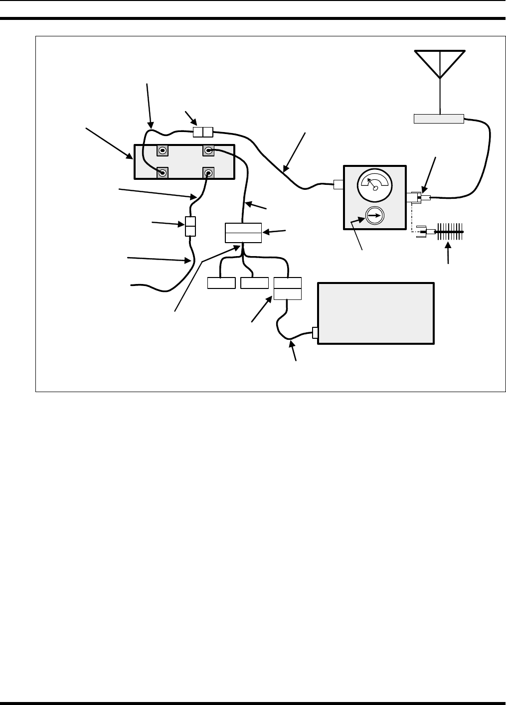
MM-007024-001
53
GPS ANTENNA
CONNECTION
NOT SHOWN. Wattmeter
N-Type to
TNC-Type Adaptor
TNC Male to N Female
Coaxial Jumper Cable
Slug
(25 W, 400–
1000 MHz) Dummy
Load
Antenna
IN
OUT
Radio’s Antenna
Cable
TNC Female
Connector
M7250
Mobile Radio
(Rear View)
Radio’s DC
Power Cable
Installation’s DC
Power Cable
From 13.8-Volt
Fused Power Source
3-Pin
Connectors
Radio’s I/O
Cable
44-Pin
Connectors
SERIALMODEMGPS
Personal Computer (PC)
Running Terminal
Application
COM1 Port
Serial Programming Cable
MAMROS0055 (or equivalent)
Full-Data I/O Option Cable
1000022242-0001
Or
Programming Option Cable
1000022242-0002
(Has the “SERIAL” connector only)
9-Pin
Connectors
No GPS/MODEM connection
required when programming.
Figure 16-1: Wattmeter Connections
3. If necessary, apply power to the radio and turn it on.
4. Set the radio to a test channel.
5. Position the wattmeter’s slug to measure forward RF output power. Rotate it if necessary. The arrow
on the face of the slug must point away from the radio and towards the dummy load for forward
power measurements.
6. Using Full-Data I/O Option Cable 1000022242-0001 and Serial Programming Cable MAMROS0055
(or equivalent), connect the radio’s serial port to the Personal Computer’s COM1 serial port. The
Serial Programming Cable is a standard modem-type serial interface cable.
7. At the computer, start the terminal application (e.g., HyperTerminal) and verify its configuration as
listed in Table 16-1.
8. Measure the radio’s RF output power by typing these commands. Send the commands in the order
presented. For the ^ symbol, type ^ (shifted 6 key on a standard keyboard). For letters, observe case
(e.g., type W, not w). Press the <Enter> key after typing each command:
^8 — puts the radio into 100% duty cycle test mode
^W — causes the radio to transmit
^X — causes the radio to terminate transmissions
atz9 — causes the radio to reboot
MM-007024-001
54
NOTE
Transmit only for as long as needed to take the measurement, then immediately disable the
transmission.
9. Compare the wattmeter reading with the target RF output power range of 11.8 – 20.0 watts.
10. Record the wattmeter reading for RF output power into the dummy load, or take remedial action and
measure the output again:
• If the wattmeter reading is within the range, record the measured value in the appropriate
space on the data collection form near the end of this manual.
• If the wattmeter reading is outside the range, verify the radio’s power supply voltage (i.e.,
battery voltage) is within the specified range, recheck all connections and measure the RF output
power again. If this fails to produce a reading within the range, replace it and repeat this
procedure.
16.4 TESTING WITH THE ANTENNA
The radio must be set to OTP mode (see Section 16.1) to perform the following tests. It is recommended
that a test channel be allocated for this testing; otherwise, interference with network users tuned to the
channel on which the radio is transmitting may occur. Also, observe the safety information presented
in Section 1 (page 5) of this manual!
1. Connect the radio’s antenna connector to the wattmeter and antenna as shown in Figure 16-1.
2. If necessary, apply power to the radio, turn it on, and set it to OTP mode.
3. Set the radio to a test channel, if available.
4. Position the wattmeter’s slug to measure forward RF output power. Rotate it if necessary. The arrow
on the face of the slug must point away from the radio and towards the antenna for forward power
measurements.
5. Using the Full-Data I/O Option Cable 1000022242-0001 and Serial Programming Cable
MAMROS0055 (or equivalent), connect the radio’s serial port to the Personal Computer’s COM1
serial port. The Serial Programming Cable is a standard modem-type serial interface cable.
6. At the computer, start the terminal application (e.g., HyperTerminal) and verify its configuration as
listed in Table 16-1.
7. Measure the radio’s forward RF output power into the antenna by typing these commands. Send the
commands in the order presented.
^8 — puts the radio into 100% duty cycle test mode
^W — causes the radio to transmit
^X — causes the radio to terminate transmissions
atz9 — causes the radio to reboot
NOTE
Transmit only for as long as needed to take the measurement, then immediately disable the
transmission.
8. Compare the wattmeter reading with the target RF output power range of 11.8 – 20.0 watts.
MM-007024-001
55
9. Record the wattmeter reading for forward power into the antenna, or take remedial action and
measure the output again.
• If the wattmeter reading is within the range, record the value in the appropriate space on the
data collection form near the end of this manual.
• If the wattmeter reading is outside the range, verify the radio’s power supply voltage (i.e.,
battery voltage) is within the specified range, recheck all connections, and measure the forward
power again. If this fails to produce a reading within the range, check all cabling and connections,
and repeat the testing procedure to this point. In the event the wattmeter reading still falls outside
the range, replace the antenna, make sure all connections are seated firmly, and repeat the testing
procedure.
10. Position the wattmeter’s slug to measure reverse (reflected) RF power from the antenna. The arrow
on the face of the slug must point away from the antenna and toward the radio to measure reverse
power.
11. Measure the reverse (reflected) RF power from the antenna by typing these commands:
^8 — puts the radio into 100% duty cycle test mode
^W — causes the radio to transmit
^X — causes the radio to terminate transmissions
atz9 — causes the radio to reboot
NOTE
Transmit only for as long as needed to take the measurement, then immediately disable the
transmission.
12. Compare the wattmeter reading with the RF power output range of 2 watts or less.
13. Record the wattmeter reading for reverse RF power from the antenna, or take remedial action and
measure the output again.
• If the wattmeter reading is within the range, record the value in the appropriate space on the
data collection form near the end of this manual.
• If the wattmeter reading is outside the range, make sure the antenna is consistent with the
specified frequency range of the radio. Recheck all antenna connections, and measure the reverse
power again. If this fails to produce a reading within the range, replace the antenna and repeat the
entire antenna test procedure. Any value exceeding the maximum allowable reflected power
value will result in a diminished RF output signal.
14. Disconnect the coaxial cable jumper and wattmeter.
15. Permanently connect the mobile antenna cable to the radio’s antenna cable by mating the two TNC
connectors together. Use two pairs of slip-jaw pliers to gently tighten this connection. Do not over
tighten and do not twist either cable.
NOTE
To prevent RF leakage and ensure peak performance, make sure the RF connectors are
tight, but do not over tighten so connector damage will not occur.

MM-007024-001
56
WARNING
Improper installation of the RF cables may lead not only to poor radio performance but
also to harmful exposure to RF electromagnetic energy.
16. Disconnect the computer’s COM1 serial port from the radio’s serial port.
Testing is complete. The radio is now ready for normal communications.
MM-007024-001
57
16.5 TEST PERFORMANCE DATA FORM
1. Enter the information requested on this data collection form. Clip this form and file it as a permanent record
of the tested performance of the installed Full-Duplex M7250.
Clip
Here
Company Performing Installation Technician Performing Test
Date of Test
(mm/dd/yyyy)
Mobile Radio
Serial Number Antenna Make and Model
Power Into a Dummy
Load
Watts
Forward Power With
Antenna Reflected Power
With Antenna
Watts
Watts

MM-007024-001
58
This page intentionally left blank

MM-007024-001
59
17 COMPLETE THE INSTALLATION
Double-check the following items before considering the installation completed:
• Verify all newly installed mechanical hardware is mounted securely and all respective mounting
hardware is tight.
• Verify all electrical interconnections are connected properly and the associated connector attachment
hardware is tight. Pay special attention to all RF antenna cables!
• Verify all related fuses are correctly installed and properly rated.
• Verify all electrical cables and wiring are tied, stowed, and protected so they are out of the way of
casual contact, away from sources of extreme heat, and wire chafing cannot occur. Pay special
attention to all RF antenna cables!
• To prevent fumes from entering the vehicle’s passenger compartment, seal the hole/grommet/wire
combination at the firewall with a silicon-based sealer.
• Verify all vehicle components are properly reinstalled such as kick panels, headliners, and seats.
• If the installation includes a separately-mounted on/off power switch for manually turning the radio
(and possibly others systems) on and off, verify it is labelled accordingly. For example: “Radio
ON/OFF.”
• Remove all tools and unused hardware from the vehicle.
• Verify the test performance data has been recorded on the data collection form shown in this manual.

MM-007024-001
60
18 WARRANTY
A. M/A-COM, Inc. (hereinafter "Seller") warrants to the original purchaser for use (hereinafter "Buyer")
that Equipment manufactured by or for the Seller shall be free from defects in material and
workmanship, and shall conform to its published specifications. With respect to all non-M/A-COM
Equipment, Seller gives no warranty, and only the warranty, if any, given by the manufacturer shall
apply. Rechargeable batteries are excluded from this warranty but are warranted under a separate
Rechargeable Battery Warranty (ECR-7048).
B. Seller’s obligations set forth in Paragraph C below shall apply only to failures to meet the above
warranties occurring within the following periods of time from date of sale to the Buyer and are
conditioned on Buyer’s giving written notice to Seller within thirty (30) days of such occurrence:
1. for fuses and non-rechargeable batteries, operable on arrival only.
2. for parts and accessories (except as noted in B.1) sold by Seller’s Service Parts
Operation, ninety (90) days.
3. for PANTHER™ Series hand-portable and mobile radios, two (2) years.
4. for all other equipment of Seller’s manufacture, one (1) year.
C. If any Equipment fails to meet the foregoing warranties, Seller shall correct the failure at its option (i)
by repairing any defective or damaged part or parts thereof, (ii) by making available at Seller’s factory
any necessary repaired or replacement parts, or (iii) by replacing the failed Equipment with equivalent
new or refurbished Equipment. Any repaired or replacement part furnished hereunder shall be
warranted for the remainder of the warranty period of the Equipment in which it is installed. Where
such failure cannot be corrected by Seller’s reasonable efforts, the parties will negotiate an equitable
adjustment in price. Labor to perform warranty service will be provided at no charge during the
warranty period only for the Equipment covered under Paragraph B.3 and B.4. To be eligible for no-
charge labor, service must be performed at a M/A-COM factory, by an Authorized Service Center
(ASC) or other Servicer approved for these purposes either at its place of business during normal
business hours, for mobile or personal equipment, or at the Buyer’s location, for fixed location
equipment. Service on fixed location equipment more than thirty (30) miles from the Service Center or
other approved Servicer’s place of business will include a charge for transportation.
D. Seller’s obligations under Paragraph C shall not apply to any Equipment, or part thereof, which (i) has
been modified or otherwise altered other than pursuant to Seller’s written instructions or written
approval or, (ii) is normally consumed in operation or, (iii) has a normal life inherently shorter than the
warranty periods specified in Paragraph B, or (iv) is not properly stored, installed, used, maintained or
repaired, or, (v) has been subjected to any other kind of misuse or detrimental exposure, or has been
involved in an accident.
E. The preceding paragraphs set forth the exclusive remedies for claims based upon defects in or
nonconformity of the Equipment, whether the claim is in contract, warranty, tort (including
negligence), strict liability or otherwise, and however instituted. Upon the expiration of the warranty
period, all such liability shall terminate. The foregoing warranties are exclusive and in lieu of all other
warranties, whether oral, written, expressed, implied or statutory. NO IMPLIED OR STATUTORY
WARRANTIES OF MERCHANTABILITY OR FITNESS FOR PARTICULAR PURPOSE SHALL
APPLY. IN NO EVENT SHALL THE SELLER BE LIABLE FOR ANY INCIDENTAL,
CONSEQUENTIAL, SPECIAL, INDIRECT OR EXEMPLARY DAMAGES.
This warranty applies only within the United States.
M/A-COM, Inc. M/A-COM, Inc.
1011 Pawtucket Blvd. 221 Jefferson Ridge Parkway
Lowell, MA 01853 Lynchburg, VA 24501
1-877- 1-800-528-7711
ECR-7047C
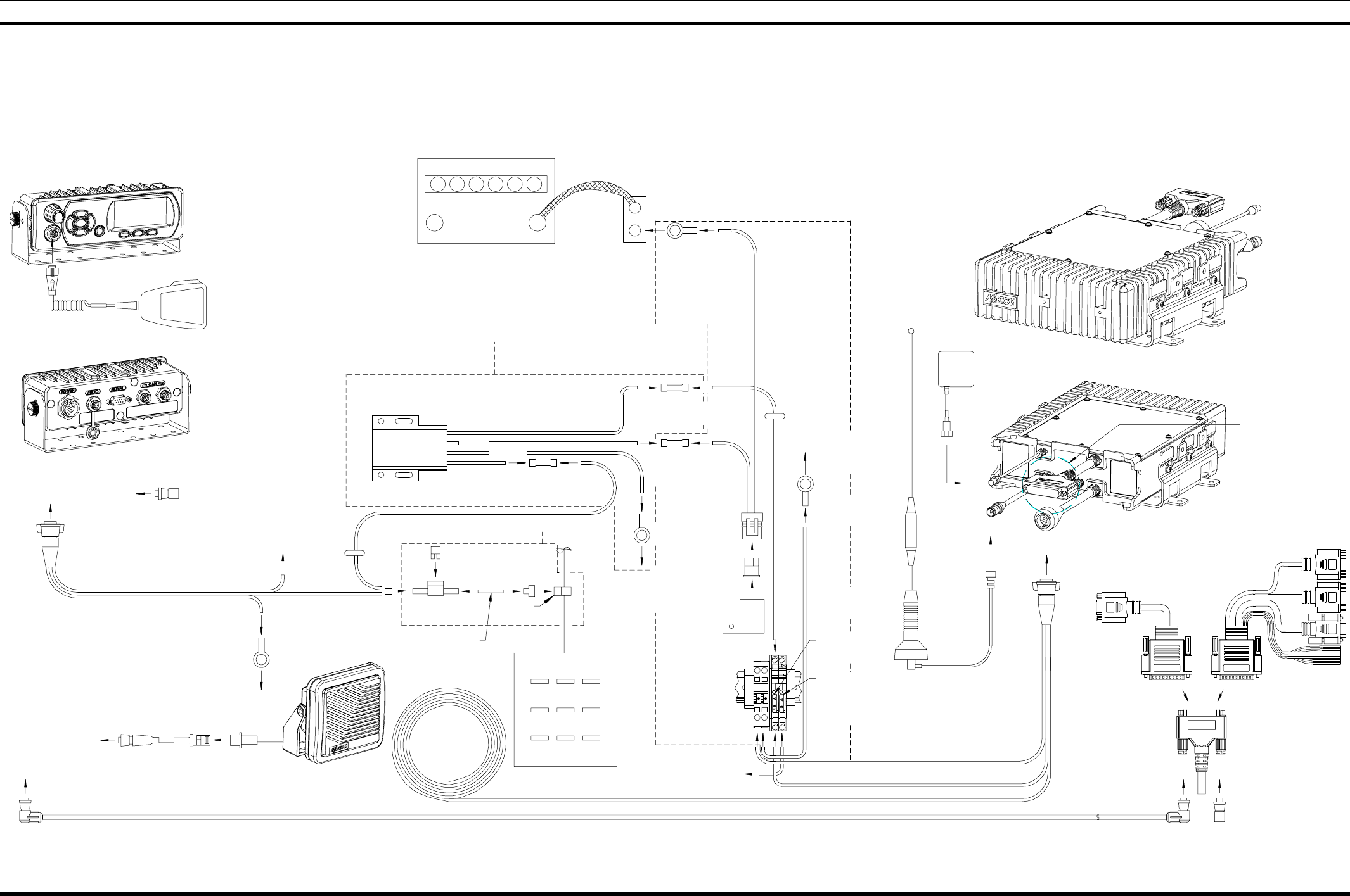
MM-007024-001
61
19 WIRING DIAGRAM: MOBILE RADIO WITH CH-103 CONTROL HEAD
FS24473 FUSE KIT
MAMV-SU5B
CH-103 RELAY KIT
I/O
#12-10AWG
MOISTURE RESISTANT
BUTT SPLICE
5A ATC FUSE,
FUSE HOLDER,
AND JUMPER
(FROM FS23058
FUSE KIT)
15A ATC FUSE
(FROM FS23057
FUSE KIT)
MACDOS0010
CAN TERMINATOR
OR
#12-10AWG
MOISTURE RESISTANT
BUTT SPLICE
3/8"
RING TERMINAL
CONNECT TO
VEHICLE CHASSIS
GND
#10 AWG,
BLACK, 1 FT
3/8 I.D.
RING TERMINAL
WAGO FUSE
BLOCK
(in trunk)
T-TAP
DISCONNECT
(through
grommet
in firewall)
(through
grommet in
firewall)
VEHICLE
DISTRIBUTION
BLOCK (IF AVAILABLE)
3/8"
RING TERMINAL
ATC FUSE
HOLDER
30A FUSE
1000003678
BASE BRACKET
(SHOWN WITH HARDWARE)
#10 AWG,
RED, 20 FT
ANTENNA
MAMV-AN3N
RF ANTENNA
(OPTIONAL)
MAMV-AN3L
GPS ANTENNA KIT
(OPTIONAL)
(Short as possible)
MAMROS0075-N1210
DC POWER CABLE
D.C. POWER
POS
NEG
-+
VEHICLE BATTERY
WHITE
TO
CH AUDIO
TO
CH CAN
TO
CH CAN
AJ03067
CONTROL HEAD MOUNTING BRACKET
(SHOWN WITH HARDWARE)
(SHORT SECTION OF
WIRE CUT FROM WHITE
WIRE FOR SPLICING)
FS23057
FUSE KIT
WHITE
RED
BLACK
(WHITE WIRE, LABELED
AND COILED NEAR FUSE BOX)
IGNITION
SENSE WIRE
1000005812-0001
SPEAKER CABLE
MACDOS0006-RR030 CAN CABLE
MACDOS0010
CAN TERMINATOR
MAMV-MC7W
MICROPHONE,
NOISE-CANCELING
LS102824V10
EXTERNAL SPEAKER
(MAMROS0035 WITH CABLE)
TO
CH POWER
MAMROS0075-N1210
DC POWER CABLE
MACDOS0003
(MAMV-CP9D)
CONTROL HEAD CH-103
CONNECT TO
VEHICLE CHASSIS
GND
3/8 I.D.
RING TERMINAL
BLACK
QUICK
CONNECT
TAB
ATM FUSE
HOLDER
2A FUSE
VEHICLE FUSE BLOCK
RED
RU25011-0001
(MAMV-FDLXX)
TRUNK-MOUNT
FULL DUPLEX RADIO
MAMROS0088
TIME-DELAY RELAY
#20-18AWG
BUTT SPLICE
YELLOW
BLACK
WHITE
RED
CONNECT TO
VEHICLE CHASSIS
GND
#18 AWG, WHITE
(not supplied)
TO WAGO
FUSE BLOCK
RED WIRE FROM
CONTROL HEAD
SEE VIEW 'A' FOR I/O
CONNECTION DETAILS
VIEW A
GPS
I/O
1000022242-0001
FULL I/O OPTION
CABLE
1000022242-0002
PROGRAMMING OPTION
CABLE

MM-007024-001
Wiring Diagram Inside
(With CH103)
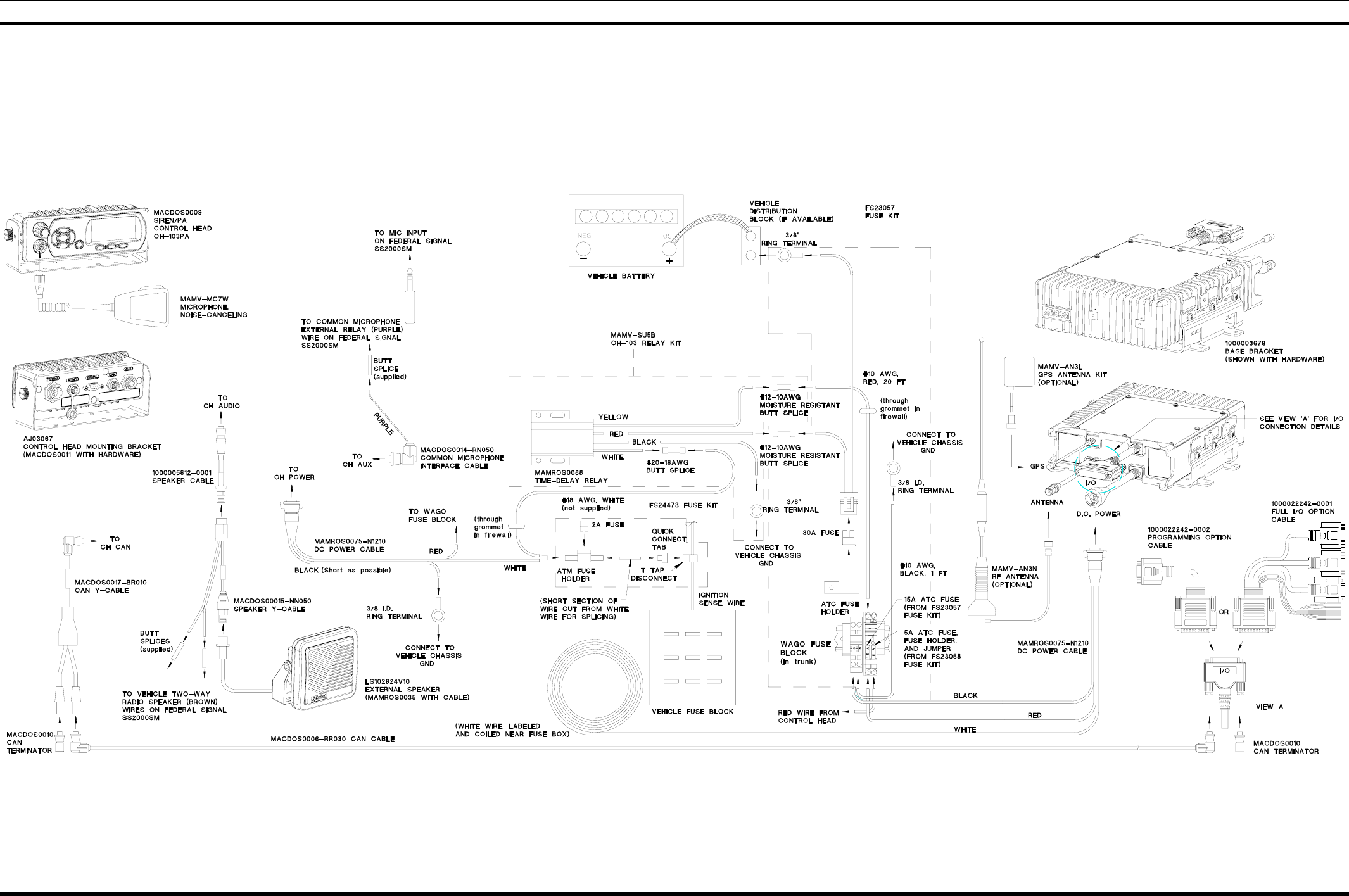
MM-007024-001
63
20 WIRING DIAGRAM: MOBILE RADIO WITH CH-103PA CONTROL HEAD
RU25011-0001
(MAMV-FDLXX)
TRUNK-MOUNT
FULL-DUPLEX RADIO

M/A-COM Wireless Systems
221 Jefferson Ridge Parkway
Lynchburg, Virginia 24501
(Outside the USA, 434-385-2400) Toll Free 800-528-7711
www.macom-wireless.com Printed in U.S.A.
Wiring Diagram Inside
(With CH-103PA)