HARRIS M7200 M7200 700/800 MHz Mobile Radio User Manual Manual 2
Harris Corporation M7200 700/800 MHz Mobile Radio Manual 2
HARRIS >
Contents
Manual 2

Installation and Product Safety Manual
MM-011712-001
Mar/07
CS-7200, SP-103, and TRCM-103
Control Station, Desk Set, and
Tone Remote Control Module
MM-011712-001
2
MANUAL REVISION HISTORY
REV. DATE REASON FOR CHANGE
— Mar/07 Original release.
M/A-COM Technical Publications would particularly appreciate feedback on any errors found in this document and
suggestions on how the document could be improved. Submit your comments and suggestions to:
Wireless Systems Business Unit
M/A-COM, Inc. or fax your comments to: 1-434-455-6851
Technical Publications
221 Jefferson Ridge Parkway or e-mail us at: techpubs@tycoelectronics.com
Lynchburg, VA 24501
CREDITS
M/A-COM, Inc. and/or Tyco Electronics may have patents, patent applications, trademarks, copyrights, or other intellectual
property rights covering subject matter in this document. Except as expressly provided in any written license agreement from
M/A-COM, the furnishing of this document does not give you any license to these patents, trademarks, copyrights, or other
intellectual property.
The software contained in this device is copyrighted by M/A-COM, Inc. Unpublished rights are reserved under the copyright
laws of the United States.
This device made under license under one or more of the following U.S. Patents: 4,590,473; 4,636,791; 5,148,482;
5,185,796; 5,271,017; 5,377,229; 4,716,407; 4,972,460; 5,502,767; 5,146,497; 5,164,986; 5,185,795
The voice coding technology embodied in this product is protected by intellectual property rights including patent rights,
copyrights, and trade secrets of Digital Voice Systems, Inc. The user of this technology is explicitly prohibited from
attempting to decompile, reverse engineer, or disassemble the Object Code, or in any other way convert the Object Code into
human-readable form.
OpenSky® is a registered trademark of M/A-COM, Inc.
Microsoft® and Windows® are registered trademarks of Microsoft Corporation, Zetron® is a registered trademark of Zetron,
Inc., GAI-TRONICS® is a registered trademark of GAI-Tronics Corporation, and WAGO® is a registered trademark of Wago
Corporation.
NOTICE!
This manual covers M/A-COM products manufactured and sold by M/A-COM, Inc.
Repairs to this equipment should be made only by an authorized service technician or facility designated by the supplier. Any
repairs, alterations or substitution of recommended parts made by the user to this equipment not approved by the
manufacturer could void the user’s authority to operate the equipment in addition to the manufacturer’s warranty.
M/A-COM recommends the buyer use only a M/A-COM authorized representative to install and service this product.
The warranties provided to buyer under the terms of sale shall be null and void if this product is installed or serviced
improperly and M/A-COM shall have no further obligation to the buyer for any damage caused to the product or to any
person or personal property.
This product conforms to the European Union WEEE Directive 2002/96/EC. Do not dispose of this
product in a public landfill. Take it to a recycling center at the end of its life.
This manual is published by M/A-COM, Inc. without any warranty. Improvements and changes to this manual necessitated by typographical errors,
inaccuracies of current information, or improvements to programs and/or equipment, may be made by M/A-COM, Inc., at any time and without notice. Such
changes will be incorporated into new editions of this manual. No part of this manual may be reproduced or transmitted in any form or by any means,
electronic or mechanical, including photocopying and recording, for any purpose, without the express written permission of M/A-COM, Inc.
Copyright© 2007, M/A-COM, Inc. All rights reserved.

MM-011712-001
3
TABLE OF CONTENTS
Page
1 SAFETY INFORMATION ..........................................................................................................................5
1.1 SAFETY SYMBOLS........................................................................................................................ 5
1.2 IMPORTANT SAFETY INSTRUCTIONS......................................................................................5
1.3 FCC REGULATIONS ......................................................................................................................6
2 INTRODUCTION......................................................................................................................................... 8
2.1 CS-7200 CONTROL STATION.......................................................................................................8
2.1.1 Voice Operation..................................................................................................................8
2.1.2 Data Operation...................................................................................................................9
2.1.3 Intercom Operation ............................................................................................................9
2.2 SP-103 DESK SET ...........................................................................................................................9
2.3 TRCM-103 TONE REMOTE CONTROL MODULE......................................................................9
2.4 RELATED DOCUMENTATION.....................................................................................................9
2.5 TECHNICAL ASSISTANCE........................................................................................................... 9
3 UNPACKING AND CHECKING EQUIPMENT....................................................................................10
3.1 MATERIALS..................................................................................................................................10
3.2 MATERIAL INSPECTION............................................................................................................ 10
4 INSTALLATION ........................................................................................................................................12
4.1 REQUIRED TOOLS AND CONFIGURATION EQUIPMENT ....................................................12
4.1.1 Tools Required..................................................................................................................12
4.1.2 Equipment Required for CS-7200 Configuration.............................................................12
4.2 LOCATING COMPONENTS ........................................................................................................12
4.3 CS-7200 INSTALLATION ............................................................................................................13
4.3.1 Rack-Mount and Desktop Mounting.................................................................................13
4.3.2 AC Power Connection ......................................................................................................14
4.3.3 Fuse Replacement.............................................................................................................14
4.4 ANTENNA INSTALLATION .......................................................................................................15
4.4.1 General Information.........................................................................................................15
4.4.2 Coaxial Cable...................................................................................................................15
4.5 GROUNDING AND LIGHTNING PROTECTION FOR THE CS-7200.......................................16
4.6 SP-103 DESK SET CONNECTION...............................................................................................17
4.7 CONNECTING TO A TONE REMOTE CONTROLLER (OPTIONAL)...................................... 18
4.7.1 DIP Switch and Jumper Settings ......................................................................................18
4.7.2 Installation Configurations...............................................................................................21
4.7.3 Installing the TRCM-103 into the CS-7200......................................................................23
4.7.4 Connecting to the TRC .....................................................................................................24
4.8 CONNECTING THE CAN CABLE...............................................................................................26
4.8.1 SP-103 CAN Connections.................................................................................................26
4.8.2 Connecting via the CAN Bus Extender (Fiber Optic Cable Installations) .......................30
4.8.3 TRCM-103 CAN Connections...........................................................................................30
5 POWER-UP PROCEDURE.......................................................................................................................31
6 CHANGING OPERATING MODE.......................................................................................................... 32
6.1 SP-103 METHOD...........................................................................................................................32
6.2 PC RUNNING A TERMINAL APPLICATION METHOD........................................................... 32
7 LINE-LEVEL ALIGNMENT FOR A TRCM-103 EQUIPPED STATION ..........................................34
7.1 TRCM-103 TO TONE REMOTE CONTROLLER ........................................................................34
7.2 TONE REMOTE CONTROLLER TO TRCM-103 ........................................................................35
8 PROGRAMMING TONE FUNCTIONS TO MATCH TRC BUTTONS (OPTIONAL).....................36
8.1 EMERGENCY START ..................................................................................................................37

MM-011712-001
4
TABLE OF CONTENTS
Page
8.2 EMERGENCY STOP .....................................................................................................................37
8.3 PRESET ..........................................................................................................................................38
8.4 SAVING NEW PROGRAMMING.................................................................................................38
9 ANTENNA PERFORMANCE TESTS......................................................................................................39
9.1 REQUIRED TEST EQUIPMENT ..................................................................................................40
9.2 TRANSMITTING INTO A DUMMY LOAD.................................................................................40
9.3 TRANSMITTING INTO THE ANTENNA ....................................................................................41
9.4 TEST PERFORMANCE DATA FORM .........................................................................................43
10 COMPLETE THE INSTALLATION .......................................................................................................44
11 WARRANTY ...............................................................................................................................................45
FIGURES
Figure 4-1: CS-7200 Front Panel.........................................................................................................13
Figure 4-2: CS-7200 Rear Panel..........................................................................................................14
Figure 4-3: CS-7200 Fuse Replacement (Rear Panel Views) .............................................................15
Figure 4-4: SP-103 Front and Rear Panels ..........................................................................................17
Figure 4-5: DIP Switch and Jumper Configuration Label (Located on Bottom of TRCM-103) ........19
Figure 4-6: TRCM-103 Jumper and Switch Settings ..........................................................................20
Figure 4-7: TRCM-103 Configured as an Endpoint and Interfaced to One TRC ...............................21
Figure 4-8: TRCM-103 Configured as an Endpoint and Interfaced to Multiple Paralleled TRCs......22
Figure 4-9: TRCM-103 in the Middle of a Chain and Interfaced to Multiple Paralleled TRCs..........22
Figure 4-10: TRCM-103 Installation into CS-7200 and its External Interfaces..................................23
Figure 4-11: Connecting CS-7200 to the SP-103 via In-Wall/Plenum CAN Cable Connections.......28
Figure 4-12: Dimensions for Stripping 3-Wire CAN Cables ..............................................................29
Figure 4-13: 3-Position Terminal Strip Connections...........................................................................30
Figure 7-1: TRCM-103 Line-Level Adjustments................................................................................34
TABLES
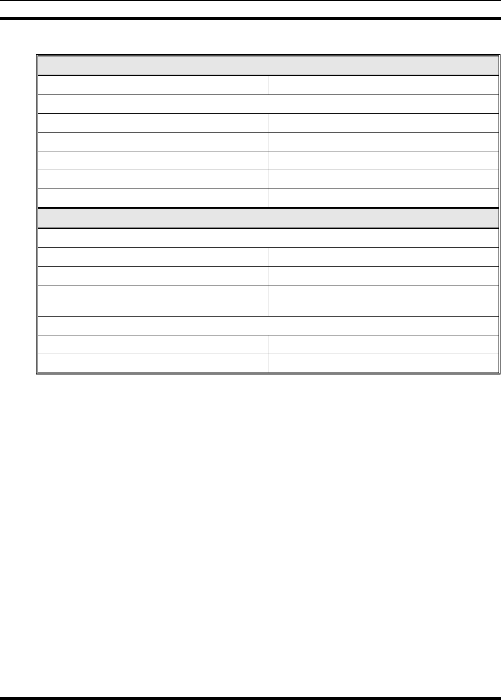
Table 3-1: CS-7200 Accessories .........................................................................................................11
Table 4-1: TRCM-103 Audio Interface Pin-Out (RJ-11 Modular Jack Labeled “AUDIO”) ..............24
Table 4-2: TRCM-103 to Zetron Model 280 2-Wire Line Interface Connections .............................25
Table 4-3: TRCM-103 to Zetron Model 280 4-Wire Line Interface Connections .............................25
Table 4-4: TRCM-103 to GAI-TRONICS Model ITR2000A 2-Wire Line Interface
Connections.......................................................................................................................25
Table 4-5: TRCM-103 to GAI-TRONICS Model ITR2000A 4-Wire Line Interface
Connections.......................................................................................................................26
Table 6-1: HyperTerminal Settings Required for Changing Operating Mode ....................................33
Table 8-1: Function Tone Frequencies................................................................................................36
Table 9-1: Required Test Equipment...................................................................................................40
MM-011712-001
5
1 SAFETY INFORMATION
1.1 SAFETY SYMBOLS
The following conventions are used throughout this manual to alert the user to general safety precautions
that must be observed during all phases of operation, service, and repair of this product. Failure to comply
with these precautions or with specific warnings elsewhere violates safety standards of design,
manufacture, and intended use of the product. M/A-COM, Inc. assumes no liability for the customer's
failure to comply with these standards.
The WARNING symbol calls attention to a procedure, practice, or the like, which,
if not correctly performed or adhered to, could result in personal injury. Do not
proceed beyond a WARNING symbol until the conditions identified are fully
understood or met.
CAUTION
The CAUTION symbol calls attention to an operating procedure, practice, or the like,
which, if not performed correctly or adhered to, could result in damage to the
equipment or severely degrade equipment performance.
The NOTE symbol calls attention to supplemental information, which may improve
system performance or clarify a process or procedure.
The ESD symbol calls attention to procedures, practices, or the like, which could
expose equipment to the effects of Electro-Static Discharge. Proper precautions must be
taken to prevent ESD when handling circuit boards or modules.
The electrical hazard symbol is a WARNING indicating there may be an electrical
shock hazard present.
1.2 IMPORTANT SAFETY INSTRUCTIONS
1. Read these instructions.
2. Keep these instructions.
3. Heed all warnings.
4. Follow all instructions.
5. Do not use this apparatus near water.
6. Clean only with dry cloth.
7. Do not block any ventilation openings. Install in accordance with the manufacturer’s instructions.
MM-011712-001
6
8. Do not install near any heat sources such as radiators, heat registers, stoves, or other apparatus
(including amplifiers) that produce heat.
9. Do not defeat the safety purpose of the polarized or grounding-type plug. A polarized plug has two
blades with one wider than the other. A grounding type plug has two blades and a third grounding
prong. The wide blade or the third prong is provided for your safety. If the provided plug does not fit
into your outlet, consult an electrician for replacement of the obsolete outlet.
10. Protect the power cord from being walked on or pinched particularly at plugs, convenience
receptacles, and the point where they exit from the apparatus.
11. Only use attachments/accessories specified by the manufacturer.
12. Use only with the cart, stand, tripod, bracket, or table specified by the manufacturer, or sold with the
apparatus. When a cart is used, use caution when moving the cart/apparatus combination to avoid
injury from tip-over.
13. Unplug this apparatus during lightning storms or when unused for long periods of time.
14. Refer all servicing to qualified service personnel. Servicing is required when the apparatus has been
damaged in any way, such as power-supply cord or plug is damaged, liquid has been spilled or
objects have fallen into the apparatus, the apparatus has been exposed to rain or moisture, does not
operate normally, or has been dropped.
15. Warning: The lightning bolt signifies an alert to the user of the presence of un-insulated “dangerous
voltage” within the product’s enclosure that may be of significant magnitude to constitute a risk of
electric shock to persons.
16. Warning: The exclamation point alerts the user to the presence of important operation and
maintenance (service) instructions in the literature accompanying the product.
17. Outdoor Use Warning: To reduce the risk of Fire or Electric Shock, Do Not Expose This Apparatus
to Rain or Moisture.
18. Wet Location Warning: Apparatus shall not be exposed to dripping or splashing and no objects
filled with liquids, such as vases, shall be placed on the apparatus.
1.3 FCC REGULATIONS
Use, installation and service of this equipment as summarized within this Manual will ensure the safe
performance of this equipment and will result in user exposure substantially below FCC recommended
limits for human exposure to Radio Frequency electromagnetic energy.
These devices comply with Part 15 of the FCC Rules. Operation is subject to the following two
conditions: (1) the device may not cause harmful interference; and (2) the device must accept any
interference received, including interference that may cause undesired operation.

MM-011712-001
7
These devices are not required to comply with the FCC RF exposure limits for Uncontrolled Exposure
(General Population) and Occupational Exposure, because it is assumed that neither uncontrolled nor
occupational exposure is applicable in the general installation configuration. The CS-7200 must be
disabled before maintenance to the antenna is attempted.
The Federal Communications Commission (FCC) requires the user to obtain a station license for this
radio equipment before operation.
FCC regulations state that the frequency, deviation, and power of the radio transmitter must be
maintained within specific limits. It is recommended, therefore, that these three parameters be checked
prior to placing the station in service.

MM-011712-001
8
2 INTRODUCTION
2.1 CS-7200 CONTROL STATION
The CS-7200 Control Station is a high-performance full-duplex dual-band digital radio control station. It
can operate on 700 MHz or 800 MHz OpenSky trunked radio networks using the OpenSky Trunking
Protocol (OTP). In the future, the station will also operate on 800 MHz Enhanced Digital Access
Communications System (EDACS) trunked radio networks, and 800 MHz APCO Project 25 phase I
compliant Common Air Interface (P25 CAI) trunked radio networks. Other future operating modes
include talk-around communications in accordance with the APCO Project 25 phase I standard, and
conventional FM repeater-based and FM talk-around voice communications in accordance with the
TIA/EIA-603 conventional land-mobile radio standard.
The CS-7200 is typically used for dispatch communications via a remotely-connected SP-103 Desk Set or
via a separately-supplied Tone Remote Controller (TRC). The CS-7200 is shown in Figure 4-1 and
Figure 4-2 on page 14, and the SP-103 is shown in Figure 4-4 on page 17. The CS-7200-to-SP-103
interconnection is performed via a Controller Area Network (CAN) link connections. The CAN link may
also employ an optional fiber optic-based CAN Bus Extender for increased distance separation between
the CS-7200 and the SP-103. CS-7200-to-TRC interconnection is performed via 2-wire or 4-wire line
audio connections.
The CS-7200 can operate as full-duplex radio frequency transceiver during data communications. Typical
full-duplex RF transmit output power is 10 watts. Typical half-duplex RF transmit output power is
15 watts.
700 MHz operating bands of the station include the two 3 MHz wide repeater output bands from 764 to
767 MHz and 773 to 776 MHz, and the two 3 MHz wide repeater input bands from 794 to 797 MHz and
803 to 806 MHz. The station can operate only on the narrowband channels within these bands. Transmit
output power is limited to 300 milliwatts on interoperability channels.
800 MHz operating bands of the station include the Specialized Mobile Radio (SMR) and the National
Public Safety Planning Advisory Committee (NPSPAC) radio frequency channels. This includes the 806
to 825 MHz repeater input band, and the 851 to 869 MHz band used for repeater output and talk-around
communications. These bands provide a total of over 830 possible channels spread over the
806 to 824 MHz mobile transmission and 851 to 869 MHz mobile reception bands.
The CS-7200 uses Time Division Multiple Access (TDMA) technology to allow multiple users to share a
single RF channel. In addition, a single 25 kHz RF channel can support simultaneous digital voice and
data communications.
The CS-7200 provides voice and data services in a dispatch operation. Voice operation is provided using
the SP-103 Desk Set or third-party Tone Remote Controllers (TRCs) interfaced via the TRCM-103. The
TRCM-103 is a field-installable option that is required when interconnecting the CS-7200 to one or more
TRCs. For data transfers, the CS-7200 and the SP-103 are equipped with an industry standard
TIA/EIA-232 serial interface port for connecting optional equipment such as a laptop PC or third-party
display or key-entry device. OpenSky works seamlessly with equipment from popular manufacturers and
off-the-shelf applications through standard User Datagram Protocol over Internet Protocol (UDP/IP) data
packet transfers, providing simple “plug and play” connectivity.
2.1.1 Voice Operation
The voice path operates like a traditional dispatch radio, with a microphone to transmit (push-to-talk) and
a speaker to receive. In OpenSky Trunked Protocol (OTP), there is no separate voice and data path—all
transmitted information is digital.

MM-011712-001
9
2.1.2 Data Operation
Data operation requires the connection of a laptop PC or third-party display device. OpenSky works
through standard UDP/IP data packet transfers. The data path operates similarly to the voice path, with a
few differences. All external data information in and out of the radio uses the TIA/EIA-232 serial port
connection.
2.1.3 Intercom Operation
The optional intercom function allows communication between SP-103 Desk Set operators. Even when it
is activated, incoming network radio calls are still routed to the speaker in the SP-103 Desk Set. In other
words, radio calls are not muted when the Desk Set-to-Desk Set intercom function is active.
2.2 SP-103 DESK SET
The SP-103 Desk Set is part of the OpenSky suite of mobile radio products delivering high capacity end-
to-end digital communications. It provides remote access for voice, data, and control of the CS-7200
Control Station. See Figure 4-4 on page 17.
The SP-103 supports voice access to the radio via PTT (push-to-talk) microphones or headset
microphones/speaker devices. The SP-103 also provides an interface for a footswitch PTT in order to
support microphones/headsets that do not contain integral PTT switches.
The SP-103 has a 3 x 4 DTMF (Dual-Tone Multi-Frequency) keypad for log-on and selective calling
functions. The SP-103 contains an internal 10-Watt speaker and it is equipped with an external speaker
jack for connection of an external 10-Watt speaker. The serial port can be used for data operation.
2.3 TRCM-103 TONE REMOTE CONTROL MODULE
The TRCM-103 operates within the OpenSky network as part of a dispatch center in conjunction with the
CS-7200 Control Station and one or more third-party Tone Remote Controllers (TRCs). It provides
remote voice and control communication paths for the CS-7200. The TRCM-103 is a depot or field-
installed option. It mounts into a slot at the back of the CS-7200. It automatically detects one of five alert
tones and sixteen function tones with a 26 dB dynamic range. The audio interface utilizes a standard
RJ-11 port and is configurable for 2-wire half-duplex or 4-wire full-duplex operation. The audio
termination is selectable for either low impedance (600 ohms) or high impedance (6k ohms). These
features allow for easy integration with existing TRCs.
2.4 RELATED DOCUMENTATION
The following document contains additional information on the CS-7200, SP-103, and TRCM-103. This
document should be available for reference during the installation of this equipment.
• CS-7200, SP-103, and TRCM-103 Operator’s Manual MM-011709-001
2.5 TECHNICAL ASSISTANCE
Should the CS-7200, SP-103, or TRCM-103 require repair, or if you have questions or concerns about the
installation of this equipment, contact M/A-COM’s Technical Assistance Center (TAC) using the
following telephone numbers or email address:
• U.S. and Canada: 1-800-528-7711 (toll free)
• International: 1-434-385-2400
• Fax: 1-434-455-6712
• Email: tac@tycoelectronics.com
MM-011712-001
10
3 UNPACKING AND CHECKING EQUIPMENT
3.1 MATERIALS
The CS-7200 Control Station, part number CT-011355-001, includes an AC Power Cord to connect it to
standard AC power (120 Vac, 60 Hz). No installation kit is available, as every installation is custom. The
CS-7200 is generally used in conjunction with the SP-103 Desk Set, both of which have accessories that
can be installed. Table 3-1 lists available accessories.
The CS-7200 must not be powered up unless an antenna is installed and
connected. An antenna and its cabling must be purchased separately. Antennas
and coaxial cables are typically custom to the installation site. Have a site survey
performed to identify an appropriate antenna and antenna feedline requirements.
3.2 MATERIAL INSPECTION
CAUTION
After removal from the carton, examine the components and installation items for
broken, damaged, loose or missing parts. If any are noted, contact M/A-COM’s
Technical Assistance Center (see page 9) immediately to discuss and arrange for the
return of the equipment to M/A-COM for replacement. Any unauthorized attempts to
repair or modify this equipment will void the warranty and could create a safety
hazard.
Upon removing items from the carton and verifying all equipment is accounted for, proceed with the
installation.
CAUTION
Mounting of the CS-7200, SP-103, TRCM-103 and/or antenna in ways other than
those described can adversely affect performance, violate FCC rules on RF exposure,
and even damage the unit, posing a potential safety hazard.

MM-011712-001
11
Table 3-1: CS-7200 Accessories
PART NUMBER DESCRIPTION
MACDOS0007 TRCM-103 Tone Remote Control Module
MACDOS0008 SP-103 Desk Set
MACTOS0002 Controller, Tone Remote: M280, 115 Vac (Zetron)
MACTOS0003-FSDHA Controller, Tone Remote: TR10-16F-FD (CPI)
MACTOS0004 Controller, Tone Remote: ITR2000A (GAI-Tronics)
MACDOS0016 Cable Kit, Siren/PA Cables for SP-103
MC103334V20 Microphone, Noise-Canceling with Straight Connector; 14-pin
Alden type (See footnote 1)
344A4678P1 Microphone Hanger Kit (Includes hanger and two #8 x ¾-inch
self-threading screws)
MAMROS0072 Microphone Head, Desktop with PTT button
MACDOS0013-SN004 Speaker, External Kit: for SP-103 with Straight Connector
MACDOS0013-SR004 Speaker, External Kit: for SP-103, with Right-Angle Connector
MAMROS0093 Antenna, 800 MHz 6-element Yagi with 8 dBd Gain (Includes
U-bolt mounting hardware.)
TBD2 Antenna, 700 MHz 6-element Yagi with 8 dBd Gain (Includes
U-bolt mounting hardware.)
MAMROS0094 Antenna Mounting Kit, Universal Mount for Yagi Antenna
MAMROS0095 Cable, Coax: Antenna Jumper Kit
IS-CT50HN-MA Lightning Protection Device, 800 to 900 MHz
CA-009562-0R6 Cable, CAN; 0.6 feet, Black, Right-Angle-to-Straight Connectors
(for TRCM-103 only)
CA-009562-006 Cable, CAN; 6 feet, Black, Right-Angle-to-Straight Connectors
CA-009562-030 Cable, CAN; 30 feet, Black, Right-Angle-to-Straight Connectors
CA-009562-090 Cable, CAN; 90 feet, Black, Right-Angle-to-Straight Connectors
CA-009562-250 Cable, CAN; 250 feet, Black, Right-Angle-to-Straight Connectors
CA-011344 CAN Y-Cable, Black, Right-Angle Connector-to-Two Straight
Connectors
MAA7-NSU5C Kit, CAN Bus Extender (Includes CAN Bus Extender MD-008577
and AC Wall Power Supply.)
MAMROS0055 TIA/EIA-232 Serial Data Cable, 6-foot
1 Microphone MC103334V20 replaced Microphone Head MAMROS0036 & Microphone Cable Assembly MAMROS0038.
MM-011712-001
12
4 INSTALLATION
All equipment must be installed by an RF equipment installation professional.
Prior to installation, ensure that the CS-7200 has been configured for customer usage
such as channels and personality.
4.1 REQUIRED TOOLS AND CONFIGURATION EQUIPMENT
4.1.1 Tools Required
The following is a list of tools required to complete a standard installation:
• Non-insulated crimp tool with 0.128-inch and 0.429-inch dies;
• Phillips head screwdrivers, sizes #1 and #2;
• Flat head screwdrivers, sizes #1 and #2;
• Slip-jaw pliers;
• Various fasteners; and,
• Wire Strippers for 22-AWG and 14-AWG wire (required only for TRCM-103 installation).
If a Tone Remote Controller (TRC) will be connected to the CS-7200 via a TRCM-103 Tone Remote
Control Module, see the installation materials list on page 28.
4.1.2 Equipment Required for CS-7200 Configuration
The following is a list of additional equipment needed to configure the CS-7200:
• Personal Computer (PC) with an available serial communication port and running Microsoft
Windows operating system software and a terminal application software program such as Windows
HyperTerminal (see Table 6-1 on page 33 for settings);
• TIA/EIA-232 Serial Cable (MAMROS0055 or equivalent);
• For TRCM-103 option only: An SP-103 Desk Set (MACDOS0008) to set up function tones; and,
• See Table 9-1 on page 40 for a list of test equipment required to perform antenna tests procedures.
Additional equipment may be needed to install any tone remote controllers connected to the CS-7200 (via
a TRCM-103). Consult with the manufacturer’s recommendations as required.
4.2 LOCATING COMPONENTS
Plan the mounting locations of all components (CS-7200, antenna, and cables) and determine the routes
for all wiring and cables. Consider also the connection of the SP-103 and/or TRCM-103 for planning
purposes. Follow all manufacturer requirements and guidelines for the location of components.
MM-011712-001
13
For installations with the SP-103 Desk Set which require connection through the CAN
(Controller Area Network) digital interface, pay particular attention to the routing of
CAN cable in the facility. It may be necessary to use plenum-rated cable for in-
building installations. Refer to section 4.8 that begins on page 26 and/or consult with
TAC to identify the proper cabling.
CAUTION
All cables should be installed with a service loop at each end. During the installation,
do NOT bend any cable at a severe angle near a connector. When the installation is
complete, verify no cable is under any tension. Failure to do so may lead to damaged
cables, causing intermittent operation, or complete equipment failure.
Optimal performance is based upon proper mounting techniques. An improperly
installed unit may experience degradation in the quality of communication with the
OpenSky network.
4.3 CS-7200 INSTALLATION
Determine the customer’s preferences, if any, for location of components. Comply with these preferences
insofar as they are consistent with safety, manufacturer specifications, and generally accepted
professional practices.
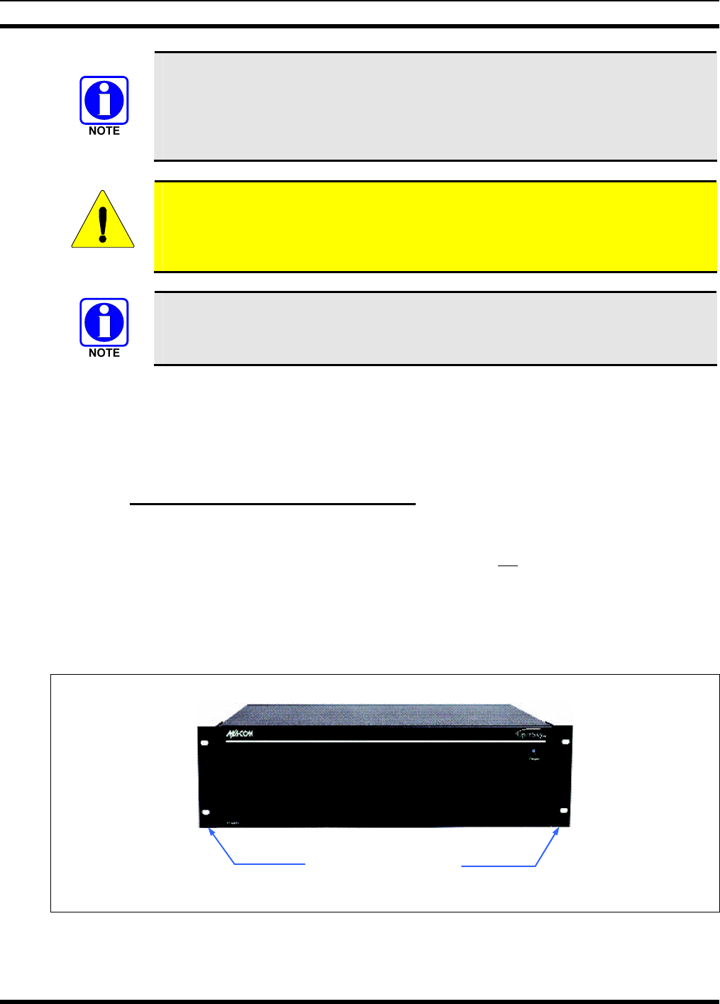
4.3.1 Rack-Mount and Desktop Mounting
The CS-7200 is designed for mounting within a 19-inch rack-mount cabinet. Its height is three rack-units
(5.25 inches). Removable mounting brackets are attached to the side corners near the front panel of the
CS-7200 at the factory. Bracket-to-cabinet rail mounting screws are not included. See Figure 4-1. The
brackets are not shown in Figure 4-2.
However, the CS-7200 can be placed upon a desktop, tabletop, or another flat horizontal surface with an
adequate size and weight rating. The unit’s dimensions are 5.16 x 17 x 14.15 inches
(13.1 x 43.2 x 35.9 cm) and it weighs approximately 34 pounds (15.42 kilograms). Typically, the
mounting brackets are removed for installations of this type.
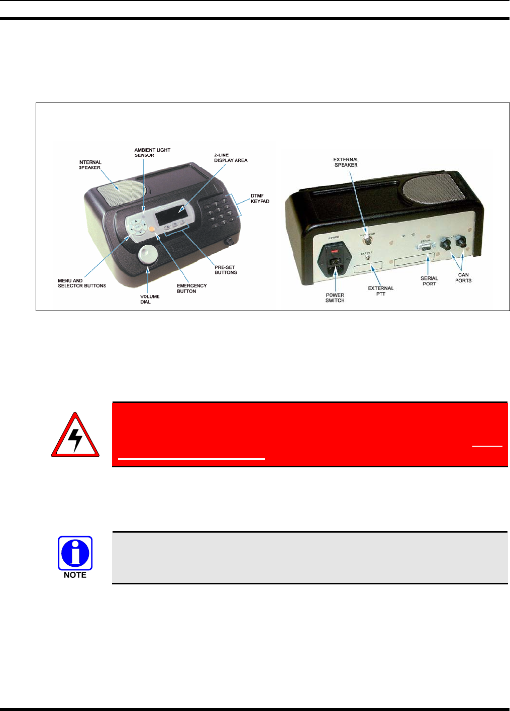
Figure 4-1: CS-7200 Front Panel
19-Inch Rack-Mount
Mounting Brackets
MM-011712-001
14
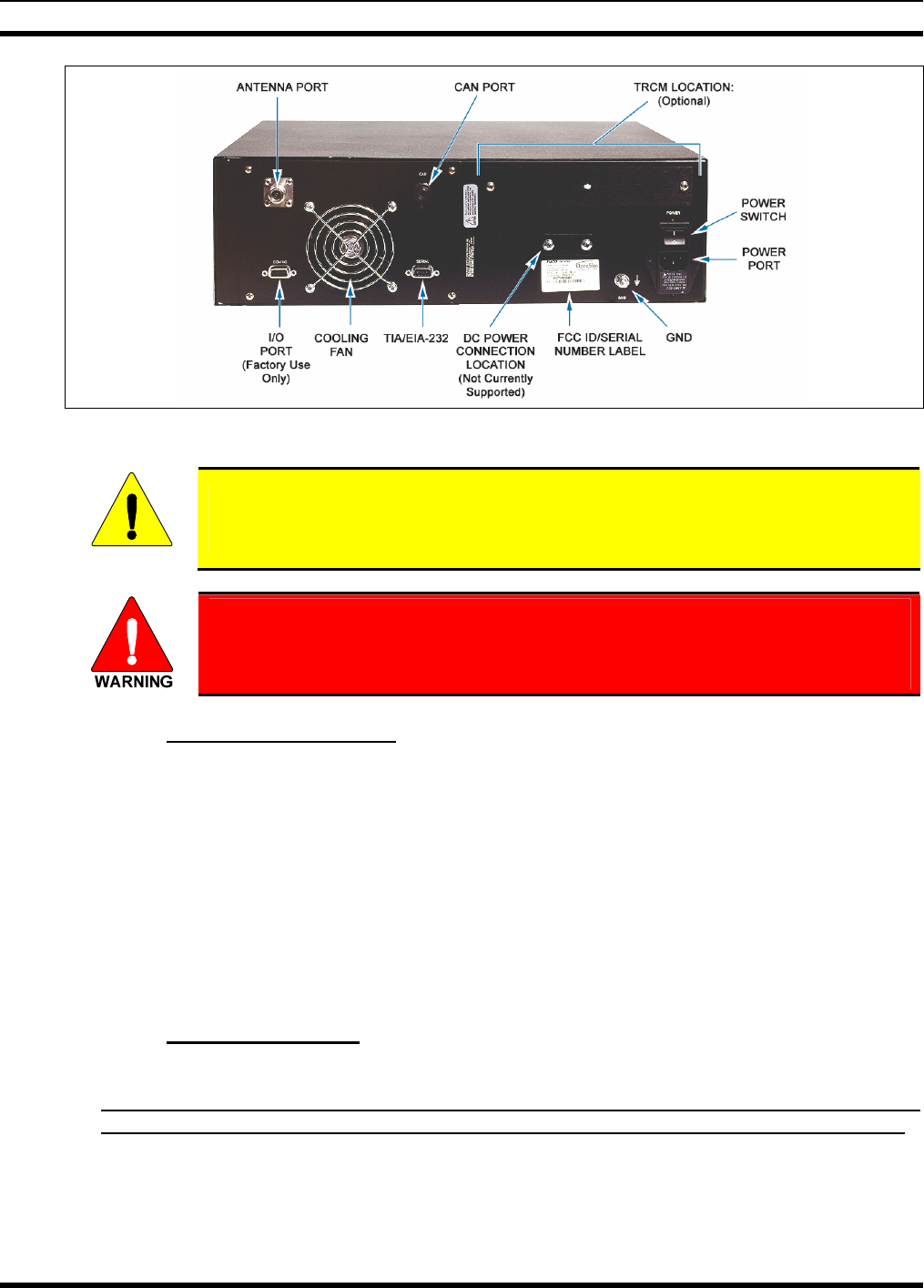
Figure 4-2: CS-7200 Rear Panel
CAUTION
Never place any other equipment directly on top of the CS-7200. The case is not
designed to handle the weight of other equipment.
The CS-7200 must be kept away from sources of heat. Adequate ventilation must
be provided to the air inlet at the rear of the unit where the fan is located and to
the ventilation holes on the side of the unit.
4.3.2 AC Power Connection
The CS-7200 only supports an AC power connection. Follow these general guidelines:
• Ensure familiarity with AC power input connection, including maintenance of the fuse; and,
• Make certain that cable routing will not damage or interfere with any existing wiring at the
installation location.
In order to accommodate both US and European standards, the CS-7200 can be used at voltages in the
range of 110 - 120 Vac (50/60 Hz) and 220 – 240 Vac (50/60 Hz). The power cord for US applications
(110 - 120 Vac) is included with the CS-7200 when it ships from the factory. For European applications,
the appropriate power cord must be purchased separately. The receptacle at the back of the CS-7200 is an
IEC-320 C14-type connector for accepting a cord with an IEC-320 C13-type plug.
4.3.3 Fuse Replacement
In the event that a fuse blows in the CS-7200, follow this replacement procedure:
1. Disconnect AC power from the unit by unplugging the cord from the AC power source or by
unplugging the cord from the IEC-320-type AC power connector on the CS-7200’s rear panel!
2. As shown in Figure 4-3, slip the tip of a small flat-blade screwdriver into the pry slot of the AC
Power Module and pry open the fuse assembly door.
3. Remove the fuse holder and rotate it 180° in order to utilize the spare fuse included. Alternatively,
replace the blown fuse with a new 3-amp, 250-volt fuse.
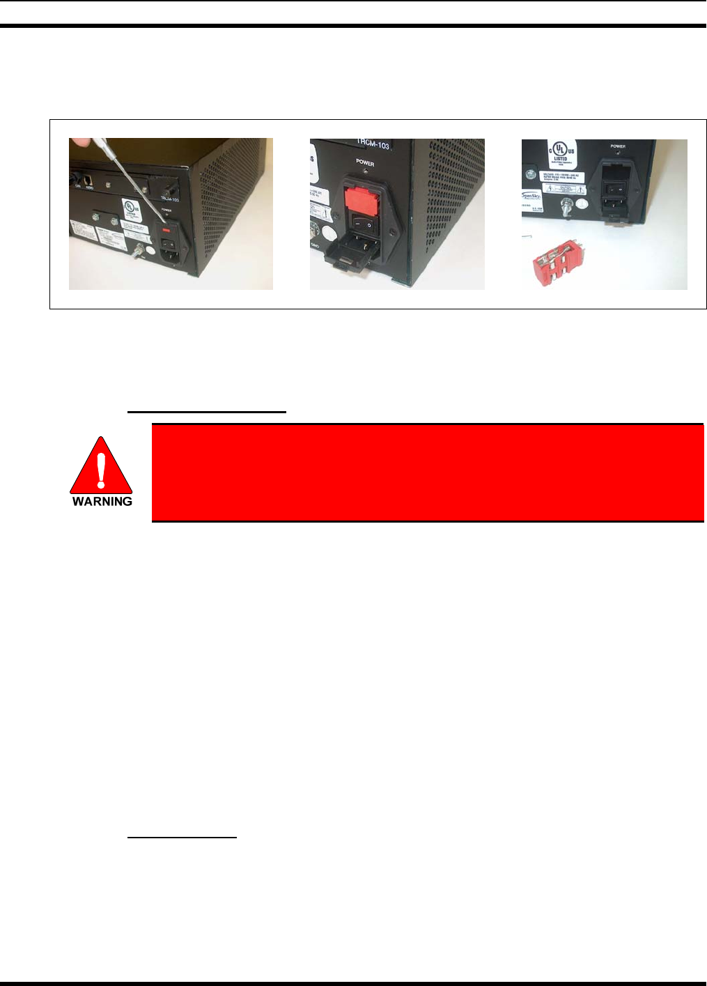
MM-011712-001
15
4. Re-insert and reseat the fuse assembly until the panel snaps back into place.
5. Reconnect AC power to the unit.
Figure 4-3: CS-7200 Fuse Replacement (Rear Panel Views)
4.4 ANTENNA INSTALLATION
4.4.1 General Information
The antenna must be installed by a qualified antenna professional before
completing the CS-7200 installation.
Improper installation of the antenna may lead not only to poor radio
performance, but also to harmful exposure to RF electromagnetic energy.
The CS-7200 is not required to comply with the FCC RF exposure limits for Uncontrolled Exposure
(General Population) and Occupational Exposure because it is assumed that neither uncontrolled nor
occupational exposure is applicable in the general installation configuration. Installation of the antenna
for the CS-7200 is to be performed so that no person is within the distance of maximum permissible
exposure limits specified in the FCC regulations. The CS-7200 must be disabled before maintenance to
the antenna is attempted.
Failure to follow these instructions will void the product warranty and may expose the end user and others
to excessive Radio Frequency hazard. All antennas should be installed outdoors and at distances from
personnel well beyond the minimum allowable distance.
The rooftop-mount Yagi antennas listed in Table 3-1 (on page 11) are recommended. Side-mounting onto
a building with other types of directional antennas is also acceptable as long as proper line-of-sight
alignment can be achieved.
For best performance, the antenna should be placed at least six feet (1.83 meters) from any other antenna
and high enough to clear the line-of-sight of major obstructions.
4.4.2 Coaxial Cable
Many different RF coaxial cable types can be used for the antenna connection as long as the utilized cable
meets the following minimum requirements. Link budget available to cable loss, length of cable, antenna
type used, etc., are issues to consider when selecting the type of cable needed. Minimum cable
requirements are:
• 50-ohm nominal impedance;
MM-011712-001
16
• Required/utilized radio frequency range;
• 1.5:1 VSWR (typical);
• 5 dB/100 feet cable loss (maximum); and,
• Weatherproof construction.
Length of cable should be kept as short as possible to keep cable loss at a minimum. Therefore, the
CS-7200 should be installed within the building in a location as close to the location of the outside
antenna as reasonably possible. Consult with RF equipment installation professionals for more
information.
If routed through walls, plenums, or other channelling aids, the cable must be
protected from excessive handling, bending or rubbing.
1. Install N-type RF connectors onto both ends of the cable. Follow the directions included with the
connectors.
2. At the antenna’s base, screw the cable’s N-type male connector to the N-type female connector at the
base of the antenna. Tighten firmly.
3. Apply the weatherproofing recommended by the antenna manufacturer or supplied with the antenna.
4. At the CS-7200, screw the cable’s N-type male connector to the N-type female antenna port
connector on the rear of the control station. See Figure 4-2 on page 14. Hand-tighten firmly.
To prevent RF leakage and ensure peak performance, verify the RF coaxial
cable’s N-type connector is tight, but not so tight that damage occurs.
4.5 GROUNDING AND LIGHTNING PROTECTION FOR THE CS-7200
Proper grounding is necessary, not only for correct functionality and maximum performance, but also for
minimizing damage that may occur from lightning strikes.
Under the assumption the facility where the CS-7200 is installed is protected properly from lightning
strikes on the AC power line, the CS-7200 is still susceptible to damage from lightning through the RF
antenna port. The CS-7200 does not include an integrated lightning-protection device, so it is
recommended that one be installed. Lightning-protection devices are only effective if the connections are
made as the design intended. Follow the manufacturer’s mounting instructions to ensure a properly
grounded unit.
As shown in Figure 4-2 on page 14, a #10 grounding stud is located at the rear of the CS-7200. For safety
purposes, connect it to the cabinet’s mounting rack with a heavy-gauge wire or braid.
MM-011712-001
17
4.6 SP-103 DESK SET CONNECTION
Figure 4-4 shows front and reviews of the SP-103 Desk Set. An SP-103 is interconnected to the CS-7200
via a CAN cable connection only, which may or may not employ the optional fiber-optic-based CAN Bus
Extender.
FRONT VIEW REAR VIEW
Figure 4-4: SP-103 Front and Rear Panels
The following procedure is recommended to connect the SP-103 to the CS-7200 when using only CAN
cable connections:
1. Place the SP-103 on a desk or tabletop, plug the AC power cord (included with the unit) into the rear
of the unit, and then plug the cord into an AC outlet.
The SP-103 and CS-7200 have the same type of AC power connector
(IEC-320 C14-type). However, the fuse in the SP-103 is different. The
instructions in section 4.3.3 can be used to replace the fuse in the SP-103, except
use a 1-amp fuse in the SP-103.
2. Connect the CAN cable to the CAN port on the rear of the CS-7200. When mating any CAN
connection (cables and terminators), visually align the ¾-moon-shaped keys of the connectors, and
then gently push and turn the outer locking ring of the plug (male) connector clockwise until it stops.
A mild click will be sensed to confirm proper mating.
See section 4.8 for additional CAN cable connection information, including
procedures for in-wall/plenum CAN cable installations, and information about the
CAN Bus Extender.
3. Route the CAN cable to the rear of the SP-103 and connect it to either one of the CAN ports. The
CAN cable carries digitized transmit and receive audio, and control data between the SP-103 and the
CS-7200.
4. Connect a CAN Terminator (part number MACDOS0010) to the other CAN port on the rear of the
SP-103.
5. An optional microphone can be connected to the 14-pin mic connector on the front of the SP-103 as
follows: Align the white arrows on the mating connectors then push the mic cable’s connector into
MM-011712-001
18
the mate—the outer ring of the connector will rotate during the insertion. The outer ring will lock into
place (arrows aligned) when full connection is made and a click will be sensed.
6. An optional external PTT (push-to-talk) footswitch can be used with the SP-103 by plugging it to the
3.5-millimeter jack on the rear panel of the SP-103.
7. The SP-103 has a built-in speaker. If an external speaker is utilized, connect it to the ¼-inch jack on
the rear panel of the SP-103. Connecting an external speaker will disable (silence) the internal
speaker.
CAUTION
Only connect a M/A-COM-approved external speaker to the SP-103. Use of
improperly configured or grounded speaker connection may damage the audio
amplifier circuitry in the SP-103.
8. For data applications, the 9-pin D-subminiature connector on the rear panel of the SP-103 can be
connected to a personal computer’s 9-pin serial communication port. Use TIA/EIA-232 data cable
part number MAMROS0055 (or equivalent). Cable MAMROS0055 is six feet (1.83 meters) long.
4.7 CONNECTING TO A TONE REMOTE CONTROLLER (OPTIONAL)
If the CS-7200 will be connected to and controlled by one or more Tone Remote Controllers (TRCs), the
TRCM-103 Tone Remote Control Module must be installed into the CS-7200, and the CS-7200 and the
TRCM-103 must be properly configured as described in this section. Figure 4-10 shows this installation
and the TRCM-103’s external interfaces.
When not installed in the CS-7200, the TRCM-103 is an exposed printed circuit board
assembly. Therefore, observe precautions for damage due to Electro-Static Discharge
(ESD). Use proper grounding techniques such as a wrist strap connected to a grounded
surface and other approved handling methods in order to minimize the chance of
damage from ESD.
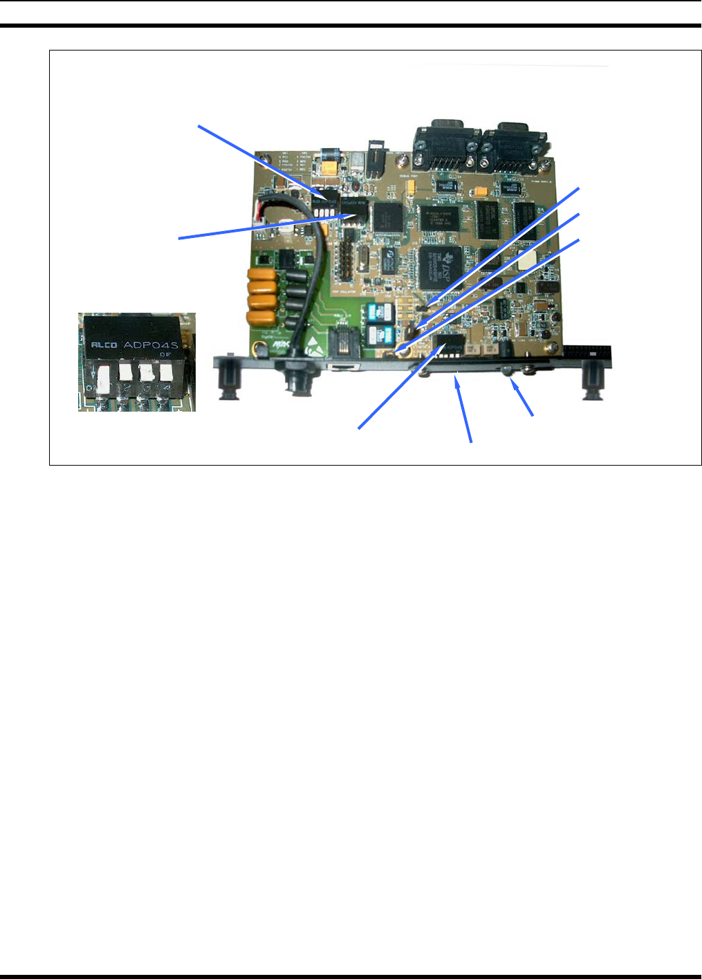
4.7.1 DIP Switch and Jumper Settings
The TRCM-103 is shipped from the factory with default DIP switch and jumper settings. Prior to
installing the TRCM-103 into the CS-7200, verify the switches and jumpers are set appropriately. For
reference in the field, these settings are listed on a label located on the bottom of the TRCM-103. This
label is shown in Figure 4-5.
TRCM-103 DIP switch locations are shown in Figure 4-6 on page 20. Switch positions of SW1 and
SW2 are factory-set and must not be changed. Changes may be required to SW4 position 2 (“SW4-2”)
as presented in the step 3 of this procedure:
1. Referring to Figure 4-6 for switch locations, verify all DIP switch positions are at the factory-default
settings as shown in the “NORMAL OPERATION” part of Figure 4-5. (All positions of SW1 must
be DOWN, SW2 position 1 must be DOWN, SW2 positions 2 through 4 must be UP, and positions 1,
3 and 4 of SW4 must be UP.)
2. The default configuration for jumper J8 on the TRCM-103 is ON (installed). This sets the
TRCM-103’s audio line termination to the low impedance (600-ohm) state so it can be utilized as an
endpoint in the CS-7200-to-TRC(s) 2 or 4-wire audio “chain.” Refer to Figure 4-6 for the location of
jumper J8. If the TRCM-103 is to be configured in the middle of the chain when paralleled TRCs are
employed, see section 4.7.2.3 on page 22 for additional information.
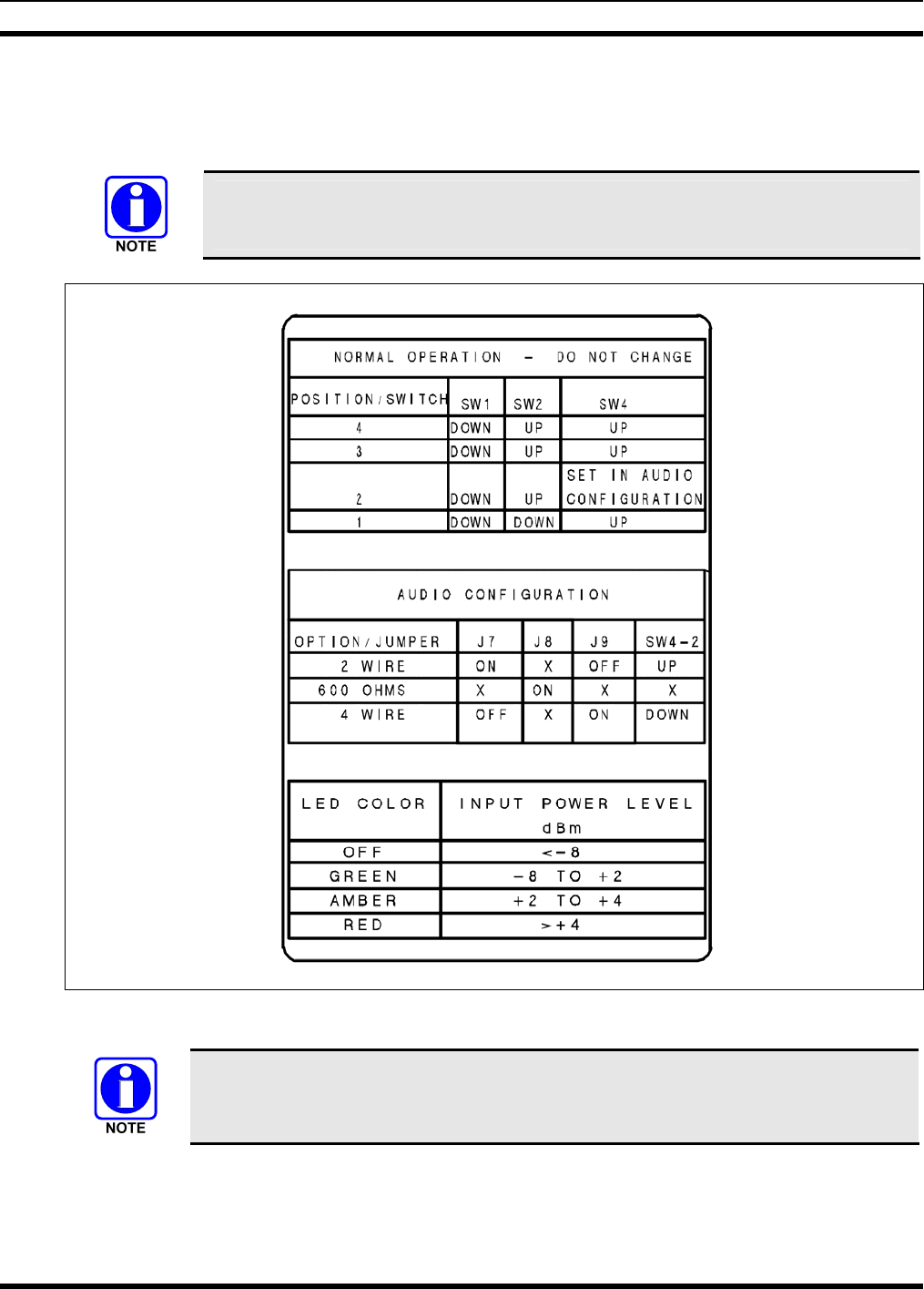
MM-011712-001
19
3. Factory default TRCM-103 settings configure it for a 4-wire line interface to the TRC(s). This is
determined by jumper J9 being ON (installed) and SW4 position 2 being DOWN. If a 2-wire line
interface connects the TRC to the TRCM-103, move the jumper on J9 to J7 and set SW4 position 2
UP. Refer to Figure 4-6 on page 20 as necessary.
A jumper must be on either J9 or J7 and SW4-2 must be in the appropriate setting in
order for the TRCM-103 to work properly.
Figure 4-5: DIP Switch and Jumper Configuration Label (Located on Bottom of TRCM-103)
The TRC operator/dispatcher cannot pre-empt radio-originated calls when 2-Wire
connections are employed between the TRC and the CS-7200. Therefore, 4-wire
connections are recommended when a CS-7200 is interfaced to a TRC.
MM-011712-001
20
Figure 4-6: TRCM-103 Jumper and Switch Settings
Detail of SW2 Settings
(Viewed From Opposite
Side):
1 2 3 4
SW1
SW2
SW4 Tune LED
J7
J8
J9
1 2 3 4
Tunin
g
Panel
MM-011712-001
21
4.7.2 Installation Configurations
The following subsections describe various TRC configurations supported by a TRCM-103 equipped
CS-7200. If more than one TRC is connected to via a TRCM-103, line connections are in parallel and the
TRCM-103 can be configured to operate at either the end or in the middle of the “chain” of paralleled
TRCs. For specific TRC configuration information, refer to the respective TRC’s installation manual
provided by the manufacturer.
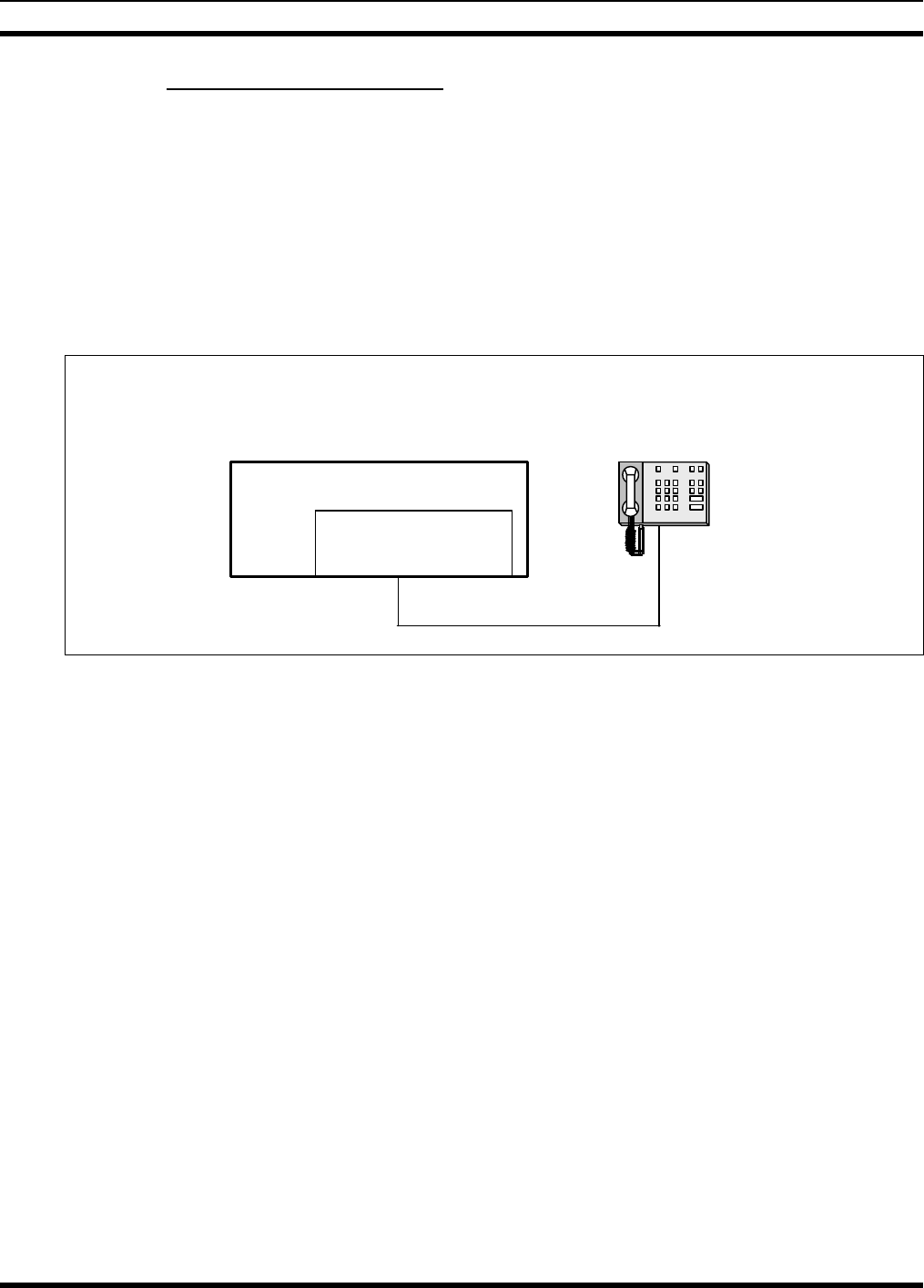
4.7.2.1 TRCM-103 as an Endpoint and Interfaced to a Single TRC
If only one TRC is connected, the TRCM-103 and the TRC are both considered line terminating
endpoints. Both devices must have their line impedance set to the low impedance (600-ohm) state for
proper termination. This line interface configuration is illustrated in the following figure:
Tone Remote
Controller
Line Interface = LOW
impedance
CS-7200 Control Station
TRCM-103
Line Interface = LOW
impedance (600 ohms)
2 or 4-wire line interface
Figure 4-7: TRCM-103 Configured as an Endpoint and Interfaced to One TRC
If using this configuration, no change of jumper J8 is needed from the factory default setting as described
in section 4.7.1 because the factory default setting is low impedance line termination. However, if the line
interface is a 2-wire line connection, the factory default setting of 4-wire line must be changed to 2-wire
line by moving jumper J9 to J7, and setting SW4 position 2 UP as described in section 4.7.1.
MM-011712-001
22
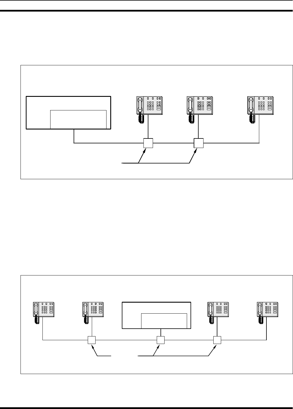
4.7.2.2 TRCM-103 as an Endpoint and Interfaced to Multiple TRCs
The following figure illustrates the TRCM-103 at the end of a “chain” of paralleled TRCs. In this
configuration, the TRCM-103 and the TRC that is furthest away from the TRCM-103 in physical cable
distance must have their line impedance set to the low impedance (600-ohm) state for proper termination.
All other TRCs must be set to the high impedance state.
Tone Remote
Controller 1
Line Interface = HIGH
impedance
CS-7200 Control Station
TRCM-103
Line Interface = LOW
impedance (600 ohms)
2 or 4-wire line interface
Tone Remote
Controller 2
Line Interface = HIGH
impedance
Tone Remote
Controller N
Line Interface = LOW
impedance
Note: Tone Remote
Controller N is furthest
away in physical distance.
Splitters or Terminal Distribution
• • • • • • •
Figure 4-8: TRCM-103 Configured as an Endpoint and Interfaced to Multiple Paralleled TRCs
As with the previous configuration, no change of jumper J8 is needed from the factory default setting as
described in section 4.7.1 because the factory default setting is low impedance line termination. If the line
interface is a 2-wire line connection, the factory default setting of 4-wire line must be changed to 2-wire
line by moving jumper J9 to J7, and setting SW4 position 2 UP as described in section 4.7.1.
4.7.2.3 TRCM-103 in the Middle and Interfaced to Multiple TRCs
The following figure illustrates the TRCM-103 in the middle of a “chain” of TRCs. In this configuration,
the two TRCs furthest away from each other in physical cable distance must have their line impedance set
to the low impedance (600-ohm) state for proper termination. The TRCM-103 and all other paralleled
TRCs must be set to the high impedance state.
CS-7200 Control Station
TRCM-103
Line Interface = HIGH
impedance
2 or 4-wire line interface
Tone Remote
Controller Y
Line Interface = HIGH
impedance
Tone Remote
Controller Z
Line Interface = LOW
impedance
Note: Tone Remote Controller 1
and Z are furthest away in
physical distance. (i.e., “at the
ends of the chain”
)
• • • • • • •
Tone Remote
Controller 1
Line Interface = LOW
impedance
Tone Remote
Controller X
Line Interface = HIGH
impedance
• • • • • • •
Splitters or
Terminal
Distribution
Figure 4-9: TRCM-103 in the Middle of a Chain and Interfaced to Multiple Paralleled TRCs
MM-011712-001
23
To set the TRCM-103 to the high impedance state, remove jumper J8. If the line interface is a 2-wire line
connection, the factory default setting of 4-wire line must be changed to 2-wire line by moving jumper J9
to J7, and setting SW4 position 2 UP as described in section 4.7.1.
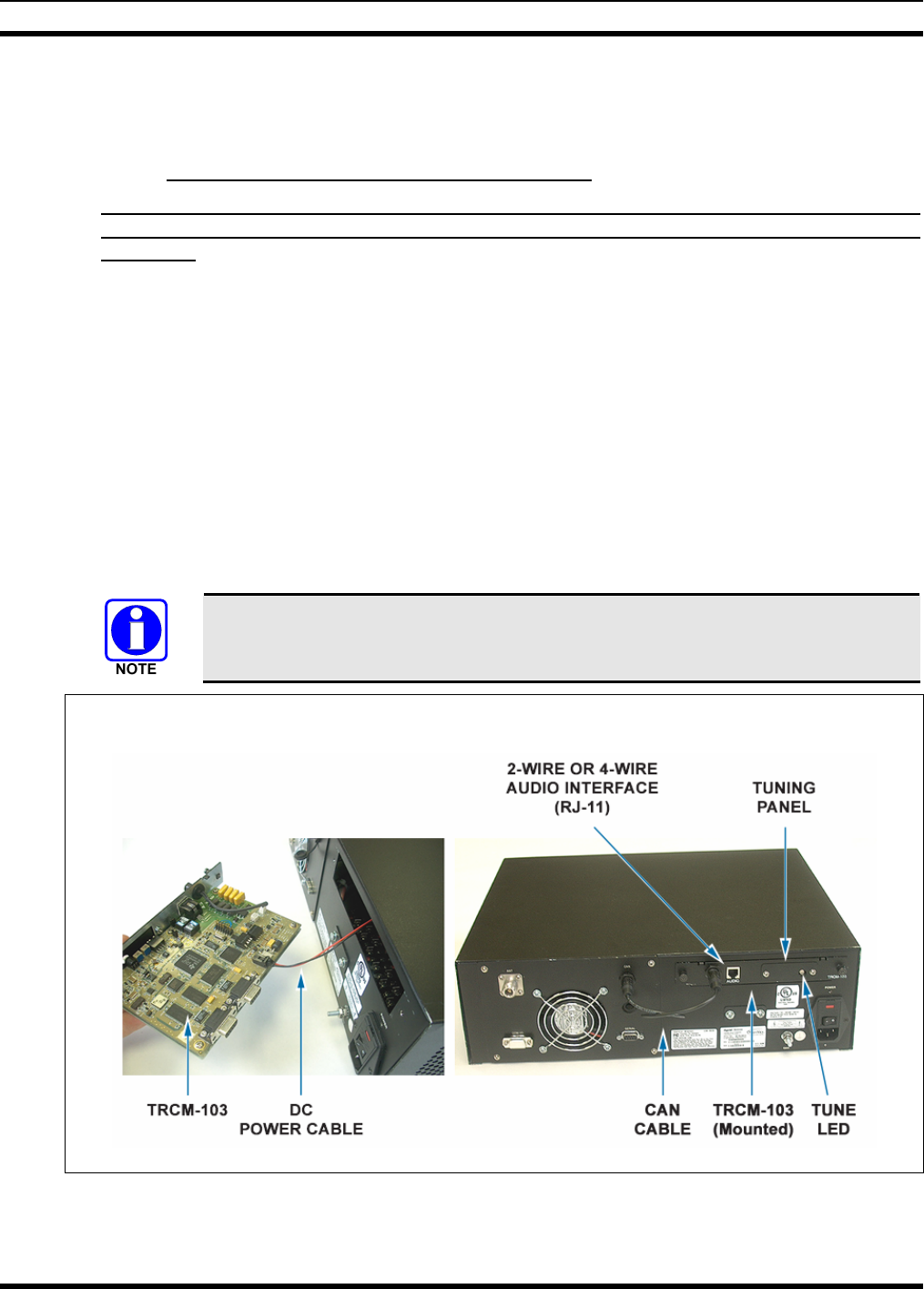
4.7.3 Installing the TRCM-103 into the CS-7200
1. If not already, disconnect AC power from the unit by unplugging the cord from the AC power
source or by unplugging the cord from the IEC-320-type AC power connector on the CS-7200’s
rear panel!
2. At the CS-7200 rear panel, loosen and remove the two (2) Phillips-head screws that secure the blank
panel that covers the slot for the TRCM-103. See Figure 4-2 on page 14.
3. Remove the DC power cable (red and black wire) from the back of the blank panel by untwisting the
twist-lock. The blank panel can be discarded.
4. Connect the DC power cable’s connector to the power connector on the edge of the TRCM-103’s
printed circuit board. See Figure 4-10.
5. With the TRCM-103 facing up (board horizontal and large components up), gently slide it into the
slot and align the captive screws with the screw holes on the CS-7200 chassis.
6. Tighten the TRCM-103 the captive screws firmly, but do not over-tighten.
7. Another connection to the CS-7200 is made with a CAN cable. See Section 4.8.3 for more
information.
The required TRCM-103-to-TRC line-level alignment procedure is presented on page
34 of this manual.
TOP VIEW REAR VIEW
Figure 4-10: TRCM-103 Installation into CS-7200 and its External Interfaces
MM-011712-001
24
4.7.4 Connecting to the TRC
A variety of Tone Remote Controllers (TRCs) can be interfaced to the CS-7200 via the TRCM-103. Two
models supported by M/A-COM are Zetron® Model 280, and GAI-TRONICS® Model ITR2000A. The
information presented in the following subsections describes how hardware connections are made to these
units, although the manufacturer’s instructions included with the unit provide the ultimate guidelines.
Other TRCs typically follow these installation approaches.
In all TRC installation cases, connect TRCM-103 Rx audio lines to TRC Tx audio
lines, and connect TRCM-103 Tx audio lines to TRC Rx audio lines. Line
misconnections will cause link failure and may damage the TRC.
Table 4-1 describes pins of the TRCM-103’s RJ-11 modular jack utilized for 2-wire and 4-wire line
connections. If both 2- and 4-wire connections are available at the TRC, the customer is free to choose
either connection. As the TRCM-103 is factory set for 4-wire operation, 4-wire is recommended, though
not required.
Table 4-1: TRCM-103 Audio Interface Pin-Out
(RJ-11 Modular Jack Labeled “AUDIO”)
RJ-11 PIN SIGNAL
1 (No Connection)
2 4-Wire +RX IN
3 2-Wire +TX OUT/RX IN
4 2-Wire -TX OUT/RX IN
5 4-Wire -RX IN
6 (No Connection)
4.7.4.1 Connecting the Zetron Model 280
The Zetron® Model 280 TRC supports up to four (4) separate control stations and can be configured for
either a 2-wire or a 4-wire audio interface. Installation requires opening the unit to make connections to a
terminal block inside the unit. This terminal block is identified TB1.
For multiple (paralleled) TRCs in which the line impedances must be changed at one or more units, the
Model 280 supports this via configuration jumpers inside the unit. See the Model 280 Installation Manual
for additional information.
A standard one-to-one modular telephone cable can be run directly from the RJ-11 modular jack on the
TRCM-103 to the TRC. However, because the connections at the Model 280 TRC need to be made at
terminal block TB1 inside the unit, either the modular plug at the Model 280 end of the cable needs to be
cut off and the cable’s wires stripped, or a mating jack adapter with “flying” leads must be utilized to
make the connections at the terminal block.
Table 4-2 shows pin-out interconnection details for a 2-wire interface and Table 4-3 shows the same for a
4-wire interface.
MM-011712-001
25
Table 4-2: TRCM-103 to Zetron Model 280 2-Wire Line Interface Connections
TRCM-103 RJ-11 “AUDIO” JACK MODEL 280 TERMINAL BLOCK TB1
Pin Signal Terminal Signal
3 2-Wire +TX OUT/RX IN 8 2W+1
4 2-Wire –TX OUT/RX IN 9 2W–1
Table 4-3: TRCM-103 to Zetron Model 280 4-Wire Line Interface Connections
TRCM-103 RJ-11 “AUDIO” JACK MODEL 280 TERMINAL BLOCK TB1
Pin Signal Terminal Signal
2 4-Wire +RX IN 8 2W+1 (+TX)
3 2-Wire +TX OUT/RX IN 7 4-Wire+1 (+RX)
4 2-Wire –TX OUT/RX IN 10 4-Wire-1 (-RX)
5 4-Wire –RX IN 9 2W–1 (-TX)
4.7.4.2 Connecting the GAI-TRONICS Model ITR2000A
The GAI-TRONICS® Model ITR2000A TRC supports only one control station, but it can be configured
for either a 2-wire or a 4-wire audio interface. Installation does not require the unit to be opened to make
connections, as connections are performed directly at the RJ-11 modular jack labelled “LINE” at the rear
of the unit.
For multiple (paralleled) TRCs, the ITR2000A supports low and high line impedance configuration
changes via its programming configuration. See the ITR2000A’s User and Installation Manual for
additional information.
For a 2-wire line interface connection, a standard one-to-one modular telephone cable can be connected
directly between the TRCM-103’s RJ-11 modular jack and the ITR2000A. The following table lists the
required connections:
Table 4-4: TRCM-103 to GAI-TRONICS Model ITR2000A 2-Wire Line Interface Connections
TRCM-103 RJ-11 “AUDIO” JACK MODEL ITR2000A “LINE” JACK
Pin Signal Pin Signal
3 2-Wire +TX OUT/RX IN 3 2-Wire TX +OUT/RX IN
4 2-Wire –TX OUT/RX IN 4 2-Wire TX -OUT/RX IN
MM-011712-001
26
For 4-wire line interface connections, a crossover (null modem) connection between the TRCM-103 and
the ITR2000A is required to mate the RX to TX and TX to RX connections. A Standard one-to-one
modular cable can be utilized at the ITR2000A’s “LINE” jack, with the crossover made at the
TRCM-103. This will ease wiring when paralleled TRCs are employed, or added at a later date. Up to
ten (10) ITR2000A TRCs can be paralleled together to control a single CS-7200.
Table 4-5: TRCM-103 to GAI-TRONICS Model ITR2000A 4-Wire Line Interface Connections
TRCM-103 RJ-11 “AUDIO” JACK MODEL ITR2000A “LINE” JACK
Pin Signal Pin Signal
2 4-Wire +RX IN 3 2-Wire TX +OUT/RX IN
3 2-Wire +TX OUT/RX IN 2 4-Wire RX +IN
4 2-Wire –TX OUT/RX IN 5 4-Wire RX -IN
5 4-Wire –RX IN 4 2-Wire TX -OUT/RX IN
The required TRCM-103-to-TRC line-level alignment procedure is presented on page
34 of this manual.
4.8 CONNECTING THE CAN CABLE
The CS-7200’s CAN port needs to be connected to provide the user interface for the CS-7200. As shown
in Figure 4-2, the CAN port is located at the rear of the CS-7200. This is where the SP-103 or TRCM-103
CAN cable is connected. To make CAN connections, visually align the 3-pin male connectors of the cable
to the 3-pin female connectors on each unit. Connect by pushing and twisting the outer housing of the
cable connector until a click is sensed. Do not use excessive force when twisting.
The CAN digital interface must be terminated properly at both ends in order to work
correctly. The CS-7200 has an internal terminator that provides the termination for its
end.
Currently, in a multiple CAN device (i.e., SP-103) configuration, all daisy chaining
must be performed such that the CS-7200 is an end point, because the CS-7200 is
internally terminated. Do not use a CAN Y-Cable to split the CAN port of the
CS-7200 to two separate devices.
4.8.1 SP-103 CAN Connections
The SP-103 Desk Set has two CAN ports on its rear panel to support “daisy-chaining” of multiple
SP-103s or other CAN devices. When an SP-103 is in the middle of a chain (e.g., Control Station on one
end and a different SP-103 on the other), two separate CAN cables connect to the two ports. When the
SP-103 is at the end of a chain of devices, one CAN port connects to the previous CAN device and the
other port must be terminated with a CAN Terminator (part number MACDOS0010).
4.8.1.1 Collocated Installations
For installations in which the SP-103 is in the same location as the CS-7200 and no routing of cables into
walls or through plenums is required, the standard CAN cable can be used. For cables whose connectors

MM-011712-001
27
can be routed without the fear of being damaged in routing (e.g., cables do not need to be snaked through
holes), the molded CAN cables are preferred, part number CA-009562-xxx. See Table 3-1 on page 11 for
specific cable part numbers. The “xxx” suffix specifies cable length in feet.
If connectors might get snagged or damaged during routing, CAN cable part number 9451-BLK-1000 is
available by the spool (1000 feet of cable). However, a CA-009562-xxx CAN cable must also be
purchased, as its molded connectors must be splice to both ends of the 9451-BLK-1000 spooled cable.
Splicing instructions are presented on page 28.
4.8.1.2 In-Wall/Plenum CAN Cable Installations for Remote SP-103
4.8.1.2.1 Cable Requirements and Routing
As described in the previous section, various lengths of molded CAN cables are available for the SP-103.
The standard molded CAN cable, part number CA-009562-030, is primarily for general use. However, for
in-building applications, this cable does not meet certain safety agency codes for routing through walls
and plenums. For this reason, a plenum-rated cable, Belden part number 87761-RED-1000, can be
purchased by the spool. This cable is recommended for in-wall/plenum CAN cable installations because
of its properties of impedance, shielding, and flexibility. In-wall/plenum routing faces the rigors of
“snaking” and pulling of the cable. These actions can damage installed connectors. Therefore, a procedure
for routing raw cable through the walls and mating connections reliably is necessary.
Figure 4-11 illustrates the general concept for connecting the CS-7200 to the SP-103 via in-wall/plenum
CAN cabling. Follow these requirements:
• Materials (e.g., junction boxes, cabling, etc) must meet all building codes.
• The in-wall/plenum cable must be a plenum-rated, shielded, twisted-wire pair of 22-AWG. Belden
87761 cable is recommended. If the utilized cable does not meet building codes, it must be dressed or
placed inside a conduit (not provided), or some other installation method must be employed so that it
does meet building codes.
• Total length of the CAN cable must not exceed 250 feet (76.2 meters), including any amount of
cable daisy-chained through multiple CAN devices (e.g., the SP-103).
The standard (non-plenum) CAN cable (e.g., CA-009562-030) is spliced to the plenum cable using
3-position terminal blocks placed inside junction boxes. Plenum-rated cable is needed for in-wall/plenum
routing, but the standard cable, as long as it isn’t routed through a wall or concealed ducting, is acceptable
for connections to the wall. The standard cable is needed because its solder-type molded connectors do
not accommodate customary in-field installation.
MM-011712-001
28
CS-7200
Control
Station CAN
Port
3-Pole Terminal Block
(Wago #261-423/341-000)
In-Wall Junction Box
One Half o
f
MACDOS0006-NR030
(Cut to required length)
SP-103
Desk Set
CAN
Port
3-Pole Terminal Block
(Wago #261-423/341-000)
In-Wall Junction Box
Other Half of
MACDOS0006-NR030
(Cut to required length)
CAN Cable Routing
Throughout Building
Belden 87761 Plenum-
Rated Cable (Maximum
length = 220 feet + the
length cut from the
MACDOS0006-NR030
cable)
Figure 4-11: Connecting CS-7200 to the SP-103 via In-Wall/Plenum CAN Cable Connections
4.8.1.2.2 Installation Materials
The following materials are required:
• 3-Pole 2-Conductor Terminal Blocks, WAGO® part number 261-423/341-000 (2 required)
• Junction boxes (2 required)
• Assorted tools for routing cable through walls/plenums and mounting junction boxes
4.8.1.2.3 Splicing CAN Cable
The following procedure is recommended for splicing plenum-rated cable to the standard CAN cable:
1. Cut the standard CAN cable (part number CA-009562-030) approximately in half.
2. If not already, power-off both the CS-7200 and the SP-103. Both units should remain off until after
the cable installation is complete.
3. Connect each end of the cut CAN cable to the CS-7200 and SP-103 CAN ports.
4. Using the cut ends of the cable, determine acceptable locations for wall junction boxes and mount the
two junction boxes using an approved method.
5. Route the cables into the junction boxes and anchor according to building codes.
6. Cut off any excess cable length, allowing at least one foot (0.3 meters) for splicing and servicing. The
total amount of cable removed from both halves is an amount that can be added to the 220 feet of
plenum cable, if needed. For example, if 10 feet of excess length is cut from the standard 30-foot
CAN cable, the plenum cable is allowed to be as long as 230 feet. In any case, do not exceed 250 feet
(76.2 meters) of total CAN cable length.
7. Measure out an amount of spooled plenum cable needed to reach the two junction box splice points
and route it through the building walls, plenums, etc. using approved methods.
8. Route the cable’s ends into the junction boxes and anchor according to building codes.
9. Cut off any excess cable length, allowing a foot or so of length for splicing.
MM-011712-001
29
10. With a 14-AWG wire stripper, strip off 3/4-inch of the cable’s outer jacket and remove any shield
foil. This dimension is critical, as too much unexposed lead length can have adverse effect on
performance. Ensure no damage was done to the individual wires.
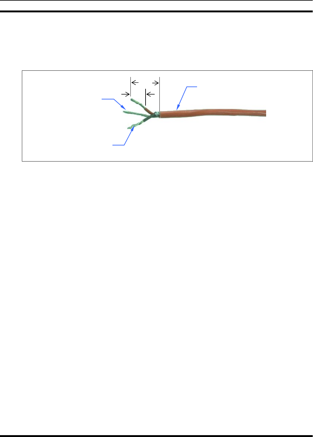
11. With a 22-AWG wire stripper, strip off 5/16-inch of insulation from each individual wire in the
shielded pair. The third wire in the cable is the shield ground wire—do not cut it. See Figure 4-12.
Figure 4-12: Dimensions for Stripping 3-Wire CAN Cables
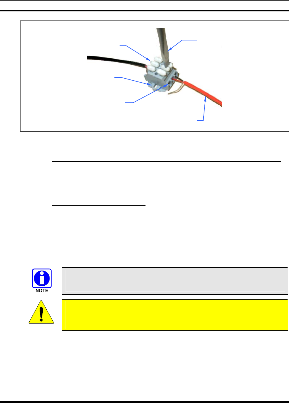
12. At both ends of the spooled plenum cable, simultaneously insert the red and black wires into two
poles of the terminal block by simultaneously pushing two adjacent buttons down with a large #2
flathead screwdriver, and guiding the bare end of the wire into the side openings of the terminal
block. Next, release pressure on the buttons while ensuring the bare wires are visible entering the
block’s clamping mechanisms. See Figure 4-13. The order of wires in the terminal block housing
does not matter, but the red and black wires must be next to each other. Consistency between the two
blocks is recommended.
13. Insert the bare shield wire into the third pole of the terminals block by pushing the button down with
the screwdriver, guiding the wire into the opening, and releasing pressure on the button.
14. Strip and connect the CS-7200 and the SP-103’s standard CAN cable wires to the terminal blocks so
matching wire colors on each half of the standard CAN cable will be electrically connected.
15. Finish the installation by pushing the terminal block into the junction boxes and covering the boxes
appropriately. Alternatively, the terminal blocks may be secured with small screws (not supplied) at
the mounting flanges.
5/16”
3/4”
Stripped Wires
(
1 Pair
)
Shield Wire
Cable’s Outer Jacket
MM-011712-001
30
Figure 4-13: 3-Position Terminal Strip Connections
4.8.2 Connecting via the CAN Bus Extender (Fiber Optic Cable Installations)
When using the CAN Bus Extender to connect an SP-103 to the CS-7200, the extender should be co-
located with and connected directly to the CS-7200. For installation-related information, refer to manual
publication number MM-009088-001.
4.8.3 TRCM-103 CAN Connections
A 0.6-foot CAN cable is included with TRCM-103 when it ships from the factory. Standard TRCM-103
installations require connecting this cable directly between the CS-7200’s CAN port and the TRCM-103’s
CAN port.
If both the SP-103 and the TRCM-103 are connected to a common CS-7200, CAN Y-cable part number
CA-011344, is needed at the TRCM-103’s CAN port to split the CAN connection. In this case, connect
the male connector of the Y-cable to the TRCM-103’s CAN port, one of the female legs to the short
0.6-foot cable from the CS-7200’s CAN port, and the other female leg to the CAN cable from the SP-103.
The CS-7200 can support up to five SP-103s, whether or not a TRCM-103 is installed
in the CS-7200.
CAUTION
The total physical length of CAN cable, including the amount that is “daisy-chained”
between multiple SP-103 Desk Sets, cannot exceed a length of 250 feet (76.2 meters).
Lengths beyond this will cause failure in the communications link between units.
WAGO Terminal
Block Openings
Cable’s Outer Jacket
Push Buttons
Mounting Flange
Screwdriver
MM-011712-001
31
5 POWER-UP PROCEDURE
Unlike many radios, the OpenSky family of radio products power up to the state of last
control. However, the CS-7200 will not be operational unless a CAN device is
connected through the CAN port and this device is itself powered up.
1. Connect AC power to the CS-7200. See section 4.3.2 on page 14 for details.
2. Turn on the CS-7200 via the power switch on its rear panel.
3. Verify power is applied to the CS-7200 by checking for a lit green LED on the front of the CS-7200.
4. If the CAN Bus Extender is employed, connect its “wall cube” power supply to an appropriate AC
power source and then connect the supply’s 24-volt DC cable to the extender’s DC power input jack.
5. If using an SP-103, connect AC power to it and turn it on via the power switch on its rear panel.
Verify the SP-103 display is illuminated and not reporting any errors.
The SP-103 will go through a short boot sequence, then attempt to logon to the
OpenSky network. If the CAN cable is not connected (see section 4.8) to the CS-7200
or if power to the CS-7200 is not applied, the display will indicate an error.
If using a third-party Tone Remote Controller (TRC), follow manufacturer’s
instructions regarding TRC power up.
MM-011712-001
32
6 CHANGING OPERATING MODE
If for some reason the CS-7200 is not set to the proper OpenSky Trunking Protocol (OTP) operating
mode, or if verification that the unit is in OTP mode is sought, this can be accomplished either via an
SP-103 or by a PC running a terminal application such as Microsoft Windows HyperTerminal. Both
methods are described in the following subsections.
6.1 SP-103 METHOD
1. Verify both the CS-7200 and the SP-103 are powered-up and no errors are reported by the SP-103.
2. Using the SP-103 menu selection buttons, press ▲ (up arrow) repeatedly until “MODE” appears in
the display.
3. Press .
4. Press ► (right arrow) repeatedly until “OTP” appears in the display.
5. Press .
6. Press ► again and then again to confirm the selection.
7. The CS-7200 will go through a short reboot sequence during which time the OTP operating mode and
version number will be reported in the display.
6.2 PC RUNNING A TERMINAL APPLICATION METHOD
If a TRCM-103 is installed in a CS-7200 but an SP-103 is not available, a PC running a terminal
application can be used to set OTP operating mode. Settings shown in the Table 6-1 are required and
correspond to the Microsoft Windows HyperTerminal program. Consult with the user’s manual of other
terminal applications as necessary.
1. Ensure the CS-7200 is powered off.
2. Using a standard modem-type TIA/EIA-232 serial cable (MAMROS0055 or equivalent), connect the
CS-7200 to the PC by connecting the PC’s serial (COM) port to the 9-pin D-subminiature (DB-9)
connector on the rear of the CS-7200 labelled “SERIAL”.
3. Run the terminal application.
4. Follow the POWER-UP PROCEDURE presented in Section 5 to power up the CS-7200.
5. The operating mode will be displayed within the PC’s terminal program.
6. If the mode is not OTP (followed by its version), type atz9 (case sensitive) and then press <Enter> at
the PC’s keyboard. The CS-7200 will go through a rebooting sequence and the mode will change to
OTP.
MM-011712-001
33
Table 6-1: HyperTerminal Settings Required for Changing Operating Mode
“General” or “Connect To” Tab:
Connect Using COM 1
Configure (Button)
Bits per Second 19200
Data Bits 8
Parity None
Stop Bits 1
Flow Control None
“Settings” Tab:
Terminal Keys (Selected)
Emulation VT100
Backscroll buffer Line 500
ASCII Setup (Button) (Everything should be unselected
Line Delay and Character set to 0)
Terminal Settings (Button)
Check Off 132 Column Mode
Character Set ASCII

MM-011712-001
34
7 LINE-LEVEL ALIGNMENT FOR A TRCM-103
EQUIPPED STATION
Proper line-level alignment is required when using the TRCM-103 to interface the CS-7200 to a Tone
Remote Controller (TRC). Complete the following two procedures to ensure proper line level alignment:
7.1 TRCM-103 TO TONE REMOTE CONTROLLER
1. If installed, temporarily disconnect the short CAN cable between the TRCM-103’s CAN port and the
CS-7200’s CAN port.
2. If not already, connect either a 2-wire or a 4-wire line interface cable between the RJ-11 jack at the
TRCM-103 (jack labelled “AUDIO”) and the TRC. See Figure 7-1 on page 34, Section 4.7.4 on page
24, and follow all manufacturer’s instructions for connecting to and setting up the TRC.
3. Using a Phillips head screwdriver, remove the two (2) screws securing the TRCM-103 tuning panel to
the rear of the TRCM-103. See Figure 7-1.
4. Temporarily set SW4 position 1 to the DOWN position. This causes the TRCM-103 to output a 1 kHz
tone onto the line interface.
5. Monitor the line interface output level at the TRCM-103 using a true-RMS reading multimeter.
6. Using a small Phillips head screwdriver, adjust the TRCM-103’s Output Trim Pot until a reading of
0 dBm (770 mV rms @ 600-ohm impedance) at 1 kHz is obtained at the TRCM-103’s line interface
output.
7. Follow the alignment procedure defined by the manufacturer of the TRC to align its line interface
input level as required. Repeat at each paralleled TRC connected to the CS-7200.
8. At the TRCM-103, set SW4 position 1 back to the UP position to resume normal operation.
9. Continue with the procedure presented in the next section.
Figure 7-1: TRCM-103 Line-Level Adjustments
TO/FROM TONE
REMOTE
CONTROLLER
MM-011712-001
35
7.2 TONE REMOTE CONTROLLER TO TRCM-103
1. Follow the alignment procedure defined by the manufacturer of the TRC to align its line interface
output level to provide a 0 dBm 1 kHz tone signal at its line output.
2. Adjust the TRCM-103’s Input Trim Pot until the tune LED’s color turns to amber, then turn the pot in
the opposite direction to the point where the LED just changes to green.
3. If paralleled TRCs are employed, repeat steps 1 and 2 until an acceptable balance can be achieved
between the TRC with the most line loss and the TRC with the least line loss. Also refer to the
following NOTE.
4. Re-install the tuning panel so the LED protrudes through the access hole in the panel. Do not over-
tighten the screws.
5. Reconnect the short CAN cable between the TRCM-103’s CAN port and CS-7200’s CAN port.
If paralleled TRCs are employed and a major line level difference exists between two
or more TRCs, good signal level balance can normally be achieved as follows:
1. Initially align the TRCM-103 Input Trim Pot using the TRC with the most line loss
(i.e., the lowest 1 kHz signal at the TRCM-103).
2. At each of the other paralleled TRCs in the system, lower the TRC line interface
output level until the tune LED at the TRCM-103 just turns green. Do not adjust
the TRCM-103’s Input Trim Pot.
While this method will improve overall system performance, too high or too low of
TRC intercom levels may result. If so, improve (decrease) line loss differences
between the TRCs and the CS-7200 and/or perform individual intercom level
adjustment at each TRC in accordance with the TRC manufacturer’s instructions.
MM-011712-001
36
8 PROGRAMMING TONE FUNCTIONS TO MATCH TRC
BUTTONS (OPTIONAL)
The purpose of having a Tone Remote Controller (TRC) is to remotely extend the functions of the
Control Station, as if the user had access to a user interface such as the SP-103. The benefit of having a
TRC is that a single Control Station can be operated from a great distance (limited by telephone line
capabilities), whereas the SP-103 has a cable length limitation of 250 feet maximum. However, the TRC
has the limitation of only allowing up to sixteen (16) functions to be defined/controlled. Nevertheless, in a
dispatch or supervisory environment, this 16-function limitation is generally acceptable.
The 16-function limitation is actually a design limitation for standard TRCs. It corresponds to the
maximum number of function tones (i.e., audio frequencies) that a TRC can send out. Standard function
tone frequencies are 550 to 2050 Hz in 100 Hz steps. Typically, one of these tones is reserved for a
“monitor” function. Most TRCs can be programmed to output a specific frequency when a certain button
or combination of buttons is pressed on the unit.
Table 8-1 lists function tones and the corresponding audio frequencies. The TRCM-103 only supports
tones down to 550 Hz. Some TRCs may allow lower frequencies, but the TRCM-103 will not support
them.
Table 8-1: Function Tone Frequencies
FUNCTION
TONE NO. FREQUENCY
(HZ) FUNCTION
TONE NO. FREQUENCY
(HZ)
1 2050 9 1250
2 1950 10 1150
3 1850 11 1050
4 1750 12 950
5 1650 13 850
6 1550 14 750
7 1450 15 650
8 1350 16 550
The TRCM-103 decodes these function tones and translates them into CAN messages for CS-7200
interpretation. These CAN messages mimic the messages that an SP-103 would produce when certain
buttons are pressed on its front panel.
There are only three types of button presses that can be programmed: Emergency Start, Emergency Stop,
and Presets.
Some SP-103 functions, such as volume control, are locally controlled; therefore,
these functions do not need to be mimicked by the TRCM-103. Other functions, such
as menu navigation and display control, only apply to the SP-103 user interface and
therefore also do not need to be mimicked.
MM-011712-001
37
To program the CS-7200 to match corresponding function tones from a TRC, both a Personal Computer
(PC) and an SP-103 Desk Set (or CH-103 Control Head) are required. The PC is used to store the
functions of the button presses with the use of a terminal application (e.g., Microsoft Windows
HyperTerminal), and the SP-103 is needed to put the CS-7200 into a specific profile.
In order to program tone remote functions into the CS-7200, a certified M/A-COM
installation technician will be equipped with an SP-103 Desk Set (or a CH-103
Control Head), as well as with a PC. Customers who purchase the TRCM-103 but do
not purchase an SP-103 will not be able to program tone remote functions on their
own.
See Table 6-1 on page 33 for terminal program configuration settings.
8.1 EMERGENCY START
The Emergency Start function mimics the assertion of an emergency call, typically achieved through the
timed pressing of the emergency button on the front panel of the SP-103. Follow this procedure to
program the Emergency Start function:
1. Using a standard modem-type TIA/EIA-232 serial cable (MAMROS0055 or equivalent), connect the
CS-7200 to the PC by connecting the PC’s COM port to the 9-pin D-subminiature (DB-9) connector
on the rear of the CS-7200 labelled “SERIAL”. See Figure 4-2 for CS-7200 connector location.
2. At the PC, start the terminal application (e.g., HyperTerminal) and verify its configuration as listed in
Table 6-1 on page 33.
3. At the PC’s keyboard, type the following command and then press <Enter>:
atsetbutton x,1 where x represents the function tone number (1 to 16 per Table 8-1)
4. Emergency Stop must also be programmed in accordance with the following section.
8.2 EMERGENCY STOP
The Emergency Stop function mimics the ending of an emergency call, typically achieved by pressing of
the emergency button on the front panel of the SP-103 (after an emergency call is started). This function
must be defined in order to cancel an emergency that may have been started erroneously, and to end a
valid emergency call so that system resources can be reclaimed. Follow this procedure to program the
Emergency Start function:
1. If not already, perform the Emergency Start programming procedure presented in the previous
section.
2. At the PC keyboard, type the following command and then press <Enter>:
atsetbutton y,2 where y represents the function tone number (1 to 16 per Table
8-1); y cannot equal x as presented in section 8.1
3. If not programming the Preset function in accordance with the following section, proceed to section
8.4 on page 38 to save the new programming.

MM-011712-001
38
8.3 PRESET
The Preset function mimics the pressing of the Preset button on the front panel of the SP-103. A Preset
brings up a user-defined profile that has been previously programmed into the radio. Presets aid the user
tremendously if multiple users or scenarios need to be controlled or monitored.
A Preset brings up the environment of the user profile. For this reason, the channels
and personality must be loaded into the CS-7200 before performing this procedure.
Program the Preset function in accordance with this procedure:
1. If not already, connect the CS-7200 to the PC by connecting the PC’s COM port to the 9-pin
D-subminiature (DB-9) connector on the rear of the CS-7200 labelled “SERIAL” using a standard
modem-type TIA/EIA-232 serial cable (MAMROS0055 or equivalent). See Figure 4-2 for CS-7200
connector location.
2. At the PC, start the terminal application (e.g., HyperTerminal) and verify its configuration as listed in
Table 6-1 on page 33.
3. Temporarily disconnect the short CAN Cable at the CAN port of the TRCM-103 and connect a CAN
Y-Cable (part number CA-011344) to the TRCM-103’s CAN port.
4. Connect the short CAN Cable to one of the CAN Y-Cable’s “legs” and a second CAN Cable
(e.g., part number CA-009562-030) to the other.
5. Connect this CAN Cable to one CAN port of an SP-103 and a CAN terminator (part number
MACDOS0010) to the other.
6. Power-up the SP-103. If necessary, see section 4.6 for more information.
7. At the PC’s keyboard, type the following command and then press <Enter>:
atsetbutton z,0 where z represents the function tone number (1 to 16 per Table
8-1); this maps the corresponding TRC button as a Preset button;
z must not be equal to x or y as presented in sections 8.1 and 8.2.
8. Using the SP-103, manually scroll through the menus using the navigation pad to bring up the full
user profile that the Preset button will command. This will be the state that the CS-7200 will be
commanded to when the associated TRC button is pressed.
9. Type the following command at the PC and then press <Enter>:
atpreset z where z represents the same function tone number as in step 7;
this stores the current state of the CS-7200 when the Preset is
pressed
10. Repeat steps 7 through 9 for as many Presets as there are unused function tones.
11. Proceed to the next section to save the configuration.
8.4 SAVING NEW PROGRAMMING
To store the above functions permanently, the new programming must be saved:
1. At the PC’s keyboard, type the following command and then press <Enter>:
at&w3
2. Shut down the terminal application running on the PC, disconnect the serial cable from the CS-7200
and reconnect the short CAN Cable to the TRCM-103.
MM-011712-001
39
9 ANTENNA PERFORMANCE TESTS
This section includes test procedures to verify the performance of the control station’s antenna system
installation. Tests require a peak-power reading wattmeter to measure RF power. When testing the
CS-7200 with an antenna, transmissions into free space will occur. To prevent clutter and misuse on an
open talk group, transmit only on a talk group pre-defined for test use.
There are two (2) test procedures included in this section:
• Transmitting into a Dummy Load (into a 50-Ohm RF Terminator)
• Transmitting into the Antenna
Prior to installation, the radio’s power level should be configured as required. The wide
range of power levels indicated in the following procedures takes into account such
things as: customer’s requirements; measurement errors, especially to include
uncalibrated equipment; cabling losses; and voltage and temperature variations. By no
means should the result from Radio Performance Testing in this section be construed
as the exact value of power level output from the radio, as the value is set and more
accurately measured in the factory. The values obtained in these test procedures
determine a successful installation only.
The normal operating mode of the CS-7200 for voice or data communications is the OpenSky Trunking
Protocol (OTP) mode. The radio must be operating in OTP mode during the performance test procedures
presented in this section. To change/verify the current operating mode, see Section 6 (page 32).
MM-011712-001
40
9.1 REQUIRED TEST EQUIPMENT
Table 9-1: Required Test Equipment
TEST EQUIPMENT MODEL / PART NUMBER & DESCRIPTION
Peak Power
Wattmeter
• Bird Electronic Corp. Model 4314B (or equivalent) with N-type female
connectors at input and output ports.
Wattmeter
Slug
• Bird Electronic Corp. Element 25E, 25 watts, 400 - 1000 MHz (or
equivalent).
RF Coaxial
Jumper Cable
• Pasternack Enterprises PE3441LF-36 (or equivalent) 50-Ohm Coaxial
Cable with N-type male connectors, approximately three (3) feet in
length.
The utilized cable must have VSWR below 1.5:1 within the RF passband.
50-Ohm RF
Terminator
(“Dummy Load”)
• Pasternack Enterprises PE6106 (or equivalent) 50-ohm RF terminator
rated at greater than 50 watts power, with N-type male connector.
Antenna
Antenna Performance Tests are completed with the CS-7200 installation’s
700/800 MHz antenna system, per the installation described in Section 4.4 of
this manual.
9.2 TRANSMITTING INTO A DUMMY LOAD
1. Using the N-type male RF coaxial jumper cable, connect the CS-7200’s antenna connector on the rear
of the unit to the wattmeter’s input connector.
2. Connect the 50-ohm dummy load to the wattmeter’s output connector, in place of the antenna cable
from the 700/800 MHz antenna.
A peak-power reading RF wattmeter equivalent to the wattmeter specified in Table
9-1 must be used. Do not use an average or RMS-responding wattmeter.
3. If not already, turn on the CS-7200 and set it to the OTP mode. Refer to Section 6 (page 32) as
necessary.
4. Set the CS-7200 to a test talk group, if available.
It is recommended that a test talk group be allocated for this testing. This same group
should be used during the antenna test procedure which is presented in the subsequent
section.
5. Position the wattmeter’s slug to measure forward RF output power. Rotate it if necessary. The arrow
on the face of the slug must point away from the CS-7200 and towards the dummy load for forward
power measurements.
6. Set the wattmeter to measure peak RF power.
7. Key the CS-7200’s transmitter via a PTT button/switch at the SP-103 or TRC.
MM-011712-001
41
8. Compare the wattmeter’s reading with the target RF output power range of 11.8 – 20.0 watts.
9. If the wattmeter reading is within the range, record the measured value in the appropriate space on
the data collection form near the end of this manual.
If the wattmeter reading is outside the range, check/verify the power supply connections and
voltages, recheck all RF connections, and measure the RF output power again. If problems persist,
contact M/A-COM’s Technical Assistance Center for assistance. TAC contact information is listed on
page 9.
9.3 TRANSMITTING INTO THE ANTENNA
1. Connect the antenna cable from the 700/800 MHz antenna to the wattmeter’s output connector.
2. If not already, turn on the CS-7200 and set it to OTP mode. Refer to Section 6 (page 32) as necessary.
3. Set the CS-7200 to a test talk group, if available.
It is recommended that a test talk group be allocated for this testing. Otherwise,
interference with other radio users in the system may occur.
A peak-power reading RF wattmeter equivalent to the wattmeter specified in Table
9-1 must be used. Do not use an average or RMS-responding wattmeter.
4. Position the wattmeter’s slug to measure forward RF output power. Rotate it if necessary. The arrow
on the face of the slug must point away from the CS-7200 and towards the antenna for forward power
measurements.
5. Set the wattmeter to measure peak RF power.
6. Key the CS-7200’s transmitter via a PTT button/switch at the SP-103 or TRC.
7. Compare the wattmeter reading with the target RF output power range of 11.8 – 20.0 watts.
Transmit only for as long as needed to take the measurement, then immediately
disable the transmission.
8. If the wattmeter reading is within the range, record the value in the appropriate space on the data
collection form near the end of this manual.
If the wattmeter reading is outside the range, check/verify the power supply connections and
voltages, recheck all RF connections, and measure the RF output power again. If problems persist,
contact M/A-COM’s Technical Assistance Center for assistance. TAC contact information is listed on
page 9.
9. Position the wattmeter’s slug to measure reverse (reflected) RF power from the antenna. The arrow
on the face of the slug must point away from the antenna and to the CS-7200 to measure reverse
power.
10. Verify the wattmeter is still set to measure peak RF power.
11. Key the CS-7200’s transmitter via a PTT button/switch at the SP-103 or TRC.
12. Compare the wattmeter reading with the RF power output range of 2 watts or less.
MM-011712-001
42
Transmit only for as long as needed to take the measurement, then immediately disable
the transmission.
13. If the wattmeter reading is within the range, record the value in the appropriate space on the data
collection form near the end of this manual.
If the wattmeter reading is outside the range, make sure the antenna is consistent with the specified
frequency range of the CS-7200. For example, if the CS-7200 is configured for operations in a
700 MHz system, it must be connected to a 700 MHz-capable antenna. Recheck all antenna
connections, and measure the reverse power again. If this fails to produce a reading within the range,
replace the antenna and repeat the entire antenna test procedure. Any value exceeding the maximum
allowable reflected power value will result in a diminished RF output signal. If problems persist,
contact M/A-COM’s Technical Assistance Center for assistance. TAC contact information is listed on
page 9.
14. Disconnect the coaxial cable jumper and wattmeter.
15. Permanently connect the cable from the antenna to the CS-7200’s antenna cable by mating the two
N-type connectors together. Use two pairs of slip-jaw pliers to gently tighten this connection. Do not
over tighten and do not twist the cable.
To prevent RF leakage and ensure peak performance, make sure the RF connectors are
tight, but do not over tighten so connector damage will not occur.
Improper antenna and/or antenna cable installation may lead not only to poor
CS-7200 performance but also to harmful exposure to RF electromagnetic energy.
Testing is complete. The CS-7200 is now ready for normal communications.
MM-011712-001
43
9.4 TEST PERFORMANCE DATA FORM
Enter the information requested on this data collection form. Clip this form and file it as a permanent record of
the tested performance of the CS-7200 radio installation.
Clip
Here
Company Performing Installation Technician Performing Test
Date of Test
(mm/dd/yyyy)
CS-7200 Serial Number Antenna Make and Model Numbers
Power Into a Dummy
Load
Watts
Forward Power With
Antenna Reflected Power
With Antenna
Watts
Watts

MM-011712-001
44
10 COMPLETE THE INSTALLATION
Review and follow guidelines presented in this list before considering the installation complete:
• Verify all electrical connections are connected properly and the associated connector attachment
hardware is tight. Pay special attention to all RF antenna cables and AC power cords!
• Verify all fuses are correctly installed and properly rated.
• Verify all electrical cables and wiring are tied, stowed, and protected so they are out of the way of
casual contact, away from sources of extreme heat, and wire chafing cannot occur. Pay special
attention to all RF antenna cables and AC power cords!
• Verify all related mechanical hardware is mounted securely and all respective mounting hardware is
tight.
• Remove all tools and unused hardware from installation area(s).
• Verify the test performance data has been recorded on the data collection form shown in this manual.

MM-011712-001
45
11 WARRANTY
A. M/A-COM, Inc. (hereinafter "Seller") warrants to the original purchaser for use (hereinafter "Buyer") that
Equipment manufactured by or for the Seller shall be free from defects in material and workmanship, and
shall conform to its published specifications. With respect to all non-M/A-COM Equipment, Seller gives no
warranty, and only the warranty, if any, given by the manufacturer shall apply. Rechargeable batteries
are excluded from this warranty but are warranted under a separate Rechargeable Battery Warranty
(ECR-7048).
B. Seller’s obligations set forth in Paragraph C below shall apply only to failures to meet the above
warranties occurring within the following periods of time from date of sale to the Buyer and are
conditioned on Buyer’s giving written notice to Seller within thirty (30) days of such occurrence:
1. for fuses and non-rechargeable batteries, operable on arrival only.
2. for parts and accessories (except as noted in B.1) sold by Seller’s Service Parts Operation, ninety (90)
days.
3. for PANTHER™ Series hand-portable and mobile radios, two (2) years.
4. for all other equipment of Seller’s manufacture, one (1) year.
C. If any Equipment fails to meet the foregoing warranties, Seller shall correct the failure at its option (i) by
repairing any defective or damaged part or parts thereof, (ii) by making available at Seller’s factory any
necessary repaired or replacement parts, or (iii) by replacing the failed Equipment with equivalent new or
refurbished Equipment. Any repaired or replacement part furnished hereunder shall be warranted for the
remainder of the warranty period of the Equipment in which it is installed. Where such failure cannot be
corrected by Seller’s reasonable efforts, the parties will negotiate an equitable adjustment in price. Labor
to perform warranty service will be provided at no charge during the warranty period only for the
Equipment covered under Paragraph B.3 and B.4. To be eligible for no-charge labor, service must be
performed at a M/A-COM factory, by an Authorized Service Center (ASC) or other Servicer approved for
these purposes either at its place of business during normal business hours, for mobile or personal
equipment, or at the Buyer’s location, for fixed location equipment. Service on fixed location equipment
more than thirty (30) miles from the Service Center or other approved Servicer’s place of business will
include a charge for transportation.
D. Seller’s obligations under Paragraph C shall not apply to any Equipment, or part thereof, which (i) has
been modified or otherwise altered other than pursuant to Seller’s written instructions or written approval
or, (ii) is normally consumed in operation or, (iii) has a normal life inherently shorter than the warranty
periods specified in Paragraph B, or (iv) is not properly stored, installed, used, maintained or repaired, or,
(v) has been subjected to any other kind of misuse or detrimental exposure, or has been involved in an
accident.
E. The preceding paragraphs set forth the exclusive remedies for claims based upon defects in or
nonconformity of the Equipment, whether the claim is in contract, warranty, tort (including negligence),
strict liability or otherwise, and however instituted. Upon the expiration of the warranty period, all such
liability shall terminate. The foregoing warranties are exclusive and in lieu of all other warranties, whether
oral, written, expressed, implied or statutory. NO IMPLIED OR STATUTORY WARRANTIES OF
MERCHANTABILITY OR FITNESS FOR PARTICULAR PURPOSE SHALL APPLY. IN NO EVENT
SHALL THE SELLER BE LIABLE FOR ANY INCIDENTAL, CONSEQUENTIAL, SPECIAL, INDIRECT OR
EXEMPLARY DAMAGES.
This warranty applies only within the United States.
M/A-COM, Inc. M/A-COM, Inc.
1011 Pawtucket Blvd. 221 Jefferson Ridge Parkway
Lowell, MA 01853 Lynchburg, VA 24501
1-877-OPENSKY 1-800-528-7711
ECR-7047C

M/A-COM Wireless Systems
221 Jefferson Ridge Parkway
Lynchburg, Virginia 24501
(Outside USA, 1-434-385-2400) Toll Free 1-800-528-7711
www.macom-wireless.com Printed in U.S.A