HARRIS M7200 M7200 700/800 MHz Mobile Radio User Manual manual 1
Harris Corporation M7200 700/800 MHz Mobile Radio manual 1
HARRIS >
Contents
manual 1

Operator’s Manual
MM23016
Sep-05
M7200 Series
Digital Mobile Radio

MANUAL REVISION HISTORY
REVISION DATE REASON FOR CHANGE
- Sep. 2005 Initial Release.
M/A-COM Technical Publications would particularly appreciate feedback on
any errors found in this document and suggestions on how the document could
be improved. Submit your comments and suggestions to:
Wireless Systems Business Unit or fax your comments to: (434) 455-6851
M/A-COM, Inc.
Technical Publications or e-mail us at: techpubs@tycoelectronics.com
221 Jefferson Ridge Parkway
Lynchburg, VA 24501
CREDITS
This device is made under license under one or more of the following US patents: 4,590,473;
4,636,791; 5,148,482; 5,185,796; 5,271,017; 5,377,229; 4,716,407; 4,972,460; 5,502,767;
5,146,497; 5,164,986; 5,185,795.
The voice coding technology embodied in this product is protected by intellectual property rights
including patent rights, copyrights, and trade secrets of Digital Voice Systems, Inc. The user of
this technology is explicitly prohibited from attempting to decompile, reverse engineer, or
disassemble the Object Code, or in any other way convert the Object Code into human-readable
form.
OpenSky is a registered trademark of M/A-COM, Inc.
All other brand and product names are trademarks, registered trademarks or service marks of their
respective holders.
NOTICE!
This manual covers M/A-COM products manufactured and sold by M/A-COM, Inc.
Repairs to this equipment should be made only by an authorized service technician or facility
designated by the supplier. Any repairs, alterations or substitutions of recommended parts made
by the user to this equipment not approved by the manufacturer could void the user's authority to
operate the equipment in addition to the manufacturer's warranty.
This manual is published by M/A-COM, Inc., without any warranty. Improvements and changes
to this manual necessitated by typographical errors, inaccuracies of current information, or
improvements to programs and/or equipment, may be made by M/A-COM, Inc., at any time and
without notice. Such changes will be incorporated into new editions of this manual. No part of
this manual may be reproduced or transmitted in any form or by any means, electronic or
mechanical, including photocopying and recording, for any purpose, without the express written
permission of M/A-COM, Inc.
Copyright© 2005, M/A-COM, Inc. All rights reserved.
2

3
TABLE OF CONTENTS Page
1 SAFETY SYMBOL CONVENTION.......................................................6
2 RF ENERGY EXPOSURE INFORMATION ........................................7
2.1 RF ENERGY EXPOSURE AWARENESS, CONTROL
INFORMATION, AND OPERATION INSTRUCTIONS FOR
FCC OCCUPATIONAL USE REQUIREMENTS .............................7
2.1.1 Federal Communications Commission Regulations...........8
2.2 COMPLIANCE WITH RF EXPOSURE STANDARDS....................8
2.2.1 Mobile Antennas................................................................9
2.2.2 Approved Accessories .....................................................10
2.2.3 Contact Information.........................................................10
3 OPERATION SAFETY RECOMMENDATIONS...............................11
3.1 TRANSMITTER HAZARDS ...........................................................11
3.2 SAFE DRIVING RECOMMENDATIONS......................................11
4 OPERATING RULES AND REGULATIONS.....................................13
4.1 OPERATING TIPS...........................................................................14
5 PRODUCT DESCRIPTION ..................................................................15
5.1 VOICE OPERATION.......................................................................16
5.2 DATA OPERATION ........................................................................16
5.3 REMOTE CONTROL HEAD OPERATION ...................................16
5.4 INTERCOM OPERATION...............................................................17
5.5 PERSONALITY................................................................................17
5.5.1 Profiles.............................................................................17
5.5.2 Talk Groups .....................................................................18
5.6 GPS OPTION....................................................................................18
5.7 FRONT PANEL................................................................................19
5.8 TRANSCEIVER REAR PANEL......................................................20
5.9 CONTROL HEAD REAR PANEL...................................................21
6 OPERATION ..........................................................................................22
6.1 CH-103 FRONT PANEL COMPONENTS ......................................22
6.2 DISPLAY OVERVIEW....................................................................24
6.2.1 Network Connectivity Icon..............................................24
6.2.2 Volume Level Icon ..........................................................24
6.2.3 Display’s Top Line ..........................................................25
6.2.4 Display’s Bottom Line.....................................................25
6.2.5 Dwell Display ..................................................................25
6.2.6 Menu Display and Control Area ......................................28
6.2.7 Dwell Display User-Selectable ........................................28
6.3 BASIC RADIO OPERATION..........................................................29
6.3.1 Turning the Radio On ......................................................29
6.3.2 Self-Test...........................................................................32
6.3.3 “Logging In” to the Network ...........................................32
6.3.4 Logging off the Network..................................................33
6.3.5 Turning the Radio Off......................................................33
6.3.6 Receiving and Transmitting Voice Calls..........................33
6.3.7 Radio Tones.....................................................................34
6.3.8 Adjusting Side Tone Audio Level....................................36
6.3.9 Adjusting Display & Button Backlight Brightness ..........37
6.3.10 Adjusting Speaker/Headset Audio Treble Level..............37
6.3.11 Stealth Mode....................................................................38

4
TABLE OF CONTENTS Page
6.3.12 Checking or Changing the Active Profile........................38
6.3.13 Checking or Changing the Selected Talk Group..............39
6.4 INTERCOM MODE ......................................................................... 40
6.5 TALK GROUP LOCK OUT.............................................................41
6.5.1 Locking Out a Talk Group............................................... 41
6.5.2 Unlocking a Talk Group .................................................. 42
6.5.3 Caution Regarding Profile Changes................................. 42
6.6 SCAN MODE ...................................................................................43
6.6.1 Checking or Changing Active Scan Mode....................... 43
6.6.2 Changing Priority Talk Group.........................................44
6.7 SELECTIVE CALL..........................................................................44
6.7.1 Making a Selective Call...................................................44
6.7.2 Receiving a Selective Call ............................................... 45
6.7.3 Selective Alert .................................................................45
6.8 TELEPHONE INTERCONNECT CALLS.......................................48
6.9 EMERGENCY COMMUNICATIONS............................................48
6.9.1 Declaring an Emergency Call or Alert.............................49
6.9.2 Clearing an Emergency Call or Alert...............................50
6.9.3 Receiving an Emergency Call..........................................50
6.9.4 Dismissing an Emergency Call........................................51
6.10 DUAL-TONE MULTI-FREQUENCY KEYPAD............................51
6.10.1 Password Entry................................................................53
6.11 ENCRYPTION .................................................................................54
6.11.1 Automatic Encryption......................................................54
6.11.2 Manual Encryption ..........................................................54
6.12 PRESET BUTTONS......................................................................... 56
6.13 DYNAMIC REGROUPING.............................................................56
6.14 GPS COORDINATES ......................................................................56
6.15 ENGINEERING DISPLAY..............................................................57
6.15.1 Voice and Data Registration Codes .................................57
6.15.2 Transceiver Status............................................................57
6.15.3 Receive Signal Strength Indication (RSSI)...................... 59
6.15.4 Control Block Symbol Error Rate (CBSER)....................59
7 BASIC TROUBLESHOOTING ............................................................ 60
8 WARRANTY .......................................................................................... 62

5
TABLE OF CONTENTS Page
FIGURES
Figure 5-1: Personality Structure Example........................................................18
Figure 5-2: CH-103/103PA Front Panel............................................................19
Figure 5-3: Transceiver Rear Panel ...................................................................20
Figure 5-4: CH-103 Control Head Rear Panel...................................................21
Figure 6-1: CH-103 Front Panel Components ...................................................22
Figure 6-2: Sample Display (Talk group Menu Session)...................................24
Figure 6-3: Basic Menu Structure......................................................................27
Figure 6-4: Top and Bottom Display Lines.......................................................28
Figure 6-5: Power Button/Volume Dial.............................................................29
Figure 6-6: Dwell Display and Speaker Volume Icon.......................................30
Figure 6-7: Side Tones Menu ............................................................................37
Figure 6-8: Profile Menu ...................................................................................39
Figure 6-9: Talk Group Menu............................................................................40
Figure 6-10: Lock Out Menu.............................................................................42
Figure 6-11: DTMF Microphone Keypad..........................................................52
Figure 6-12: Example Engineering Display.......................................................57
TABLES
Table 2-1: Rated Power and Recommended Minimum Safe Lateral Distance....9
Table 5-1: M7200 Series Configurations...........................................................15
Table 6-1: Front Panel Controls and Functions .................................................23
Table 6-2: Display Parts and Functions.............................................................25
Table 6-3: Scan Modes......................................................................................43
Table 6-4: Selective Alert Status Messages.......................................................47
Table 6-5: Voice Registration Codes.................................................................58
Table 6-6: Data Registration Codes...................................................................58
Table 7-1: Basic Troubleshooting......................................................................60
1 SAFETY SYMBOL CONVENTION
The following conventions are used throughout this manual to alert the user to
general safety precautions that must be observed during all phases of
operation, service, and repair of this product. Failure to comply with these
precautions or with specific warnings elsewhere in this manual violates safety
standards of design, manufacture, and intended use of the product. M/A-
COM, Inc. assumes no liability for the customer’s failure to comply with these
standards.
WARNING
The WARNING symbol calls attention to a procedure,
practice, or the like, which, if not correctly performed or
adhered to, could result in personal injury. Do not proceed
beyond a WARNING symbol until the conditions identified
are fully understood or met.
CAUTION
The CAUTION symbol calls attention to an operating
procedure, practice, or the like, which, if not performed
correctly or adhered to, could result in damage to the
equipment or severely degrade the equipment performance.
NOTE
The NOTE symbol calls attention to supplemental
information, which may improve system performance or
clarify a process or procedure.
6
2 RF ENERGY EXPOSURE INFORMATION
2.1 RF ENERGY EXPOSURE AWARENESS,
CONTROL INFORMATION, AND OPERATION
INSTRUCTIONS FOR FCC OCCUPATIONAL USE
REQUIREMENTS
Before using your mobile two-way radio, read this important RF energy
awareness and control information and operational instructions to ensure
compliance with the FCC’s RF exposure guidelines.
NOTE
This radio is intended for use in occupational/controlled
conditions, where users have full knowledge of their
exposure and can exercise control over their exposure to
meet FCC limits. This radio device is NOT authorized for
general population, consumer, or any other use.
CAUTION
Changes or modifications not expressly approved by M/A-
COM, Inc. could void the user's authority to operate the
equipment.
This two-way radio uses electromagnetic energy in the radio frequency (RF)
spectrum to provide communications between two or more users over a
distance. It uses RF energy or radio waves to send and receive calls. RF
energy is one form of electromagnetic energy. Other forms include, but are
not limited to, electric power, sunlight, and x-rays. RF energy, however,
should not be confused with these other forms of electromagnetic energy,
which, when used improperly, can cause biological damage. Very high levels
of x-rays, for example, can damage tissues and genetic material.
Experts in science, engineering, medicine, health, and industry work with
organizations to develop standards for exposure to RF energy. These standards
provide recommended levels of RF exposure for both workers and the general
public. These recommended RF exposure levels include substantial margins of
protection. All two-way radios marketed in North America are designed,
manufactured, and tested to ensure they meet government established RF
exposure levels. In addition, manufacturers also recommend specific operating
instructions to users of two-way radios. These instructions are important
because they inform users about RF energy exposure and provide simple
procedures on how to control it. Please refer to the following websites for
more information on what RF energy exposure is and how to control your
7

8
exposure to assure compliance with established RF exposure limits.
http://www.fcc.gov/oet/rfsafety/rf-faqs.html
http://www.osha.gov./SLTC/radiofrequencyradiation/index.html
2.1.1 Federal Communications Commission Regulations
Your M/A COM, Inc. M7200 series mobile two-way radio is designed and
tested to comply with the FCC RF energy exposure limits for mobile two-way
radios before it can be marketed in the United States. When two-way radios
are used as a consequence of employment, the FCC requires users to be fully
aware of and able to control their exposure to meet occupational requirements.
Exposure awareness can be facilitated by the use of a label directing users to
specific user awareness information. Your M/A COM, Inc. M7200 series two-
way radio has an RF exposure product label. Also, your M7200 series
Installation and Operator’s Manuals include information and operating
instructions required to control your RF exposure and to satisfy compliance
requirements.
2.2 COMPLIANCE WITH RF EXPOSURE STANDARDS
Your MA/COM, Inc. M7200 series mobile two-way radio is designed and
tested to comply with a number of national and international standards and
guidelines (listed below) regarding human exposure to RF electromagnetic
energy. This radio complies with the IEEE and ICNIRP exposure limits for
occupational/controlled RF exposure environment at duty factors of up to 50%
talk-50% listen and is authorized by the FCC for occupational use. In terms of
measuring RF energy for compliance with the FCC exposure guidelines, your
radio antenna radiates measurable RF energy only while it is transmitting
(talking), not when it is receiving (listening) or in standby mode.
Your M/A COM, Inc. M7200 series mobile two-way radio complies with the
following RF energy exposure standards and guidelines:
• United States Federal Communications Commission (FCC), Code of
Federal Regulations; 47 CFR §§ 2 sub-part J.
• American National Standards Institute (ANSI)/Institute of Electrical
and Electronic Engineers (IEEE) C95.1-1992.
• Institute of Electrical and Electronic Engineers (IEEE) C95.1-1999.
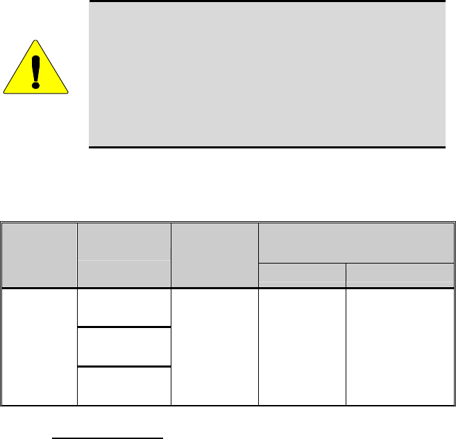
CAUTION
Table 2-1 lists the recommended minimum lateral distance
for a controlled environment and for unaware bystanders in
an uncontrolled environment, from transmitting types of
antennas (i.e., monopoles over a ground plane, or dipoles) at
rated radio power for mobile radios installed in a vehicle.
Transmit only when unaware bystanders are at least the
uncontrolled recommended minimum lateral distance away
from the transmitting antenna.
Table 2-1: Rated Power and Recommended Minimum Safe Lateral
Distance
RECOMMENDED SAFE MINIMUM
LATERAL DISTANCE FROM
TRANSMITTING ANTENNA
MOBILE
RADIO
FREQUENCY
SPLIT
ANTENNA P/N
RATED POWER
OF VEHICLE-
INSTALLED
MOBILE TWO-
WAY RADIO CONTROLLED UNCONTROLLED
MAMV-AN3J
MAMV-AN3K
760 -870
MHz
MAMV-AN3V
15W 32 cm 70cm
2.2.1 Mobile Antennas
Install the radio’s antenna (refer to Table 2-1 for applicable antenna part
numbers) in the center of the vehicle’s roof. These mobile antenna installation
guidelines are limited to metal body motor vehicles or vehicles with
appropriate ground planes. The antenna installation should additionally be in
accordance with the following.
1. The requirements of the antenna manufacturer/supplier included with the
antenna.
2. Instructions in the M7200 Radio Installation Manual, including minimum
antenna cable lengths.
3. The installation manual providing specific information of how to install
the antennas to facilitate recommended operating distances to all
potentially exposed persons.
Use only the M/A-COM approved/supplied antenna(s) or approved
replacement antenna. Unauthorized antennas, modifications, or attachments
could damage the radio and may violate FCC regulations.
9

10
2.2.2 Approved Accessories
This radio has been tested and meets the FCC RF guidelines when used with
the M/A-COM accessories supplied or designated for use with this product.
Use of other accessories may not ensure compliance with the FCC’s RF
exposure guidelines, and may violate FCC regulations.
For a list of M/A-COM approved accessories refer to the product manuals,
M/A-COM’s Products and Services Catalog, or contact M/A-COM at 1-800-
368-3277.
2.2.3 Contact Information
For additional information on exposure requirements or other information,
contact M/A-COM, Inc. at 1-800-528-7711 or at http://www.macom-
wireless.com.

3 OPERATION SAFETY RECOMMENDATIONS
3.1 TRANSMITTER HAZARDS
WARNING
The operator of any mobile radio should be aware of certain
hazards common to the operation of vehicular radio
transmitters. A list of several possible hazards is given:
• Explosive Atmospheres – Just as it is dangerous to fuel a vehicle with
the motor running, similar hazards exist when operating a mobile radio.
Be sure to turn the radio off while fueling a vehicle. Do not carry
containers of fuel in the trunk of a vehicle if the radio is mounted in the
trunk.
Areas with potentially explosive atmosphere are often, but not always,
clearly marked. Turn OFF your radio when in any area with a potentially
explosive atmosphere. It is rare, but not impossible that the radio or its
accessories could generate sparks.
• Interference to Vehicular Electronics Systems – Electronic fuel
injection systems, electronic anti-skid braking systems, electronic cruise
control systems, etc., are typical electronic systems that can malfunction
due to the lack of protection from radio frequency energy present when
transmitting. If the vehicle contains such equipment, consult the dealer
and enlist their aid in determining the expected performance of electronic
circuits when the radio is transmitting.
• Electric Blasting Caps – To prevent accidental detonation of electric
blasting caps, DO NOT use two-way radios within 1000 feet of blasting
operations. Always obey the “Turn off Two-Way Radios” signs posted
where electric blasting caps are being used. (OSHA Standard: 1926-900)
• Liquefied Petroleum (LP) Gas Powered Vehicles – Mobile radio
installations in vehicles powered by liquefied petroleum gas with the LP
gas container in the trunk or other sealed-off space within the interior of
the vehicle must conform to the National Fire Protection Association
standard NFPA 58 requiring:
¾ The LP gas container and its fittings.
¾ Outside filling connections shall be used for the LP gas container.
¾ The LP gas container shall be vented to the outside of the vehicle.
3.2 SAFE DRIVING RECOMMENDATIONS
(Recommended by AAA)
• Read the literature on the safe operation of the radio.
11
12
• Keep both hands on the steering wheel and the microphone in its hanger
whenever the vehicle is in motion.
• Place calls only when the vehicle is stopped.
• When talking from a moving vehicle is unavoidable, drive in the slower
lane. Keep conversations brief.
• If a conversation requires taking notes or complex thought, stop the
vehicle in a safe place and continue the call.
• Whenever using a mobile radio, exercise caution.

4 OPERATING RULES AND REGULATIONS
Two-way FM radio systems must be operated in accordance with the rules and
regulations of the local, regional, or national government.
In the United States, the M7200 Series mobile radio must be operated in
accordance with the rules and regulations of the Federal Communications
Commission (FCC). As an operator of two-way radio equipment, you must be
thoroughly familiar with the rules that apply to your particular type of radio
operation. Following these rules helps eliminate confusion, assures the most
efficient use of the existing radio channels, and results in a smoothly
functioning radio network.
When using your two-way radio, remember these rules:
• It is a violation of FCC rules to interrupt any distress or emergency
message. As your radio operates in much the same way as a telephone
“party line,” always listen to make sure that the channel is clear before
transmitting. Emergency calls have priority over all other messages. If
someone is sending an emergency message – such as reporting a fire or
asking for help in an accident – KEEP OFF THE AIR!
• The use of profane or obscene language is prohibited by Federal law.
• It is against the law to send false call letters or false distress or emergency
messages. The FCC requires that you keep conversations brief and
confine them to business. To save time, use coded messages whenever
possible.
• Using your radio to send personal messages (except in an emergency) is a
violation of FCC rules. You may send only those messages that are
essential for the operation of your business.
• It is against Federal law to repeat or otherwise make known anything you
overhear on your radio. Conversations between others sharing your
channel must be regarded as confidential.
• The FCC requires that you identify yourself at certain specific times by
means of your call letters. Refer to the rules that apply to your particular
type of operation for the proper procedure.
• No changes or adjustments shall be made to the equipment except by an
authorized or certified electronics technician.
NOTE
Under U.S. law, operation of an unlicensed radio transmitter
within the jurisdiction of the United States may be punishable
by a fine of up to $10,000, imprisonment for up to two (2)
years, or both.
13
14
4.1 OPERATING TIPS
The following conditions tend to reduce the effective range of two-way radios
and should be avoided whenever possible:
• Operating the radio in areas of low terrain, or while under power lines or
bridges.
• Obstructions such as mountains and buildings.
• In areas where transmission or reception is poor, some improvement can
be obtained by moving a few yards in another direction or moving to a
higher elevation.

15
5 PRODUCT DESCRIPTION
The M7200 series digital mobile radio is a hardware component of the
OpenSky® network, an integrated voice and data communications system that
delivers end-to-end digital transmissions over a single wireless network to the
dash-mounted or trunk-mounted radio receiver.
Table 5-1 lists the available configurations of the M7200 mobile radio. This
manual covers the M7250 operation.
Table 5-1: M7200 Series Configurations
MODEL DESCRIPTION
M7250 Full Duplex Transceiver with CH-103 Control Head
M7270 Full Duplex Transceiver with CH-721 Control Head
(Future)
The M7250 is intended to operate in a mobile environment, typically a motor
vehicle. The radio operates in the 700 MHz and 800 MHz Specialized Mobile
Radio (SMR) and National Public Safety Planning Advisory Committee
(NPSPAC) frequency bands. The M7250 operates full-duplex with 10 W
(typical) transmit output power, and half-duplex with 15 W transmit output
power.
The M7250 is available in four hardware configurations, three of which are
further defined for data operation as half- or full-duplex:
• Dash mount with built-in control head. Additional remote control heads
can be added (half- or full-duplex).
• Trunk mount with a single or multiple remote control heads (half- or full-
duplex).
• Data only – No control head (half- or full-duplex, PC required).
The M7250 uses Time Division Multiple Access (TDMA) technology to
allow multiple users to share a single RF channel. In addition, a single RF
channel can support simultaneous digital voice and data communications.
The M7250 provides integrated voice and data services. Voice operation is
provided using a microphone and speaker included in the radio installation kit.
For data transfers, the M7250 is constructed with an industry-standard RS-232
interface serial port for connecting an optional laptop PC.
A PC, not included with the M7250, provides network connectivity through
the standard serial (DTE-type) interface.
The M7250 is a “soft” radio. Its functions are determined by the software
applications installed.
16
The optional GPS tracking devices embedded in M7250 radios can provide
quick and accurate positional information to a connected laptop locally in the
vehicle. GPS can also provide positional information over the radio link, if
configured to do so.
Unlike most dispatch radio systems, however, an active transmission can be
pre-empted by a dispatcher or supervisor. This results in the transmitting radio
instantly switching to receive the “priority” in-bound call. Normal operation
can be resumed once the in-bound call is concluded.
5.1 VOICE OPERATION
The voice path operates like a traditional dispatch radio, with a microphone to
transmit (push-to-talk) and a speaker to receive. In OpenSky Trunked Protocol
(OTP), there is no separate voice and data path – all transmitted information is
digital.
5.2 DATA OPERATION
Data operation requires the connection of a laptop PC. OpenSky works
through standard IP protocols such as UDP/IP. The data path operates
similarly to the voice path, with a few differences. All external data
information in and out of the radio uses the RS-232 serial port connection.
5.3 REMOTE CONTROL HEAD OPERATION
For remote mount installations configured with a CH-103 control head, all
normal radio operations and interfaces can be made remotely from the radio
unit via the remote control head connected to the radio unit by a single
twisted-pair connection that is easy to route through a vehicle. Up to six
control units may be attached to a trunk mount radio. Each control head
provides a serial access point for data and any one (only one at a time) of
these can be connected to a data device such as a personal computer.
Where multiple control heads are connected, or where a dash-mount radio is
installed with additional remote control heads, several other features are
available from each position:
• Outgoing voice calls can be initiated. (Any control head can initiate a call
but only one can talk at a time. All other connected control heads will
hear both sides of the conversation.)
• Incoming and outgoing audio can be heard. (Outgoing audio is not
broadcast at the source position.)
• Independent audio control is available.
• Radio settings such as talk group, scan mode etc., can be controlled. (Any
connected control head can override the radio settings of other connected
control heads.)

17
• Comfort settings, such as volume and display brightness that are
applicable to the individual control head can be adjusted and cannot be
overridden by other control heads.
• An optional intercom function is available between control units. (Audio
will be broadcast to ALL connected control heads.)
5.4 INTERCOM OPERATION
The intercom option, a licensed option, allows the M7250 radio to pass audio
locally between control heads and not over the network. It gives users at
multiple control heads connected to the same radio the ability communicate
with each other without transmitting over-the-air. When activated, incoming
network radio calls are still scanned and broadcast at each control head.
5.5 PERSONALITY
As illustrated in Figure 5-1, a personality defines the profiles and talk groups
available to the user. It is the structuring of a collection of profiles and
privileges established by the OpenSky network administrator to provide the
user with a comprehensive set of profiles to communicate effectively with the
necessary talk groups or individuals.
Personalities are stored on the network and downloaded over-the-air to the
radio. This process is called “provisioning.” Provisioning occurs at radio
power-up and at user log-in. Each personality can contain up to sixteen (16)
profiles and each profile can contain up to sixteen talk groups.
5.5.1 Profiles
As stated above, each profile can contain up to sixteen (16) talk groups. A
profile also defines the radio’s emergency behavior. All transmissions are
made on the selected talk group (displayed on the top line of the dwell
display). The user can change the selected talk group to any of the other talk
groups within the profile.
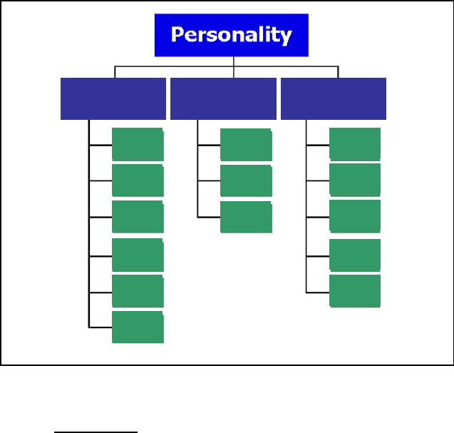
TG a
TG b
TG c
TG x
TG y
TG z
TG d
TG e
TG f
TG a
TG d
TG g
TG h
TG i
TG = Talk Group
Profile 1 Profile 2 Profile 3
Figure 5-1: Personality Structure Example
5.5.2 Talk Groups
A talk group represents a set of users that regularly need to communicate with
one another. There can be any number of authorized users assigned to a talk
group. Talk groups are established and organized by the OpenSky network
administrator. An OpenSky talk group is similar to a channel within a
conventional FM radio system.
5.6 GPS OPTION
The radio can be equipped with an optional Global Positioning System (GPS)
receiver. Utilized with a micro-patch antenna, this option allows the user to
track his/her coordinates and report these to central dispatch when within
range of an OpenSky network. See page 56 for additional information.
18
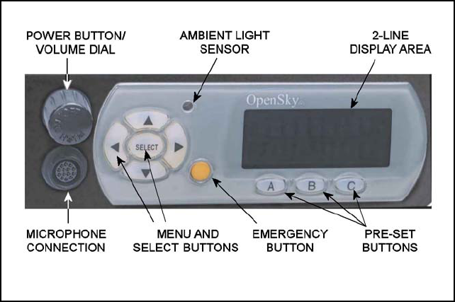
5.7 CH-103 FRONT PANEL
The CH-103 front panel provides the interface for the operator. It includes a
19-character (8 over 11) vacuum fluorescent display, navigation and select
buttons for menu navigation, three pre-set buttons, a power button/rotary
volume control knob, a microphone connector, and an emergency button.
In addition, the front panel contains a light-level sensor that samples ambient
light levels for automatic display and button backlight brightness adjustments.
In other words, it automatically brightens the display and backlights when
higher external light levels exist and it automatically dims the display and
backlights during lower external light levels.
Figure 5-2: CH-103/103PA Front Panel
19
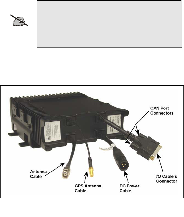
5.8 TRANSCEIVER REAR PANEL
The rear panel of the transceiver is shown in Figure 5-3. It contains most of
the radio’s cable connections. The DC power connector accepts vehicle
battery power to power the radio and an ignition/accessory control sense
input. The I/O connector contains the speaker output connections and optional
connections, including NMEA-formatted GPS output data if the optional GPS
receiver is installed in the radio. A serial port is provided for connection to a
standard serial (DTE-type) device such as a mobile data terminal. An antenna
port connection is also available for connecting a GPS antenna if the optional
GPS receiver is installed in the radio. If not, a nylon plug is inserted into this
hole. Connection to a CAN1 device such as the CH-103 control head is made
through the 3-pin CAN connector.
NOTE
The radio uses a nominal amount of battery power when it
is turned off. If the vehicle in which the radio is installed
is likely to be left unused for extended periods of time,
M/A-COM recommends installing Time-Delay Relay (p/n
MAMROS0088) to prevent excessive vehicle battery
drain.
Finally, the TX/RX mini-UHF connector (half-duplex) provides connection
for an RF antenna and the RX port is capped with a nylon plug. For full-
duplex radios, the RX port has a TNC connector output and both RF ports and
antenna are connected through an RF combiner.
Figure 5-3: Transceiver Rear Panel
1 Controller Area Network—a type of digital interface used to transfer control data and digitized
voice data between the mobile radio and control head(s) connected to it.
20
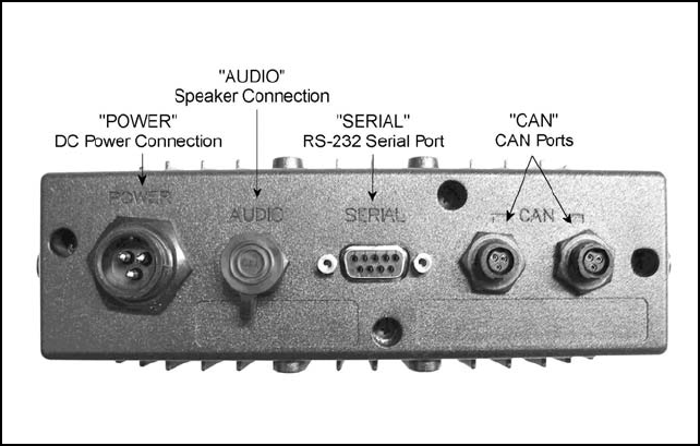
5.9 CONTROL HEAD REAR PANEL
The rear panel of the CH-103 control head contains the interface connections
necessary between the radio and control unit. As shown in Figure 5-4, five
connection points are:
• POWER - The DC power connector accepts vehicle battery power to
power the unit and an ignition/accessory control sense input for on/off
control via the vehicles ignition switch/key.
• AUDIO – Provides connection to an external speaker.
• SERIAL – A serial port is provided to transfer data to and from a mobile
data terminal or PC. It is configured as a DTE device.
• CAN – The two 3-pin CAN connectors are used to connect the CH-103 (a
CAN device) to the M7250 and to other control heads. These two
connectors are connected in parallel to allow daisy chaining of additional
control heads. A terminator (supplied) must be connected to the unused
CAN port of the last control head.
Figure 5-4: CH-103 Control Head Rear Panel
21
6 OPERATION
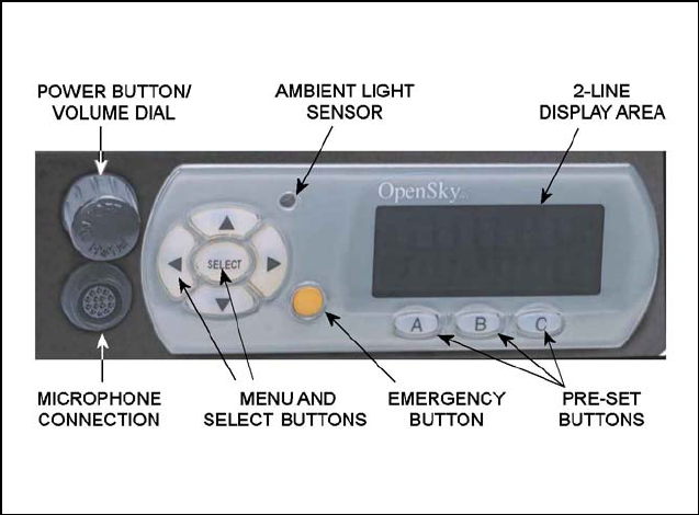
6.1 CH-103 FRONT PANEL COMPONENTS
The front panel of the CH-103 control head includes a 19-character 2-line
display, menu and select buttons for menu navigation, an emergency button,
three pre-set buttons, a power button/rotary volume dial, a microphone
connector. See Figure 6-1. Table 6-1 lists all front panel controls and their
functions.
Figure 6-1: CH-103 Front Panel Components
The buttons on the front panel are backlit for operation in a low ambient light
level such as nighttime operation. Some buttons also flash to provide feedback
of various operating conditions.
In addition, the front panel contains a light-level sensor that samples ambient
light levels for automatic display and button backlight brightness adjustments.
In other words, it automatically brightens the display and backlights when
higher external light levels exist and it automatically dims the display and
backlights during lower external light levels.
22

23
Table 6-1: Front Panel Controls and Functions
PART FUNCTION
POWER
Button/Volume Dial
• Push to turn the radio on2.
• Push and hold for approximately one-half (0.5) of a
second3 to turn the radio off.
• Twist clockwise to increase volume.
• Twist counter-clockwise to decrease volume.
Mic Connection • Connect hand-held, hands-free, DTMF microphone,
speaker-mic, or headset here.
EMERGENCY button • Pressing the EMERGENCY button, if enabled
through programming, will send an emergency alert
and open voice communication on the currently se-
lected talk group or the default emergency talk
group (depending upon how the system is defined).
• To end an emergency call, press and hold the
emergency button for approximately four seconds.
AMBIENT LIGHT
sensor
• Radio automatically adjusts the display and button
backlight brightness level based on ambient light.
Do not block this sensor.
MENU and SELECT
buttons
• Cycle through the menu loop with UP and
DOWN buttons.
• Scroll through selections with LEFT and RIGHT
buttons.
• Press SELECT button to activate the current
selection. In some cases, this is not necessary as the
last selection will automatically activate after a short
period.
• The SELECT button flashes green when the radio is
receiving and red when the radio is transmitting.
DISPLAY area • Menu selections and messages.
• Network Connectivity icon (Figure 6-2)
• Current Volume Level icon (Figure 6-2)
♦ Volume numeric representation within the
display (0 = Muted, 40 = Loudest).
• User may select which one of several dwell displays
the radio uses.
PRE-SET buttons • These buttons are used to store and recall user-
selectable parameters such as scan mode, selected
profile, selected talk group, and priority talk group.
Different parameters can be stored at each of the
three different pre-set buttons.
2 The Power Button may be configured to function in different ways or be disabled altogether.
Refer to Section 6.3.1 for more detail.
3 The length of time necessary to hold the Power Button is configurable. The default time length is
one-half of a second.
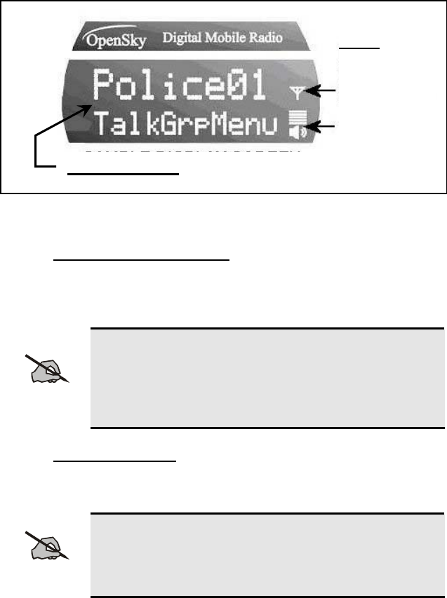
6.2 DISPLAY OVERVIEW
The display shows the radio status (Table 6-2). Network connectivity and
volume icons appear on the right. The volume level is also represented
numerically within the display with zero (0 or muted) being the lowest volume
level and forty (40) being the highest/loudest level. “Mute” displays when the
speaker is muted. The rest of the display consists of two text lines that change
in response to user interaction with the menu buttons. A sample display is
shown in Figure 6-2.
Figure 6-2: Sample Display (Talk group Menu Session)
24
6.2.1 Network Connectivity Icon
The illuminated network connectivity icon (refer to Table 6-2) indicates
network connectivity has been achieved. This icon will always be illuminated
when the powered radio is connected to the “network.”
NOTE
Transmitting voice communications may be possible even
if the Network Connectivity icon is not illuminated.
However, reception of voice calls from others and
transmitted audio to users on other radio sites is not
guaranteed while in this state.
6.2.2 Volume Level Icon
As shown in Figure 6-2, the volume level icon indicates the current
speaker/headset volume setting. Turn the volume dial to change the setting.
NOTE
In addition to the volume level icon at the right of the
display, volume level is also presented numerically within
the display. This numeric representation only appears
during, and briefly after, the volume adjustment is made.
Two Text Lines
Icons
Network
Connectivity
Volume Level
6.2.3 Display’s Top Line
The display’s top line of text changes as the and menu buttons are
pressed to scroll through the selections in the active menu. When the dwell
display is present, press the and buttons to scroll through available talk
groups. The top line of the display also indicates other information such as the
selected talk group, when the dwell display is active, and alert messages.
6.2.4 Display’s Bottom Line
The display’s bottom line of text changes as the c and d menu buttons are
pressed to scroll through the menus. The menu structure is shown in Figure
6-3 on page 27. The bottom line of the display also indicates other information
such as a login prompt, emergency status, and dwell display messages as
described in the following section.
6.2.5 Dwell Display
When not engaged in menu selection, the 2-line display defaults to the user-
defined default display, known as the “dwell display.” The top line indicates
the currently selected talk group. The bottom line indicates the currently
selected profile, received talk group/caller ID/alias4, or radio channel. To set
one of these bottom line options, press the Select button from the dwell
display.
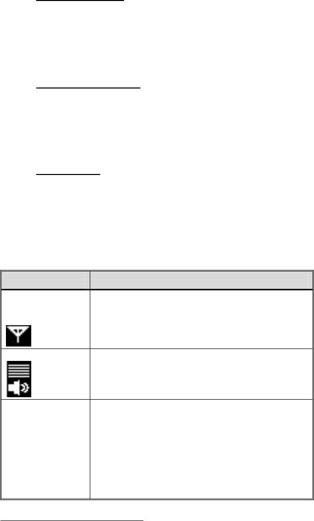
Table 6-2: Display Parts and Functions
COMPONENT FUNCTION
Network
Connectivity
Icon
When the network connectivity icon is illuminated,
there is a network connection and not illuminated
when there is no network connection.
VOLUME Icon
Shows current speaker volume setting chosen by the
user. Note that a momentary numerical
representation will also be shown within the display
while the volume is being adjusted.
TWO TEXT
LINES During a menu session, the display’s bottom line
responds to (up arrow) and (down arrow)
buttons. It indicates the current menu. For example,
the Talk group Menu is selected in Figure 6-4.
The display’s top line responds to the (left arrow)
and (right arrow) buttons. It indicates the options
within the current menu. For example, “Police1” is
the currently selected talk group in Figure 6-4.
25
4 Alias is a logical ID name such as “J_Smith.” The name corresponds to a user ID such as 003-
542-0001. Alias is limited to eight (8) characters.

26
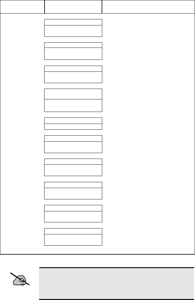
Menu Name Radio Displays
(top and bottom lines) Usage Notes
To/From Dwell Display (Bottom menu on page 27)
▲ ▼
registration, RF sync and
transceiver status codes
Engineering
Display
(Menu may not be avail-
able per programming.)
bit-error rates
and RSSI data
Displays radio system connection data.
For engineering use. See page 57.
▲ ▼
current latitude and
longitude (degrees:-
minutes:seconds)
GPS Fix
“GPS Fix”
Radio’s current GPS latitude and
longitude position scrolls across top line
of the display. Applies to GPS-equipped
radios only. See page 56.
▲ ▼
User ID # of user
currently logged in
User ID
“User ID”
User’s identification/name scrolls across
top line of the display (if programmed).
▲ ▼
Radio’s IP address
IP Address “IP Address”
Radio’s Internet Protocol (IP) address
scrolls across top line of the display.
▲ ▼
station’s call sign
Station
Identification “Station ID”
Station’s identification/name scrolls
across top line of the display (if
programmed).
▲ ▼
available modes
Operating Mode
(e.g., OTP, OCF) “Mode Menu”
Use ◄ or ► to turn choose an available
mode. Press Select and confirm (Y/N)
with ◄ or ► and Select again.
▲ ▼
“OFF”
Stealth Mode
(blanks display when on) “StealthMenu”
Use ◄ or ► to turn on. Press any button
to turn it off. See page 38.
▲ ▼
“LOW”, “MEDIUM”,
“MEDHIGH”, “HIGH”
Treble Level
“Treble Menu”
Use ◄ or ► to choose speaker/headset
treble level. Press Select to return to
dwell display. See page 37.
▲ ▼
“<< >>”
Display
Brightness “Bright Menu”
Use ◄ to dim and ► to brighten
backlighting. Press Select to return to
dwell display. See page 37.
▲ ▼
“OFF”, “LOW”, “MED”,
HIGH”
Side Tone Level
“Side Menu”
Use ◄ or ► to choose side tone level.
Press Select to return to dwell display.
See page 36.
▲ ▼
“ON” or “OFF”
Intercom “INTERCOM”
Use ◄ or ► to turn intercom on and off.
Press Select to return to dwell display.
See page 40.
▲ ▼
selected channel Selected Channel
(Menu may not be
available per radio
programming) “ChannelMenu”
Displays the current channel. Press
Select to return to dwell display.
▲ ▼
current scan mode
Scan Mode “ScnModeMenu”
Use ◄ or ► to turn scan on and off.
Press Select to return to dwell display.
See page 43.
▲ ▼
27
Menu Name Radio Displays
(top and bottom lines) Usage Notes
▲ ▼
talk group “<”
Talk group
Lock Out “LockOutMenu”
Use ◄ or ► to choose a talk group for
locking/unlocking. Press Select to toggle
“<” on (locked out) and off. See page 41.
▲ ▼
current priority talk group
Priority Talk group “PriTG Menu”
Use ◄ or ► to choose new priority talk
group. Press Select to return to dwell
display. See page 44.
▲ ▼
alert received
Emergency
Dismiss “EmgDismiss”
Use ◄ or ► to choose emergency talk
group. Press Select to dismiss. See
page 51.
▲ ▼
time/sender’s name/
alias/message text
Alerts Received “AlertsRecvd”
or oldest message
“No alerts” or alert message text scrolls
in display. Use ◄ to view older
messages and ► to view newer
messages. See page 47.
▲ ▼
alert received
Alert Message “AlertMsg”
Use ◄ or ► to choose message for
sending/transmitting. See page 45.
▲ ▼
current speed dial #
Alert Destination “AlertDest”
Use ◄ or ► to choose a speed-dial
number. Press Select to return to dwell
display. See page 45.
▲ ▼
current speed dial #
Speed Dial “SpeedDial”
Use ◄ or ► to choose a speed-dial
number. Press Select to return to dwell
display. See page 44.
▲ ▼
currently active profile
Profile Selection “ProfileMenu”
Use ◄ or ► to choose an available
profile. Press Select to return to dwell
display. See page 38.
▲ ▼
selected talk group
Talk group
Selection “TalkGrpMenu”
Use ◄ or ► to choose a talk group in
current profile. Press Select to return to
dwell display. See page 39.
▲ ▼
Selected talk group
Dwell Display (bottom line option)
Use ◄ or ► to scroll top line through
talk groups. Press Select to change
bottom line option. See pages 25 & 28.
Use ▲ (up arrow) and ▼ (down arrow) to scroll through menus.
Figure 6-3: Basic Menu Structure
NOTE
Menus will vary depending upon system
programming, radio hardware, and optional
configurations. See the NOTE on the next page for
details.
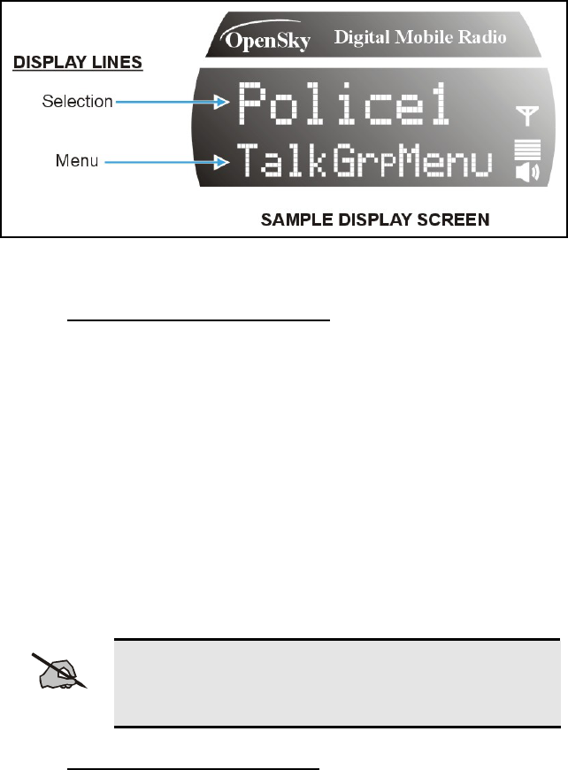
Figure 6-4: Top and Bottom Display Lines
6.2.6 Menu Display and Control Area
Following power-up, the radio display shows the default talk group. Pressing
the c and d buttons change the display to the next available menu. Refer to
Figure 6-3: Basic Menu Structure. In many cases, the dwell display
automatically re-appears after no menu buttons are pressed for a short period
of time (between 10 and 30 seconds). For some menus such as the GPS Fix
and User ID menus, this does not occur until the user presses a front panel
button.
When the dwell display is active, it will change dynamically to reflect the
current profile, received talk group/caller ID (when available), or channel
(when enabled).
The radio’s display is highly interactive. It responds in the top and bottom text
lines as the user presses the menu buttons (c, d, ◄, ► and Select) to scroll
through the menu loop and the entries for each menu.
NOTE
Although the radio display supports eight (8) characters
on the top line, systems currently limit talk group names
to seven (7).
6.2.7 Dwell Display User-Selectable
The top line of the dwell display for OpenSky trunked mode operation is
always the selected talk group for the profile of the particular radio. What
appears in the bottom line depends on the choice made as a dwell display
option. From dwell display, press Select to change the bottom line display
option by cycling through available options.
Whatever the preference, the radio will respond dynamically to changes in
status, always displaying the current information about the current network
connection. The bottom line indicates the currently selected profile, received
talk group/caller ID/alias, or radio channel. To set one of these bottom line
28
options, press the Select button from the dwell display. If a menu is not
enabled it is not available for display in the bottom line of the dwell display.
Figure 6-3 shows the Basic Menu Structure and some options available.
Available profiles, talk groups, and channels vary widely from network to
network depending on system hardware, and option configuration.
NOTE
Visible menu items will vary depending on the system,
hardware, and option configuration.
6.3 BASIC RADIO OPERATION
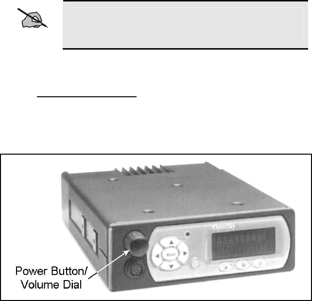
6.3.1 Turning the Radio On
1. If set-up to turn the radio on and off, press the Power Button/Volume
Dial as indicated in Figure 6-5. The display will illuminate when the
radio powers up. However, the Power Button portion of this control can
be configured in another way as described in the following NOTE.
Figure 6-5: Power Button/Volume Dial
2. Wait for the power-up sequence to complete, which takes approximately
ten (10) seconds.
During this time, if enabled for auto registration, the radio is provisioned
with a customized user personality designed for the user’s specific needs
by the OpenSky network administrator.
If this personality contains encrypted talk groups or if the user is
authorized for, and intends to use, manual encryption, User Login must
be performed. This requires a microphone with a DTMF keypad so that
the User ID and password can be entered.
29


31
NOTE
Shipped from the factory, the Power Button will need to be
pressed a first time. It can then be configured to function in
other ways. In most cases, the particular way is established
during radio installation. The possibilities are:
A. Turn the radio on and off by pressing the button.
B. The button is disabled and the radio is turned on and
off power with the vehicle’s ignition key/switch.
C. The button is disabled and the radio is turned on and
off with a panel or dash-mounted switch (e.g., a toggle
switch). Radio on/off power control is completely
independent of the vehicle’s ignition key/switch. This
configuration is not recommended. If the radio is
installed in this manner, it should be used with caution,
as excessive battery drain can occur if the radio is left
on for an extended period when the vehicle’s engine is
not running.
D. A combination of power button control and ignition
key/switch on/off power control (i.e., much like a
standard car radio). For example, when the radio is
turned off using the power button prior to turning the
vehicle off using the ignition switch/key, it will not
automatically turn back on when the vehicle is re-
started. However, if the radio is left on when the
vehicle is turned off, it will turn on and off with the
vehicle’s ignition key/switch. Unlike a standard car
radio, and for public safety purposes, it is possible to
turn the radio on while the vehicle is turned off.
E. A setting can be changed to adjust the amount of time
it takes for the radio to turn off to help prevent
accidental press of the power button from turning the
radio off. For example, a setting of two (2) seconds
will require the power button be pressed and held for
two seconds to turn the radio off. This feature is only
available for the on-to-off transition.
F. In multiple control head installations, the radio powers
up when the first control head is turned on, and it
powers down when the last control head is turned off.
The radio has a power-off timer that, if enabled,
automatically turns the radio (and control heads, if any) off
after a period of no use (i.e., lack of button presses, voice or
data transmissions, etc.) The timer’s period is pre-
programmed by the system or network administration
personnel. Incoming voice traffic is not considered; in other
words, these calls do not reset the automatic power-off
timer.

6.3.2 Self-Test
After power-up, the M7250 radio undergoes a multi-function automatic
registration procedure. As many as sixteen (16) possible radio profiles are
downloaded to the radio from the network in response to the User’s ID.
The M7250 mobile radio conducts a diagnostic Built-In Self-Test (BIST).
This test is a battery of hardware diagnostic tests on the internal components
of the Mobile Radio Unit (MRU). All processor and memory elements,
interfaces, connectivity elements, and RF functionality are analyzed for
operational integrity.
6.3.3 “Logging In” to the Network
Pushing the Power Button/Volume Dial will supply power to the radio (unless
configured otherwise as noted in section 6.3.1). Login occurs either
automatically (auto registration) if the radio has a valid registration or, if
enabled and authorized for encryption (section 6.11), requires the user to enter
a User ID and password.
If encryption is enabled and authorized on the radio, the user will be prompted
to “Pls Login” with the *1 login command, a User ID, and password (DTMF
microphone required, see section 6.10).
1. Press *1 (Login command).
2. Enter the full 10-digit User ID.
3. Press the # key.
4. Enter the password. See the following NOTE.
• If the radio is configured for alpha-numeric passwords and the
password has consecutive duplicate numbers (“MES33” for
example), enter # between the consecutive duplicate numbers so the
radio will not interpret the entry as a letter (“D” in this example).
• If the radio is configured for numeric-only passwords, do not enter #
between duplicated numbers.
5. Press the # key twice.
The User ID may be remembered from the previous log-in. (Refer to Section
6.3.4 for further details regarding log-off commands.) The password will be
established before the radio is put into operation. Contact the local OpenSky
network administrator for more information.
NOTE
If necessary, contact radio system administration personnel
for log-in assistance and/or radio-specific log-in
instructions.
32
6.3.4 Logging off the Network
The *0## command de-registers the radio. Typically, it is automatically
performed when correctly powering down the radio (i.e., not just
disconnecting the radio from vehicle power). Using this method, the User ID
is remembered by the radio so only the password is needed at next log-in. To
manually log-off, press *0## on the DTMF microphone’s keypad.
If a user is logged in using encryption features, it is necessary to log-off when
encryption is no longer required.
6.3.5 Turning the Radio Off
To turn the radio off, push and hold the Power Button/Volume Dial for
approximately one-half of a second (exact time is configurable). The radio’s
display fades to darkness. In a multiple control head installation, turning off
the last powered-up control head will also automatically turn off the radio.
Several user-selected radio settings (i.e., scan mode, volume, pre-set buttons,
and side tone levels) are maintained for the next operational session. At the
next radio power-up, maintained settings will automatically restore, along
with the network personality settings. In multiple control head installations,
settings are maintained for each control head position.
NOTE
If power is abruptly disconnected from the radio prior to
executing the correct turn-off procedure, user-selected radio
settings and last-tuned channel information will be lost.
This can extend the time required for the radio to register
with the network upon the subsequent power-up.
6.3.6 Receiving and Transmitting Voice Calls
As soon as the radio completes the startup/log-on/provision/self-test sequence
and registers on the OpenSky network, voice calls from talk groups in the
active profile will be audible.
6.3.6.1 Receiving a Voice Call
No action is required to receive a voice call. The display responds to incoming
voice calls as follows:
• If the dwell display is set to received talk group/caller ID/alias, the
display indicates either the User ID of the incoming caller, if available, or
the talk group’s name. If the selected talk group matches the receive talk
group, caller ID/alias is displayed. Otherwise, the talk group (name) is
displayed.
• If the dwell display is not set to received talk group, the display indicates
the data appropriate to those displays, but provides no indication as to the
identity of the incoming caller.
33

34
Refer to section 6.6 for detailed information on talk group scanning. Refer to
section 6.11 for detailed information regarding sending and receiving
encrypted calls.
6.3.6.2 Transmitting a Voice Call
Transmit a voice call as follows:
1. If not already, turn the radio on. See section 6.3.1 beginning on page 29 if
necessary.
2. If required, log-in to the network using a user ID and password. See
section 6.3.3 beginning on page 32 as necessary.
3. Select the desired talk group for transmitting on.
4. Depress and hold the Push-to-Talk (PTT) button on the hand-held
microphone, pause for a moment, and then speak normally. For maximum
clarity, hold the microphone approximately 1 ½ inches from the mouth
and do not shout or whisper into it. If the call is queued by the network,
wait for the grant tone to sound before speaking.
5. Release the PTT button when finished speaking.
Refer to section 6.11 for detailed information regarding sending and receiving
encrypted calls.
6.3.7 Radio Tones
In addition to the volume level tones (sounded momentarily only when
volume level is adjusted) and confirming tones (sounded momentarily when a
menu or option is selected), the radio provides nine (9) other tones. These
tones provide feedback to the user about whether the radio is able to transmit
on the channel when the PTT button is pressed and are described below.
1. Deny Tone
If the radio is not able to access the channel when PTT is pressed, the
radio will issue three short beeps, all of the same pitch, as the deny
indication. The radio will issue the deny tone when the PTT is pressed if
it is out of coverage, if the requested talk group is already active, or if the
channel is busy. The user must release the Push-to-Talk button and re-key
the PTT to make another call request.
2. Queued Tone
If the radio site is currently fully occupied with calls, a new call request
may be queued by the system. The radio issues three tones, a low-pitched
tone followed by two mid-pitched tones, to indicate the call has been
placed in a queue. The user may release PTT at this point. When
resources are available, the radio begins transmitting, the grant tone
sounds, and the user must press PTT within five (5) seconds to hold the
call up.

35
3. Grant Tone or Go-Ahead Tone
This feature must be enabled as part of the radio configuration to be
active. When resources become available for a call request placed in the
queue the grant tone sounds (if enabled) upon channel access. It is a short
single tone beep. The user should press and hold the PTT button and
begin speaking.
4. Removed Tone
After access to the radio channel has been granted and the user is
transmitting, the radio may be pre-empted by a high priority call or by
loss of coverage. The removed tone is a single long low-pitched tone,
which notifies the user that access to the channel has been lost. When the
removed tone is heard, access to the channel has been lost and the radio is
no longer transmitting, even if the PTT button is being pressed. The PTT
button must be re-keyed to regain channel access.
5. Start Emergency/Emergency Call Received
When an emergency call is initiated, all users configured to receive
emergency call notification and the initiator of the call will hear three (3)
short high-pitched tones.
6. Emergency Cleared Tone
When an emergency call has been initiated, the initiator of the call can
clear the call by pressing and holding the emergency button until the
emergency cleared tone (one long low-pitched) sounds. This tone sounds
identical to the removed tone.
7. Emergency Alert Tone
This tone sounds when an emergency alert is declared. It is three (3) short
beeps.
8. Selective Call Ring Tone
When a selective call is placed, a ringing tone is heard at the called radio
similar to that of a telephone. The ringing is repeated every four (4)
seconds until the call is accepted or rejected by the radio being called or
until the network drops the call if unanswered after one (1) minute.
9. Selective Alert Received Tone
When a selective alert is received, the radio will emit a series of four
short tones: low, high, low, low. The four tones are only played once to
indicate a selective alert has been received.
10. Roam Tone
The roam tone is a quick high-low beep sequence that sounds when the
radio transitions from one radio base station site to another. If this tone
sounds just after pressing the PTT button, keep the PTT button depressed
and begin speaking into the microphone after the grant tone sounds.
11. PSTN Ring Tones
There are two ring tones. One is generated by the radio when there is an
incoming telephone call or an outgoing telephone call attempt is waiting

for the telephone interconnect gateway equipment to dial the Public
Switched Telephone Network (PSTN). This is a single medium-pitch
reiterative tone. The second ring tone sounds when the gateway
equipment has dialed the number. It is a digital recreation of the actual
ring from the PSTN telephone line.
6.3.8 Adjusting Side Tone Audio Level
The radio sounds confirming tones called “side tones” when its buttons are
pressed. Most users find this audible confirmation helpful when navigating the
menus. Side tone audio level can be adjusted or turned completely off using
the “Side Menu.”
For covert operations, it may be necessary to turn off side tones. For safety’s
sake, turning off the radio during covert operations is not recommended.
WARNING
Neither activating Stealth Mode nor turning side tones
off will eliminate the tones sounded when adjusting the
volume of the radio. Use volume control with caution
when operating covertly.
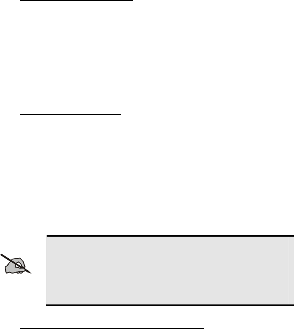
To temporarily disable the side tones that could expose the user’s presence
and position, use the menu buttons to access the “Side Menu” and select “Off”
from the menu choices (Figure 6-7).
If the radio is operating properly but side tones are not heard when the menu
buttons are pressed, the side tones are probably turned off. To turn them back
on, access the “Side Tone” menu and select a setting other than “off.”
Use the following procedure set side tone level:
1. Use the ▲ and ▼ buttons to cycle through the menu until the “Side
Menu” appears in the bottom line of the display.
2. Use the ◄ or ► buttons to change to the desired level (Off, Low,
Medium, High). To turn side tones completely off, use the “Off” setting.
3. Press the Select button to confirm and begin using the side tone level
setting. The dwell display will appear when the radio begins using the
new setting.
36
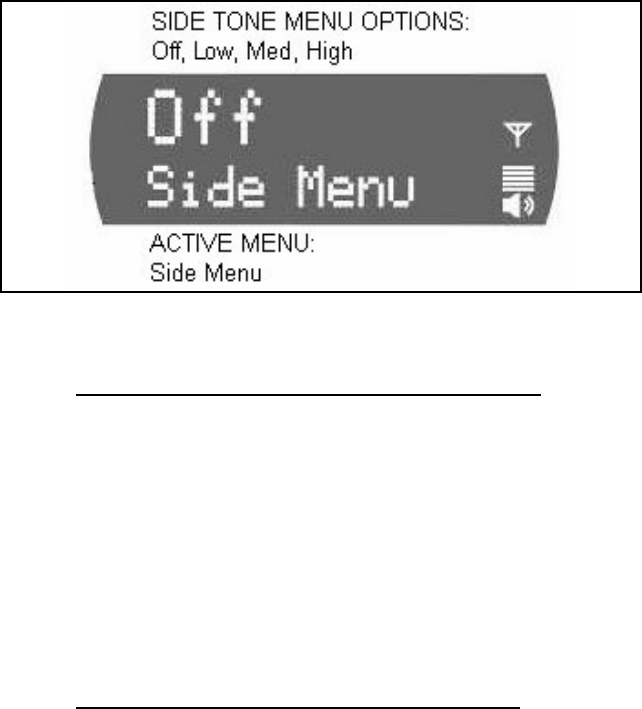
Figure 6-7: Side Tones Menu
6.3.9 Adjusting Display & Button Backlight Brightness
The radio uses a light sensor on the front panel to automatically adjust display
brightness and button backlight brightness to ambient light conditions. The
display and backlights automatically brighten at higher external light levels
exist and automatically dim at lower external light levels. However, the
“Bright Menu” gives the user some manual brightness control as follows:
1. Use the ▲ or ▼ button to scroll through the menu until “Bright Menu”
appears. A “<< >>” symbol appears in the top line of the display.
2. Use the ◄ button to reduce the brightness or the ► button to increase the
brightness. Display and button backlight brightness will immediately dim
or brighten.
6.3.10 Adjusting Speaker/Headset Audio Treble Level
The tone of received signals heard in the speaker and headset can be adjusted
using the radio’s “Treble Menu” as follows:
1. Use the ▲ or ▼ button to scroll through the menu until “Treble Menu”
appears. The radio’s current treble level setting indicates in the top line of
the display. There are four (4) levels available: low, medium, medium-
high and high.
2. Use the ◄ button to reduce the treble level setting or the ► button to
increase it.
3. Press the Select button to return to the Dwell Display.
37

6.3.11 Stealth Mode
The radio’s display illumination and button backlighting can be completely
turned off using stealth mode. Turn stealth mode on and off as follows:
1. Use the ▲ and ▼ buttons to cycle through the menu until “StealthMenu”
appears.
2. To immediately turn stealth mode on, press either the ◄ button or the ►
button once.
3. To turn stealth mode off, press any button on the radio’s front panel.
When stealth mode is on, the radio continues to scan the programmed list of
talk groups and the user can key-up on the selected talk group.
NOTE
With stealth mode on, pressing any radio button other than
the mic’s PTT button or the emergency button on front
panel will immediately turn stealth mode off. For
example, pressing the ▼ button on the front panel will
turn stealth mode off.
6.3.12 Checking or Changing the Active Profile
The radio can store up to sixteen (16) standard profiles within its personality,
one of which is always set as the currently active profile. Each profile can
contain up to sixteen (16) talk groups. Each profile is typically configured to
contain those talk groups specific to certain communication activities, such as
police patrol.
If the dwell display is set to “profile,” the currently active profile’s name
appears in the bottom line of the display. Otherwise, to determine which
profile is currently active, use the menu buttons to access the Profile Menu.
The active profile’s name will appear in the top line of the display. To switch
to/activate a different profile:
1. Press the c or d button until “ProfileMenu” appears in the bottom line
of the display. The name of the currently active profile appears in the top
line. For example, “TacNet” as shown in Figure 6-8.
2. Press the ◄ or ► buttons to choose the desired profile stored in the radio
as established by the OpenSky network administrator.
3. Press the Select button to activate the newly chosen profile. After a short
time (a few seconds), the newly chosen profile activates and the dwell
display re-appears.
38
Figure 6-8: Profile Menu
6.3.13 Checking or Changing the Selected Talk Group
Each profile stored in the radio can have up to sixteen (16) talk groups. One
talk group within the currently active profile is set as the “selected talk
group.” For the radio user, the selected talk group is typically the focus of
most voice transmissions and receptions. There are two ways to change the
selected talk group:
First Method:
1. Use the ▲ and ▼ buttons to scroll through the menu until
“TalkGrpMenu” appears on the bottom line of the display. The currently
selected talk group appears in the top line of the display. For example,
“Police1” as shown in Figure 6-9.
2. Use the ◄ or ► buttons to scroll through the available list of talk groups
in the active profile. This list is determined by the OpenSky network
administrator.
OR
Second Method:
1. From the dwell display, press the or buttons to scroll through the
available list of talk groups in the active profile.
39
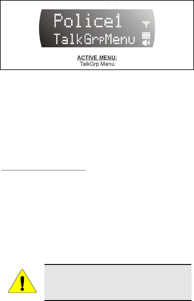
Figure 6-9: Talk Group Menu
6.4 INTERCOM MODE
The optional intercom mode gives users at multiple control heads connected to
the same radio the ability communicate with each other without transmitting
over-the-air. Turn intercom mode on and off using the “INTERCOM” menu
as follows:
1. Use the c and d buttons to cycle through the available menu items until
“INTERCOM” appears in the display.
2. Use the ◄ or ► buttons to toggle between “On” and “Off.”
When intercom mode is turned on:
• Incoming voice calls will override intercom communications for the
duration of the voice call. The radio and associated control heads will
remain in intercom mode and intercom communications will resume
when the voice call ends.
• “TG: INTERCOM” appears in the control head’s display when talking on
the intercom. This indicates microphone audio is not sent out on the
selected talk group; rather, it remains localized between the radio control
positions (i.e., the control heads connected to the mobile radio).
• If a call exists on the currently selected talk group when a PTT button is
pressed at one of the control heads, “TG: in use” appears in the display to
indicate intercom mic audio cannot preempt the call on the talk group.
CAUTION
A user at a radio with only one control head/front panel
can turn intercom mode on. In this case, pressing the
microphone’s PTT button will not send microphone
audio anywhere.
40
6.5 TALK GROUP LOCK OUT
There are two ways of focusing voice communications by suppressing calls
from talk groups in the currently active profile:
1. No Scan. By turning scan off (selecting “No Scan” via the
“ScnModeMenu”), only the selected talk group is audible.
2. Lock Out. By locking out selected talk groups, the “chatter” of the
locked-out talk groups cannot be heard. This focuses the user’s scanning
resources to calls only on desired talk groups.
Talk group lock out is a scan-related feature. With lock out, one or more talk
groups in the active profile can be temporarily disabled from being scanned.
Calls are not received on locked-out talk groups. Lock out settings are not
retained between profile changes or when the radio is power cycled.
NOTE
Lock out is a listening (receive) function and only blocks
received calls on locked out talk groups. Lock out does
not affect transmit capability. The above methods do not
apply to recent emergency lock outs.
Only talk groups in the active profile can be locked out, since they are the
only talk groups whose voice calls can be heard on the radio.
NOTE
The currently selected talk group, the default emergency
talk group, or emergency-capable talk groups CANNOT
be locked out.
In addition, if a talk group is locked out and is
subsequently changed to the currently selected talk
group, it will automatically be unlocked by the radio so
the user can hear calls on the talk group.
The radio may be configured so all except the default
emergency and other emergency-capable talk groups are
automatically locked out by default. In this case, they
must be manually unlocked, if desired.
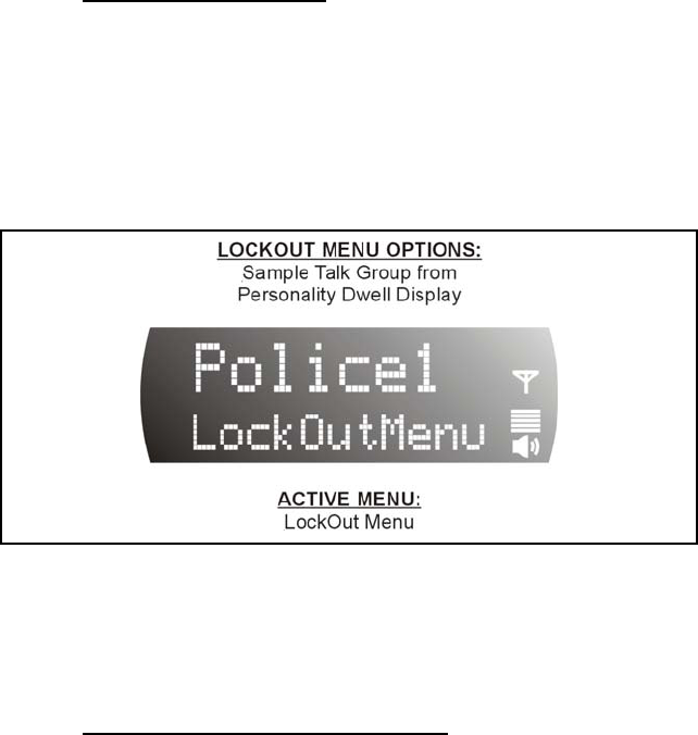
6.5.1 Locking Out a Talk Group
1. Use the ▲ or ▼ button to scroll through the menu until “LockOutMenu”
appears in the bottom line of the display. The name of a talk group in the
currently active profile will appear in the top line. See Figure 6-10.
2. Use the ◄ or ► buttons to scroll through the list of talk groups, if any,
until the desired talk group for lock out appears in the top line of the
display.
41
3. Press the Select button to lockout the displayed talk group. A less than
symbol (<) appears next to the talk group’s name.
4. Repeat steps 3 and 4, as needed, to lockout additional talk groups.
The dwell display will re-appear a few seconds after button presses end.
While scrolling through talk groups in the active profile, the only talk groups
that appear in the “LockOutMenu” are those in the active profile.
6.5.2 Unlocking a Talk Group
1. Use the ▲ or ▼ button to scroll through the menu until “LockOutMenu”
appears in the bottom line of the display. The name of a talk group in the
currently active profile will appear in the top line. See Figure 6-10.
2. Use the ◄ or ► buttons to scroll through the list of talk groups, if any,
until the talk group desired for unlocking appears in the top line of the
display. A less-than symbol (“<”) appears next to the name of a talk
group that is currently locked out.
Figure 6-10: Lock Out Menu
3. Press the Select button to unlock the talk group. The less-than symbol
(“<”) next to the name of the talk group disappears. The dwell display
appears as soon as the radio acknowledges the selection.
6.5.3 Caution Regarding Profile Changes
A talk group’s lock out status does not survive a change of profile. If after
locking out talk groups in the current profile and then selecting a new profile,
all talk groups that were previously locked are automatically unlocked.
Compare options before changing to another profile. If the user’s goal can be
achieved by temporarily assigning priority talk group status to a talk group, it
could be possible to avoid having to lock out the same talk groups again in a
new profile. See the section entitled Changing Priority Talk Group on page
44 for additional information.
42

43
6.6 SCAN MODE
Two scanning modes are available for the radio, but only one can be active at
any time. Changing the scanning mode changes the way the radio scans voice
calls for all of profiles in the radio personality, no matter which profile is or
becomes active.
As described in Table 6-3, the choice of scanning mode broads or narrows the
span of communications with all the talk groups in the radio’s profiles, but
does not affect interaction with the talk groups.
Table 6-3: Scan Modes
SCAN MODE EXPLANATION
No Scan Eliminates distractions.
Full communications (transmit and receive) on
selected talk group.
No calls received from other talk groups.
Normal
(Default)
Full communications (transmit and receive) on the
selected talk group.
Scans all talk groups in the active profile that are
not locked out.
Receive calls from more than one talk group, if
available from the current site.
Allows dragging of the selected and default
emergency talk groups to the site on which the radio
is registered. (If other calls are available at the site,
they also can be heard but they will not be actively
dragged.)
An emergency-enabled talk group is only dragged if
it is in emergency mode.
6.6.1 Checking or Changing Active Scan Mode
The currently active scan mode does not appear in the dwell display. To check
it, access “ScnModeMenu” and observe it in the top line of the display. To
change the active scan mode, access “ScnModeMenu” and select the other
mode as described in the following section.
6.6.1.1 Changing Scan Mode
1. Use the ▲ and ▼ buttons to scroll through the menus until
“ScnModeMenu” appears in the display.
2. Use the ◄ or ► buttons to scroll through the scan options until the
desired mode appears. See Table 6-3.

6.6.2 Changing Priority Talk Group
When scanning, the default emergency talk group has the highest scan priority
(1st), followed by the currently selected talk group (2nd), a talk group set as the
priority talk group (3rd), followed by other talk groups in the currently active
profile that are not locked out. Follow this procedure to set a talk group in the
current profile as the priority talk group:
1. Use the ▲ or ▼ button to scroll through the menu until “PriTG Menu”
(Priority Talk group) appears in the bottom line of the display. The talk
group currently set as the priority talk group appears in the top line of the
display.
2. Use the ◄ or ► button to select a new priority talk group.
3. Press the Select button to set the newly selected talk group as the priority
talk group.
6.7 SELECTIVE CALL
Selective calling is a feature that allows two radio units to obtain and utilize
an independent voice path for a private call. Radios can be configured to both
initiate and receive selective calls or to only receive selective calls.
In the OpenSky system, a source radio can be configured to initiate selective
calls through a pre-programmed list in memory. This method uses the “speed
dial list” set up by the OpenSky network administrator and provisioned as part
of the registration process.
In addition, a properly equipped source radio can initiate a selective call to
any radio in the system by entering the ten-digit voice user ID (which looks
like a telephone number) of the target device. Entering a selective call number
without using the speed dial feature requires an optional DTMF microphone.
See section 6.10 for more detail.
NOTE
Selective calls are terminated if an emergency is
declared.
6.7.1 Making a Selective Call
Use the keypad on the microphone to input digits to place the call. If the radio
is not equipped with a keypad microphone, use the ▲ or ▼ buttons to scroll
through the menu until “SpeedDial” appears in the bottom line of the display.
44

NOTE
Speed dial numbers are defined and provisioned by the
OpenSky network administrator and cannot be manually
entered into the radio by the user. Contact the
administrator if changes to the speed dial list are
required.
1. If using the microphone’s DTMF keypad:
A. Press *8 on the keypad.
B. Enter the number of the radio to be called (e.g., 027-001-0006). Like
dialing a telephone number, ignore/do not enter dashes. If the region
number (first 3 digits; 027 in this example) is the same as this radio’s
region number, these digits do not need to be entered. Likewise, if
the region and agency numbers (first 6 digits; 027-001 in this
example) are the same as this radio’s numbers, these digits do not
need to be entered. Leading zeros can also be ignored.
C. Press and release the # key.
D. Wait approximately two (2) seconds.
E. Press and release the PTT button to initiate the selective call request.
When the called party accepts the call, press the PTT again and begin
speaking.
If using the buttons on the front of the radio:
A. Scroll through the Menu options using the ▲ and ▼ buttons until
“SpeedDial” appears in the bottom line of the display.
B. Using the ◄ and ► buttons, scroll through the pre-programmed
speed-dial numbers until the desired number appears in the display.
2. Continue by pressing the PTT button when speaking (transmitting) to the
caller.
3. To end the call, press the Select button.
6.7.2 Receiving a Selective Call
When someone calls in from another radio using the selective call function a
ring will sound in the speaker and/or headset. Press the ► button to answer
the call and press the microphone’s PTT button when speaking (transmitting)
to the caller. Press the Select button to end the call.
A selective call will be interrupted if an emergency is declared on a monitored
talk group.
6.7.3 Selective Alert
Selective alert messaging is an OTP feature allowing one of up to eight (8)
pre-programmed text messages (refer to section 6.7.3.6) to be sent from one
45

46
radio to another. The user specifies a destination radio’s User ID, selects one
of the pre-programmed text messages, and then transmits it to the destination
radio. The message delivery system adds time-of-day information and
forwards the message to the destination (receiving) radio. The sending radio
receives a brief message noting the status of the transmission. Refer to Table
6-4 for a list of possible status messages.
The first few characters of a message are part of the message text entered
when the message is programmed. This programming is performed by the
system or network administration personnel.
Messages successfully received by the destination radio are stored in it until
read or until it is power cycled.
6.7.3.1 Specifying the Destination
The destination radio’s User ID can be selected via the menu buttons on the
radio’s front panel or via the keypad on the DTMF microphone if the radio is
so equipped:
Menu Button Method
1. Using the ▲ or ▼ button, scroll through the menu until “AlertDest”
(Alert Destination) appears in the bottom line of the display. The current
speed dial number scrolls on the top line.
2. Press the ◄ or ► button to change to a different speed-dial number.
Pause between each arrow button depress to observe the entire number as
it scrolls across the top line of the display.
3. When the desired speed-dial number appears, press the Select button to
activate the selection.
4. Continue with section 6.7.3.2.
Keypad Method (DTMF Microphone Required)
To select the destination radio’s User ID using the keypad, perform the
following:
1. Press *7 on the keypad. “AlertDest” appears in the display.
2. Enter the number of the destination radio (e.g., 027-001-0006) using the
DTMF keypad. Like dialing a telephone number, ignore/do not enter
dashes. If the region number (first 3 digits; 027 in this example) is the
same as this radio’s region number, these digits do not need to be entered.
Likewise, if the region and agency numbers (first 6 digits; 027-001 in this
example) are the same as this radio’s numbers, these digits do not need to
be entered. Leading zeros can also be ignored. Refer to Section 6.10.
3. Press the # key to enter the number.
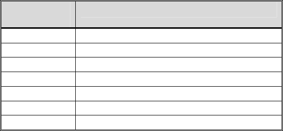
47
6.7.3.2 Choosing and Sending the Message
After specifying the destination radio’s User ID (section 6.7.3.1), the radio
automatically allows you to choose a message. The current message scrolls
across the top line of the display. To choose a message:
1. Scroll through the message list using the ◄ or ► button. The next
available message in the list is displayed. Pause between each arrow
button depress to observe the entire message as it scrolls across the top
line of the display.
If the destination radio’s User ID was chosen via the keypad on the
DTMF microphone, the keypad’s 4 and 6 buttons can also be used to
scroll through the available messages.
2. To select and send the displayed message, press the Select button, or
press the # button on the keypad.
3. The status of the sent message will be momentarily displayed. Possible
status messages and their meanings are listed in Table 6-4.
Table 6-4: Selective Alert Status Messages
STATUS
MESSAGE DEFINITION
Delivering Select Alert message transmit attempt
Congested Too busy – Try again
Dest Down Receiving radio not logged on – Not registered
Not Reg Transmitting radio not logged on – Not registered
Delivered Transmission complete
Unreach No response
Partial Transmission interrupted
6.7.3.3 Receiving Messages
When a selective alert message is received by a radio, a four-beep tone is
heard and “NewAlert” flashes until the new message is read. Up to eight (8)
received messages are stored. If another message is received, the first (oldest)
message automatically deletes to make room for the new incoming.
6.7.3.4 Displaying Received Messages
1. Using the ▲ or ▼ button, scroll through the menu until “AlertsRecvd”
(Alerts Received) appears in the bottom line of the display. “No alerts” or
the last received (newest) message appears in the display. It is preceded
by the time the message was received, and the sender’s name/alias.
2. View other received messages using the ◄ and ► buttons. Use ◄ to
view older messages and ► to view newer messages.
48
3. To delete the message currently being viewed, press the Select button.
6.7.3.5 Deleting Received Messages
To delete a received message:
1. Display the message (refer to Section 6.7.3.4).
2. Delete the message by pressing the Select button.
3. Confirm the deletion by pressing the Select button again.
6.7.3.6 Defining Pre-Programmed Messages
All selective alert messages are pre-defined by the radio system’s maintenance
personnel. These messages are sometimes referred to as “canned” messages.
Custom selective alert messages cannot be created by the radio user. The
entire selective alert message, including the abbreviation, can include up to
two hundred (200) text characters.
6.8 TELEPHONE INTERCONNECT CALLS
If the radio system is equipped with Public Switched Telephone Network
(PSTN) interconnect equipment, telephone calls can be made from the
M7250’s DTMF microphone using this procedure:
1. Press the *9 keys.
2. Enter the telephone number. (Ignore dashes/spaces, and precede the
number with any required access digits such as a 1 for long distance.)
3. Press the # key.
4. Wait a few seconds and then press and release the mic’s PTT button to
initiate the call. An initial ring tone plays indicating call initiation. Once
the gateway picks up the call, the ring tone changes.
5. When the caller answers, depress the PTT button when speaking and
release it to listen to the caller.
6. To hang-up, press the Select button on the front panel.
6.9 EMERGENCY COMMUNICATIONS
The M7250 mobile radio can transmit both emergency voice calls and
emergency alerts over the entire network. OpenSky handles emergency calls
and alerts with the highest priority.
For critical voice communications, an emergency call can be raised on the
default talk group or the currently selected talk group by “declaring” an
emergency on the talk group. The exact talk group is determined by the
currently active profile. After successfully declaring an emergency on a talk
group, the declaring radio’s microphone remains “hot” for a predetermined
amount of time. In other words, the radio transmits audio for a period of time

49
even when the microphone’s PTT button is not depressed. An emergency talk
group is provided greater priority and infinite hang-time by the radio system’s
infrastructure. Hang-time is the maximum duration of quiet time between
transmissions on the talk group before the infrastructure assets are
automatically taken away. Because an emergency call is handled on a talk
group, it is received by all radios and consoles monitoring the talk group.
An emergency alert is a data message sent by the radio to the MIS console (or
any console capable of receiving it). It identifies the radio declaring the
emergency, and the radio’s location (if the radio is equipped with a GPS
receiver). Voice audio is not automatically transmitted during the emergency
if the administrator configures the radio for alert notification only.
6.9.1 Declaring an Emergency Call or Alert
To declare an emergency call or emergency alert, press and release the orange
Emergency button. This button is located just to the right of the 5-button
Menu and Select keypad; see Figure 6-1 on page 22. Note the following:
• The OpenSky network administrator determines if the Emergency button
is used to declare an emergency call or if it is used to declare an
emergency alert. This is based upon the radio’s currently active profile.
• The OpenSky network administrator also determines if the emergency is
declared on the currently selected talk group or a “default” emergency
talk group. Again, this is based upon the radio’s currently active profile.
A talk group upon which an emergency is declared on is considered an
“emergency talk group.”
• Upon successful emergency declaration:
• An emergency tone will sound in the radio’s speaker/headset if the
radio is not in stealth mode.
• At the declaring radio, the Emergency button flashes red if the radio
is not in stealth mode. The administrator can configure the radio to
automatically transmit upon successful emergency declaration, at
which point the Select button will flash red. However, the Select
button flashing red is not a requirement for successful emergency
declaration.
• For an emergency call declaration, “EMERGENCY” indicates in the
bottom line of the display. In addition, the emergency talk group’s
name appears in the top line of the display, followed by an asterisk
(*). The emergency talk group can be forwarded across the OpenSky
network for emergency communications.
• For an emergency alert declaration, “EMERG ALERT” indicates in
the bottom line of the display.

50
• For an emergency call declaration, other radio users and/or
dispatchers at consoles will hear the emergency signal, a distinctive
3-tone burst. They will also hear audio from the declaring radio’s
“hot” microphone, if any.
• For an emergency alert declaration, only dispatchers at consoles will
hear the emergency signal and, if any, audio from the declaring
radio’s “hot” microphone.
• For an emergency call the declaring radio’s microphone remains
“hot” for a predetermined amount of time. In other words, the radio
transmits audio for a period of time even when the microphone’s
PTT button is not depressed. Audio is transmitted over the
emergency talk group. When the microphone is “hot” for this initial
period (typically ten seconds), simply speak into it for voice
transmission.
If an emergency declaration is not successful, the radio will periodically re-
attempt until it is successful. During this retry period, the radio will flash
“EMERG PEND” on the bottom line of the display. It will display “EMERG
RETRY” for each attempt.
6.9.2 Clearing an Emergency Call or Alert
To clear an emergency, press and hold the Emergency button for at least three
(3) seconds. However, this can only be accomplished at the radio where the
emergency was originally declared (the initiating radio), by a dispatcher at a
console, at a supervisory radio, or by the network administrator. When the
emergency is successfully cleared, the remove tone will sound at the initiating
radio. Also, for an emergency call, the asterisk (*) will clear from the display.
6.9.3 Receiving an Emergency Call
Upon receiving an emergency call declared by another radio:
• An emergency tone sounds in the radio’s speaker/headset (three short
high-pitched beeps).
• “EMERGENCY” flashes in the display if the radio is not in stealth mode.
• When the emergency talk group is selected, an asterisk (*) follows its
name in the top line of the display. The asterisk identifies the selected talk
group is in an emergency state. Some radios may be programmed by the
system or network administration personnel to flash the Emergency
button (red) when an emergency call is received. This occurs only if the
radio is not in stealth mode.
• If scan mode is set to “No Scan” and the emergency was declared on the
selected talk group, audio on the emergency talk group is heard in the
speaker/headset. See page 43 for additional information on “No Scan”
operation. Also see the following NOTE.
• If scan mode is set to “No Scan” and the emergency was declared on a
talk group other than the selected talk group, the emergency talk group
(identified by an “*”) must be selected before audio on it is heard in the
speaker/headset.
• If scan mode is set to “Normal” and the emergency was declared on the
selected talk group, the selected/emergency talk group’s name remains in
the top line of the display. Audio on the emergency talk group is heard in
the speaker/headset.
• If scan mode is set to “Normal” and the emergency was declared on a talk
group other than the selected talk group, the emergency talk group’s
name appears in the bottom line of the display. Audio on the emergency
talk group is heard in the speaker/headset.
• The declaring radio's alias appears in the bottom line of the display when
the emergency talk group is selected.
• An emergency call can be dismissed as described in the following section.
NOTE
A radio declaring an emergency on a talk group has a
“hot” mic time period of typically ten (10) seconds just
after it declares the emergency. This time period may be
adjusted by system or network administration personnel
on a per radio basis.
6.9.4 Dismissing an Emergency Call
To ignore an emergency call declared by another radio user, dismiss it as
follows:
1. Press the▲ or ▼ button until “EmgDismiss” appears in the display.
2. Press the ◄ or ► buttons until the talk group in the emergency state
appears, as indicated by an asterisk (*) following the talk group’s name.
3. Press the Select button.
6.10 DUAL-TONE MULTI-FREQUENCY KEYPAD
Dual-Tone Multi-Frequency (DTMF) is the system used by touch-tone
telephones. DTMF assigns a specific tone frequency to each key so a
microprocessor can easily identify its activation. The radio supports DTMF
using a microphone with an alphanumeric keypad (see Figure 6-11). This
allows for specific tasks such as entering a user ID and password, or selective
calling.
When a key on the DTMF keypad is pressed, a single low-pitched tone will be
heard from the microphone. The key tones are not adjustable.
51
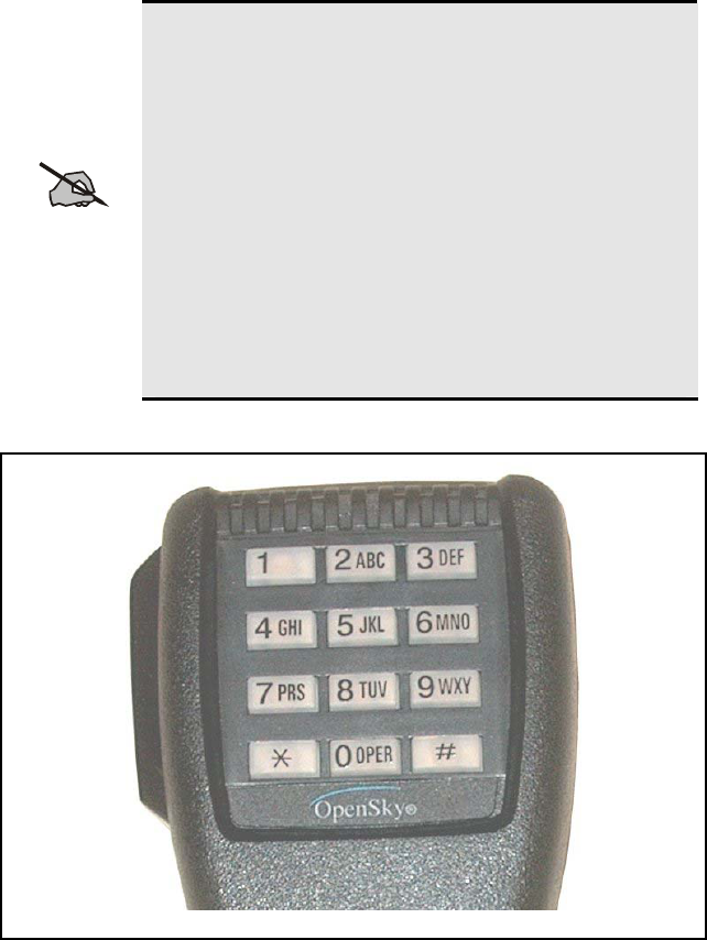
Although the “Q” is not shown on the 7 key, and the “Z”
is not shown on the 9 key of the DTMF keypad, both
letters are supported by the system. To enter a “Q” from
the keypad, press the 7 key 3 times (7, P, Q). To enter a
“Z” from the keypad, press the 9 key 5 times.
Because the Q and Z are recognized by the system, then
the number of presses to enter other characters from those
keys may be different. For instance, 5 key presses are
required to enter an “S” using the 7 key (7, P, Q, R, and
S).
If the key is pressed too many times, continue pressing the
key to scroll through the remaining characters and
returning to the first character. Remember to consider the
characters not shown on the keys.
52
NOTE
Figure 6-11: DTMF Microphone Keypad
To perform a command from the keypad, press the * key followed by one of
the pre-set function keys as follows:
*0 Log-off command: *0## (logs the user off the system). See page
33 for additional information.
*1 Log-in command: *1<User ID> # <Password> ## (required for
encryption). See page 32 for additional information.
*5 Single Site Channel command: *5<SMR/NPSPAC channel>#
*6 Load Default Personality command: *6#. This command
applies only if the radio is not voice-registered on the network.
*7 Initiate Selective Alert command: *7<Target ID>#[Choose
Message]#. See page 46 for additional information.
*8 Radio-to-Radio Call command: Selective call number # (PTT to
dial). See page 44 for additional information.
*9 Public Switched Telephone Network (PSTN) Call command:
See page 48 for additional information.
*32 Begin Manual Encryption command: *32<Pre-Determined
Encryption Key of Up To 16 Digits># See page 54 for additional
information.
*33 End Manual Encryption command: *33#.
NOTE
When entering letters or numbers from the keypad that has
if two or more adjacent characters represented by the same
key on the keypad, the pound (#) key must be pressed
after all but the last of the adjacent characters. For
example, to enter MACOM6, press the following keys: 6
key twice (M), 2 key twice (A), # key, 2 key 4 times (C),
6 key 4 times (O), # key, the 6 key twice (M), # key, and
then the 6 key once (6). Press the # key twice to complete
the entry.
6.10.1 Password Entry
Password entry requires a DTMF microphone. Password characters are
encrypted on the display using symbols to indicate the entry. The encryption
symbols for each entry will appear in the display as they are scrolled through,
for example: '-' and '+'. Press the # key twice to complete the entry process.
Refer to the above NOTE for more details.
If the radio is configured for alpha-numeric passwords and the password has
consecutive duplicate numbers (“MES33” for example), enter # between the
consecutive duplicate numbers so the radio will not interpret the entry as a
letter (“D” in this example). If the radio is configured for numeric-only
passwords, do not enter # between duplicated numbers.
53

NOTE
If the password is wrong, the radio will not successfully
register with the network for wide area voice reception.
The radio can still be used in single-site mode.
6.11 ENCRYPTION
In the OpenSky network, both data and voice use a 128-bit key encryption
standard published by the Federal Information Processing Service (FIPS),
called Advanced Encryption Standard (AES). AES is approved by the U.S.
Department of Commerce for encryption of classified materials.
When encryption is enabled on the network, data is encrypted from the MDIS
to the Mobile End System (MES) (e.g., M7250 mobile radio). This form of
encryption provides air-link security.
Voice encryption is handled either automatically or manually. Automatic
encryption is initiated through the Network Administration Server (NAS) for a
specific talk group and requires nothing from the user. Manual encryption is
initiated by two or more radio users and requires DTMF microphones. Both
methods of encryption are discussed in the following sections.
6.11.1 Automatic Encryption
For automatic encryption, a network administrator will select the talk group to
be encrypted at the interface to the NAS. Once the talk groups have been
selected and identified as secure, credentials for key generation are generated
automatically by the system and provisioned to authorized users. This process
requires that authorized users login to the network and be authenticated.
Encryption keys require no manual handling and are never sent “in the clear”
over any network interface or air-link.
1. “Pls Login” appears displayed in the bottom line of the dwell display.
2. Login normally using the DTMF microphone to enter User ID and
Password.
If a user is engaged in a call on a talk group encrypted at the network
administrator level, “Secure Call” will appear in the bottom line of the dwell
display if the user is logged in to that talk group.
If a secure call is in progress elsewhere and the user has not logged in, the
bottom of the dwell display will alternate between “No Access” and the alias
of the radio that is currently engaged in the secure call.
6.11.2 Manual Encryption
Two or more users can manually encrypt a call, if enabled, without an
established encrypted talk group. A pre-determined key and a DTMF
microphone are required at each radio.
54
NOTE
The key must be pre-determined by the users prior to
making a manually encrypted call on a talk group. It can
be between one and sixteen (1 - 16) digits and it is entered
into the radio using the keypad on the DTMF microphone.
If two communicating radios have different (manually-
defined) keys, receive audio at each radio will sound
garbled.
With manual encryption enabled, unencrypted radio users on the talk group
can still make standard voice (unencrypted) calls on the talk group. However,
if an unencrypted user attempts to transmit on the talk group when one of the
encrypted users is already transmitting on the talk group, the unencrypted
radio will sound a deny tone and “No Access” will appear in the display. Also,
the encrypted user can hear standard unencrypted calls, but cannot respond
while still manually encrypted.
CAUTION
Do not set a talk group for manual encryption if it has
been set for encryption by the network administration
personnel.
Perform the following to transmit or receive manually encrypted calls:
1. Press *32 on the DTMF microphone keypad.
2. Enter the key (up to 16 digits).
3. Press the # key.
NOTE
Due to inherent qualities of the DTMF microphone, there
is a two (2) second delay between entering the encryption
key and manual encryption feature taking affect.
4. To end manual encryption, press *33#.
If a user is engaged in a call on a talk group that has been manually encrypted
at the radio level, the user will see “Secure Call” on the bottom of the dwell
display.
If a secure (encrypted) call is in progress, and the user has not entered the key,
the bottom of the dwell display will alternate between “No Access” and the
alias of the radio that is currently engaged in the secure call.
Once the user has terminated manual encryption, “UnSecure” appears
temporarily in the bottom line of the dwell display.
55
56
6.12 PRESET BUTTONS
The front panel contains three buttons labeled A, B, and C. By holding one of
these buttons down for approximately three (3) seconds, the following current
information is saved to the function of that button:
• Selected talk group
• Selected profile
• Selected priority talk group
• Lockouts
• Scan mode
• Intercom mode
When information has been saved to a preset, the button will be illuminated
green. If the button is not designated as a preset, it will be illuminated red.
Presets are saved and restored to/from non-volatile memory. Changing the
User ID (login in as a different user) will clear the presets, as they are stored
on a per-user basis. Changing control heads will not recall presets for the
previous control head.
6.13 DYNAMIC REGROUPING
Dynamic regrouping requires that the network administrator determine which
radio users should be formed into an impromptu talk group to respond to
particular emergency conditions.
The administrator will edit the personalities of the affected radios to include
an emergency profile and then page the affected radios to re-register with the
network to receive their edited personalities.
In response, affected radios automatically re-register to receive their edited
personalities. During re-registration, subscriber equipment will default to the
emergency profile selected by the administrator.
6.14 GPS COORDINATES
If the radio is equipped with a Global Positioning System (GPS) receiver, the
radio’s current latitude and longitude coordinates (“fix”) may be displayed
using the “GPS Fix” menu. The following procedure assumes a GPS antenna
is connected to the radio and it is receiving adequate signals from GPS
satellites:
1. Press the▲ or ▼ button until the “GPS Fix” menu appears in the bottom
line of the display. Current GPS coordinate latitude and longitude data
continuously scrolls in the top line of the display in a
degrees:minutes:seconds format.
2. Press the▲ or ▼ button to change to another menu.
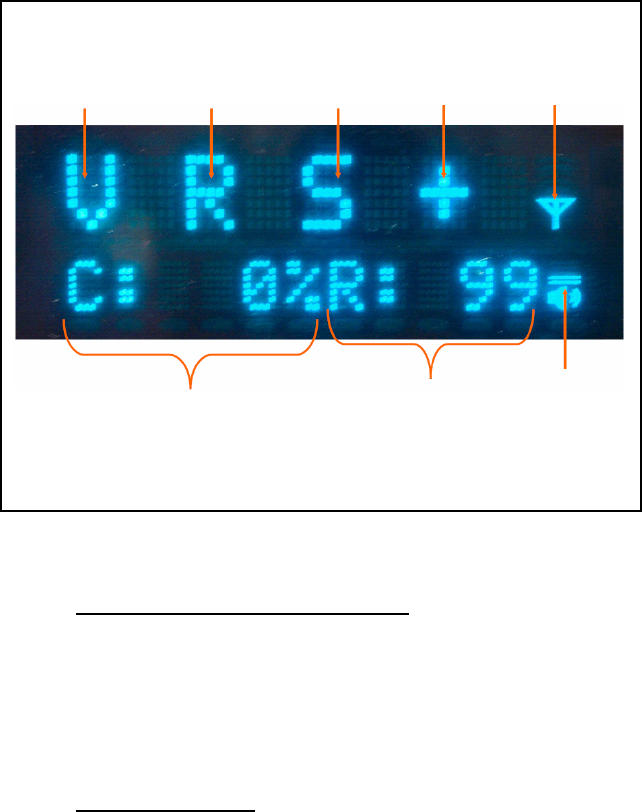
6.15 ENGINEERING DISPLAY
Some radios may have access to an engineering display that presents various
data related to the radio system. An example display is shown in the following
figure. Typically, this display is accessed by pressing the ▼ button once from
the dwell display.
57
RF Synchron-
ization
(“S”=Synchro-
nized)
Transceiver
Status
(See
below.)
Network
Connec-
tivity Icon
Voice Registra-
tion Code
(See Table 6-5)
Data Registra-
tion Code
(See Table 6-6)
Volume
Level Icon
Receive Signal
Strength
Indication
(RSSI)
(See page 62)
Control Block
Symbol Error
Rate (CBSER)
(See page 60)
Figure 6-12: Example Engineering Display
6.15.1 Voice and Data Registration Codes
The engineering display’s voice and data registration codes identify the
current registered operational status of the radio on the OpenSky network.
Voice registration is granted by the VNIC (Voice Network Interface
Controller) computer and data registration is granted by the MDIS (Mobile
Data Intermediate System) computer. See Table 6-5 and Table 6-6
respectively.
6.15.2 Transceiver Status
The engineering display’s transceiver status is a plus (“+”) symbol during
normal operations. If the radio is a full-duplex M7250, a status of “C”
indicates there is a problem with the radio’s RF combiner.

58
Table 6-5: Voice Registration Codes
DISPLAYED
CODE LOWER
DISPLAY RETRY MEANING
(none) (none) No Off network.
a VDENIED No Voice denied: Unknown reason.
b BAD VID No
Voice denied: Unknown MES ID.
(Check User ID.)
c (none) No Voice denied: Duplicate MES ID.
d (none) No Voice denied: IP address denied.
e (none) No Voice denied: Duplicate IP address.
f BAD PWD No Voice denied: Missing password.
g BAD PWD No Voice denied: Invalid password.
h HOM DWN Yes Voice denied: Home VNIC down.
i SRV BSY Yes Voice denied: Serving VNIC congested.
j (none) Yes Voice denied: Aged reg. seq. number.
k MAX USR Yes Voice denied: Too many login instances.
l NAS BSY Yes Voice denied: NAS changing talk group.
V (none) No Voice registered.
v (none) No Voice registration pending.
R (none) No Data registered only.
Table 6-6: Data Registration Codes
DISPLAYED
CODE LOWER
DISPLAY RETRY MEANING
R (none) No Data registered.
1 (none) No Network access denied. Unknown reason.
2 (none) No Network ID unsupported.
3 UNAUTH3 No Network ID not authorized. (Check IP.)
4 UNAUTH4 No Bad authentication.
5 UNAUTH5 No Unsupported authentication.
6 MDS BSY Yes MDIS fully loaded.
7 DUP IP No Service denied: Duplicated IP address.
p (none) No Data registration pending.
d (none) No Data deregistration pending.

59
6.15.3 Receive Signal Strength Indication (RSSI)
The engineering display’s RSSI number represents, in absolute value, the
dBm level of the signal received from the OpenSky’s base station transmitter.
It represents a negative unit of measure, but a negative/minus sign does not
precede the number in the display. Because the displayed number represents a
negative value, higher/increasing numbers represent lower/decreasing
received signal strengths.
Values lower than -110 (125 for example) indicate a possible antenna
problem, or radio operation in a fringe or no-coverage area.
Higher RSSI values, -85 for example (displayed 85), with CBSER values
greater than zero (0) generally indicate RF interference is being induced into
the receiver or radio’s antenna system along with the received signal.
It is not uncommon for an OpenSky signal with low RSSI and degraded
CBSER to be decoded by the radio and heard at the speaker without any
problem.
6.15.4 Control Block Symbol Error Rate (CBSER)
The engineering display’s CBSER value indicates data distortion or
interference. Zero (0) represents no errors. When operating in RF fringe areas,
this number may increase as interference in the received data signals
increases.

60
7 BASIC TROUBLESHOOTING
If the radio is not operating properly, check Table 7-1 for likely causes. For
additional assistance, contact a qualified service technician.
Table 7-1: Basic Troubleshooting
SYMPTOM CAUSE SOLUTION
Radio will not
turn on. No power. Test the connection to the
vehicle power supply.
Radio will not
turn off. If in multiple control head
configuration, one of the
attached control heads is
still powered up.
Power off all control
heads.
Radio will not
register or does
not receive
provisioning
data.
Bad logon credentials. Check logon and password.
No audio. Speaker volume is muted. Increase the volume level.
Poor audio. Transmitting or receiving
in a poor coverage area or
subject to interference.
Check network
connectivity and move to a
better coverage area if
possible. Report the area
without coverage to an
authorized network
technician.
Poor display
visibility. Ambient Light Sensor is
obstructed. Clear the obstruction and
give the sensor a clear path
to ambient light.
No network
connectivity
icon in display.
Radio is out-of-range or
cannot connect with the
OpenSky network.
Base station network
connection has failed.
Return to coverage area if
possible and wait for
condition to clear.
Use single-site trunking or
switch to an alternate
channel.
Radio will not
transmit. Radio may be out of
coverage area or may be
overheated.
Return to coverage area if
possible. If overheated, let
radio cool before retrying
transmission. Report this
failure to an authorized
technician.

61
SYMPTOM CAUSE SOLUTION
Radio will not
transmit
(transmit
indicator does
not flash).
Radio may be experiencing
low voltage. The M7250 will cease to
transmit if the voltage
drops below 8.5 volts.
Have the battery checked
by an authorized
technician.
Radio powers
off for no
apparent
reason.
Radio may be experiencing
very low voltage. The M7250 automatically
powers down when voltage
drops below +5.0 volts.
Have the battery checked
by an authorized
technician.
“Warning: No
MRU”
Message.
Radio control head is
unable to communicate
with mobile radio unit
(radio transceiver).
Have the radio connections
checked by an authorized
technician.
Control head
randomly
changes
display.
In multiple control head
configurations, another
user is operating the radio
from another control head.
None
Encrypted calls
cannot be
made.
Not authorized to use. Contact system
administrator to request
encryption privileges.
Encrypted calls
cannot be
made.
User not logged in. Log in (refer to Section
6.10.1).
62
8 WARRANTY
A. M/A-COM, Inc. (hereinafter "Seller") warrants to the original purchaser for use
(hereinafter "Buyer") that Equipment manufactured by or for the Seller shall be free from
defects in material and workmanship, and shall conform to its published specifications.
With respect to all non-M/A-COM Equipment, Seller gives no warranty, and only the
warranty, if any, given by the manufacturer shall apply. Rechargeable batteries are
excluded from this warranty but are warranted under a separate Rechargeable Battery
Warranty (ECR-7048).
B. Seller’s obligations set forth in Paragraph C below shall apply only to failures to meet the
above warranties occurring within the following periods of time from date of sale to the
Buyer and are conditioned on Buyer’s giving written notice to Seller within thirty (30) days
of such occurrence:
1. for fuses and non-rechargeable batteries, operable on arrival only.
2. for parts and accessories (except as noted in B.1) sold by Seller’s Service Parts
Operation, ninety (90) days.
3. for PANTHER™ Series handportable and mobile radios, two (2) years.
4. for all other equipment of Seller’s manufacture, one (1) year.
C. If any Equipment fails to meet the foregoing warranties, Seller shall correct the failure at
its option (i) by repairing any defective or damaged part or parts thereof, (ii) by making
available at Seller’s factory any necessary repaired or replacement parts, or (iii) by
replacing the failed Equipment with equivalent new or refurbished Equipment. Any
repaired or replacement part furnished hereunder shall be warranted for the remainder of
the warranty period of the Equipment in which it is installed. Where such failure cannot be
corrected by Seller’s reasonable efforts, the parties will negotiate an equitable adjustment
in price. Labor to perform warranty service will be provided at no charge during the
warranty period only for the Equipment covered under Paragraph B.3 and B.4. To be
eligible for no-charge labor, service must be performed at a M/A-COM factory, by an
Authorized Service Center (ASC) or other Servicer approved for these purposes either at
its place of business during normal business hours, for mobile or personal equipment, or
at the Buyer’s location, for fixed location equipment. Service on fixed location equipment
more than thirty (30) miles from the Service Center or other approved Servicer’s place of
business will include a charge for transportation.
D. Seller’s obligations under Paragraph C shall not apply to any Equipment, or part thereof,
which (i) has been modified or otherwise altered other than pursuant to Seller’s written
instructions or written approval or, (ii) is normally consumed in operation or, (iii) has a
normal life inherently shorter than the warranty periods specified in Paragraph B, or (iv) is
not properly stored, installed, used, maintained or repaired, or, (v) has been subjected to
any other kind of misuse or detrimental exposure, or has been involved in an accident.
E. The preceding paragraphs set forth the exclusive remedies for claims based upon defects
in or nonconformity of the Equipment, whether the claim is in contract, warranty, tort
(including negligence), strict liability or otherwise, and however instituted. Upon the
expiration of the warranty period, all such liability shall terminate. The foregoing
warranties are exclusive and in lieu of all other warranties, whether oral, written,
expressed, implied or statutory. NO IMPLIED OR STATUTORY WARRANTIES OF
MERCHANTABILITY OR FITNESS FOR PARTICULAR PURPOSE SHALL APPLY. IN
NO EVENT SHALL THE SELLER BE LIABLE FOR ANY INCIDENTAL,
CONSEQUENTIAL, SPECIAL, INDIRECT OR EXEMPLARY DAMAGES.
This warranty applies only within the United States.
M/A-COM, Inc. M/A-COM, Inc
1011 Pawtucket Blvd. 221 Jefferson Ridge Parkway
Lowell, MA 01853 Lynchburg, VA 24501
1-877-OPENSKY 1-800-528-7711
ECR-7047C
63

M/A-COM Wireless Systems
221 Jefferson Ridge Parkway
Lynchburg, Virginia 24501
(Outside USA, 434-385-2400) Toll Free 800-528-7711
www.macom-wireless.com
Printed in U.S.A.