HARRIS TR-0005-A UHF-FM Land Mobile Transceiver User Manual MAXIMUM PERMISSIBLE EXPOSURE MPE LIMITS

HARRIS CORPORATION UHF-FM Land Mobile Transceiver MAXIMUM PERMISSIBLE EXPOSURE MPE LIMITS

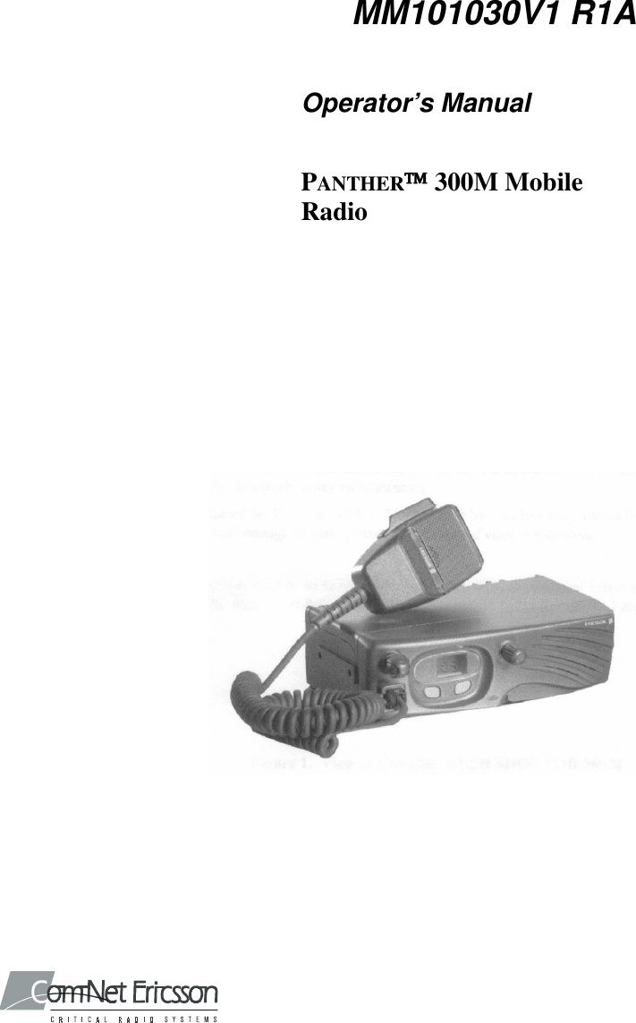
Operator Manual MM101030V1 R1A
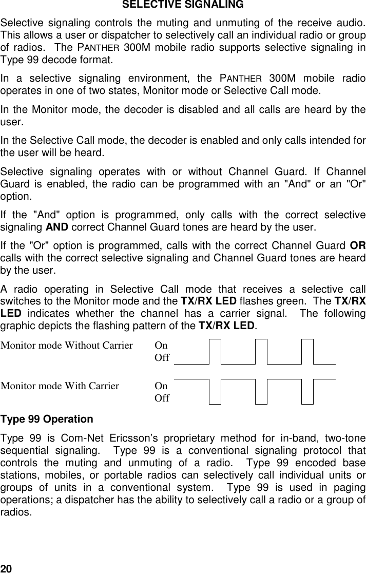
MM101030V1 R1AOperator’s ManualPANTHER 300M MobileRadio
2TABLE OF CONTENTSPageMAXIMUM PERMISSIBLE EXPOSURE (MPE) LIMITS............................................................... 3RADIO OPERATOR WARNING ............................................................................................................... 3SAFETY TRAINING INFORMATION............................................................................................... 4TRANSMITTER HAZARDS ..................................................................................................................... 6SAFE DRIVING RECOMMENDATIONS.................................................................................................... 7OPERATING RULES AND REGULATIONS.................................................................................... 8OPERATING TIPS .................................................................................................................................. 9INTRODUCTION................................................................................................................................ 10RADIO INDICATORS........................................................................................................................ 11CONTROLS ......................................................................................................................................... 11OPTION BUTTON FUNCTIONS............................................................................................................. 12HOOKSWITCH FUNCTIONS ................................................................................................................. 14DISPLAY STATUS AND ERROR CODES....................................................................................... 15BASIC OPERATION........................................................................................................................... 17SELECTING A CHANNEL .................................................................................................................... 17TRANSMITTING A BASIC CALL .......................................................................................................... 17PUBLIC ADDRESS MESSAGE............................................................................................................... 17CHANNEL GUARD .............................................................................................................................. 18SENDING DTMF WITH THE DTMF MICROPHONE............................................................................. 19SELECTIVE SIGNALING ................................................................................................................. 20TYPE 99 OPERATION ........................................................................................................................ 20PROGRAMMABLE PTT FUNCTIONS ........................................................................................... 22CHANNEL BUSY LOCKOUT................................................................................................................. 22CHANNEL GUARD CHANNEL BUSY LOCKOUT ................................................................................... 22TYPE 99 DISABLE AFTER PTT.......................................................................................................... 22IGNITION SENSE TX DISABLE............................................................................................................. 22PROGRAMMABLE HORN ALERT FUNCTION........................................................................... 23EXTERNAL ALARMS........................................................................................................................... 23RESETTING THE CAR HORN ALERT .................................................................................................... 23CAR HORN ALERT IGNITION SENSE OPTION ...................................................................................... 23CLONING............................................................................................................................................. 23This manual is published by Com-Net Ericsson Critical Radio Systems, Inc., without anywarranty. Improvements and changes to this manual necessitated by typographical errors,inaccuracies of current information, or improvements to programs and/or equipment, may bemade by Com-Net Ericsson Critical Radio Systems, Inc., at any time and without notice.Such changes will be incorporated into new editions of this manual. No part of this manual maybe reproduced or transmitted in any form or by any means, electronic or mechanical, includingphotocopying and recording, for any purpose, without the express written permission of Com-Net Ericsson Critical Radio Systems, Inc.Copyright © 2001, Com-Net Ericsson Critical Radio Systems, Inc.  All rights reserved.
3MAXIMUM PERMISSIBLE EXPOSURE (MPE) LIMITSRADIO OPERATOR WARNINGDo not transmit with this radio and antenna when persons are within theMPE Radius of the antenna, unless such persons (such as the driver or radiooperator) are shielded from the antenna field by a grounded metallic barrier(such as the user’s vehicle rooftop).  The MPE Radius is the minimumdistance from the antenna axis that persons should maintain in order to avoidRF exposure higher than the allowable MPE level set by the FCC.FAILURE TO OBSERVE THESE LIMITS MAY ALLOWTHOSE WITHIN THE MPE RADIUS TO EXPERIENCE RFRADIATION ABSORPTION WHICH EXCEEDS THE FCCMAXIMUM PERMISSIBLE EXPOSURE (MPE) LIMIT.  IT ISTHE RESPONSIBILITY OF THE RADIO OPERATOR TOENSURE THAT THE MAXIMUM PERMISSIBLEEXPOSURE   LIMITS   ARE   OBSERVED  AT   ALL  TIMESDURING RADIO TRANSMISSION.  THE RADIO OPERATOR IS TOENSURE THAT NO BYSTANDERS COME WITHIN THE RADIUS OFTHE MAXIMUM PERMISSIBLE EXPOSURE LIMITS SHOWN BELOW.Determining MPE RadiusTHE MAXIMUM PERMISSIBLE EXPOSURE RADIUS HAS BEENESTIMATED TO BE A RADIUS OF ABOUT 55 INCHES (OR 138 CM) FORTHE VEHICULAR MOUNTED ANTENNA SYSTEMS, AND 77 INCHES (OR195 CM) FOR BASE STATION MOUNTED ANTENNA SYSTEMS PER OETBULLETIN 65 OF THE FCC.  THIS ESTIMATE IS MADE ASSUMING THEMAXIMUM CAPABLE POWER OF THE RADIO IS TRANSMITTED ANDANTENNAS WITH A MAXIMUM GAINS OF 3 dBd ARE USED FORVEHICULAR MOUNTED SYSTEMS AND 6 dBd FOR BASE STATIONSYSTEMS.A MAXIMUM 50% TRANSMIT DUTY CYCLE IS ASSUMED, DUE TO THEPUSH-TO-TALK STATUS OF THIS MOBILE.
4SAFETY TRAINING INFORMATIONYOUR COM-NET ERICSSON PANTHER 300M MOBILERADIO GENERATES RF ELECTROMAGNETIC ENERGYDURING TRANSMIT MODE.  THIS RADIO IS DESIGNEDFOR AND CLASSIFIED AS “OCCUPATIONAL USEONLY” MEANING IT MUST BE USED ONLY DURINGTHE COURSE OF EMPLOYMENTBY INDIVIDUALS AWARE OF THE HAZARDS AND THE WAYS TOMINIMIZE SUCH HAZARDS. THIS RADIO IS NOT INTENDED FOR USEBY THE “GENERAL POPULATION” IN AN UNCONTROLLEDENVIRONMENT.  IT IS THE RESPONSIBILITY OF THE RADIOOPERATOR TO ENSURE THAT THE MAXIMUM PERMISSIBLEEXPOSURE LIMITS DETERMINED IN THE PREVIOUS SECTION AREOBSERVED AT ALL TIMES DURING TRANSMISSION.  THE RADIOOPERATOR IS TO ENSURE THAT NO BYSTANDERS COME WITHINTHE RADIUS OF THE MAXIMUM PERMISSIBLE EXPOSURE LIMITS.This radio has been examined and complies with the FCC RF exposure limitswhen persons are beyond the MPE radius of the antenna.  In addition, yourCom-Net Ericsson radio complies with the following Standards andGuidelines with regard to RF energy and electromagnetic energy levels andevaluation of such levels for exposure to humans:•  FCC OET Bulletin 65 Edition 97-01 Supplement C, EvaluatingCompliance with FCC Guidelines for Human Exposure to RadioFrequency Electromagnetic Fields.•  American National Standards Institute (C95.1-1992), IEEE Standard forSafety Levels with Respect to Human Exposure to Radio FrequencyElectromagnetic Fields, 3 kHz to 300 GHz.• American National Standards Institute (C95.3-1992), IEEERecommended Practice for the Measurement of Potentially HazardousElectromagnetic Fields – RF and Microwave.
5CAUTIONTO ENSURE THAT YOUR EXPOSURE TO RFELECTROMAGNETIC ENERGY IS WITHIN THE FCCALLOWABLE LIMITS FOR OCCUPATIONAL USE,ALWAYS ADHERE TO THE FOLLOWING GUIDELINES:•  DO NOT operate the radio without a proper antenna attached, as thismay damage the radio and may also cause you to exceed FCC RFexposure limits.  A proper antenna for installation on a vehicle has amaximum gain of 3 dBd. A proper antenna for installation on a rooftop ortower in a desktop base station setup has a maximum gain of 6 dBd.
6Transmitter HazardsThe operator of any mobile radio should be aware of certainhazards common to the operation of vehicular radiotransmitters. A list of several possible hazards is given:1. Explosive Atmospheres - Just as it is dangerous to fuel a vehicle withthe motor running, similar hazards exist when operating a mobile radio.Be sure to turn the radio off while fueling a vehicle. Do not carrycontainers of fuel in the trunk of a vehicle if the radio is mounted in thetrunk.Areas with potentially explosive atmosphere are often, but notalways, clearly marked.  Turn OFF your radio when in any area witha potentially explosive atmosphere. It is rare, but not impossiblethat the radio or its accessories could generate sparks.2.  Interference to Vehicular Electronics Systems - Electronic fuelinjection systems, electronic anti-skid braking systems, electronic cruisecontrol systems, etc., are typical electronic systems that may malfunctiondue to the lack of protection from radio frequency energy present whentransmitting. If the vehicle contains such equipment, consult the dealerand enlist their aid in determining the expected performance of electroniccircuits when the radio is transmitting.3.  Dynamite Blasting Caps - Dynamite blasting caps may be caused toexplode by operating a radio within 500 feet of the blasting caps. Alwaysobey the "Turn Off Two-Way Radios" signs posted where dynamite isbeing used.When transporting blasting caps in your vehicle:a.  Carry the blasting caps in a closed metal box with a soft lining.b.  Leave the radio OFF whenever the blasting caps are being put intoor removed from the vehicle.4.  Liquefied Petroleum (LP) Gas Powered Vehicles - Mobile radioinstallations in vehicles powered by liquefied petroleum gas with the LPgas container in the trunk or other sealed-off space within the interior ofthe vehicle must conform to the National Fire Protection Associationstandard (NFPA) 58 requiring:a.  The space containing the radio equipment shall be isolated by a sealfrom the space containing the LP gas container and its fittings.b.  Outside filling connections shall be used for the LP gas container.c.  The LP gas container shall be vented to the outside of the vehicle.
7SAFE DRIVING RECOMMENDATIONS(Recommended By AAA)•  Read the literature on the safe operation of the radio.•  Keep both hands on the steering wheel and the microphone in its hangerwhenever the vehicle is in motion.•  Place calls only when vehicle is stopped.•  When talking from a moving vehicle is unavoidable, drive in the slowerlane. Keep conversations brief.•  If a conversation requires taking notes or complex thought, stop thevehicle in a safe place and continue the call.•  Whenever using a mobile radio, exercise caution.
8OPERATING RULES AND REGULATIONSTwo-way FM radio systems must be operated in accordance with the rulesand regulations of the local, regional, or national government.In the United States, the PANTHER 300M mobile radio must be operated inaccordance with the rules and regulations of the Federal CommunicationsCommission (FCC). As an operator of two-way radio equipment, you must bethoroughly familiar with the rules that apply to your particular type of radiooperation. Following these rules helps eliminate confusion, assures the mostefficient use of the existing radio channels, and results in a smoothlyfunctioning radio network.When using your two-way radio, remember these rules:•  It is a violation of FCC rules to interrupt any distress or emergencymessage. As your radio operates in much the same way as a telephone"party line", always listen to make sure that the channel is clear beforetransmitting. Emergency calls have priority over all other messages. Ifsomeone is sending an emergency message - such as reporting a fire orasking for help in an accident - KEEP OFF THE AIR!•  The use of profane or obscene language is prohibited by Federal law.•  It is against the law to send false call letters or false distress oremergency messages. The FCC requires that you keep conversationsbrief and confine them to business. To save time, use coded messageswhenever possible.•  Using your radio to send personal messages (except in an emergency) isa violation of FCC rules. You may send only those messages that areessential for the operation of your business.•  It is against Federal law to repeat or otherwise make known anything youoverhear on your radio. Conversations between others sharing yourchannel must be regarded as confidential.•  The FCC requires that you identify yourself at certain specific times bymeans of your call letters. Refer to the rules that apply to your particulartype of operation for the proper procedure.•  No changes or adjustments shall be made to the equipment except by anauthorized or certified electronic technician.Under U.S. law, operation of an unlicensed radio transmitter within thejurisdiction of the United States may be punishable by a fine of up to$10,000, imprisonment for up to two years, or both.IMPORTANT
9OPERATING TIPSThe following conditions tend to reduce the effective range of two-way radiosand should be avoided whenever possible:•  Operating the radio in areas of low terrain, or while under power lines orbridges.•  Obstructions such as mountains and buildings.•  In areas where transmission or reception is poor, some improvementmay be obtained by ensuring that the antenna is vertical. Moving a fewyards in another direction or moving to a higher elevation may alsoimprove communication.
10INTRODUCTIONThis manual describes the operation for the Com-Net Ericsson PANTHER300M mobile radio.  The PANTHER 300M mobile radio is a high performanceFM mobile radio providing reliable two-way communication in a Conventionalradio system.The PANTHER 300M mobile radio can be programmed with six channels.  ThePANTHER 300M mobile radio includes a 7-segment, two character, numericdisplay for channel display.The PANTHER 300M mobile radio operates on any of the followingConventional platforms:• Channel Guard Encode/Decode[Squelch Tail Elimination (STE) optional]•  Digital Channel Guard Encode/Decode• Type 99 Decode
11RADIO INDICATORSFigure 1 – PANTHER 300M mobile radio Front ViewControlsAll the controls for the PANTHER 300M mobile radio are located on the front ofthe control unit and described below:ON/OFF Volume KnobThis knob powers the radio ON/OFF and controls the volume level of thereceived audio at the speaker. When the knob is in the OFF position, rotatethe knob clockwise until the knob clicks to turn the power to the radio ON. Toturn the power to the radio OFF, rotate the knob counterclockwise until itclicks and stops.  Rotate the knob clockwise to increase the volume ofreceive audio. Rotate the knob counterclockwise to decrease the volume ofreceive audio.Typically, mobile radio installations require a vehicle ignition switch to be inthe Accessory or Run position before the radio will power ON.  In someapplications, the radio is wired directly to the battery and the radio will powerON regardless of the vehicle ignition switch setting.Channel KnobThis six position rotary knob selects the desired channel from a programmedlist of channels.  Rotate the Channel Knob clockwise or counterclockwiseuntil the raised rib aligns with the desired channel number. The displayedchannel number is consistent with the Channel Knob position.
12Option 1 ButtonThis button can be programmed with a programmable function.  The defaultfunction is "Monitor/Clear".Option 2 Button This button can be programmed with a programmable function.  The defaultfunction is "Disabled".Option Status LEDsThe two Option Status LEDs (Light Emitting Diodes) indicate the state ofthe radio. The upper LED indicates the state of function assigned to theOption 1 button.  The lower LED indicates the state of the function assignedto the Option 2 button.Option Button FunctionsThe following functions can be assigned to the Option 1 or Option 2 buttons.NOTEPress and hold the Option 1 or Option 2 buttons to execute theprogrammed function.Table 1: Programmed Functions StatesFunction 1 Short High ToneOption Status LEDON2 Short High TonesOption Status LEDOFFLocal/Distant Squelch Local DistantType 99 ON/OFF ON OFFHome Channel Home Channel Selected ChannelHorn Alert ON/OFF ON OFFPublic Address ON/OFF ON OFFExternal/Internal Speaker External InternalDisabledNo function is assigned to the Option button.  When pressed, the radio willemit a Denied Alert Tone.
13Local/Distant SquelchThe Local/Distant Squelch function toggles the channel squelch settingbetween “Local” and “Distant”.  “Local” squelch reduces the number ofreceived degraded transmissions. ”Distant" squelch increases the number ofreceived transmissions.Type 99 ON/OFFThe Type 99 function toggles the state of the Type 99 Decoder between“ON” and “OFF”. Type 99 mutes receive audio until a valid Type 99 call isreceived.  “ON” indicates the radio is operating in Selective Call mode. ”OFF"indicates the radio is operating in Monitor mode.If an invalid or no Type 99 decode is programmed on a channel, the Type 99function is programmed for an Option button and the Option button ispressed, the radio will emit a Denied Alert Tone.Home ChannelThe Home Channel function toggles the channel setting between “HomeChannel” and “Selected Channel”. “Home Channel” is a programmedchannel that allows direct communication with a selected individual.“Selected Channel” is the channel frequency selected by the user. Changingthe channel selection knob or power cycling the radio will cancel the HomeChannel function.Horn Alert ON/OFFThe Horn Alert ON/OFF function toggles the operation of the Horn Alert ofthe Type 99 decoder between “ON” and “OFF”. "ON" will activate the hornalert relay when a Type 99 Individual Call is received. "OFF" will not activatethe horn alert relay when a Type 99 Individual Call is received.If an invalid or no Type 99 decode is programmed on a channel, and theHorn Alert ON/OFF function is programmed for an Option button, and theOption button is pressed, the radio will emit a Denied Alert Tone.Enabling the Horn Alert ON/OFF function will enable the Type 99 function.Disabling the Horn Alert ON/OFF function will not disable the Type 99function.Public Address ON/OFFThe Public Address function toggles the operation of the Public Addressoperation between “ON” and “OFF”. "ON" will send the microphone audiothrough the receive amplifier to the external speaker. "OFF" will send themicrophone audio through the transmitter.
14External/Internal SpeakerThe Internal/External Speaker function toggles the receive audio between the“Internal” and “External” speaker. "External" activates the speaker relay sothe receive audio goes to the external speaker. "Internal" does not activatethe speaker relay so the receive audio goes to the internal speaker.Hookswitch FunctionsHookswitch functions are programmable and vary according to the radiopersonality.Table 2: Related Hookswitch FunctionsMicrophone ChannelGuard Squelch Type 99 Horn AlertFunctionOn-Hook Enabled Enabled Enabled(Selective Call Mode) Resets the HornAlert function forthe next Type 99Individual CallOff-Hook Disabled Enabled Disabled(Monitor Mode) Deactivates theHorn Alertfunction to answera Type 99Individual CallNOTEHorn Alert and Internal/External Speaker options are mutually exclusiveof one another.
15DISPLAY STATUS AND ERROR CODESTable 3: Radio Status IndicatorsLED Indicators:●continuous!flashingDisplay TX/RXLED Tone Status Description3 mid tones Power-upcomplete1 short midtone Action Denied1 short hightone Programmedfunction toggled2 short hightones Programmedfunction toggledcontinuouslow tone Fatal error!green 1 short tone Receiving Type99 Individual Call Mid tone – CNE Type 99High tone – Other Type 99!green 2 short tones Receiving Type99 Group Call Mid tone – CNE Type 99High tone – Other Type 99!green 3 short tones Receiving Type99 SuperGroup/Quick CallMid tone – CNE Type 99High tone – Other Type 99●red Transmitting●green Receiving orchannel in use1 - 6ChannelCCopyCat ModeCC continuoushigh tone Carrier ControlTimer Timeout Release the PTT.EC Empty Channel Select another channel orreprogram the radio.LC continuousmid tone Locked Channel The channel is busy.nA No IgnitionSense The Ignition A+ pin is notreceiving DC power.P!green ProgrammingModePA Public Address Microphone audio is routedthrough the receiver audio PA tothe external speaker.
16LED Indicators:●continuous!flashingDisplay TX/RXLED Tone Status DescriptionPd Power Down Software thermal protectionfeature has disabled thetransmitter.PE !amber Power Error Antenna failure or PA failure.UL continuousmid tone SynthesizerUnlocked Radio can not transmit or receivetransmissions on a particularfrequency.  Return the radio forservice from a qualified radiotechnician.E1 !amber PersonalityChecksum Error Reprogram the radio with a validpersonality.  If the error persists,return the radio for service from aqualified radio technician.E2 !amber Tracking DataError Return the radio for service froma qualified radio technician.E3 !amber RF Power RF power is sensed when theradio should not be transmitting.Return the radio for service froma qualified radio technician.E4 !amber continuousmid tone SynthesizerUnlocked AtPower-UpNo lock on the receive channelfrequency during power-up.Reprogram the radio with a validpersonality.  If the error persists,return the radio for service from aqualified radio technician.E5 !amber CopyCat Error Cloning operation failed.  If theerror persists, return the radio forservice from a qualified radiotechnician.E6 !amber Flash SoftwareChecksum Error Operating software has beencorrupted. Return the radio forservice from a qualified radiotechnician.
17BASIC OPERATIONSelecting A ChannelRotate the Channel Knob clockwise or counterclockwise until the raised ribaligns with the desired channel number.Transmitting A Basic Call1.  Power ON the radio.2.  Select a channel.3.  Ensure there is no activity on the channel by:• checking the TX/RX LED.•  pressing and holding the Monitor/Clear button. Squelchnoise will be heard if the channel is clear of traffic.4. Remove the microphone from the hookswitch.  Holding themicrophone approximately 2 inches from your mouth, press the PTTbutton on the side of the microphone and speak in the microphone.NOTE Speak in a normal volume. Shouting will degrade your transmission.5. Release the PTT button after you have finished speaking.Public Address Message1. Verify that the Option Status LED for the Option button assignedwith the Public Address function is ON.  If it is not, press the Optionbutton.2. Set the ON/OFF Volume Knob to the desired public address volumelevel.  (Generally maximum volume.)3. Remove the microphone from the hookswitch.  Holding themicrophone approximately 2 inches from your mouth, press the PTTbutton on the side of the microphone and speak in the microphone.4.  When finished, replace the microphone on its hookswitch.5. Set the ON/OFF Volume Knob to the desired receive volume level.6. Verify that the Option Status LED for the Option button assignedwith the Public Address function is OFF.  If it is not, press the Optionbutton.
18Channel GuardChannel Guard is a method of reducing "channel chatter" by equippingreceivers with tone-responsive devices, which only allow calls with thecorrect sub-audible tones to be heard by the user.  Channel Guard optionsand parameters are defined in the radio personality.The radio can be programmed on a per-channel basis to encode and/ordecode Channel Guard tones.  Squelch Tail Elimination (STE) can beenabled or disabled on a channel programmed with a Channel Guard tone.Channel Guard Monitor FunctionThe radio can be programmed, on a per-channel basis to transmit with orwithout Channel Guard tones.  STE can optionally be enabled on a per-channel basis.Ensure there is no activity on the channel by:• checking the TX/RX LED.•  pressing and holding the Monitor/Clear button. Squelch noise will beheard if the channel is clear of traffic.Digital Channel GuardDigital Channel Guard performs similar to Channel Guard except sub-audiblecodewords are decoded and/or encoded.  STE is standard with DigitalChannel Guard operation.
19Sending DTMF With The DTMF MicrophoneThe optional DTMF microphone allows the radio to send DTMF signaling.DTMF may be used in a radio system to access a telephone line or toperform system control functions.1.  Select a channel.  DTMF must be enabled on the channel.2.  Ensure there is no activity on the channel by:• checking the TX/RX LED.• pressing and holding the Monitor/Clear button. Squelch noisewill be heard if the channel is clear of traffic.3.  Remove the microphone from the hookswitch.4.  "Dial" the required DTMF digits from the telephone keypad on themicrophone.  Do not hold the PTT button on the microphone downwhile dialing.  The DTMF microphone will automatically key thetransmitter.5. Use the PTT button to transmit voice using the DTMF microphone.
20SELECTIVE SIGNALINGSelective signaling controls the muting and unmuting of the receive audio.This allows a user or dispatcher to selectively call an individual radio or groupof radios.  The PANTHER 300M mobile radio supports selective signaling inType 99 decode format.In a selective signaling environment, the PANTHER 300M mobile radiooperates in one of two states, Monitor mode or Selective Call mode.In the Monitor mode, the decoder is disabled and all calls are heard by theuser.In the Selective Call mode, the decoder is enabled and only calls intended forthe user will be heard.Selective signaling operates with or without Channel Guard. If ChannelGuard is enabled, the radio can be programmed with an "And" or an "Or"option.If the "And" option is programmed, only calls with the correct selectivesignaling AND correct Channel Guard tones are heard by the user.If the "Or" option is programmed, calls with the correct Channel Guard ORcalls with the correct selective signaling and Channel Guard tones are heardby the user.A radio operating in Selective Call mode that receives a selective callswitches to the Monitor mode and the TX/RX LED flashes green.  The TX/RXLED indicates whether the channel has a carrier signal.  The followinggraphic depicts the flashing pattern of the TX/RX LED.Monitor mode Without Carrier OnOffMonitor mode With Carrier OnOffType 99 OperationType 99 is Com-Net Ericsson’s proprietary method for in-band, two-tonesequential signaling.  Type 99 is a conventional signaling protocol thatcontrols the muting and unmuting of a radio.  Type 99 encoded basestations, mobiles, or portable radios can selectively call individual units orgroups of units in a conventional system.  Type 99 is used in pagingoperations; a dispatcher has the ability to selectively call a radio or a group ofradios.
21If Type 99 is enabled in the radio personality, the radio can decodeIndividual, Group and Supergroup Type 99 calls.  See Table 3 for radioindicator information for each of these types of calls.Resetting Type 99 After A CallAfter decoding a Type 99 call, the radio operates in Monitor mode and alltraffic on the channel is audible.  If the channel has Channel Guard, only thetraffic with the radio's Channel Guard tone will be heard.To reset Type 99 operation, use one of the following methods:• Press the Monitor/Clear button.• Press the Option button, only if Option button is programmed withType 99 ON/OFF function.•  Allow the "Auto-Reset" timer to reset the Type 99 decoder (only if the"Auto-Reset" timer in enabled in the radio personality).
22PROGRAMMABLE PTT FUNCTIONSChannel Busy LockoutThe radio may be programmed with the Channel Busy Lockout feature,which denies the use of the transmitter when the channel is busy with traffic.If the PTT button is pressed while the TX/RX LED is ON, the radio will emitan alert tone until the PTT is released.Channel Guard Channel Busy LockoutThe radio may be programmed with the Channel Guard Busy Lockoutfeature, which denies the use of the transmitter when the channel is busywith another Channel Guard tone.  The radio will transmit when the channelis busy with the radio's Channel Guard tone.If the PTT button is pressed while the TX/RX LED is ON and the radio ismuted because of an incorrect Channel Guard tone, the radio will emit analert tone until the PTT is released.Type 99 Disable After PTTThe radio may be programmed with the Type 99 Disable After PTT feature,which automatically disables the Type 99 decoder after a transmission.Use one of the methods outlined in the “Resetting Type 99 After A Call”section to reset Type 99 operation.Ignition Sense Tx DisableThe radio may be programmed to deny the use of the transmitter if there isno voltage on the Ignition A+ line. This feature prevents unauthorized use ofthe radio and accidental high current battery drain.
23PROGRAMMABLE HORN ALERT FUNCTIONExternal AlarmsThe Car Horn Alert feature may be programmed to give one of three alarms:1.  Single 1 second alarm2.  Three half second alarm pulses3. Continuous alarmResetting the Car Horn AlertProgrammable features to reset the Car Horn Alert:•  Reset the Car Horn Alert after the Type 99 is reset.•  Automatically reset the Car Horn Alert.Car Horn Alert Ignition Sense OptionThe radio can be programmed to ignore the Car Horn Alert function whenIgnition A+ is present.  Ignition A+ is usually connected to the vehicle'signition switch and indicates that the vehicle's engine is running, or in theAccessory position.The Car Horn Alert option provides notification to somebody outside thevehicle that a Type 99 Individual Call has been received.  When the person isinside the vehicle, the Ignition A+ option automatically disables the Car HornAlert function.CLONINGCopyCat Technology, a cloning feature, allows supervisor radios toduplicate radio personalities into subordinate radios on-site without atechnician or PC.  For more information about the CopyCat Technology andconfiguration refer to the Panther 300 Series Maintenance manuals, the On-Line Help in ProGrammer, or contact your system administrator.
Com-Net Ericsson Critical Radio Systems, Inc.P.O. Box 2000Lynchburg, Virginia 245011-800-528-7711 (Outside USA, 804-592-7711) Printed in U.S.A.

Navigation menu