HARRIS TR-0005-A UHF-FM Land Mobile Transceiver User Manual P300M Operator sManualR4
HARRIS CORPORATION UHF-FM Land Mobile Transceiver P300M Operator sManualR4
UserManual.wiki
>
HARRIS
>
TR-0005-A User Manual
>
Revised Manual
Contents
1.
Revised Manual
2.
Newest Manual 10252000
3.
Operator Manual MM101030V1 R1A
4.
Install Manual Part 1
5.
Install Manual Part 2
6.
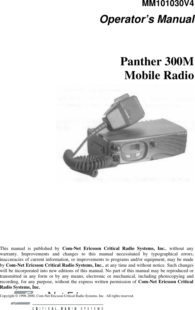
Operators Manual
7.
Pages Part 1 from Install
8.
Pages Part 2 from Install
Revised Manual
Navigation menu
Upload a User Manual
Namespaces
Wiki Guide
HTML
PDF
Info
Views
User Manual
Discussion / Help
Navigation
![3 SAFETY INFORMATION RADIO OPERATOR WARNING Do not transmit with this radio and antenna when persons are within the MPE Radius* of the antenna [see “Determining MPE Radius” in this section], unless such persons (such as the driver or radio operator) are isolated from the antenna field by a grounded metallic barrier (such as the user's vehicle rooftop). MPE Radius is the minimum distance from the antenna axis that persons should maintain in order to avoid RF exposure higher than the allowable MPE level set by the FCC for General Population/Uncontrolled Exposure, as specified in 47 CFR § 1.1310. FAILURE TO OBSERVE THESE LIMITS MAY ALLOW THOSE WITHIN THE MPE RADIUS* TO EXPERIENCE RF RADIATION ABSORPTION WHICH EXCEEDS THE FCC MAXIMUM PERMISSIBLE EXPOSURE (MPE) LIMIT FOR GENERAL POPULATION/UNCONTROLLED EXPOSURE. The shorter MPE Radius distances listed for the Occupational/ Controlled limits, as specified in 47 CFR § 1.1310, may be used if the user meets the following conditions: a) the user is exposed to the RF energy as a consequence of their employment, b) the user is aware of their exposure to the RF energy due to their training by reading this Operator’s manual, and c) the user exercises control over their exposure. In this case, the user knows they are using a Push-To-Talk land mobile radio whose transmitter is rated for a 20% intermittent duty cycle.](https://usermanual.wiki/HARRIS/TR-0005-A.Revised-Manual/User-Guide-114095-Page-5.png)