HARRIS TR-0005-A UHF-FM Land Mobile Transceiver User Manual P300M Operator sManualR4
HARRIS CORPORATION UHF-FM Land Mobile Transceiver P300M Operator sManualR4
HARRIS >
Contents
Revised Manual
MM101030V4
Operator’s Manual
Panther 300M
Mobile Radio
This manual is published by Com-Net Ericsson Critical Radio Systems, Inc.
, without any
warranty. Improvements and changes to this manual necess
itated by typographical errors,
inaccuracies of current information, or improvements to programs and/or equipment, may be made
by Com-Net Ericsson Critical Radio Systems, Inc.
, at any time and without notice. Such changes
will be incorporated into new edit
ions of this manual. No part of this manual may be reproduced or
transmitted in any form or by any means, electronic or mechanical, including photocopying and
recording, for any purpose, without the express written permission of Com-
Net Ericsson Critical
Radio Systems, Inc.
Copyright © 1998-2000, Com-Net Ericsson Critical Radio Systems, Inc. All rights reserved.

1
Table Of Contents
SAFETY INFORMATION................................................................ 3
RADIO OPERATOR WARNING .................................................. 3
MPE NOTES ............................................................................... 7
TRANSMITTER HAZARDS ......................................................... 7
SAFE DRIVING RECOMMENDATIONS...................................... 8
OPERATING RULES AND REGULATIONS................................... 9
OPERATING TIPS .................................................................... 11
INTRODUCTION .......................................................................... 12
CONTROLS, DISPLAYS AND INDICATORS ............................... 13
CONTROLS .............................................................................. 13
OPTION BUTTON FUNCTIONS................................................ 14
Disabled.............................................................................. 14
Monitor/Clear....................................................................... 14
Local/Distant Squelch.......................................................... 15
Type 99 On/Off.................................................................... 15
Home Channel .................................................................... 16
Horn Alert On/Off................................................................. 16
Public Address On/Off......................................................... 17
Internal/External Speaker .................................................... 17
HOOKSWITCH FUNCTIONS .................................................... 17
DISPLAY................................................................................... 19
PANTHER 300M Display..................................................... 19
Display Status And Error Codes .......................................... 19
Self Test Error Messages .................................................... 21
RADIO INDICATORS ................................................................ 22
Option Status Leds.............................................................. 22
Busy / Tx Indicator............................................................... 22
ALERT TONES ......................................................................... 24
Power Up ............................................................................ 24
Carrier Control Timer........................................................... 24
Denied Tone ....................................................................... 24
Failed Tone......................................................................... 24
Option Button Keypress That Disables................................. 24
Option Button Keypress That Enables ................................. 25
Transmitter Disabled ........................................................... 25
Type 99 Individual Call ........................................................ 25
Type 99 Group Call ............................................................. 25
Type 99 Super Group/Quick Call ......................................... 25
Synthesizer Unlock.............................................................. 25
BASIC OPERATION..................................................................... 26
TURNING THE RADIO ON........................................................ 26
SELECTING OR CHANGING CHANNELS ................................ 26
TRANSMITTING A BASIC CALL ............................................... 26
PUBLIC ADDRESS MESSAGE ................................................. 27
CHANNEL GUARD ................................................................... 28
Channel Guard Monitor Function......................................... 28
SENDING DTMF WITH THE DTMF MICROPHONE.................. 28

Com-Net Ericsson Critical Radio Systems, Inc. 2
P.O. Box 2000
Lynchburg, Virginia 24501 MM101030V3
1-800-528-7711 (Outside USA, 804-592-7711) Printed in U.S.A.
Table Of Contents (Continued)
SELECTIVE SIGNALING.............................................................. 29
TYPE 99 OPERATION .............................................................. 30
Receiving An Individual, Group, or Supergroup Call............. 30
Resetting Type 99 After A Call............................................. 31
PROGRAMMABLE PTT FUNCTIONS ....................................... 31
Channel Busy Lockout......................................................... 31
Channel Guard Channel Busy Lockout ................................ 31
Type 99 Disable After PTT................................................... 32
Ignition A+ Disable............................................................... 32
PROGRAMMABLE HORN ALERT FUNCTIONS........................ 33
External Alarms ................................................................... 33
Resetting the Car Horn Alert................................................ 33
Car Horn Alert Ignition A+ Option......................................... 33

3
SAFETY INFORMATION
RADIO OPERATOR WARNING
Do not transmit with this radio and antenna when
persons are within the MPE Radius* of the antenna
[see “Determining MPE Radius” in this section], unless
such persons (such as the driver or radio operator) are
isolated from the antenna field by a grounded metallic
barrier (such as the user's vehicle rooftop). MPE
Radius is the minimum distance from the antenna axis
that persons should maintain in order to avoid RF
exposure higher than the allowable MPE level set by
the FCC for General Population/Uncontrolled
Exposure, as specified in 47 CFR § 1.1310.
FAILURE TO OBSERVE THESE LIMITS MAY ALLOW THOSE
WITHIN THE MPE RADIUS* TO EXPERIENCE RF
RADIATION ABSORPTION WHICH EXCEEDS THE FCC
MAXIMUM PERMISSIBLE EXPOSURE (MPE) LIMIT FOR
GENERAL POPULATION/UNCONTROLLED EXPOSURE.
The shorter MPE Radius distances listed for the Occupational/
Controlled limits, as specified in 47 CFR § 1.1310, may be used if the
user meets the following conditions:
a) the user is exposed to the RF energy as a consequence of their
employment,
b) the user is aware of their exposure to the RF energy due to their
training by reading this Operator’s manual, and
c) the user exercises control over their exposure. In this case, the
user knows they are using a Push-To-Talk land mobile radio whose
transmitter is rated for a 20% intermittent duty cycle.

Com-Net Ericsson Critical Radio Systems, Inc. 4
P.O. Box 2000
Lynchburg, Virginia 24501 MM101030V2
1-800-528-7711 (Outside USA, 804-592-7711) Printed in U.S.A.
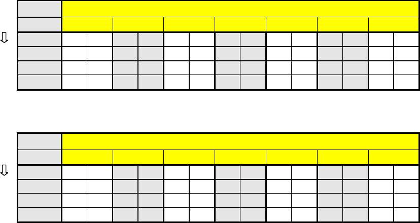
Determining MPE Radius*
In the tables following, MPE Radii are listed for ranges of power within
which this radio is intended to operate (20 - 40 Watts) and for antennas
having gains of 0 - 6 dBd (1/4 λλ, quarter-wave monopole = 0 dBd).
In order to determine the MPE Radius for your specific application,
choose the VHF or UHF table that meets either the FCC’s General
Population/Uncontrolled Exposure limits or the Occupational/
Controlled Exposure limits.
Then choose the row containing the appropriate power level into the
antenna and read the MPE Radius on that row under the appropriate
antenna gain. For powers or gains between listed numbers, choose the
next higher listed number in each case.
If you do not know the power level at which the radio is operating
(set by the personality program), assume the maximum of 40 Watts.
If you do not know the gain rating of the antenna, consult the
antenna provider. For antennas of higher gains than listed, consult
the supplier of this radio. If you do not know whether you are
qualified to use the shorter distances as defined by
Occupational/Controlled Exposure limits, then you must use the
longer distances specified by the General Population/Uncontrolled
Exposure limits.
5
**Example: 450 MHz Band, 40 Watts and 2.5 dBd gain >>> follow 40 Watt row to 3 dBd
column, which yields186 cm (73 in) as the MPE Radius.
MPE Radii for General Population/Uncontrolled Exposure: VHF Band (136 - 174 MHz1)
Power3 dBd Antenna Gain4
(Watts)
0 1 2 3 4 5 6
cm
in cm
in cm
in cm
in cm
in cm
in cm
in
20 115
45 128
50 144
57 161
64 181
71 203
80 228
90
30 140
55 157
62 176
69 198
78 222
87 248
98 279
110
40 162
64 181
71 203
80 228
90 256
101
287
113
322
127
MPE Radii for General Population/Uncontrolled Exposure: UHF Band (450 - 512 MHz2)
Power3 dBd Antenna Gain4
(Watts)
0 1 2 3 4 5 6
cm
in cm
in cm
in cm
in cm
in cm
in cm
in
20 93 37 105
41 117
46 132
52 148
58 166
65 186
73
30 114
45 128
50 144
57 161
64 181
71 203
80 228
90
40 132
52 148
58 166
65 186
73 209
82 234
92 263
104

Com-Net Ericsson Critical Radio Systems, Inc. 6
P.O. Box 2000
Lynchburg, Virginia 24501 MM101030V3
1-800-528-7711 (Outside USA, 804-592-7711) Printed in U.S.A.
**Example: 450 MHz Band, 40 Watts and 2.5 dBd gain >>> follow 40 Watt row to 3 dBd
column, which yields 83 cm (33 in) as the MPE Radius.
MPE Radii for Occupational/Controlled Exposure: VHF Band (136 - 174 MHz1)
Power3 dBd Antenna Gain4
(Watts)
0 1 2 3 4 5 6
cm
in cm
in cm
in cm
in cm
in cm
in cm
in
20 51 20 57 23 64 25 72 28 81 32 91 36 102
40
30 63 25 70 28 79 31 88 35 99 39 111
44 125
49
40 72 28 81 32 91 36 102
40 115
45 128
51 144
57
MPE Radii for Occupational/Controlled Exposure: UHF Band (450 - 512 MHz2)
Power3 dBd Antenna Gain4
(Watts)
0 1 2 3 4 5 6
cm
in cm
in cm
in cm
in cm
in cm
in cm
in
20 42 16 47 18 53 21 59 23 66 26 74 29 83 33
30 51 20 57 23 64 25 72 28 81 32 91 36 102
40
40 59 23 66 26 74 29 83 33 93 37 105
41 118
46
7
MPE NOTES
1. Numbers are calculated for any VHF frequency, since MPE radii is
the same.
2. Numbers are calculated for 450 MHz, giving the largest (worst-case)
MPE radii.
3. Power delivered to antenna: radio output less cable and mismatch
losses.
4. Gains are compared to an ideal, 1/4-wave monopole (1/2-wave
dipole). Add 2.15 dB for comparison with an ideal isotropic source.
(0 dBd = 2.15 dBi)
TRANSMITTER HAZARDS
The operator of any mobile radio should be aware of
certain hazards common to the operation of
vehicular radio transmitters. A list of several
possible hazards is given:
1. Explosive Atmospheres - Just as it is dangerous to fuel a vehicle
with the motor running, similar hazards exist when operating a
mobile radio. Be sure to turn the radio off while fueling a vehicle.
Do not carry containers of fuel in the trunk of a vehicle if the radio is
mounted in the trunk.
Areas with potentially explosive atmosphere are often, but not
always, clearly marked. Turn OFF your radio when in any area
with a potentially explosive atmosphere. It is rare, but not
impossible that the radio or its accessories could generate
sparks.
2. Interference to Vehicular Electronics Systems - Electronic fuel
injection systems, electronic anti-skid braking systems, electronic
cruise control systems, etc., are typical electronic systems that may
malfunction due to the lack of protection from radio frequency
energy present when transmitting. If the vehicle contains such
equipment, consult the dealer and enlist their aid in determining the
expected performance of electronic circuits when the radio is
transmitting.
Com-Net Ericsson Critical Radio Systems, Inc. 8
P.O. Box 2000
Lynchburg, Virginia 24501 MM101030V3
1-800-528-7711 (Outside USA, 804-592-7711) Printed in U.S.A.
3. Dynamite Blasting Caps - Dynamite blasting caps may be caused to
explode by operating a radio within 500 feet of the blasting caps.
Always obey the "Turn Off Two-Way Radios" signs posted where
dynamite is being used.
When transporting blasting caps in your vehicle:
a. Carry the blasting caps in a closed metal box with a soft lining.
b. Leave the radio OFF whenever the blasting caps are being put
into or removed from the vehicle.
4. Liquefied Petroleum (LP) Gas Powered Vehicles - Mobile radio
installations in vehicles powered by liquefied petroleum gas with the
LP gas container in the trunk or other sealed-off space within the
interior of the vehicle must conform to the National Fire Protection
Association standard (NFPA) 58 requiring:
a. The space containing the radio equipment shall be isolated by a
seal from the space containing the LP gas container and its
fittings.
b. Outside filling connections shall be used for the LP gas
container.
c. The LP gas container shall be vented to the outside of the
vehicle.
SAFE DRIVING RECOMMENDATIONS
(Recommended By AAA)
• Read the literature on the safe operation of the radio.
• Keep both hands on the steering wheel and the microphone in its
hanger whenever the vehicle is in motion.
• Place calls only when vehicle is stopped.
• When talking from a moving vehicle is unavoidable, drive in the
slower lane. Keep conversations brief.
• If a conversation requires taking notes or complex thought, stop the
vehicle in a safe place and continue the call.
• Whenever using a mobile radio, exercise caution.

9
OPERATING RULES AND REGULATIONS
Two-way FM radio systems must be operated in accordance with the
rules and regulations of the local, regional, or national government.
In the United States, the PANTHER 300M radio must be operated in
accordance with the rules and regulations of the Federal
Communications Commission (FCC). As an operator of two-way radio
equipment, you must be thoroughly familiar with the rules that apply to
your particular type of radio operation. Following these rules helps
eliminate confusion, assures the most efficient use of the existing radio
channels, and results in a smoothly functioning radio network. When
using your two-way radio, remember these rules:
1. It is a violation of FCC rules to interrupt any distress or emergency
message. As your radio operates in much the same way as a
telephone "party line", always listen to make sure that the channel
is clear before transmitting. Emergency calls have priority over all
other messages. If someone is sending an emergency message - such
as reporting a fire or asking for help in an accident - KEEP OFF
THE AIR!
2. The use of profane or obscene language is prohibited by Federal law.
3. It is against the law to send false call letters or false distress or
emergency messages. The FCC requires that you keep conversations
brief and confine them to business. To save time, use coded
messages whenever possible.
4. Using your radio to send personal messages (except in an
emergency) is a violation of FCC rules. You may send only those
messages that are essential for the operation of your business.
5. It is against Federal law to repeat or otherwise make known anything
you overhear on your radio. Conversations between others sharing
your channel must be regarded as confidential.
6. The FCC requires that you identify yourself at certain specific times
by means of your call letters. Refer to the rules that apply to your
particular type of operation for the proper procedure.
7. No changes or adjustments shall be made to the equipment except by
an authorized or certified electronic technician.

Com-Net Ericsson Critical Radio Systems, Inc. 10
P.O. Box 2000
Lynchburg, Virginia 24501 MM101030V3
1-800-528-7711 (Outside USA, 804-592-7711) Printed in U.S.A.
Under U.S. law, operation of an unlicensed radio transmitter within the
jurisdiction of the United States may be punishable by a fine of up to
$10,000, imprisonment for up to two years, or both.
IMPORTANT

11
OPERATING TIPS
The following conditions tend to reduce the effective range of two-way
radios and should be avoided whenever possible:
• Operating the radio in areas of low terrain, or while under power
lines or bridges.
• Obstructions such as mountains and buildings.
In areas where transmission or reception is poor, some improvement may
be obtained by insuring that the antenna is vertical. Moving a few yards
in another direction or moving to a higher elevation may also improve
communication.

Com-Net Ericsson Critical Radio Systems, Inc. 12
P.O. Box 2000
Lynchburg, Virginia 24501 MM101030V3
1-800-528-7711 (Outside USA, 804-592-7711) Printed in U.S.A.
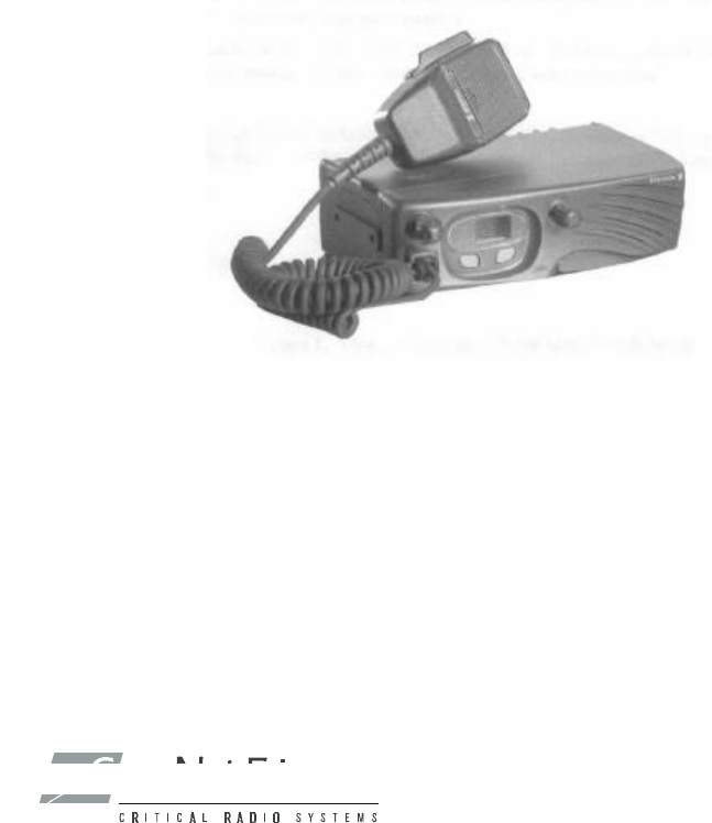
INTRODUCTION
This manual describes the operation for the Com-Net Ericsson Panther
300M Mobile radio. The Panther 300M radio is a high performance FM
mobile radio providing reliable two-way communication in a
Conventional radio system.
The Panther 300M radio can be programmed with up to 6 channels. The
Panther 300M radio includes a 7-segment, two character numeric display
for channel display.
The Panther 300M radio can be programmed to operate with any of the
following Conventional radio system platforms:
q Channel Guard (with or without STE)
q Digital Channel Guard
q Type 99
The Panther 300M is a versatile radio designed to meet most
Conventional applications. The 300M radio will be available in
numerous splits in the VHF and UHF bands. The 300M radio can be
purchased with a maximum output power of 40 Watts with a turndown to
20 Watts. For both the 20 Watt and the 40 Watt units, the radio can be
programmed for low or high power on a per channel basis. A Canadian
option is available in the Maintenance software to limit the maximum
power to 30 Watts. The following table provides a complete list of the
300M radios model numbers.
Table 1 – Panther 300M Radio Model Numbers
Radio Model # Description
KRD 103 154/1 136-155 MHz, 20-40 Watt
KRD 103 154/2 150-174 MHz, 20-40 Watt
KRD 103 154/3 450-488 MHz, 20-40 Watt
KRD 103 154/4 470-512 MHz, 20-40 Watt
13
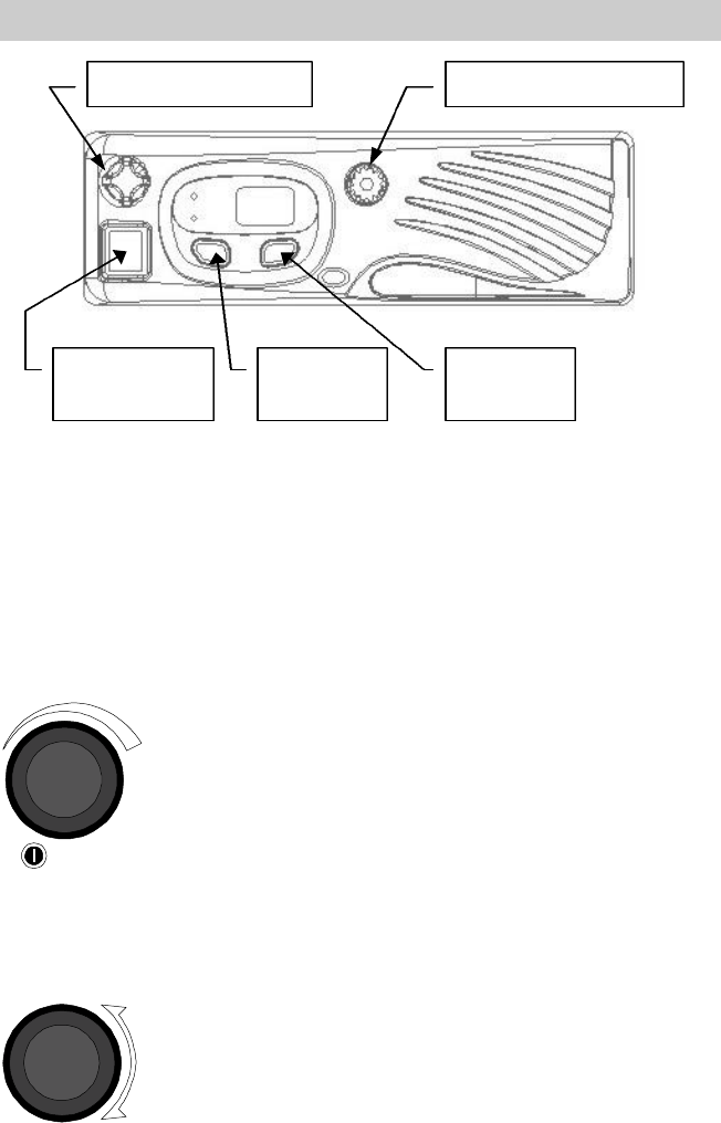
CONTROLS, DISPLAYS AND INDICATORS
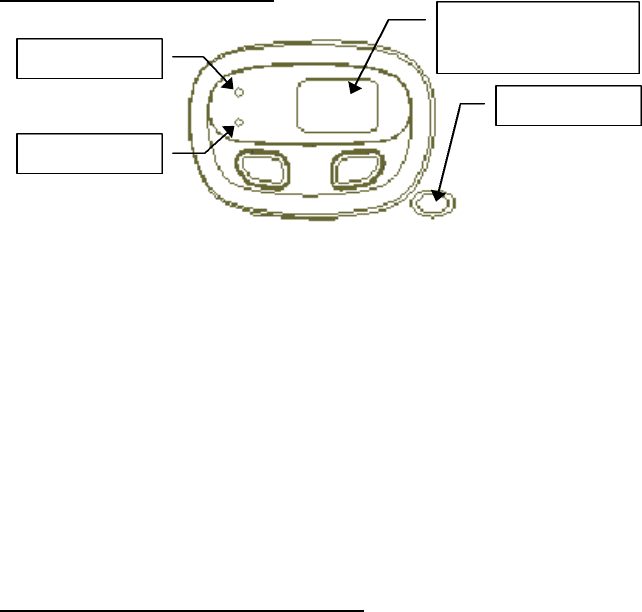
Figure 1 – Panther 300M Radio Front View
CONTROLS
All the controls for the Panther 300M mobile radio are located on the
front of the control unit and described below:
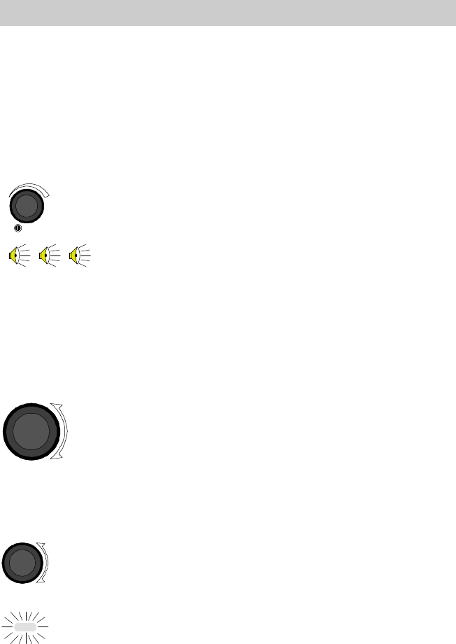
ON/OFF Volume Knob
This knob powers the radio ON/OFF and controls the
volume level of the received audio at the speaker. Rotate
the knob counterclockwise to turn the volume down.
Rotate the knob clockwise to turn the volume up. Rotate
the knob counterclockwise until it clicks and then stops,
to turn the radio OFF. When the knob is in the OFF
position, rotate the knob clockwise until the knob clicks
to turn the radio ON.
Channel Selector Knob
This 6 position rotary knob is used to select the desired
channel from a preprogrammed list of channels. Rotate
the knob clockwise to increment to the next channel in
the list. Rotate the knob counterclockwise to decrement
to the next channel in the list.
On/Off Volume Knob
Channel Selector Knob
Microphone
Connector
Option 1
Button
Option 2
Button

Com-Net Ericsson Critical Radio Systems, Inc. 14
P.O. Box 2000
Lynchburg, Virginia 24501 MM101030V3
1-800-528-7711 (Outside USA, 804-592-7711) Printed in U.S.A.
Option 1 Button
This button can be programmed to control one of the
radio's programmable option functions. The default
function is "Monitor/Clear".
Option 2 Button
This button can be programmed to control one of the
radio's option functions. The default function is
"Disabled".
OPTION BUTTON FUNCTIONS
The following functions can be assigned to one of the two option
buttons. The same function can not be assigned to both option buttons.
?
In order to prevent inadvertent operation, the Option Buttons
must be pressed for at least one second before they execute
their programmed function.
Disabled
No function is assigned to the option button. When pressed, the radio
will give the Denied alert tone. This is the default for Option Button 2.
Monitor/Clear
The Monitor/Clear function monitors the channel for activity. While
pressed, noise squelch is disabled, Channel Guard is disabled, Type 99 is
disabled, and the option button's LED is turned on.
If the channel is not busy, squelch noise will be heard. If the channel is
busy, the activity on the channel will be heard.
When the option button is released, the option button's LED will turn off,
Type 99 will be re-enabled, Channel Guard will be re-enabled, and noise
squelch will be re-enabled.
Pressing the Monitor/Clear option button can also be used to clear the
Type 99 Decoder state from Monitor Mode to Selective Signaling mode

15
after a successful Type 99 decode and to reset the Horn Alert function
after a Type 99 Individual Call.
This is the default function for the Panther 300M's Option 1 button.
Local/Distant Squelch
The Local/Distant Squelch function overrides the channel's programmed
local/distant squelch setting. This is a toggle function. If the radio is
currently using the tighter Local squelch, then pressing the Local/Distant
Squelch button will change the squelch setting to the looser Distant
setting. If the radio is currently using the Distant settings, then pressing
the option Local/Distant button will change the squelch settings to the
Local settings.
The option button's LED will be on when the radio is using its Local
squelch settings. The option button's LED is off when the radio is using
its Distant squelch settings.
There will be one keypress beep when going from Distant to Local and
two keypress beeps when going from Local to Distant.
Type 99 On/Off
The Type 99 On/Off function controls the state of the Type 99 Decoder.
When "On", the option button's LED is on and the radio is put into
Selective mode. The Type 99 function will mute receive audio until it
receives a valid Type 99 call.
When "Off", the radio is always in Monitor mode. The option button's
LED will be off.
The Type 99 On/Off function is a toggle function. There will be one
keypress beep when the function goes from "Off" to "On" and two
keypress beeps when the function goes from "On" to "Off".
The Type 99 On/Off function requires a Type 99 decode be programmed
on the displayed channel. If this is not the case, the Type 99 On/Off
function will just do a Denied Alert Tone.
When the channel is changed or when the radio is powered up, the Type
99 decoder will change to the programmed Selective Call or Monitor
Mode default state.

Com-Net Ericsson Critical Radio Systems, Inc. 16
P.O. Box 2000
Lynchburg, Virginia 24501 MM101030V3
1-800-528-7711 (Outside USA, 804-592-7711) Printed in U.S.A.
Home Channel
The Home Channel function will set the radio channel from the
frequency switch selection to the preprogrammed Home Channel. When
"On", the preprogrammed Home Channel number will be in the display
and the option button's LED will be on. When the function is "Off", then
the frequency switch selection channel will be in the display and the
option button's LED will be off.
The Home Channel function is a toggle function. There will be one
keypress beep when the function goes from "Off" to "On" and two
keypress beeps when the function goes from "On" to "Off".
The radio will have all the programmed features of the home channel
number when the Home Channel function is selected.
Changing the channel selection knob or turning the radio off and then
back on will cancel the Home Channel Function.
Horn Alert On/Off
The Horn Alert On/Off function controls operation of the Horn Alert
function of the Type 99 decoder. When "On", the Horn Alert function is
enabled. The option button's LED is on. Reception of a Type 99
Individual Call will activate the horn alert relay.
When "Off", the Horn Alert function is disabled. The option button's
LED is off. Reception of a Type 99 Individual Call will not activate the
horn alert relay.
The Horn Alert On/Off function is a toggle function. There will be one
keypress beep when the function goes from "Off" to "On" and two
keypress beeps when the function goes from "On" to "Off".
The Horn Alert On/Off function requires a Type 99 Individual Call be
programmed on the displayed channel. If this is not the case, attempting
to enable the Horn Alert On/Off function will just produce the Denied
Alert tone.
If Type 99 is not enabled when the Horn Alert On/Off function is
enabled, then the radio will enable the Type 99 decoder. However,
disabling the Horn Alert On/Off function will not disable the Type 99
decoder function.

17
Changing the channel selection knob or turning the radio off and then
back on will cancel the Home Channel Function.
Public Address On/Off
The Public Address function controls Public Address operation. When
"On", the Public Address function is active. The option button's LED is
on. Pressing PTT will send microphone audio through the radio's
receive amplifier to the external speaker.
When "Off", the public address function is not active. The option
button's LED will be off. Pressing PTT will key the transmitter and send
microphone audio through the transmitter.
The Public Address On/Off function is a toggle function. There will be
one keypress beep when the function goes from "Off" to "On" and two
keypress beeps when the function goes from "On" to "Off".
Internal/External Speaker
The Internal/External Speaker function allows receive audio to go to an
internal or external speaker. When "External Speaker" is selected, the
speaker relay is activated, receive audio goes to the external speaker, and
the option button's LED is on. When "Internal Speaker" is selected, the
speaker relay is not activated, receive audio goes to the internal speaker,
and the option button's LED is off.
When going from internal to external speaker, there will be one Keypress
Alert Tone. When going from external to internal speaker, there will be
two Keypress Alert Tones.
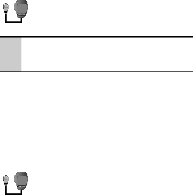
HOOKSWITCH FUNCTIONS
The microphone hookswitch functions can be enabled or disabled in the
radio personality. The sense of the hookswitch is also a radio personality
entry.
When enabled, removing the microphone from its bracket will disable
the Channel Guard and Type 99 decoders to allow monitoring of the
channel. Note taking the microphone off-hook does not disable noise
squelch. As a result, unlike pressing the Monitor/Clear button, the radio
seems quiet when there is no activity.
Returning the microphone to the bracket will re-enable any programmed
Channel Guard or Type 99 decoder.
Com-Net Ericsson Critical Radio Systems, Inc. 18
P.O. Box 2000
Lynchburg, Virginia 24501 MM101030V3
1-800-528-7711 (Outside USA, 804-592-7711) Printed in U.S.A.
Returning on-hook will also reset the Type 99 decoder from Monitor
Mode to Selective Call Mode after a valid Type 99 decode.
Lastly, if the Horn Alert function has been activated, returning the
microphone to the hookswitch will deactivate and reset the Horn Alert
function for the next in Type 99 individual call.
19
DISPLAY
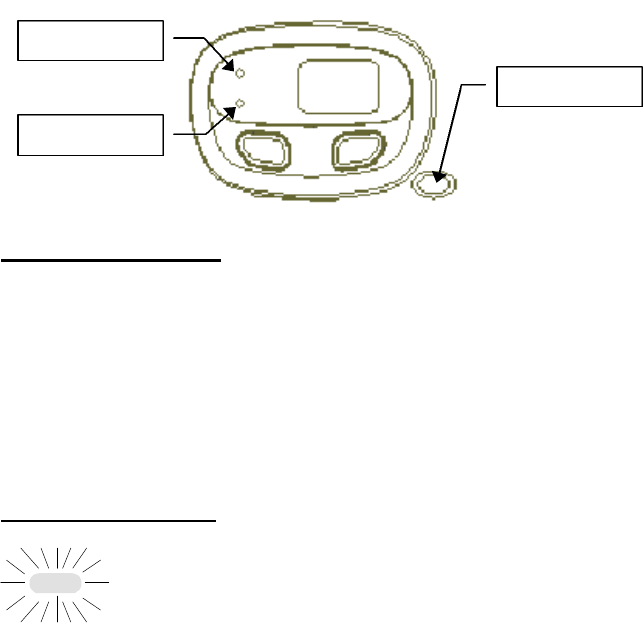
PANTHER 300M Display
Figure 2 - PANTHER 300M Display
The PANTHER 300M includes a dual two character 7-segment display,
two LEDs to indicate Option Function Status, and a tri-color LED to
indicate Transmit/Receive Status. The 7 Segment Displays are also used
to provide various radio status information and error status information.
The PANTHER 300M radio normally displays the
selected channel by displaying the selected channel
number in the two 7 Segment Displays. The
PANTHER 300M radio can not display the channel
name defined in the radio personality, only the
channel number.
Display Status And Error Codes
Mobile is in CopyCat Mode number.
Carrier Control Timer Timeout. The transmitter has
been disabled by the Carrier Control Timer function.
"CC" will be displayed and the carrier Control Alert
Tone will be sounded until PTT is released.
Empty Channel. The channel selector switch is either
on an invalid channel position or the current channel
position is not programmed. Verify the channel
selector switch is in its proper detent and that the
channel is properly programmed.
Busy/Tx LED
Dual 7 Segment
Displays
Option 1 LED
Option 2 LED
1 … 6
C
CC
EC
Com-Net Ericsson Critical Radio Systems, Inc. 20
P.O. Box 2000
Lynchburg, Virginia 24501 MM101030V3
1-800-528-7711 (Outside USA, 804-592-7711) Printed in U.S.A.
Locked Channel. The transmission is not allowed
due to the channel busy lockout option and a busy
channel condition..
No Ignition A+. The transmission is not allowed due
to the Ignition A+ option and the lack of DC power at
the Option Connector's Ignition A+ pin.
The radio is currently in programming mode. If this
inadvertently occurs during normal operation, turn
the radio power off and then on.
Public Address. The Public Address option is
enabled and is currently active. Microphone Audio
will be routed through the receiver audio PA to the
external speaker.
Power Down. The transmitter is disabled due to the
software thermal protection function.
Power Error. The radio has sensed either excessive
or no RF power when the radio should be
transmitting. There is either an antenna failure or a
radio PA failure present.
Synthesizer Unlocked. The synthesizer is unlocked
during normal operating conditions. This is an error
condition where the radio is not on receive or
transmit on the desired frequency. The error
condition could be due to an inappropriate
personality or a hardware failure in the radio's RF
frequency generation circuitry. The radio should
returned for service to a qualified radio technician.
LC
nA
P
Pd
PE
PA
UL

21
Self Test Error Messages
Personality Checksum Error. Reprogram the radio
with a valid personality. If the error persists, the
radio should be returned for service to a qualified
radio technician.
Tracking Data Error. The radio should be returned
for service to a qualified radio technician.
Inapprorpiate RD Power. RF power is being sensed
when the radio should not be transmitting. The radio
should be returned for service to a qualified radio
technician.
Synthesizer Unlocked At Power-Up. The radio could
not lock upon the receive channel frequency during
power-up. Reprogram the radio with a valid
personality. If the error persists, the radio should be
returned for service to a qualified radio technician.
CopyCat Error. The radio cloning operation failed.
If the error persists, the radio should be returned for
service to a qualified radio technician.
Flash Software Checksum Error. The radio's
operating software has been corrupted. The radio
should be returned for service to a qualified radio
technician.
E1
E2
E3
E4
E5
E6
Com-Net Ericsson Critical Radio Systems, Inc. 22
P.O. Box 2000
Lynchburg, Virginia 24501 MM101030V3
1-800-528-7711 (Outside USA, 804-592-7711) Printed in U.S.A.
RADIO INDICATORS
Option Status Leds
The two Option Status LEDs to the left of the seven segment displays
indicate the current state of the option that is programmed into the
corresponding Option key. The upper LED indicates the state of option
assigned to the Option 1 button. The lower LED indicates the state of
the option assigned to the Option 2 button.
When the option is "Enabled", or "on" the LED will be on. When the
option is "disabled" or "off", then the LED will be off.
Busy / Tx Indicator
This indicator is to the right of the option buttons toward
the bottom of the radio. It is a three color LED. The
LED can be Red, Green, or Orange. The LED can also
be on steady or flashing depending upon the radio state.
The LED is most frequently used to indicate when the
radio is transmitting and when the channel is busy.
When the radio is transmitting, the red LED turns on
steady. When the radio channel is in use or "busy", the
green LED turns on steady.
Note that the steady green LED does not necessarily
indicate a received call if the channel has Channel Guard
or Type 99 signaling. The steady green LED only
means that the channel is in use.
Busy/Tx LED
Option 1 LED
Option 2 LED
23
A flashing green light means the radio is on a Type 99
channel that has decoded a Type 99 call. If it is flashing
more off than on (950 milliseconds off, 50 milliseconds
on) then there is no carrier present on the displayed
channel. If the green LED is flashing more on than off
(950 milliseconds on, 50 milliseconds off), then there is
a carrier present on the displayed channel.
An orange LED usually indicates an error condition or
radio failure.
Com-Net Ericsson Critical Radio Systems, Inc. 24
P.O. Box 2000
Lynchburg, Virginia 24501 MM101030V3
1-800-528-7711 (Outside USA, 804-592-7711) Printed in U.S.A.
ALERT TONES
The PANTHER 300M radio generates a number of unique audible alert
tones or “beeps” to indicate various operating conditions. The alert tone
feature can be enabled or disabled through PC Programming. All of the
PANTHER 300M alert tones are described in the following sections:
Power Up
On power up, the radio performs a diagnostic test and
then sounds three short tones to indicate the radio has
passed the diagnostic test and is ready for operation.
Carrier Control Timer
The Carrier Control Timer (CCT) is a programmable
timer that limits the amount of time the radio will allow
the user to continuously transmit. Once the time period
has expired, the radio ends the transmission and sounds
a warning tone. The warning tone will continue until the
user releases the PTT button on the microphone.
Denied Tone
A short beep that sounds when an action produces an
error or has no meaning. For example, pressing the
Type 99 On/Off option button when the displayed
channel does not have a Type 99 call defined.
Failed Tone
The Failed tone is a continuous low frequency tone that
is sounded when the radio fails its power-up self test or
when another fatal error occurs. The tone will sound
indefinitely until the radio is turned off.
Option Button Keypress That Disables
An option keypress that disables a function will sound
two short beeps.
…
…
25
Option Button Keypress That Enables
An option keypress that enables a function will sound
one short beep.
Transmitter Disabled
The Transmitter Disable Tone will sound when the PTT
is pressed but transmit operation is locked out by the
Busy Lockout Options. The warning tone will continue
until the user releases the PTT button on the
microphone. This tone will also sound when the PTT is
pressed on a receive only channel.
Type 99 Individual Call
When the radio receives an individual call, the radio will
sound one (1) short beep to alert the user of an
individual call.
Type 99 Group Call
When the radio receives a group call, the radio will
sound two (2) short beeps to indicate the radio has
received a group call.
Type 99 Super Group/Quick Call
When the radio receives a CNE super group or a
Motorola Quick Call, the radio will sound three (3) short
beeps to indicate the radio has received a super group or
Quick Call.
Synthesizer Unlock
If the synthesizer is unable to load and lock on the
channel, an alert tone will sound until the synthesizer
locks on the channel.
…
…
Com-Net Ericsson Critical Radio Systems, Inc. 26
P.O. Box 2000
Lynchburg, Virginia 24501 MM101030V3
1-800-528-7711 (Outside USA, 804-592-7711) Printed in U.S.A.
BASIC OPERATION
TURNING THE RADIO ON
Typically, mobile radio installations require the vehicle ignition switch
to be in the Accessory or Run position before the radio will power ON.
In some applications, the radio is wired directly to the battery and the
radio will power ON regardless of the setting of the vehicle ignition.
Verify with the installer how the radio has been connected.
From the OFF position, rotate the ON/OFF Volume
knob clockwise until the knob clicks. The radio
performs a diagnostic test and then sounds three short
tones to indicate the radio has passed the diagnostic test
and is ready for operation. The display comes ON and
indicates the currently selected channel.
SELECTING OR CHANGING CHANNELS
Rotate the Channel Selector Knob clockwise or
counterclockwise until the desired channel appears in
the display.
The Channel Knob is a rotary knob that is used to select
the desired channel. Rotate the knob clockwise to
increment to the next channel. Rotate the knob
counterclockwise to decrement to the previous channel.
TRANSMITTING A BASIC CALL
1. Make sure the radio is ON. Select the desired
system and channel as described in the previous
sections.
2. Observe the TX/RX indicator for any activity on the
channel..
3. Press and hold the Monitor/Clear button for at
least l second to monitor the channel for activity.
Noise will be heard if there is no activity on the
1 … 6
27
channel. This will also help in setting the volume
level to the desired level.
4. Remove the microphone from the hookswitch.
Holding the microphone approximately 2 inches from
your mouth, press the PTT button on the side of the
microphone and speak in the microphone.
?
Always speak in a normal tone of voice. Hold the microphone
cupped in your hand and approximately two (2) inches from
your mouth. Shouting will degrade your transmission, so do
not speak any louder than normal.
5. When you have finished speaking, release the PTT
button and wait for a reply.
PUBLIC ADDRESS MESSAGE
1. Verify the LED for the Public Address Option
Button is on. If it is not, press the Public Address
Option Button until it is.
2. Set the radio volume control to the desired public
address volume level. (Usually maximum volume.)
3. Remove the microphone from the hookswitch.
Holding the microphone approximately 2 inches
from your mouth, press the PTT button on the side
of the microphone and speak in the microphone.
4. When finished, replace the microphone on its
hookswitch.
5. Reset the volume control for a comfortable level.
6. Press the Public Address Option Button until its
LED turns off. The PTT and microphone audio will
now be directed to the radio transmitter.

Com-Net Ericsson Critical Radio Systems, Inc. 28
P.O. Box 2000
Lynchburg, Virginia 24501 MM101030V3
1-800-528-7711 (Outside USA, 804-592-7711) Printed in U.S.A.
CHANNEL GUARD
Channel Guard is a method of reducing "channel chatter" by equipping
receivers with a device which only allows calls with the correct signaling
to be heard by the user. Channel Guard is defined in the radio
personality.
The radio will always transmit with Channel Guard unless the channel is
programmed without Channel Guard.
Channel Guard Monitor Function
1) Observe the TX/RX indicator for any activity on the
channel.
2) Press the Monitor/Clear option button for at least 1
second.
3) If programmed, remove the microphone from its
hookswitch bracket.
SENDING DTMF WITH THE DTMF MICROPHONE
The optional DTMF microphone allows the radio to send DTMF
signaling. DTMF may be used in a radio system to access a telephone
line or to perform system control functions.
1. Select the desired system and channel as described
in the Basic Operation section on page 26. DTMF
must be enabled on the channel.
2. Observe the TX/RX indicator for any activity on the
channel.
3. Press the Monitor/Clear button to be sure there is
no activity on the channel. Typically, if there is
noise, there is no channel activity.
4. Remove the microphone from the hookswitch.
5. "Dial" the required DTMF digits from the telephone
keypad on the microphone. Do not hold the PTT

29
switch on the microphone down while dialing. The
DTMF microphone will automatically key the
transmitter.
SELECTIVE SIGNALING
Selective signaling is a method in conventional radio systems for
controlling the muting and unmuting of the receive audio. This allows
the radio operator or dispatcher to selectively call an individual radio or
group of radios. The PANTHER 300M radio supports selective
signaling in Type 99.
q In a selective signaling environment, the PANTHER 300M radio
operates in one of two states, Monitor mode or Selective Call mode.
In the monitor mode, the decoder's muting of the receive audio amp
is turned OFF and the user hears all calls on the channel.
In the selective mode, the encoder and decoder is turned ON and
only calls intended for the user will be heard.
q Selective signaling operates with or without Channel Guard.
q If Channel Guard is enabled, the radio can be programmed with an
"And" or an "Or" option. If the "And" option is programmed, the
user will only hear calls with the correct selective signaling and
correct Channel Guard.
If the "Or" option is programmed, the user will hear calls with the
correct selective signaling as well as calls with the correct Channel
Guard. Calls with the correct Channel Guard do not have to have the
correct selective signaling to be heard.
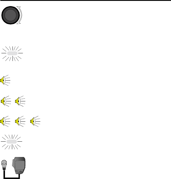
q When the radio is in the selective mode and the radio receives a
selective call, the radio switches to the monitor mode and the
Tx/Busy LED flashes green. The Tx/Busy LED always flashes
green when the radio is in the monitor mode. The Tx/Busy LED is
also used to indicate a carrier on the channel. This combination is
shown below.
Monitor mode Without Carrier On
Off
Monitor mode With Carrier On
Off
Com-Net Ericsson Critical Radio Systems, Inc. 30
P.O. Box 2000
Lynchburg, Virginia 24501 MM101030V3
1-800-528-7711 (Outside USA, 804-592-7711) Printed in U.S.A.
TYPE 99 OPERATION
Type 99 is Com-Net Ericsson’s proprietary method for in-band, two-tone
sequential signaling. It is a conventional signaling protocol used to
control the muting and unmuting of a radio. This signaling is commonly
used for selective calling of individual units or groups of units in a
conventional system. Type 99 is typically used in paging operations,
where a dispatcher is able to select which radio or radios are to be
selectively called.
If Type 99 has been setup, the radio can decode individual, group and
supergroup paging calls. When the radio decodes an appropriate Type
99 decode sequence, an alert sounds, the Tx/Busy LED flashes green and
the radio enters the monitor mode.
Receiving An Individual, Group, or Supergroup Call
1. Select the proper system and channel as described in
the Basic Operation on page 26.
2. When the radio receives a selective call:
Ø The green TX/RX indicator will turn ON to
indicate the radio is receiving a carrier.
Ø For an individual call, a single ½ second tone
will sound to indicate the call is an individual
call.
For a group call, two short tones will sound to
indicate the call is a group call.
For a supergroup call, three short tones will
sound to indicate the call is a supergroup call.
Ø The radio switches to the monitor mode and the
Tx/Busy LED flashes green.
3. To respond to the call, remove the microphone from
the hookswitch. Hold the microphone
approximately 2 inches from your mouth, press the

31
PTT button on the side of the microphone and speak
in the microphone.
Resetting Type 99 After A Call
When a Type 99 call is decoded, the radio enters Monitor mode. The
Type 99 decoder will now operate in the background. If the radio is
called again, the Type 99 decoder will decode it and sound the call's alert
tone. But the decoder will no longer mute the audio. All traffic on the
channel will now be heard. (If the channel has Channel Guard, only the
traffic with the radio's Channel Guard tone will be heard.)
In order for the Type 99 decoder to mute the audio, it must be "Reset".
There are several methods of doing this.
1. Press the Monitor/Clear button.
2. Place the microphone on its hookswitch. (If the
hookswitch function is enabled.)
3. Press the Type 99 On/Off button.
4. Allow an optional "Auto-Reset" timer to reset the
Type 99 decoder. This is a programmable option.
The time is also programmable between twelve
seconds and three minutes.
PROGRAMMABLE PTT FUNCTIONS
Channel Busy Lockout
The radio may be programmed to deny the use of the transmitter when
the channel is busy. This keeps another radio from interrupting a
message that is in progress. This is called Channel Busy Lockout.
If the PTT switch is pressed while the Busy/Tx LED is on, the radio will
display "LC" for "Locked Channel" and sound an alert tone until the
PTT is released.
Channel Guard Channel Busy Lockout
The radio may be programmed to deny the use of the transmitter when
the channel is busy with another Channel Guard tone. The radio will
transmit when the channel is busy with the radio's Channel Guard tone.
This is called Channel Guard Channel Busy Lockout.

Com-Net Ericsson Critical Radio Systems, Inc. 32
P.O. Box 2000
Lynchburg, Virginia 24501 MM101030V3
1-800-528-7711 (Outside USA, 804-592-7711) Printed in U.S.A.
If the PTT switch is pressed while the Busy/Tx LED is on and the radio
is muted because of an incorrect Channel Guard tone, the radio will
display "LC" for "Locked Channel" and sound an alert tone until the
PTT is released.
This option minimizes interference on repeater systems but also allows a
radio to transmit during the repeater dropout timer.
Type 99 Disable After PTT
The radio can be programmed to automatically disable the Type 99
decoder after a transmission. This is to allow for a reply to the
transmission.
The Type 99 decoder may then be reset by pressing the Monitor/Clear
button, putting the microphone back on its hookswitch, or may be
programmed for an Auto-Reset time.
Ignition A+ Disable
The radio can be programmed to deny the use of the transmitter if there
is no voltage on the Ignition A+ line. If the PTT is pressed when there is
no Ignition A+, then the radio will display "nA" for "Locked Channel"
and sound an alert tone until the PTT is released.
The Ignition A+ is usually connected to the vehicle's ignition switch.
The intent of the option is to allow the use of the transmitter only when
the vehicle engine is running. This is meant to prevent the transmitter
from draining the vehicle battery. It also has an effect of preventing
unauthorized use of the transmitter.

33
PROGRAMMABLE HORN ALERT FUNCTIONS
External Alarms
The car horn alert option can be programmed to give one of three alarms.
These are
1. A single 1 second alarm.
2. Three half second alarm pulses
3. Continuous alarm.
The first two are best suited for a horn function. The third option is
better suited for a light.
Resetting the Car Horn Alert
There are two ways of resetting the Car Horn Alert function. The default
is to reset the Car Horn Alert function when the Type 99 decoder is reset.
When this option is selected, a Type 99 Individual Call will activate the
alarm. However, subsequent Type 99 Individual Calls while the radio is
in Monitor Mode will not activate the alarm.
The second option is to automatically reset the Car Horn Alarm. When
this is selected, every Type 99 Individual Call will activate the alarm.
Even Type 99 Individual Calls while the radio is in Monitor Mode will
activate the alarm.
Car Horn Alert Ignition A+ Option
The radio can be programmed to ignore the Car Horn Alert function
when Ignition A+ is present. Ignition A+ is usually connected to the
vehicle's ignition switch and is used to indicate when the vehicle's engine
is running.
The usual purpose of the Car Horn Alert option is to provide a
notification to somebody outside the vehicle that they have an important
call. When the person is inside the vehicle and able to hear the Type 99
alert tones, the horn alert feature becomes undesirable. This option
provides an automatic means of disabling it while keeping it active for
when the person is out of the vehicle.