HARRIS TR-0005-A UHF-FM Land Mobile Transceiver User Manual M RK Standard and Enhanced Vehicular Charger
HARRIS CORPORATION UHF-FM Land Mobile Transceiver M RK Standard and Enhanced Vehicular Charger
HARRIS >
Contents
Install Manual Part 1
MM101031V1 R1A
Installation Manual
PANTHERTM 300M
Mobile Radio

2
Copyright © 2000, Com-Net Ericsson Critical Radio Systems, Inc. All rights reserved.
This manual is published by Com-Net Ericsson Critical Radio Systems, Inc., without any
warranty. Improvements and changes to this manual necessitated by typographical errors,
inaccuracies of current information, or improvements to programs and/or equipment, may be
made by Com-Net Ericsson Critical Radio Systems, Inc., at any time and without notice.
Such changes will be incorporated into new editions of this manual. No part of this manual
may be reproduced or transmitted in any form or by any means, electronic or mechanical,
including photocopying and recording, for any purpose, without the express written permission
of Com-Net Ericsson Critical Radio Systems, Inc.
The software contained in this device is copyrighted by Com-Net Ericsson
Critical Radio Systems, Inc. Unpublished rights are reserved under the
copyright laws of the United States.
NOTICE!
Repairs made to this equipment should be made only by an authorized
service technician or facility designated by the supplier. Any repairs,
alterations, or substitution of recommended parts made by the user to this
equipment not approved by the manufacturer could void the user’s
authority to operate the equipment in addition to the manufacturer’s
warranty.
NOTICE!

3
SAFETY INFORMATION .....................................................................................4
MAXIMUM PERMISSIBLE EXPOSURE (MPE) LIMITS................................5
DETERMINING MPE RADIUS .......................................................................5
SAFETY TRAINING INFORMATION ................................................................6
INTRODUCTION....................................................................................................8
UNPACK AND CHECK THE EQUIPMENT.......................................................8
OPTIONS AND ACCESSORIES......................................................................9
INSTALLATION ...................................................................................................10
STEP 1 - PLAN THE INSTALLATION .........................................................10
STEP 2 - LOCATE THE TOOLS REQUIRED...............................................10
STEP 3 – EQUIPMENT PREPARATION ......................................................11
Mounting..................................................................................................11
STEP 4 – PROGRAM THE RADIO................................................................16
STEP 5 – INSTALL CABLES.........................................................................17
Power Cable .............................................................................................17
Connect To Ignition Sense .......................................................................18
Radio Mounting Procedures.....................................................................20
STEP 7 – INSTALL OPTIONS AND ACCESSORIES ..................................22
Radio Option Cable..................................................................................22
External Speaker – 19A149590P11..........................................................25
Alarm (Horn) Relay Kit - 19A705499P1 .................................................28
Microphone Hanger/Hook Switch Mounting – 344A4678P1...................30
Antenna ....................................................................................................30
Noise Suppression Kit - Option KMPD1A (19A148539G1)....................32
FIGURES
Figure 1 – Typical Connection Diagram..................................................................12
Figure 2 – Removing Top Cover..............................................................................13
Figure 3 – Factory Default Internal Speaker Jumper Setting (Enabled)...................14
Figure 4 – Factory Default Settings For Jumper JP600............................................15
Figure 5 – Removing Plastic Cover..........................................................................16
Figure 6 – Power Cable RPM 113 7674/10..............................................................18
Figure 7 – Mounting Bracket and Mounting Bracket Hardware Kit ........................20
Figure 8 –Mounting Bracket Installation..................................................................21
Figure 9 – Mounting Radio to Bracket.....................................................................22
Figure 10 - Mounting the External Speaker .............................................................25
Figure 11 – External Speaker Option .......................................................................26
Figure 12 – Internal/External Speaker Relay............................................................27
Figure 13 - External Car Alert..................................................................................29
Figure 14 - External Alarm Relay ............................................................................29
Figure 15 – Ignition Sense Option............................................................................30
TABLES
Table 1 - PANTHER 300M Mobile Radio Options and Accessories ............................9
Table 2 – Radio Option Connector P3 Interface Description ...................................23
TABLE OF CONTENTS
4
SAFETY INFORMATION
The operator of any mobile radio should be aware of certain hazards
common to the operation of vehicular radio transmissions. A list of
several possible hazards is given:
1. Explosive Atmospheres - Just as it is dangerous to fuel a vehicle with
the motor running, similar hazards exist when operating a mobile radio,
be sure to turn the radio off while fueling the vehicle. Do not carry
containers of fuel in the trunk of the vehicle if the radio is mounted in
the trunk.
2. Interference to Vehicular Electronics Systems - Electronic fuel
injection systems, electronic anti-skid braking systems, electronic
cruise control systems, etc., are typical electronic systems that may
malfunction due to the lack of protection from radio frequency energy
present when transmitting. If the vehicle contains such equipment,
consult the dealer and enlist their aid in determining the expected
performance of electronic circuits when the radio is transmitting.
3. Dynamite Blasting Caps - Dynamite blasting caps may be caused to
explode by operating a radio within 500 feet of the blasting caps.
Always obey the "Turn Off Two-Way Radios" signs posted where
dynamite is being used.
When transporting blasting caps in your vehicle:
a. Carry the blasting caps in a closed metal box with a soft lining.
b. Leave the radio OFF whenever the blasting caps are being put into
or removed from the vehicle.
4. Liquefied Petroleum (LP) Gas Powered Vehicles - Mobile radio
installations in vehicles powered by liquefied petroleum gas with the
LP gas container in the trunk or other sealed-off space within the
interior of the vehicle must conform to the National Fire Protection
Association standard (NFPA) 58 requiring:
a. The space containing the radio equipment shall be isolated by a
seal from the space containing the LP gas container and its fittings.
b. Outside filling connections shall be used for the LP gas container.
c. The LP gas container shall be vented to the outside of the vehicle.

5
MAXIMUM PERMISSIBLE EXPOSURE (MPE)
LIMITS
Do not transmit with this radio and antenna when persons are within the
MPE Radius of the antenna, unless such persons (such as the driver or radio
operator) are shielded from the antenna field by a grounded metallic barrier
(such as the user’s vehicle rooftop). The MPE Radius is the minimum
distance from the antenna axis that persons should maintain in order to
avoid RF exposure higher than the allowable MPE level set by the FCC.
WARNING
FAILURE TO OBSERVE THESE LIMITS
MAY ALLOW THOSE WITHIN THE MPE
RADIUS TO EXPERIENCE RF RADIATION
ABSORPTION WHICH EXCEEDS THE FCC
MAXIMUM PERMISSIBLE EXPOSURE
(MPE) LIMIT. IT IS THE RESPONSIBILITY
OF THE RADIO OPERATOR TO ENSURE
THAT THE MAXIMUM PERMISSIBLE
EXPOSURE LIMITS ARE OBSERVED AT ALL TIMES
DURING RADIO TRANSMISSION. THE RADIO
OPERATOR IS TO ENSURE THAT NO BYSTANDERS
COME WITHIN THE RADIUS OF THE MAXIMUM
PERMISSIBLE EXPOSURE LIMITS SHOWN BELOW.
DETERMINING MPE RADIUS
THE MAXIMUM PERMISSIBLE EXPOSURE RADIUS HAS
BEEN ESTIMATED TO BE A RADIUS OF ABOUT 55
INCHES (OR 138 CM) FOR THE VEHICULAR MOUNTED
ANTENNA SYSTEMS, AND 77 INCHES (OR 195 CM) FOR
BASE STATION MOUNTED ANTENNA SYSTEMS PER OET
BULLETIN 65 OF THE FCC. THIS ESTIMATE IS MADE
ASSUMING THE MAXIMUM CAPABLE POWER OF THE
RADIOIS TRANSMITTED AND ANTENNAS WITH A
MAXIMUM GAINS OF 3 dBd ARE USED FOR VEHICULAR
MOUNTED SYSTEMS AND 6 dBd FOR BASE STATION
SYSTEMS.
A MAXIMUM 50% TRANSMIT DUTY CYCLE IS ASSUMED,
DUE TO THE PUSH-TO-TALK STATUS FO THIS MOBILE.

6
SAFETY TRAINING INFORMATION
WARNING
YOUR COM-NET ERICSSON PANTHER 300M
MOBILE RADIO GENERATES RF
ELECTROMAGNETIC ENERGY DURING
TRANSMIT MODE. THIS RADIO IS
DESIGNED FOR AND CLASSIFIED AS
“OCCUPATIONAL USE ONLY” MEANING
IT MUST BE USED ONLY IN THE COURSE OF
EMPLOYMENT BY INDIVIDUALS AWARE OF THE
HAZARDS AND THE WAYS TO MINIMIZE SUCH
HAZARDS. THIS RADIO IS NOT INTENDED FOR USE BY
THE “GENERAL POPULATION” IN AN UNCONTROLLED
ENVIRONMENT. IT IS THE RESPONSIBILITY OF THE
RADIO OPERATOR TO ENSURE THAT THE MAXIMUM
PERMISSIBLE EXPOSURE LIMITS DETERMINED IN THE
PREVIOUS SECTION ARE OBSERVED AT ALL TIMES
DURING TRANSMISSION. THE RADIO OPERATOR IS TO
ENSURE THAT NO BYSTANDERS COME WITHIN THE
RADIUS OF THE MAXIMUM PERMISSIBLE EXPOSURE
LIMITS.
This radio has been examined and complies with the FCC RF
exposure limits when persons are beyond the MPE radius of the
antenna. In addition, your Com-Net Ericsson radio complies with
the following Standards and Guidelines with regard to RF energy
and electromagnetic energy levels and evaluation of such levels for
exposure to humans:
• FCC OET Bulletin 65 Edition 97-01 Supplement C, Evaluating
Compliance with FCC Guidelines for Human Exposure to Radio
Frequency Electromagnetic Fields.
• American National Standards Institute (C95.1 – 1992), IEEE
Standard for Safety Levels with Respect to Human Exposure to
Radio Frequency Electromagnetic Fields, 3 kHz to 300 GHz.
• American National Standards Institute (C95.3 – 1992), IEEE
Recommended Practice for the Measurement of Potentially
Hazardous Electromagnetic Fields – RF and Microwave.

7
CAUTION
TO ENSURE THAT YOUR EXPOSURE TO RF
ELECTROMAGNETIC ENERGY IS WITHIN
THE FCC ALLOWABLE LIMITS FOR
OCCUPATIONAL USE, ALWAYS ADHERE
TO THE FOLLOWING GUIDELINES:
• DO NOT operate the radio without a proper antenna attached, as
this may damage the radio and may also cause you to exceed
FCC RF exposure limits. A proper antenna for installation on a
vehicle has a maximum gain of 3 dBd. A proper antenna for
installation on a rooftop or tower in a desktop base station setup
has a maximum gain of 6 dBd.

8
INTRODUCTION
The PANTHERTM 300M mobile radio is designed for installation as a
front mount radio. This manual provides the mobile installation
instructions and includes the instructions to install the external horn
or external speaker options.
UNPACK AND CHECK THE EQUIPMENT
Carefully unpack the equipment and verify the items listed below are
included in the shipping container. If damage has occurred to the
equipment during shipment, file a claim with the carrier
immediately. Table 1 on page 9 provides a complete list of the
options and accessories available for the PANTHER 300M mobile
radio.
PANTHER 300M Radios Are Shipped With The Following:
! PANTHER 300M Mobile Radio .....................KRD 103 154/(1-7)
! Power Cable................................................RPM 113 7674/10
! Mounting Bracket .......................................
! Mounting Bracket Hardware Kit.................
! Operator's Manual.......................................MM-101030V1
! Installation Manual .....................................MM-101031V1

9
OPTIONS AND ACCESSORIES
The following table lists the options and accessories available for the
PANTHER 300M Mobile Radio.
Table 1 - PANTHER 300M Mobile Radio Options and Accessories
DESCRIPTION PART NUMBER OPTION
NUMBER
Microphone, Standard KRY 101 1654/1 KAMC7J
Microphone, DTMF KRY 101 1654/10 KAMC7K
Microphone Hanger 344A4678P1 KAMN1A
External Speaker (4 ohm, 10W) 19A149590P11 KALS1H
Option Cable RPM 113 7674/1 KACJ7G
External Relay Kit 19A705499P1 KASU1C
Noise Suppression Kit 19A148539G1 KAPD1A
Power Cable RPM 113 7674/10 KACJ7H
Audio Test Cable RPM 113 2472/48
Audio Test Box TQ0613
Conventional ProGrammer Software
or AE/LZY 213 766/5 TQ3389 R9A
or later
ProGrammer Software AE/LZY 213 766/1 TQ3385 R9A
or later
Radio Programming Interface Cable RPM 113 2472/47 TQ3393
Copy CatTM Cable, 300M-to-300M RPM 113 2472/42 TQ3394
Copy CatTM Cable, 300M-to-300P RPM 113 2472/41 TQ3395

10
INSTALLATION
STEP 1 - PLAN THE INSTALLATION
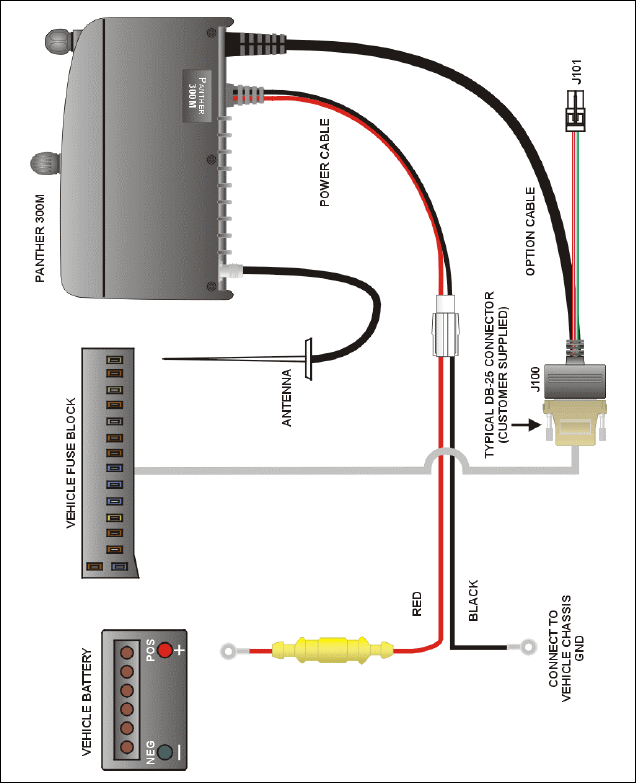
Figure 1 shows an example of a typical connection diagram. Before
beginning, plan the radio installation carefully so that it will:
" Be safe for the operator and passengers,
" Be convenient for the operator to use,
" Be neat in appearance,
" Be protected from water damage,
" Be easy to service,
" Be out of the way of auto mechanics,
" Be out of the way of passengers, and
" Allow for good air flow around the unit’s cooling fins.
For passenger safety, mount the radio securely so the unit will not
break loose in the event of a collision. This is especially important in
station wagons, vans and similar type installations where a loose
radio could be extremely dangerous to the vehicle occupants.
The procedures in this section provide a guideline for installing the
mobile radio. In some applications, it may be necessary to deviate
slightly from the recommended procedure and the order in which the
equipment is installed.
To assure the feasibility of the cable routes you plan to use, it is
suggested that you run the cables before installing the radio. Be sure
to leave some slack in each cable so that the radio may be pulled out
for servicing with the power applied.
It is recommended the unit be installed by one of the many Com-Net
Ericsson Authorized Service Centers located throughout the United
States. Personnel at these centers are experienced in installations of
this type and can provide a safe, neat, and functional installation.
STEP 2 - LOCATE THE TOOLS REQUIRED
The following tools are required to install the PANTHER 300M
Mobile Radio:
! Electric drill for drilling mounting holes

11
! Drills and circle cutters as follows:
• No. 31 (1/8-inch) drill
• 1/2-inch drill or circle cutter
• 3/4-inch circle cutter, hole saw or socket punch
! Phillips and flat-blade screwdrivers
! No. 10 Torx driver
Torx is a registered trademark of CAMCAR Division TEXTRON, Inc.
STEP 3 – EQUIPMENT PREPARATION
Mounting
This section describes the radio preparation for installation. In most
applications, the following procedures should be completed before
the radio is mounted. Depending upon the mounting location, these
procedures could become very difficult after the radio is mounted.
The preparation list includes:
! Configuring the Internal Speaker Jumper
! Configuring the Ignition Sense Line Jumper
! Connecting the Option Cable to the Radio
Read through the procedures provided in this section. If you are
satisfied with the default factory jumper settings and your installation
does not require an option cable, skip this section and go to STEP 4
– PROGRAM THE RADIO on page 16.
Removing the Top Cover and Shield
The top cover and shield must be removed to change the Internal
Speaker jumper (JP701) or the ignition sense line jumper (JP600), to
connect the option cable to the radio.
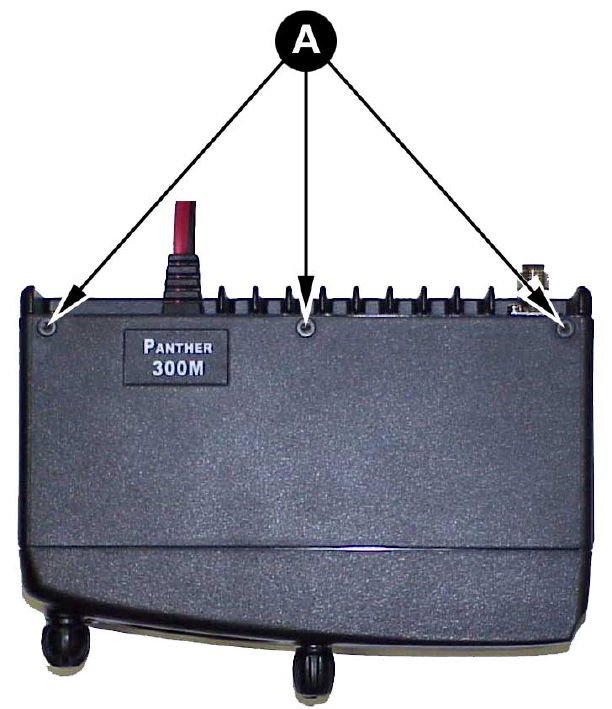
1. The top cover is secured with three screws from the bottom of
the radio. Using a No. 10 Torx driver, loosen the three screws
! on the top of the radio as shown in Figure 2.
2. Remove the two control knobs from the front of the radio.
3. Pry the cover loose from the two tabs on the bottom of the radio.
12
Figure 1 – Typical Connection Diagram
13
4. Remove the top cover by lifting the back and sliding it forward
away from the chassis.
Figure 2 – Removing Top Cover
14
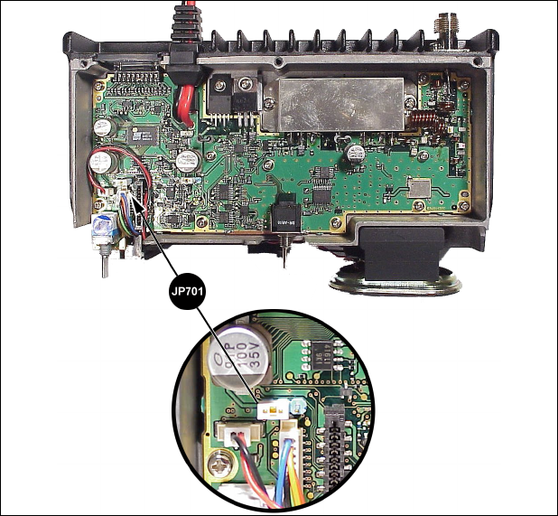
Figure 3 – Factory Default Internal Speaker Jumper Setting (Enabled)
Configure the Internal Radio Speaker Jumper (JP701)
The PANTHER 300M radio is shipped from the factory with the
internal radio speaker jumper (JP701) set to 1-2 as shown in Figure
3. This setting enables the internal radio speaker. Set the jumper to
2-3 if 1) only the External Speaker is to be enabled or 2) the
Internal/External Speaker option is to be enabled.
Configure Ignition Sense Jumper (JP600)
The Ignition Sense line is used to enable or disable transmit or car
horn alert option through the vehicle ignition switch. If the Ignition
Sense option is desired, Ignition Sense jumper JP600 must be set to
2-3. The PANTHER 300M radio is shipped from the factory with the
Ignition Sense jumper (JP600) set to 1-2 as shown in Figure 4. This
default setting disables the Ignition Sense option. If your installation
will not take advantage of the Ignition Sense line, skip this section
and proceed to the next section.