HARRIS TR-0005-A UHF-FM Land Mobile Transceiver User Manual M RK Standard and Enhanced Vehicular Charger
HARRIS CORPORATION UHF-FM Land Mobile Transceiver M RK Standard and Enhanced Vehicular Charger
HARRIS >
Contents
Install Manual Part 2
15
To use the Ignition Sense line in any application, the option cable
must be wired accordingly, see the section Connect To Ignition
Sense on page 18.
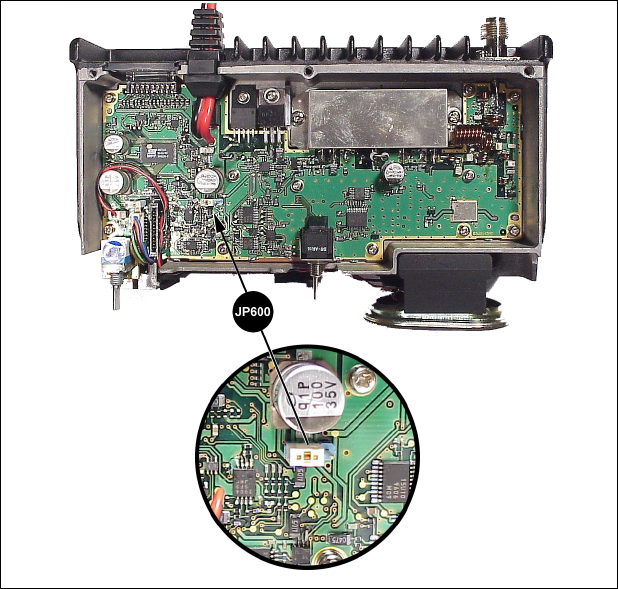
There are three parameters that define how the Ignition Sense feature
will operate - a jumper on the radio (as described above), and two
programmable parameters in the personality.
The programmable parameters enable/disable Transmission and/or
Horn Alert with respect to the vehicle ignition switch. For more
information on the personality parameters, see the On-Line Help in
Conventional ProGrammer (TQ-3389 R9A or later) or ProGrammer
(TQ-3385 R9A or later).
Figure 4 – Factory Default Settings For Jumper JP600
16
Connect Option Cable
This section applies to installations that require an option cable. The
option cable (RPM 113 7674/1) is required if you are installing:
! External Speaker ! Internal/External Speaker Option
! Car Horn Alert ! Ignition Sense
! External Modulation ! External Demodulation
To connect the option cable to the radio:
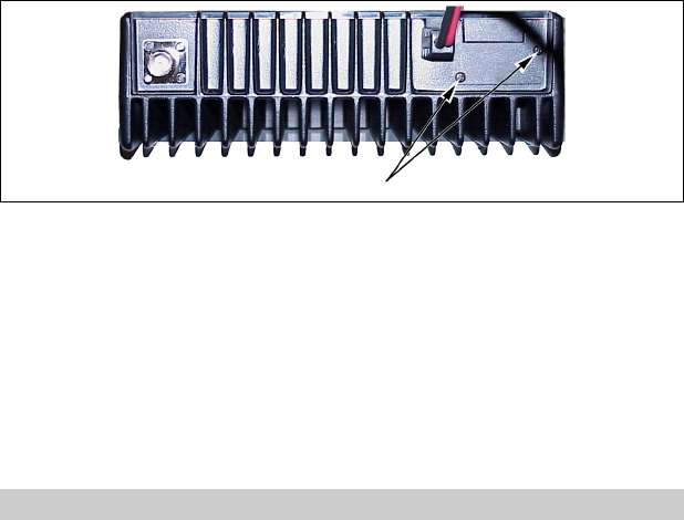
1. Remove the two Phillips screws holding the plastic cover in
place, from the back of the radio, see Figure 5.
Figure 5 – Removing Plastic Cover
2. Insert the option cable through the hole left by removing the
plastic cover. This will allow the connector to fit through the
hole in the back of the radio.
3. Plug the option cable connector into J3 on the radio circuit
board.
4. Finally attach cable with the two Phillips screws.
STEP 4 – PROGRAM THE RADIO
All radios must be programmed with a radio personality. There are
many parameters in the PANTHER 300M mobile radio that need to be
setup and defined for the radio to operate appropriately for each
application. Conventional ProGrammer (TQ-3389 R9A or later) or
ProGrammer (TQ-3385 R9A or later) is the software used to create

17
the personality for the PANTHER 300M radio. The radio personality
is a computer file that defines all the operating parameters for the
radio. For more information on programming the PANTHER 300M
radio, see the On-Line Help provided with Conventional
ProGrammer (TQ-3389 R9A or later) or ProGrammer (TQ-3385
R9A or later). Typically, the radio is programmed before it is
installed in a vehicle.
STEP 5 – INSTALL CABLES
The PANTHER 300M Mobile Radio is installed as a front mount
radio. The location of the mount, the application and the options to
be installed should be considered when planning the cable runs. The
cable diagram in Figure 1 should be referenced throughout the
installation process.
Power Cable
The power cable RPM 113 7674/10 consists of a two-wire cable, see
Figure 6. The red fused lead supplies power to the radio directly
from the vehicle battery. Ignition Sense lead, through the separate
option cable, is used by the radio electronics to determine when the
ignition switch is turned on. The black lead is the radio ground
connection.
To install the power cable:
1. Remove the fuse from the power cable.
2. When the power cable is wired directly to the vehicle’s battery it
is necessary to route the red power lead through the vehicle’s
firewall. If an existing hole is not conveniently located in the
firewall, drill a 1/2-inch hole in the firewall for the cable run and
insert a rubber grommet. This grommet is required to prevent
lead chaffing. Additional grommets may be required if the leads
must pass through shields or guards in the engine compartment.

18
Figure 6 – Power Cable RPM 113 7674/10
Route the lead away from high heat sources in the engine
compartment that may cause lead damage and introduce a fire
hazard. In addition, the lead should not be routed near electrical
noise sources such as electronic ignition modules or cruise
control modules.
3. Secure the cable at several locations within the engine
compartment to prevent possible damage to the cable.
4. Connect the BLACK lead to the vehicle chassis. Connect the
lead as close to the radio as possible. DO NOT connect the
BLACK lead to the “NEG” or “-“ battery post. Connect the
RED lead to the positive (“POS” or “+”) battery post. See
Figure 6.
#The power source must have a minimum current supply
capability of 13 amps.
Connect To Ignition Sense
The ignition sense line is used to enable or disable transmit or the
Car Horn Alert option through the vehicle ignition switch. For a
19
detailed description on how to configure the Ignition Sense line, see
the section Configure Ignition Sense Jumper on page 14.
Regardless of how the ignition sense line is configured, the option
cable must be wired as described below for the feature to work.
Connect Pin 13 of the option cable to an ignition “ON” sense point
(preferably an “Accessory” point in the vehicle fuse panel) that is
switched on when the vehicle ignition switch is in the ACCESSORY
and RUN positions. This lead should be connected so the vehicle
fuse protection is used. See Figure 6.
#The DB-25 male connector that connects to the option
cable is user-supplied.
The “Accessory” point should drop to ZERO volts when cranking
the engine and return to +12 volts after the engine is started. If a
point is chosen that drops to a voltage between zero and +12
volts, the radio may execute a power-up cycle several times
during start up. It is recommended that the terminal be
measured with a voltmeter to be sure it shuts off (goes to zero
volts) during the cranking of the engine.
Certain problems may be encountered when accessory
equipment is connected to the ignition or accessory lines of the
vehicle, where these lines may have large filter capacitors and a
leakage path present. If the radio does not turn off within a
reasonable amount of time after the ignition is turned off, first try
a different accessory or ignition A+ pick up point in the vehicle.
Many vehicles have more than one circuit that is switched by the
ignition switch, and one may be available that does not have
large filter capacitors or a leakage path present.
If a different pickup point cannot be found, then add a 470-ohm,
1-watt resistor from the ignition A+ pick point to ground. This will
discharge the capacitor(s) or reduce the leakage voltage to a low
value. Current drain through this resistor will be minimal (less
than 0.03A) when the ignition is switched on.
CAUTION
20
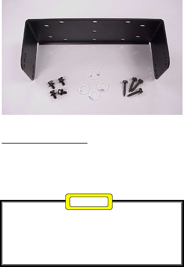
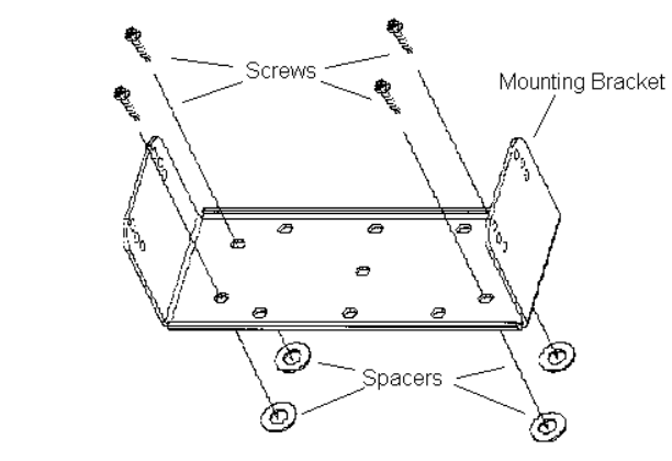
Figure 7 – Mounting Bracket and Mounting Bracket Hardware Kit
Radio Mounting Procedures
The following procedures are used to mount the radio.
1. Using the bracket as a template, mark and drill the mounting
holes using a No. 31 (1/8) drill bit. Be sure to leave enough
room at the rear of the radio unit for the cable connections and
airflow.
Be careful to avoid damaging some vital part (fuel tank,
transmission housing, etc.) of the vehicle when drilling mounting
holes. Always check to see how far the mounting screws will
extend below the mounting surface before installing.
If pilot holes must be drilled, remove all metal shavings from
drilling holes before installing screws.
2. Mount the bracket using the four 3/4” Phillips sheet metal screws
and spacers provided in the mounting bracket hardware kit.
(Refer to Figure 8.)
CAUTION
21
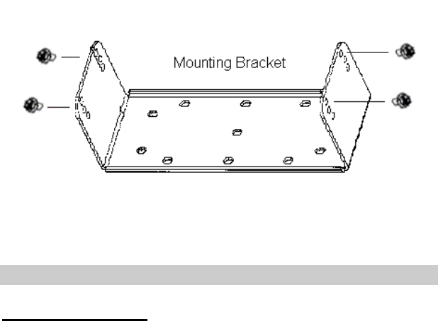
Figure 8 –Mounting Bracket Installation
3. Place the radio into the mounting bracket and secure with the
four 3/8” Phillip’s screws supplied. The radio can be fastened in
any of three different positions: parallel to the mounting surface
or tilted slightly from the parallel position. (Refer to Figure 9.)
4. Connect antenna coaxial cable to antenna connector (TNC).
5. Insert power cable into power connector running from rear of
radio unit and push until the connectors snap together.
6. Recheck all connections and then reinsert fuse into the fuse
assembly on the power cable.
22
Figure 9 – Mounting Radio to Bracket
STEP 7 – INSTALL OPTIONS AND ACCESSORIES
Radio Option Cable
The radio option cable (RPM 113 7674/1) is required if you are
installing:
! External Speaker ! Internal/External Speaker Option
! Car Horn Alert ! Ignition Sense
! External Modulation ! External Demodulation
The section STEP 3 – EQUIPMENT PREPARATION, on page
11, describes how to connect the option cable to the radio. The other
end of the option cable consists of a standard female DB-25
connector, which is used to connect to the optional accessories listed
above. Table 2 provides a description for each input and output on
the radio option connector J603.

23
Table 2 – Radio Option Connector P3 Interface Description
DB-25
Pin No
(J100)
Pin No
(P3) I/O Description
21---
Ground:
! Audio Ground
52I
Internal Speaker Input #1:
! 5W across Internal Speaker
63O
Audio Amp Output #1:
! Vo ≈ 6.6 VDC
18 4 O Audio Amp Output #2 to Internal or External Speaker
! Vo ≈ 6.6 VDC; 10W maximum across External
Speaker
19 5 I External Mic Input:
! 300-3000 Hz
! Input level @ 1kHz for 60% of RSD: 82 ± 28 mVRMS
(if external audio source has Ro=600Ω)
! Input level @ 1kHz for 60% of RSD: 41 ± 14 m VRMS
(if external audio source has Ro<1Ω)
76I
External Mod Input:
! 5-10,000 Hz (3 db BW)
! Modulation-Sensitivity: 4.2 kHz/Vrms ± 3dB
20 7 O Switched DC Output:
! Icc=500 mA Max
88I
Push To Talk:
! TX ON: Low
! TX OFF: Open
21 9 I Mic Hookswitch:
! “Disable” or “Enable” is selected by PC Programmer
! Hookswitch ON: Low
! Hookswitch OFF: Open
910O
Rx Discriminator Detect Audio:
! 20-4,000 Hz (3 dB Bandwidth)
! 75 m VRMS ±3 dB into a 10K ohm load
22 11 --- Ground
10 12 I Internal Mic Mute:
! Mute ON: Low
! Mute OFF: Open
23 13 O Radio UnSquelch:
! Squelch Open: Low
! Squelch Close: High
! RL = 4.7 kohms
11 14 Spare

24
Table 2 - Radio Option Connector P3 Interface Description Con’t
DB-25
Pin No
(J100)
Pin No
(P3) I/O Description
24 15 O (1) HORN CONTROL At Signaling Mode
Display In Menu Action
On Enable
Off Disable
! When select “ON”(enable) and a correct T99 Individual
Call is received, the output of pin 15 is “low.”
! Horn Alarm ON : Low
! Horn Alarm OFF: Open
(2) SPEAKER SELECT INTERNAL/EXTERNAL
! Enabling or disabling of the Internal/External Speaker
option is done by proper setting of an internal jumper in
the mobile radio.
! Internal: Low
! External: Open
! For relay control Io_max = 150mA
! **“HORN CONTROL” or “SPEAKER SELECT” is
selected by PC ProGrammer.
Note: Internal and external speaker do not operate
simultaneously.
12 16 I Data Communication Input (Test Mode)
! TTL Level
25 17 O Data Communication Output (Test Mode)
! TTL Level
13 18 I Ignition Sense
! 13.6VDC
! Io_max = 100 mA
Internal Mic Mute (DB25-10) must be grounded when applying
audio to external Mic Input (DB25-19).
External Mic Input (DB25-19) has the same audio characteristics
as the Front Panel Mic Jack. External Mod Input (DB25-7) has
no pre-emphasis or modulation limiting.
NOTE
25
External Speaker – 19A149590P11
The external speaker kit includes a 4-ohm, 10 Watt rated speaker and
a radio option cable. To connect an external speaker, the radio option
cable (RPM 113 7674/1) must be installed and connected to the
radio.
1. Mount the speaker so it is directed to the operator but does not
interfere with the operator’s vision. It also should not present a
hazard in the event of an accident. The speaker may be mounted
on the lower edge of the instrument panel, the firewall, or above
the windshield in some trucks.
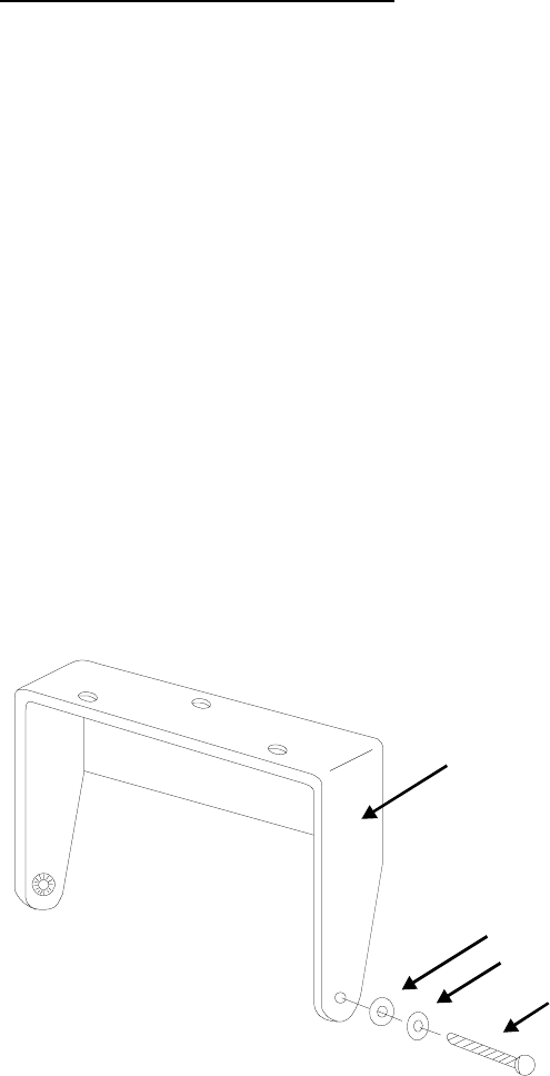
2. Use the mounting bracket as a template for locating the
mounting holes, and mount the speaker as shown in Figure 10.
3. Refer to Figure 9 for instructions on connecting the External
Speaker option and Figure 10 for instructions on connecting the
Internal/External Speaker option.
MOUNTING
BRACKET
MACHINE
SCREW
FLAT WASHER
LOCK WASHER
Figure 10 - Mounting the External Speaker
26
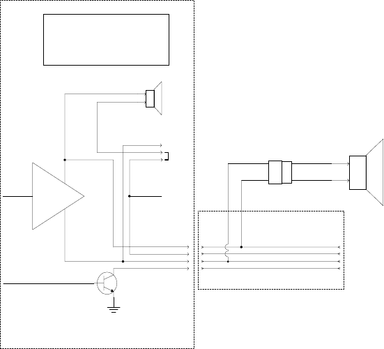
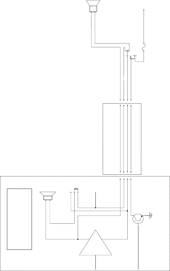
PANTHER 300M EXTERNAL
SPEAKER OPTION
WHEN THE EXTERNAL SPEAKER OPTION IS APPLIED,
AUDIO FROM THE SPEAKER AMP LEAVES THE RADIO
ON OPTION CONNECTOR PINS 3 AND 4 AND GOES TO
J101. THE EXTERNAL SPEAKER'S CABLE IS
CONNECTED TO J101.
JUMPER POSITIONS
1-2 USED WHEN THERE IS NO
EXTERNAL SPEAKER OPTION
2-3 USED WHEN THERE IS AN
EXTERNAL SPEAKER OPTION
-
+
AUDIO I N
RADIO AUDIO
AMP
INTERNAL
SPEAKER
3 PIN
JUMPER
uP PORT
OPEN COLLECTOR
TRANSISTOR
HORN/SPKR 15
SPKR 1 3
INT SPKR 1 2
SPKR 2 4
INT SPKR 1
3
2
SPKR 1 1
SPKR 2
SPKR 2
SPKR 1
8 OHM
5 WATT
INT
EXT
300M RADIO
RPM 113 7674/1
OPTION CABLE
RADIO
CONNECTOR DB 25
CONNECTOR
4
2
3
15
18
5
6
24
P3 J100
4 OHM
10 WATT
J101
SPKR 1
SPKR 2
Figure 11 – External Speaker Option
27
PANTHER 300M INTERNAL/EXTERNAL
SPEAKER OPTION
(THIS SCHEMATIC ALSO APPLIES TO PUBLIC ADDRESS)
WHEN THE INTERNAL/EXTERNAL SPEAKER OR PUBLIC ADDRESS OPTIONS ARE APPLIED. AUDIO FROM THE SPEAKER AMP
LEAVES THE RADIO ON OPTION CONNECTOR PIN 3 AND GOES TO THE COMMON SIDE OF AN SPDT RELAY.
WHEN INTERNAL SPEAKER IS SELECTED, THE RELAY FLOATS. THE NORMALLY CLOSED RELAY CONTACT APPLIES AUDIO
BACK INTO THE RADIO TO THE INTERNAL SPEAKER ON OPTION CONNECTOR PIN 2. (IT IS ASSUMED THE INTERNAL 3-PIN
JUMPER IS ON PINS 2 & 3.)
WHEN THE EXTERNAL SPEAKER IS SELECTED, THE RELAY IS ENGAGED. AUDIO IS APPLIED TO THE NORMALLY OPEN
CONTACT THAT THEN CONNECTS TO THE EXTERNAL SPEAKER.
ONLY THE SPKR_1 SIDE OF THE AUDIO AMP'S OUTPUT IS SWITCHED. THE SPKR_2 SIDE OF THE AUDIO AMP IS
CONNECTED TO BOTH SPEAKERS.
OUR SPEAKER RELAY KIT INCLUDES THE 19A149299P1 RELAY, WIRE, AND A FUSE. THE CUSTOMER IS RESPONSIBLE FOR
INSTALLING AND PROVIDING POWER TO THE RELAY.
JUMPER POSITIONS
1-2 USED WHEN THERE IS NO INTERNAL/
EXTERNAL SPEAKER OPTION
2-3 USED WHEN THERE IS AN INTERNAL/
EXTERNAL SPEAKER OPTION
-
+
AUDIO IN
RADIO AUDIO
AMP
INTERNAL
SPEAKER
3 PIN
JUMPER
uP PORT
OPEN COLLECTOR
TRANSISTOR
HORN/SPKR 15
SPKR 1 3
INT SPKR 1 2
SPKR 2 4
INT SPKR 1
3
2
SPKR 1 1
SPKR 2
SPKR 2
SPKR 1
8 OHM
5 WATT
INT
EXT
300M RADIO
RPM 113 7674/1
OPTION CABLE
RADIO
CONNECTOR DB 25
CONNECTOR
4
2
3
15
18
5
6
24
P3 J100
AUDIO OUT (SPKR_2 SIDE OF AUDIO AMP)
INTERNAL AUDIO BACK INTO RADIO
AUDIO OUT (SPKR_1 SIDE OF AUDIO AMP)
RELAY CONTROL LINE COM
SPDT RELAY
(19A149299P1)
SPEAKER RELAY
FUSE
1A
BATTERY A+
OR
IGNITION A+
EXTERNAL
SPEAKER
4 OHM
10 WATT
EXT SPEAKER AUDIO
SPKR 2
NO
NO
(LOW FOR EXTERNAL SPEAKER)
Figure 12 – Internal/External Speaker Relay

28
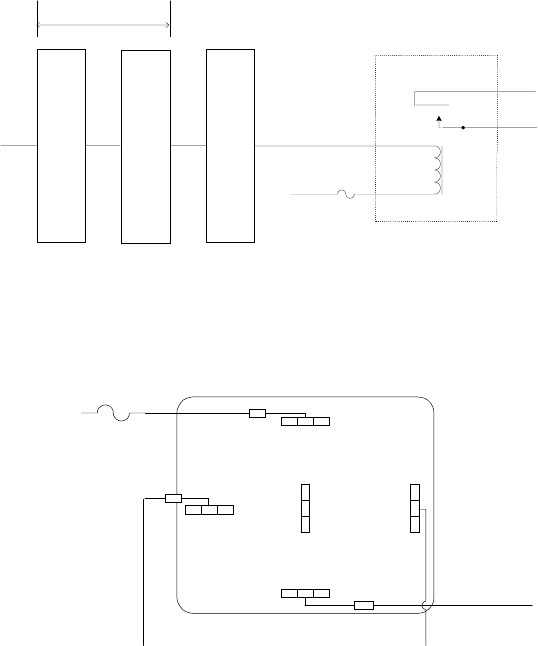
Alarm (Horn) Relay Kit - 19A705499P1
To connect the alarm relay kit, the radio option cable (RPM 113
7674/1) must be installed and connected to the radio. The alarm
relay kit option consists of the following items:
! Relay (19A149299P1)
! Fuse holder
! Fuse, 1 amp, 250 volt
! 4 feet red wire, AWG #18 with Ring Tongue Terminal for 3/ 8
stud
! 6 feet black wire, AWG #18 with Molex #39- 00- 0060 terminal
! (5) Insulated 1/ 4 inch spade tab receptacles
! Ring Tongue Terminal for 3/ 8 inch stud
! #8 x 3/ 4 long Type A sheet metal screw
! Nut Plate for #8 screw
To install the Alarm (Horn) Relay Kit
1. Fasten the relay in the desired location, close to the voltage
source, using one #8 x 3/ 4 inch self- tapping screw.
2. Crimp an insulated 1/ 4 inch spade tab receptacle to one end of
the #18 red wire.
3. Connect the receptacle to relay lug #86. Cut the red lead so the
fuse assembly is close to the voltage source. Install the fuse
holder. Attach the other end of the fuse lead to the voltage source
with appropriate hardware. See Figure 14.
4. From the radio option cable, take the green/white wire and crimp
an insulated 1/ 4 inch spade tab receptacle. Connect the
receptacle to relay lug #85.
5. Connect the horn or light circuit to lugs #30 and #87 (not 87a)
using the insulated 1/ 4 inch spade tab receptacles.
#The relay contact make/ break current and voltage rating is
30 amps at 16 volts.
29
OPTION CABLE
RPM 113 7674/1
PIN 15
ON
18 PIN CONNECTOR
DB-25 CONNECTOR
(FEMALE)
P3 J100
PIN 24
DB-25 CONNECTOR (MALE)
TO BE SUPPLIED BY CUSTOMER
NO
COM To Horn Circuit
To Horn Circuit
RELAY
19A149299P1
30
87
85
FUSE
(1A) 86
BATTERY A+
Figure 13 - External Car Alert
86
87
87a
30
85
TO HORN CIRCUIT
TO RADIO OPTION CABLE
GREEN/WHITE WIRE
FUSE (1A)
BATTERY A+
Figure 14 - External Alarm Relay
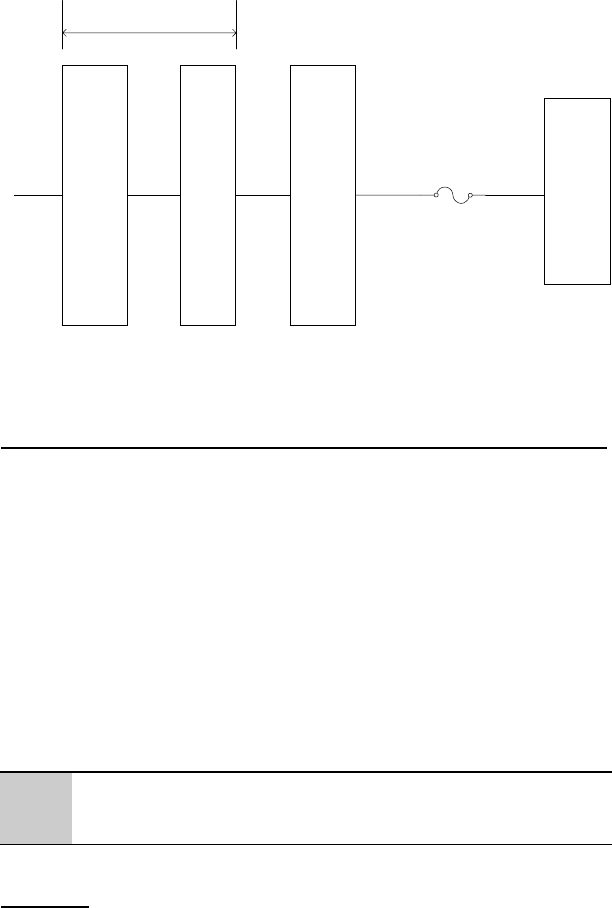
30
OPTION CABLE
RPM 113 7674/1
PIN 18
IGNITION
SENSE
18 PIN CONNECTOR
DB-25 CONNECTOR
(FEMALE)
P3 J100
PIN 13
DB-25 CONNECTOR (MALE)
TO BE SUPPLIED BY CUSTOMER
FUSE 1A (OPTIONAL)
VEHICLE FUSE BLOCK
Figure 15 – Ignition Sense Option
Microphone Hanger/Hook Switch Mounting – 344A4678P1
The microphone hanger or Hook Switch should be mounted in a
location convenient to the operator where it will not interfere with
the safe operation of the vehicle or be a hazard to the vehicle
passengers. The hanger or hook switch is designed to mount with the
open end of the mounting button slot pointed upward.
1. Use the hanger or Hook Switch as a template to mark and drill
the mounting holes. Mount the hanger or hook switch with the
self-tapping screws provided.
2. Connect microphone connector to connector on control unit and
secure with captive screw.
#Do not torque microphone connector screw greater than 2 in-
lb. Alternatively, finger tight plus 1/4 turn is acceptable.
Antenna
Installation instructions for the antenna are packaged with the
antenna. The antenna must be installed in accordance with good
engineering practice for optimum results.

31
Typical Mobile Antenna Installation
A permanent mount type of antenna should be located in the center
of the roof or center of rear deck.
The Maximum Permissible Exposure limit is a radius of 55
inches (or 138 cm) for roof or rear deck installations per OET
Bulletin 65 of the FCC. This estimate is made assuming the
maximum capable transmit power of the radio and an antenna
with a maximum gain of 3 dBd. A maximum 50% transmit duty
cycle is also assumed, due to the push-to-talk status of this
mobile.
WARNING
SEE “MAXIMUM PERMISSIBLE EXPOSURE
LIMITS” AND “SAFETY TRAINING
INFORMATION” SECTIONS AT THE
BEGINNING OF THIS MANUAL FOR
FURTHER INFORMATION REGARDING
MAXIMUM PERMISSIBLE EXPOSURE
(MPE) LIMITS OF RF RADIATION
ABSORPTION SET BY THE FCC.
Try to route the cable away from locations where it will be exposed
to heat, sharp edges or mechanical damage, and where it will be out
of the way of the driver, passengers or vehicles mechanics. Wherever
possible, existing holes in the trunk wall, and the channels above or
beneath doors and window columns should be utilized.
Avoid routing the antenna cable near any electronic modules or
along side any vehicle wiring.
Connect the antenna cable to the TNC connector on the radio being
careful not to twist the cable.

32
Typical Desktop Base Station Antenna Installation
For desktop base station configurations, a typical building roof
top/tower installation may be used.
The Maximum Permissible Exposure limit is a radius of 77
inches (or 195 cm) for typical desktop base station configurations
per OET Bulletin 65 of the FCC. This estimate is made
assuming the maximum capable transmit power of the radio and
an antenna with a maximum gain of 6 dBd. A maximum 50%
transmit duty cycle is also assumed, due to the push-to-talk
status of this mobile.
Noise Suppression Kit - Option KMPD1A (19A148539G1)
Refer to the noise suppression kit option installation manual that is
included with this option.
33
NOTES
34
NOTES
35
NOTES
Com-Net Ericsson Critical Radio Systems, Inc.
P.O. Box 2000
Lynchburg, Virginia 24501
1-800-528-7711 (Outside USA, 804-592-7711) Printed in U.S.A.