HARRIS TR-0035-E M7100 VHF Mobile, 8-50W User Manual MM102342V1RevCp1
HARRIS CORPORATION M7100 VHF Mobile, 8-50W MM102342V1RevCp1
HARRIS >
Contents
Installation Manual

Installation Manual
MM102342V1
Rev. C, Dec-04
M7100IP Series
Mobile Radio

2
REVISION HISTORY
REV DATE SUMMARY OF CHANGES
A Feb 2004 Initial release
B Apr. 2004 Add MPE and FCC information for VHF, UHF-L, UHF-H,
and 800 MHz M7100IP radio.
C Dec. 2004 Added MPE and FCC information for 50W VHF mobile
radio.
M/A-COM Technical Publications would particularly appreciate feedback on any errors found in this document
and suggestions on how the document could be improved. Submit your comments and suggestions to:
Wireless Systems Business Unit or fax your comments to: (434) 455-6851
M/A-COM, Inc.
Technical Publications or e-mail us at: techpubs@tycoelectronics.com
221 Jefferson Ridge Parkway
Lynchburg, VA 24501
SUPPLEMENTARY INFORMATION
At this time, the M7100IP mobile radio may not be operated while in a desktop station in the
European Community since it does not meet immunity requirements when operated in this mode.
The M7100IP mobile radio can be used in both trunked and conventional applications.
ACKNOWLEDGEMENTS
This device is made under license under one or more of the following US patents: 4,590,473;
4,636,791; 5,148,482; 5,185,796; 5,271,017; 5,377,229; 4,716,407; 4,972,460; 5,502,767;
5,146,497; 5,164,986; 5,185,795.
The voice coding technology embodied in this product is protected by intellectual property rights
including patent rights, copyrights, and trade secrets of Digital Voice Systems, Inc. The user of
this technology is explicitly prohibited from attempting to decompile, reverse engineer, or
disassemble the Object Code, or in any other way convert the Object Code into human-readable
form.
CREDITS
EDACS is a registered trademark and ProGrammer, SCAT, Failsoft, ProSound, ProScan, Aegis,
ProFile, ProVoice, and G-STAR are trademarks of M/A-COM, Inc.
Torx is a registered trademark of CAMCAR Division TEXTRON, Inc.
POZIDRIV is a registered trademark of Phillips International Company.
IMBE is a registered trademark of Digital Voice Systems, Inc.
Molex is a registered trademark of Molex Incorporated.
All other brand and product names are trademarks, registered trademarks, or service marks of their
respective holders.
NOTICE!
This manual covers M/A-COM, Inc. products manufactured and sold by M/A-COM, Inc.
NOTICE!
Repairs to this equipment should be made only by an authorized service technician or facility
designated by the supplier. Any repairs, alterations, or substitution of recommended parts made
by the user to this equipment not approved by the manufacturer could void the user's authority to
operate the equipment in addition to the manufacturer's warranty.
This manual is published by M/A-COM, Inc., without any warranty. Improvements and changes to this manual
necessitated by typographical errors, inaccuracies of current information, or improvements to programs and/or
equipment, may be made by M/A-COM, Inc., at any time and without notice. Such changes will be
incorporated into new editions of this manual. No part of this manual may be reproduced or transmitted in any
form or by any means, electronic or mechanical, including photocopying and recording, for any purpose,
without the express written permission of M/A-COM, Inc.
Copyright© 2004 M/A-COM, Inc. All rights reserved.

3
TABLE OF CONTENTS Page
1 SAFETY SYMBOL CONVENTIONS ........................................................4
2 RF ENERGY EXPOSURE INFORMATION ............................................5
2.1 RF ENERGY INFORMATION AND REQUIREMENTS ................5
2.2 COMPLIANCE WITH RF EXPOSURE STANDARDS...................6
3 OPERATION SAFETY RECOMMENDATIONS.....................................9
3.1 TRANSMITTER HAZARDS ............................................................9
3.2 SAFE DRIVING RECOMMENDATIONS .....................................10
4 OPERATING RULES AND REGULATIONS.........................................11
4.1 OPERATING TIPS ..........................................................................12
5 INTRODUCTION.......................................................................................13
6 UNPACKING AND CHECKING EQUIPMENT ....................................14
7 PLANNING THE INSTALLATION.........................................................19
8 EQUIPMENT REQUIRED........................................................................21
9 INSTALLATION........................................................................................22
9.1 RUNNING CABLES .......................................................................22
9.2 CONTROL UNIT MOUNTING ......................................................30
9.3 PIGTAIL BRACKET.......................................................................30
9.4 SPEAKER........................................................................................33
9.5 MIC HANGER AND/OR HOOKSWITCH MOUNTING...............34
9.6 SIREN AND LIGHT........................................................................34
9.7 RADIO MOUNTING AND FINAL HOOK-UP..............................35
10 DUAL CONTROL UNIT INSTALLATION............................................39
10.1 PRE-INSTALLATION PROGRAMMING PROCEDURE
WITH PROGRAMMER - FRONT MOUNT...................................40
10.2 PRE-INSTALLATION PROGRAMMING PROCEDURE
WITH PROGRAMMER - REMOTE MOUNT ...............................42
10.3 INSTALLATION INSTRUCTIONS FOR FRONT MOUNT
DUAL CONTROL UNITS ..............................................................45
10.4 INSTALLATION INSTRUCTIONS FOR REMOTE MOUNT
DUAL CONTROL UNITS ..............................................................48
10.5 FIELD PROGRAMMING – DUAL CONTROL UNITS ................51
11 DUAL RADIO UNITS................................................................................56
11.1 PRE-INSTALLATION PROGRAMMING PROCEDURE
WITH PROGRAMMER – DUAL RADIO UNITS .........................56
11.2 INSTALLATION INSTRUCTIONS FOR FRONT/REMOTE
MOUNT DUAL RADIO CONFIGURATION ................................58
11.3 INSTALLATION INSTRUCTIONS REMOTE/REMOTE
MOUNT DUAL RADIO CONFIGURATION ................................60
11.4 FIELD PROGRAMMING – DUAL RADIO UNITS.......................61
11.5 ANTENNA.......................................................................................66
12 WARRANTY...............................................................................................67
4
1 SAFETY SYMBOL CONVENTIONS
The following conventions are used throughout this manual to alert the user to
general safety precautions that must be observed during all phases of
operation, service, and repair of this product. Failure to comply with these
precautions or with specific warnings elsewhere in this manual violates safety
standards of design, manufacture, and intended use of the product. M/A-
COM, Inc. assumes no liability for the customer’s failure to comply with
these standards.
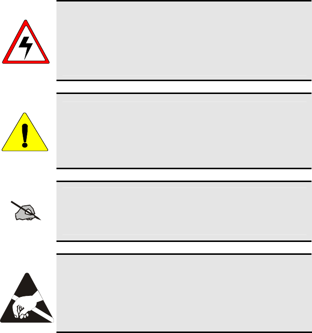
WARNING
The WARNING symbol calls attention to a procedure,
practice, or the like, which, if not correctly performed or
adhered to, could result in personal injury. Do not proceed
beyond a WARNING symbol until the conditions identified
are fully understood or met.
CAUTION
The CAUTION symbol calls attention to an operating
procedure, practice, or the like, which, if not performed
correctly or adhered to, could result in damage to the
equipment or severely degrade the equipment performance.
NOTE
The NOTE symbol calls attention to supplemental
information, which may improve system performance or
clarify a process or procedure.
The ESD symbol calls attention to procedures, practices, or
the like, which could expose equipment to the effects of
Electro-Static Discharge. Proper precautions must be taken
to prevent ESD when handling circuit modules.

5
2 RF ENERGY EXPOSURE INFORMATION
2.1 RF ENERGY EXPOSURE AWARENESS,
CONTROL INFORMATION, AND OPERATION
INSTRUCTIONS FOR FCC OCCUPATIONAL USE
REQUIREMENTS
BEFORE USING YOUR MOBILE TWO-WAY RADIO, READ THIS
IMPORTANT RF ENERGY AWARENESS AND CONTROL
INFORMATION AND OPERATIONAL INSTRUCTIONS TO ENSURE
COMPLIANCE WITH THE FCC’S RF EXPOSURE GUIDELINES.
NOTICE: This radio is intended for use in occupational/controlled
conditions, where users have full knowledge of their exposure and can
exercise control over their exposure to meet FCC limits. This radio
device is NOT authorized for general population, consumer, or any other
use.
CAUTION
Changes or modifications not expressly approved by M/A-
COM, Inc. could void the user's authority to operate the
equipment.
This two-way radio uses electromagnetic energy in the radio frequency (RF)
spectrum to provide communications between two or more users over a
distance. It uses RF energy or radio waves to send and receive calls. RF
energy is one form of electromagnetic energy. Other forms include, but are
not limited to, electric power, sunlight, and x-rays. RF energy, however,
should not be confused with these other forms of electromagnetic energy,
which, when used improperly, can cause biological damage. Very high levels
of x-rays, for example, can damage tissues and genetic material.

6
Experts in science, engineering, medicine, health, and industry work with
organizations to develop standards for exposure to RF energy. These
standards provide recommended levels of RF exposure for both workers and
the general public. These recommended RF exposure levels include
substantial margins of protection. All two-way radios marketed in North
America are designed, manufactured, and tested to ensure they meet
government established RF exposure levels. In addition, manufacturers also
recommend specific operating instructions to users of two-way radios. These
instructions are important because they inform users about RF energy
exposure and provide simple procedures on how to control it. Please refer to
the following websites for more information on what RF energy exposure is
and how to control your exposure to assure compliance with established RF
exposure limits.
http://www.fcc.gov/oet/rfsafety/rf-faqs.html
http://www.osha.gov./SLTC/radiofrequencyradiation/index.html
2.1.1 Federal Communications Commission
Regulations
Your M/A-COM, Inc. M7100IP mobile two-way radio is designed and tested
to comply with the FCC RF energy exposure limits for mobile two-way radios
before it can be marketed in the United States. When two-way radios are used
as a consequence of employment, the FCC requires users to be fully aware of
and able to control their exposure to meet occupational requirements.
Exposure awareness can be facilitated by the use of a label directing users to
specific user awareness information. Your M/A-COM, Inc. M7100IP two-way
radio has an RF exposure product label. Also, your M7100IP Installation and
Operator’s Manuals include information and operating instructions required to
control your RF exposure and to satisfy compliance requirements.
2.2 COMPLIANCE WITH RF EXPOSURE
STANDARDS
Your M/A-COM, Inc. M7100IP mobile two-way radio is designed and tested
to comply with a number of national and international standards and
guidelines (listed below) regarding human exposure to RF electromagnetic
energy. This radio complies with the IEEE and ICNIRP exposure limits for
occupational/controlled RF exposure environment at duty factors of up to
50% talk-50% listen and is authorized by the FCC for occupational use. In
terms of measuring RF energy for compliance with the FCC exposure
guidelines, your radio antenna radiates measurable RF energy only while it is
transmitting (talking), not when it is receiving (listening) or in standby mode.
7
Your M/A-COM, Inc. M7100IP mobile two-way radio complies with the
following RF energy exposure standards and guidelines:
• United States Federal Communications Commission (FCC), Code of
Federal Regulations; 47 CFR §§ 2 sub-part J.
• American National Standards Institute (ANSI)/Institute of Electrical
and Electronic Engineers (IEEE) C95.1-1992.
• Institute of Electrical and Electronic Engineers (IEEE) C95.1-1999.
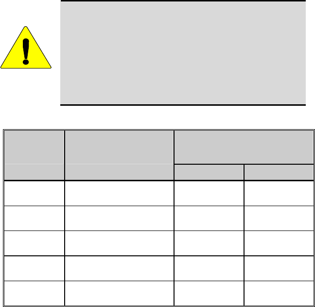
CAUTION
Table 2-1 lists the recommended minimum lateral distance
for a controlled environment and for unaware bystanders in
an uncontrolled environment, from transmitting types of
antennas (i.e., monopoles over a ground plane, or dipoles)
at rated radio power for mobile radios installed in a vehicle.
Transmit only when unaware bystanders are at least the
uncontrolled recommended minimum lateral distance away
from the transmitting antenna.
Table 2-1: Rated Power and Recommended Minimum Lateral Distance
RECOMMENDED MINIMUM
LATERAL DISTANCE FROM
TRANSMITTING ANTENNA
MOBILE RADIO
FREQUENCY
SPLIT
RATED POWER OF
VEHICLE-INSTALLED
MOBILE TWO-WAY RADIO
CONTROLLED UNCONTROLLED
VHF 110 Watts
(Antenna P/N: 19B209568P6) 92.87 cm 207.67 cm
VHF 50 Watts
(Antenna P/N: AN102800V1/V2) 63.52 cm 142.00 cm
UHF–L 50 Watts
(Antenna P/N: AN102800V1) 57.93 cm 129.50 cm
UHF-H 50 Watts
(Antenna P/N: AN102800V1) 46.64 cm 104.29 cm
800 MHz 35 Watts
(Antenna P/N: AN102800V1) 32.60 cm 72.90 cm

8
2.2.1 Mobile Antennas
NOTE
This device must not be co-located or operated in conjunction
with any other antenna or transmitter.
Install the radio’s antenna (refer to Table 2-1 for applicable antenna part
numbers) in the center of the vehicle’s roof. These mobile antenna
installation guidelines are limited to metal body motor vehicles or vehicles
with appropriate ground planes. The antenna installation should additionally
be in accordance with the following.
• The requirements of the antenna manufacturer/supplier included with the
antenna.
• Instructions in the M7100IP Radio Installation Manual, including
minimum antenna cable lengths.
• The installation manual providing specific information of how to install
the antennas to facilitate recommended operating distances to all
potentially exposed persons.
Use only the M/A-COM approved/supplied antenna(s) or approved
replacement antenna. Unauthorized antennas, modifications, or attachments
could damage the radio and may violate FCC regulations.
2.2.2 Approved Accessories
This radio has been tested and meets the FCC RF guidelines when used with
the M/A-COM accessories supplied or designated for use with this product.
Use of other accessories may not ensure compliance with the FCC’s RF
exposure guidelines, and may violate FCC regulations.
For a list of M/A-COM approved accessories refer to the product manuals,
M/A-COM’s Products and Services Catalog, or contact M/A-COM at 1-800-
528-7711.
2.2.3 Contact Information
For additional information on exposure requirements or other information,
contact M/A-COM, Inc. at 1-800-528-7711 or at http://www.macom-
wireless.com.

9
3 OPERATION SAFETY RECOMMENDATIONS
3.1 TRANSMITTER HAZARDS
WARNING
The operator of any mobile radio should be aware of certain
hazards common to the operation of vehicular radio
transmitters. A list of several possible hazards is given.
• Explosive Atmospheres – Just as it is dangerous to fuel a vehicle with
the motor running, similar hazards exist when operating a mobile radio.
Be sure to turn the radio off while fueling a vehicle. Do not carry
containers of fuel in the trunk of a vehicle if the radio is mounted in the
trunk.
Areas with potentially explosive atmosphere are often, but not
always, clearly marked. Turn OFF your radio when in any area with
a potentially explosive atmosphere. It is rare, but not impossible that
the radio or its accessories could generate sparks.
• Interference to Vehicular Electronics Systems – Electronic fuel
injection systems, electronic anti-skid braking systems, electronic cruise
control systems, etc., are typical electronic systems that can malfunction
due to the lack of protection from radio frequency energy present when
transmitting. If the vehicle contains such equipment, consult the dealer
and enlist their aid in determining the expected performance of electronic
circuits when the radio is transmitting.
• Electric Blasting Caps – To prevent accidental detonation of electric
blasting caps, DO NOT use two-way radios within 1000 feet of blasting
operations. Always obey the “Turn Off Two-Way Radios” signs posted
where electric blasting caps are being used. (OSHA Standard: 1926-900)
• Liquefied Petroleum (LP) Gas Powered Vehicles – Mobile radio
installations in vehicles powered by liquefied petroleum gas with the LP
gas container in the trunk or other sealed-off space within the interior of
the vehicle must conform to the National Fire Protection Association
standard NFPA 58 requiring:
¾ The space containing the radio equipment shall be isolated by a seal
from the space containing the LP gas container and its fittings.
¾ Outside filling connections shall be used for the LP gas container.
¾ The LP gas container shall be vented to the outside of the vehicle.
10
3.2 SAFE DRIVING RECOMMENDATIONS
(Recommended by AAA)
• Read the literature on the safe operation of the radio.
• Keep both hands on the steering wheel and the microphone in its hanger
whenever the vehicle is in motion.
• Place calls only when the vehicle is stopped.
• When talking from a moving vehicle is unavoidable, drive in the slower
lane. Keep conversations brief.
• If a conversation requires taking notes or complex thought, stop the
vehicle in a safe place and continue the call.
• Whenever using a mobile radio, exercise caution.

11
4 OPERATING RULES AND REGULATIONS
Two-way FM radio systems must be operated in accordance with the rules
and regulations of the local, regional, or national government.
In the United States, the M7100IP Series mobile radio must be operated in
accordance with the rules and regulations of the Federal Communications
Commission (FCC). As an operator of two-way radio equipment, you must
be thoroughly familiar with the rules that apply to your particular type of
radio operation. Following these rules helps eliminate confusion, assures the
most efficient use of the existing radio channels, and results in a smoothly
functioning radio network.
When using your two-way radio, remember these rules:
• It is a violation of FCC rules to interrupt any distress or emergency
message. As your radio operates in much the same way as a telephone
“party line,” always listen to make sure that the channel is clear before
transmitting. Emergency calls have priority over all other messages. If
someone is sending an emergency message – such as reporting a fire or
asking for help in an accident – KEEP OFF THE AIR!
• The use of profane or obscene language is prohibited by Federal law.
• It is against the law to send false call letters or false distress or emergency
messages. The FCC requires that you keep conversations brief and
confine them to business. To save time, use coded messages whenever
possible.
• Using your radio to send personal messages (except in an emergency) is a
violation of FCC rules. You may send only those messages that are
essential for the operation of your business.
• It is against Federal law to repeat or otherwise make known anything you
overhear on your radio. Conversations between others sharing your
channel must be regarded as confidential.
• The FCC requires that you identify yourself at certain specific times by
means of your call letters. Refer to the rules that apply to your particular
type of operation for the proper procedure.
• No changes or adjustments shall be made to the equipment except by an
authorized or certified electronics technician.
IMPORTANT!
Under U.S. law, operation of an unlicensed radio
transmitter within the
j
urisdiction of the United
States may be punishable by a fine of up to $10,000,
imprisonment for up to two (2) years, or both.
12
4.1 OPERATING TIPS
The following conditions tend to reduce the effective range of two-way radios
and should be avoided whenever possible:
• Operating the radio in areas of low terrain, or while under power lines or
bridges
• Obstructions such as mountains and buildings
• In areas where transmission or reception is poor, some improvement can
be obtained by moving a few yards in another direction or moving to a
higher elevation.
13
5 INTRODUCTION
This manual contains installation instructions for the M7100IP Series Mobile
Radio Unit and associated accessories. These instructions cover the mounting
and cabling of the radio; interconnection and wiring diagrams are provided for
reference.
The radio should be programmed prior to installation. Refer to the Software
Release Notes with TQS3385 or TQS3389 for equipment and compatibility
requirements.
Shop Programming Cable TQ3409 (CA101288V15)
Field Programming Cable TQ3410 (CA101287V1)
ProGrammer™ Software TQS3385
or
Conventional ProGrammer Software TQS3389
14
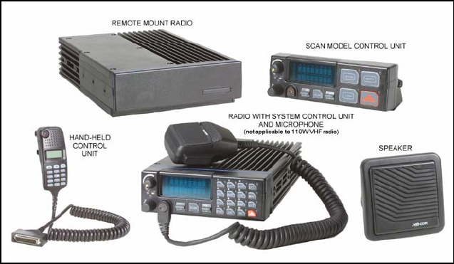
6 UNPACKING AND CHECKING EQUIPMENT
Carefully unpack the radio and identify each item in the shipping container
(some items that typically ship are listed below). If damage has occurred to
the equipment during shipment, file a claim with the carrier immediately.
Refer to Table 6-1 and Table 6-2 in this manual or to M/A-COM’s Products
and Services catalog for options and accessories for the M7100IP Series
Mobile Radio.
• M7100IP Series Mobile Radio Unit
• Control Unit
• Microphone
• Speaker
• Power Cable
• Control Cable
• Front Mount Bracket Kit
or
• Remote Mount Bracket Kit
with
• Control Unit Mount Kit
• Operator's Manual (MM102341V1)
• Installation Manual (MM102342V1)
Figure 6-1 – M7100IP Series Mobile Radio Components
15
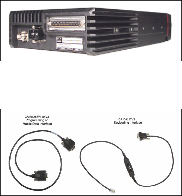
Figure 6-2: Rear Angle View of Radio (110W VHF Shown)
Figure 6-3: – Interface Cables
16
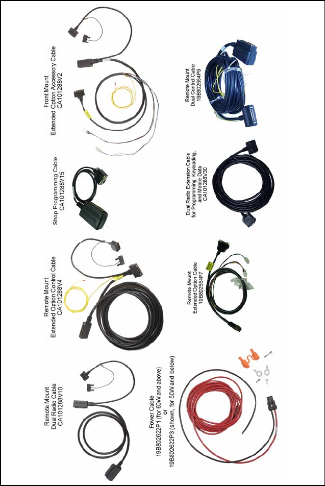
Figure 6-4: Option Cables

17
Table 6-1: M7100IP Option and Accessory Kits (60W TX and Above)
OPTION DESCRIPTION
ANTENNAS
19B209568P6 Antenna, 136-174 MHz, ¼ Wave, TNC, Roof Mount
MAHG-AN3G Antenna, 136-870 MHz, ¼ Wave, TNC, Roof Mount
REMOTE MOUNT ACCESSORIES (60W TX AND ABOVE)
MAHG-ZN5Y Includes remote mount radio front cover, front cover logo label, remote
mount accessory cable, remote mount control cable, 7.5M power
cable, microphone hanger kit, remote mount radio mounting kit, control
unit mounting kit, DB15-HD connector to control unit mounting kit, and
mobile speaker.
HAND HELD CONTROLLER (WITH SIREN) ACCESSORIES, REMOTE MOUNT
(60W TX AND ABOVE)
MAHG-ZN6C Includes Hand Held Controller (HHC) with mounting bracket, HHC
interface cable (with siren interface), remote radio front cover, front
cover logo label, remote mount accessory cable, remote mount control
cable, 7.5M power cable, remote mount radio mounting kit, mobile
speaker, and HHC operator and installation manuals.
HAND HELD CONTROLLER (WITHOUT SIREN) ACCESSORIES, REMOTE MOUNT
(60W TX AND ABOVE)
MAHG-ZN6A Includes Hand Held Controller (HHC) with mounting bracket, HHC
interface cable, remote radio front cover, front cover logo label, remote
mount accessory cable, remote mount control cable, 7.5M power
cable, remote mount radio mounting kit, mobile speaker, and HHC
operator and installation manuals.
DUAL CONTROL, SCAN CONTROL UNIT, LONG PACKAGE
MAHG-ZN6J Includes scan control unit, control unit logo label, dual control cable
(9M), accessory cable, control unit mounting kit, microphone hanger
kit, relay kits (qty 2), mobile speaker, connector support bracket, and
M7100IP operator’s manual.
DUAL CONTROL, SYSTEM CONTROL UNIT, LONG PACKAGE
MAHG-ZN6K Includes system control unit, system control unit keycap kit, control unit
logo label, dual control cable (9M), accessory cable, control unit
mounting kit, microphone hanger kit, relay kits (qty 2), mobile speaker,
connector support bracket, and M7100IP operator’s manual.
DUAL CONTROL, HHC (WITH SIREN), LONG PACKAGE
MAHG-ZN6M Includes HHC with mounting bracket, HHC interface cable (with Siren
interface), dual control cable (9M), accessory cable, relay kits (qty 2),
mobile speaker, connector support bracket, and HHC installation and
operator’s manuals.
DUAL CONTROL, HHC (WITHOUT SIREN), LONG PACKAGE
MAHG-ZN6L Includes HHC with mounting bracket, HHC interface cable, dual control
cable (9M), accessory cable, relay kits (qty 2), mobile speaker,
connector support bracket, and HHC installation and operator’s
manuals.
DUAL RADIO, HHC (WITHOUT SIREN), LONG PACKAGE
MAHG-ZN6P Includes dual radio cable, programming extension cable, 7.5M power
cable, remote radio front cover, front cover logo label, remote mount
radio mounting kit, connector support bracket, DB15-HD connector to
control unit mounting kit, and DB15-HD connector to radio mounting kit.
Refer to M/A-COM’s Products and Services Catalog for the full line of options and
accessories available for use with the M7100IP mobile radio.

18
Table 6-2: M7100IP Option and Accessory Kits (50W TX and Below)
OPTION DESCRIPTION
ANTENNAS
MAHG-AN3G Antenna, 136-870 MHz, ¼ Wave, TNC, Roof Mount, 19B209568P6
FRONT MOUNT ACCESSORIES (50W TX AND BELOW)
MAHG-ZN5W Includes front mount accessory cable assembly, 7.5M power cable,
microphone hanger kit, front mount radio mounting kit, DB15-HD
connector to radio mounting bracket kit, and mobile speaker.
REMOTE MOUNT ACCESSORIES (50W TX AND BELOW)
MAHG-ZN5X Includes remote mount radio front cover, front cover logo label, remote
mount accessory cable, remote mount control cable, 7.5M power
cable, microphone hanger kit, remote mount radio mounting kit, control
unit mounting kit, DB15-HD connector to control unit mounting kit, and
mobile speaker.
HAND HELD CONTROLLER (WITH SIREN) ACCESSORIES, REMOTE MOUNT
(50W TX AND BELOW)
MAHG-ZN6B Includes Hand Held Controller (HHC) with mounting bracket, HHC
interface cable (with siren interface), remote radio front cover, front
cover logo label, remote mount accessory cable, remote mount control
cable, 7.5M power cable, remote mount radio mounting kit, mobile
speaker, and HHC operator and installation manuals.
HAND HELD CONTROLLER (WITHOUT SIREN) ACCESSORIES, REMOTE MOUNT
(50W TX AND BELOW)
MAHG-ZN5Z Includes Hand Held Controller (HHC) with mounting bracket, HHC
interface cable, remote radio front cover, front cover logo label, remote
mount accessory cable, remote mount control cable, 7.5M power
cable, remote mount radio mounting kit, mobile speaker, and HHC
operator and installation manuals.
DUAL CONTROL, SCAN CONTROL UNIT, SHORT PACKAGE
MAHG-ZN6S Includes scan control unit, control unit logo label, dual control cable
(9M), accessory cable, control unit mounting kit, microphone hanger
kit, relay kits (qty 2), mobile speaker, connector support bracket, and
M7100IP operator’s manual.
DUAL CONTROL, SYSTEM CONTROL UNIT, SHORT PACKAGE
MAHG-ZN6T Includes system control unit, system control unit keycap kit, control unit
logo label, dual control cable (9M), accessory cable, control unit
mounting kit, microphone hanger kit, relay kits (qty 2), mobile speaker,
connector support bracket, and M7100IP operator’s manual.
DUAL CONTROL, HHC (WITH SIREN), SHORT PACKAGE
MAHG-ZN6V Includes HHC with mounting bracket, HHC interface cable (with Siren
interface), dual control cable (9M), accessory cable, relay kits (qty 2),
mobile speaker, connector support bracket, and HHC installation and
operator’s manuals.
DUAL CONTROL, HHC (WITHOUT SIREN), SHORT PACKAGE
MAHG-ZN6U Includes HHC with mounting bracket, HHC interface cable, dual control
cable (9M), accessory cable, relay kits (qty 2), mobile speaker,
connector support bracket, and HHC installation and operator’s
manuals.
DUAL RADIO, HHC (WITHOUT SIREN), SHORT PACKAGE
MAHG-ZN6N Includes dual radio cable, programming extension cable, 7.5M power
cable, remote radio front cover, front cover logo label, remote mount
radio mounting kit, connector support bracket, DB15-HD connector to
control unit mounting kit, and DB15-HD connector to radio mounting kit.
Refer to M/A-COM’s Products and Services Catalog for the full line of options and
accessories available for use with the M7100IP mobile radio.
19
7 PLANNING THE INSTALLATION
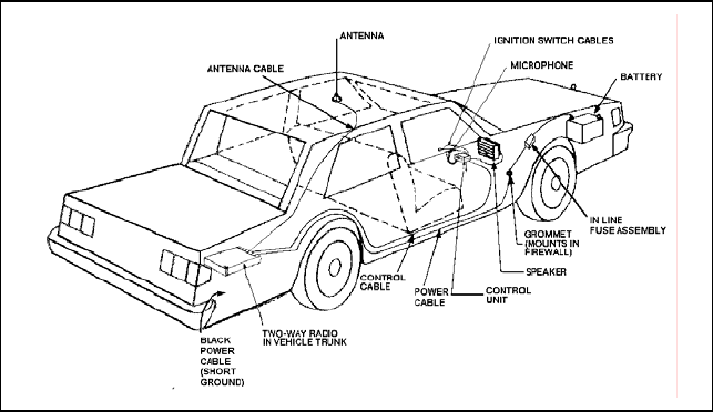
Figure 7-1 illustrates a typical single remote mount mobile radio installation.
Instructions for dual control unit and dual radio unit installations are provided
in Sections 10 and 11. Before starting any radio installation, plan the location
and positioning carefully so that it will be:
• Safe for the operator and passengers,
• Away from airbag deployment area,
• Convenient for the operator to use,
• Neat,
• Protected from water damage,
• Easy to service,
• Out of the way of auto mechanics
• Out of the way of passengers.
Figure 7-1: Typical Installation (Remote Mount Shown)
It is suggested that the radio be installed by one of the many M/A-COM
Authorized Service Centers located throughout the United States. Their
experienced service personnel can provide a proper radio installation and
make any final adjustments that may be needed.
20
CAUTION
Vehicular Electronics - Electronic fuel injection systems,
electronic anti-skid braking systems, air bags, electronic
cruise control systems, etc., are typical of the types of
electronic devices which might be prone to malfunction
due to the lack of protection from radio frequency energy
present when a radio is transmitting. If the vehicle
contains such equipment, consult the dealer to determine if
such electronic equipment will perform normally when the
radio is transmitting.
WARNING
Air Bags – For driver and passenger safety, avoid
mounting the radio above or near airbag deployment areas.
Note that vehicles might contain front driver and
passenger side airbags as well as side airbags. For
occupant safety, verify the location of all airbags before
installing radio equipment.
WARNING
For passenger safety, mount the radio securely so that the
unit will not break loose in the event of a collision. This is
especially important in station wagons, vans and similar
type installations where a loose radio could be extremely
dangerous to the vehicle occupants.

21
8 EQUIPMENT REQUIRED
The equipment required for installing the M7100IP Series Mobile Radio is
listed below:
• Crimping tool for fuse holder
• Electric drill for drilling mounting holes
• Drills and circle cutters, as follows:
¾ No. 31 (1/8-inch) drill
¾ No. 27 (9/64-inch) drill
¾ 5/8-inch drill or circle cutter
¾ 3/4-inch circle cutter, hole saw or socket punch
• Phillips and flat-blade screwdrivers
• POZIDRIV® driver
• No. 20 TORX® driver
CAUTION
Be careful to avoid damaging some vital part (fuel tank,
transmission housing, etc.) of the vehicle when drilling
mounting holes. Always check to see how far the
mounting screws will extend below the mounting surface
before installing.
CAUTION
If pilot holes must be drilled, remove all metal shavings
from drilling holes before installing screws.
22
9 INSTALLATION
9.1 RUNNING CABLES
To assure the feasibility of the planned cable routings, it is suggested that the
cables be run before mounting the radio. The M7100IP Series mobile radio
may be installed as a Front Mount or a Remote Mount. The type of mount,
the application and the options to be installed should be considered when
planning the cable runs. Figure 9-1 and Figure 9-2 provide Interconnection
Diagrams for typical installations and should be referenced throughout the
installation.
Be sure to leave some slack in each cable going to the radio so that the radio
may be pulled out for servicing with the power applied and antenna attached.
Coil any surplus cables and secure them out of the way. Try to route the
cables away from locations where they will be exposed to heat (exhaust pipes,
mufflers, tailpipes, etc.), battery acid, sharp edges or mechanical damage or
where they will be a nuisance or hazard to automobile mechanics, the driver
or passengers. Keep wiring away from electronic computer modules, other
electronic modules and ignition circuits to help prevent interference to these
components and radio equipment.
In addition, try to utilize existing holes in the firewall, trunk wall and the
channels above or beneath doors. Channels through door and window
columns that are convenient for running cables may also be used, unless rigid
or flexible conduit is to be installed for cable runs.
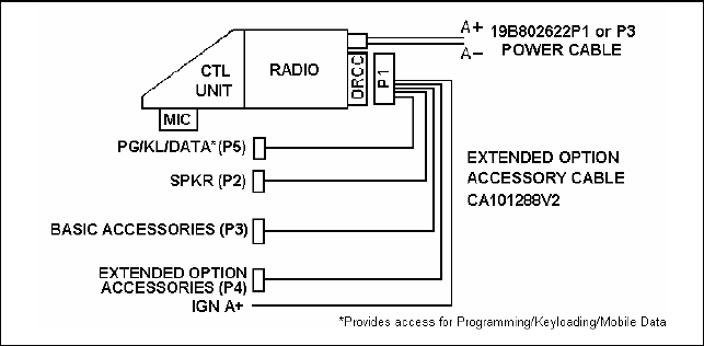
Figure 9-1: Front Mount Extended Option Accessory Interconnections
23
Figure 9-2: Remote Mount Extended Option Accessory Interconnections
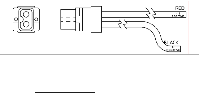
9.1.1 Power Cable
The power cable (19B802622P3 for radios 50W and below, 19B802622P1 for
radios 60W and above) consists of a red lead A+ and a black lead A-
connected to a molded 2-pin power connector and supplied with ring
terminals (refer to Figure 9-3). To install the power cable:
1. Drill a 5/8-inch hole in the firewall for the cable run and insert the rubber
grommet. Run the cable through this grommet to the battery location.
Secure the cable at several locations within the engine compartment to
prevent possible damage to cable.
2. Strip back the insulation approximately 3/8 of an inch from the end of the
black lead. Slide one of the large heat shrink sleeves onto the wire and
crimp a battery ring terminal onto this lead. Heat-shrink the sleeve over
the crimp connection. Connect the black lead directly to the ground frame
of the vehicle.
3. Cut off 12-18 inches from the red lead. Strip back the insulation
approximately 3/8 of an inch on each end of the wires. Insert the wire
ends into the small openings at the end of each fuse holder section and
crimp a fuse connector to each wire. Prepare the other end of the short
wire in the same manner as in Step 2 of this procedure and connect to the
positive (+) terminal of the battery.
NOTE
Do not install the fuse until the installation is completed
and all connections have been checked.
NOTE
Power Cable 19B802622P3 is used only with radios with
50 watts or less RF power output. 19B802622P1 is used
for radios with 60 watts or more RF power output.
24
Figure 9-3: Power Cable 19B802622P3 (50W and Below) or
19B802622P1 (60W and Above)
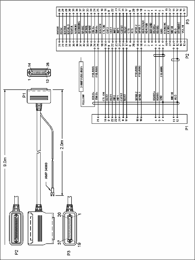
9.1.2 Accessory Cable
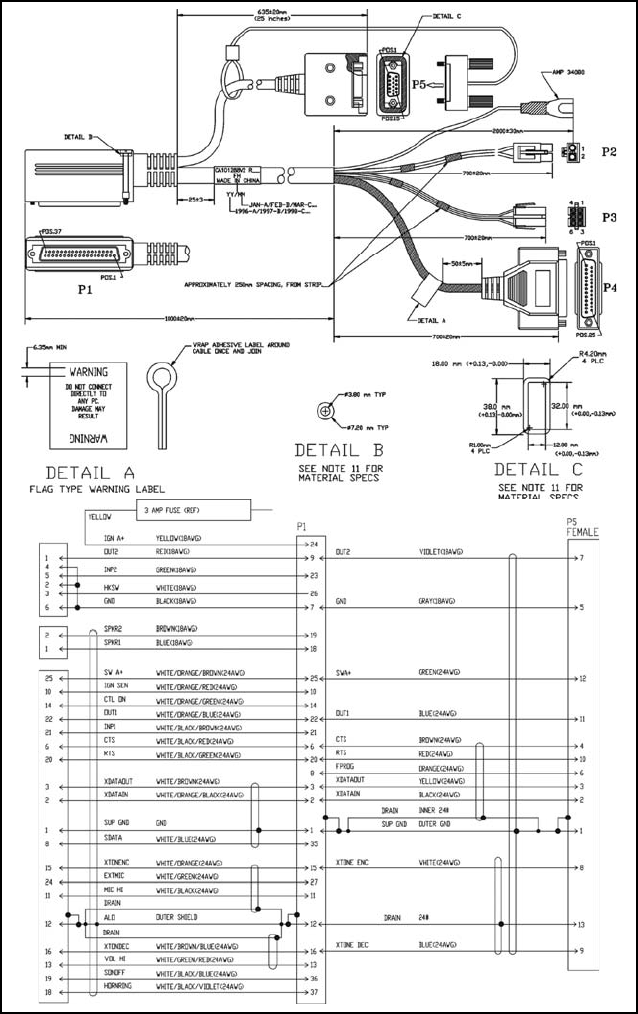
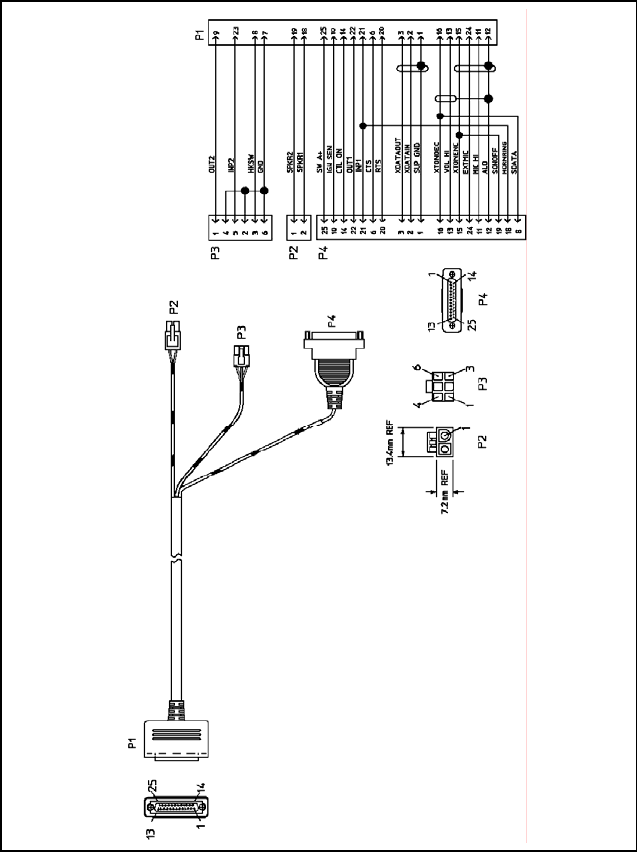
9.1.2.1 Front Mount
The Front Mount Extended Option Accessory Cable, at one end, consists of
the extended options plug (P4); basic accessories connector (P3); connection
for field programming, keyloading, and mobile data applications (P5); the
speaker connector (P2); and the ignition sense lead. At the other end is plug
P1. P1 connects to the Option/Remote Control Connector (ORCC) which is
mounted on the back of the radio (refer to Figure 9-4).
25
Figure 9-4 - Front Mount Extended Option Accessory Cable
CA101288V2
26
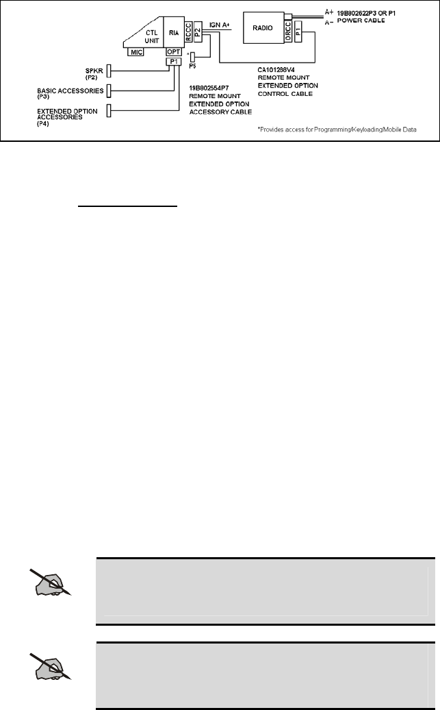
9.1.2.2 Remote Mount
The Remote Mount Extended Option Accessory Cable, at one end, consists of
the extended option plug (P4), the basic accessories connector (P3), and the
speaker connector (P2). At the other end is the plug P1. P1 will connect to
the Option Connector (OPT) which is mounted on the back of the Radio
Interface Adapter (RIA). See Figure 9-5.
Figure 9-5: Remote Mount Extended Option Accessory Cable
19B802554P7

27
9.1.3 Ignition Sense (All Applications)
NOTE
The radio, as shipped from the factory, has the "ignition
sense" feature disabled. As such, the radio will be
powered ON or OFF as determined by the front panel
ON/OFF/VOLUME control only (assuming A+ and A- are
connected). If it is desired to enable the "ignition sense"
feature, open the top cover of the radio and remove the
shield from logic PWB. Slide switch S951 from position
3-2 to 1-2. Replace shield and top cover. Be sure to apply
correct torque to screws holding top cover in place (refer
to the appropriate Maintenance Manual).
NOTE
The "Accessory" point should drop to ZERO volts when
cranking the engine and return to +12 volts after the
engine is started. If a point is chosen that drops to a
voltage between zero and +12 volts, the radio might
execute a power-up cycle several times during start up. It
is recommended that the terminal be measured with a
voltmeter to be sure it shuts off (goes to zero volts) during
the cranking of the engine.
The fuse holder must be attached to the yellow sense lead along with the ring
terminal as follows:
1. Cut the yellow sense lead approximately 6-12" from the end that will be
connected to the ignition sense point.
2. Strip the insulation from each end of the short lead and from the end of
the long lead at least 3/8".
3. Insert the stripped end of the long lead and one end of the short lead into
the narrow end of each fuse holder half.
4. Crimp the leads in the fuse holder halves with a crimping tool.
5. Insert the 3-amp fuse into one end of the fuse holder and join the two fuse
holder halves firmly together.
6. Attach the ring terminal to the end of the short lead and connect this lead
to the ignition "ON" sense point [preferably an "Accessory" point (in the
vehicle fuse panel) that is switched on when the vehicle ignition switch is
in the ACCESSORY and RUN positions].

28
CAUTION
Certain problems might be encountered when accessory
equipment is connected to the ignition or accessory lines
of the vehicle, where these lines can have large filter
capacitors and a leakage path present. If the radio does
not turn off within a reasonable amount of time after the
ignition is turned off, first try a different accessory or
ignition sense pick-up point in the vehicle. Many vehicles
have more than one circuit that is switched by the ignition
switch, and one might be available that does not have
large filter capacitors or a leakage path present.
If a different pick-up point cannot be found, add a 470-
ohm, 1-watt resistor from the ignition sense pick-up point
to ground. This will discharge the capacitor(s) or reduce
the leakage voltage to a low value. Current drain through
this resistor will be minimal (less than 0.03A) when the
ignition is switched on.
9.1.4 Control Cable (Remote Mount Only)
The Control Cable is used to connect the Control Unit (through the RIA) to
the Radio Transceiver in remote applications. Plug P2, at one end, connects
to the Remote Control Cable Connector (RCCC) mounted on the back of the
RIA. The Ignition Sense wire is also part of P2. The connection, P5, is
available for field programming, keyloading, or mobile data applications. The
other end of the Control Cable (P1) connects to the ORCC mounted on the
back of the radio. See Figure 9-6.
29
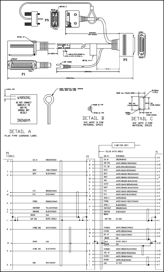
Figure 9-6: Remote Extended Option Control Cable (CA101288V4)
30
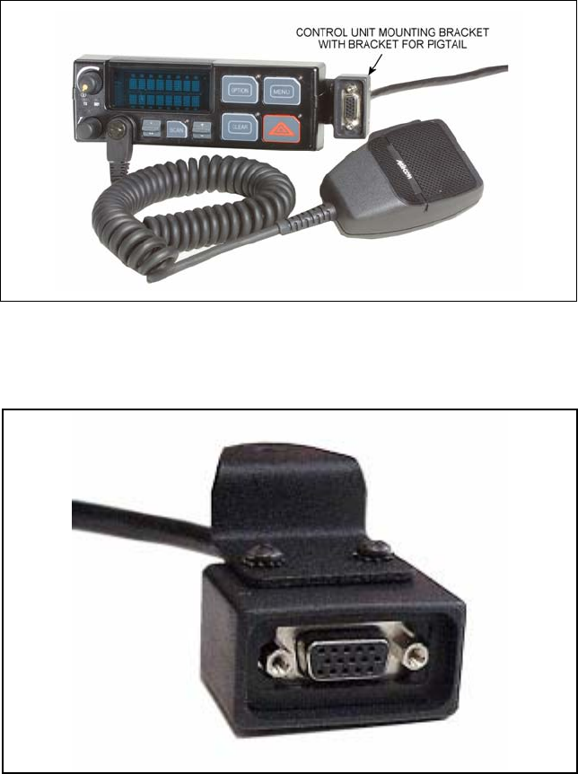
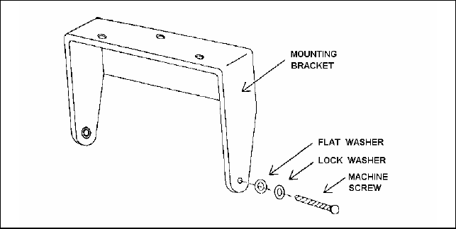
Figure 9-7: Control Unit Mounting Bracket Installation
9.2 CONTROL UNIT MOUNTING
(Remote Applications Only)
1. Using the bracket as a template, mark and drill the mounting holes. Be
sure to leave enough room at the rear of the control unit for the cable
connector and to allow the unit to swivel. Refer to Figure 9-7 for control
unit mounting bracket installation.
2. Secure the mounting bracket using the four No. 10 x 3/4 self-tapping
screws supplied (use No. 10 x 1-1/2 if needed.).
3. Secure the control unit to the bracket with the two ¼ - 20 x ½ hex head
screws and lock washers provided.
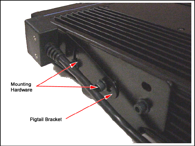
9.3 PIGTAIL BRACKET
The Pigtail Bracket is used to mount the DB15 connector for easier user
access. The DB15 connector is used to make radio programming and
keyloading by the customer easier, eliminating the need to dismantle the radio
or Control Unit. There are two Pigtail brackets: one for use with the Control
Unit and one for use with the radio mounting bracket. The following sections
include procedures to mount the Pigtail brackets in each of these
configurations.
9.3.1 Pigtail Bracket – Control Unit Mounting
For Control Unit mounting, the pigtail bracket is attached to the side of the
Control Unit bracket using existing mounting bracket hardware. The Pigtail
Bracket can be mounted to either the right or the left side of the Control Unit.
Hardware Kit, KT101533V6, contains Pigtail mounting bracket and hardware
required to attach Pigtail to bracket.
31
Figure 9-8: Control Unit Mounting Bracket with Pigtail Bracket
1. Attach DB15 connector to the rectangular end of bracket with 2 pan head
machine screws and washers. See Figure 9-9.
Figure 9-9: DB15 Connector Mounted on Control Unit Pigtail Bracket
2. Remove the ¼ - 20 x ½ hex head screw and washer from the side of the
Control Unit bracket where the Pigtail installation is desired. Retain this
hardware for Step 4.
3. Align the single hole at the end of the Pigtail Bracket with the holes in the
Control Unit bracket and the Control Unit.
4. Replace washer, insert hex head screw, and tighten. See Figure 9-10.
32
Figure 9-10: Pigtail Bracket Installed on Control Unit
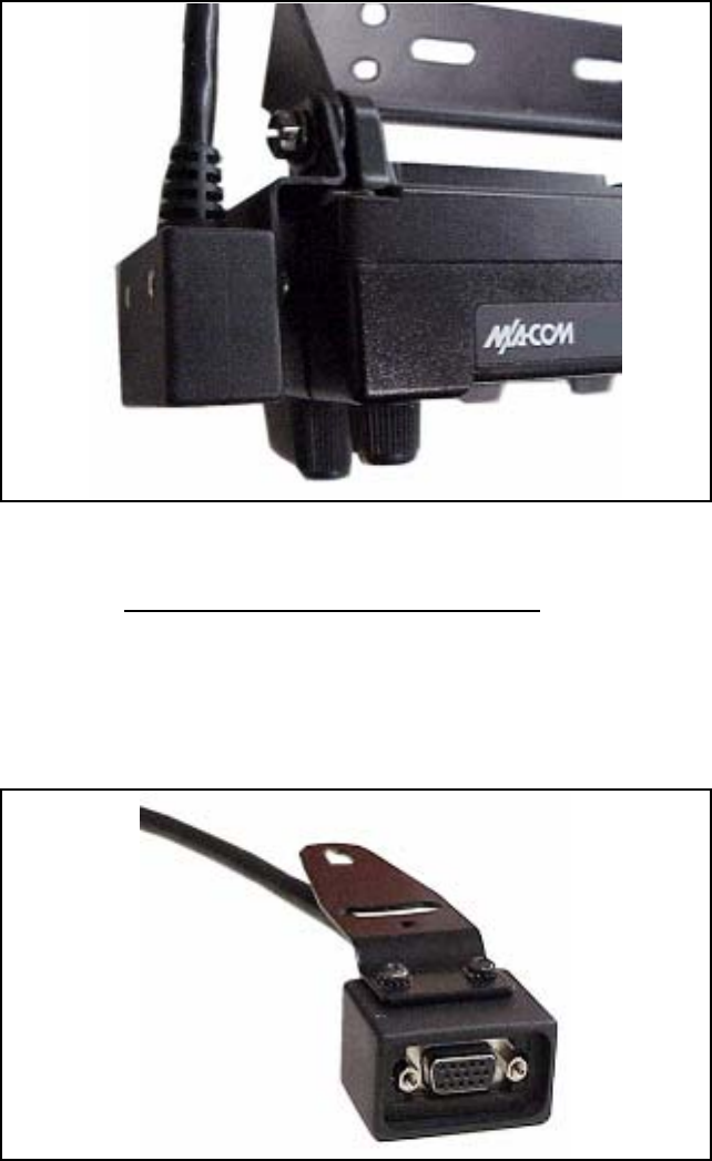
9.3.2 Pigtail Bracket – Radio Mounting
For Radio mounting, the Pigtail Bracket is attached to either side of the Radio
mounting bracket. Hardware Kit, KT101533V5, contains the Pigtail Bracket,
and hardware to attach the Pigtail to the bracket.
1. Attach DB15 connector to rectangular end of the Pigtail Bracket using 2
pan head machine screws and washers. See Figure 9-11.
Figure 9-11: DB15 Connector Mounted on Radio Pigtail Bracket
33
2. Position the Pigtail Bracket with the connector facing away from the side
and towards the front of the radio. The Pigtail Bracket can be installed on
either side of the radio.
3. Remove the first two radio mounting bracket screws and lockwashers
located closest to the front of the radio. Retain this hardware for Step 5.
4. Align the bracket hole at the smaller end of the Pigtail Bracket with the
middle hole on the radio bracket and the corresponding hole in the radio
chassis. Insert an M5 x 10mm hex head screw and lockwasher.
5. The other slot in the Pigtail Bracket will enable flexible positioning of the
pigtail. Position the bracket, and insert the remaining M5 x 10mm hex
head screw and lockwasher. Tighten both of the hex head screws to 7 N-
m (61 in-lb) to maintain the desired Pigtail position. See Figure 9-12.
Figure 9-12: Pigtail Bracket Mounted on Radio
9.4 SPEAKER
The speaker kit includes the speaker, mounting bracket and connecting cable.
Position the speaker toward the operator but follow the guidelines presented
on pages 4 through 12 to assure it does not present a hazard in the event of an
accident. The speaker may be mounted on the lower edge of the instrument
panel, the firewall or above the windshield in some trucks.
34
1. Use the mounting bracket as a template for locating the mounting holes
and mount the speaker as shown in Figure 9-13.
2. Refer to the applicable installation procedures for connection of the
speaker to the accessory cable.
Figure 9-13: Speaker Mounting Bracket
9.5 MICROPHONE HANGER AND/OR HOOKSWITCH
MOUNTING
The microphone hanger or hookswitch should be mounted in a location
convenient to the operator where it will not interfere with the safe operation of
the vehicle or be a hazard to the vehicle passengers. The hanger and
hookswitch are designed to be mounted with the open end of the mounting
button slot pointed upward. Use the hanger or hookswitch as a template to
mark and drill the mounting holes. Mount the hanger or hookswitch with the
self-tapping screws provided.
9.6 SIREN AND LIGHT
For instructions about installing the Federal Signal Corporation Siren and
Light Kit, refer to the Federal Signal Corporation Installation Instructions
(Federal Systems part number 255287B, rev. B or higher).
Program the radio to work with the Federal Systems Siren and Light Kit,
using the instructions outlined in the ProGrammer On-Line Help.
In a remote mount installation, three jumpers must be reconfigured in the
remote control unit. These jumpers are located on the Remote Interface
Adapter (RIA), a PC board in the back half of the unit. To access these
jumpers, the RIA must be removed from the control unit as follows:

35
1. Disassemble the Control Unit using steps given in LBI-39175.
2. Flex circuit PC2 does not need to be disengaged from J2, providing care
is taken to avoid excessive bending.
3. Reconfigure jumper A/B to center/B, jumper C/D to center/D, and jumper
E/F to center/F.
4. Carefully reassemble the RIA to front control panel, making sure that
there is adequate alignment and lubricant for the black o-ring gasket at
the mechanical interface between the RIA and the control panel. This
maintains the moisture seal of the control panel.
NOTE: The following issues have been reported on some M7100IP
Siren/Light installations using the Federal Signal Corporation Siren and Light
Kit:
• Occasional false activation of siren and light functions when the ignition
is turned to the “on” position and/or when the vehicle is started.
• Occasional failure to enable siren or light functions via control head,
which can be temporarily resolved by either power cycling the radio or
turning the car ignition “off” and then “on” again.
To resolve these issues above, modify the Federal Systems control cable as
follows:
1. Remove the outer shell from the DB25 side of the Federal Systems
control cable.
2. Add a jumper from pin 1 to pin 19.
This modification to the SS2000 cable harness will disable the M7100IP’s
capability to turn on and off the SS2000 from the front of the control head.
The SS2000 will now be turned on and off strictly by its own ignition switch
trigger line (red wire from 12 pin Molex® connector on SS2000 siren box).
Follow the SS2000 Federal Signal Corporation installation instructions to
attach the red ignition line correctly.
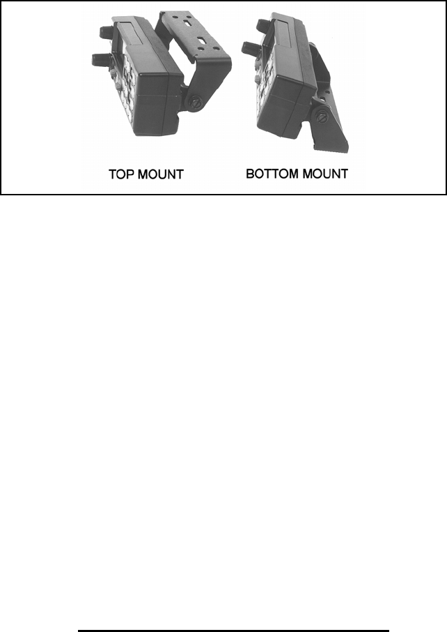
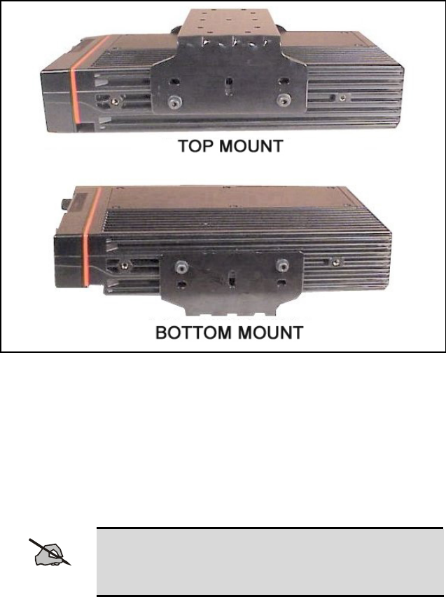
9.7 RADIO MOUNTING AND FINAL HOOK-UP
9.7.1 Front Mount
Typically, the bracket shown in Figure 9-14 is used for Front Mount
applications. The bracket can be mounted so that it is either above or below
the radio for the user's convenience. The bracket pictured in Figure 9-7 can
also be used for Remote Mount applications. The following instructions are
for a Front Mount installation using the bracket shown in Figure 9-14.
1. Use the supplied mounting bracket as a template to locate the position for
each of the drill holes. Be sure to leave enough room at the front and rear
of the radio for cable connections. Drill No. 27 (9/64) pilot holes.
36
2. Mount bracket with four 1/4"-14 x 3/4" sheet metal screws (use 1/4"-14 x
1-1/2" screws if needed).
3. Place radio into mounting bracket and secure with the M5 x 10 mm hex
head screws and M5 lock washers supplied using a No. 20 Torx driver.
4. Connect antenna coaxial cable to antenna connector (TNC).
5. Connect front mount accessory cable connector P1 to the Option/Remote
Control Connector (ORCC) and secure with the two captive screws in the
connector to the radio.
Figure 9-14: Mounting Bracket Installation (110W VHF Shown)
6. Connect front mount accessory cable connector P2 to speaker cable
connector.
7. Connect power cable to power connector on rear of radio unit and secure
with the two captive screws to the radio unit.
8. Connect the microphone connector to the connector on the front panel
and secure with the captive screw.
NOTE
Do not torque the microphone connector screw greater
than 2 in-lb. Alternatively, “finger tight plus 1/4 turn” is
acceptable.
37
9. If there are no other accessory connections, tie back plug P3 to main
cable.
10. Recheck all connections before inserting fuse into transmit fuse assembly.
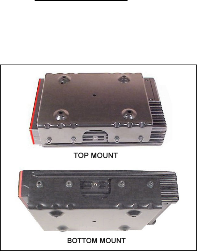
9.7.2 Remote Mount Installation
The bracket shown in Figure 9-15 is used with the 110W VHF M7100IP in
Remote Mount configurations. (The 110W VHF radio is not available in
Front Mount configurations.) The bracket shown in Figure 9-14 can be used
for Remote Mount as well as Front Mount configurations for the 800 MHz,
UHF-H, and UHF-L M7100IP radios. The following instructions are for
Remote Mount installations using the bracket shown in Figure 9-15.
Figure 9-15: Remote Mounting Bracket Installation (110W VHF Shown)
1. Using the bracket as a template, mark and drill the mounting holes using
a No. 27 drill. Be sure to leave enough room at the rear of the radio unit
for the cable connections.
38
2. Secure the mounting bracket using four 1/4"-14 x 3/4" sheet metal screws
(use 1/4"-14 x 1" if needed.) The bracket can be mounted so that it is
either above or below the radio for the user's convenience.
3. Slide the radio unit into the bracket by aligning bracket guides with
grooves on each side of radio (rear of radio should be inserted first).
Slide radio back until screw holes in front of bracket align with screw
holes in side of radio. See Figure 9-15.
4. Secure radio to the bracket with two M5 x 10 mm socket head screws
provided (7 N-m or 61 in-lb).
5. Connect antenna coaxial cable to antenna connector (TNC).
6. Connect remote control cable connector P1 to the ORCC connector on
the radio unit and secure with the two captive screws.
7. Connect other end of remote control cable to the remote control cable
connector (RCCC) on the remote control unit.
8. Connect remote mount accessory cable connector P1 to the option
connector (OPT) on control unit. Then connect the speaker to connector
P2 and accessory connector P3 to any options (hookswitch, etc.). If
connector P3 is not used, insulate and tie back to main cable.
9. Recheck all connections and cables. Insert fuse into transmit fuse
assembly.
39
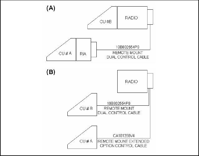
10 DUAL CONTROL UNIT INSTALLATION
Dual Control units can be configured for either front mount or remote mount
radio units. Each configuration provides for a Main Control Unit and an
Auxiliary Control Unit. In the front mount dual control unit configuration, the
Main Control Unit is on the Radio Unit itself, with the Auxiliary Control Unit
located separately in a convenient location (see Figure 10-1A). In the remote
mount dual control unit configuration, the Main Control Unit is typically
located in the vehicle cab, with the Auxiliary Control Unit located separately
in a convenient location (see Figure 10-1B).
All radio units and control units in the Dual Control configuration MUST BE
PROGRAMMED prior to final installation. It is recommended that the units
be first programmed at an Authorized Service Center, and then transferred to
the user’s installation.
Figure 10-1: Dual Control Unit – Basic Configurations for
Front Mount (A) and Remote Mount (B) Installations
40
10.1 PRE-INSTALLATION PROGRAMMING
PROCEDURE WITH PROGRAMMER - FRONT
MOUNT
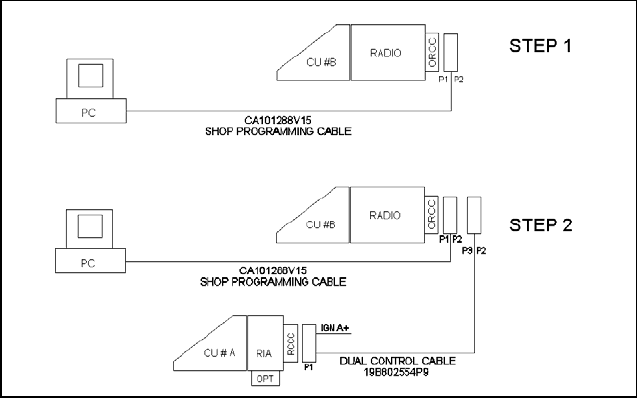
The Radio and Control Units must be programmed in a sequential procedure
to provide each Control Unit with the proper identification code.
Figure 10-2: M7100IP Dual Control Unit PC Programming Configuration
1. Connect the M7100IP Front Mount Radio with ProGrammer, as shown in
Figure 10-2, Step 1. Program the radio with the following control
configurations:
NETWORK OPTIONS
Dual Control Setup
Dual Control Enable
Audio Mode Active
Switching Mode Independent
Siren Light Controller Unit A
Siren Light Connection Unit A
Speaker Disable
Multiple Radio Setup
Multiple Radio Disable
41
INITIATE PROGRAMMING
Mobile Programming Options Push Button
Write System Keypad File Enable (System control unit)
or
Write Scan Keypad File Enable (Scan control unit)
or
Write Hand Held Controller Enable (Hand Held Controller unit)
Keypad File
CU ID (CU B) Must be Control Unit B
Personality Name <USERPERS> User’s personality
file
Radio Code J2R01A01 (or latest radio code
file)
DSP Code <SAME>
Radio Unit ID <SAME>
Keypad File <CUBMAP> Keypad definition for
Control Unit B
2. Connect the Front Mount Radio and the Auxiliary Control Unit together
with ProGrammer, as shown in Figure 10-2, Step 2. Program this
configuration with the following files:
NETWORK OPTIONS
Dual Control Setup
Dual Control Enable
Audio Mode Active
Switching Mode Independent
Siren Light Controller Unit A
Siren Light Connection Unit A
Speaker Disable
Multiple Radio Setup
Multiple Radio Disable
42
INITIATE PROGRAMMING
Mobile Programming Options Pushbutton
Write System Keypad File Enable (System control unit)
or
Write Scan Keypad File Enable (Scan control unit)
or
Write Hand Held Controller Enable (Hand Held Controller unit)
Keypad File
CU ID (CU A) Must be Control Unit A
Personality Name <USERPERS>
User’s personality file
Radio Code <SAME>
DSP Code <SAME>
Radio ID <SAME>
Keypad Files <CUAMAP> Keypad definition for
Control Unit A
Note that the Main Control Unit has ID “B” and the Auxiliary Control Unit
has ID “A” in this configuration.
10.2 PRE-INSTALLATION PROGRAMMING
PROCEDURE WITH PROGRAMMER - REMOTE
MOUNT
The Radio and Control Units must be programmed in a sequential procedure,
in order to provide each Control Unit with the proper identification code.
43
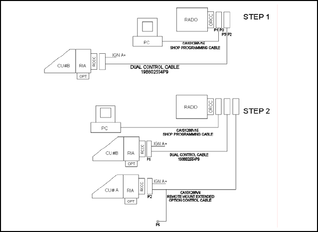
Figure 10-3: M7100IP Dual Control Unit PC Programming Configuration
Remote Mount
1. Connect the M7100IP Remote Mount Radio with ProGrammer, as shown
in Figure 10-3, STEP 1. Program the radio with the following control
configurations:
NETWORK OPTIONS
Dual Control Setup
Dual Control Enable
Audio Mode Active
Switching Mode Independent
Siren Light Controller Unit A
Siren Light Connection Unit A
Speaker Disable
Multiple Radio Setup
Multiple Radio Disable
44
INITIATE PROGRAMMING
Mobile Programming Options Push Button
Write System Keypad File Enable (System control unit)
or
Write Scan Keypad File Enable (Scan control unit)
or
Write Hand Held Controller Enable (Hand Held Controller unit)
Keypad File
CU ID (CU B) Must be Control Unit B
Personality name <USERPERS> User’s personality file
Radio Code OGXXXXX J2R01A01 (or latest radio code
file)
DSP Code <SAME>
Radio Unit ID <SAME>
Keypad File <CUBMAP> Keypad definition for
Control Unit B
2. Connect the Remote Mount Radio and the Auxiliary Control Unit
together with ProGrammer, as shown in Figure 10-3, STEP 2. Program
this configuration with the following files:
NETWORK OPTIONS
Dual Control Setup
Dual Control Enable
Audio Mode Active
Switching Mode Independent
Siren Light Controller Unit A
Siren Light Connection Unit A
Speaker Disable
Multiple Radio Setup
Multiple Radio Disable
45
INITIATE PROGRAMMING
Mobile Programming Options Push Button
Write System Keypad File Enable (System control unit)
or
Write Scan Keypad File Enable (Scan control unit)
or
Write Hand Held Controller Enable (Hand Held Controller unit)
Keypad File
CU ID (CU A) Must be Control Unit A
Personality Name <USERPERS> User’s personality
file
Radio Code <SAME>
DSP Code <SAME>
Radio ID <SAME>
Keypad File <CUAMAP> Keypad definition for
Control Unit A
Note that the Main Control Unit has ID “A” and Auxiliary Control Unit has
ID “B” in this configuration.
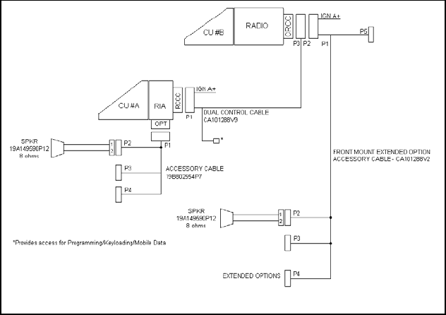
10.3 INSTALLATION INSTRUCTIONS FOR FRONT
MOUNT DUAL CONTROL UNITS
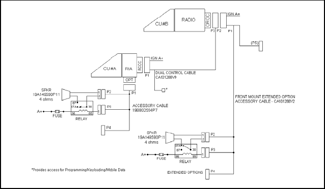
Figure 10-4: M7100IP Dual Control Unit Front Mount/Remote Mount
Installation Configuration

46
The Dual Control Unit feature is configured such that only one control unit
can be used for Extended Option accessories. All Extended Option functions
are only available at the Main Control Unit.
1. Referring to Figure 10-4, run the Dual Control Cable (19B802554P9)
between locations for the Radio Unit and Auxiliary Control Unit. Be sure
to locate the P2/P3 connector assembly at the Radio Unit.
2. After installing Radio Unit mounting hardware in the normal fashion,
connect the Dual Control Cable connector (P3) to the Radio Unit. Tighten
the two jackscrews on P3. Next, connect the Accessory Cable
(CA101288V2) Connector (P1) to the Dual Control Cable Connector
(P2), and tighten the jackscrews on P2. Connect the power cable, and
install Radio Unit in mounting bracket.
3. After installing the Auxiliary Control Unit in the normal fashion, connect
the Dual Control Cable (P1) to Auxiliary Control Unit, and tighten
jackscrews.
4. Connect the Remote Mount Accessory Cable (19B802554P7) to the
Auxiliary Control Unit.
5. A yellow Ignition Sense lead is provided on the Dual Control Cable and
the Front Mount Accessory Cable. If the “Ignition Sense” feature is
enabled on the Radio Unit, it is necessary to connect only one of the
yellow leads provided, whichever is convenient. Tape back the unused
yellow lead (see Page 27 for details).
6. Install the Speakers in convenient locations near the Radio Unit and
Auxiliary Control Unit.
Parallel Audio Installation Requirements
In special configurations that require both speakers to operate at the same
time (simultaneous audio), install the speakers for parallel audio operation.
Refer to Figure 10-5 for the Parallel Audio Setup Installation. Perform the
following steps to install parallel audio speakers:
A. Use the two 8Ω speakers, part number 19A149590P12, in place of
the two 4Ω speakers, part number LS102824V1.
B. Hardwire each speaker directly (without relays) as shown in
Figure 10-4.
NOTE
It is very important to use the correct speakers for this application.
Wiring 4Ω speakers in this configuration can cause damage to the
radio.
47
Figure 10-5: M7100IP Dual Control Unit Front Mount/Remote Mount
Installation Configuration – Parallel Audio
7. Install a relay (19A149299P1), from the kits supplied, at a location near
the leads from each speaker. For mounting, use the #8x3/4” sheet metal
screw and nut plate supplied with each kit.
8. At a convenient point cut one of the wires in each of the 2-wire speaker
cables, spread the leads, and strip the ends. Crimp a 1/4” tab receptacle to
each end.
9. Radio Unit Speaker: Connect the lead nearest the speaker to Pin 87A of
the relay. Connect the lead nearest the connector to Pin 30 of the relay.
Connect the connector to the Accessory Cable P2 (refer to Figure 10-4).
10. Auxiliary Control Unit Speaker: Connect the lead nearest the speaker to
Pin 87 of the relay. Connect the lead nearest the connector to Pin 30 of
the relay. Connect the connector to the Accessory Cable P2 (refer to
Figure 10-4).
11. For each relay: Connect a #18 AWG black wire between the relay, Pin
85 and Accessory Cable P3-1 (labeled “OUT2” on the schematic
diagrams in the service manual). Use a 1/4” tab receptacle on the relay
side and mating Molex connector and pins on the accessory cable side.
Connect the mating Molex connector to the Accessory Cable P3 when
finished (refer to Figure 10-4).
48
12. For each relay: Connect a #18 AWG red wire to the relay, Pin 86. Cut to
length, and connect to the 1A fuse holder (supplied). Use crimp on
connectors supplied. Connect the other side of the 1 amp fuse holder to
A+ battery source or vehicle A+ fuse block. Use #18 AWG red wire and
ring lug supplied, if needed (see Figure 10-4).
13. Check dual control operation, using operator’s manual as a test guide. In
ProGrammer, make sure the “DUAL CONTROL SPEAKER” is
programmed ACTIVE LOW.
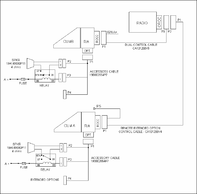
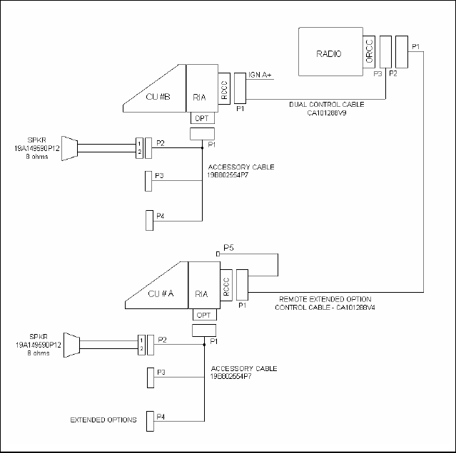
10.4 INSTALLATION INSTRUCTIONS FOR REMOTE
MOUNT DUAL CONTROL UNITS
Figure 10-6: M7100IP Dual Control Unit Remote Mount/Remote Mount
Installation Configuration
1. Referring to Figure 10-6, run the Remote Control Cable (CA101288V4)
between locations for the Radio Unit and Main Control Unit.

49
2. Run the Dual Control Cable (19B802554P9) between locations for the
Radio Unit and Auxiliary Control Unit. Be sure to locate the P2/P3
connector assembly at the radio unit.
3. After installing the Radio Unit in the normal fashion, connect the dual
control cable connector (P3) to the Radio Unit. Tighten the two
jackscrews on P3. Next, connect the Remote Control Cable connector
(P1) to the Dual Control Cable connector (P2), and tighten jackscrews on
P2.
4. After installing the Main Control Unit in the normal fashion, connect the
Remote Control Cable (P2) to the Main Control Unit, and tighten
jackscrews.
5. After installing the auxiliary control unit in the normal fashion, connect
the Dual Control Cable (P1) to the Auxiliary Control Unit, and tighten
jackscrews.
6. Connect the Remote Mount Extended Option Accessory Cable
(19B802554P7) to the Auxiliary Control Unit and the Main Control Unit.
Please note: All extended option functions are only available at the
Main Control Unit.
7. A yellow ignition sense lead is provided on each control cable. If the
“Ignition Sense” feature is enabled on the Radio Unit, it is necessary to
connect only one of the yellow leads provided, whichever is convenient.
Tape back the unused yellow lead. See page 27 for details.
8. Install the speakers in convenient locations near each control unit.
Parallel Audio Installation Requirements
In special configurations that require both speakers to operate at the same
time (simultaneous audio), install the speakers for parallel audio operation.
Refer to Figure 10-8 for the Parallel Audio Setup Installation. Perform the
following steps to install parallel audio speakers:
A. Use the two 8Ω speakers, part number 19A149590P12, in place of the
two 4Ω speakers, part number LS102824V1.
B. Hardwire each speaker directly (without relays) as shown in Figure
10-6.
NOTE
It is very important to use the correct speakers for this application,
wiring 4Ω speakers in this configuration may cause damage to the
radio.
50
9. Install a relay (19A149299P1) from the kits supplied at a location near
the leads from each speaker. For mounting, use the #8 X 3/4” sheet metal
screw and nut plate supplied with each kit.
Figure 10-7: M7100IP Dual Control Unit Remote/Remote Mount
Installation Configuration – Parallel Audio
10. At a convenient point cut one of the wires in each of the 2-wire speaker
cables, spread the leads, and strip the ends. Crimp a 1/4” tab receptacle to
each end.
11. Main Control Unit Speaker: Connect the lead nearest the speaker to Pin
87 of the relay. Connect the lead nearest the connector to Pin 30 of the
relay. Connect connector to the accessory cable P2 (refer to Figure 10-7).
12. Auxiliary Control Unit Speaker: Connect the lead nearest the speaker to
Pin 87A of the relay. Connect the lead nearest the connector to Pin 30 of
the relay. Connect the connector to accessory cable P2 (refer to Figure
10-7).

51
13. For Each Relay: Connect a #18 AWG black wire between the relay, Pin
85 and accessory cable P3-1 (labeled “OUT2” on schematic diagrams in
the maintenance manual). Use a 1/4” tab receptacle on the relay side and
a mating Molex connector and pins on the accessory cable side. Connect
the mating Molex connector to the accessory cable P3 when finished
(refer to Figure 10-7).
14. For Each Relay: Connect one end of a #18 AWG red wire to the relay,
Pin 86. Cut the lead to length, and connect the other end to the 1 amp fuse
holder supplied. Use crimp on connectors supplied. Connect the other
side of the 1 amp fuse holder to the A+ battery source or a vehicle A+
fuse block. Use a #18 AWG red wire and a ring lug supplied, if needed
(refer to Figure 10-7).
15. Check dual control operation, using the operator’s manual as a test guide.
In ProGrammer, make sure the “DUAL CONTROL SPEAKER” is
programmed ACTIVE HIGH.
10.5 FIELD PROGRAMMING WITH PROGRAMMER –
DUAL CONTROL UNITS
Once installed, the M7100IP can be programmed through connector P5 on
cable assemblies, CA101288V2, V4, and V10. (Note: Cable CA101288V10
is only used with Dual Radio configurations.)
Please note: Keyloading and Mobile Data functions are also available through
the P5 connector on the cable assemblies mentioned above. Please follow the
applicable instructions in the appropriate manuals for these applications.
Perform the following procedure for each installation configuration:
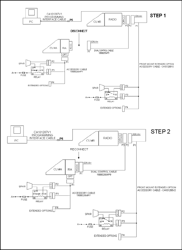
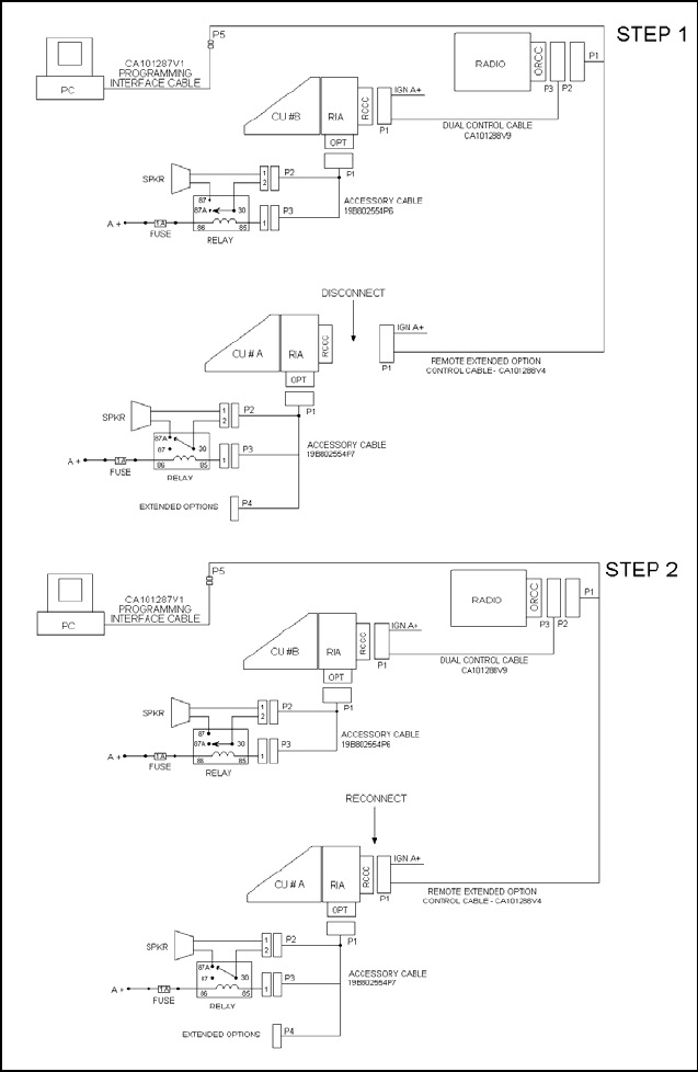
10.5.1 Field Programming Procedure - Dual Control
Units – Front/Remote Mount Configuration
The Radio and Control Units must be programmed in a sequential procedure
in order to provide each Control Unit with the proper identification code.
1. Connect the M7100IP Front Mount Radio and the Auxiliary Control Unit
per the ProGrammer setup as shown in Figure 10-8, STEP 1 with Control
Unit A disconnected. Program the radio with the control configurations
shown in Step 1 of “Pre-Installation Programming Procedure with
ProGrammer – Front Mount” and adjust as necessary for the specific
application.
2. Connect the Front Mount Radio and Auxiliary Control Unit per
ProGrammer setup as shown in Figure 10-8, STEP 2 with Control Unit A
reconnected. Program the configurations shown in Step 2 of “Pre-
Installation Programming Procedure with ProGrammer – Front Mount”
and adjust as necessary for the specific application.
52
Figure 10-8: M7100IP Field Programming – Dual Control Unit
Front/Remote Mount Configuration

53
10.5.2 Field Programming Procedure - Dual Control
Units – Remote/Remote Mount Configuration
The Radio and Control Units must be programmed in a sequential procedure
in order to provide each Control Unit with the proper identification code.
1. Configure the M7100IP Remote Mount Radio per ProGrammer setup as
shown in Figure 10-9, Step 1 with Control Unit #A disconnected.
Program the radio with the control configurations shown in STEP 1 of
“Pre-Installation Programming Procedure with ProGrammer – Remote
Mount” and adjust as necessary for the specific application.
2. Now configure the Remote Mount Radio and Auxiliary Control Unit per
ProGrammer setup as shown in Figure 10-9, STEP 2, with Control Unit
#A. Program the configurations shown in Step 2 of “Pre-Installation
Programming Procedure with ProGrammer – Remote Mount” and adjust
as necessary for the specific application.
54
Figure 10-9: M7100IP Field Programming – Dual Control Unit
Remote/Remote Mount Configuration
55
Figure 10-10: Remote Mount Dual Control Cable 19B802554P9
56
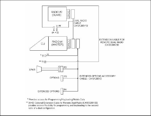
11 DUAL RADIO UNITS
The Dual Radio feature can be configured for two remote mount radio units or
for one front mount unit and one remote mount unit. In remote mount
configurations the Control Unit is typically located in the vehicle cab, with the
Radio Units located side-by-side in vehicle trunk. In front/remote mount
configurations the front mount unit is located in the vehicle cab, with the
remote mount unit located in a convenient location nearby. The
remote/remote mount configuration is the preferred installation, since a
separate control unit is required to program the remote unit in a front/remote
mount configuration.
The following Dual Radio Unit configurations are not allowed:
• Any configuration using a DIN cassette mount.
• Any installation where Extended Options are required from both Radio
Units. Extended options are supported in one Radio Unit only.
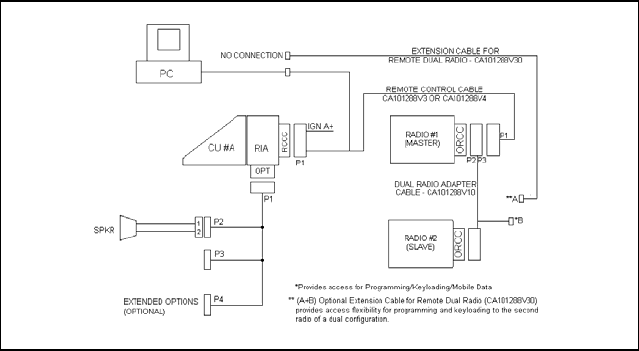
11.1 PRE-INSTALLATION PROGRAMMING
PROCEDURE WITH PROGRAMMER – DUAL
RADIO UNITS
Both Radio Units in the Dual Radio configuration MUST BE
PROGRAMMED prior to final installation. It is recommended that the units
be first programmed at an Authorized Service Center, and then transferred to
the user's installation.
These configurations provide for a Master Radio Unit and a Slave Radio Unit.
In the remote/remote mount configuration, the Master Radio Unit is always
the radio most directly connected to the Control Unit. In the front/remote
mount configuration, the Master Radio Unit is always the front mount radio.
Extended Options are allowed only in the Master Radio Unit. Programming
each radio is straightforward, with one radio programmed as a Master radio
and one as a Slave radio.
1. Decide which Radio Unit will be the Master Unit. Configure the radio for
programming as shown in the applicable maintenance manual.
2. Program the Master Radio Unit (refer to the following programming
configuration).
a. In the “Multi-Radio” field of ProGrammer, select “Master.”
b. Select any M7100IP keypad programming options if the keypad is to be
programmed. The M7100IP keypad options can only be programmed
with “multi-radio” set to “Master” in a dual radio personality.
3. Program the unit normally. Include Extended Option features, if purchased.
57
4. Program the Slave Unit (refer to the programming configuration that
follows).
a. Connect the Slave Radio Unit for programming. Be sure to use the
programming configuration for remote mount and supply the required
control unit if for a front/remote mount dual radio configuration.
b. In the “Multi-Radio” field of ProGrammer, select “Slave.”
5. Program the unit normally. Do NOT include Extended Option features.
Both radio units are now ready for vehicular installation.
NETWORK OPTIONS
Dual Control Setup
Dual Control Disable
Speaker Disable
Multiple Radio Setup
Multiple Radio Enable
Radio Type Slave or Master
Power Up Volume 5
Mute Time-Out 30.0
Termination Enable
Master Radio Setup
Display Selected for Master radio only
Power Up Enable for Master radio only
Power Up Radio Master for Master radio only
Receive Emergency Enable for Master radio only
Received Audio Enable for Master radio only
Multiple Radio ProSound Settings
MuRPS Disable for Master radio only
58
INITIATE PROGRAMMING
Mobile Programming Options Push Button
Write System Keypad File Enable (System control unit)
or
Write Scan Keypad File Enable (Scan control unit)
or
Write Hand Held Controller Enable (Hand Held Controller unit)
Keypad File
Personality Name <USERPERS> User’s personality
file
Radio Code <SAME>
DSP Code <SAME>
Radio ID <SAME>
11.2 INSTALLATION INSTRUCTIONS FOR
FRONT/REMOTE MOUNT DUAL RADIO
CONFIGURATION
Figure 11-1: M7100IP Dual Radio Front Mount/Remote Mount
Installation Configuration
59
1. Plan the mounting locations of the two Radio Units. Note that the maximum
cable length allowed between the two radios is two meters. Run Dual Radio
Cable (CA101288V10) between locations for Master and Slave Radio Units
(refer to Figure 11-1). Be sure to locate the P2/P3 connector assembly at the
Master Radio Unit.
2. After installing Master Radio Unit mounting hardware, connect the Dual
Radio Cable Connector (P3) to the Master Radio Unit. Tighten the two
jackscrews on P3. Next, connect the Accessory Cable (CA101288V2)
Connector (P1) to the Dual Radio Cable Connector (P2), and tighten to
jackscrews on P2.
3. Connect the Microphone and Accessories. Refer to Accessory Installation
Manual for proper connection of Accessories.
4. Connect Power Cable and Antenna, then install Master Radio Unit in
mounting bracket.
5. Connect "IGN A+" lead, if option is desired. Be sure internal switch S951 is
set properly. Refer to NOTE on Page 27 of this manual for details.
6. After installing Slave Radio Unit in its mounting hardware, connect Dual
Radio Cable (P1), and tighten jackscrews. Be sure S951 setting on Slave
Radio Unit is same as for Master Radio Unit. Connect Power Cable and
Antenna to Slave Radio.
7. Check Dual Radio operation, using Operator's Manual MM102341V1 as a
guide.
60
11.3 INSTALLATION INSTRUCTIONS
REMOTE/REMOTE MOUNT DUAL RADIO
CONFIGURATION
Figure 11-2: M7100IP Dual Radio Remote Mount/Remote Mount
Installation Configuration
1. Plan the mounting locations of the two Radio Units. Note that the maximum
cable length allowed between the two radios is two meters. Referring to
Figure 11-2, run Dual Radio Cable (CA101288V10) between locations for
Master and Slave Radio Units. Be sure to locate the P2/P3 connector
assembly at the Master Radio Unit.
2. After installing Master Radio Unit mounting hardware, connect the Dual
Radio Cable Connector (P3) to the Master Radio Unit. Tighten the two
jackscrews on P3.
3. Next, route the Remote Mount Extended Option Control Cable
(CA101288V4) between the Control Head and Master Radio locations.
After installing the Control Head, connect the Remote Control Cable
Connector (P2) to the Control Head.
4. Connect "IGN A+" lead, if option is desired. Be sure internal switch S951
on the Master Radio is set properly. Refer to Page 27 of this manual for
details.
5. Connect Accessory Cable (19B802554P7) Connector (P1) to Control Head.
6. Connect the Microphone and Accessories. Refer to the Accessory
Installation Manual for proper connection of Accessories.
7. Now, connect Remote Control Cable Connector (P1) to the Dual Radio
Cable Connector (P2), and tighten to jackscrews on P2.

61
8. Connect the Power Cable and Antenna, then install the Master Radio Unit in
the mounting bracket.
9. After installing the Slave Radio Unit in its mounting hardware, connect Dual
Radio Cable (P1), and tighten the jackscrews. Be sure the S951 setting on
the Slave Radio Unit is the same as for the Master Radio Unit. Connect the
Power Cable and Antenna to the Slave Radio.
10. Check Dual Radio operation, using operator's manual MM102341V1 as a
guide.
11.4 FIELD PROGRAMMING WITH PROGRAMMER –
DUAL RADIO UNITS
Once installed, the M7100IP can be programmed through connector P5 on
cable assemblies CA101288V2, V4, and V10. Please Note: Keyloading and
Data functions are also available through the P5 connector on these cables.
Also note that extended options are supported on ONE radio unit only.
Follow the applicable instructions for extended option programming.
11.4.1 Field Programming Procedure for Front/
Remote Mount Dual Radio Configuration
The Radio and Control Units must be programmed in a sequential procedure
in order to provide each Control Unit with the proper identification code.
1. Configure the M7100IP Master Radio per the ProGrammer setup shown in
Figure 11-3, STEP 1, with the Slave Radio disconnected. Program the
Master Radio with the control configurations per the Pre-Installation
Programming Procedure with ProGrammer – Dual Radio Units and adjust
as necessary for the desired application.
2. Now configure the Slave Radio with ProGrammer as shown in Figure
11-3, STEP 2. The Master Radio should now be disconnected with the
Slave Radio connected as shown. Program the Slave Radio with the
configuration per the Pre-Installation Programming Procedure with
ProGrammer – Dual Radio Units and adjust as needed for the desired
application.
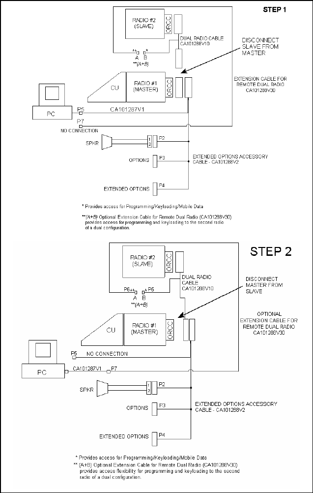
62
Figure 11-3: Dual Radio Configuration – Front/Remote Mount
PC Programming Procedure

63
11.4.2 Field Programming Procedure for Remote/
Remote Mount Dual Radio Configuration
The Radio and Control Units must be programmed in a sequential procedure
in order to provide each Control Unit with the proper identification code.
1. Connect the M7100IP Master Radio per the ProGrammer setup as shown
in Figure 11-4, STEP 1 with the Slave Radio disconnected. Program the
Master Radio with the control configurations per the Pre-Installation
Programming Procedure with ProGrammer – Dual Radio Units and adjust
as necessary for the desired application.
2. Connect the Slave Radio with ProGrammer as shown in Figure 11-4,
STEP 2. The Master Radio should now be disconnected, with the Slave
Radio connected as indicated. Program the Slave Radio with the
configuration per the Pre-Installation Programming Procedure with
ProGrammer – Dual Radio Units and adjust as necessary for the desired
application.
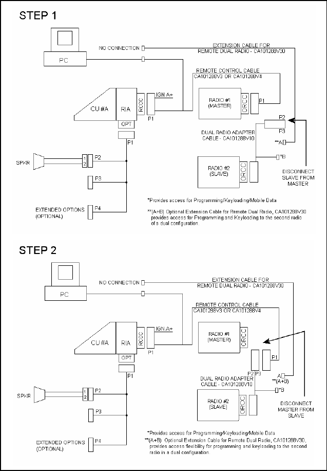
64
Figure 11-4: Dual Radio Configuration – Remote/Remote Mount
PC Programming Procedure
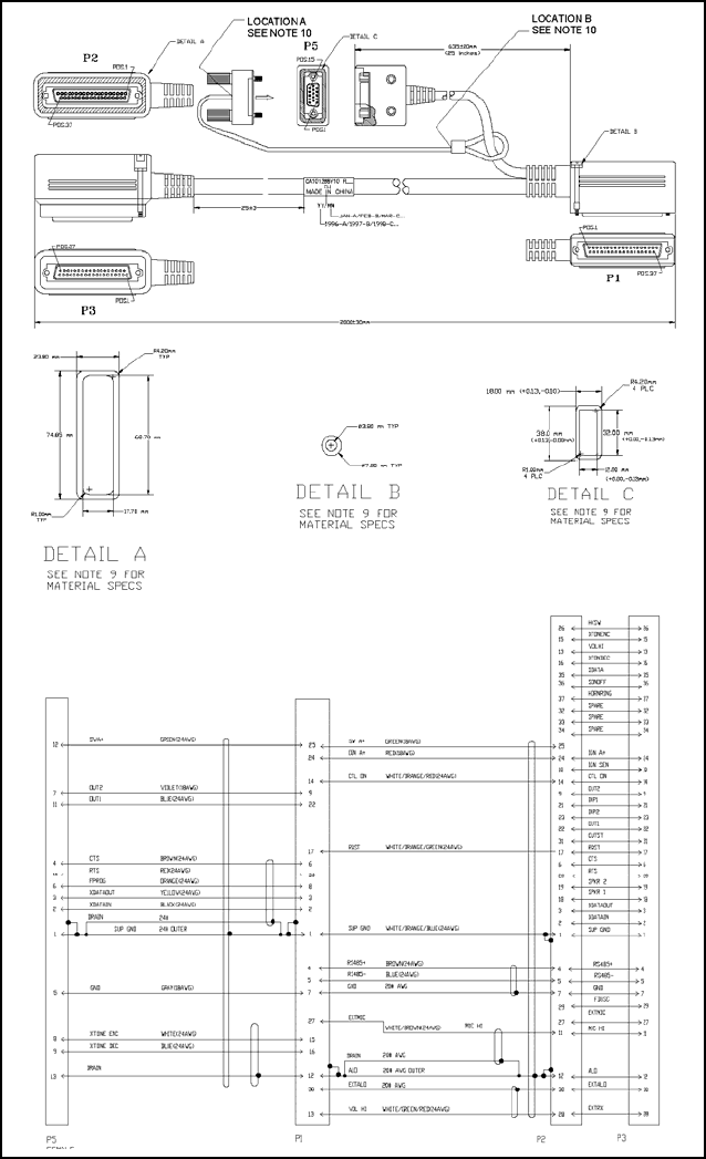
65
Figure 11-5: Dual Radio Control Cable (CA101288V10)

66
11.5 ANTENNA
Installation instructions for the antenna are packaged with the antenna. The
antenna must be installed in accordance with good engineering practice for
optimum results.
11.5.1 Typical Mobile Antenna Installation
A permanent mount-type antenna must be located in the center of the roof.
WARNING
See the Section 2 for further information regarding
Maximum Permissible Exposure (MPE) limits of RF
radiation absorption set by the FCC.
Route the antenna cable away from locations where it will be exposed to heat,
sharp edges or mechanical damage, and where it will be out of the way of the
driver, passengers or vehicles mechanics. Wherever possible, use existing
holes in the trunk wall and channels above or beneath doors and window
columns.
Avoid routing the antenna cable near any electronic modules or along side
any vehicle wiring.
Connect the antenna cable to the TNC on the radio, being careful not to twist
the cable.

67
12 WARRANTY
A. M/A-COM, Inc. (hereinafter "Seller") warrants to the original purchaser for use (hereinafter
"Buyer") that Equipment manufactured by or for the Seller shall be free from defects in
material and workmanship, and shall conform to its published specifications. With respect to
all non-M/A-COM Equipment, Seller gives no warranty, and only the warranty, if any, given
by the manufacturer shall apply. Rechargeable batteries are excluded from this warranty
but are warranted under a separate Rechargeable Battery Warranty (ECR-7048).
B. Seller’s obligations set forth in Paragraph C below shall apply only to failures to meet the
above warranties occurring within the following periods of time from date of sale to the
Buyer and are conditioned on Buyer’s giving written notice to Seller within thirty (30) days of
such occurrence:
1. for fuses and non-rechargeable batteries, operable on arrival only.
2. for parts and accessories (except as noted in B.1) sold by Seller’s Service Parts Operation,
ninety (90) days.
3. for PANTHER™ Series handportable and mobile radios, two (2) years.
4. for all other equipment of Seller’s manufacture, one (1) year.
C. If any Equipment fails to meet the foregoing warranties, Seller shall correct the failure at its
option (i) by repairing any defective or damaged part or parts thereof, (ii) by making
available at Seller’s factory any necessary repaired or replacement parts, or (iii) by replacing
the failed Equipment with equivalent new or refurbished Equipment. Any repaired or
replacement part furnished hereunder shall be warranted for the remainder of the warranty
period of the Equipment in which it is installed. Where such failure cannot be corrected by
Seller’s reasonable efforts, the parties will negotiate an equitable adjustment in price. Labor
to perform warranty service will be provided at no charge during the warranty period only for
the Equipment covered under Paragraph B.3 and B.4. To be eligible for no-charge labor,
service must be performed at a M/A-COM factory, by an Authorized Service Center (ASC)
or other Servicer approved for these purposes either at its place of business during normal
business hours, for mobile or personal equipment, or at the Buyer’s location, for fixed
location equipment. Service on fixed location equipment more than thirty (30) miles from the
Service Center or other approved Servicer’s place of business will include a charge for
transportation.
D. Seller’s obligations under Paragraph C shall not apply to any Equipment, or part thereof,
which (i) has been modified or otherwise altered other than pursuant to Seller’s written
instructions or written approval or, (ii) is normally consumed in operation or, (iii) has a
normal life inherently shorter than the warranty periods specified in Paragraph B, or (iv) is
not properly stored, installed, used, maintained or repaired, or, (v) has been subjected to
any other kind of misuse or detrimental exposure, or has been involved in an accident.
E. The preceding paragraphs set forth the exclusive remedies for claims based upon defects in
or nonconformity of the Equipment, whether the claim is in contract, warranty, tort (including
negligence), strict liability or otherwise, and however instituted. Upon the expiration of the
warranty period, all such liability shall terminate. The foregoing warranties are exclusive and
in lieu of all other warranties, whether oral, written, expressed, implied or statutory. NO
IMPLIED OR STATUTORY WARRANTIES OF MERCHANTABILITY OR FITNESS FOR
PARTICULAR PURPOSE SHALL APPLY. IN NO EVENT SHALL THE SELLER BE LIABLE
FOR ANY INCIDENTAL, CONSEQUENTIAL, SPECIAL, INDIRECT OR EXEMPLARY
DAMAGES.
This warranty applies only within the United States.
M/A-COM, Inc. M/A-COM, Inc.
1011 Pawtucket Blvd. 221 Jefferson Ridge Parkway
Lowell, MA 01853 Lynchburg, VA 24501
1-877-OPENSKY 1-800-528-7711
ECR-7047C

M/A-COM Wireless Systems
221 Jefferson Ridge Parkway
Lynchburg, Virginia 24501
(Outside USA, 434-385-2400) Toll Free 800-528-7711
www.macom-wireless.com Printed in U.S.A.