HARRIS TR-0035-E M7100 VHF Mobile, 8-50W User Manual MM21853 M7100 IP Desktop and Wall Mount Station
HARRIS CORPORATION M7100 VHF Mobile, 8-50W MM21853 M7100 IP Desktop and Wall Mount Station
HARRIS >
Contents
Manual
Operator’s Manual
MM21853
Mar-05
M7100IP
Desktop Station
Wall Mount Station

2
MANUAL REVISION HISTORY
REV DATE DESCRIPTION
- Mar. 2005 Initial release.
M/A-COM Technical Publications would particularly appreciate feedback on any errors found in
this document and suggestions on how the document could be improved. Submit your comments
and suggestions to:
Wireless Systems Business Unit or fax your comments to: (434) 455-6851
M/A-COM, Inc.
Technical Publications or e-mail us at: techpubs@tycoelectronics.com
221 Jefferson Ridge Parkway
Lynchburg, VA 24501
CREDITS
M/A-COM and EDACS are registered trademarks and PANTHER and ProGrammer are
trademarks of M/A-COM, Inc.
NOTICE!
This manual covers M/A-COM products manufactured and sold by
M/A-COM, Inc.
NOTICE!
Repairs to this equipment should be made only by an authorized service
technician or facility designated by the supplier. Any repairs, alterations or
substitution of recommended parts made by the user to this equipment not
approved by the manufacturer could void the user’s authority to operate the
equipment and the manufacturer’s warranty.
NOTICE!
The software contained in this device is copyrighted by M/A-COM, Inc.
Unpublished rights are reserved under the copyright laws of the United States.
This manual is published by M/A-COM, Inc., without any warranty. Improvements and changes
to this manual necessitated by typographical errors, inaccuracies of current information, or
improvements to programs and/or equipment, may be made by M/A-COM, Inc., at any time and
without notice. Such changes will be incorporated into new editions of this manual. No part of this
manual may be reproduced or transmitted in any form or by any means, electronic or mechanical,
including photocopying and recording, for any purpose, without the express written permission of
M/A-COM, Inc.
Copyright © 2005, M/A-COM, Inc. All rights reserved.

3
TABLE OF CONTENTS Page
1 SAFETY INFORMATION .........................................................4
2 INTRODUCTION........................................................................5
2.1 STANDARD FEATURES................................................... 5
2.2 OPTIONS............................................................................. 6
2.2.1 Remote/Intercom Option............................................... 6
2.2.2 VU Meter/Clock Option................................................ 6
2.2.3 Remote/Intercom/VU Meter/Clock Option................... 7
2.2.4 Wall Mount Station Control Panel................................ 7
3 CONTROLS AND INDICATORS ............................................. 8
3.1 VOLUME CONTROL......................................................... 8
3.2 REMOTE/INTERCOM SWITCHES................................... 8
3.3 VU METER AND CLOCK ................................................. 8
3.4 DESK MICROPHONE........................................................ 8
4 STATION OPERATION............................................................. 9
4.1 BASIC STATION................................................................ 9
4.2 REMOTE/INTERCOM ....................................................... 9
4.3 CLOCK .............................................................................. 11
4.3.1 12/24 hour mode ......................................................... 11
4.3.2 Setting the Time.......................................................... 11
4.3.3 Light Intensity............................................................. 11
4.4 TONE REMOTE CONTROLLER .................................... 12
4.5 5-FUNCTION REMOTE CONTROLLER........................ 12
4.5.1 Making a Call from a Remote Controller.................... 12
5 LOCAL/REMOTE CONTROLS SUMMARY ....................... 13
6 WARRANTY..............................................................................14
1 SAFETY INFORMATION
The following conventions are used throughout this manual to alert the user to
general safety precautions that must be observed during all phases of
operation, service, and repair of this product. Failure to comply with these
precautions or with specific warnings elsewhere in this manual violates safety
standards of design, manufacture, and intended use of the product.
M/A-COM, Inc. assumes no liability for the customer’s failure to comply with
these standards.
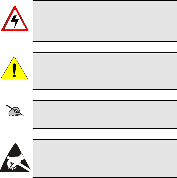
WARNING
The WARNING symbol calls attention to a procedure,
practice, or the like, which, if not correctly performed or
adhered to, could result in personal injury. Do not proceed
beyond a WARNING symbol until the conditions identified
are fully understood or met.
CAUTION
The CAUTION symbol calls attention to an operating
procedure, practice, or the like, which, if not performed
correctly or adhered to, could result in damage to the
equipment or severely degrade the equipment performance.
NOTE
The NOTE symbol calls attention to supplemental
information, which may improve system performance or
clarify a process or procedure.
The ESD symbol calls attention to procedures, practices, or
the like, which could expose equipment to the effects of
Electro-Static Discharge. Proper precautions must be taken
to prevent ESD when handling circuit modules.
4
2 INTRODUCTION
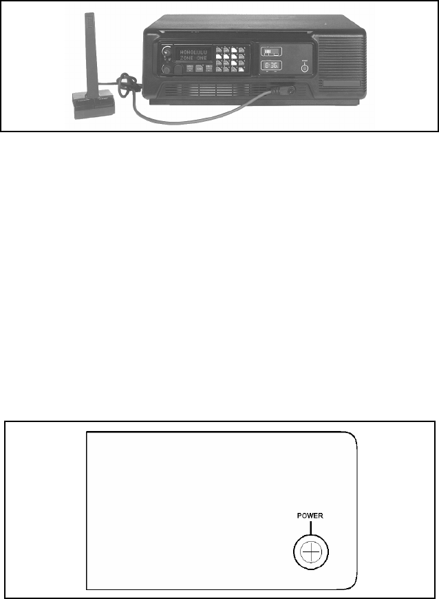
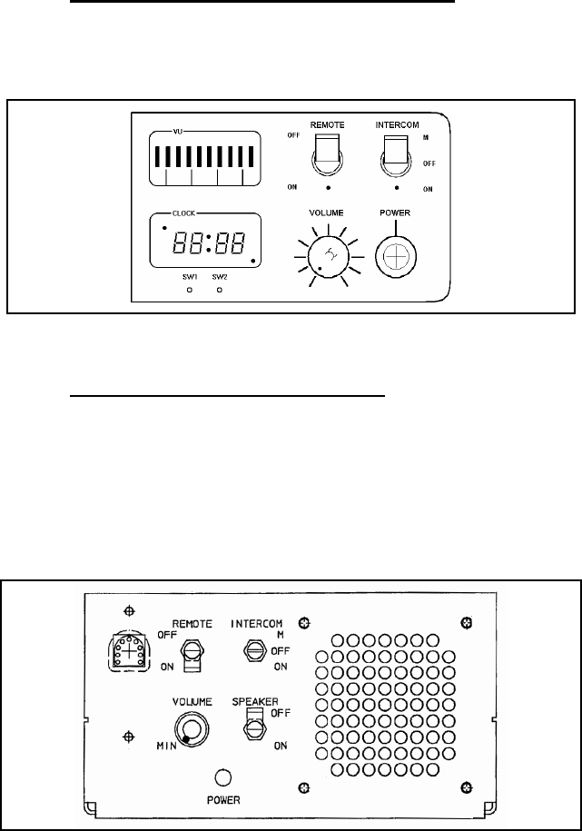
Figure 2-1: Desktop Station Front Panel with VU Meter/Clock
The M/A-COM® M7100IP Desktop Station is shown in Figure 2-1 This
Station combines the flexibility of a Local Control Station with a Remote
Control Station in one desktop package.
The M7100IP Wall Mount Station is designed specifically for Remote Control
applications with no user accessible controls. The Wall Mount Station
housing is equipped with a key lock to prevent unauthorized entry.
2.1 STANDARD FEATURES
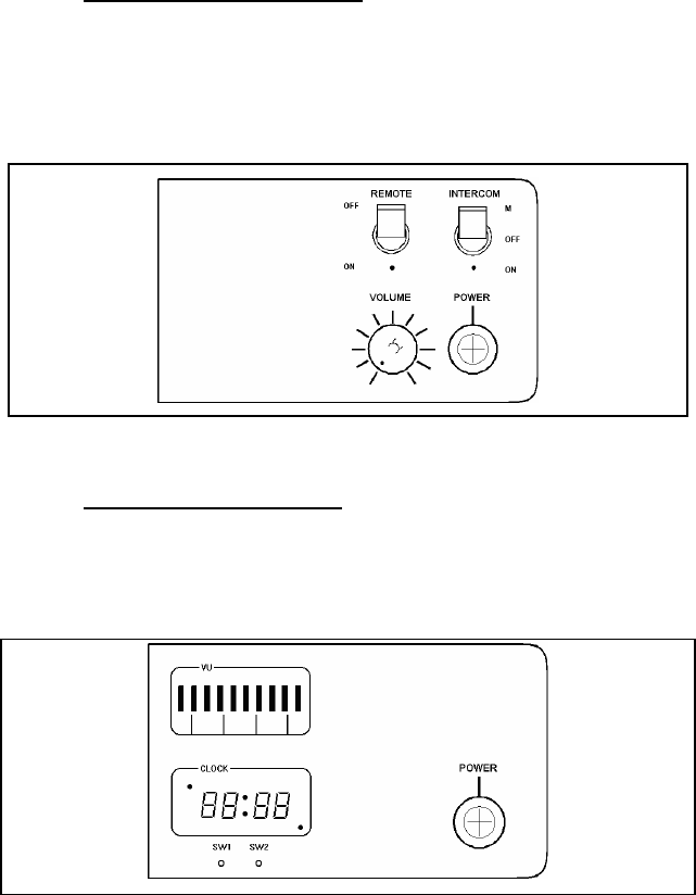
The basic Desktop Station comes equipped with the Standard Control Panel as
shown in Figure 2-2. The Standard Control Panel is equipped with a single
Power LED to indicate the status of the power being supplied to the station.
This indicator is present on all configurations.
Figure 2-2: Standard Control Panel
5
2.2 OPTIONS
The standard Desktop Station can be configured in several different ways
including Remote/Intercom controls, and/or VU (Volume Unit) Meter/Clock
display.
2.2.1 Remote/Intercom Option
Desktop Stations equipped with the Remote/Intercom option (see Figure 2-3)
permits the use of Remote Controllers. Local and Remote Station control is
provided for station functions such as Transmit, Receive and Intercom Audio,
PTT (Press-To-Talk) Control, and Channel Guard Monitor.
Figure 2-3: Remote/Intercom Option Control Panel
2.2.2 VU Meter/Clock Option
The VU Meter/Clock option provides transmit and receive audio level
display, together with a twelve/twenty-four hour digital clock display (see
Figure 2-4).
Figure 2-4: VU/Clock Option Control Panel
6
2.2.3 Remote/Intercom/VU Meter/Clock Option
Desktop Stations with the Remote/Intercom/VU Meter/Clock option have the
full compliment of controls described in sections 2.2.1 and 2.2.2 (see Figure
2-5).
Figure 2-5: Remote/Intercom/VU Meter/Clock Option Control Panel
2.2.4 Wall Mount Station Control Panel
Wall Mount Stations include a basic control panel located inside the housing
(see Figure 2-6). The Wall Mount control panel includes a volume control,
remote ON/OFF switch, intercom ON/OFF switch, microphone jack, power
indicator lamp, and speaker ON/OFF switch. The speaker is unique only to
the Wall Mount Station and is typically turned ON only during servicing. All
other features operate in the same manner as the Desktop Station.
Figure 2-6: Wall Mount Station Control Panel
7

3 CONTROLS AND INDICATORS
3.1 VOLUME CONTROL
The radio volume control is used for Desktop Stations with the Standard
Control Panel (Non-Remote Control Stations). The volume control on the
radio must be variable only for the Local Control Stations.
Desktop Stations equipped with the optional Remote Control Panel are
equipped with a separate volume control located on the Station Control Panel.
This knob controls the level of audio fed to the Station speaker as determined
by the Intercom and Remote Switch positions.
3.2 REMOTE/INTERCOM SWITCHES
These switches control the audio paths for stations equipped with one of
several Remote Control options. Audio control is accomplished between
remote and local microphones, the radio, and remote and local speakers. The
Remote switch allows for remote control of the radio. The Intercom switch
allows communication between the Desktop Station and a Remote Controller.
3.3 VU METER AND CLOCK
The VU Meter displays, in bar graph format, transmit/receive audio levels.
The time is displayed in an “Hours: Minutes” format.
NOT
E
An illuminated indicator in the lower right corner of the
clock display indicates that the internal battery of the VU
Meter/Clock is defective or the VU Meter calibration data
has been lost. Contact a service technician to correct the
problem.
3.4 DESK MICROPHONE
The desk microphone is equipped with the traditional PTT (Push-to-Talk)
Transmit button, and a Monitor button. In configurations using Channel
Guard, the Microphone Monitor button provides the operator the ability to
listen for other users on the selected channel before transmitting. This helps
to prevent unnecessary interference to other users. On stations equipped with
the Local/Remote option, the functionality of the microphone PTT button is
determined by the Local/Remote switch settings (see Section 4.2).
8

4 STATION OPERATION
4.1 BASIC STATION
Turn on the main ON/OFF power switch located on the rear of the Station
housing. The front panel LED illuminates, indicating that the power supply to
the cooling fan is on. Fan operation is temperature controlled.
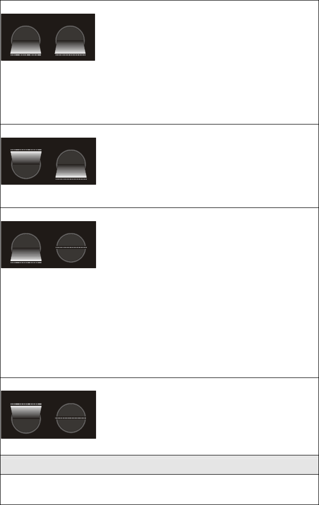
4.2 REMOTE/INTERCOM
These switches control the audio paths between remote and local
microphones, the radio, and remote and local speakers. There are four
possible switch configurations.
REMOTE INTERCOM
OFF
ON
M
OFF
ON
1
With this switch configuration,
intercom communication is possible
b
etween the Desktop Station and the
Remote Controller. The Remote
Controller can also key the radio
transmitter and hear the receiver's
audio output.
When the Desktop Mic is keyed, there is no connection to the radio
transmitter. If the radio receiver is squelched, the Remote hears the audio as
an intercom conversation. Should the radio receiver be unsquelched, receiver
audio is heard on both the Desktop speaker and the Remote speaker, with
priority over the intercom message from the Desktop Mic to the Remote
speaker.
The audio from the Remote Mic is heard on the Desktop speaker. The
Remote’s Intercom switch must be OFF to key the Station's radio transmitter.
The audio from the unsquelched radio receiver is heard on both the Station
speaker and the Remote speaker.
Intercom messages from the Remote are muted when radio messages are
being received or when the Desktop Station operator is using the Desktop
Mic.
9

REMOTE INTERCOM
2
This configuration offers interco
m
service only. Neither the Desktop no
r
the Remote Mics can key the radio
transmitter. The radio receiver's audio
can be heard on the Station speaker, bu
t
not on the Remote speaker.
A message from the Desktop Mic is heard on the Remote speaker.
An intercom message from the Remote Mic can be heard on the Desktop
speaker, but only if the Desktop Mic is not active. The Desktop Mic has
priority over the Remote Mic in the intercom connection.
REMOTE INTERCOM
3
This configuration is for remote control
of the radio, without an interco
m
connection. When the Desktop Mic is
keyed, the radio transmitter is keyed
and the Remote Controller is able to
monitor the transmission.
If only the Remote Mic is keyed, and not the Desktop Mic, then the Remote
Mic is connected to the radio transmitter. In addition, the Remote Mic is
connected to the Desktop speaker if the radio receiver is squelched and the
Desktop Mic is not keyed (so that the "Desktop Mic Audio to Line Path" is
inactive).
The radio receiver audio is connected to the Remote speaker if the receiver is
unsquelched. The PA output from the receiver is unconditionally connected
to the Desktop speaker, but is subject to the radio's internal squelch.
REMOTE INTERCOM
OFF
ON
M
OFF
ON
4
This configuration is used when
operating the Desktop Station as a
radio. If the Desktop Mic is keyed, it is
connected to the radio transmitter only.
The radio receiver's PA audio output is
connected to the Desktop speaker only.
A summary of these four combinations of Intercom and Remote switches is
given in Section 5: LOCAL/REMOTE CONTROLS SUMMARY.
10

4.3 CLOCK
NOT
E
The VU Meter bar graphic display is inactive during time
setting mode.
4.3.1 12/24 hour mode
Below the clock display, there are two switches: SW1 and SW2.
1. Press SW1 for approximately 1 second. "12__" or "24__" will appear in
the display.
2. Press SW2 to toggle between two modes.
3. Press SW1 for approximately 1 second to select required mode.
4.3.2 Setting the Time
Having selected the hour mode, the time will display (no flashing colon) with
hours intensified.
Press SW2 to advance the hours. Holding SW2 down will automatically
advance the clock in increments of about three counts per second. Note the
dot in the upper left indicates PM.
1. Press SW1 for approximately 1 second when the correct hour is
displayed. The time will display with minutes intensified.
2. Press SW2 to advance the minutes.
3. Press SW1 for approximately 1 second when the correct minutes are
displayed.
4.3.3 Light Intensity
SW2 controls the VU Meter/Clock display intensity. There are four settings
available. Press SW2 to toggle through the intensities. When the correct
level is reached, and the reference clock advances to the next minute, press
SW1 for approximately 1 second.
11

12
4.4 TONE REMOTE CONTROLLER
Tone Remote Controllers are used to control Remote Control base stations
from locations not near the base station. Remote operation is accomplished
over telephone lines or a continuously keyed radio frequency link.
Typical Tone Remote Controllers are capable of selecting up to four
predefined radio channels, systems, groups, or special call combinations. The
presets are programmed into the radio using PC Programmer.
The Controller and Desktop Station can operate as an intercom by setting the
Intercom switch to ON or M.
Remotes can be disabled by setting the Station Remote switch to OFF.
4.5 5-FUNCTION REMOTE CONTROLLER
The 5-Function Remote Controller is a versatile, full-function controller used
for operating and controlling a remotely located EDACS® base station.
Remote operation is accomplished over telephone lines or a continuously
keyed radio frequency link. The Controller is capable of selecting up to five
software defined radio systems, group, or special call combinations. The
presets are programmed into the radio using M/A-COM ProGrammer™
software.
The Controller and Desktop Station can operate as an intercom by setting the
Intercom switch to ON or M. Remotes can be disabled by setting the Station
Remote switch to OFF.
4.5.1 Making a Call from a Remote Controller
1. Select the desired function/frequency switch on the Controller.
2. Use the Monitor function (if equipped) and wait for a clear channel to
proceed.
3. Key the Mic PTT to make a call. For EDACS wait for a short beep
before beginning to speak. Release the PTT when finished.
4. Adjust the Volume as necessary while receiving a call.
5 LOCAL/REMOTE CONTROLS SUMMARY
Remote Mic ⎯⎯> Radio Xmtr
Remote Mic ⎯⎯> Station Spkr
Desktop Mic ⎯/⎯> Radio Xmtr
Desktop Mic ⎯⎯>
Remote Spkr if Rx is
muted; otherwise,
Rx⎯⎯>Remote Spkr
& Station Spkr
REMOTE INTERCOM
OFF
ON
M
OFF
ON
Rx Audio ⎯⎯> Station Spkr & Remote
Spkr.
Remote Mic ⎯/⎯> Radio Xmtr
Remote Mic ⎯⎯> Station Spkr, if Desktop
Mic PTT inactive
Desktop Mic ⎯/⎯> Radio Xmtr
Desktop Mic ⎯⎯> Remote Spkr
Rx Audio ⎯/⎯> Remote Spkr
REMOTE
OFF
ON
M
OFF
ON
INTERCOM
Rx Audio ⎯⎯> Station Spkr
Remote Mic ⎯⎯>
Radio Xmtr, if no
Desktop Mic; otherwise,
with Desktop Mic PTT,
Desktop Mic ⎯⎯> Radio
Xmtr
Remote Mic ⎯⎯>
Desk Spkr, if Desktop
Mic PTT inactive,
otherwise Remote Mic
muted
Desktop Mic ⎯⎯> Radio Xmtr with Desktop
Mic PTT
Desktop Mic ⎯⎯> Remote Spkr
Rx Audio ⎯⎯> Remote Spkr, if Rx
unmuted
REMOTE INTERCOM
OFF
ON
MOFF
ON
TX PA Audio ⎯⎯> Station Spkr
Remote Mic ⎯/⎯> Radio Xmtr
Remote Mic ⎯/⎯> Station Spkr
Desktop Mic ⎯⎯> Radio Xmtr
Desktop Mic ⎯/⎯> Remote Spkr
Rx Audio ⎯/⎯> Remote Spkr
REMOTE INTERCOM
OFF
ON
M
OFF
ON
Rx PA Audio ⎯⎯> Station Spkr
KEY
⎯⎯> = connection
⎯/⎯> = no connection
13
14
6 WARRANTY
A. M/A-COM, Inc. (hereinafter "Seller") warrants to the original purchaser for use
(hereinafter "Buyer") that Equipment manufactured by or for the Seller shall be free from
defects in material and workmanship, and shall conform to its published specifications.
With respect to all non-M/A-COM Equipment, Seller gives no warranty, and only the
warranty, if any, given by the manufacturer shall apply. Rechargeable batteries are
excluded from this warranty but are warranted under a separate Rechargeable Battery
Warranty (ECR-7048).
B. Seller’s obligations set forth in Paragraph C below shall apply only to failures to meet the
above warranties occurring within the following periods of time from date of sale to the
Buyer and are conditioned on Buyer’s giving written notice to Seller within thirty (30) days
of such occurrence:
1. for fuses and non-rechargeable batteries, operable on arrival only.
2. for parts and accessories (except as noted in B.1) sold by Seller’s Service Parts
Operation, ninety (90) days.
3. for PANTHER™ Series handportable and mobile radios, two (2) years.
4. for all other equipment of Seller’s manufacture, one (1) year.
C. If any Equipment fails to meet the foregoing warranties, Seller shall correct the failure at
its option (i) by repairing any defective or damaged part or parts thereof, (ii) by making
available at Seller’s factory any necessary repaired or replacement parts, or (iii) by
replacing the failed Equipment with equivalent new or refurbished Equipment. Any
repaired or replacement part furnished hereunder shall be warranted for the remainder of
the warranty period of the Equipment in which it is installed. Where such failure cannot
be corrected by Seller’s reasonable efforts, the parties will negotiate an equitable
adjustment in price. Labor to perform warranty service will be provided at no charge
during the warranty period only for the Equipment covered under Paragraph B.3 and B.4.
To be eligible for no-charge labor, service must be performed at a M/A-COM factory, by
an Authorized Service Center (ASC) or other Servicer approved for these purposes
either at its place of business during normal business hours, for mobile or personal
equipment, or at the Buyer’s location, for fixed location equipment. Service on fixed
location equipment more than thirty (30) miles from the Service Center or other approved
Servicer’s place of business will include a charge for transportation.
D. Seller’s obligations under Paragraph C shall not apply to any Equipment, or part thereof,
which (i) has been modified or otherwise altered other than pursuant to Seller’s written
instructions or written approval or, (ii) is normally consumed in operation or, (iii) has a
normal life inherently shorter than the warranty periods specified in Paragraph B, or (iv)
is not properly stored, installed, used, maintained or repaired, or, (v) has been subjected
to any other kind of misuse or detrimental exposure, or has been involved in an accident.
E. The preceding paragraphs set forth the exclusive remedies for claims based upon
defects in or nonconformity of the Equipment, whether the claim is in contract, warranty,
tort (including negligence), strict liability or otherwise, and however instituted. Upon the
expiration of the warranty period, all such liability shall terminate. The foregoing
warranties are exclusive and in lieu of all other warranties, whether oral, written,
expressed, implied or statutory. NO IMPLIED OR STATUTORY WARRANTIES OF
MERCHANTABILITY OR FITNESS FOR PARTICULAR PURPOSE SHALL APPLY. IN
NO EVENT SHALL THE SELLER BE LIABLE FOR ANY INCIDENTAL,
CONSEQUENTIAL, SPECIAL, INDIRECT OR EXEMPLARY DAMAGES.
This warranty applies only within the United States.
M/A-COM, Inc. M/A-COM, Inc.
1011 Pawtucket Blvd. 221 Jefferson Ridge Parkway
Lowell, MA 01853 Lynchburg, VA 24501
1-877-OPENSKY 1-800-528-7711
ECR-7047C
15
NOTES

M/A-COM Wireless Systems
221 Jefferson Ridge Parkway
Lynchburg, Virginia 24501
(Outside USA, 434-385-2400) Toll Free 800-528-7711
www.macom-wireless.com Printed in U.S.A.