HARRIS TR-0054-E Dual Band P7300 User Manual Manual
HARRIS CORPORATION Dual Band P7300 Manual
UserManual.wiki
>
HARRIS
>
TR 0054 E User Manual
Manual
Navigation menu
Upload a User Manual
Namespaces
Wiki Guide
HTML
PDF
Info
Views
User Manual
Discussion / Help
Navigation

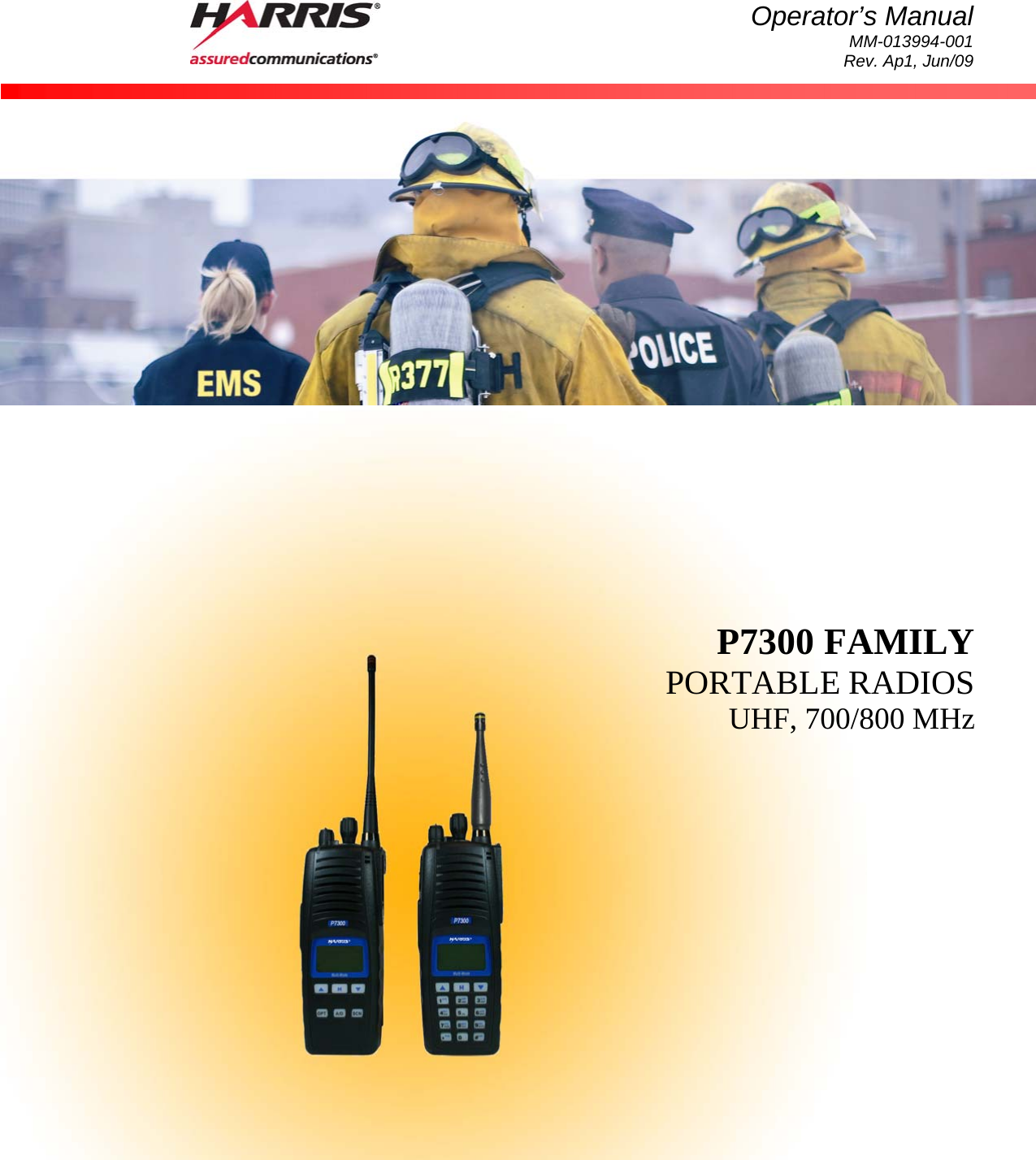
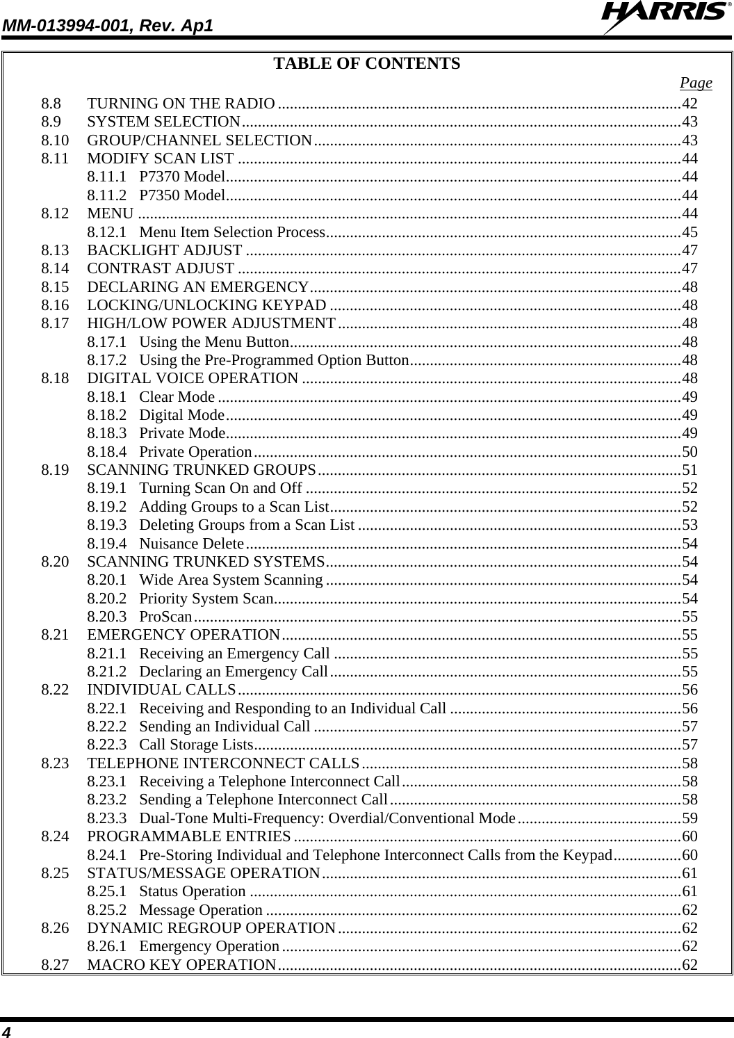
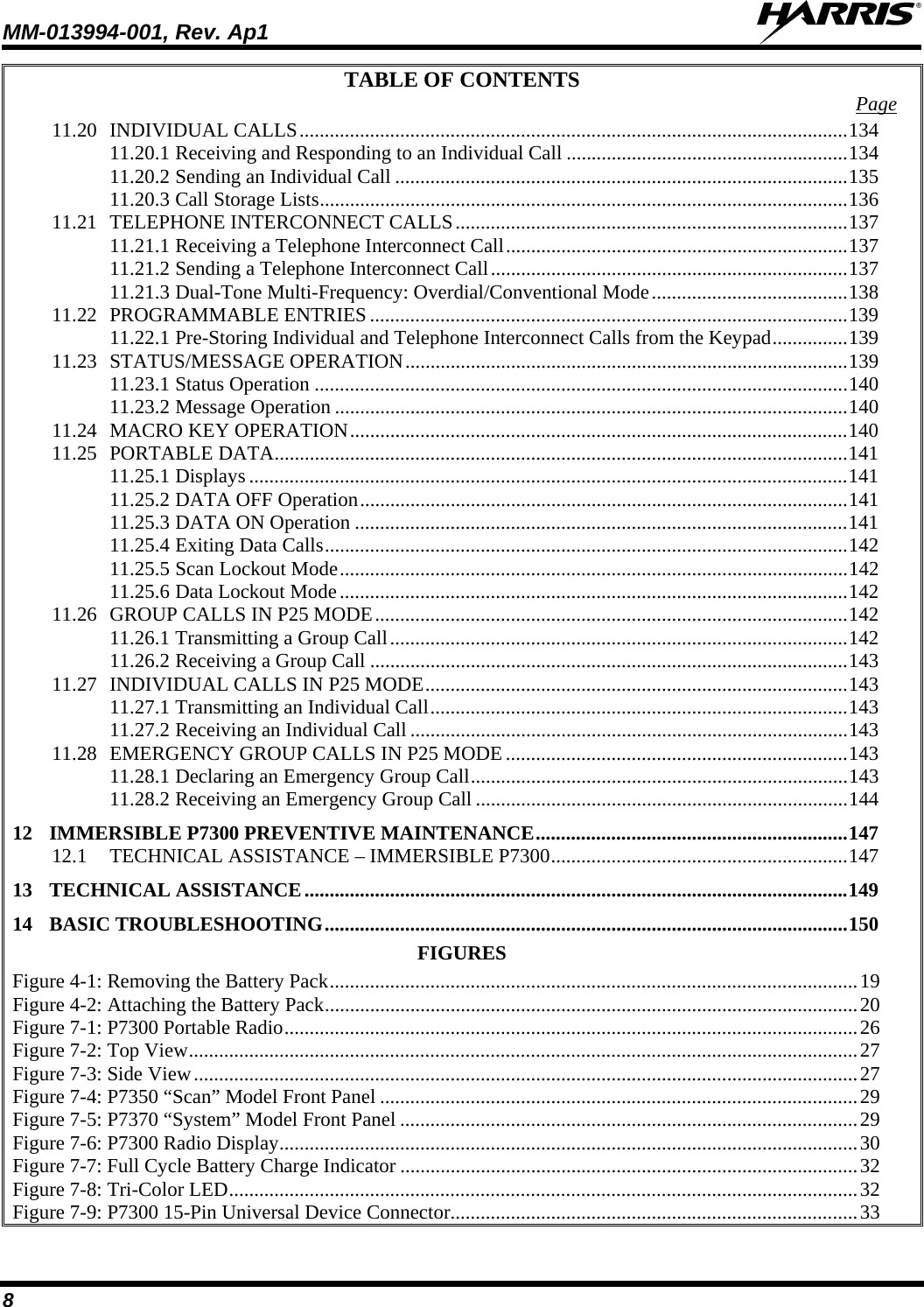


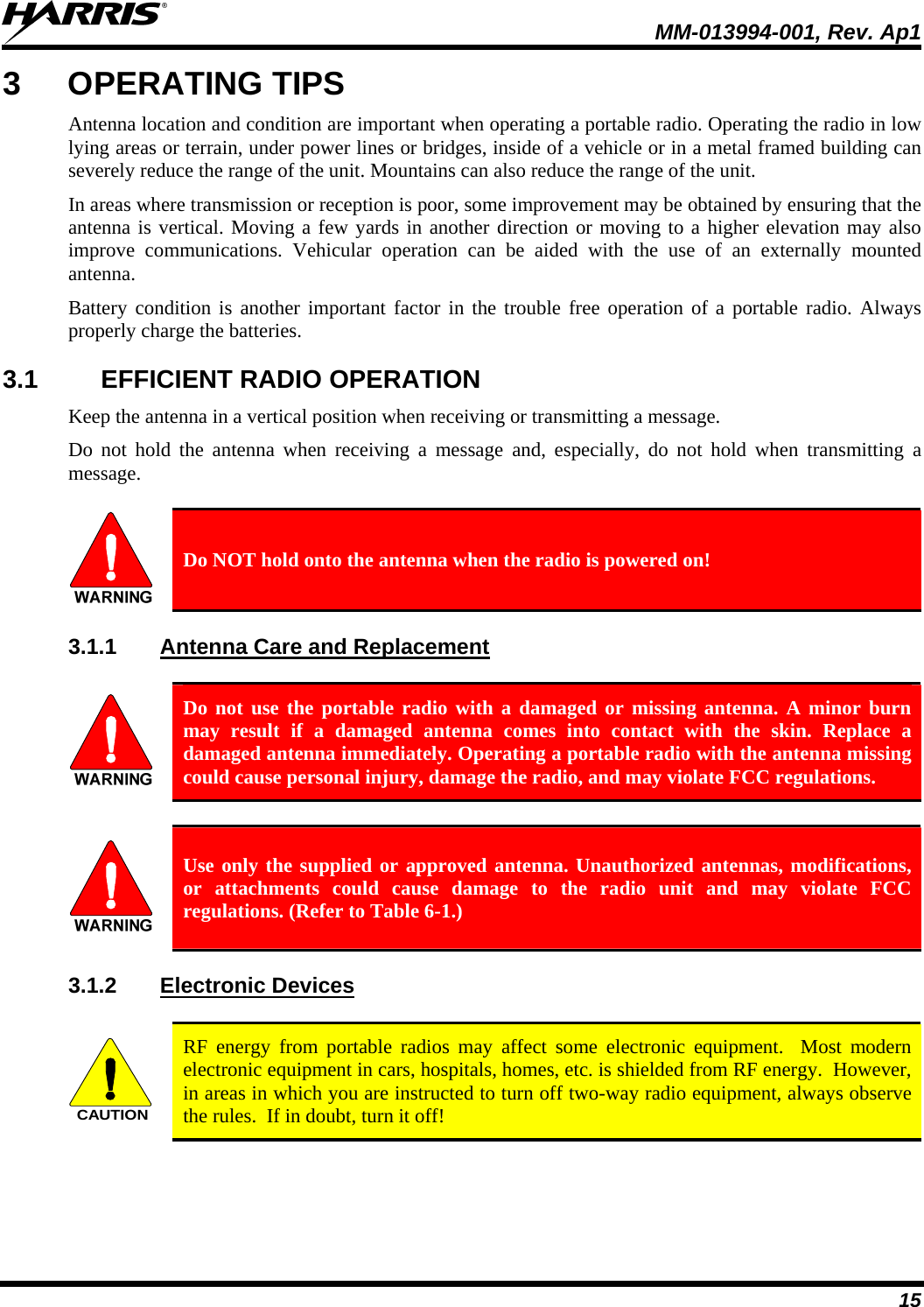
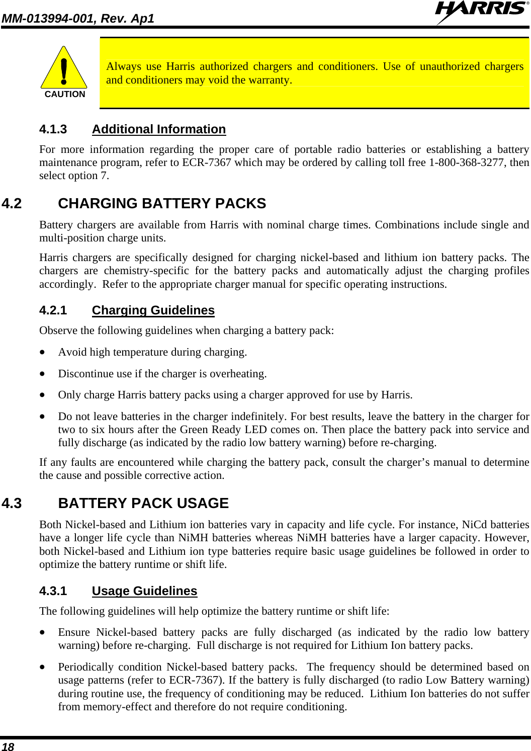


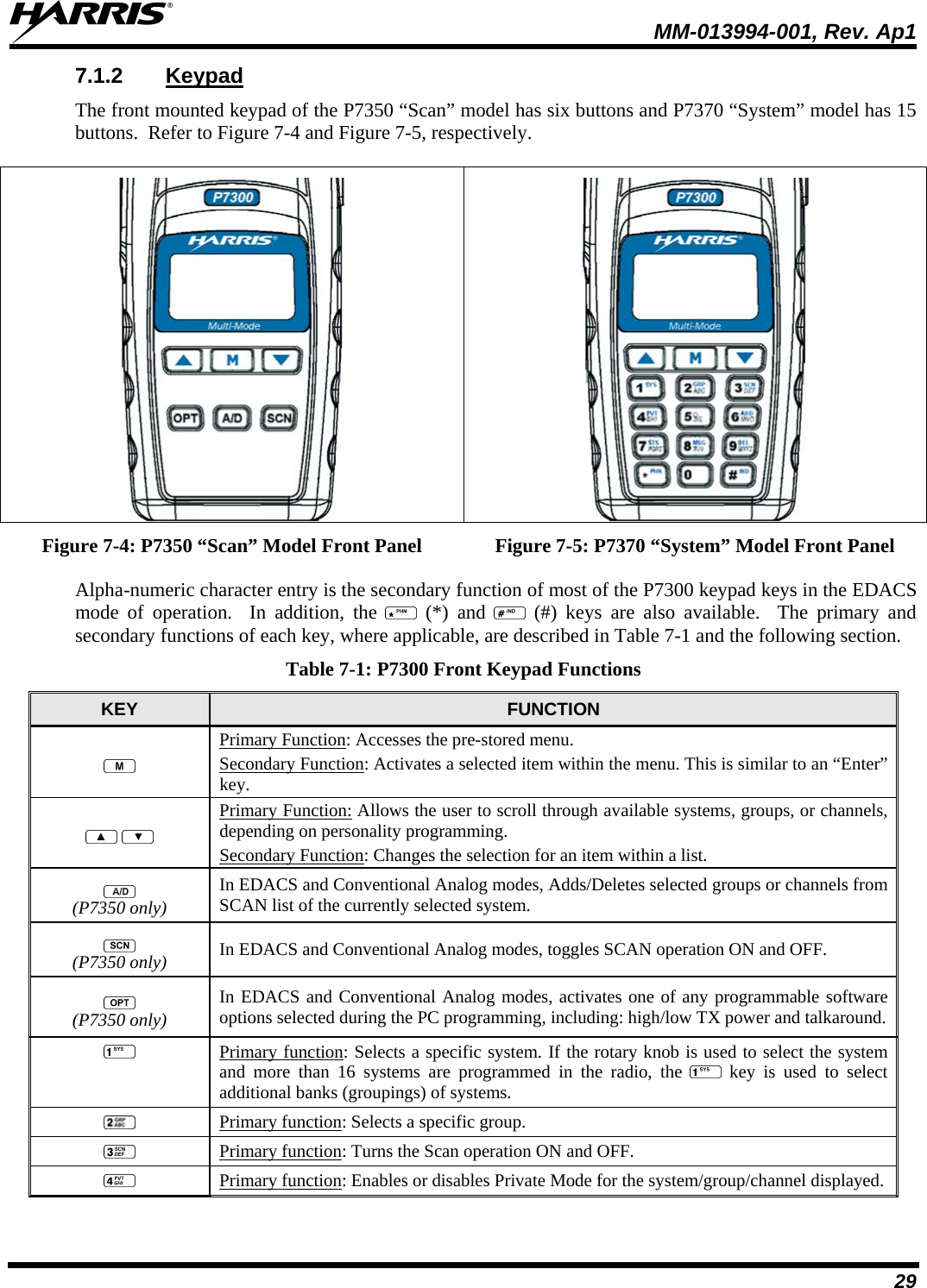

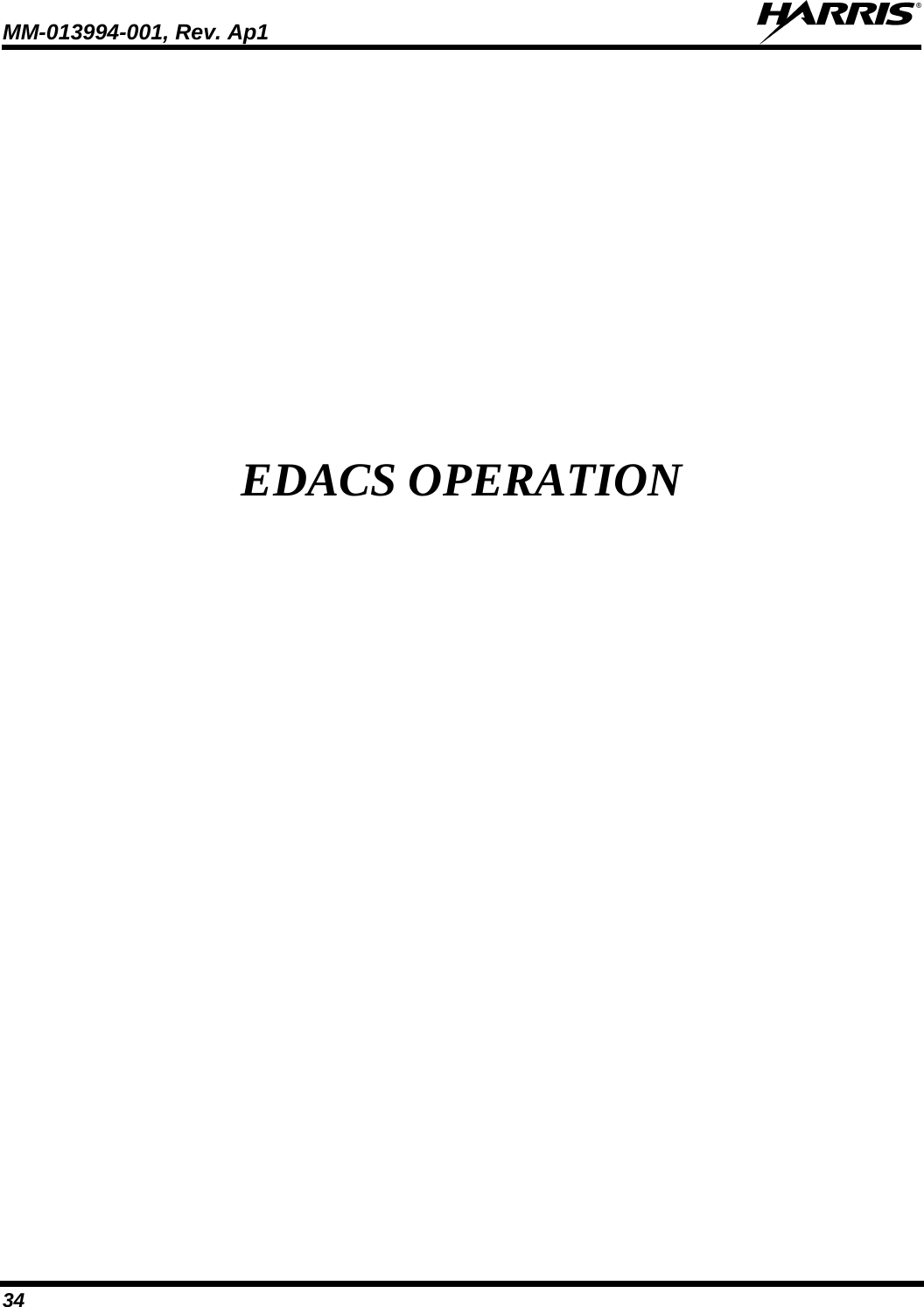
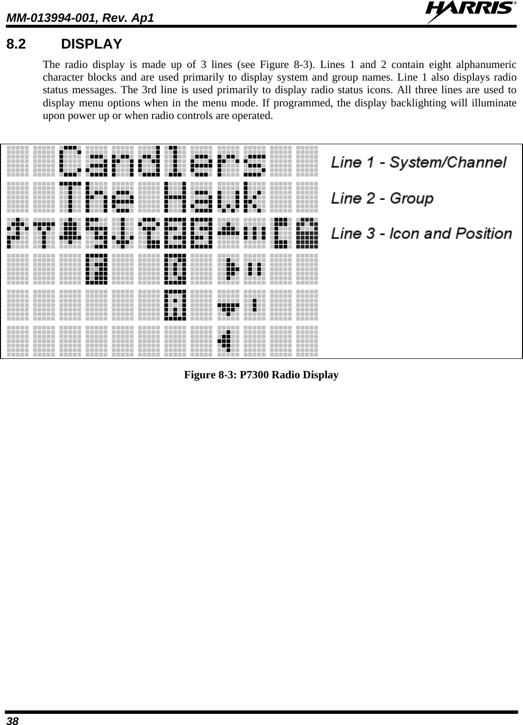
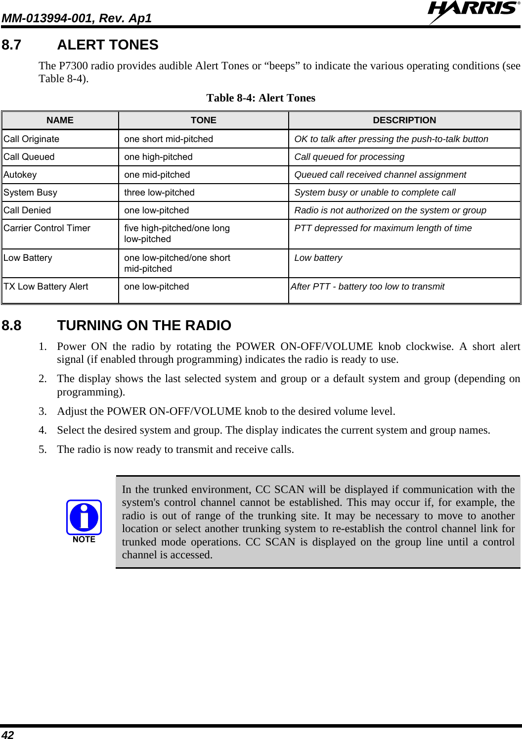
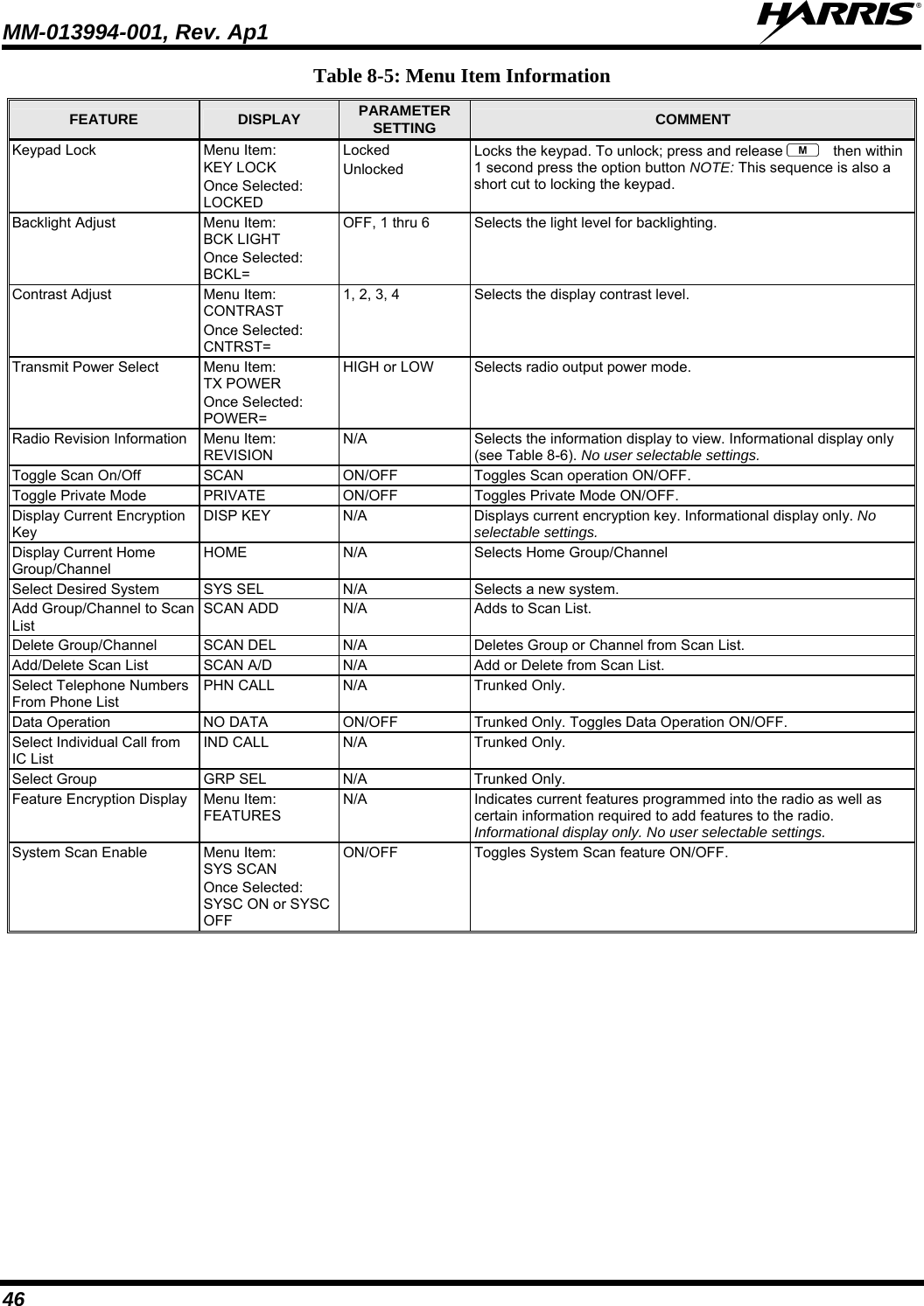
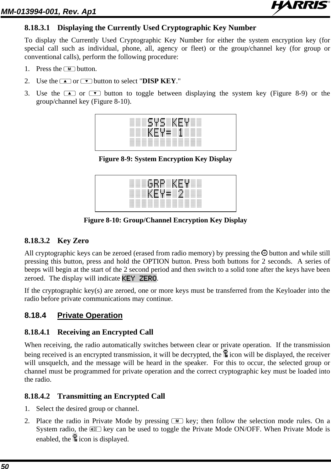
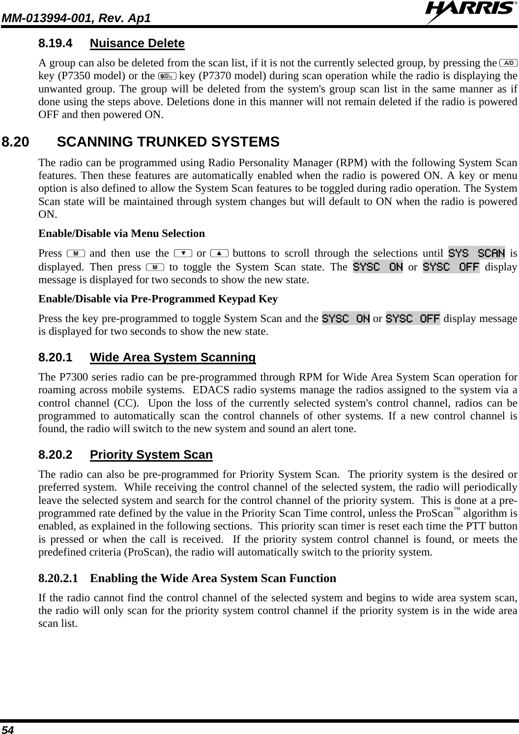
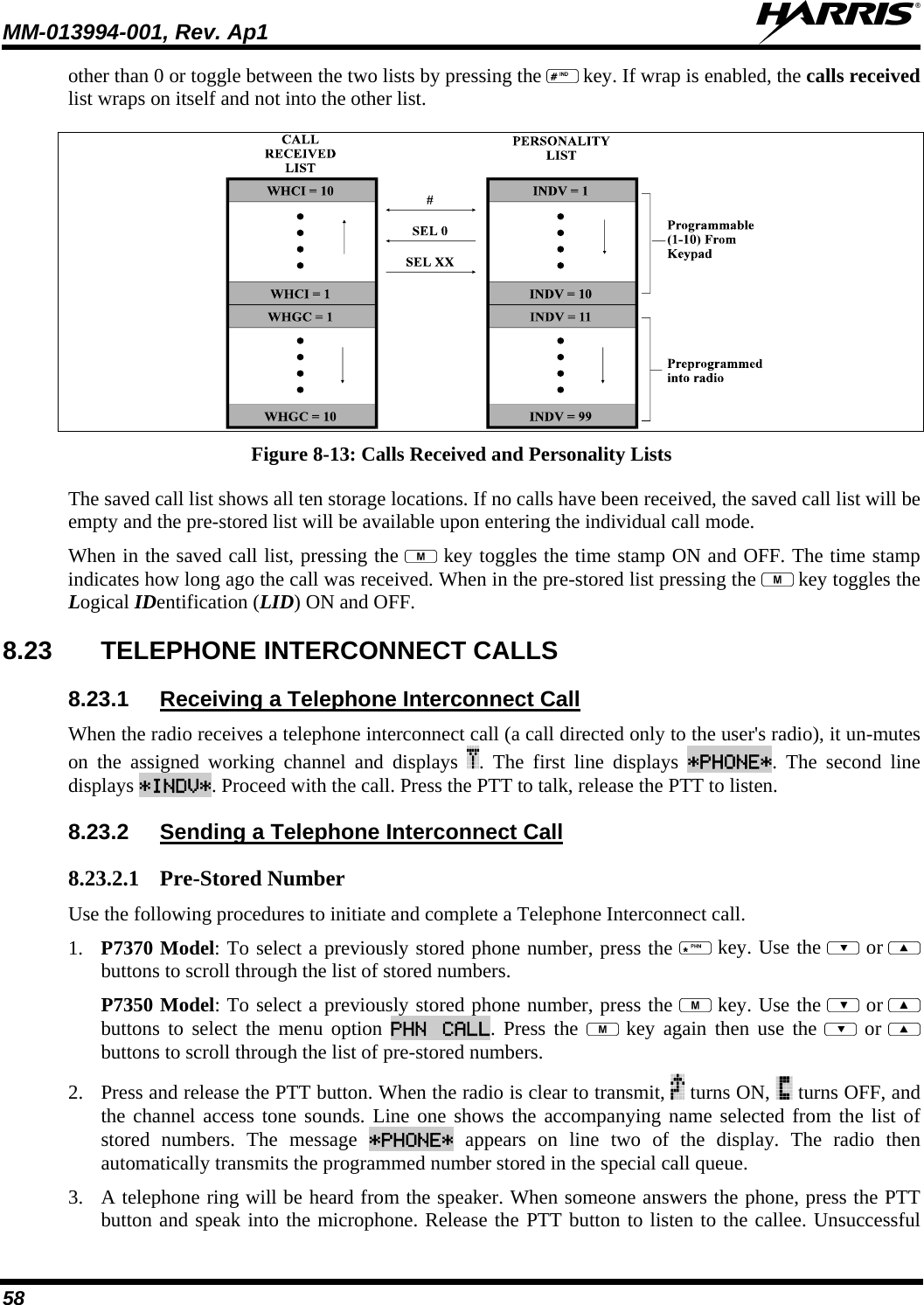
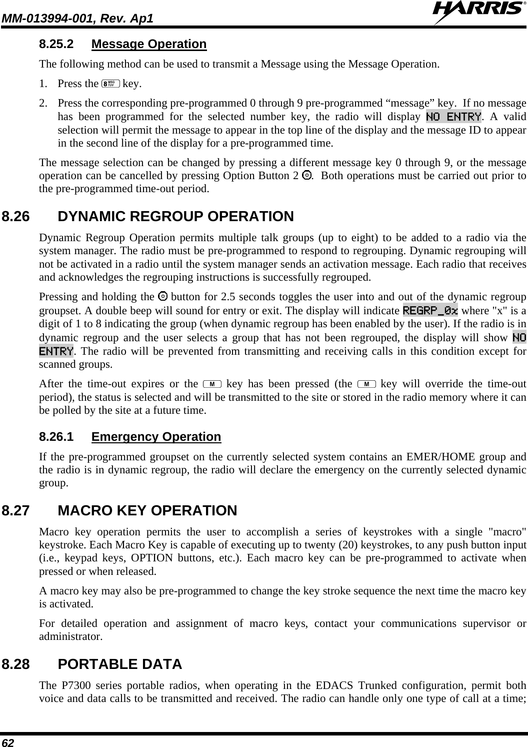


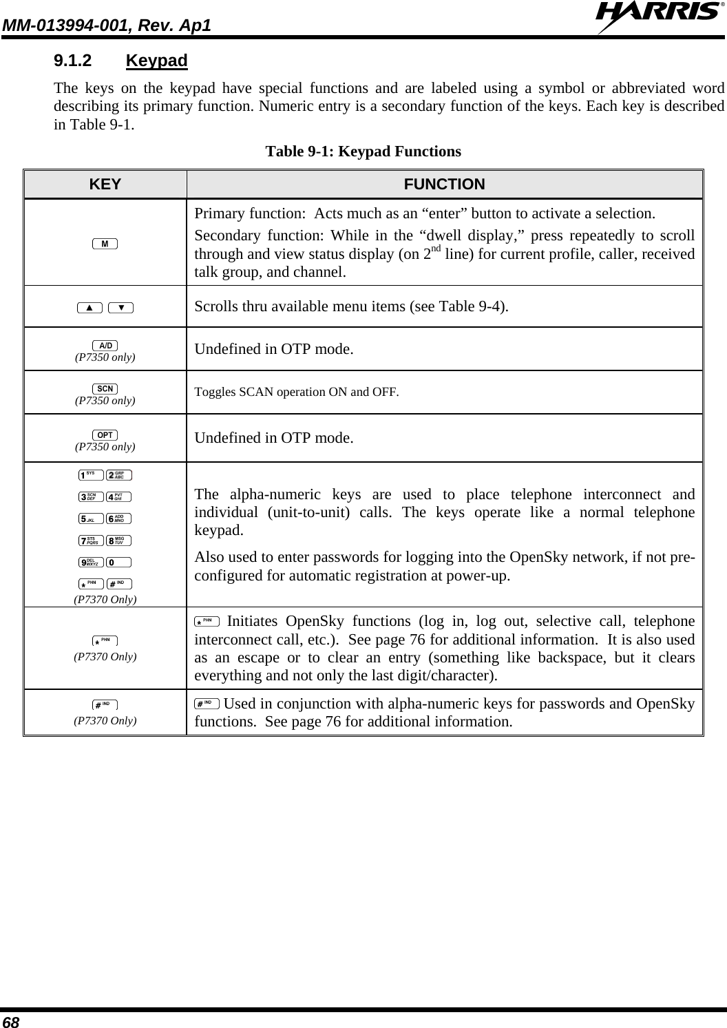
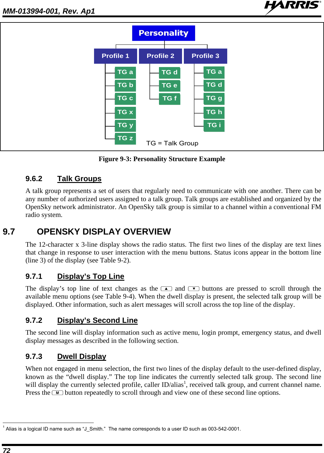
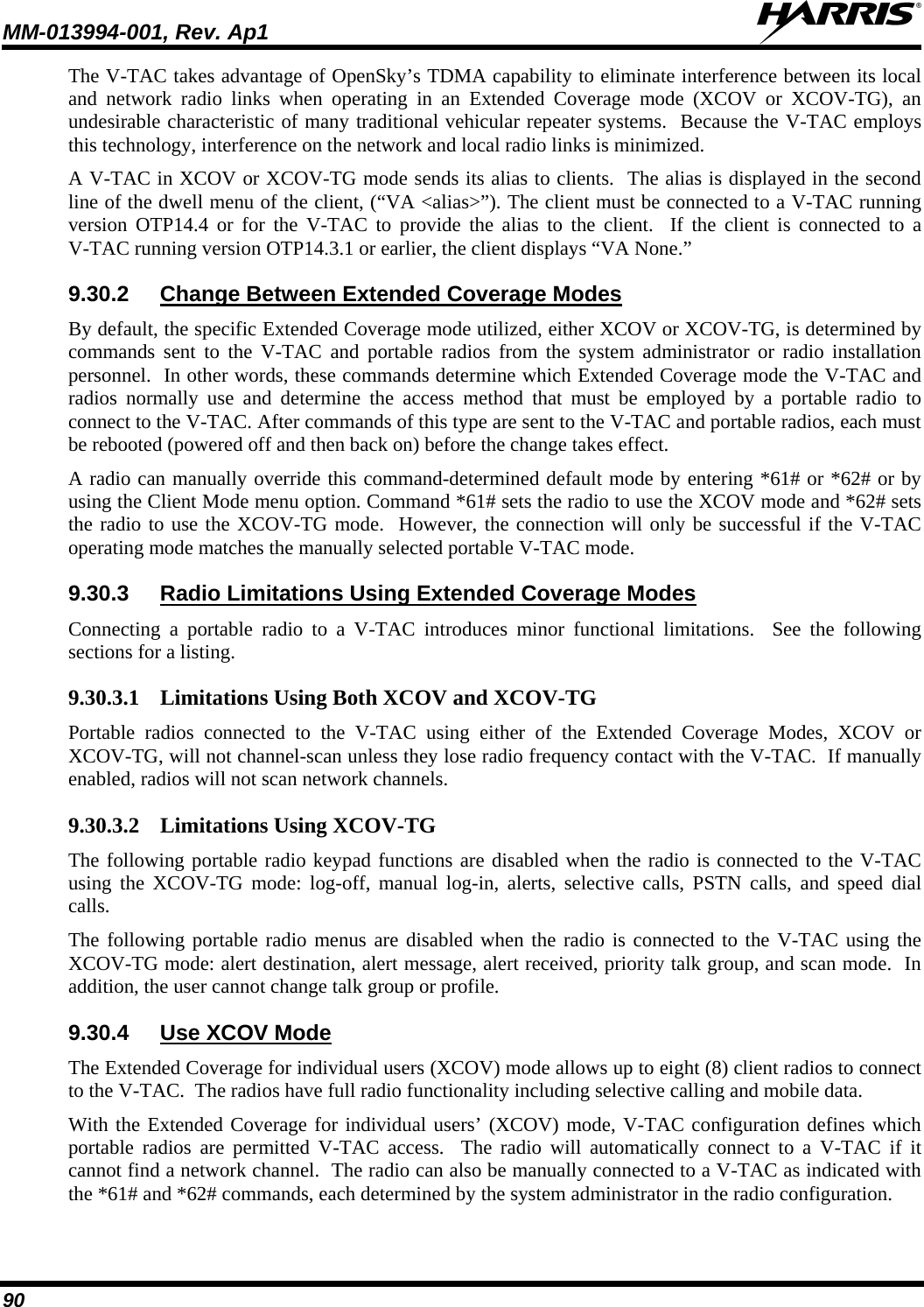
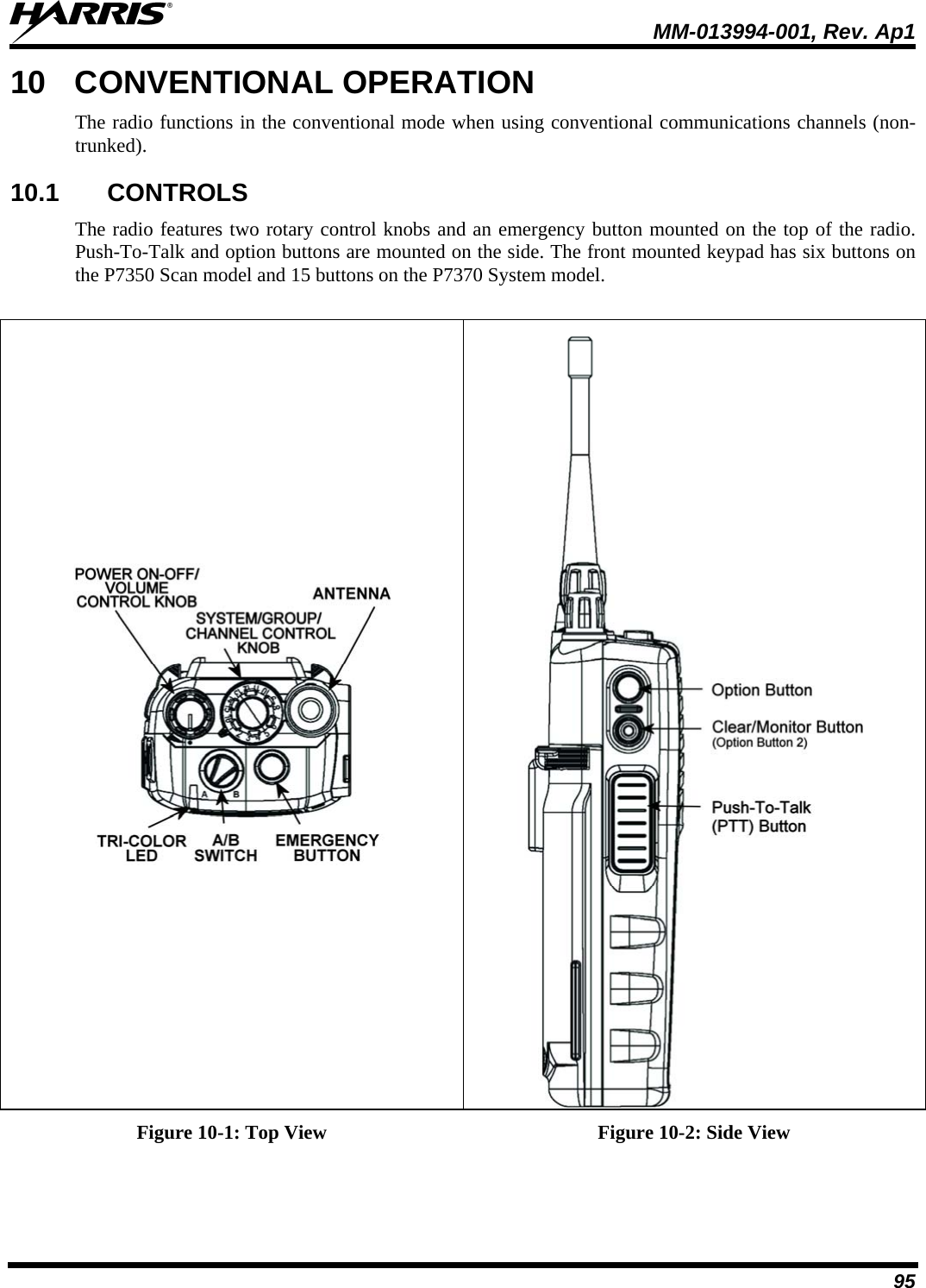
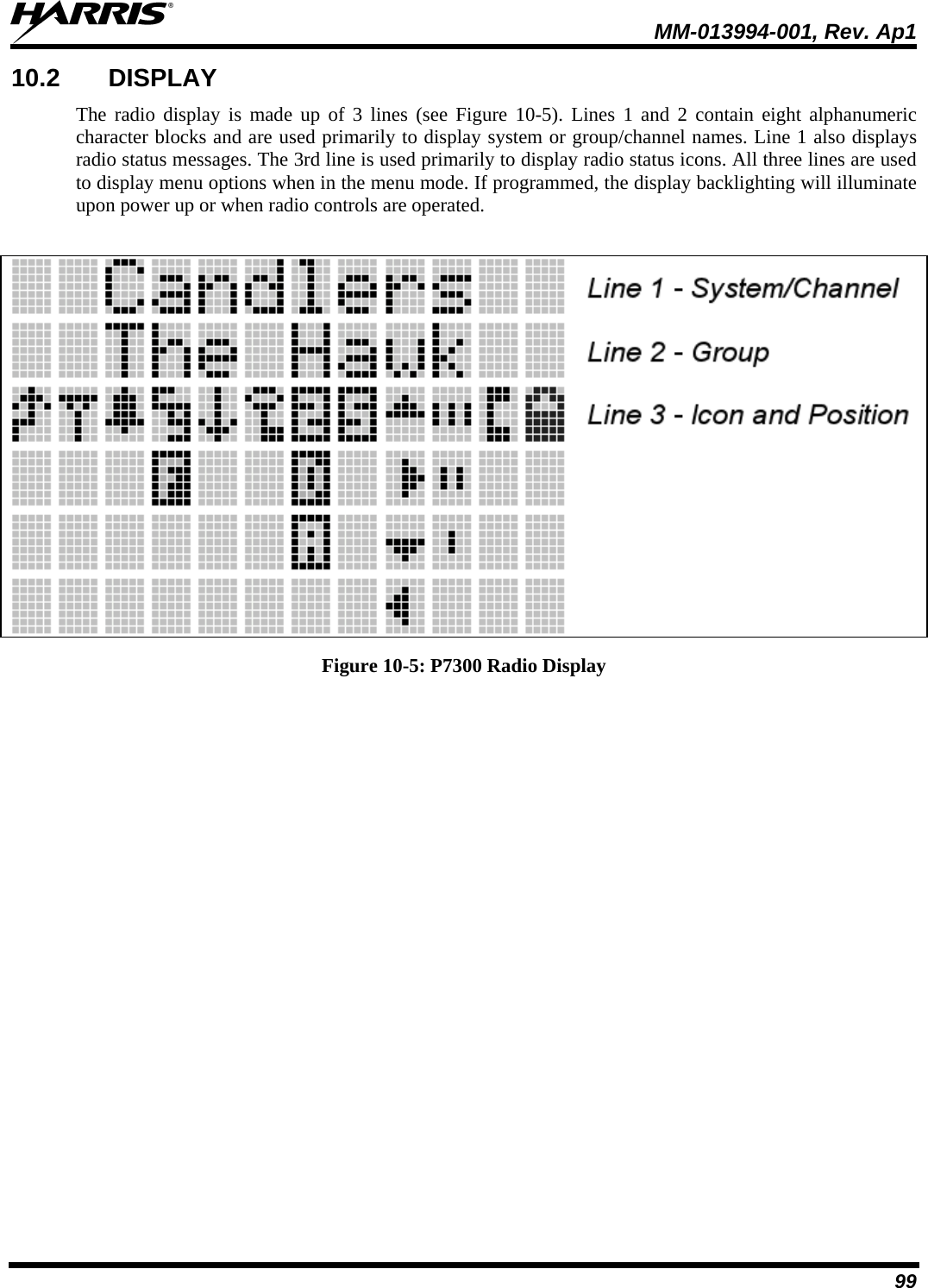
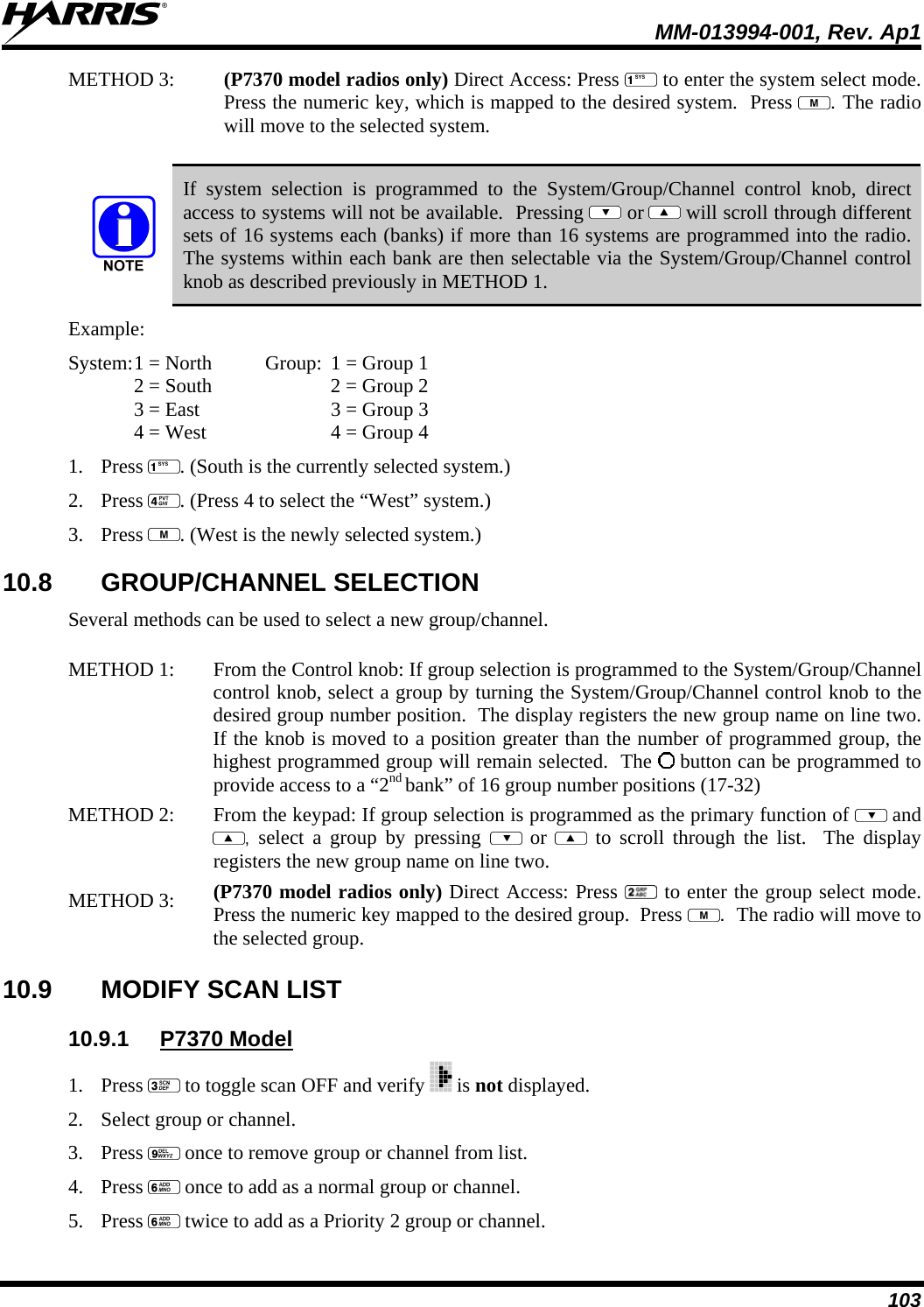
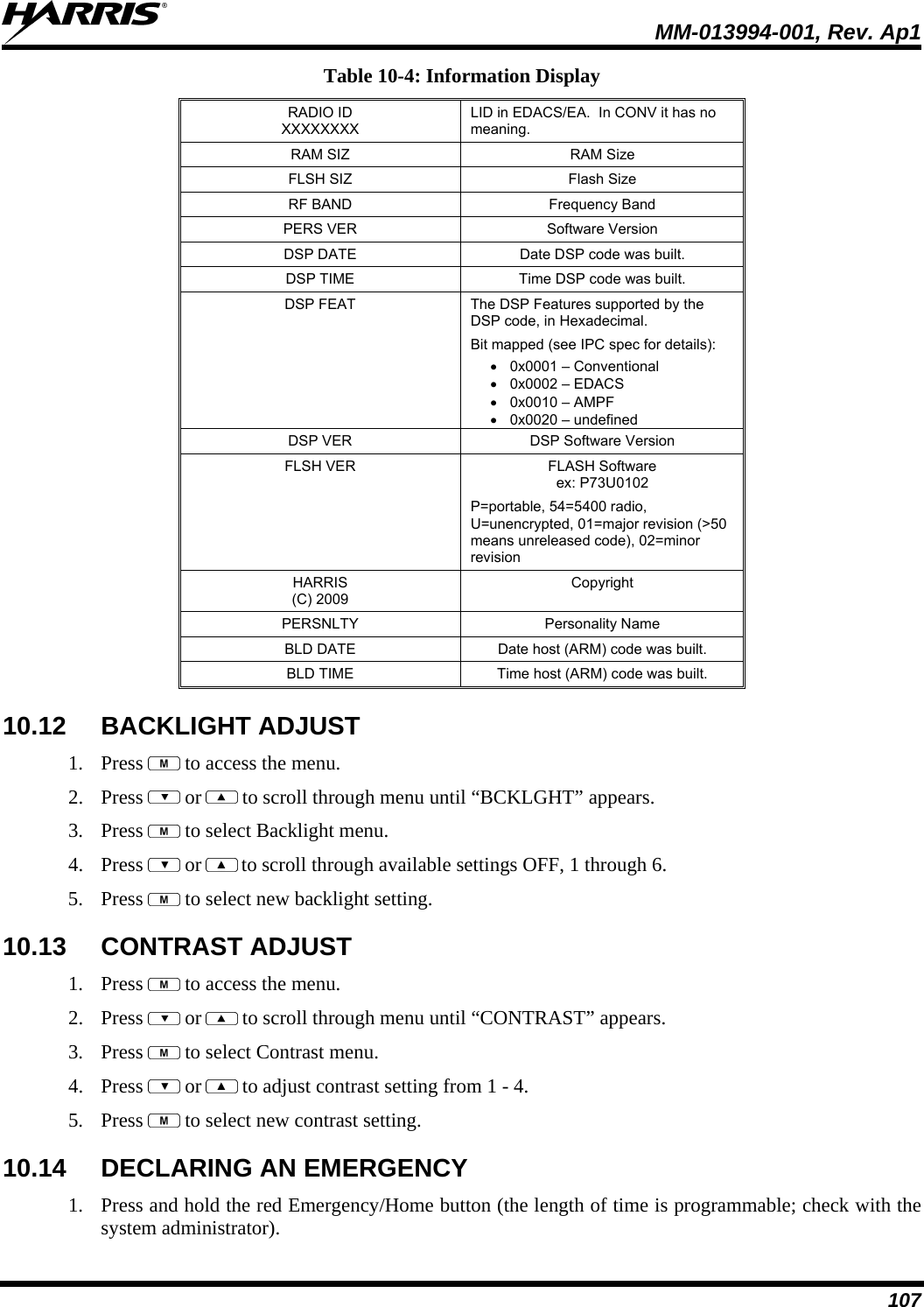
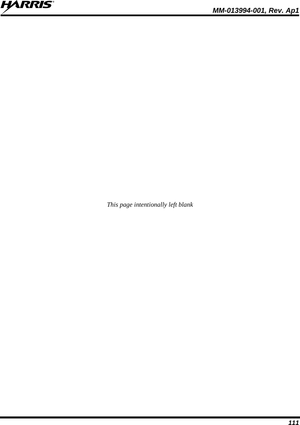
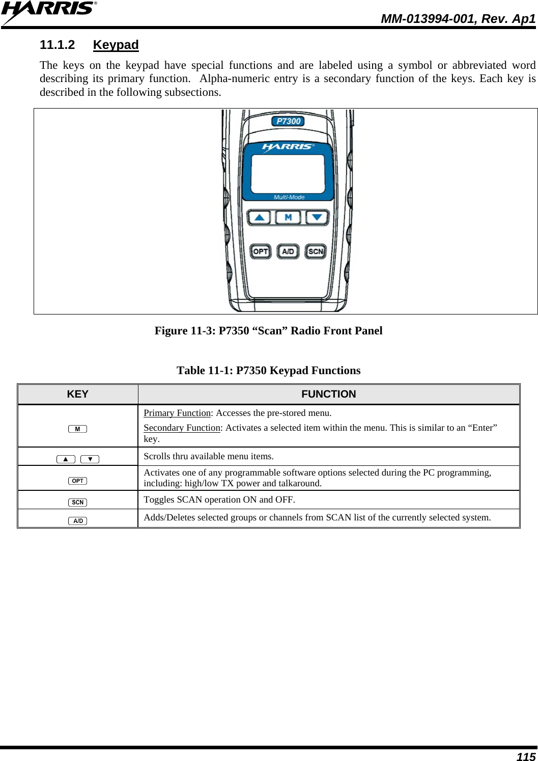
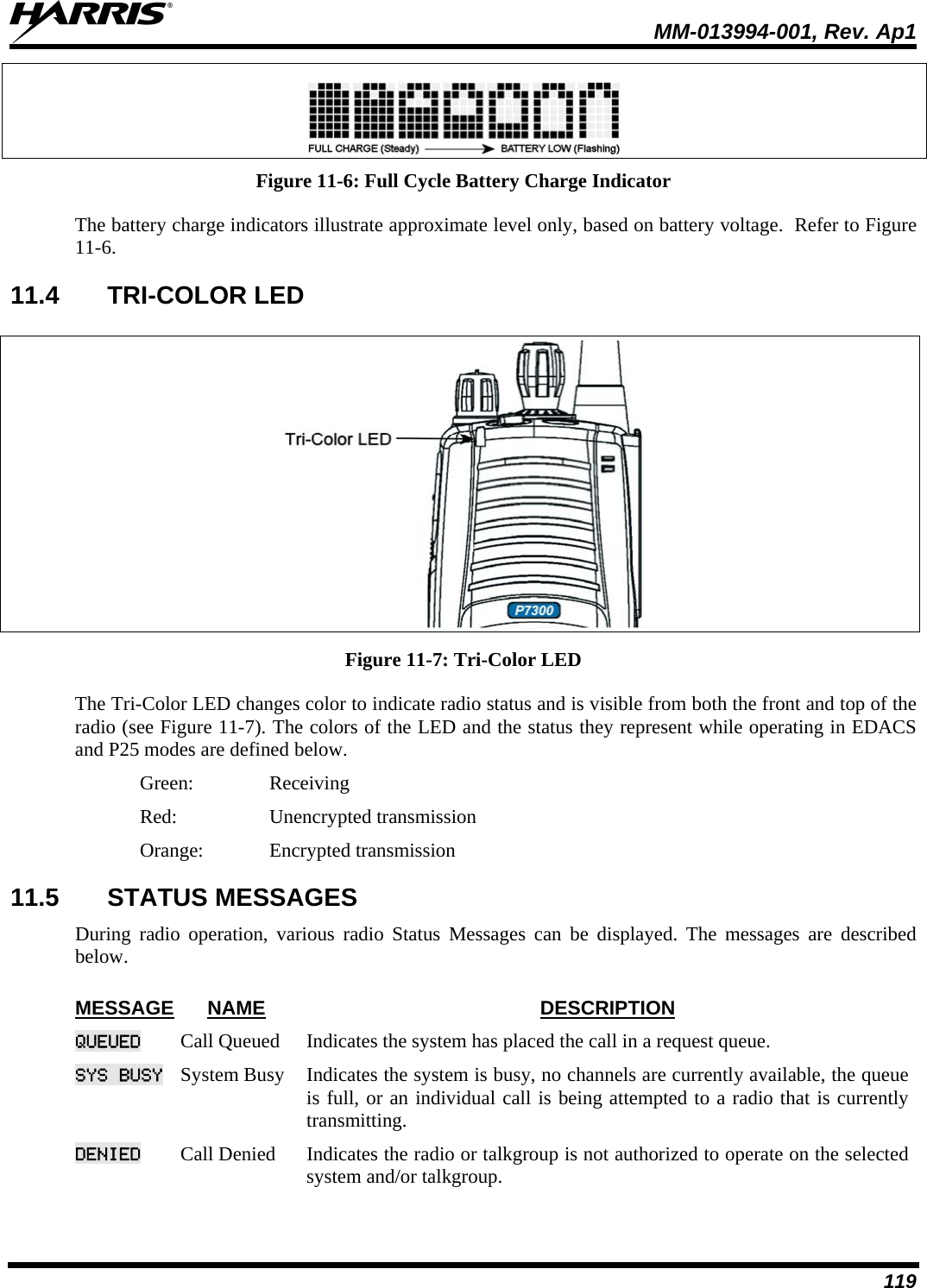
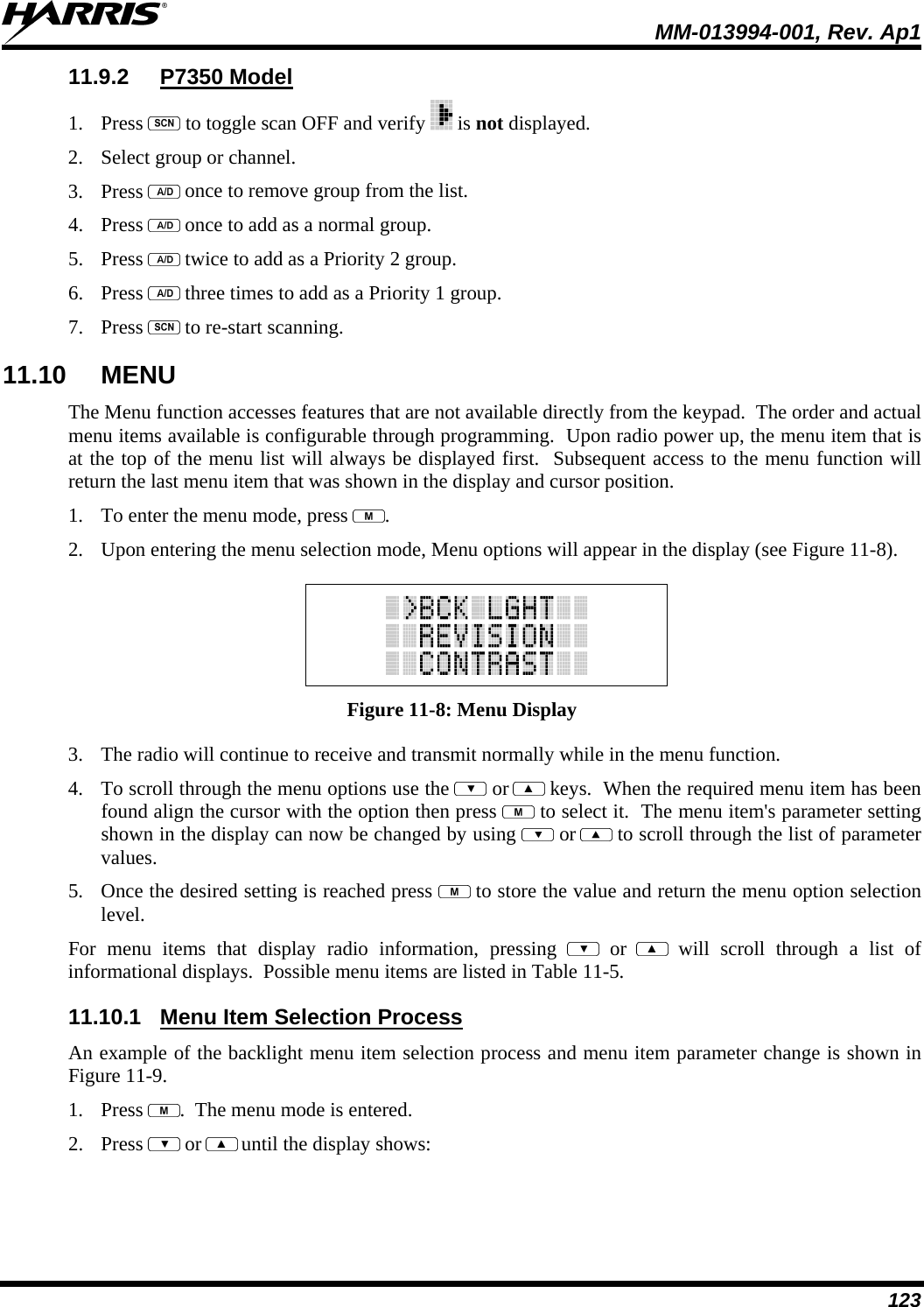
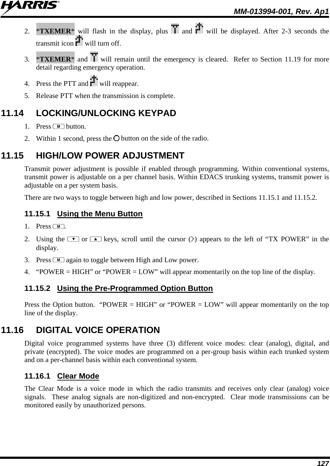
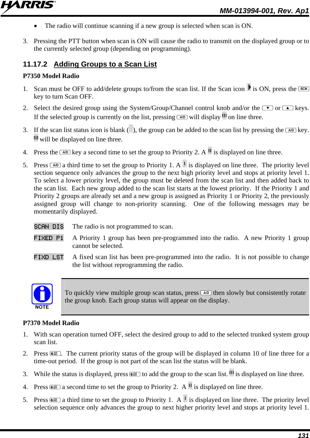
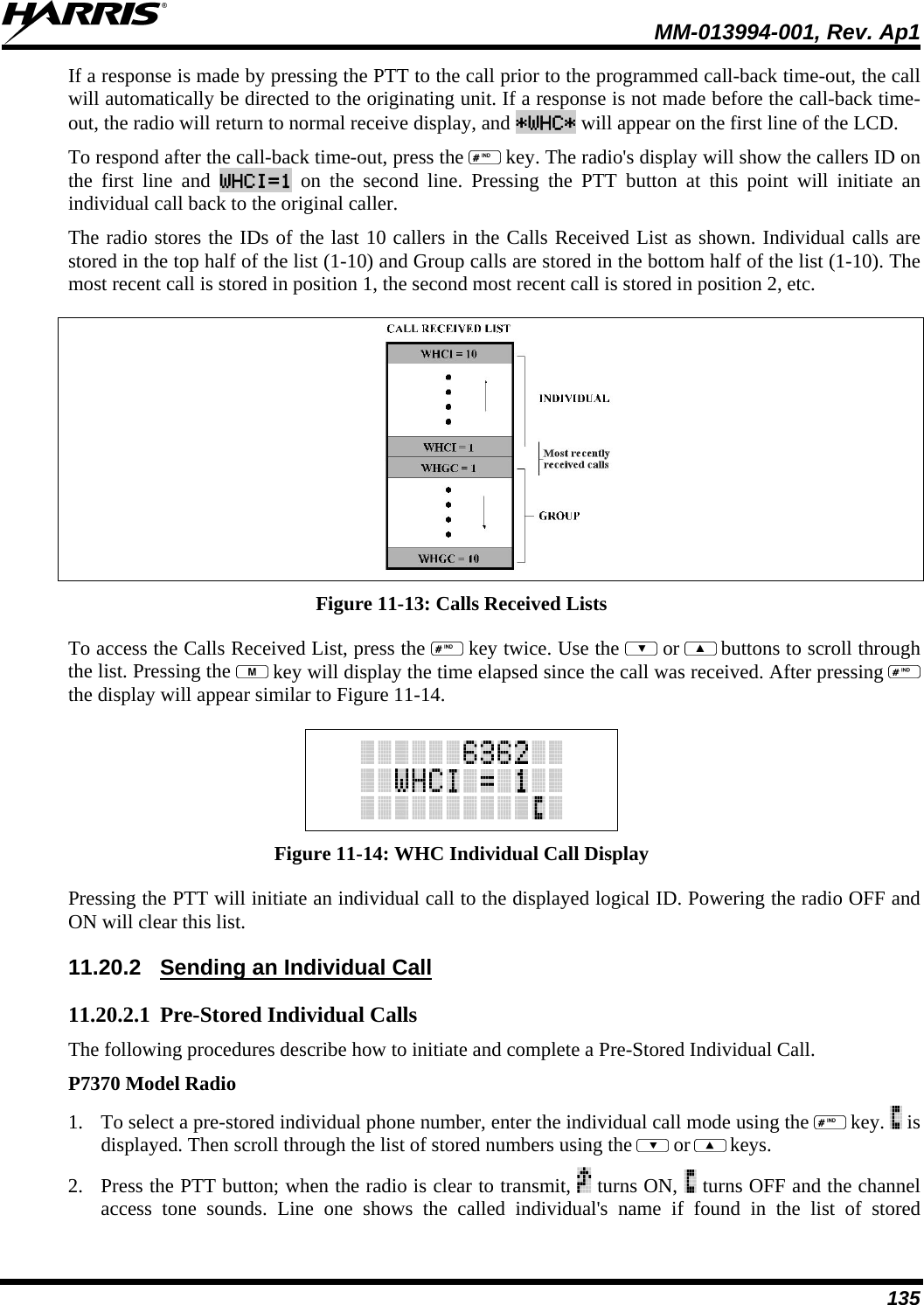
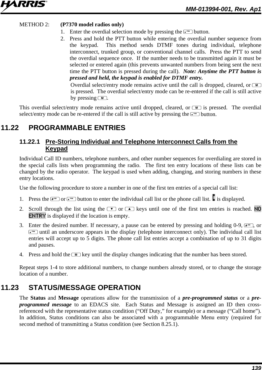
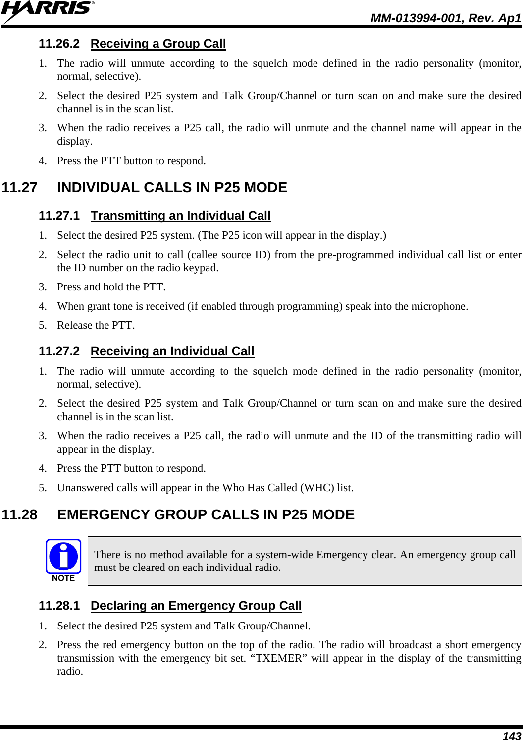
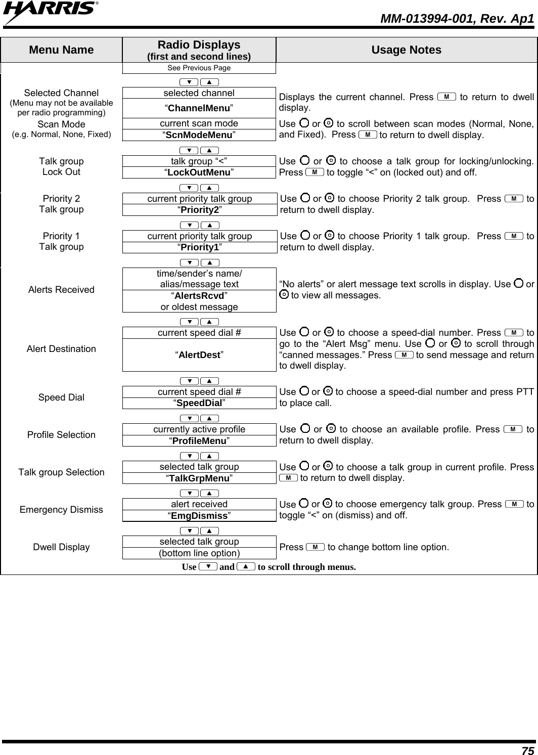
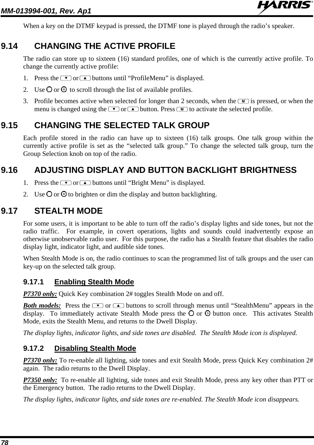
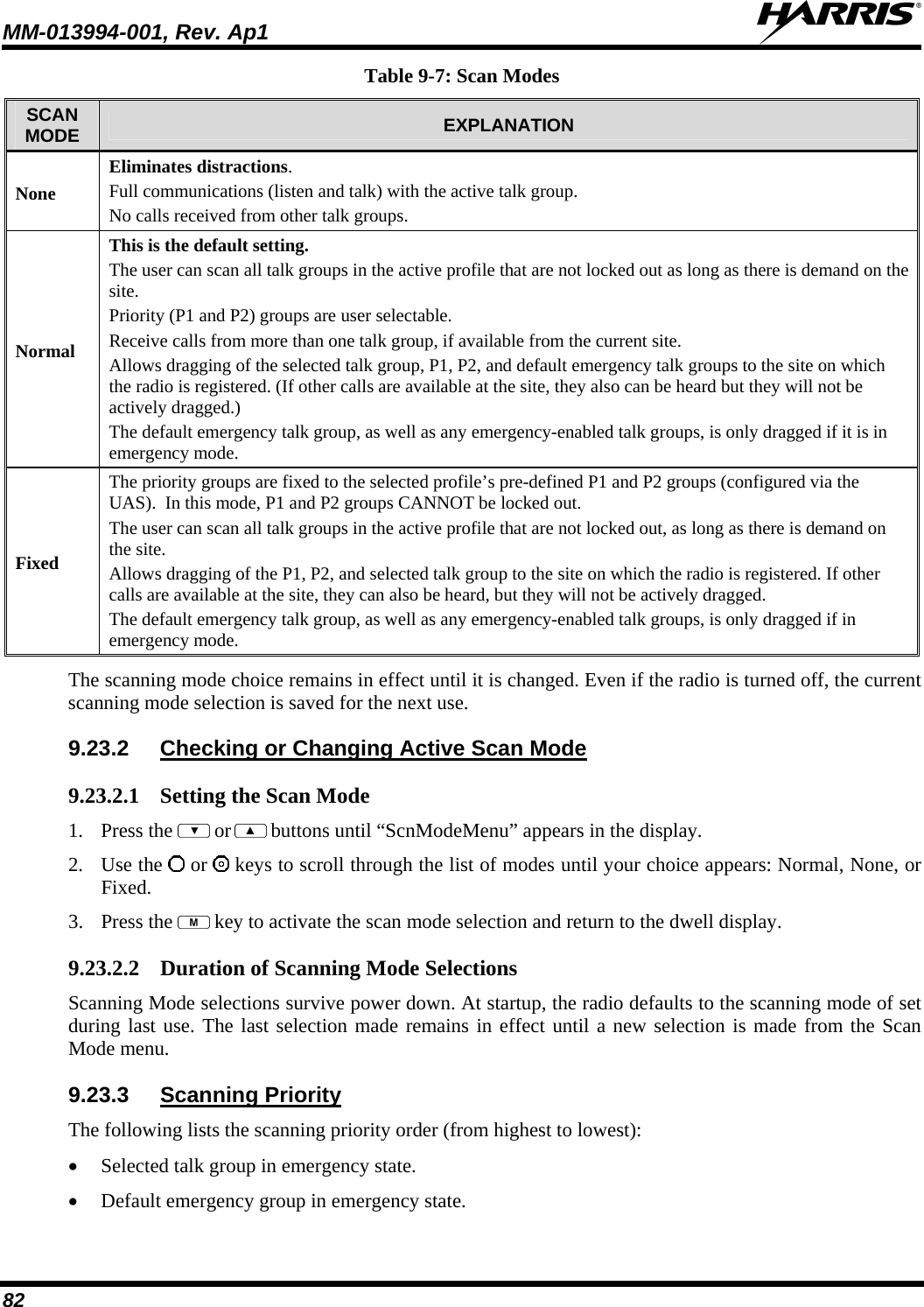
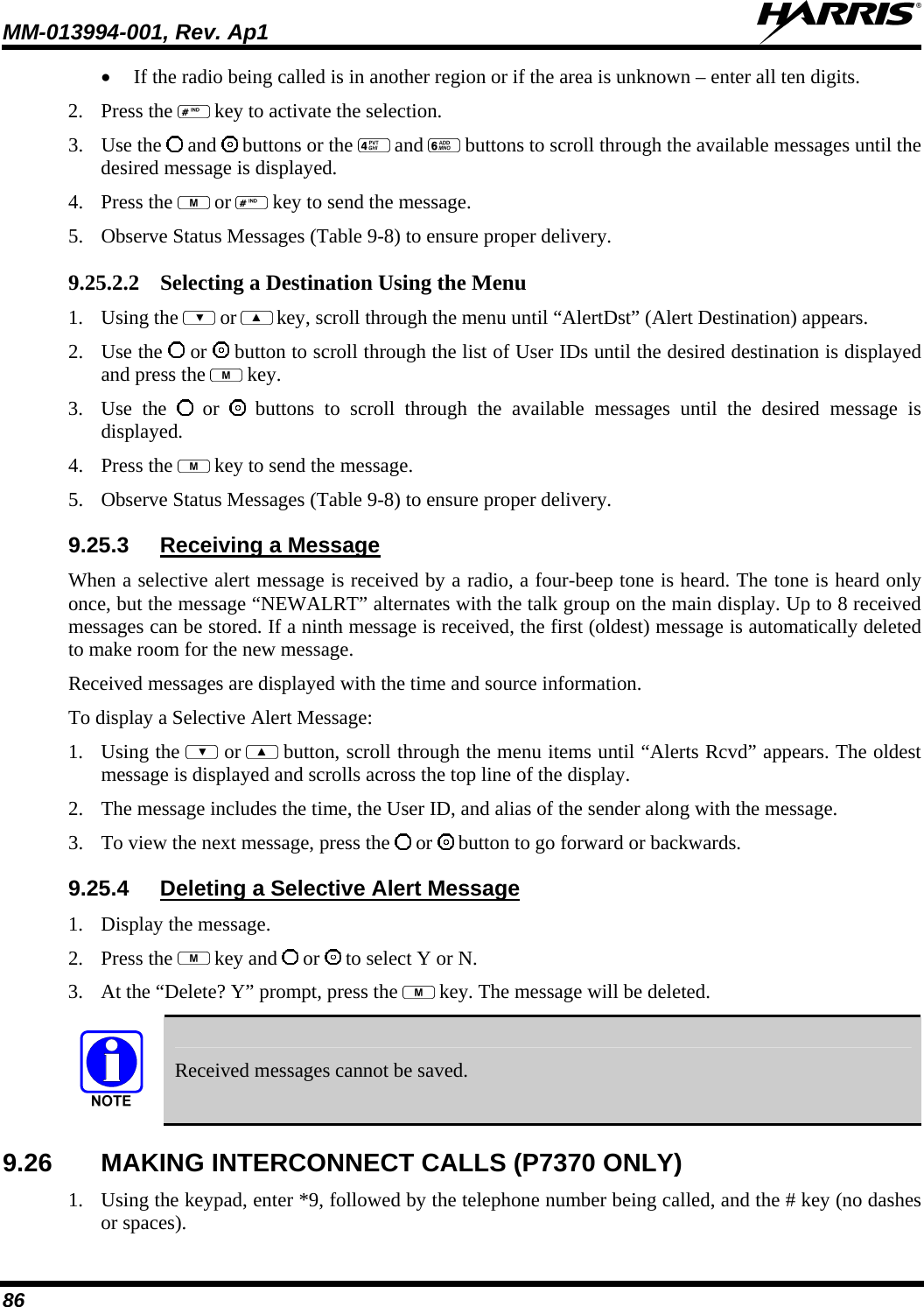
![MM-013994-001, Rev. Ap1 74 9.9 BASIC MENU STRUCTURE Table 9-4 illustrates the basic P7300 OpenSky menu structure. Menu items will vary depending upon system programming, radio hardware, and optional configurations. All menus except the dwell display menu can be turned off by network administration personnel. Table 9-4: Basic P7300 OpenSky Menu Structure Menu Name Radio Displays (first and second lines) Usage Notes To/From Dwell Display registration, RF sync and transceiver status codes Engineering Display (Menu may not be available per programming.) bit-error rates and RSSI data Displays radio system connection data. For engineering use. OFF/ON Silent Emergency “SilentEmerg” Use or to toggle between OFF/ON. Press to enable. available modes Operating Mode (e.g., OTP, OCF) “Mode Menu” Use or to choose an available mode. Press and confirm (Y/N) with or and again. current latitude and longitude (degrees:minutes:seconds) GPS Fix [e.g., GPS, GPS (Site), GPS (Aged)] “GPS” GPS latitude and longitude position of currently tuned-to base station [“GPS (Site)”] or V-TAC (“GPS”) scrolls across top line of the display. “GPS (Aged)” indicates VTAC coordinates haven’t been updated for more that 2 minutes. User ID # of user currently logged in User ID “User ID” User’s identification/name scrolls across top line of the display (if programmed). Radio’s IP address IP Address “IP Address” Radio’s Internet Protocol (IP) address scrolls across top line of the display. station’s call sign Station Identification “Station ID” Station’s identification/name scrolls across top line of the display (if programmed). “OFF” Stealth Mode (display backlight is disabled) “StealthMenu” Use or to turn on. On P7350, press any button to turn it off. On P7370, use Stealth Menu or press 2# to disable 2# to disable Stealth mode. “LOW”, “MEDIUM”, “MEDHIGH”, “HIGH” Treble Level “Treble Menu” Use or to choose speaker treble level. Press to return to dwell display. “<< >>” Display Brightness “Bright Menu” Use or to brighten or dim backlighting. Press to return to dwell display. “OFF”, “LOW”, “MED”, HIGH” Side Tone Level “Side Menu” Use or to choose side tone level. Press to return to dwell display. See Next Page](https://usermanual.wiki/HARRIS/TR-0054-E/User-Guide-1132261-Page-75.png)
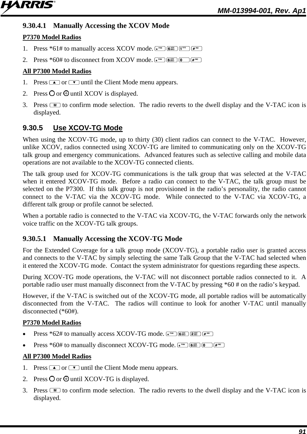
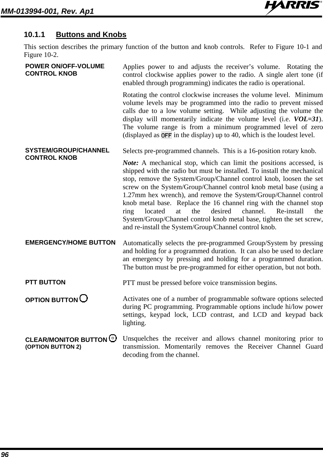
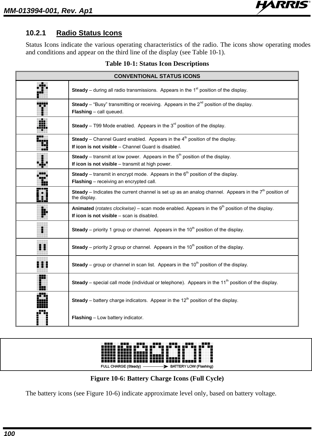
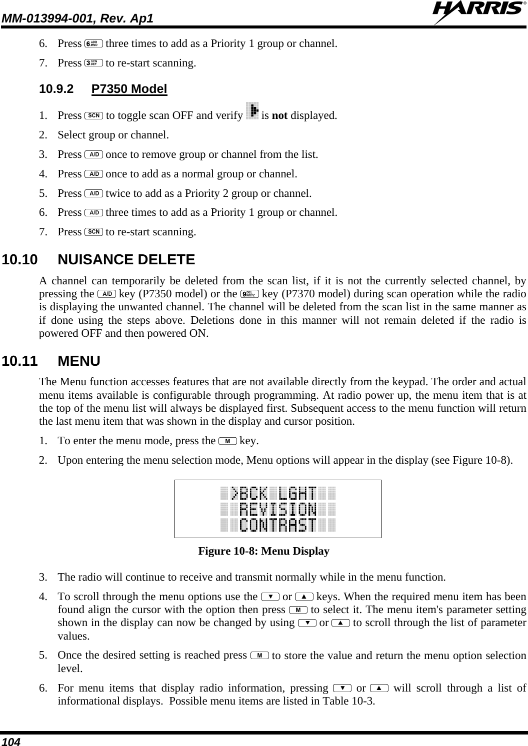
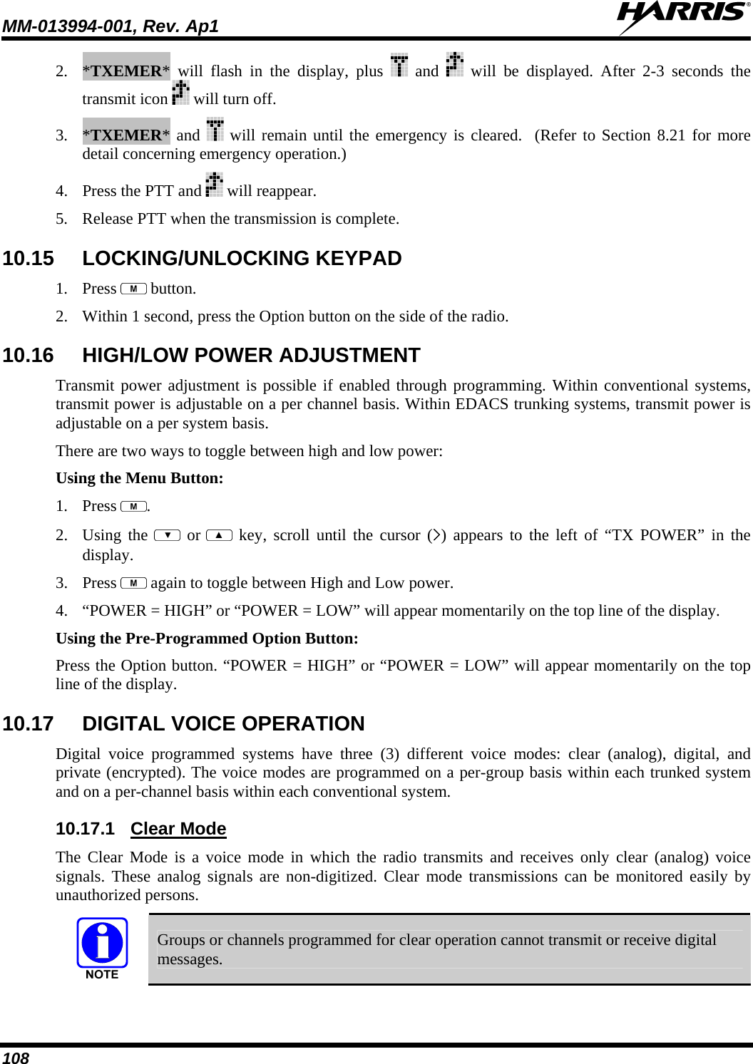
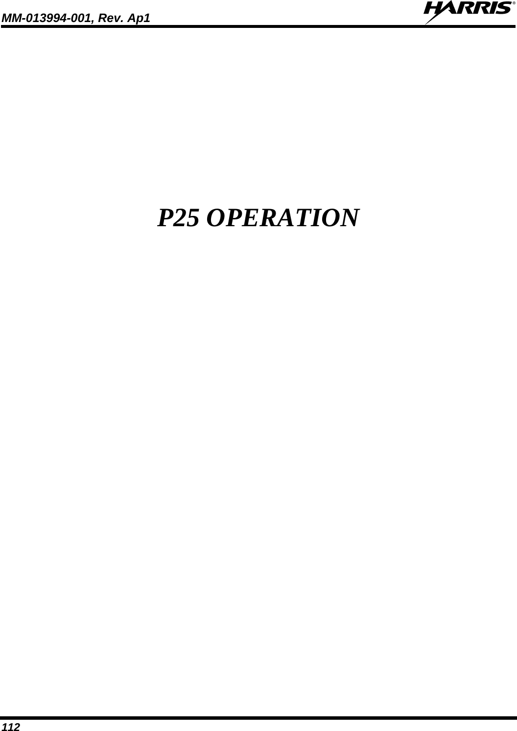
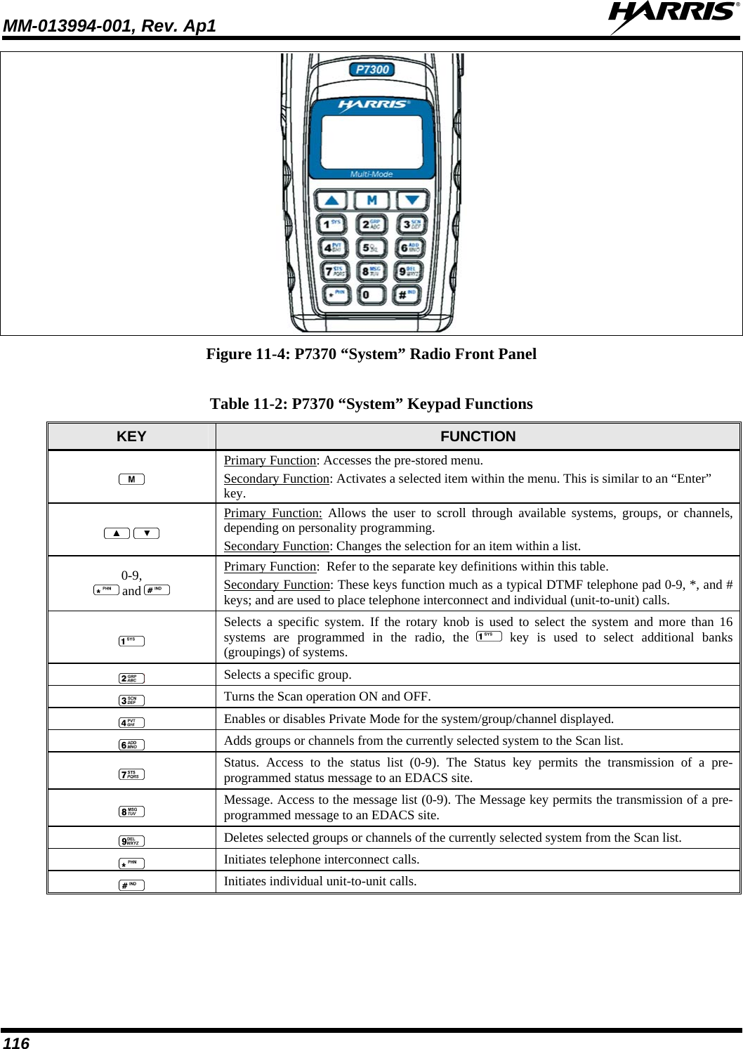
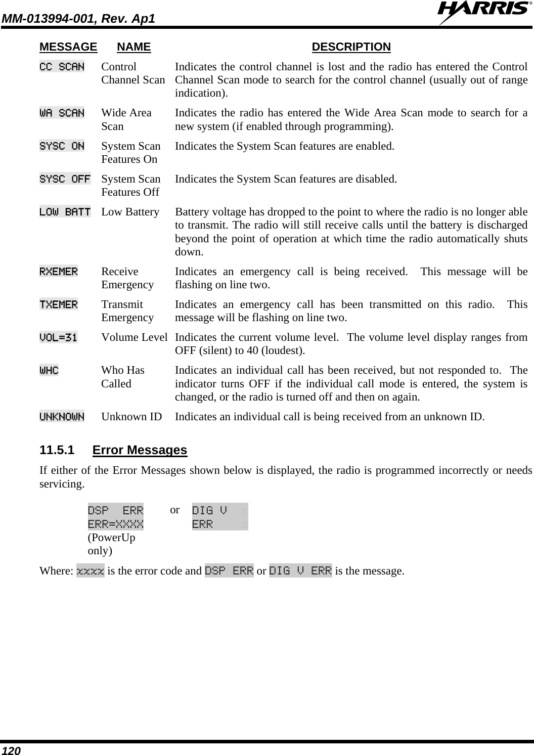
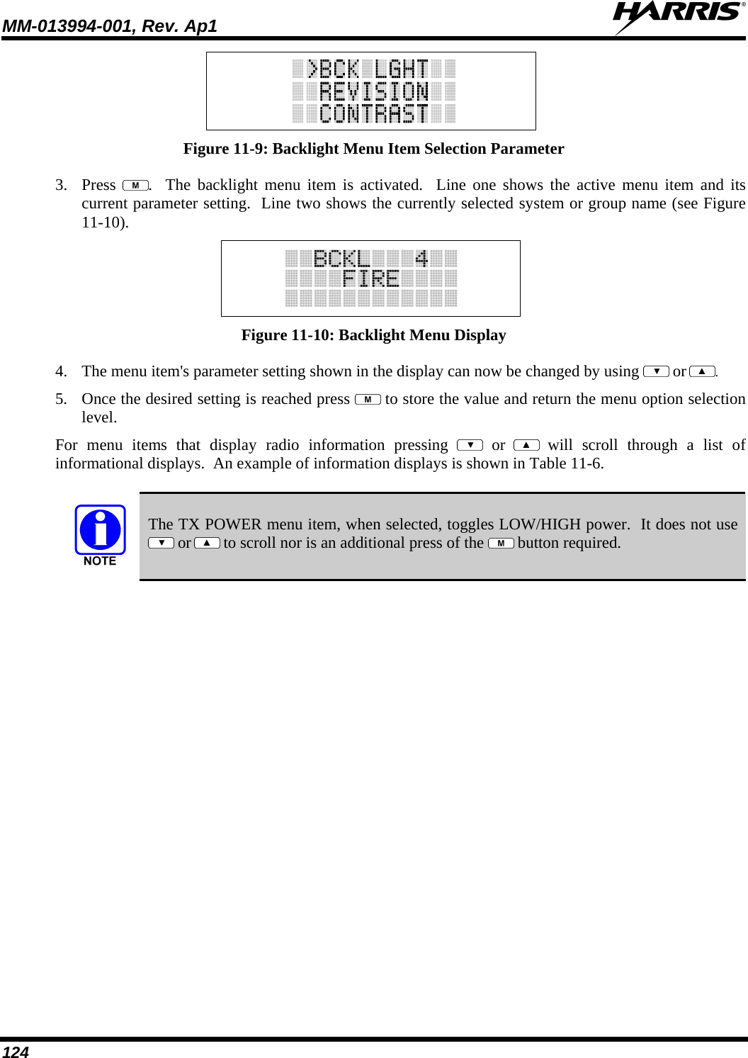
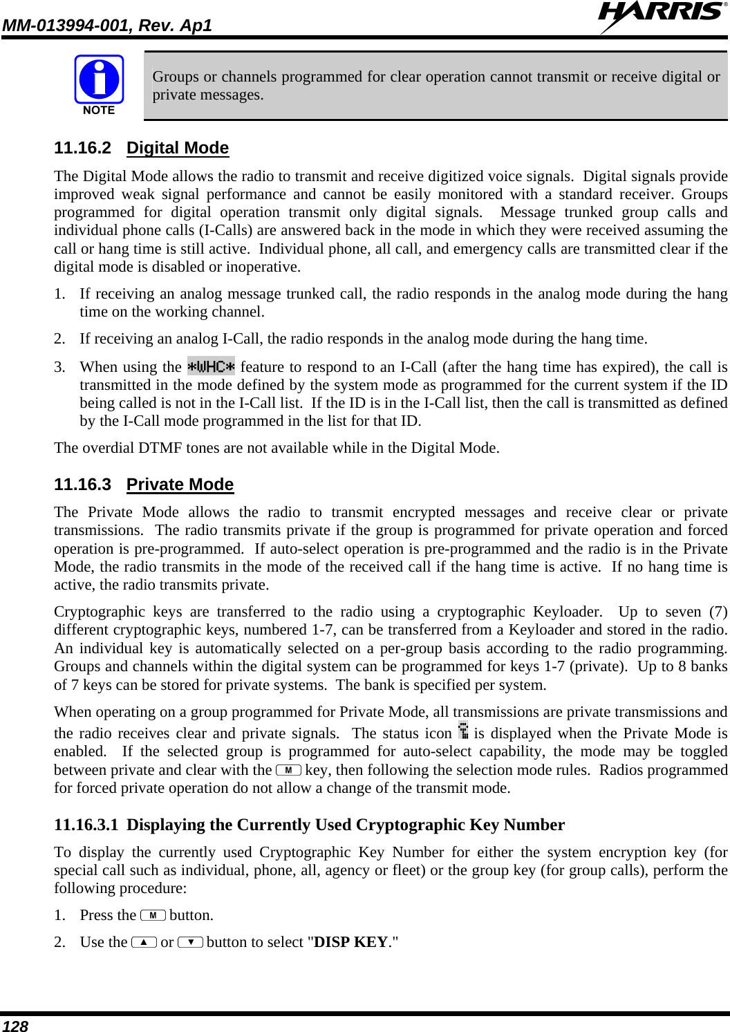
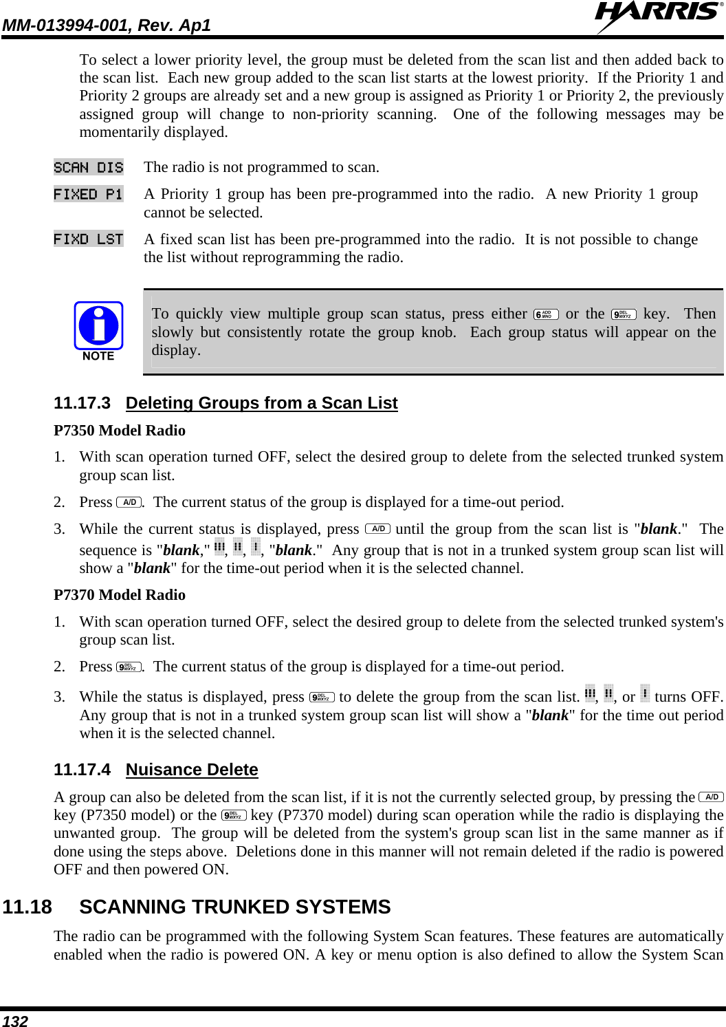
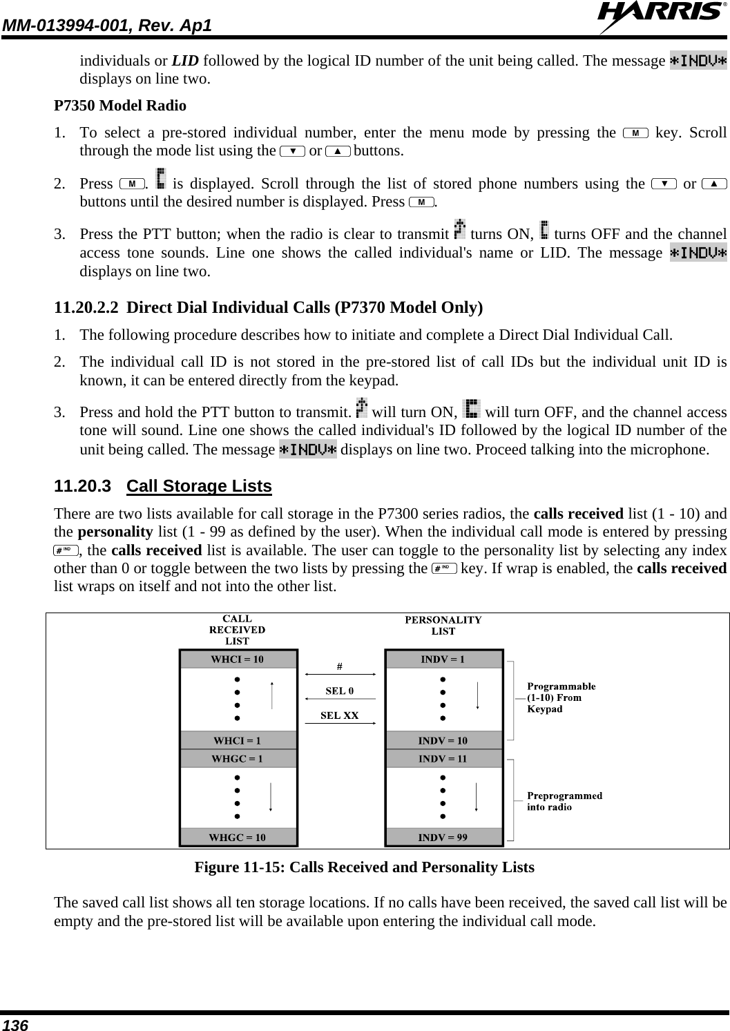
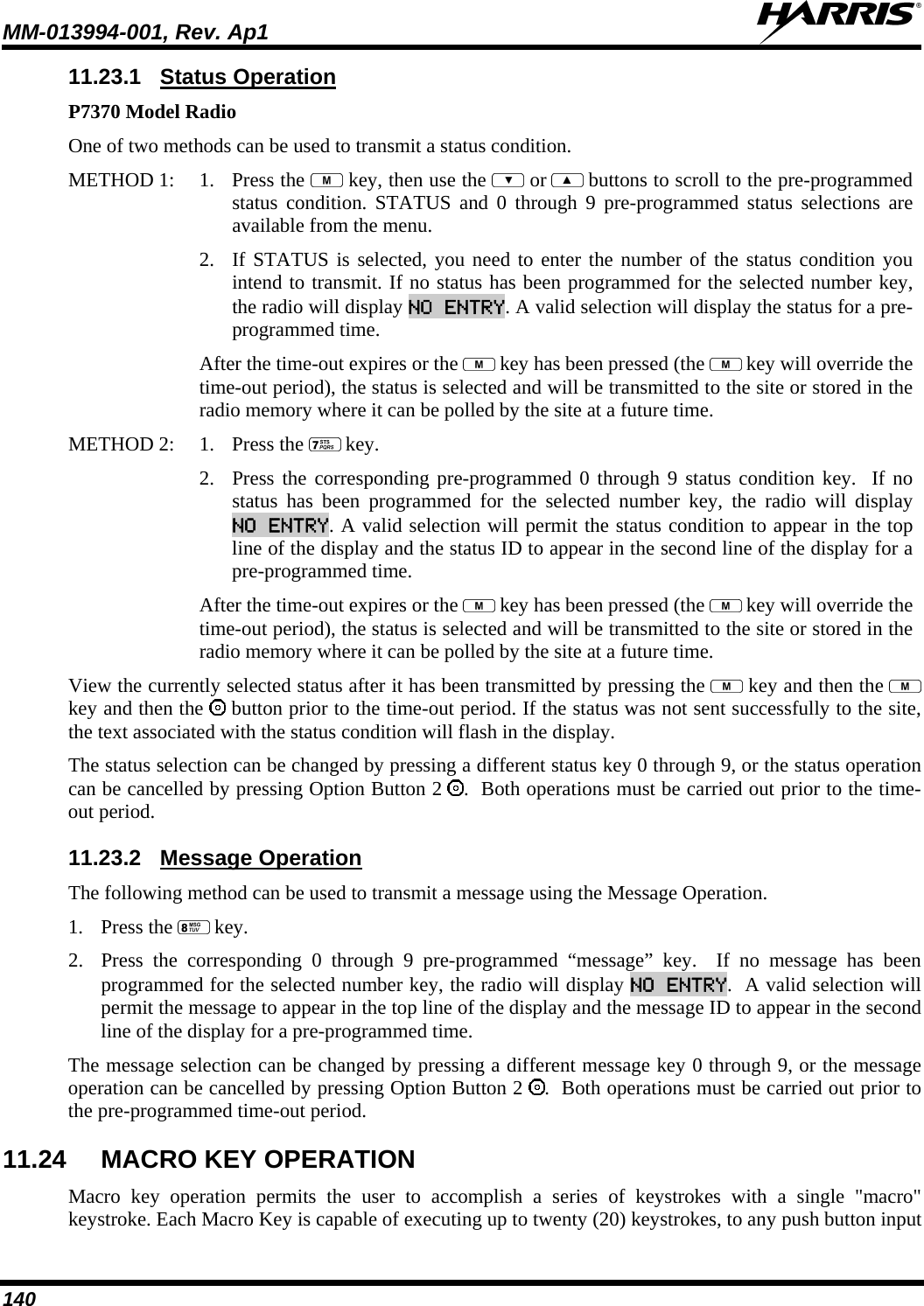
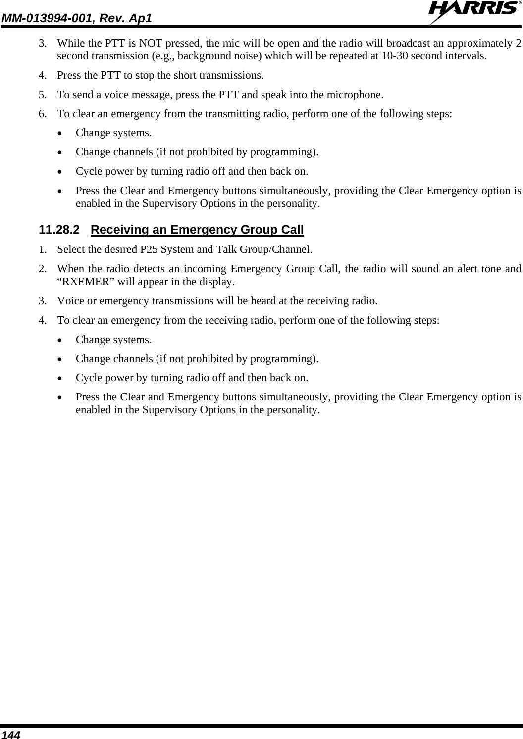
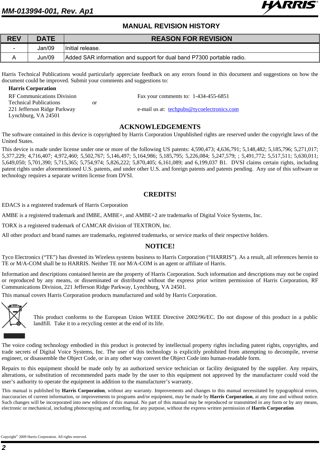
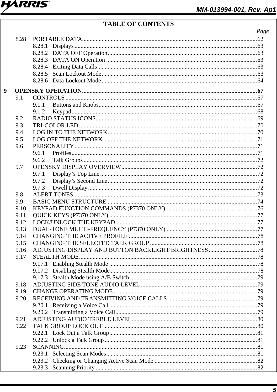
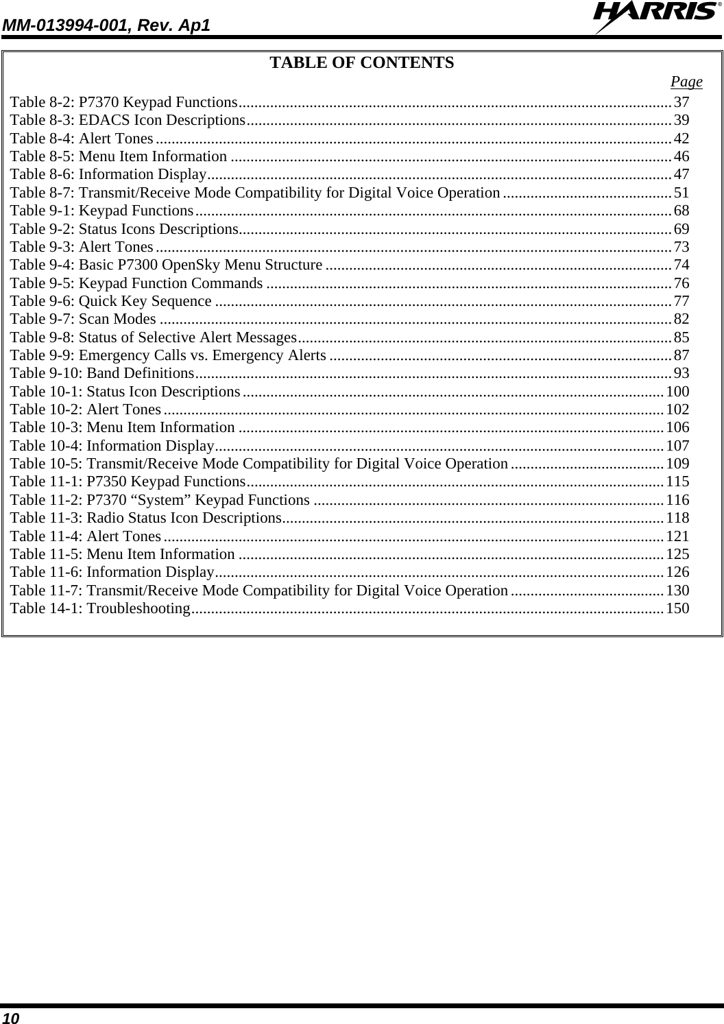
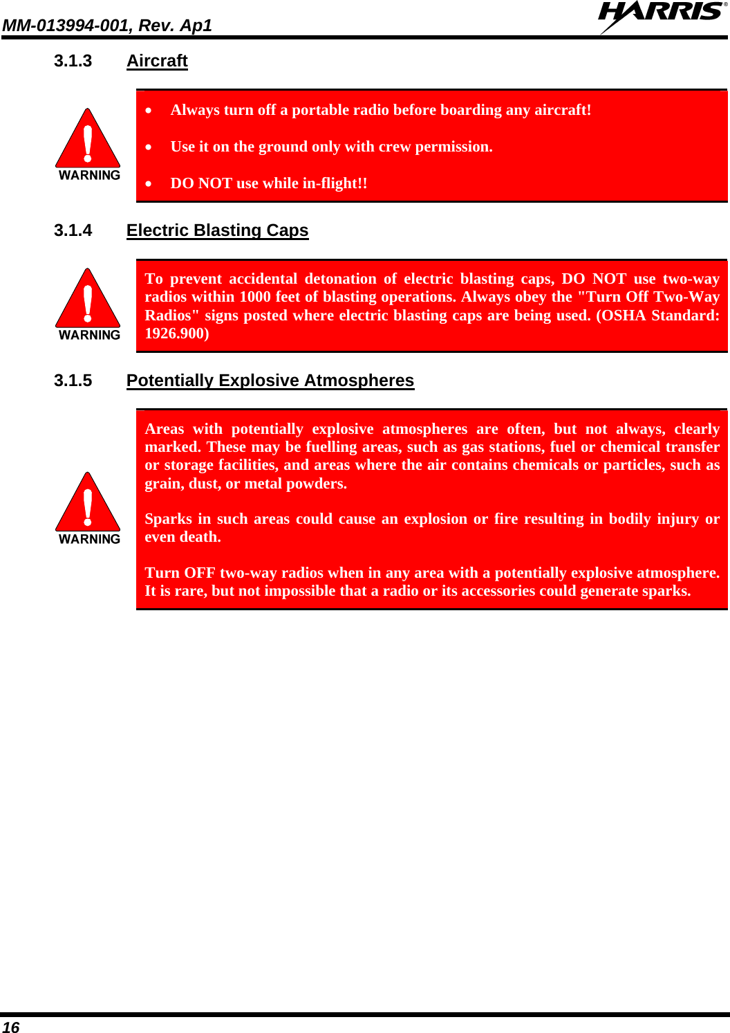
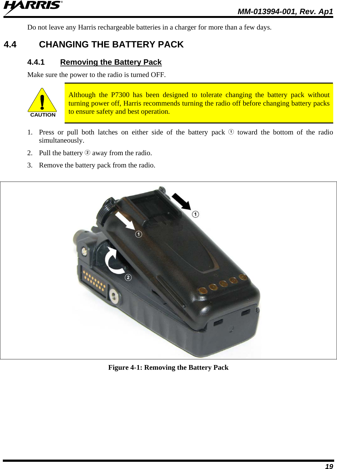
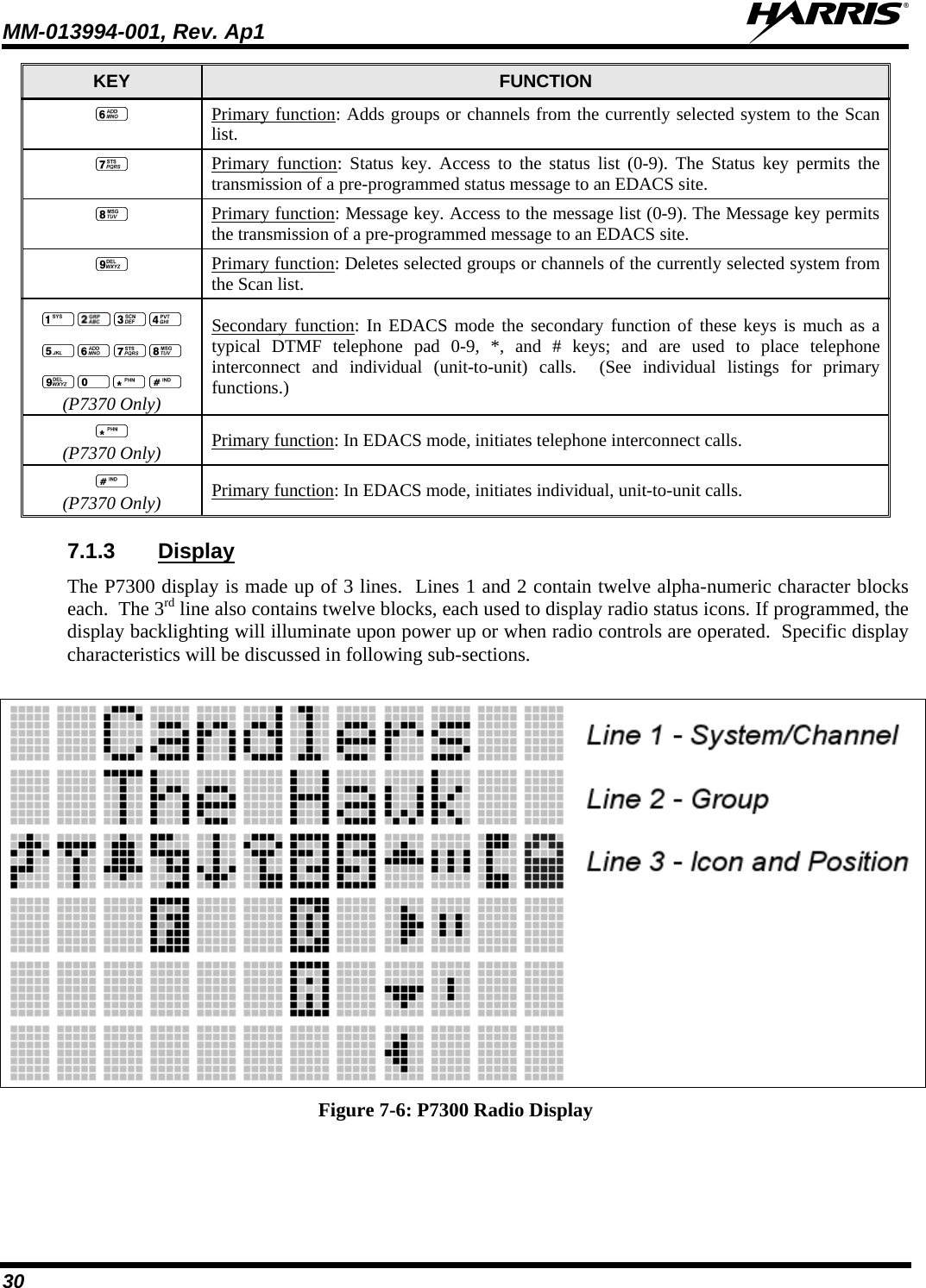
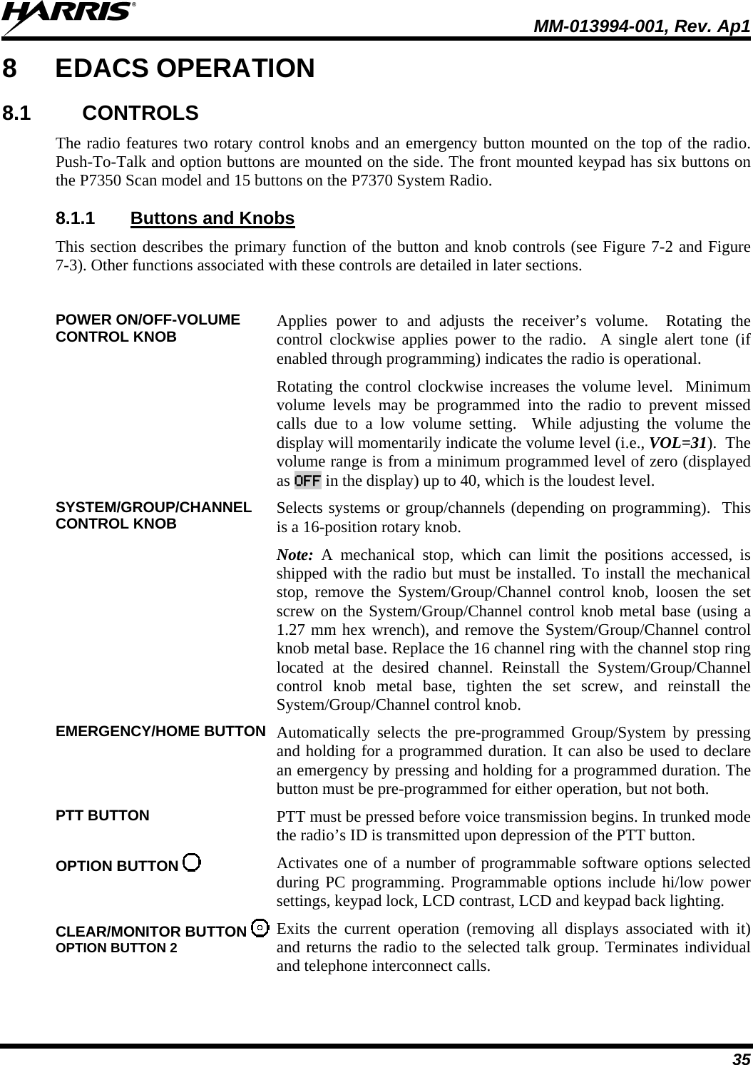
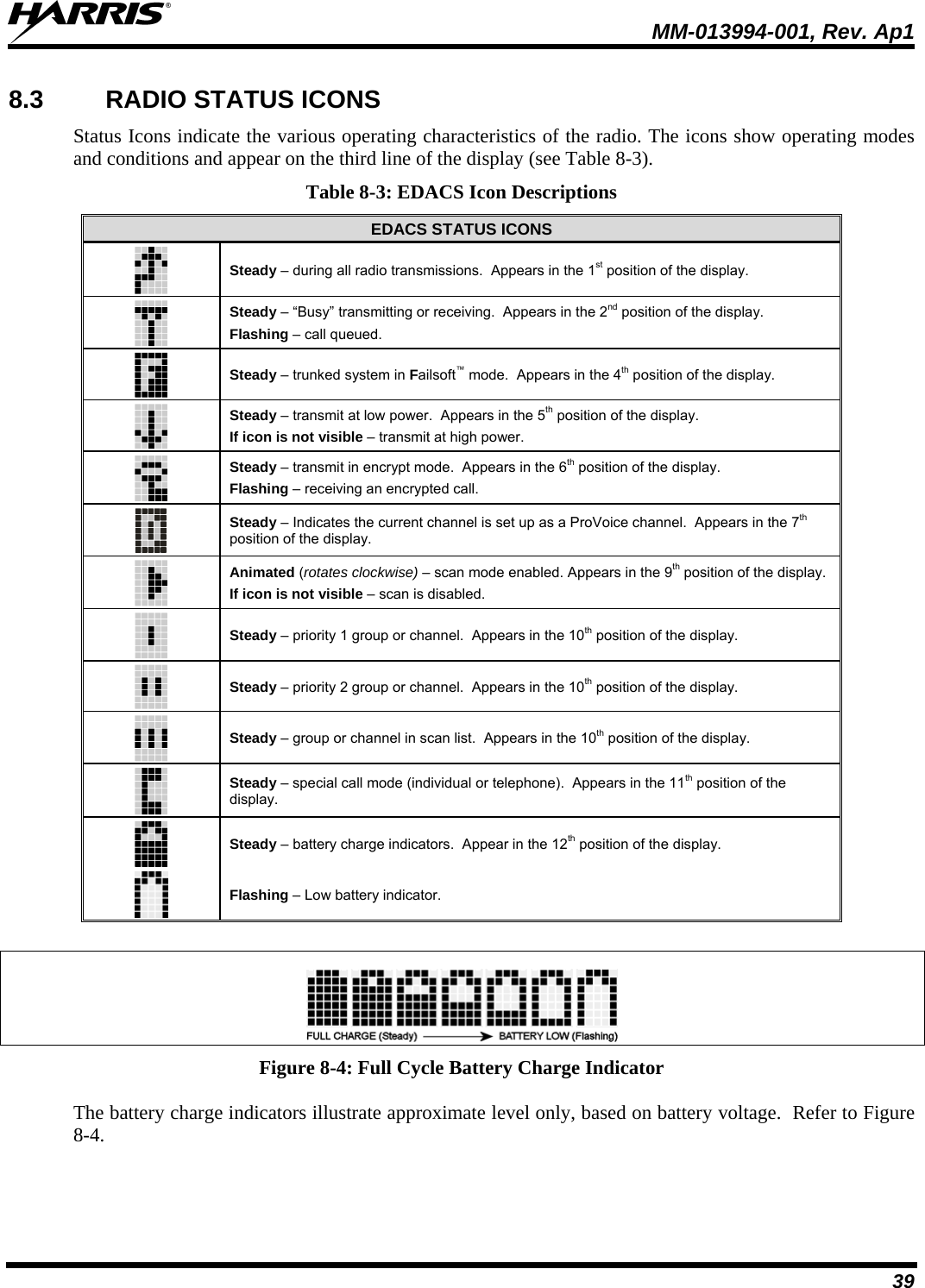
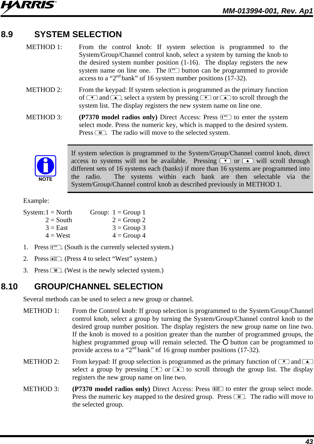
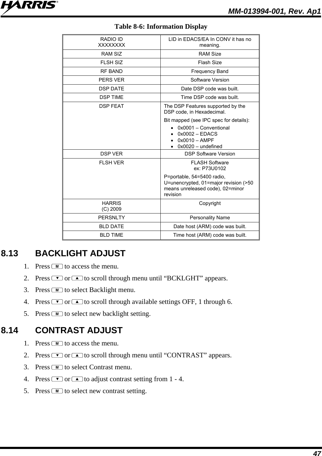
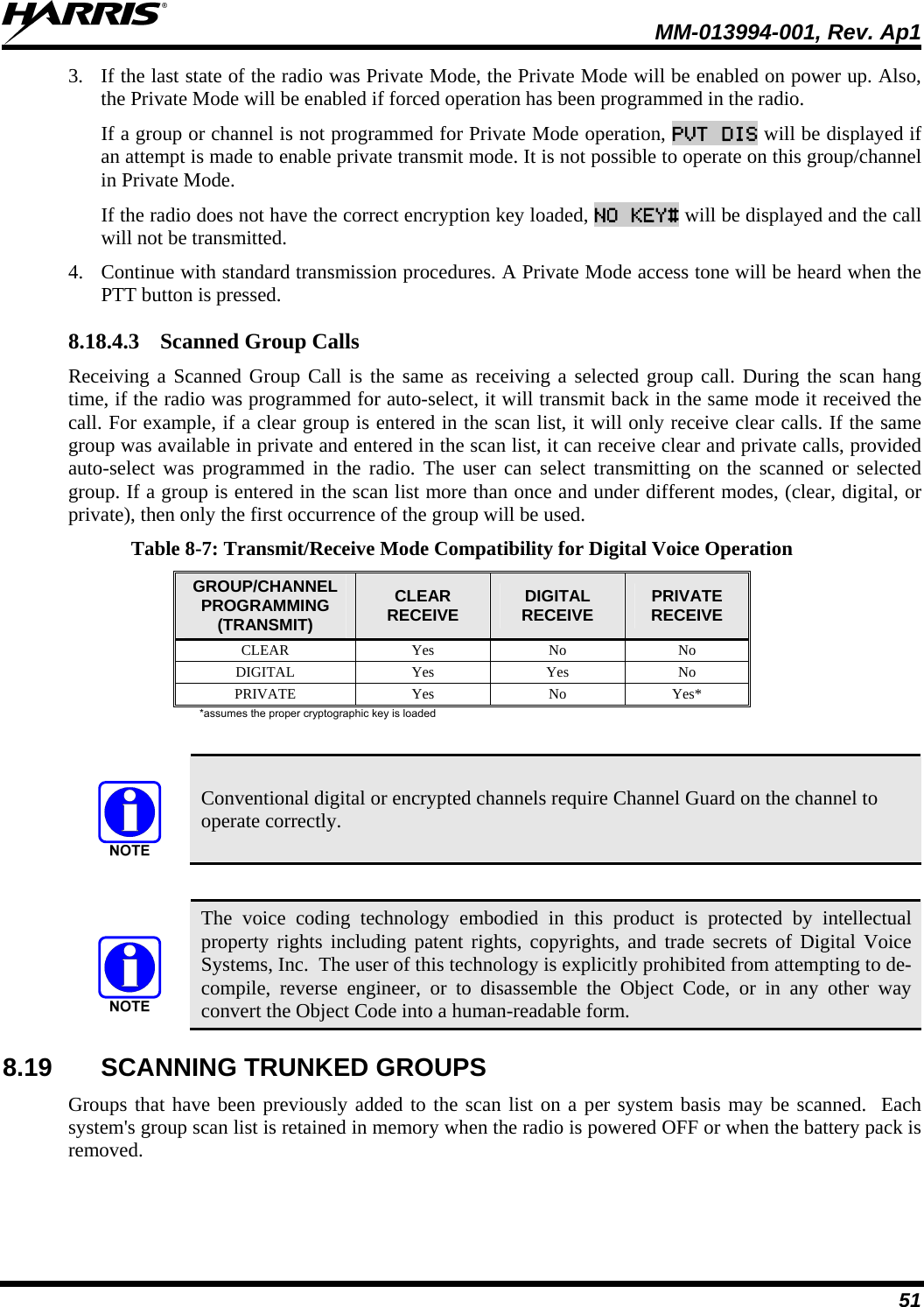
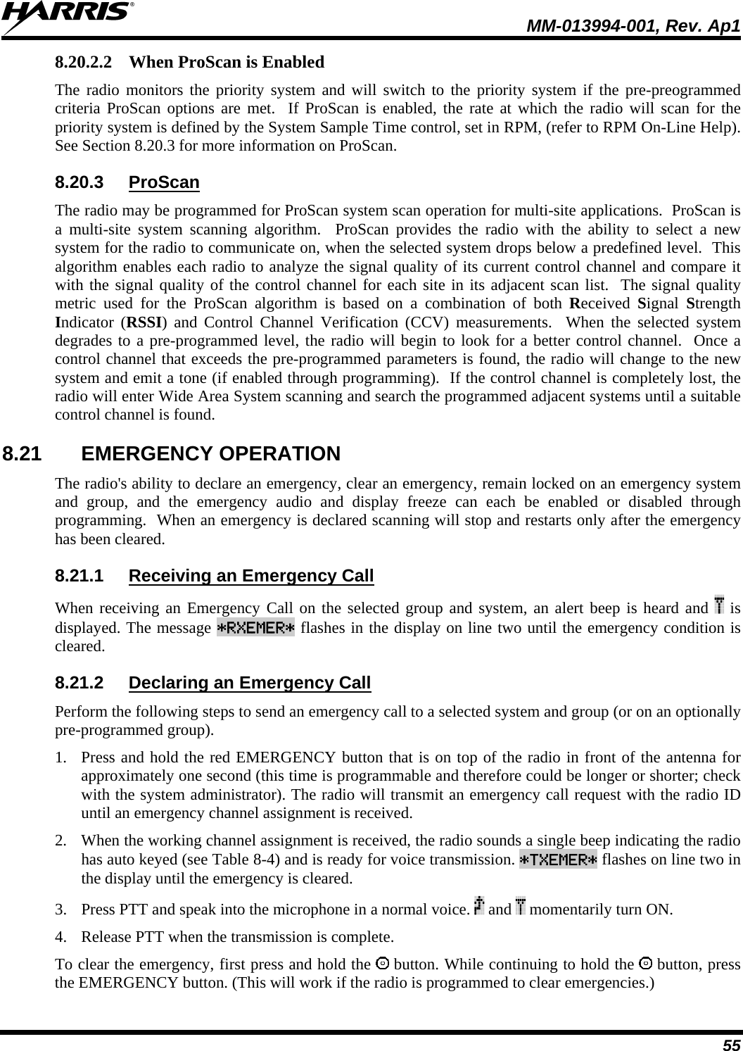
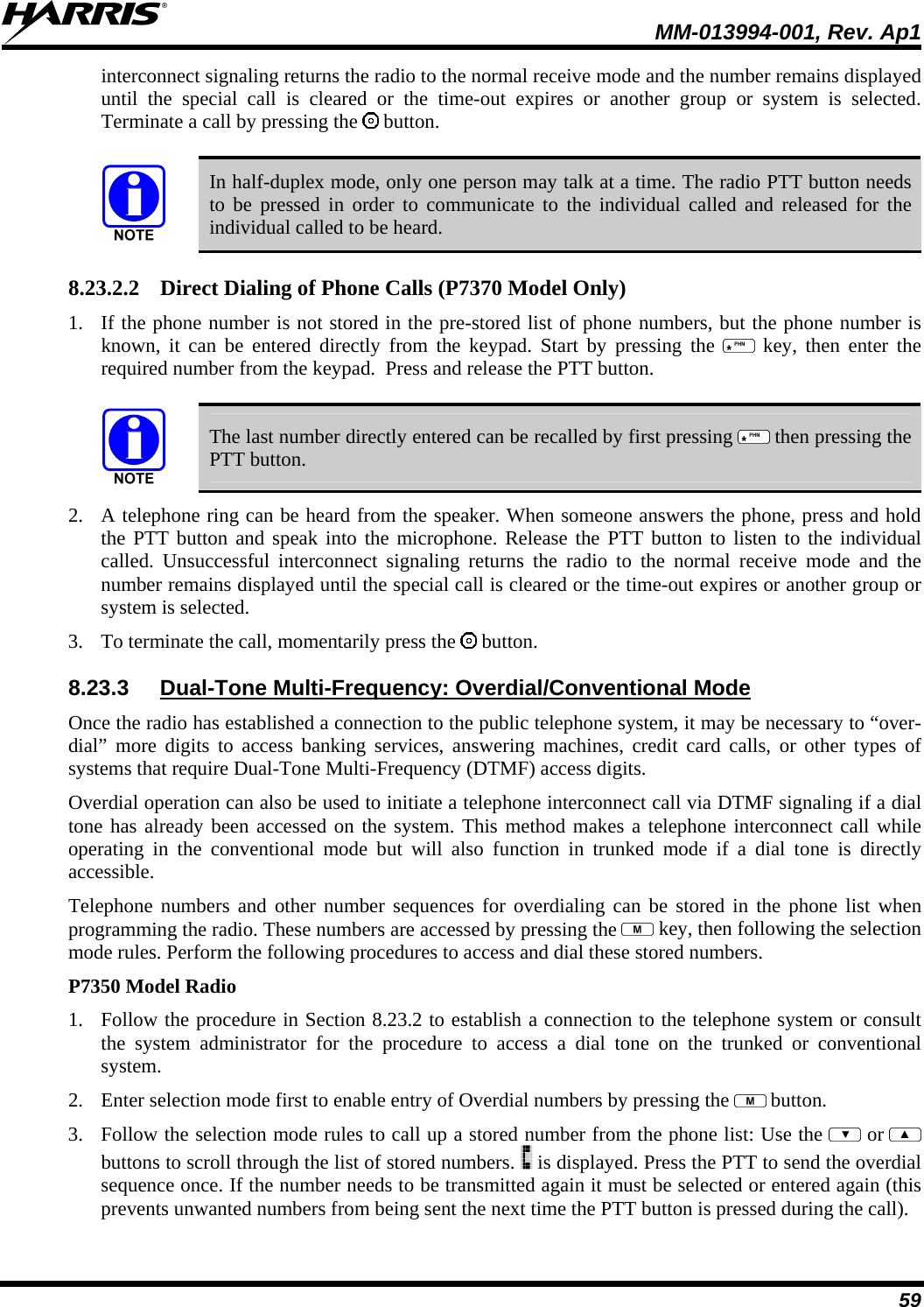
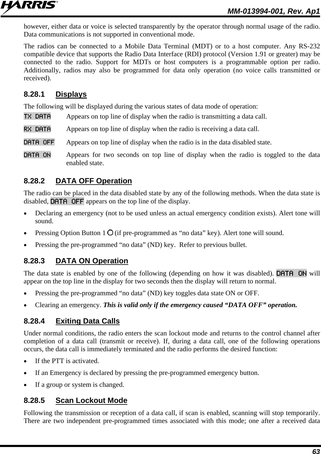
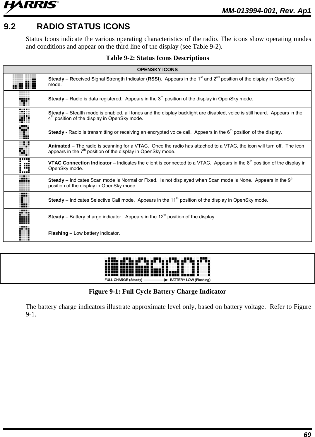
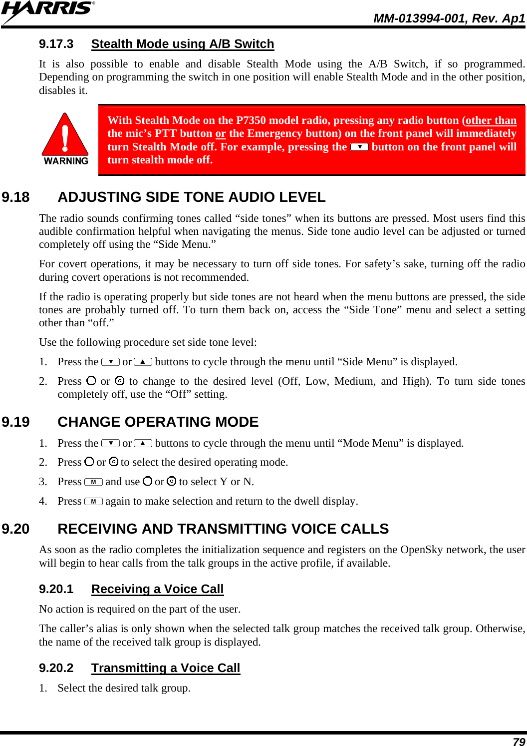
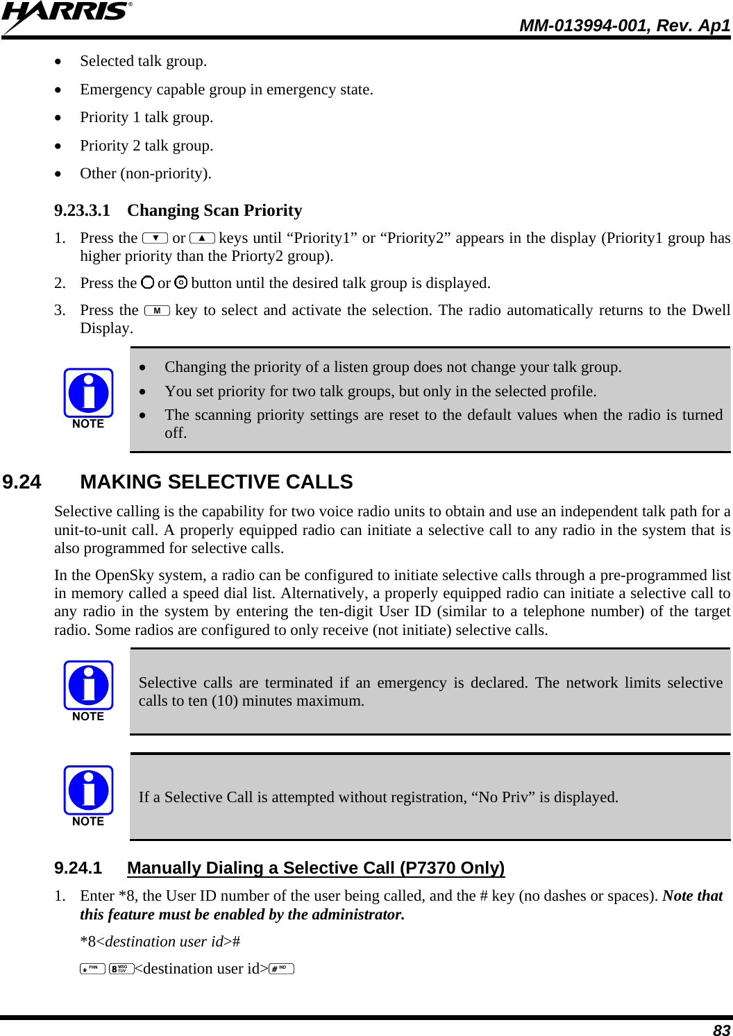
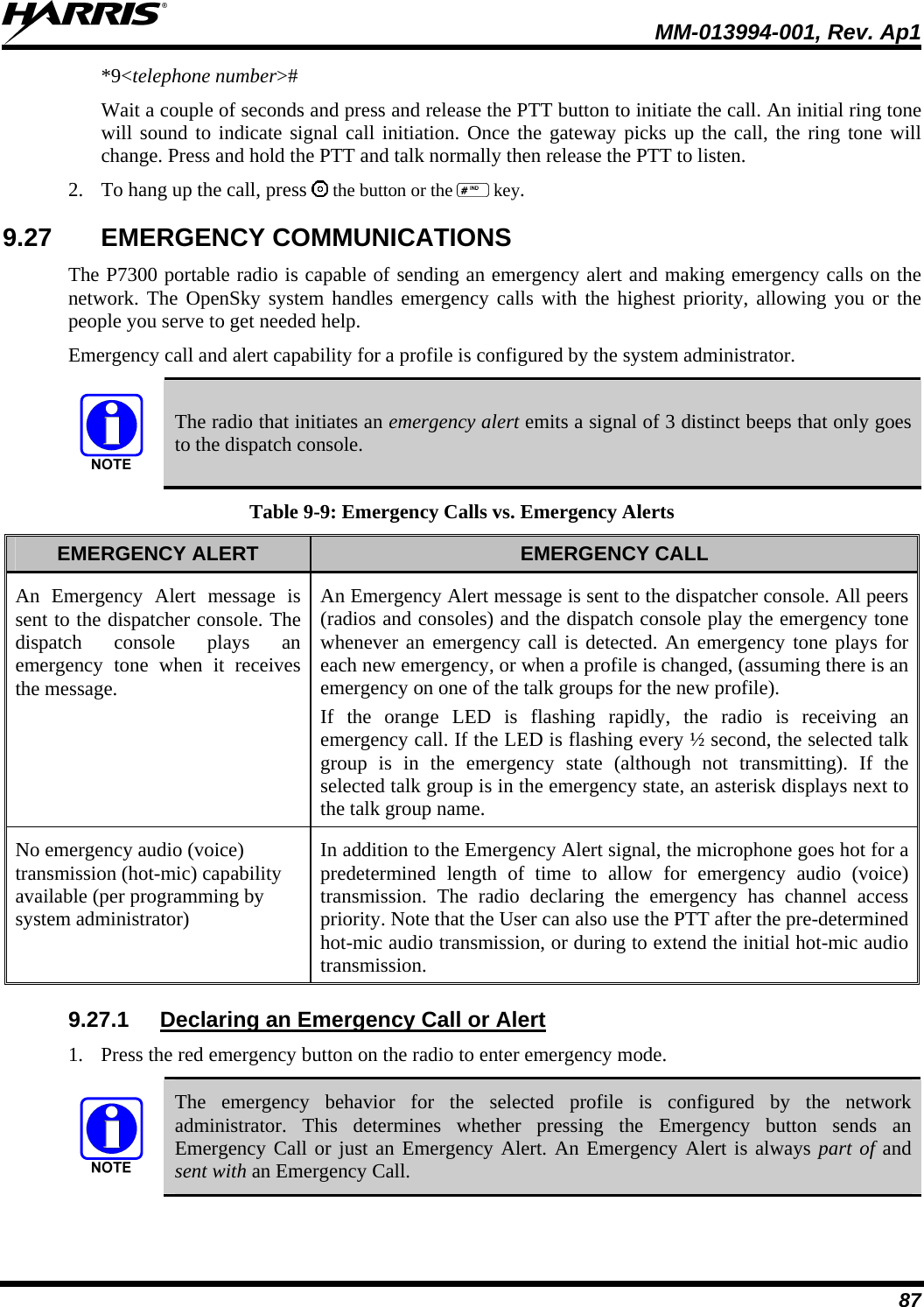
![MM-013994-001, Rev. Ap1 76 9.10 KEYPAD FUNCTION COMMANDS (P7370 ONLY) To perform a command from the keypad, use the keypad commands in Table 9-5. Table 9-5: Keypad Function Commands *0 Log-off command: *0## (logs the user off the system). See Section 9.5 for additional information. Key presses: *1 Log-in command: *1<User ID> # <Password> ## (required for encryption). See Section 9.2 for additional information. Key presses: <User ID> <Password> *4 Enter Scene of Incident Mode (SOI) on specified channel and band: *4<LC>#<Band># where LC is the channel number that is being used as a SOI repeater and band is the number assigned to each frequency band. For example, if LC 25 800 MHz (band 0) is being used for SOI, then enter *4,25,#,0,#. Exit SOI Mode with *4# Key presses: *6 Go to Default Profile. Selects default profile if the radio is not voice registered. *7 Initiate Selective Alert command: *7<Target ID>#[Choose Message]#. See Section 9.25 for additional information. Exit SOI Mode with *4#. Command: *8 Radio-to-Radio Call command: *8<Selective call number>#(PTT to dial). Command: <Selective call number> then press PTT to dial *9 Public Switched Telephone Network (PSTN) Call command: *9 <telephone number>#(PTT to dial) See Section 9.26 for additional information. Command: <telephone number> then press PTT to dial *32 Begin Manual Encryption command: *32<Pre-determined Encryption Key># 1-16 digit encryption key for 128 bit encryption; 17-32 digit encryption key for 256 bit encryption. *33 End Manual Encryption command: *33# *61 Initiate XCOV Mode: Extended coverage for individual users. *62 Initiate XCOV-TG Mode: Extended coverage for talk groups. *60 Exit XCOV or XCOV-TG Mode: Returns to the normal mode.](https://usermanual.wiki/HARRIS/TR-0054-E/User-Guide-1132261-Page-77.png)
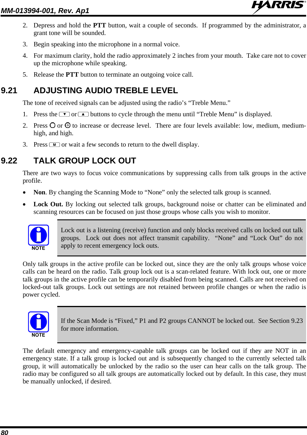
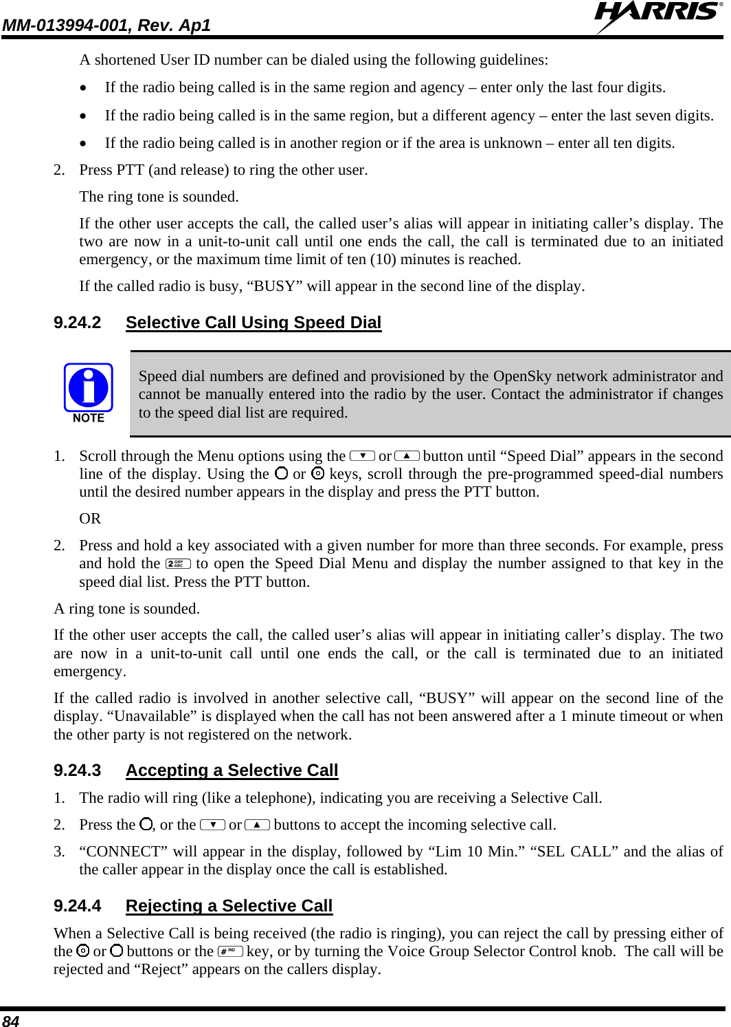
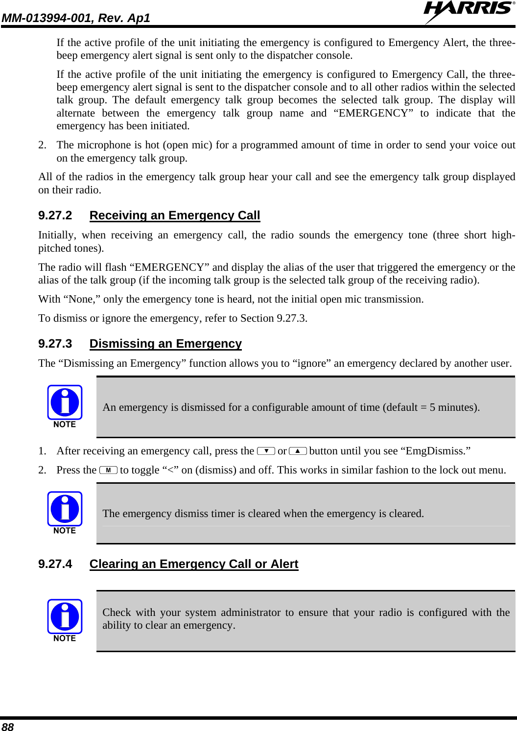
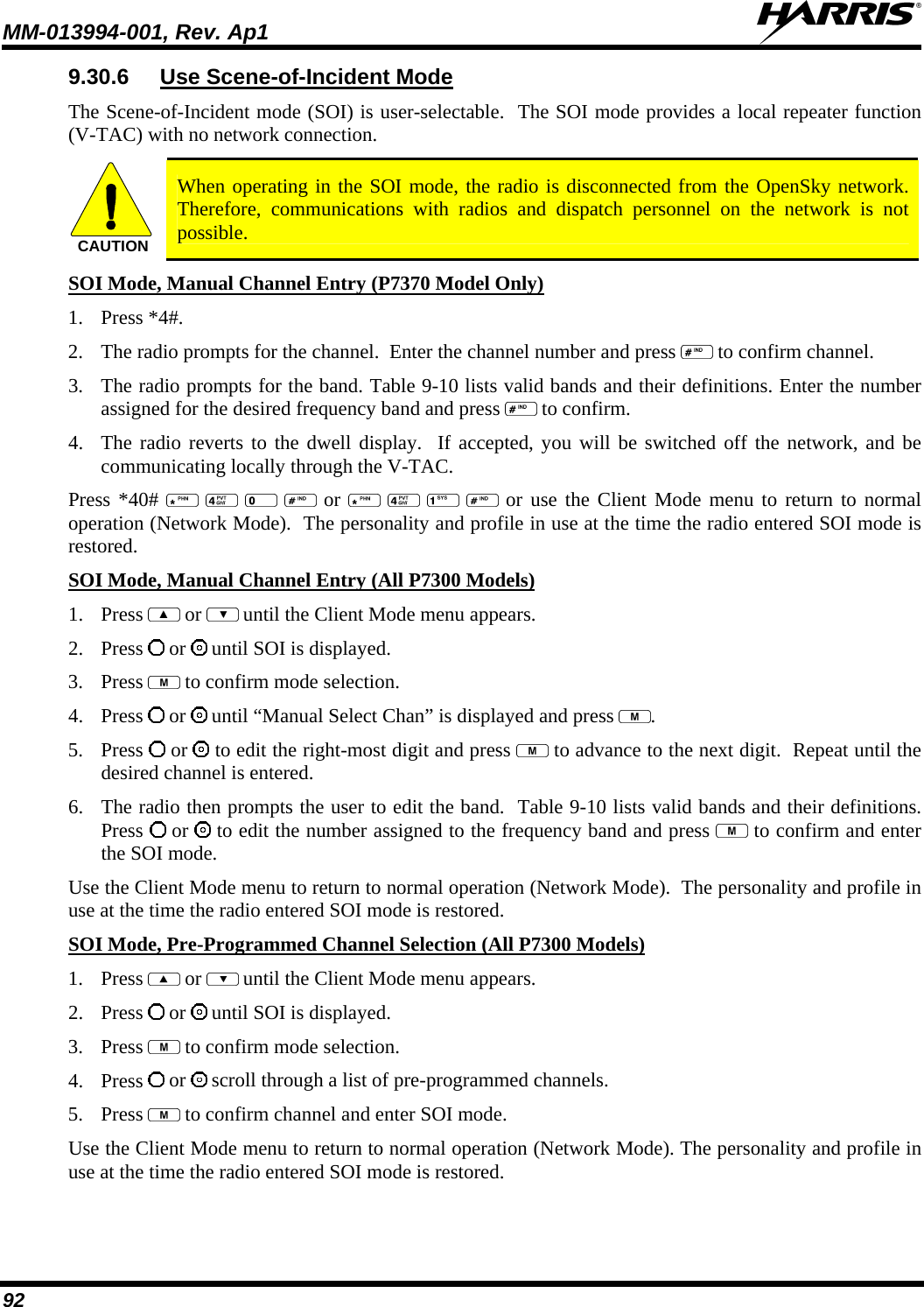
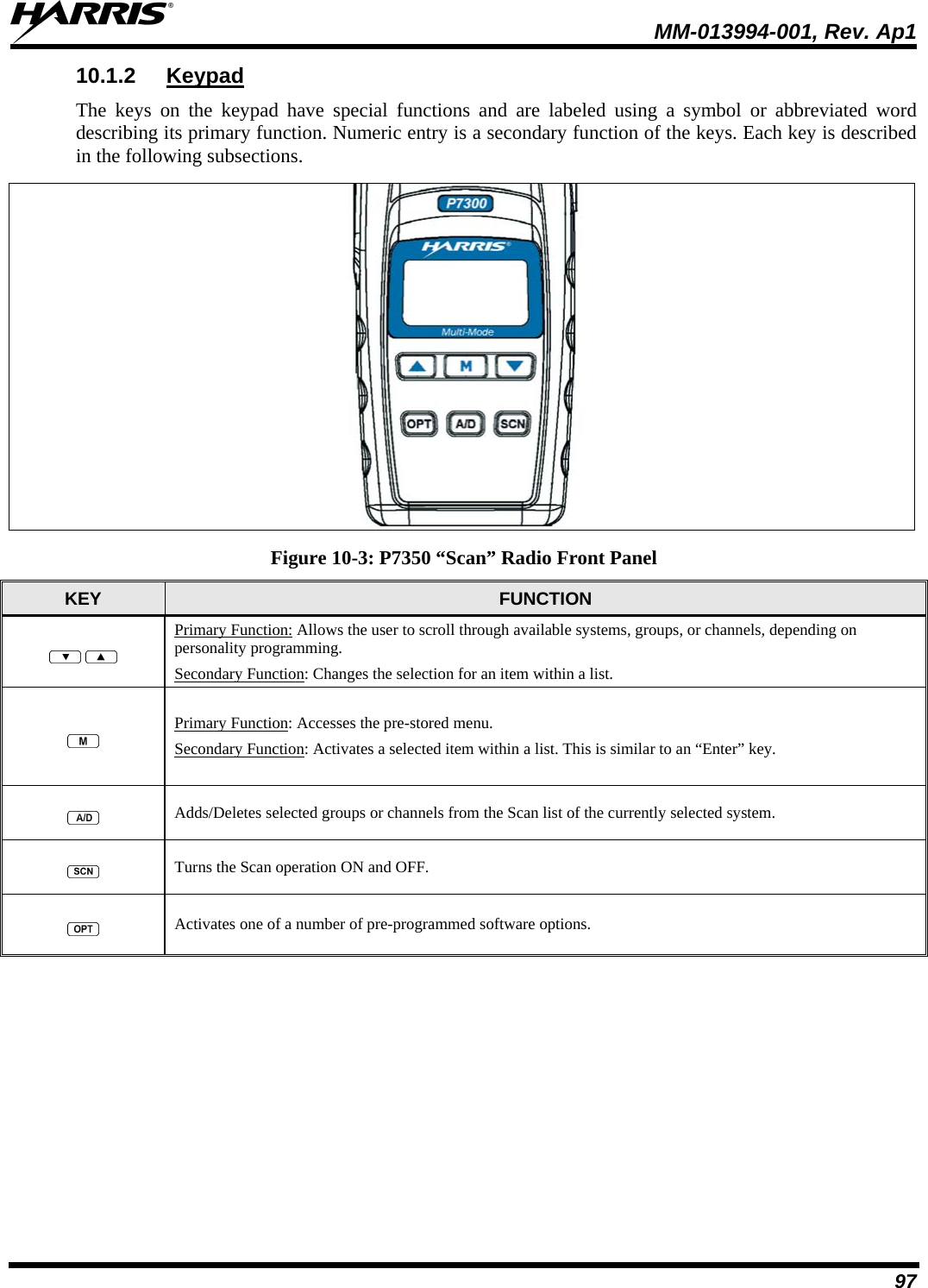
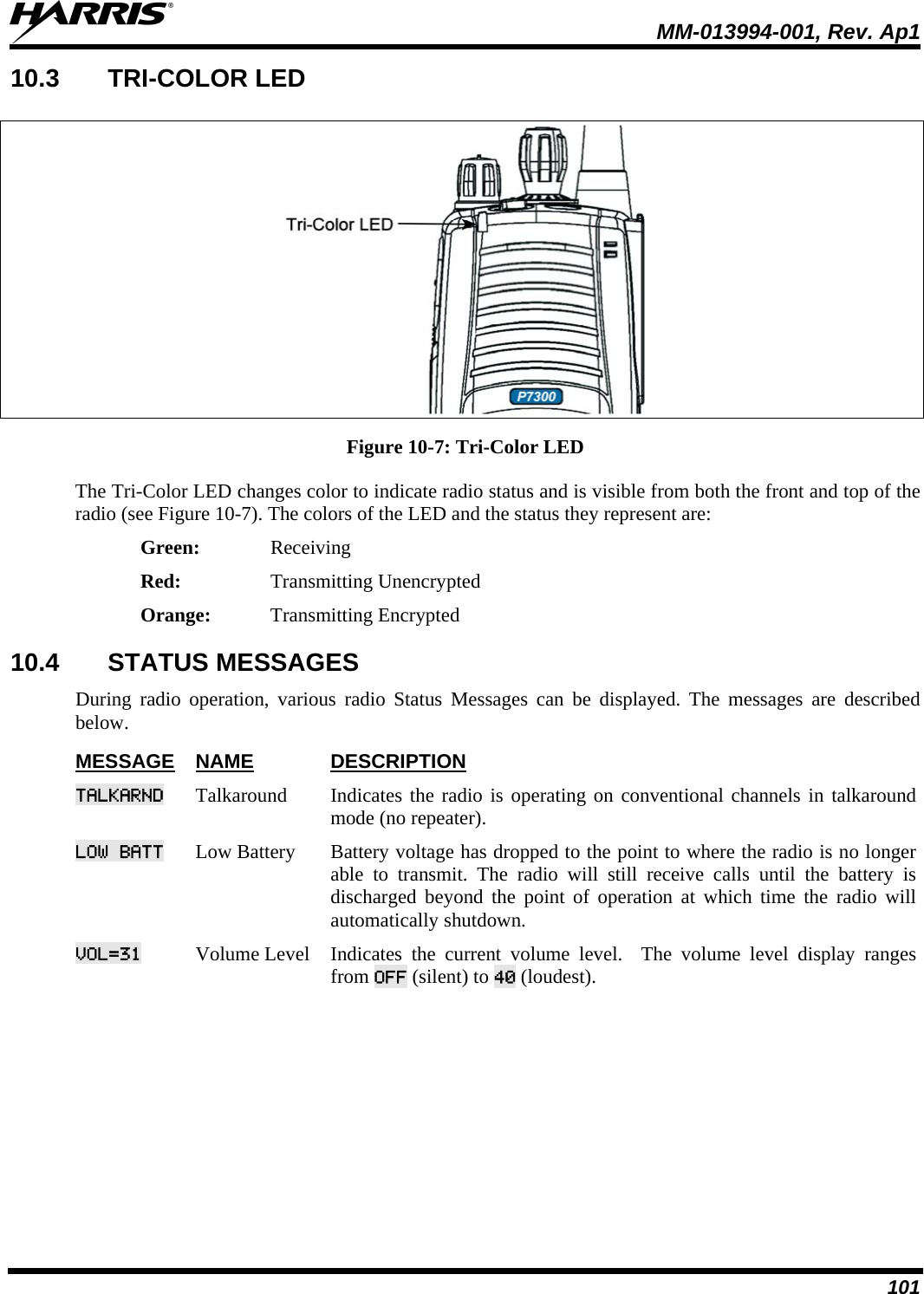
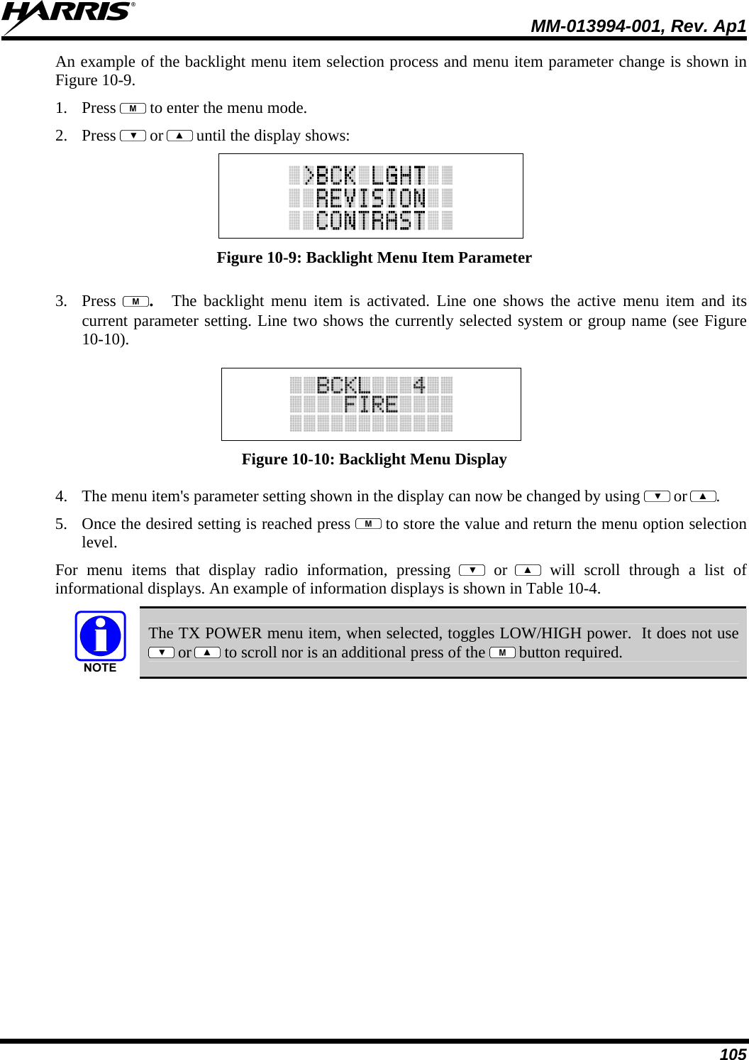
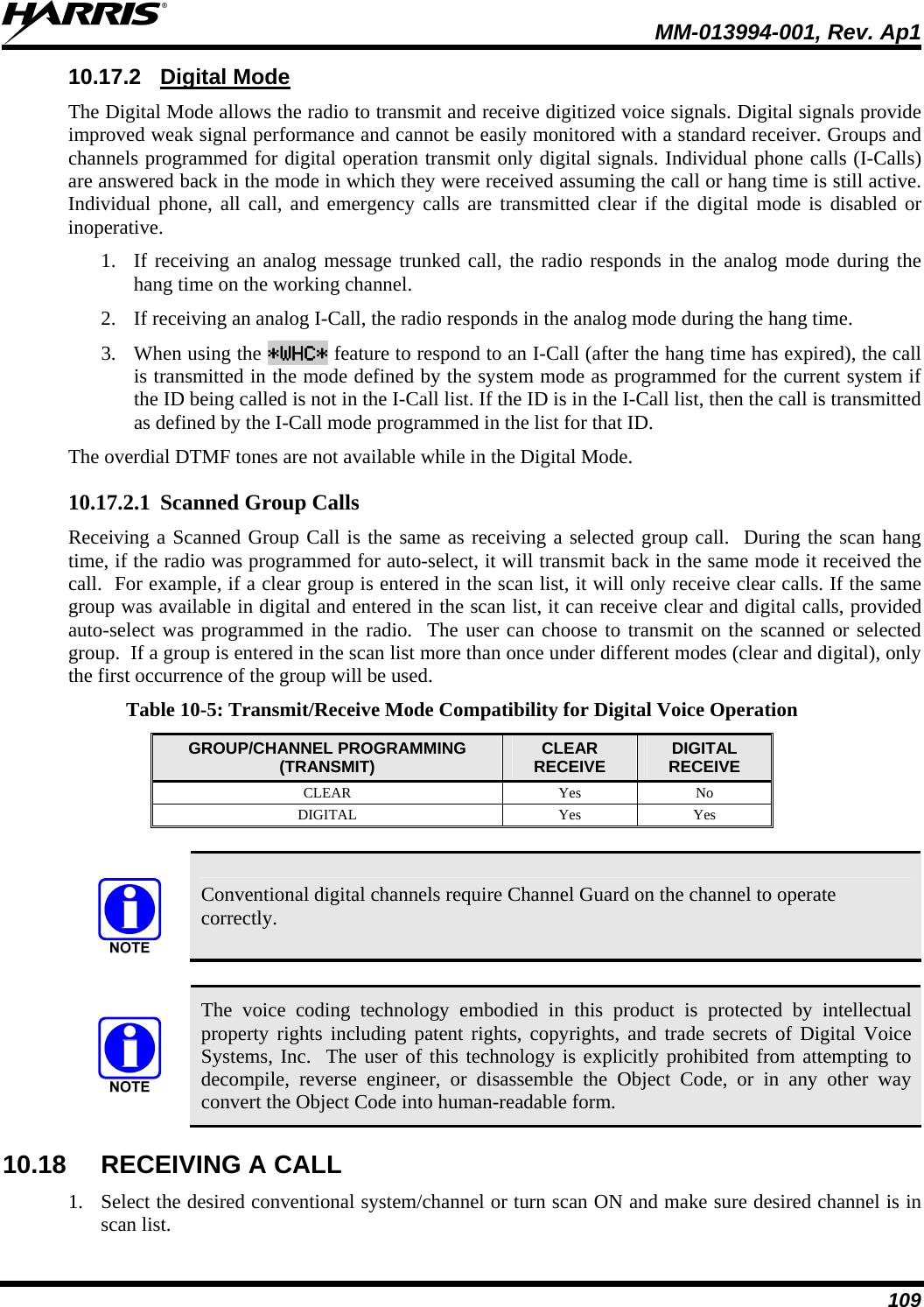
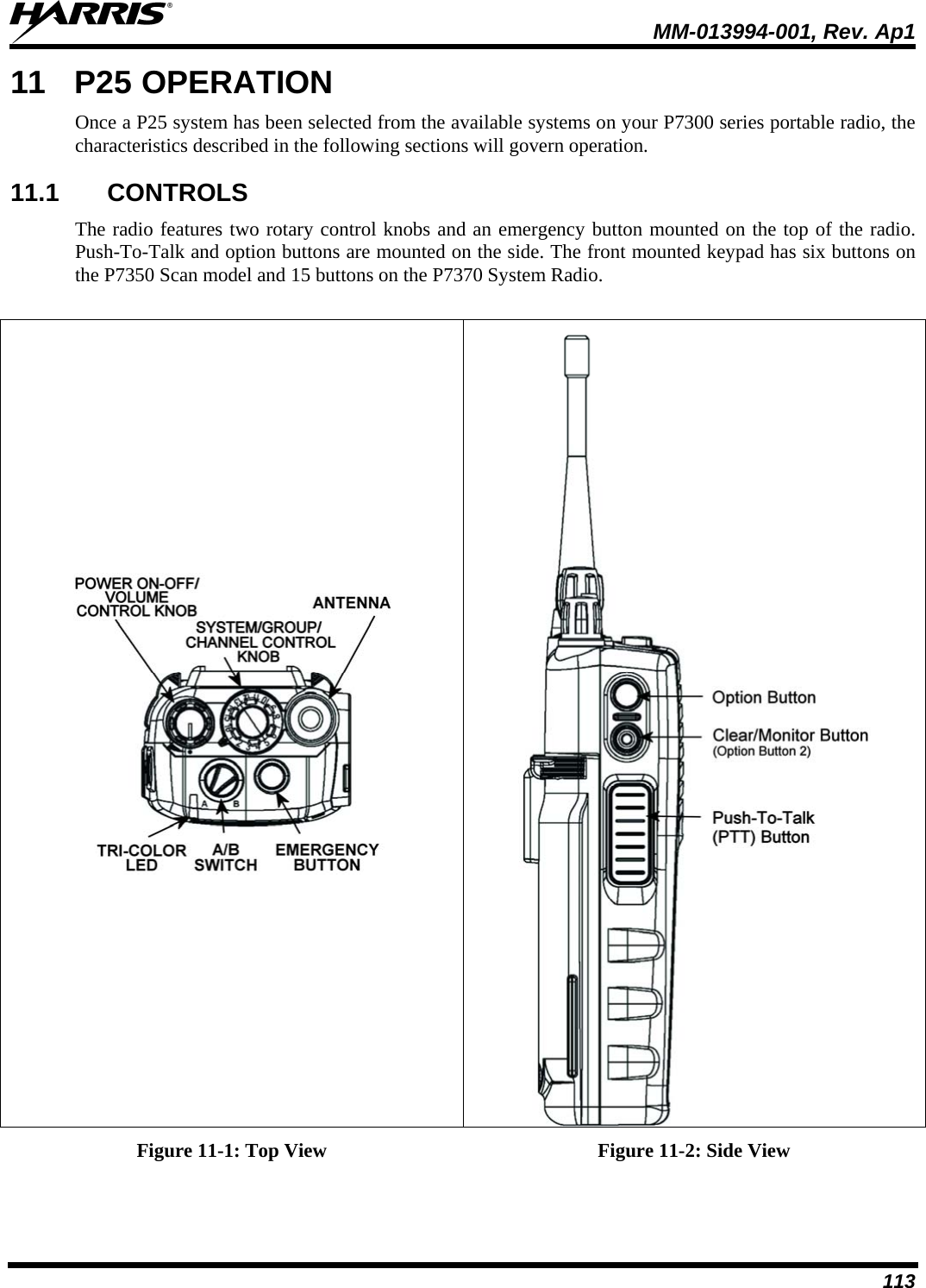
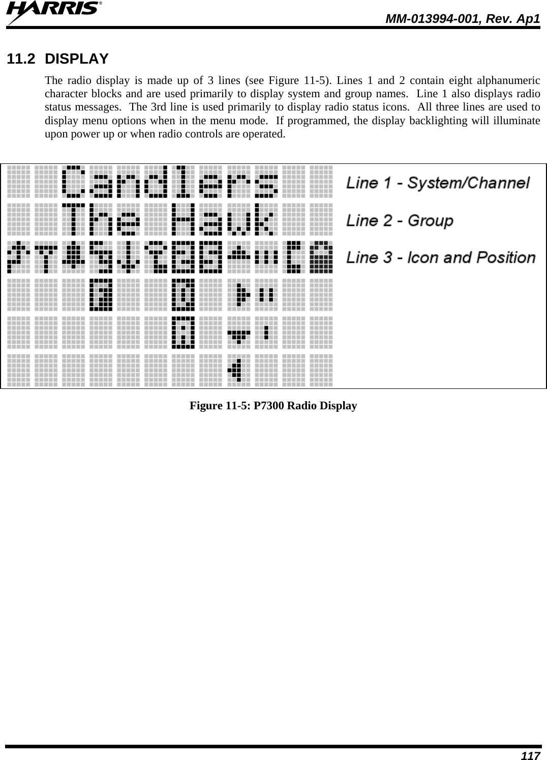
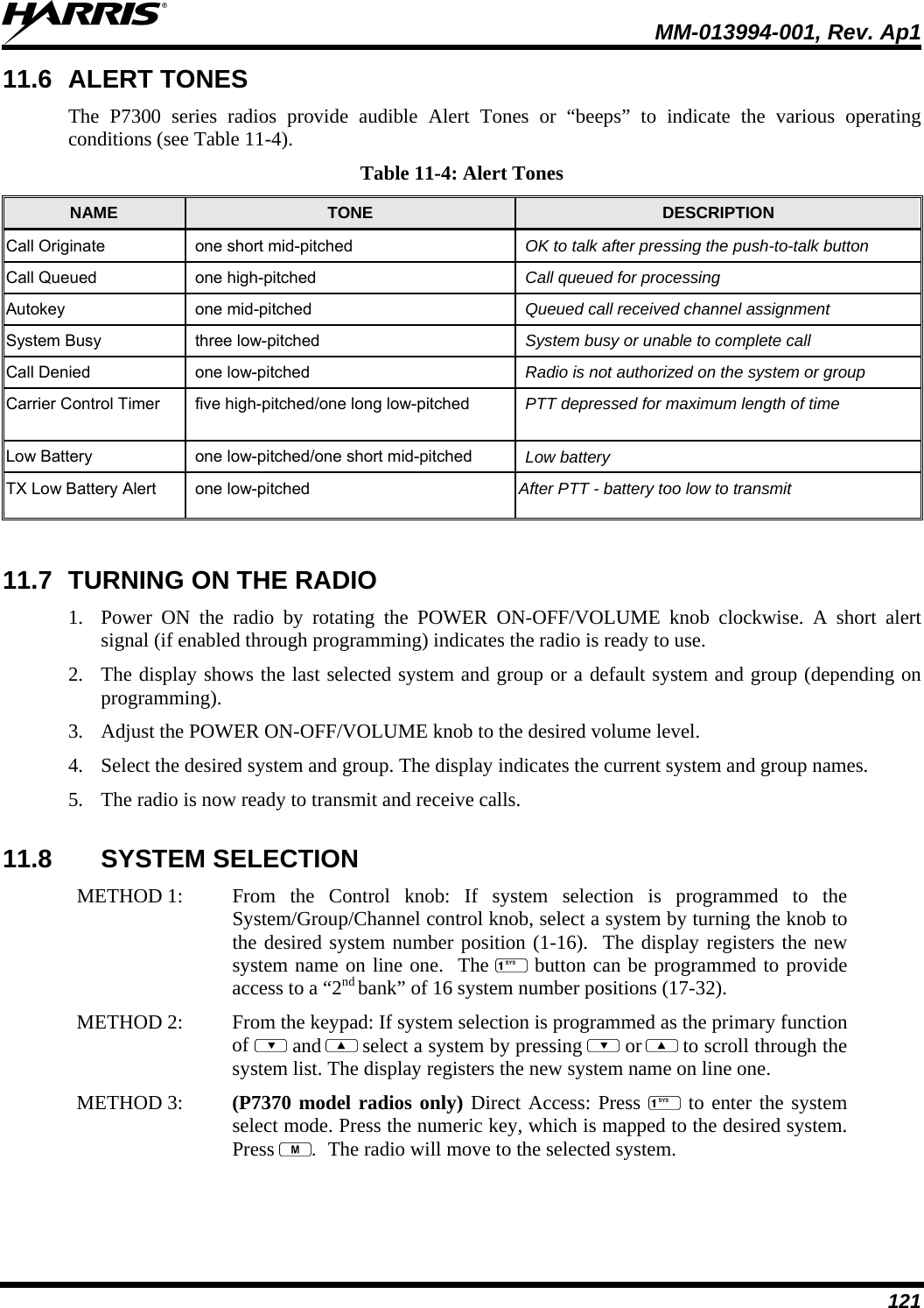
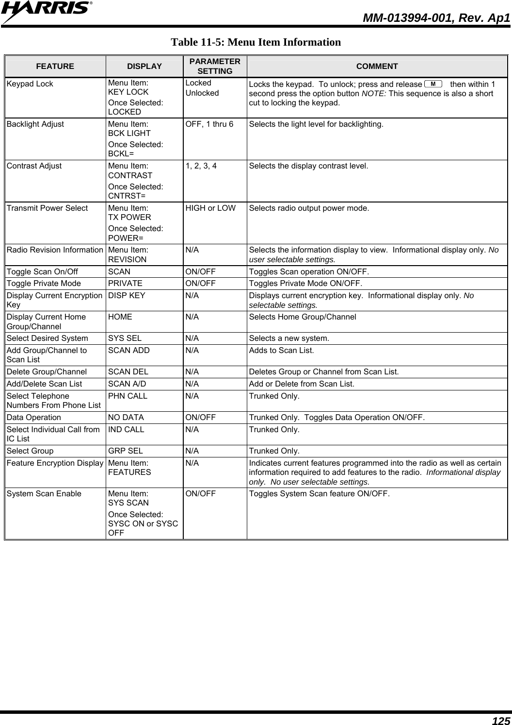
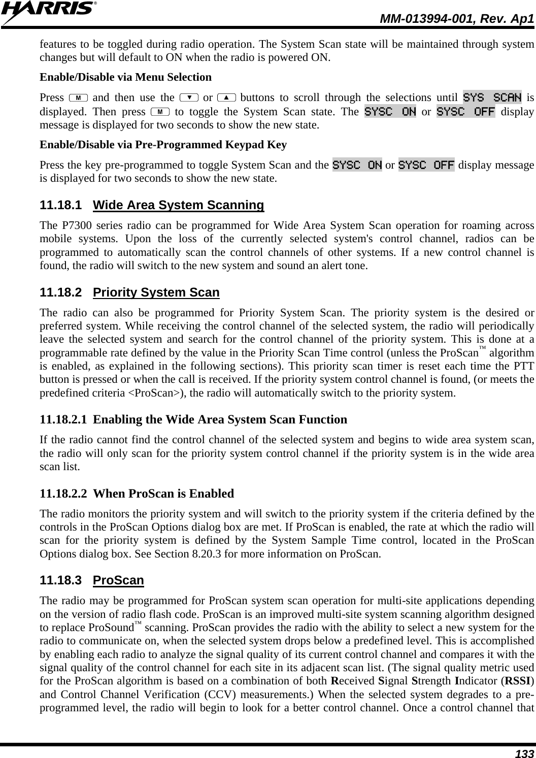
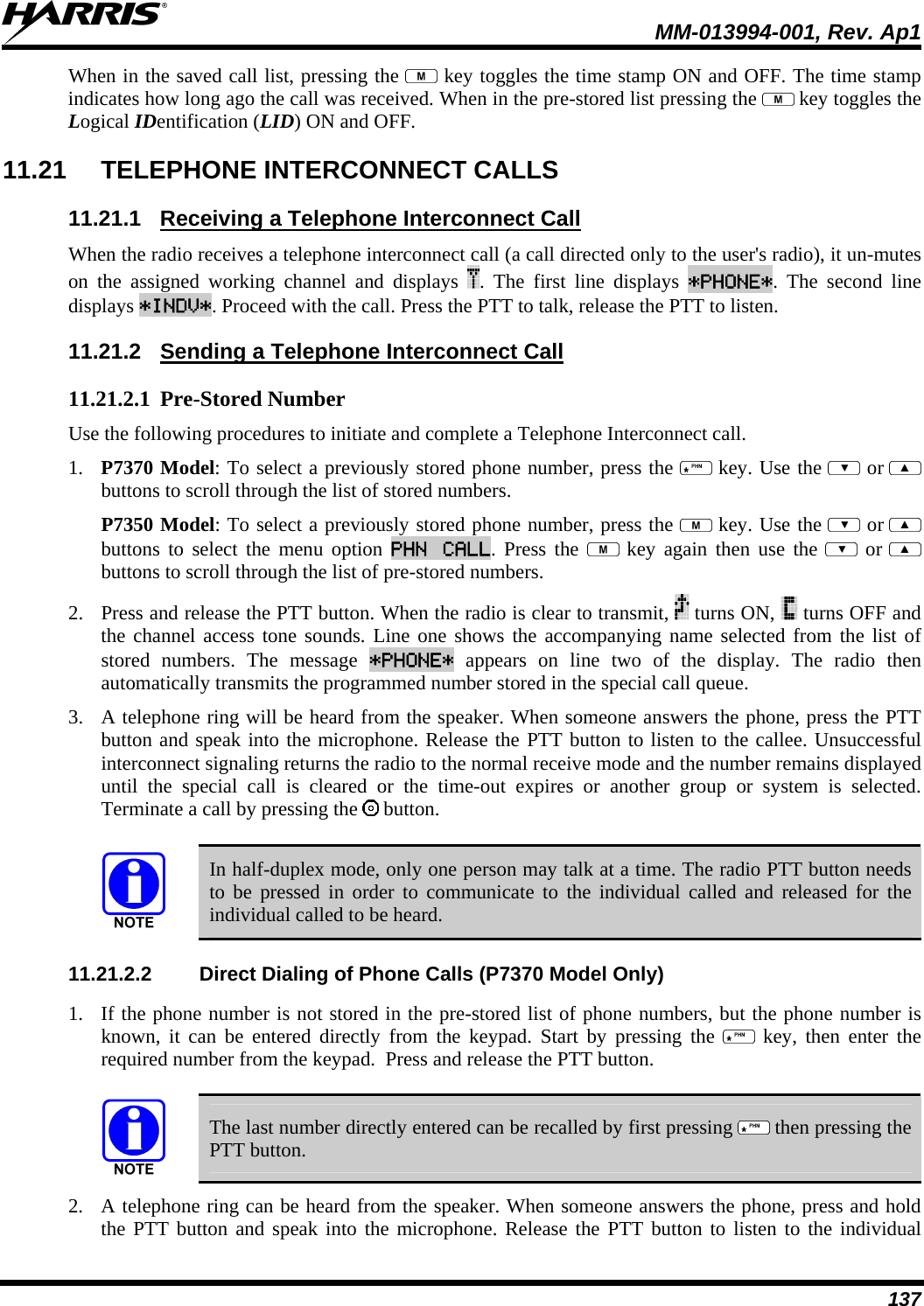
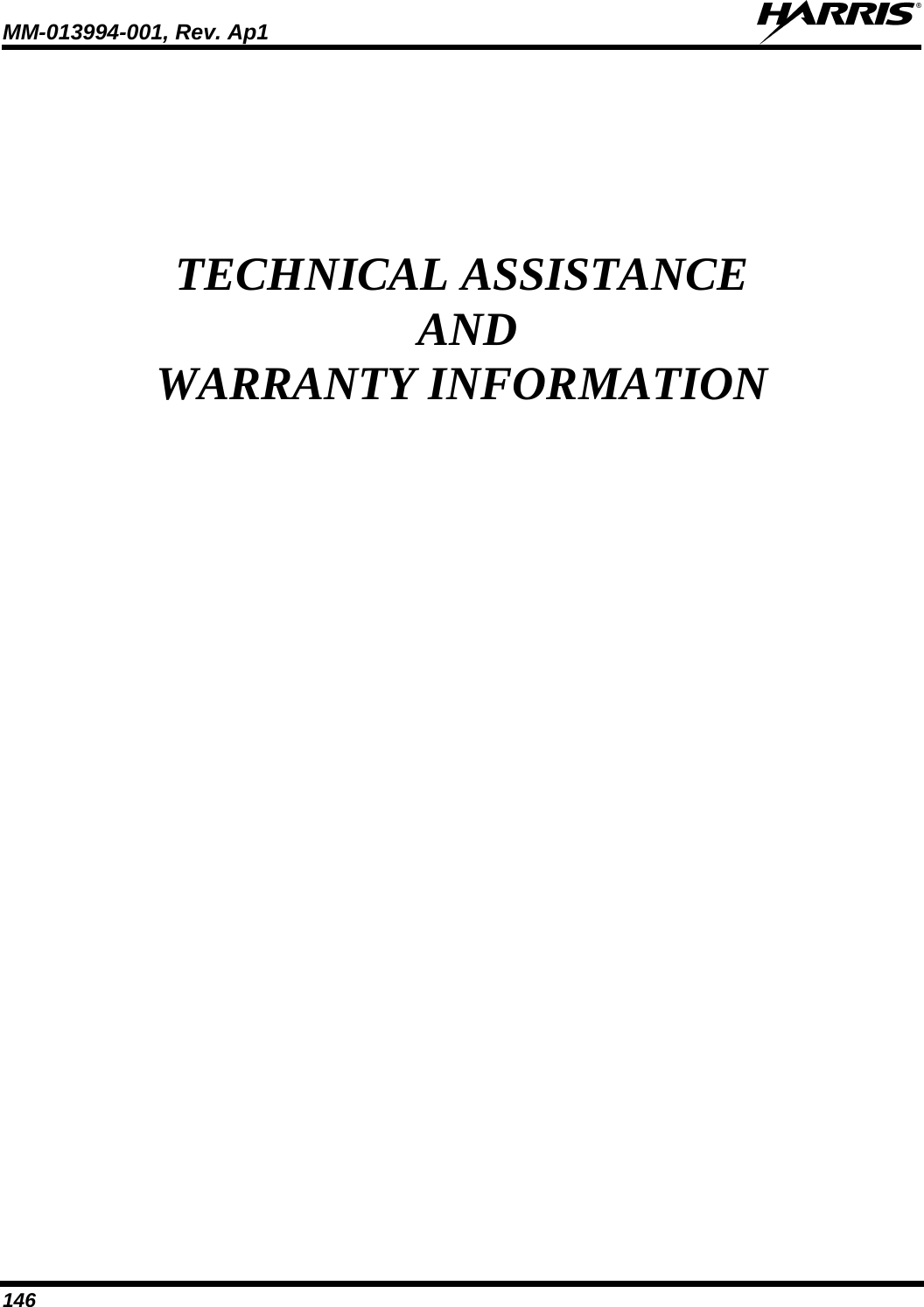
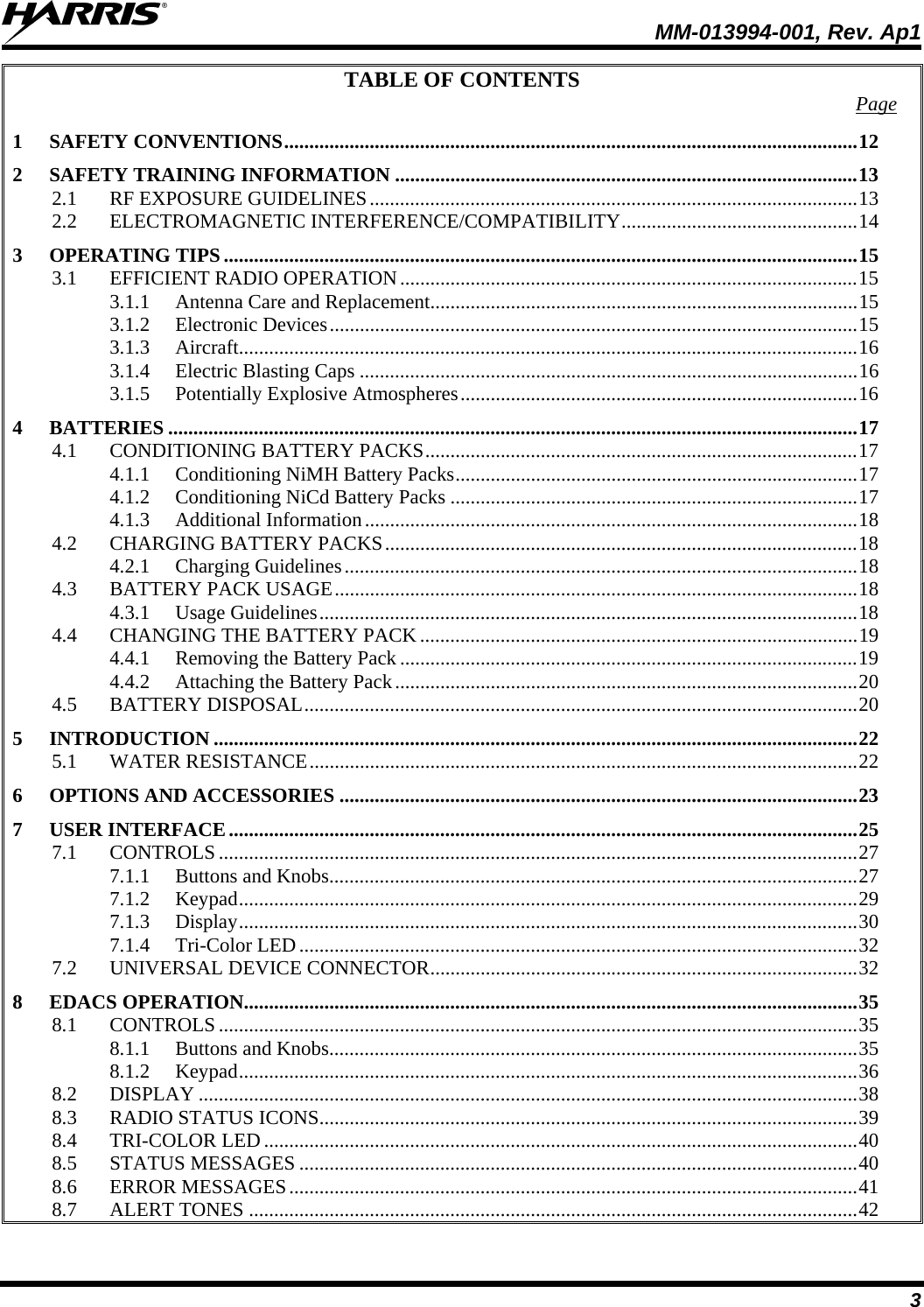
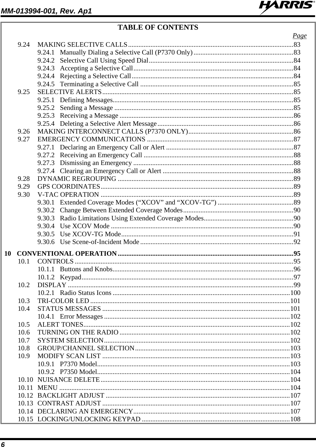
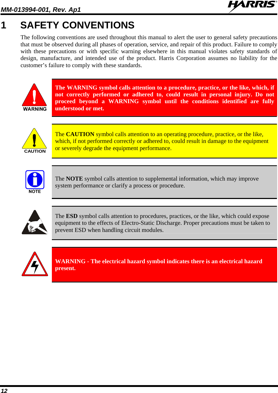
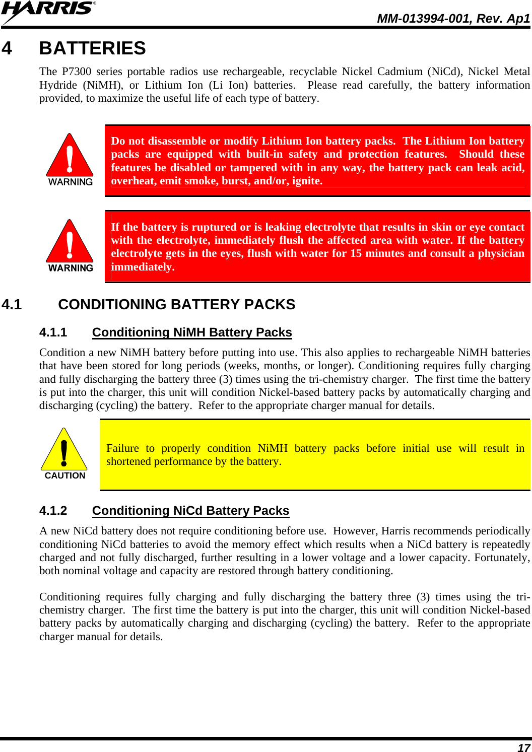
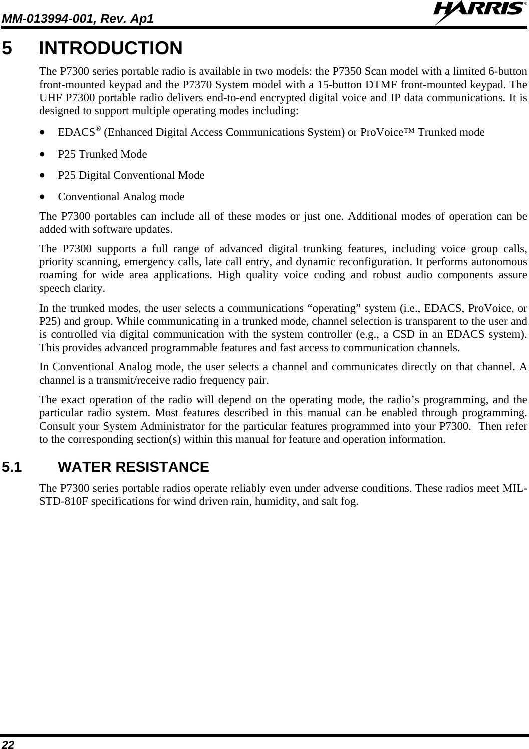
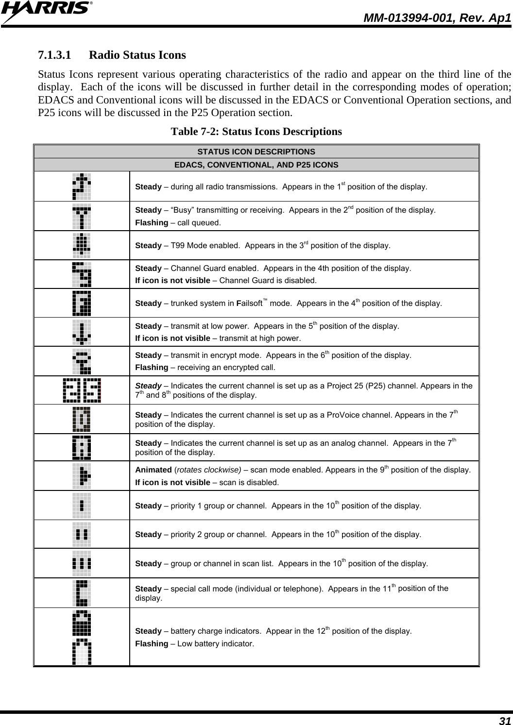
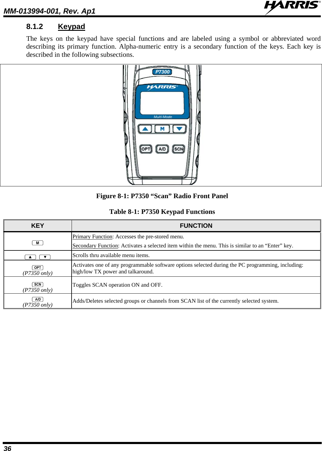
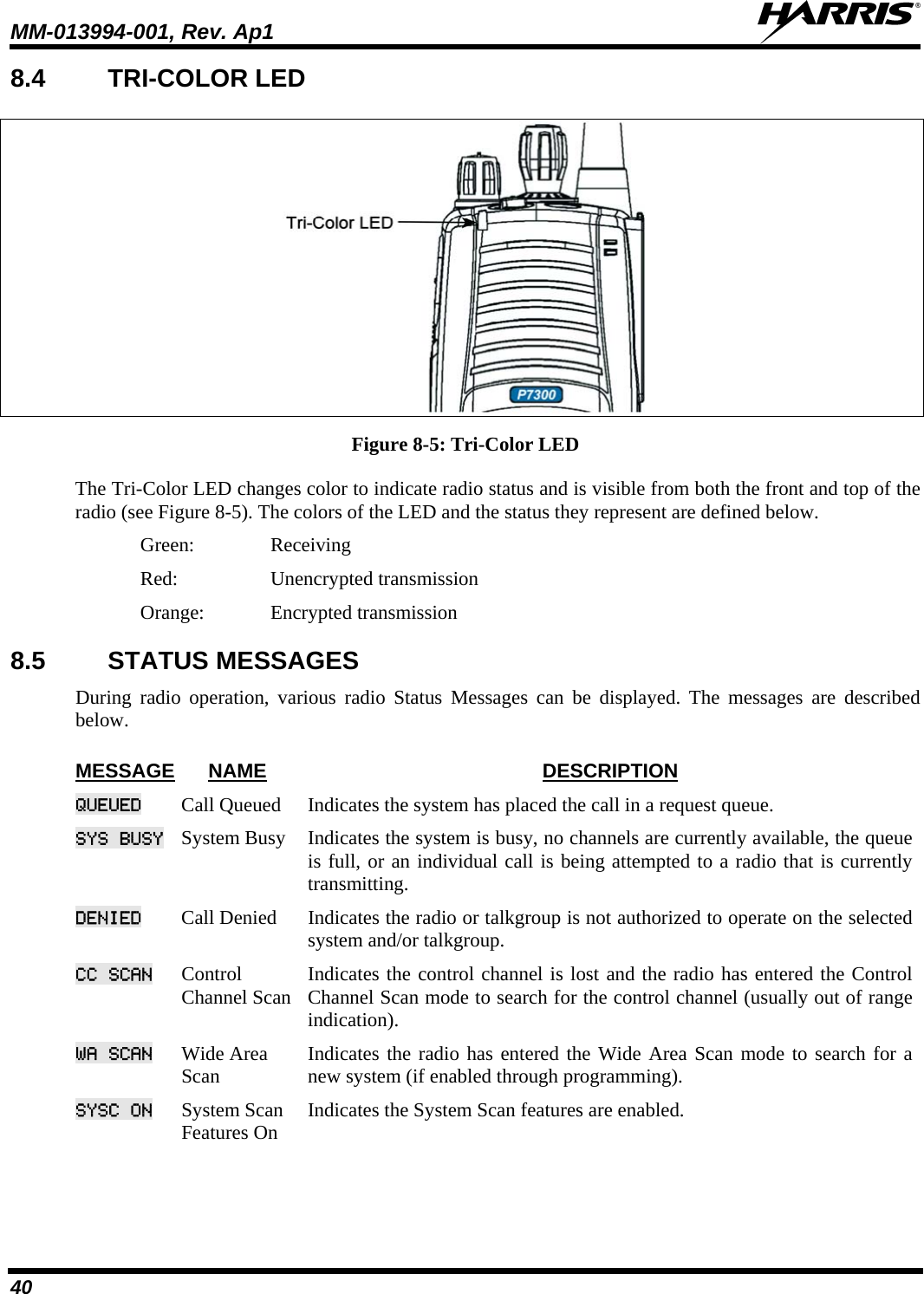
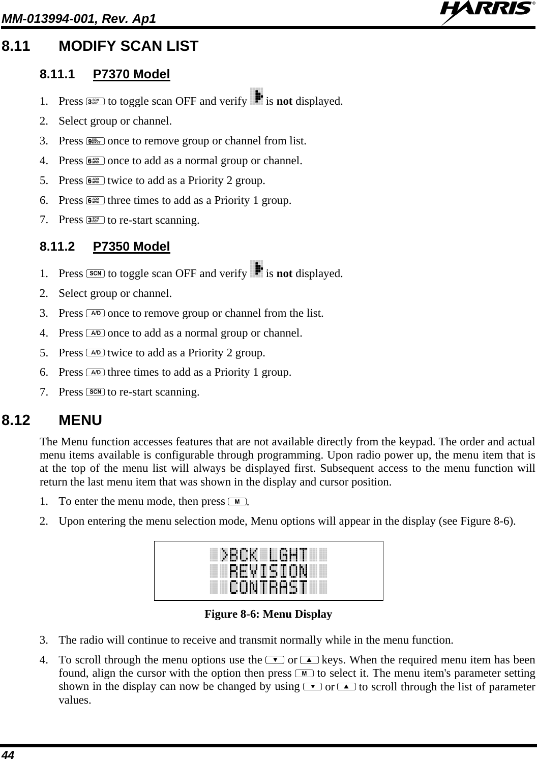
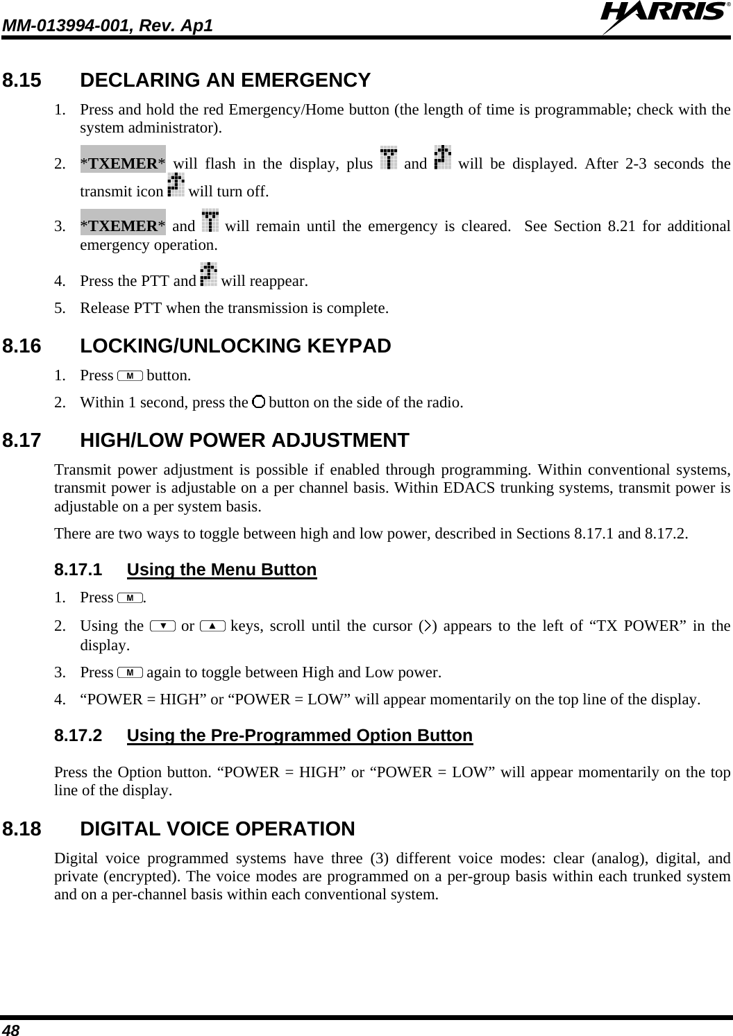
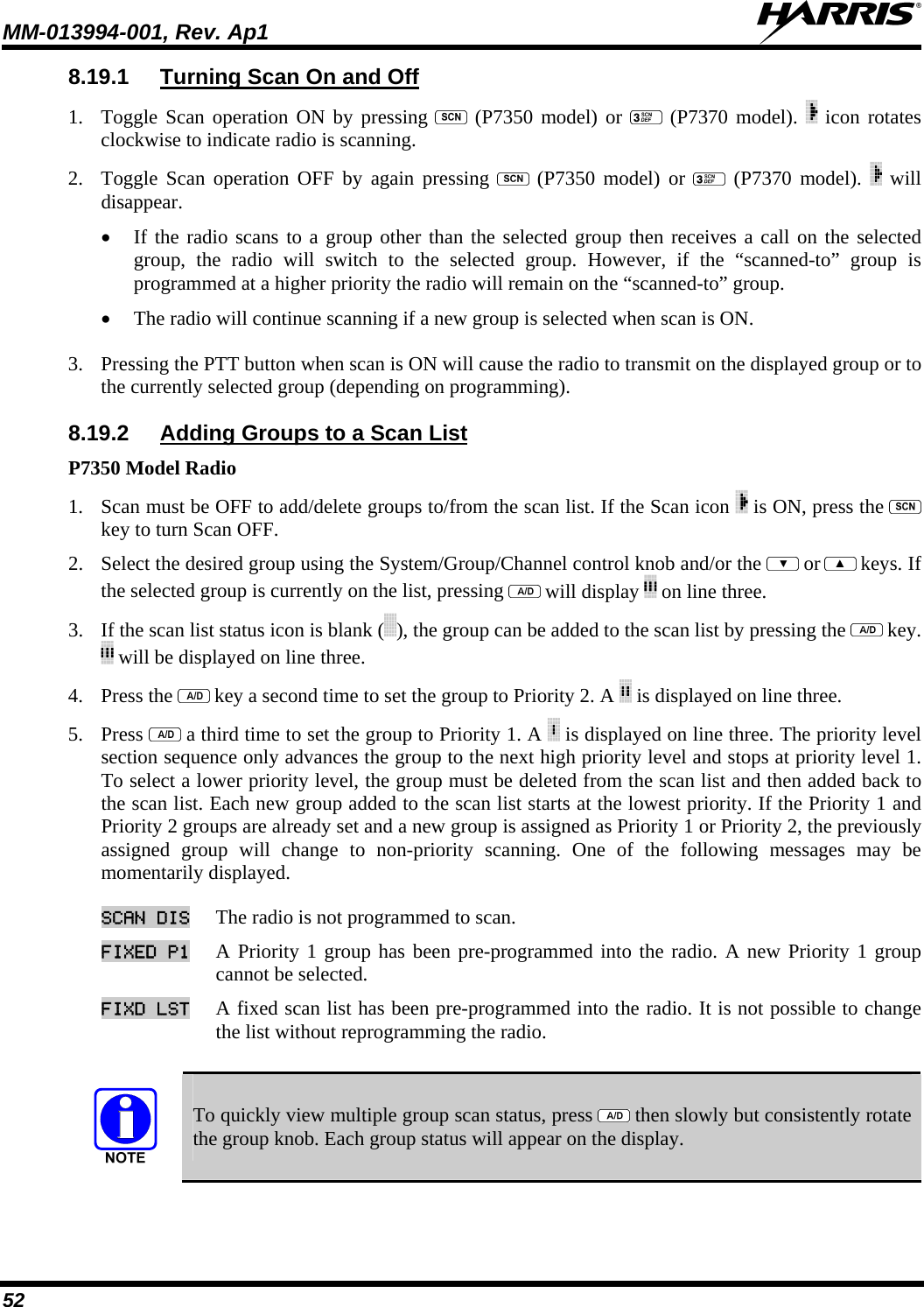
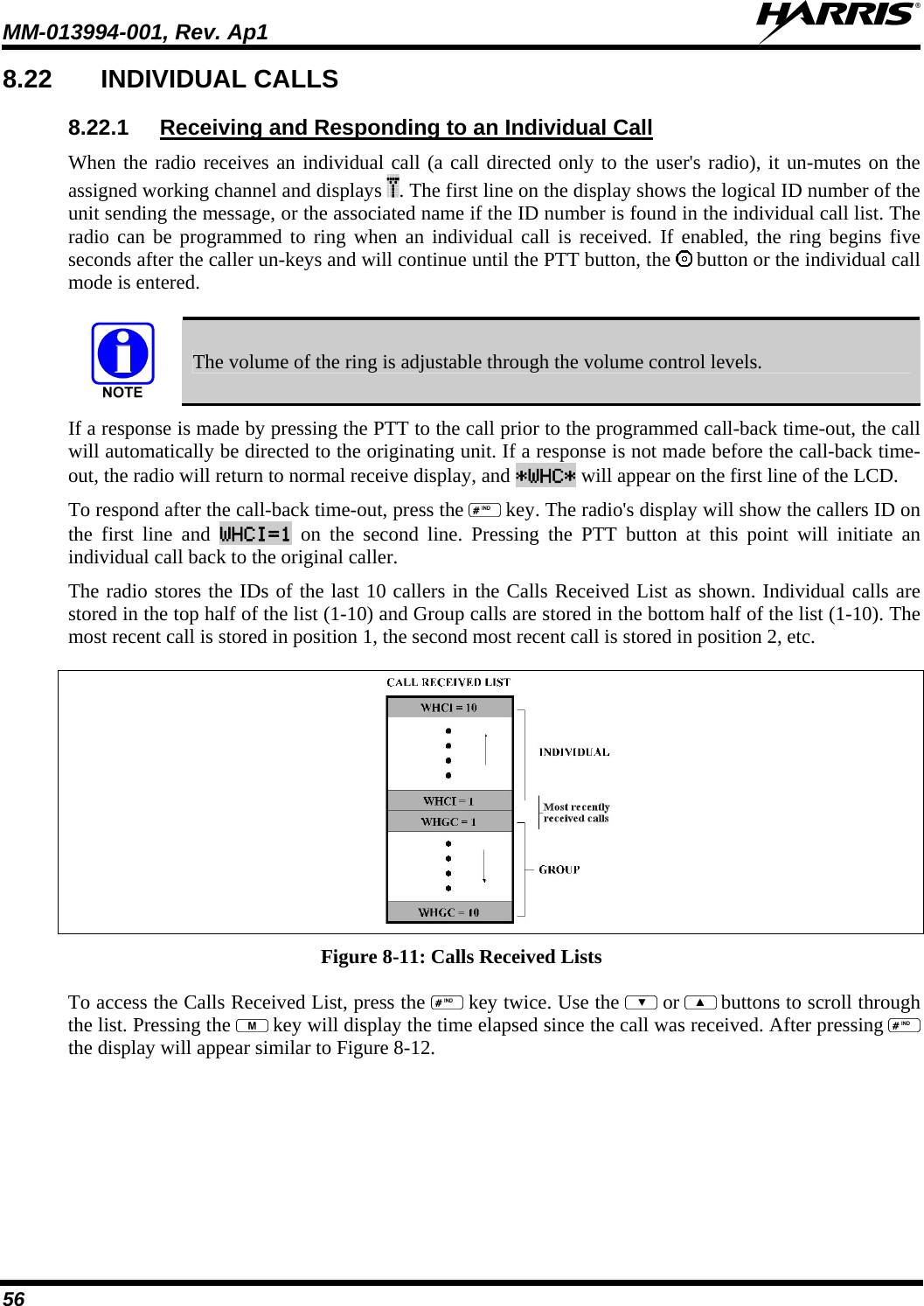
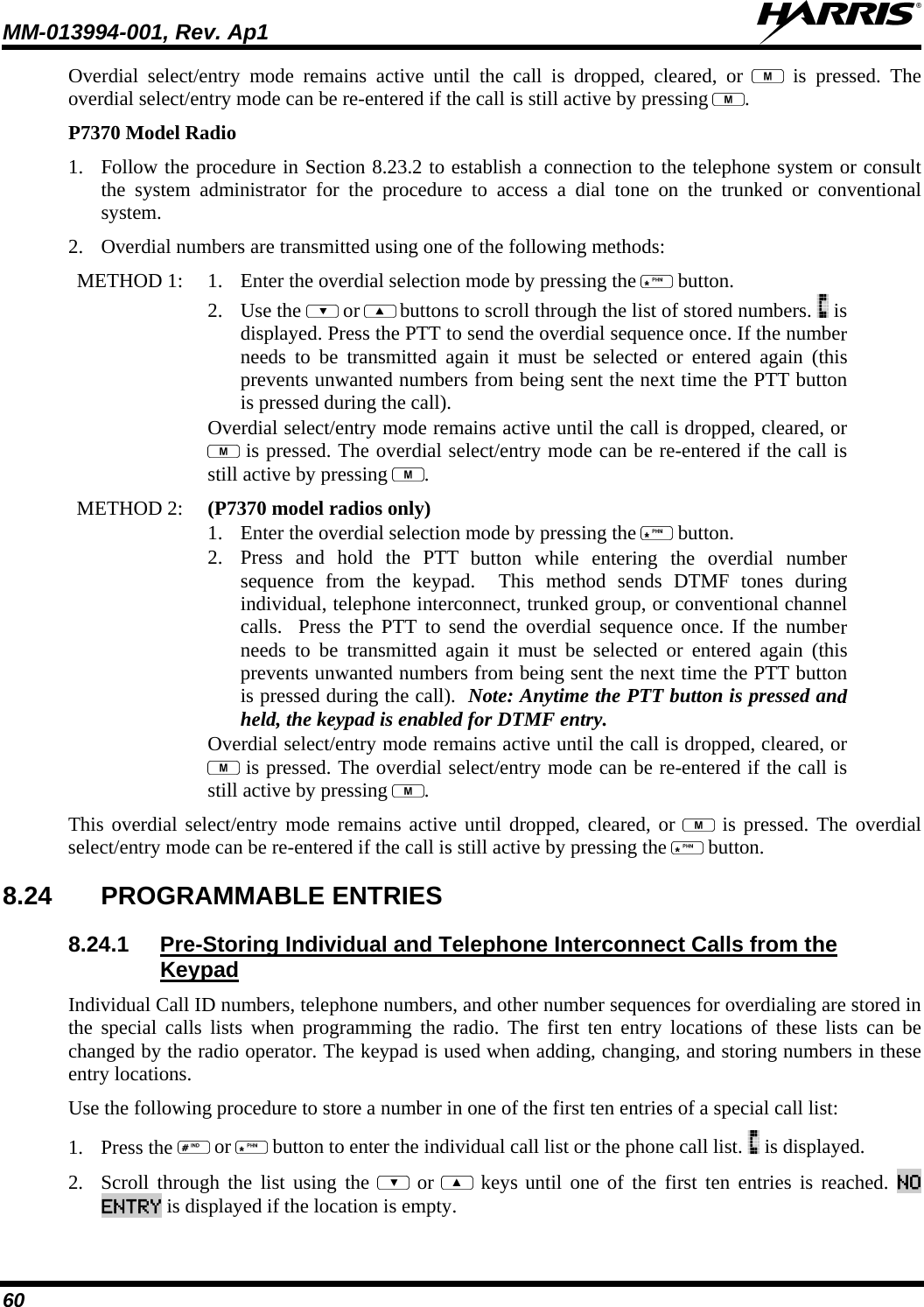
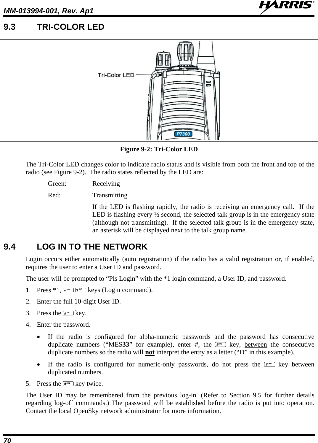
![MM-013994-001, Rev. Ap1 89 1. Press to declare an emergency. To clear an emergency, press and hold Option 2 button . While holding , press the emergency button. Release both buttons when the “emergency cleared” tone sounds. 2. The radio returns to your default selected talk group. The “EMERGENCY” display is removed from the main screen. If the radio is in stealth mode, clearing the emergency will cause the radio to exit stealth mode. 9.28 DYNAMIC REGROUPING Dynamic regrouping requires that the network administrator determine which radio users should be formed into an impromptu talk group to respond to particular emergency conditions. The administrator will edit the personalities of the affected radios to include an emergency profile and then page the affected radios to re-register with the network to receive their edited personalities. In response, affected radios automatically re-register to receive their edited personalities. During re-registration, subscriber equipment will default to the emergency profile selected by the administrator. 9.29 GPS COORDINATES The radio’s current latitude and longitude coordinates may be displayed using the “GPS” menu. The following procedure assumes a GPS antenna is connected to the radio and it is receiving adequate signals from GPS satellites. 1. Press or until the “GPS” menu appears in the display. Current GPS coordinate latitude and longitude data continuously scrolls in the top line of the display in a degrees:minutes:seconds format. 2. Press or to change to another menu. If the internal GPS receiver’s data is expired (30 minutes or more) or unavailable, the radio uses the serving base station’s coordinates [GPS (Site) is displayed]. The GPS Menu will also indicate if the data is aged (2 minutes or more) [GPS (Aged) is displayed]. 9.30 V-TAC OPERATION 9.30.1 Extended Coverage Modes (“XCOV” and “XCOV-TG”) In addition to all standard portable radio operating capabilities, Extended Coverage adds the V-TAC’s bridging (vehicular repeat) functionality for accessing the OpenSky radio network. Each portable radio connected to the V-TAC using Extended Coverage is considered a “client” on the V-TAC. Extended Coverage benefits portable radio users since it allows them to get network connectivity using the V-TAC’s higher transmit output power and better antenna system. The V-TAC supports two Extended Coverage modes: Extended Coverage for individual users (display reads “XCOV”) and Extended Coverage for a talk group (display reads “XCOV-TG”). Typically, Extended Coverage is used after the vehicle’s operator has exited the vehicle with a portable radio unit and the portable unit requires this bridging functionality to access the OpenSky radio network.](https://usermanual.wiki/HARRIS/TR-0054-E/User-Guide-1132261-Page-90.png)