HARRIS TR-0054-E Dual Band P7300 User Manual Manual
HARRIS CORPORATION Dual Band P7300 Manual
HARRIS >
Manual

Rhein Tech Laboratories, Inc. Client: Harris Corporation
360 Herndon Parkway Model: P7300 UHF Radio
Suite 1400 FCC ID: OWDTR-0054-E
Herndon, VA 20170 Standards: FCC Part 90
http://www.rheintech.com Report #: 2009141
60 of 75
Appendix M: Manual
Please refer to the following pages for the manual.
Operator’s Manual
MM-013994-001
Rev. Ap1, Jun/09
P7300 FAMILY
PORTABLE RADIOS
UHF, 700/800 MHz

MM-013994-001, Rev. Ap1
2
MANUAL REVISION HISTORY
REV DATE REASON FOR REVISION
- Jan/09 Initial release.
A Jun/09 Added SAR information and support for dual band P7300 portable radio.
Harris Technical Publications would particularly appreciate feedback on any errors found in this document and suggestions on how the
document could be improved. Submit your comments and suggestions to:
Harris Corporation
RF Communications Division Fax your comments to: 1-434-455-6851
Technical Publications or
221 Jefferson Ridge Parkway e-mail us at: techpubs@tycoelectronics.com
Lynchburg, VA 24501
ACKNOWLEDGEMENTS
The software contained in this device is copyrighted by Harris Corporation Unpublished rights are reserved under the copyright laws of the
United States.
This device is made under license under one or more of the following US patents: 4,590,473; 4,636,791; 5,148,482; 5,185,796; 5,271,017;
5,377,229; 4,716,407; 4,972,460; 5,502,767; 5,146,497; 5,164,986; 5,185,795; 5,226,084; 5,247,579; ; 5,491,772; 5,517,511; 5,630,011;
5,649,050; 5,701,390; 5,715,365; 5,754,974; 5,826,222; 5,870,405; 6,161,089; and 6,199,037 B1. DVSI claims certain rights, including
patent rights under aforementioned U.S. patents, and under other U.S. and foreign patents and patents pending. Any use of this software or
technology requires a separate written license from DVSI.
CREDITS!
EDACS is a registered trademark of Harris Corporation
AMBE is a registered trademark and IMBE, AMBE+, and AMBE+2 are trademarks of Digital Voice Systems, Inc.
TORX is a registered trademark of CAMCAR division of TEXTRON, Inc.
All other product and brand names are trademarks, registered trademarks, or service marks of their respective holders.
NOTICE!
Tyco Electronics (“TE”) has divested its Wireless systems business to Harris Corporation (“HARRIS”). As a result, all references herein to
TE or M/A-COM shall be to HARRIS. Neither TE nor M/A-COM is an agent or affiliate of Harris.
Information and descriptions contained herein are the property of Harris Corporation. Such information and descriptions may not be copied
or reproduced by any means, or disseminated or distributed without the express prior written permission of Harris Corporation, RF
Communications Division, 221 Jefferson Ridge Parkway, Lynchburg, VA 24501.
This manual covers Harris Corporation products manufactured and sold by Harris Corporation.
This product conforms to the European Union WEEE Directive 2002/96/EC. Do not dispose of this product in a public
landfill. Take it to a recycling center at the end of its life.
The voice coding technology embodied in this product is protected by intellectual property rights including patent rights, copyrights, and
trade secrets of Digital Voice Systems, Inc. The user of this technology is explicitly prohibited from attempting to decompile, reverse
engineer, or disassemble the Object Code, or in any other way convert the Object Code into human-readable form.
Repairs to this equipment should be made only by an authorized service technician or facility designated by the supplier. Any repairs,
alterations, or substitution of recommended parts made by the user to this equipment not approved by the manufacturer could void the
user’s authority to operate the equipment in addition to the manufacturer’s warranty.
This manual is published by Harris Corporation, without any warranty. Improvements and changes to this manual necessitated by typographical errors,
inaccuracies of current information, or improvements to programs and/or equipment, may be made by Harris Corporation, at any time and without notice.
Such changes will be incorporated into new editions of this manual. No part of this manual may be reproduced or transmitted in any form or by any means,
electronic or mechanical, including photocopying and recording, for any purpose, without the express written permission of Harris Corporation
Copyright© 2009 Harris Corporation. All rights reserved.

MM-013994-001, Rev. Ap1
3
TABLE OF CONTENTS Page
1 SAFETY CONVENTIONS..................................................................................................................12
2 SAFETY TRAINING INFORMATION ............................................................................................13
2.1 RF EXPOSURE GUIDELINES.................................................................................................13
2.2 ELECTROMAGNETIC INTERFERENCE/COMPATIBILITY...............................................14
3 OPERATING TIPS ..............................................................................................................................15
3.1 EFFICIENT RADIO OPERATION...........................................................................................15
3.1.1 Antenna Care and Replacement.....................................................................................15
3.1.2 Electronic Devices.........................................................................................................15
3.1.3 Aircraft...........................................................................................................................16
3.1.4 Electric Blasting Caps ...................................................................................................16
3.1.5 Potentially Explosive Atmospheres...............................................................................16
4 BATTERIES .........................................................................................................................................17
4.1 CONDITIONING BATTERY PACKS......................................................................................17
4.1.1 Conditioning NiMH Battery Packs................................................................................17
4.1.2 Conditioning NiCd Battery Packs .................................................................................17
4.1.3 Additional Information..................................................................................................18
4.2 CHARGING BATTERY PACKS..............................................................................................18
4.2.1 Charging Guidelines......................................................................................................18
4.3 BATTERY PACK USAGE........................................................................................................18
4.3.1 Usage Guidelines...........................................................................................................18
4.4 CHANGING THE BATTERY PACK .......................................................................................19
4.4.1 Removing the Battery Pack ...........................................................................................19
4.4.2 Attaching the Battery Pack............................................................................................20
4.5 BATTERY DISPOSAL..............................................................................................................20
5 INTRODUCTION ................................................................................................................................22
5.1 WATER RESISTANCE.............................................................................................................22
6 OPTIONS AND ACCESSORIES .......................................................................................................23
7 USER INTERFACE.............................................................................................................................25
7.1 CONTROLS...............................................................................................................................27
7.1.1 Buttons and Knobs.........................................................................................................27
7.1.2 Keypad...........................................................................................................................29
7.1.3 Display...........................................................................................................................30
7.1.4 Tri-Color LED...............................................................................................................32
7.2 UNIVERSAL DEVICE CONNECTOR.....................................................................................32
8 EDACS OPERATION..........................................................................................................................35
8.1 CONTROLS...............................................................................................................................35
8.1.1 Buttons and Knobs.........................................................................................................35
8.1.2 Keypad...........................................................................................................................36
8.2 DISPLAY ...................................................................................................................................38
8.3 RADIO STATUS ICONS...........................................................................................................39
8.4 TRI-COLOR LED......................................................................................................................40
8.5 STATUS MESSAGES ...............................................................................................................40
8.6 ERROR MESSAGES.................................................................................................................41
8.7 ALERT TONES .........................................................................................................................42

MM-013994-001, Rev. Ap1
4
TABLE OF CONTENTS Page
8.8 TURNING ON THE RADIO .....................................................................................................42
8.9 SYSTEM SELECTION..............................................................................................................43
8.10 GROUP/CHANNEL SELECTION............................................................................................43
8.11 MODIFY SCAN LIST ...............................................................................................................44
8.11.1 P7370 Model..................................................................................................................44
8.11.2 P7350 Model..................................................................................................................44
8.12 MENU ........................................................................................................................................44
8.12.1 Menu Item Selection Process.........................................................................................45
8.13 BACKLIGHT ADJUST .............................................................................................................47
8.14 CONTRAST ADJUST ...............................................................................................................47
8.15 DECLARING AN EMERGENCY.............................................................................................48
8.16 LOCKING/UNLOCKING KEYPAD ........................................................................................48
8.17 HIGH/LOW POWER ADJUSTMENT......................................................................................48
8.17.1 Using the Menu Button..................................................................................................48
8.17.2 Using the Pre-Programmed Option Button....................................................................48
8.18 DIGITAL VOICE OPERATION ...............................................................................................48
8.18.1 Clear Mode ....................................................................................................................49
8.18.2 Digital Mode..................................................................................................................49
8.18.3 Private Mode..................................................................................................................49
8.18.4 Private Operation...........................................................................................................50
8.19 SCANNING TRUNKED GROUPS...........................................................................................51
8.19.1 Turning Scan On and Off ..............................................................................................52
8.19.2 Adding Groups to a Scan List........................................................................................52
8.19.3 Deleting Groups from a Scan List .................................................................................53
8.19.4 Nuisance Delete.............................................................................................................54
8.20 SCANNING TRUNKED SYSTEMS.........................................................................................54
8.20.1 Wide Area System Scanning .........................................................................................54
8.20.2 Priority System Scan......................................................................................................54
8.20.3 ProScan..........................................................................................................................55
8.21 EMERGENCY OPERATION....................................................................................................55
8.21.1 Receiving an Emergency Call .......................................................................................55
8.21.2 Declaring an Emergency Call........................................................................................55
8.22 INDIVIDUAL CALLS...............................................................................................................56
8.22.1 Receiving and Responding to an Individual Call ..........................................................56
8.22.2 Sending an Individual Call ............................................................................................57
8.22.3 Call Storage Lists...........................................................................................................57
8.23 TELEPHONE INTERCONNECT CALLS................................................................................58
8.23.1 Receiving a Telephone Interconnect Call......................................................................58
8.23.2 Sending a Telephone Interconnect Call.........................................................................58
8.23.3 Dual-Tone Multi-Frequency: Overdial/Conventional Mode.........................................59
8.24 PROGRAMMABLE ENTRIES .................................................................................................60
8.24.1 Pre-Storing Individual and Telephone Interconnect Calls from the Keypad.................60
8.25 STATUS/MESSAGE OPERATION..........................................................................................61
8.25.1 Status Operation ............................................................................................................61
8.25.2 Message Operation ........................................................................................................62
8.26 DYNAMIC REGROUP OPERATION......................................................................................62
8.26.1 Emergency Operation....................................................................................................62
8.27 MACRO KEY OPERATION.....................................................................................................62

MM-013994-001, Rev. Ap1
5
TABLE OF CONTENTS Page
8.28 PORTABLE DATA....................................................................................................................62
8.28.1 Displays .........................................................................................................................63
8.28.2 DATA OFF Operation...................................................................................................63
8.28.3 DATA ON Operation ....................................................................................................63
8.28.4 Exiting Data Calls..........................................................................................................63
8.28.5 Scan Lockout Mode.......................................................................................................63
8.28.6 Data Lockout Mode.......................................................................................................64
9 OPENSKY OPERATION....................................................................................................................67
9.1 CONTROLS...............................................................................................................................67
9.1.1 Buttons and Knobs.........................................................................................................67
9.1.2 Keypad...........................................................................................................................68
9.2 RADIO STATUS ICONS...........................................................................................................69
9.3 TRI-COLOR LED......................................................................................................................70
9.4 LOG IN TO THE NETWORK...................................................................................................70
9.5 LOG OFF THE NETWORK......................................................................................................71
9.6 PERSONALITY.........................................................................................................................71
9.6.1 Profiles...........................................................................................................................71
9.6.2 Talk Groups...................................................................................................................72
9.7 OPENSKY DISPLAY OVERVIEW..........................................................................................72
9.7.1 Display’s Top Line........................................................................................................72
9.7.2 Display’s Second Line...................................................................................................72
9.7.3 Dwell Display................................................................................................................72
9.8 ALERT TONES .........................................................................................................................73
9.9 BASIC MENU STRUCTURE ...................................................................................................74
9.10 KEYPAD FUNCTION COMMANDS (P7370 ONLY).............................................................76
9.11 QUICK KEYS (P7370 ONLY) ..................................................................................................77
9.12 LOCK/UNLOCK THE KEYPAD..............................................................................................77
9.13 DUAL-TONE MULTI-FREQUENCY (P7370 ONLY) ............................................................77
9.14 CHANGING THE ACTIVE PROFILE .....................................................................................78
9.15 CHANGING THE SELECTED TALK GROUP.......................................................................78
9.16 ADJUSTING DISPLAY AND BUTTON BACKLIGHT BRIGHTNESS................................78
9.17 STEALTH MODE......................................................................................................................78
9.17.1 Enabling Stealth Mode ..................................................................................................78
9.17.2 Disabling Stealth Mode .................................................................................................78
9.17.3 Stealth Mode using A/B Switch ....................................................................................79
9.18 ADJUSTING SIDE TONE AUDIO LEVEL .............................................................................79
9.19 CHANGE OPERATING MODE ...............................................................................................79
9.20 RECEIVING AND TRANSMITTING VOICE CALLS ...........................................................79
9.20.1 Receiving a Voice Call..................................................................................................79
9.20.2 Transmitting a Voice Call..............................................................................................79
9.21 ADJUSTING AUDIO TREBLE LEVEL...................................................................................80
9.22 TALK GROUP LOCK OUT......................................................................................................80
9.22.1 Lock Out a Talk Group..................................................................................................81
9.22.2 Unlock a Talk Group.....................................................................................................81
9.23 SCANNING................................................................................................................................81
9.23.1 Selecting Scan Modes....................................................................................................81
9.23.2 Checking or Changing Active Scan Mode ....................................................................82
9.23.3 Scanning Priority...........................................................................................................82

MM-013994-001, Rev. Ap1
6
TABLE OF CONTENTS Page
9.24 MAKING SELECTIVE CALLS................................................................................................83
9.24.1 Manually Dialing a Selective Call (P7370 Only)..........................................................83
9.24.2 Selective Call Using Speed Dial....................................................................................84
9.24.3 Accepting a Selective Call.............................................................................................84
9.24.4 Rejecting a Selective Call..............................................................................................84
9.24.5 Terminating a Selective Call .........................................................................................85
9.25 SELECTIVE ALERTS...............................................................................................................85
9.25.1 Defining Messages.........................................................................................................85
9.25.2 Sending a Message ........................................................................................................85
9.25.3 Receiving a Message .....................................................................................................86
9.25.4 Deleting a Selective Alert Message...............................................................................86
9.26 MAKING INTERCONNECT CALLS (P7370 ONLY).............................................................86
9.27 EMERGENCY COMMUNICATIONS .....................................................................................87
9.27.1 Declaring an Emergency Call or Alert ..........................................................................87
9.27.2 Receiving an Emergency Call .......................................................................................88
9.27.3 Dismissing an Emergency .............................................................................................88
9.27.4 Clearing an Emergency Call or Alert ............................................................................88
9.28 DYNAMIC REGROUPING ......................................................................................................89
9.29 GPS COORDINATES................................................................................................................89
9.30 V-TAC OPERATION ................................................................................................................89
9.30.1 Extended Coverage Modes (“XCOV” and “XCOV-TG”) ............................................89
9.30.2 Change Between Extended Coverage Modes................................................................90
9.30.3 Radio Limitations Using Extended Coverage Modes....................................................90
9.30.4 Use XCOV Mode ..........................................................................................................90
9.30.5 Use XCOV-TG Mode....................................................................................................91
9.30.6 Use Scene-of-Incident Mode.........................................................................................92
10 CONVENTIONAL OPERATION......................................................................................................95
10.1 CONTROLS ...............................................................................................................................95
10.1.1 Buttons and Knobs.........................................................................................................96
10.1.2 Keypad...........................................................................................................................97
10.2 DISPLAY ...................................................................................................................................99
10.2.1 Radio Status Icons .......................................................................................................100
10.3 TRI-COLOR LED ....................................................................................................................101
10.4 STATUS MESSAGES .............................................................................................................101
10.4.1 Error Messages ............................................................................................................102
10.5 ALERT TONES........................................................................................................................102
10.6 TURNING ON THE RADIO ...................................................................................................102
10.7 SYSTEM SELECTION............................................................................................................102
10.8 GROUP/CHANNEL SELECTION..........................................................................................103
10.9 MODIFY SCAN LIST .............................................................................................................103
10.9.1 P7370 Model................................................................................................................103
10.9.2 P7350 Model................................................................................................................104
10.10 NUISANCE DELETE..............................................................................................................104
10.11 MENU ......................................................................................................................................104
10.12 BACKLIGHT ADJUST ...........................................................................................................107
10.13 CONTRAST ADJUST .............................................................................................................107
10.14 DECLARING AN EMERGENCY...........................................................................................107
10.15 LOCKING/UNLOCKING KEYPAD ......................................................................................108

MM-013994-001, Rev. Ap1
7
TABLE OF CONTENTS Page
10.16 HIGH/LOW POWER ADJUSTMENT....................................................................................108
10.17 DIGITAL VOICE OPERATION .............................................................................................108
10.17.1 Clear Mode ..................................................................................................................108
10.17.2 Digital Mode................................................................................................................109
10.18 RECEIVING A CALL .............................................................................................................109
10.19 SENDING A CALL .................................................................................................................110
11 P25 OPERATION...............................................................................................................................113
11.1 CONTROLS.............................................................................................................................113
11.1.1 Buttons and Knobs.......................................................................................................114
11.1.2 Keypad.........................................................................................................................115
11.2 DISPLAY .................................................................................................................................117
11.3 RADIO STATUS ICONS.........................................................................................................118
11.4 TRI-COLOR LED....................................................................................................................119
11.5 STATUS MESSAGES .............................................................................................................119
11.5.1 Error Messages ............................................................................................................120
11.6 ALERT TONES .......................................................................................................................121
11.7 TURNING ON THE RADIO...................................................................................................121
11.8 SYSTEM SELECTION............................................................................................................121
11.8.1 GROUP/CHANNEL SELECTION.............................................................................122
11.9 MODIFY SCAN LIST .............................................................................................................122
11.9.1 P7370 Model................................................................................................................122
11.9.2 P7350 Model................................................................................................................123
11.10 MENU ......................................................................................................................................123
11.10.1 Menu Item Selection Process.......................................................................................123
11.11 BACKLIGHT ADJUST ...........................................................................................................126
11.12 CONTRAST ADJUST .............................................................................................................126
11.13 DECLARING AN EMERGENCY...........................................................................................126
11.14 LOCKING/UNLOCKING KEYPAD ......................................................................................127
11.15 HIGH/LOW POWER ADJUSTMENT....................................................................................127
11.15.1 Using the Menu Button................................................................................................127
11.15.2 Using the Pre-Programmed Option Button..................................................................127
11.16 DIGITAL VOICE OPERATION .............................................................................................127
11.16.1 Clear Mode ..................................................................................................................127
11.16.2 Digital Mode................................................................................................................128
11.16.3 Private Mode................................................................................................................128
11.16.4 Private Operation.........................................................................................................129
11.17 SCANNING TRUNKED GROUPS.........................................................................................130
11.17.1 Turning Scan On and Off ............................................................................................130
11.17.2 Adding Groups to a Scan List......................................................................................131
11.17.3 Deleting Groups from a Scan List ...............................................................................132
11.17.4 Nuisance Delete...........................................................................................................132
11.18 SCANNING TRUNKED SYSTEMS.......................................................................................132
11.18.1 Wide Area System Scanning .......................................................................................133
11.18.2 Priority System Scan ...................................................................................................133
11.18.3 ProScan........................................................................................................................133
11.19 EMERGENCY OPERATION..................................................................................................134
11.19.1 Receiving an Emergency Call .....................................................................................134
11.19.2 Declaring an Emergency Call......................................................................................134

MM-013994-001, Rev. Ap1
8
TABLE OF CONTENTS Page
11.20 INDIVIDUAL CALLS.............................................................................................................134
11.20.1 Receiving and Responding to an Individual Call ........................................................134
11.20.2 Sending an Individual Call ..........................................................................................135
11.20.3 Call Storage Lists.........................................................................................................136
11.21 TELEPHONE INTERCONNECT CALLS..............................................................................137
11.21.1 Receiving a Telephone Interconnect Call....................................................................137
11.21.2 Sending a Telephone Interconnect Call.......................................................................137
11.21.3 Dual-Tone Multi-Frequency: Overdial/Conventional Mode.......................................138
11.22 PROGRAMMABLE ENTRIES...............................................................................................139
11.22.1 Pre-Storing Individual and Telephone Interconnect Calls from the Keypad...............139
11.23 STATUS/MESSAGE OPERATION........................................................................................139
11.23.1 Status Operation ..........................................................................................................140
11.23.2 Message Operation ......................................................................................................140
11.24 MACRO KEY OPERATION...................................................................................................140
11.25 PORTABLE DATA..................................................................................................................141
11.25.1 Displays .......................................................................................................................141
11.25.2 DATA OFF Operation.................................................................................................141
11.25.3 DATA ON Operation ..................................................................................................141
11.25.4 Exiting Data Calls........................................................................................................142
11.25.5 Scan Lockout Mode.....................................................................................................142
11.25.6 Data Lockout Mode.....................................................................................................142
11.26 GROUP CALLS IN P25 MODE..............................................................................................142
11.26.1 Transmitting a Group Call...........................................................................................142
11.26.2 Receiving a Group Call ...............................................................................................143
11.27 INDIVIDUAL CALLS IN P25 MODE....................................................................................143
11.27.1 Transmitting an Individual Call...................................................................................143
11.27.2 Receiving an Individual Call .......................................................................................143
11.28 EMERGENCY GROUP CALLS IN P25 MODE....................................................................143
11.28.1 Declaring an Emergency Group Call...........................................................................143
11.28.2 Receiving an Emergency Group Call ..........................................................................144
12 IMMERSIBLE P7300 PREVENTIVE MAINTENANCE..............................................................147
12.1 TECHNICAL ASSISTANCE – IMMERSIBLE P7300...........................................................147
13 TECHNICAL ASSISTANCE............................................................................................................149
14 BASIC TROUBLESHOOTING........................................................................................................150
FIGURES
Figure 4-1: Removing the Battery Pack.........................................................................................................19
Figure 4-2: Attaching the Battery Pack..........................................................................................................20
Figure 7-1: P7300 Portable Radio..................................................................................................................26
Figure 7-2: Top View.....................................................................................................................................27
Figure 7-3: Side View....................................................................................................................................27
Figure 7-4: P7350 “Scan” Model Front Panel ...............................................................................................29
Figure 7-5: P7370 “System” Model Front Panel ...........................................................................................29
Figure 7-6: P7300 Radio Display...................................................................................................................30
Figure 7-7: Full Cycle Battery Charge Indicator ...........................................................................................32
Figure 7-8: Tri-Color LED.............................................................................................................................32
Figure 7-9: P7300 15-Pin Universal Device Connector.................................................................................33

MM-013994-001, Rev. Ap1
9
TABLE OF CONTENTS Page
Figure 8-1: P7350 “Scan” Radio Front Panel................................................................................................36
Figure 8-2: P7370 “System” Radio Front Panel ............................................................................................37
Figure 8-3: P7300 Radio Display...................................................................................................................38
Figure 8-4: Full Cycle Battery Charge Indicator ...........................................................................................39
Figure 8-5: Tri-Color LED.............................................................................................................................40
Figure 8-6: Menu Display..............................................................................................................................44
Figure 8-7: Backlight Menu Item Selection Parameter..................................................................................45
Figure 8-8: Backlight Menu Display .............................................................................................................45
Figure 8-9: System Encryption Key Display .................................................................................................50
Figure 8-10: Group/Channel Encryption Key Display ..................................................................................50
Figure 8-11: Calls Received Lists..................................................................................................................56
Figure 8-12: WHC Individual Call Display...................................................................................................57
Figure 8-13: Calls Received and Personality Lists ........................................................................................58
Figure 9-1: Full Cycle Battery Charge Indicator ...........................................................................................69
Figure 9-2: Tri-Color LED.............................................................................................................................70
Figure 9-3: Personality Structure Example....................................................................................................72
Figure 10-1: Top View...................................................................................................................................95
Figure 10-2: Side View..................................................................................................................................95
Figure 10-3: P7350 “Scan” Radio Front Panel ..............................................................................................97
Figure 10-4: P7370 “System” Radio Front Panel ..........................................................................................98
Figure 10-5: P7300 Radio Display.................................................................................................................99
Figure 10-6: Battery Charge Icons (Full Cycle) ..........................................................................................100
Figure 10-7: Tri-Color LED.........................................................................................................................101
Figure 10-8: Menu Display..........................................................................................................................104
Figure 10-9: Backlight Menu Item Parameter .............................................................................................105
Figure 10-10: Backlight Menu Display .......................................................................................................105
Figure 11-1: Top View.................................................................................................................................113
Figure 11-2: Side View................................................................................................................................113
Figure 11-3: P7350 “Scan” Radio Front Panel ............................................................................................115
Figure 11-4: P7370 “System” Radio Front Panel ........................................................................................116
Figure 11-5: P7300 Radio Display...............................................................................................................117
Figure 11-6: Full Cycle Battery Charge Indicator .......................................................................................119
Figure 11-7: Tri-Color LED.........................................................................................................................119
Figure 11-8: Menu Display..........................................................................................................................123
Figure 11-9: Backlight Menu Item Selection Parameter..............................................................................124
Figure 11-10: Backlight Menu Display .......................................................................................................124
Figure 11-11: System Encryption Key Display...........................................................................................129
Figure 11-12: Group/Channel Encryption Key Display ..............................................................................129
Figure 11-13: Calls Received Lists..............................................................................................................135
Figure 11-14: WHC Individual Call Display...............................................................................................135
Figure 11-15: Calls Received and Personality Lists ....................................................................................136
Figure 12-1: Labels......................................................................................................................................147
TABLES
Table 2-1: RF Exposure Compliance Testing Distances ...............................................................................14
Table 6-1: Options and Accessories...............................................................................................................23
Table 7-1: P7300 Front Keypad Functions....................................................................................................29
Table 7-2: Status Icons Descriptions .............................................................................................................31
Table 8-1: P7350 Keypad Functions..............................................................................................................36

MM-013994-001, Rev. Ap1
10
TABLE OF CONTENTS Page
Table 8-2: P7370 Keypad Functions..............................................................................................................37
Table 8-3: EDACS Icon Descriptions............................................................................................................39
Table 8-4: Alert Tones...................................................................................................................................42
Table 8-5: Menu Item Information ................................................................................................................46
Table 8-6: Information Display......................................................................................................................47
Table 8-7: Transmit/Receive Mode Compatibility for Digital Voice Operation...........................................51
Table 9-1: Keypad Functions.........................................................................................................................68
Table 9-2: Status Icons Descriptions..............................................................................................................69
Table 9-3: Alert Tones...................................................................................................................................73
Table 9-4: Basic P7300 OpenSky Menu Structure ........................................................................................74
Table 9-5: Keypad Function Commands .......................................................................................................76
Table 9-6: Quick Key Sequence ....................................................................................................................77
Table 9-7: Scan Modes ..................................................................................................................................82
Table 9-8: Status of Selective Alert Messages...............................................................................................85
Table 9-9: Emergency Calls vs. Emergency Alerts .......................................................................................87
Table 9-10: Band Definitions.........................................................................................................................93
Table 10-1: Status Icon Descriptions...........................................................................................................100
Table 10-2: Alert Tones...............................................................................................................................102
Table 10-3: Menu Item Information ............................................................................................................106
Table 10-4: Information Display..................................................................................................................107
Table 10-5: Transmit/Receive Mode Compatibility for Digital Voice Operation.......................................109
Table 11-1: P7350 Keypad Functions..........................................................................................................115
Table 11-2: P7370 “System” Keypad Functions .........................................................................................116
Table 11-3: Radio Status Icon Descriptions.................................................................................................118
Table 11-4: Alert Tones...............................................................................................................................121
Table 11-5: Menu Item Information ............................................................................................................125
Table 11-6: Information Display..................................................................................................................126
Table 11-7: Transmit/Receive Mode Compatibility for Digital Voice Operation.......................................130
Table 14-1: Troubleshooting........................................................................................................................150

MM-013994-001, Rev. Ap1
11
SAFETY SECTION
MM-013994-001, Rev. Ap1
12
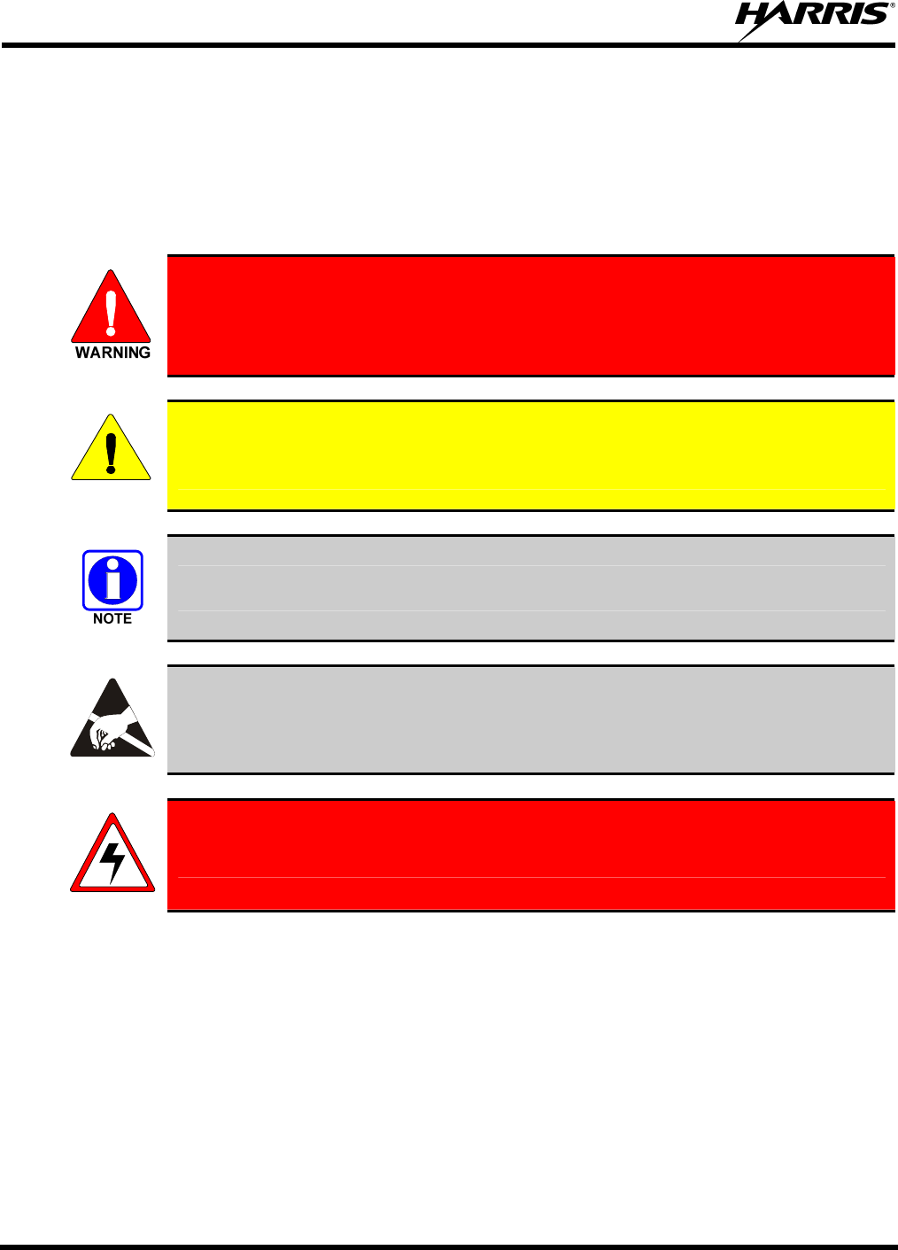
1 SAFETY CONVENTIONS
The following conventions are used throughout this manual to alert the user to general safety precautions
that must be observed during all phases of operation, service, and repair of this product. Failure to comply
with these precautions or with specific warning elsewhere in this manual violates safety standards of
design, manufacture, and intended use of the product. Harris Corporation assumes no liability for the
customer’s failure to comply with these standards.
The WARNING symbol calls attention to a procedure, practice, or the like, which, if
not correctly performed or adhered to, could result in personal injury. Do not
proceed beyond a WARNING symbol until the conditions identified are fully
understood or met.
CAUTION
The CAUTION symbol calls attention to an operating procedure, practice, or the like,
which, if not performed correctly or adhered to, could result in damage to the equipment
or severely degrade the equipment performance.
The NOTE symbol calls attention to supplemental information, which may improve
system performance or clarify a process or procedure.
The ESD symbol calls attention to procedures, practices, or the like, which could expose
equipment to the effects of Electro-Static Discharge. Proper precautions must be taken to
prevent ESD when handling circuit modules.
WARNING - The electrical hazard symbol indicates there is an electrical hazard
present.
MM-013994-001, Rev. Ap1
13
2 SAFETY TRAINING INFORMATION
The Harris P7300 portable radio generates RF electromagnetic energy during
transmit mode. This radio is designed for and classified as “Occupational Use
Only,” meaning it must be used only during the course of employment by
individuals aware of the hazards and the ways to minimize such hazards. This
radio is NOT intended for use by the “General Population” in an uncontrolled
environment.
The P7300 portable radio has been tested and complies with the FCC RF exposure limits for
“Occupational Use Only.” In addition, this Harris radio complies with the following Standards and
Guidelines with regard to RF energy and electromagnetic energy levels and evaluation of such levels for
exposure to humans:
• FCC OET Bulletin 65 Edition 97-01 Supplement C, Evaluating Compliance with FCC Guidelines for
Human Exposure to Radio Frequency Electromagnetic Fields.
• American National Standards Institute (C95.1 – 1992), IEEE Standard for Safety Levels with Respect
to Human Exposure to Radio Frequency Electromagnetic Fields, 3 kHz to 300 GHz.
• American National Standards Institute (C95.3 – 1992), IEEE Recommended Practice for the
Measurement of Potentially Hazardous Electromagnetic Fields – RF and Microwave.
2.1 RF EXPOSURE GUIDELINES
CAUTION
To ensure that exposure to RF electromagnetic energy is within the FCC allowable
limits for occupational use, always adhere to the following guidelines:
• DO NOT operate the radio without a proper antenna attached, as this may damage the radio and may
also cause the FCC RF exposure limits to be exceeded. A proper antenna is the antenna supplied with
this radio by Harris or an antenna specifically authorized by Harris for use with this radio. (Refer to
Table 6-1.)
• DO NOT transmit for more than 50% of total radio use time (“50% duty cycle”). Transmitting more
than 50% of the time can cause FCC RF exposure compliance requirements to be exceeded. The radio
is transmitting when the “TX” indicator appears in the display. The radio will transmit by pressing the
“PTT” (Push-To-Talk) button.
• Always transmit using low power when possible. In addition to conserving battery charge, low power
can reduce RF exposure.
• ALWAYS use Harris authorized accessories (antennas, batteries, belt clips, speaker/mics, etc). Use of
unauthorized accessories may cause the FCC Occupational/Controlled Exposure RF compliance
requirements to be exceeded. (Refer to Table 2-1.)
MM-013994-001, Rev. Ap1
14
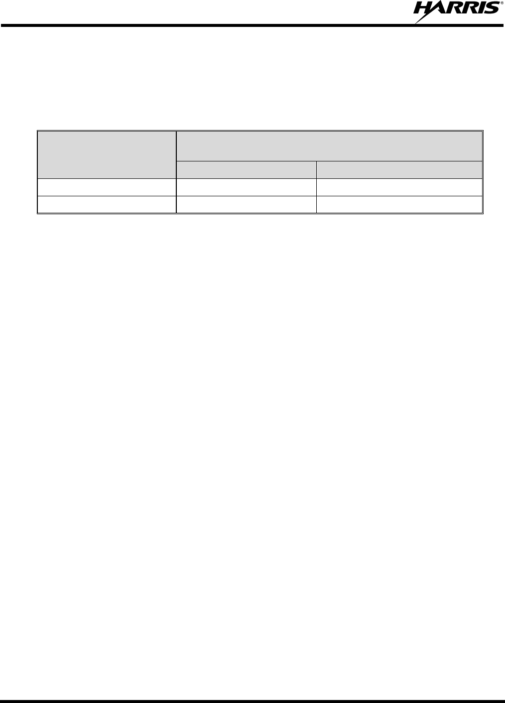
• As noted in Table 2-1, ALWAYS keep the device and its antenna AT LEAST 1.1 cm (0.43 inches)
from the body and at least 2.5 cm (1.0 inch) from the face when transmitting to ensure FCC RF
exposure compliance requirements are not exceeded. However, to provide the best sound quality to
the recipients of your transmission, Harris recommends you hold the microphone at least 5 cm (2
inches) from mouth, and slightly off to one side.
Table 2-1: RF Exposure Compliance Testing Distances
TESTED DISTANCES
(worst case scenario)
RADIO FREQUENCY
Body Face
450-512 MHz 1.1 cm 2.5 cm
700/800 MHz 1.1 cm 2.5 cm
The information in this section provides the information needed to make the user aware of RF exposure,
and what to do to assure that this radio operates within the FCC RF exposure limits of this radio.
2.2 ELECTROMAGNETIC INTERFERENCE/COMPATIBILITY
During transmissions, this Harris radio generates RF energy that can possibly cause interference with
other devices or systems. To avoid such interference, turn off the radio in areas where signs are posted to
do so. DO NOT operate the transmitter in areas that are sensitive to electromagnetic radiation such as
hospitals, aircraft, and blasting sites.
MM-013994-001, Rev. Ap1
15
3 OPERATING TIPS
Antenna location and condition are important when operating a portable radio. Operating the radio in low
lying areas or terrain, under power lines or bridges, inside of a vehicle or in a metal framed building can
severely reduce the range of the unit. Mountains can also reduce the range of the unit.
In areas where transmission or reception is poor, some improvement may be obtained by ensuring that the
antenna is vertical. Moving a few yards in another direction or moving to a higher elevation may also
improve communications. Vehicular operation can be aided with the use of an externally mounted
antenna.
Battery condition is another important factor in the trouble free operation of a portable radio. Always
properly charge the batteries.
3.1 EFFICIENT RADIO OPERATION
Keep the antenna in a vertical position when receiving or transmitting a message.
Do not hold the antenna when receiving a message and, especially, do not hold when transmitting a
message.
Do NOT hold onto the antenna when the radio is powered on!
3.1.1 Antenna Care and Replacement
Do not use the portable radio with a damaged or missing antenna. A minor burn
may result if a damaged antenna comes into contact with the skin. Replace a
damaged antenna immediately. Operating a portable radio with the antenna missing
could cause personal injury, damage the radio, and may violate FCC regulations.
Use only the supplied or approved antenna. Unauthorized antennas, modifications,
or attachments could cause damage to the radio unit and may violate FCC
regulations. (Refer to Table 6-1.)
3.1.2 Electronic Devices
CAUTION
RF energy from portable radios may affect some electronic equipment. Most modern
electronic equipment in cars, hospitals, homes, etc. is shielded from RF energy. However,
in areas in which you are instructed to turn off two-way radio equipment, always observe
the rules. If in doubt, turn it off!
MM-013994-001, Rev. Ap1
16
3.1.3 Aircraft
• Always turn off a portable radio before boarding any aircraft!
• Use it on the ground only with crew permission.
• DO NOT use while in-flight!!
3.1.4 Electric Blasting Caps
To prevent accidental detonation of electric blasting caps, DO NOT use two-way
radios within 1000 feet of blasting operations. Always obey the "Turn Off Two-Way
Radios" signs posted where electric blasting caps are being used. (OSHA Standard:
1926.900)
3.1.5 Potentially Explosive Atmospheres
Areas with potentially explosive atmospheres are often, but not always, clearly
marked. These may be fuelling areas, such as gas stations, fuel or chemical transfer
or storage facilities, and areas where the air contains chemicals or particles, such as
grain, dust, or metal powders.
Sparks in such areas could cause an explosion or fire resulting in bodily injury or
even death.
Turn OFF two-way radios when in any area with a potentially explosive atmosphere.
It is rare, but not impossible that a radio or its accessories could generate sparks.
MM-013994-001, Rev. Ap1
17
4 BATTERIES
The P7300 series portable radios use rechargeable, recyclable Nickel Cadmium (NiCd), Nickel Metal
Hydride (NiMH), or Lithium Ion (Li Ion) batteries. Please read carefully, the battery information
provided, to maximize the useful life of each type of battery.
Do not disassemble or modify Lithium Ion battery packs. The Lithium Ion battery
packs are equipped with built-in safety and protection features. Should these
features be disabled or tampered with in any way, the battery pack can leak acid,
overheat, emit smoke, burst, and/or, ignite.
If the battery is ruptured or is leaking electrolyte that results in skin or eye contact
with the electrolyte, immediately flush the affected area with water. If the battery
electrolyte gets in the eyes, flush with water for 15 minutes and consult a physician
immediately.
4.1 CONDITIONING BATTERY PACKS
4.1.1 Conditioning NiMH Battery Packs
Condition a new NiMH battery before putting into use. This also applies to rechargeable NiMH batteries
that have been stored for long periods (weeks, months, or longer). Conditioning requires fully charging
and fully discharging the battery three (3) times using the tri-chemistry charger. The first time the battery
is put into the charger, this unit will condition Nickel-based battery packs by automatically charging and
discharging (cycling) the battery. Refer to the appropriate charger manual for details.
CAUTION
Failure to properly condition NiMH battery packs before initial use will result in
shortened performance by the battery.
4.1.2 Conditioning NiCd Battery Packs
A new NiCd battery does not require conditioning before use. However, Harris recommends periodically
conditioning NiCd batteries to avoid the memory effect which results when a NiCd battery is repeatedly
charged and not fully discharged, further resulting in a lower voltage and a lower capacity. Fortunately,
both nominal voltage and capacity are restored through battery conditioning.
Conditioning requires fully charging and fully discharging the battery three (3) times using the tri-
chemistry charger. The first time the battery is put into the charger, this unit will condition Nickel-based
battery packs by automatically charging and discharging (cycling) the battery. Refer to the appropriate
charger manual for details.

MM-013994-001, Rev. Ap1
18
CAUTION
Always use Harris authorized chargers and conditioners. Use of unauthorized chargers
and conditioners may void the warranty.
4.1.3 Additional Information
For more information regarding the proper care of portable radio batteries or establishing a battery
maintenance program, refer to ECR-7367 which may be ordered by calling toll free 1-800-368-3277, then
select option 7.
4.2 CHARGING BATTERY PACKS
Battery chargers are available from Harris with nominal charge times. Combinations include single and
multi-position charge units.
Harris chargers are specifically designed for charging nickel-based and lithium ion battery packs. The
chargers are chemistry-specific for the battery packs and automatically adjust the charging profiles
accordingly. Refer to the appropriate charger manual for specific operating instructions.
4.2.1 Charging Guidelines
Observe the following guidelines when charging a battery pack:
• Avoid high temperature during charging.
• Discontinue use if the charger is overheating.
• Only charge Harris battery packs using a charger approved for use by Harris.
• Do not leave batteries in the charger indefinitely. For best results, leave the battery in the charger for
two to six hours after the Green Ready LED comes on. Then place the battery pack into service and
fully discharge (as indicated by the radio low battery warning) before re-charging.
If any faults are encountered while charging the battery pack, consult the charger’s manual to determine
the cause and possible corrective action.
4.3 BATTERY PACK USAGE
Both Nickel-based and Lithium ion batteries vary in capacity and life cycle. For instance, NiCd batteries
have a longer life cycle than NiMH batteries whereas NiMH batteries have a larger capacity. However,
both Nickel-based and Lithium ion type batteries require basic usage guidelines be followed in order to
optimize the battery runtime or shift life.
4.3.1 Usage Guidelines
The following guidelines will help optimize the battery runtime or shift life:
• Ensure Nickel-based battery packs are fully discharged (as indicated by the radio low battery
warning) before re-charging. Full discharge is not required for Lithium Ion battery packs.
• Periodically condition Nickel-based battery packs. The frequency should be determined based on
usage patterns (refer to ECR-7367). If the battery is fully discharged (to radio Low Battery warning)
during routine use, the frequency of conditioning may be reduced. Lithium Ion batteries do not suffer
from memory-effect and therefore do not require conditioning.
MM-013994-001, Rev. Ap1
19
Do not leave any Harris rechargeable batteries in a charger for more than a few days.
4.4 CHANGING THE BATTERY PACK
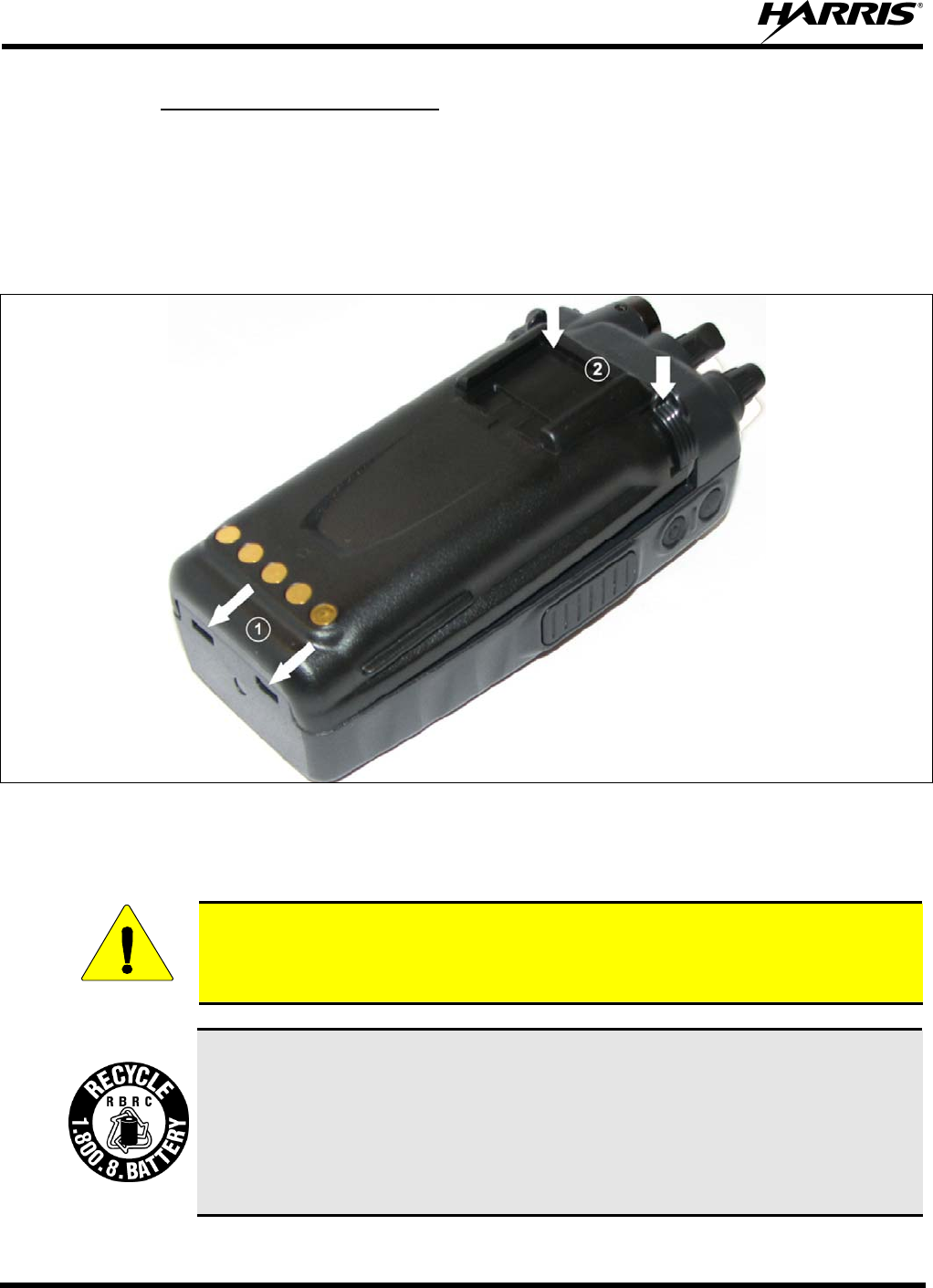
4.4.1 Removing the Battery Pack
Make sure the power to the radio is turned OFF.
CAUTION
Although the P7300 has been designed to tolerate changing the battery pack without
turning power off, Harris recommends turning the radio off before changing battery packs
to ensure safety and best operation.
1. Press or pull both latches on either side of the battery pack toward the bottom of the radio
simultaneously.
2. Pull the battery away from the radio.
3. Remove the battery pack from the radio.
Figure 4-1: Removing the Battery Pack
MM-013994-001, Rev. Ap1
20
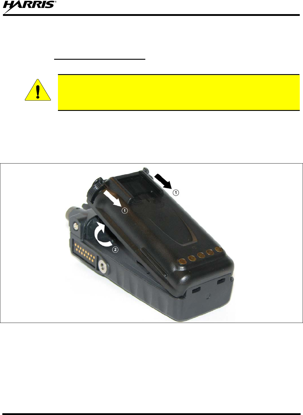
4.4.2 Attaching the Battery Pack
Make sure the power to the radio is turned OFF.
1. Align the tabs at each side on the bottom of the battery pack with the slots at the bottom of the battery
cavity .
2. Push the top of the battery pack down until the latches click to attach the battery to the radio.
3. Tug gently to verify that the latches are secure and the battery pack is properly attached to the radio.
Figure 4-2: Attaching the Battery Pack
4.5 BATTERY DISPOSAL
CAUTION
In no instance should a battery be incinerated. Disposing of a battery by burning will
cause an explosion.
RECHARGEABLE BATTERY PACK DISPOSAL – The product you have
purchased contains a rechargeable battery. The battery is recyclable. At the end of its
useful life, under various state and local laws, it may be illegal to dispose of this
battery into the municipal waste stream. Check with your local solid waste officials for
details in your area for recycling options or proper disposal. Canadian and U.S. users
may call Toll Free 1-800-8-BATTERY® for information and/or procedures for
returning rechargeable batteries in your locality.

MM-013994-001, Rev. Ap1
21
PRODUCT INFORMATION

MM-013994-001, Rev. Ap1
22
5 INTRODUCTION
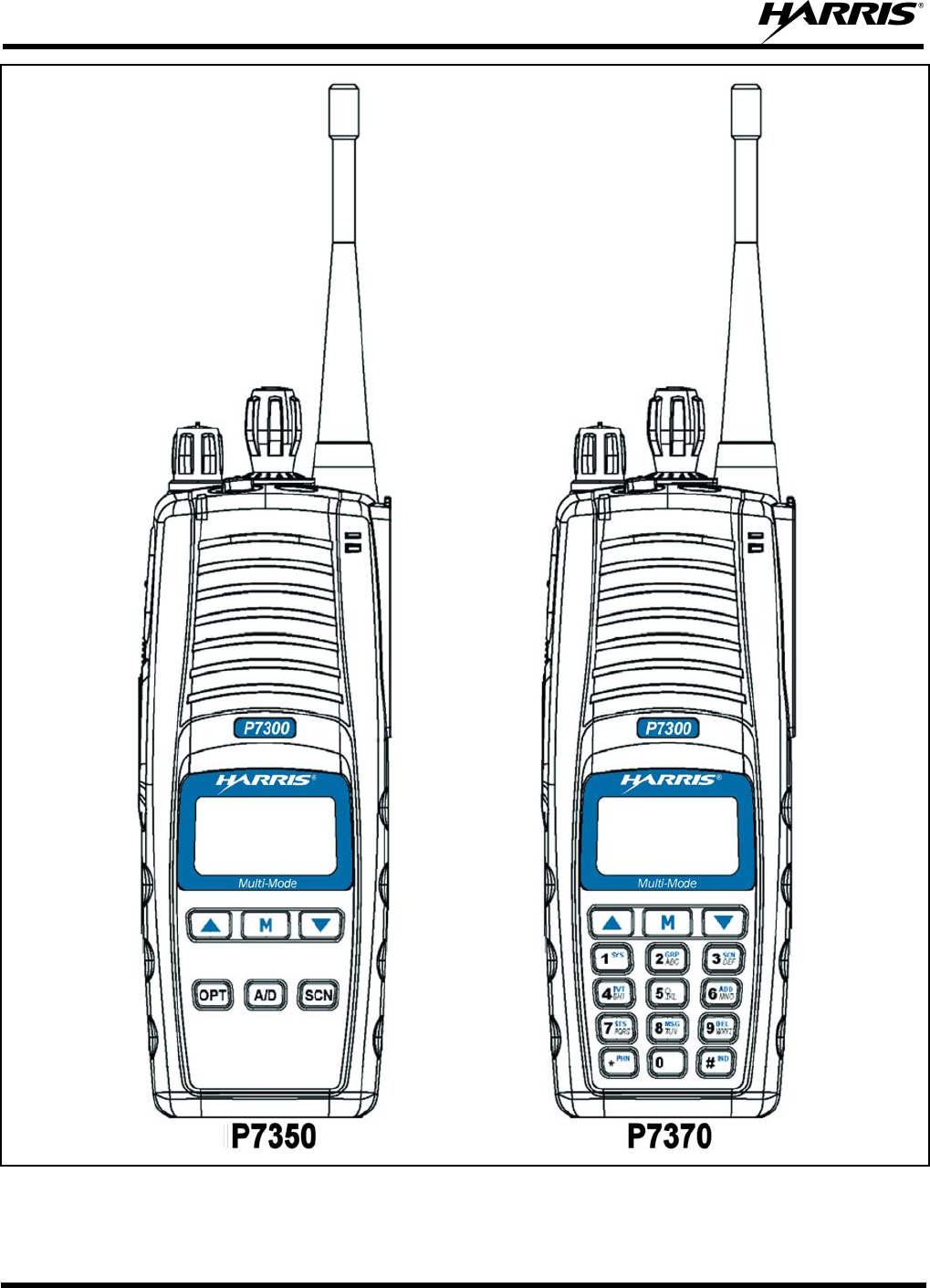
The P7300 series portable radio is available in two models: the P7350 Scan model with a limited 6-button
front-mounted keypad and the P7370 System model with a 15-button DTMF front-mounted keypad. The
UHF P7300 portable radio delivers end-to-end encrypted digital voice and IP data communications. It is
designed to support multiple operating modes including:
• EDACS® (Enhanced Digital Access Communications System) or ProVoice™ Trunked mode
• P25 Trunked Mode
• P25 Digital Conventional Mode
• Conventional Analog mode
The P7300 portables can include all of these modes or just one. Additional modes of operation can be
added with software updates.
The P7300 supports a full range of advanced digital trunking features, including voice group calls,
priority scanning, emergency calls, late call entry, and dynamic reconfiguration. It performs autonomous
roaming for wide area applications. High quality voice coding and robust audio components assure
speech clarity.
In the trunked modes, the user selects a communications “operating” system (i.e., EDACS, ProVoice, or
P25) and group. While communicating in a trunked mode, channel selection is transparent to the user and
is controlled via digital communication with the system controller (e.g., a CSD in an EDACS system).
This provides advanced programmable features and fast access to communication channels.
In Conventional Analog mode, the user selects a channel and communicates directly on that channel. A
channel is a transmit/receive radio frequency pair.
The exact operation of the radio will depend on the operating mode, the radio’s programming, and the
particular radio system. Most features described in this manual can be enabled through programming.
Consult your System Administrator for the particular features programmed into your P7300. Then refer
to the corresponding section(s) within this manual for feature and operation information.
5.1 WATER RESISTANCE
The P7300 series portable radios operate reliably even under adverse conditions. These radios meet MIL-
STD-810F specifications for wind driven rain, humidity, and salt fog.
MM-013994-001, Rev. Ap1
23
6 OPTIONS AND ACCESSORIES
Table 6-1 lists the Options and Accessories tested for use with the P7300 series portable radios.
Refer to the maintenance manual or to Harris Products and Services Catalog for a complete list of options
and accessories, including those items that do not adversely affect the RF energy exposure.
Always use Harris authorized accessories (antennas, batteries, belt clips,
speaker/mics, etc). Use of unauthorized accessories may cause the FCC
Occupational/Controlled Exposure RF compliance requirements to be exceeded.
(Refer to Table 2-1.)
CAUTION
Always use the correct options and accessories (battery, antenna, speaker/mic, etc.) for the
radio. Intrinsically safe options must be used with intrinsically safe radios. (Refer to Table
6-1.)
Table 6-1: Options and Accessories
DESCRIPTION PART NUMBER
ANTENNAS
Helical Stub 470-512 MHz KRE 101 1219/14
¼ λ Whip 440-512 MHz KRE 101 1223/12
BATTERIES (IMMERSION-RATED)
7.5V Nickel Cadmium (NiCd) Battery, Immersible, non-<IS> BT-023406-001
7.5V Nickel Cadmium (NiCd) Battery, Immersible, <IS> BT-023406-002
7.5V Nickel Metal Hydride (NiMH) Battery, Immersible, non-<IS> BT-023406-003
7.5V Nickel Metal Hydride (NiMH) Battery, Immersible, <IS> BT-023406-004
7.5V Lithium Ion (Li Ion) Battery, Immersible, non-<IS> BT-023406-005
7.5V Lithium Ion (Li Ion) Battery, Immersible, <IS> BT-023406-006
MISCELLANEOUS ACCESSORIES
Speaker Mic without Antenna (cc) provision, <IS> MC-023933-001
Speaker Mic with Antenna (cc) provision, <IS> MC-023933-002
Earphone for Speaker Mic <IS> LS103239V1
DROP SHIP AUDIO ACCESSORIES
Earphone Kit, Black EA-009580-001
Earphone Kit, Beige EA-009580-002
2-Wire Kit, Palm Mic, Black EA-009580-003
2-Wire Kit, Palm Mic, Beige EA-009580-004
3-Wire Kit, Mini-Lapel Mic, Black EA-009580-005
3-Wire Kit, Mini-Lapel Mic, Beige EA-009580-006
Explorer Headset with PTT EA-009580-007
Lightweight Headset Single Speaker with PTT EA-009580-008
Breeze Headset with PTT EA-009580-009
Headset, Heavy Duty, N/C Behind-the-Head, with PTT EA-009580-010
Ranger Headset with PTT EA-009580-011
Skull Mic with Body PTT and Earcup EA-009580-012
Headset, Heavy Duty, N/C Over-the-Head, with PTT EA-009580-013
Throat Mic with Acoustic Tube and Body PTT EA-009580-014

MM-013994-001, Rev. Ap1
24
DESCRIPTION PART NUMBER
Throat Mic with Acoustic Tube, Body PTT, and Ring PTT EA-009580-015
Breeze Headset with PTT and Pigtail Jack EA-009580-016
Hurricane Headset with PTT EA-009580-017
Hurricane Headset with PTT and Pigtail Jack EA-009580-018
CARRYING CASE ACCESSORIES
P7300 Black Nylon Case with Belt Loop Kit, consists of:
P7300 Black Nylon Case with Retaining Strap
and Leather Belt Loop
Kit: KT-016201-001, incl:
FM-016199-001
CC-014527
P7300 Orange Nylon Case with Belt Loop Kit, consists of:
P7300 Orange Nylon Case with Retaining Strap
and Leather Belt Loop
Kit: KT-016201-002, incl:
FM-016199-002
CC-014527
P7300 Leather Case with Belt Loop Kit, consists of:
P7300 Leather Case with Retaining Strap
(w/o Shoulder Strap D-Rings), Swivel Mount
and Leather Belt Loop
Kit: KT-016201-003, incl:
FM-016199-003
KRY 101 1608/2
CC-014527
P7300 Leather Case with Shoulder Strap Kit, consists of:
P7300 Leather Case with Retaining Strap D-Rings
with Retaining Strap, Swivel Mount
Shoulder Strap
Kit: KT-016201-004, incl:
FM-016199-004
KRY 101 1608/2
CC-014524-001
Short Leather Retaining Strap (for use with Shoulder Strap application) CC-014524-002
Swivel Mount and Belt Loop KRY 101 1608/2
KRY 101 1609/1
Metal Belt Clip (standard) CC23894
Metal Belt Clip (alternate) CC-011318
“T” Strap Holder KRY 101 1656/1

MM-013994-001, Rev. Ap1
25
7 USER INTERFACE
This section describes the primary user interface; the buttons, knob controls, indicators, and display.
MM-013994-001, Rev. Ap1
26
Figure 7-1: P7300 Portable Radio
MM-013994-001, Rev. Ap1
27
7.1 CONTROLS
7.1.1 Buttons and Knobs
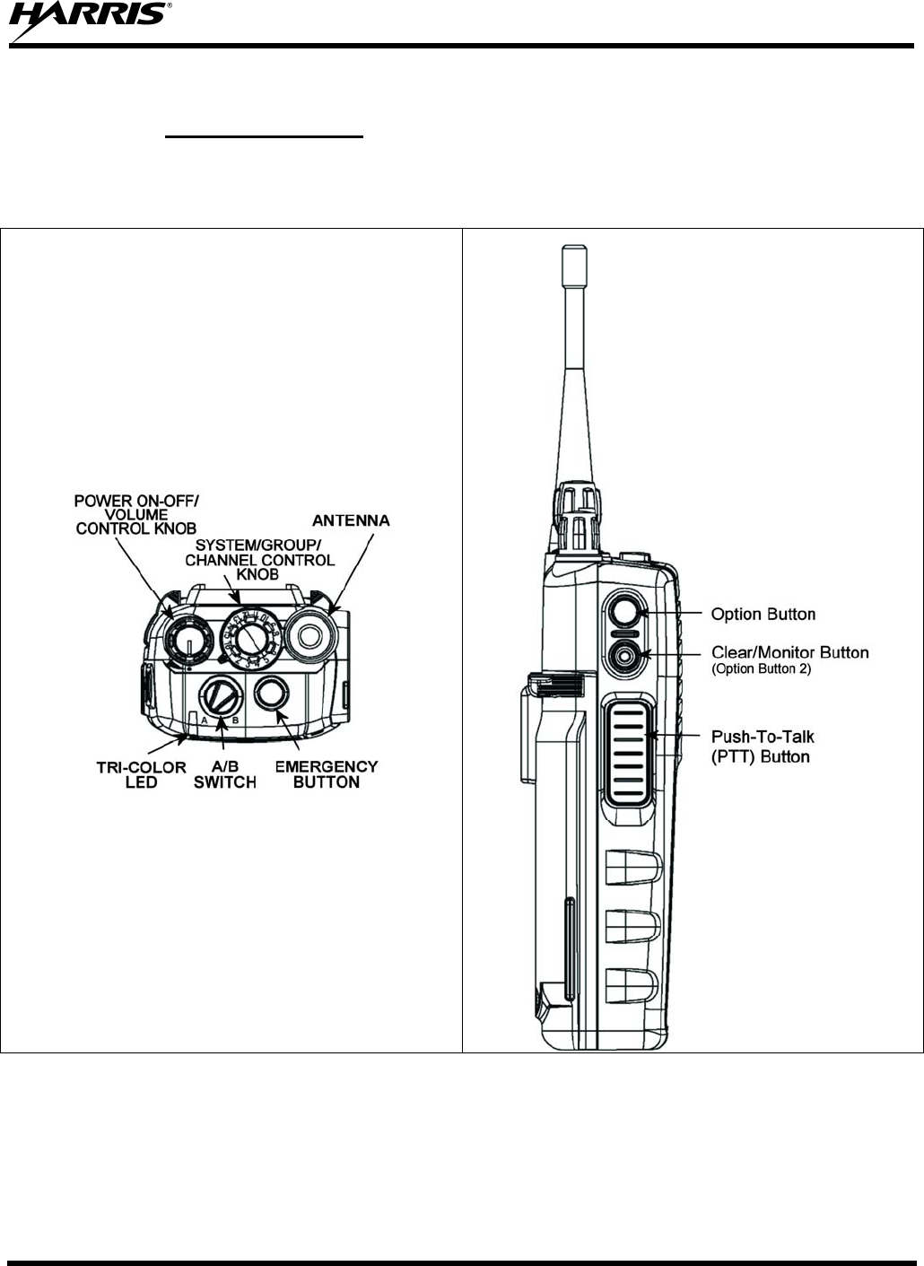
The P7300 portable radios feature two rotary control knobs, an emergency button, and a dual-position
A/B switch located on the top of the radio (Figure 7-2). The Push-To-Talk (PTT) button and two option
buttons are located on the side (Figure 7-3).
Figure 7-2: Top View Figure 7-3: Side View
The functions of the button and knob controls vary depending on the mode of operation. The primary
functions of the button and knob controls when in the EDACS mode of operation are listed in the
following paragraphs. The functions while in other modes are discussed in the specific sections.

MM-013994-001, Rev. Ap1
28
POWER ON/OFF-VOLUME
CONTROL KNOB Applies power to the radio and adjusts audio volume.
Rotating the control clockwise applies power to the radio. A single
alert tone (if enabled through programming) indicates the radio is
operational.
Rotating the control clockwise increases the volume level. Minimum
volume levels may be programmed into the radio to prevent missed
calls due to a low volume setting. While adjusting the volume, the
display will momentarily indicate the volume level (i.e., VOL=31). The
volume range is from a minimum programmed level of zero (displayed
as OFF in the display) up to 40, which is the loudest level.
SYSTEM/GROUP/CHANNEL
CONTROL KNOB Used to select groups/channels. This is a 16-position rotary knob.
Note: A mechanical stop, used to limit the number of accessible
positions, is shipped with the radio but must be installed. To install the
mechanical stop, remove the System/Group/Channel control knob,
loosen the set screw on the System/Group/Channel control knob metal
base (using a 1.27 mm hex wrench), and remove the
System/Group/Channel control knob metal base. Replace the 16
channel ring with the channel stop ring located at the desired channel.
Re-install the System/Group/Channel control knob metal base, tighten
the set screw, and re-install the System/Group/Channel control knob.
EMERGENCY/HOME BUTTON Automatically selects the pre-programmed Group/System by pressing
and holding for a programmed duration. It can also be used to declare
an emergency by pressing and holding for a programmed duration. The
button must be pre-programmed for either operation, but not both.
PUSH-TO-TALK (PTT) BUTTON The PTT button must be pressed before voice transmission begins.
OPTION BUTTON Activates one of a number of programmable software options selected
during PC programming. Programmable options include hi/low power
settings, keypad lock, LCD contrast, LCD and keypad back lighting.
CLEAR/MONITOR BUTTON
(OPTION BUTTON 2) Exits the current operation (removing all displays associated with it)
and returns the radio to the selected talk group. Terminates individual
and telephone interconnect calls.
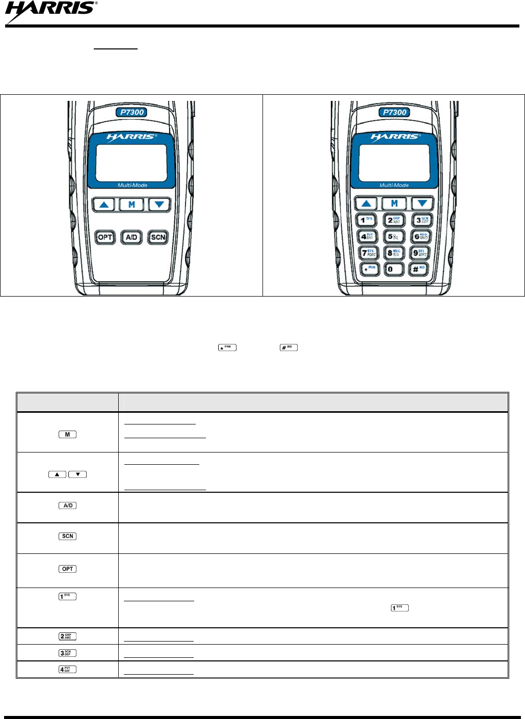
MM-013994-001, Rev. Ap1
29
7.1.2 Keypad
The front mounted keypad of the P7350 “Scan” model has six buttons and P7370 “System” model has 15
buttons. Refer to Figure 7-4 and Figure 7-5, respectively.
Figure 7-4: P7350 “Scan” Model Front Panel Figure 7-5: P7370 “System” Model Front Panel
Alpha-numeric character entry is the secondary function of most of the P7300 keypad keys in the EDACS
mode of operation. In addition, the (*) and (#) keys are also available. The primary and
secondary functions of each key, where applicable, are described in Table 7-1 and the following section.
Table 7-1: P7300 Front Keypad Functions
KEY FUNCTION
Primary Function: Accesses the pre-stored menu.
Secondary Function: Activates a selected item within the menu. This is similar to an “Enter”
key.
Primary Function: Allows the user to scroll through available systems, groups, or channels,
depending on personality programming.
Secondary Function: Changes the selection for an item within a list.
(P7350 only) In EDACS and Conventional Analog modes, Adds/Deletes selected groups or channels from
SCAN list of the currently selected system.
(P7350 only) In EDACS and Conventional Analog modes, toggles SCAN operation ON and OFF.
(P7350 only) In EDACS and Conventional Analog modes, activates one of any programmable software
options selected during the PC programming, including: high/low TX power and talkaround.
Primary function: Selects a specific system. If the rotary knob is used to select the system
and more than 16 systems are programmed in the radio, the key is used to select
additional banks (groupings) of systems.
Primary function: Selects a specific group.
Primary function: Turns the Scan operation ON and OFF.
Primary function: Enables or disables Private Mode for the system/group/channel displayed.
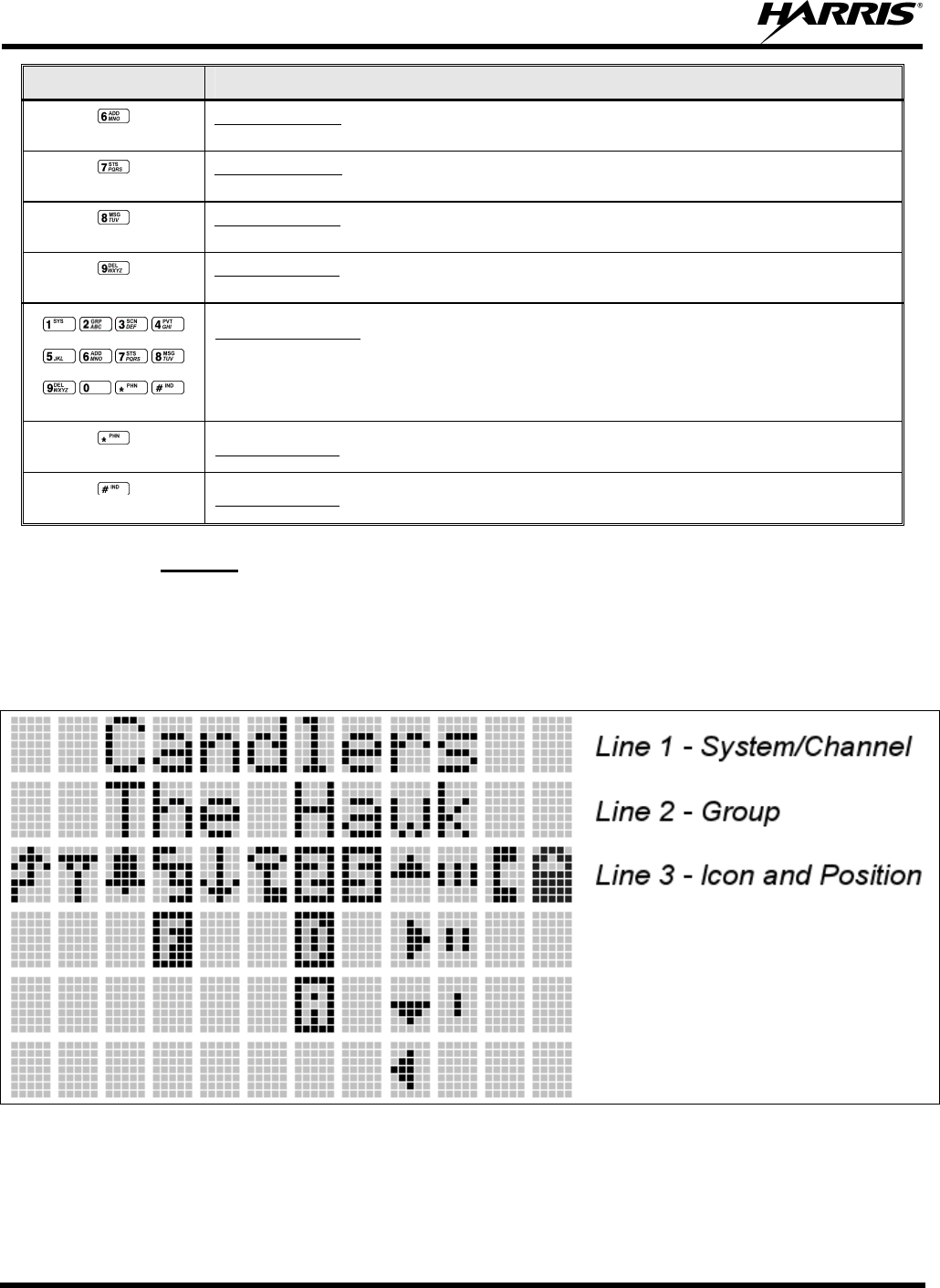
MM-013994-001, Rev. Ap1
30
KEY FUNCTION
Primary function: Adds groups or channels from the currently selected system to the Scan
list.
Primary function: Status key. Access to the status list (0-9). The Status key permits the
transmission of a pre-programmed status message to an EDACS site.
Primary function: Message key. Access to the message list (0-9). The Message key permits
the transmission of a pre-programmed message to an EDACS site.
Primary function: Deletes selected groups or channels of the currently selected system from
the Scan list.
(P7370 Only)
Secondary function: In EDACS mode the secondary function of these keys is much as a
typical DTMF telephone pad 0-9, *, and # keys; and are used to place telephone
interconnect and individual (unit-to-unit) calls. (See individual listings for primary
functions.)
(P7370 Only) Primary function: In EDACS mode, initiates telephone interconnect calls.
(P7370 Only) Primary function: In EDACS mode, initiates individual, unit-to-unit calls.
7.1.3 Display
The P7300 display is made up of 3 lines. Lines 1 and 2 contain twelve alpha-numeric character blocks
each. The 3rd line also contains twelve blocks, each used to display radio status icons. If programmed, the
display backlighting will illuminate upon power up or when radio controls are operated. Specific display
characteristics will be discussed in following sub-sections.
Figure 7-6: P7300 Radio Display
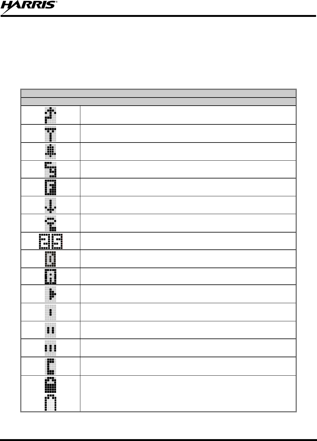
MM-013994-001, Rev. Ap1
31
7.1.3.1 Radio Status Icons
Status Icons represent various operating characteristics of the radio and appear on the third line of the
display. Each of the icons will be discussed in further detail in the corresponding modes of operation;
EDACS and Conventional icons will be discussed in the EDACS or Conventional Operation sections, and
P25 icons will be discussed in the P25 Operation section.
Table 7-2: Status Icons Descriptions
STATUS ICON DESCRIPTIONS
EDACS, CONVENTIONAL, AND P25 ICONS
Steady – during all radio transmissions. Appears in the 1st position of the display.
Steady – “Busy” transmitting or receiving. Appears in the 2nd position of the display.
Flashing – call queued.
Steady – T99 Mode enabled. Appears in the 3rd position of the display.
Steady – Channel Guard enabled. Appears in the 4th position of the display.
If icon is not visible – Channel Guard is disabled.
Steady – trunked system in Failsoft™ mode. Appears in the 4th position of the display.
Steady – transmit at low power. Appears in the 5th position of the display.
If icon is not visible – transmit at high power.
Steady – transmit in encrypt mode. Appears in the 6th position of the display.
Flashing – receiving an encrypted call.
Steady – Indicates the current channel is set up as a Project 25 (P25) channel. Appears in the
7th and 8th positions of the display.
Steady – Indicates the current channel is set up as a ProVoice channel. Appears in the 7th
position of the display.
Steady – Indicates the current channel is set up as an analog channel. Appears in the 7th
position of the display.
Animated (rotates clockwise) – scan mode enabled. Appears in the 9th position of the display.
If icon is not visible – scan is disabled.
Steady – priority 1 group or channel. Appears in the 10th position of the display.
Steady – priority 2 group or channel. Appears in the 10th position of the display.
Steady – group or channel in scan list. Appears in the 10th position of the display.
Steady – special call mode (individual or telephone). Appears in the 11th position of the
display.
Steady – battery charge indicators. Appear in the 12th position of the display.
Flashing – Low battery indicator.
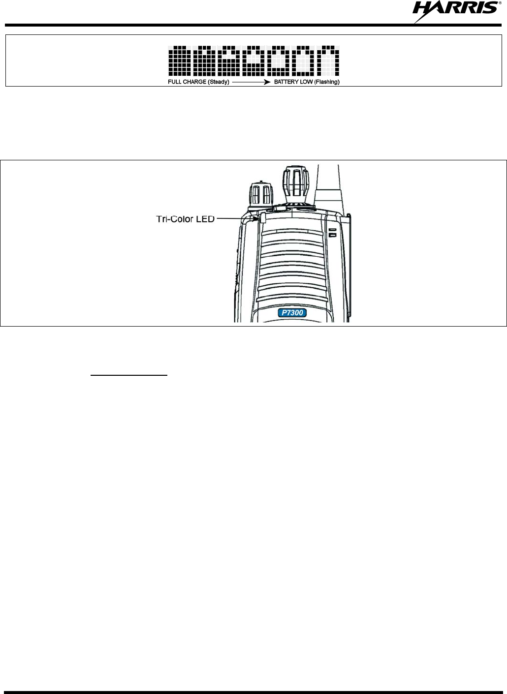
MM-013994-001, Rev. Ap1
32
Figure 7-7: Full Cycle Battery Charge Indicator
The battery charge indicators illustrate approximate level only, based on battery voltage. Refer to Figure
7-7.
Figure 7-8: Tri-Color LED
7.1.4 Tri-Color LED
The Tri-Color LED changes color to indicate radio status and is visible from both the front and top of the
radio (see Figure 7-2). In addition, the mode of operation may also help determine what the color of the
LED represents.
In EDACS, Conventional, or P25 modes
Green: Receiving
Red: Transmitting Unencrypted
Orange: Transmitting Encrypted
7.2 UNIVERSAL DEVICE CONNECTOR
The Universal Device Connector (UDC) provides connections for external accessories such as a headset,
a speaker-microphone, audio test box, audio test cables, and programming cables. The UDC is located on
the right side of the radio, opposite the PTT Button. The UDC facilitates programming and testing the
radio. The UDC pins perform different functions depending on the accessory attached to the UDC.

MM-013994-001, Rev. Ap1
33
Figure 7-9: P7300 15-Pin Universal Device Connector

MM-013994-001, Rev. Ap1
34
EDACS OPERATION

MM-013994-001, Rev. Ap1
35
8 EDACS OPERATION
8.1 CONTROLS
The radio features two rotary control knobs and an emergency button mounted on the top of the radio.
Push-To-Talk and option buttons are mounted on the side. The front mounted keypad has six buttons on
the P7350 Scan model and 15 buttons on the P7370 System Radio.
8.1.1 Buttons and Knobs
This section describes the primary function of the button and knob controls (see Figure 7-2 and Figure
7-3). Other functions associated with these controls are detailed in later sections.
POWER ON/OFF-VOLUME
CONTROL KNOB Applies power to and adjusts the receiver’s volume. Rotating the
control clockwise applies power to the radio. A single alert tone (if
enabled through programming) indicates the radio is operational.
Rotating the control clockwise increases the volume level. Minimum
volume levels may be programmed into the radio to prevent missed
calls due to a low volume setting. While adjusting the volume the
display will momentarily indicate the volume level (i.e., VOL=31). The
volume range is from a minimum programmed level of zero (displayed
as OFF in the display) up to 40, which is the loudest level.
SYSTEM/GROUP/CHANNEL
CONTROL KNOB Selects systems or group/channels (depending on programming). This
is a 16-position rotary knob.
Note: A mechanical stop, which can limit the positions accessed, is
shipped with the radio but must be installed. To install the mechanical
stop, remove the System/Group/Channel control knob, loosen the set
screw on the System/Group/Channel control knob metal base (using a
1.27 mm hex wrench), and remove the System/Group/Channel control
kno
b
metal base. Replace the 16 channel ring with the channel stop ring
located at the desired channel. Reinstall the System/Group/Channel
control knob metal base, tighten the set screw, and reinstall the
System/Group/Channel control knob.
EMERGENCY/HOME BUTTON Automatically selects the pre-programmed Group/System by pressing
and holding for a programmed duration. It can also be used to declare
an emergency by pressing and holding for a programmed duration. The
button must be pre-programmed for either operation, but not both.
PTT BUTTON PTT must be pressed before voice transmission begins. In trunked mode
the radio’s ID is transmitted upon depression of the PTT button.
OPTION BUTTON Activates one of a number of programmable software options selected
during PC programming. Programmable options include hi/low power
settings, keypad lock, LCD contrast, LCD and keypad back lighting.
CLEAR/MONITOR BUTTON
OPTION BUTTON 2 Exits the current operation (removing all displays associated with it)
and returns the radio to the selected talk group. Terminates individual
and telephone interconnect calls.
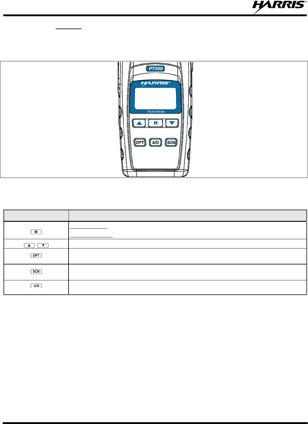
MM-013994-001, Rev. Ap1
36
8.1.2 Keypad
The keys on the keypad have special functions and are labeled using a symbol or abbreviated word
describing its primary function. Alpha-numeric entry is a secondary function of the keys. Each key is
described in the following subsections.
Figure 8-1: P7350 “Scan” Radio Front Panel
Table 8-1: P7350 Keypad Functions
KEY FUNCTION
Primary Function: Accesses the pre-stored menu.
Secondary Function: Activates a selected item within the menu. This is similar to an “Enter” key.
Scrolls thru available menu items.
(P7350 only) Activates one of any programmable software options selected during the PC programming, including:
high/low TX power and talkaround.
(P7350 only) Toggles SCAN operation ON and OFF.
(P7350 only) Adds/Deletes selected groups or channels from SCAN list of the currently selected system.
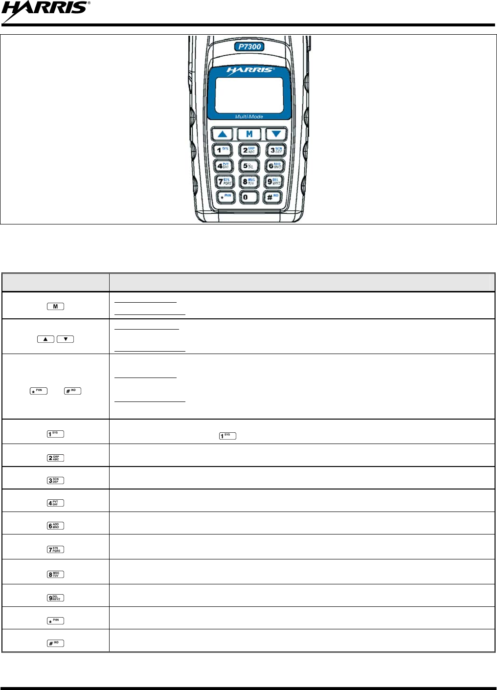
MM-013994-001, Rev. Ap1
37
Figure 8-2: P7370 “System” Radio Front Panel
Table 8-2: P7370 Keypad Functions
KEY FUNCTION
Primary Function: Accesses the pre-stored menu.
Secondary Function: Activates a selected item within the menu. This is similar to an “Enter” key.
Primary Function: Allows the user to scroll through available systems, groups, or channels, depending on
personality programming.
Secondary Function: Changes the selection for an item within a list.
0-9,
and
Primary Function: Refer to the separate key definitions within this table.
Secondary Function: These keys function much as a typical DTMF telephone pad 0-9, *, and # keys; and
are used to place telephone interconnect and individual (unit-to-unit) calls.
Selects a specific system. If the rotary knob is used to select the system and more than 16 systems are
programmed in the radio, the key is used to select additional banks (groupings) of systems.
Selects a specific group.
Turns the Scan operation ON and OFF.
Enables or disables Private Mode for the system/group/channel displayed.
Adds groups or channels from the currently selected system to the Scan list.
Status. Access to the status list (0-9). The Status key permits the transmission of a pre-programmed status
message to an EDACS site.
Message. Access to the message list (0-9). The Message key permits the transmission of a pre-
programmed message to an EDACS site.
Deletes selected groups or channels of the currently selected system from the Scan list.
Initiates telephone interconnect calls.
Initiates individual unit-to-unit calls.
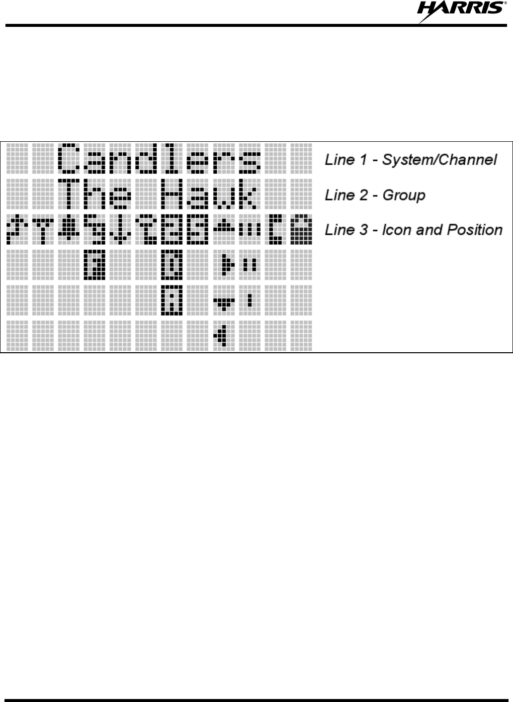
MM-013994-001, Rev. Ap1
38
8.2 DISPLAY
The radio display is made up of 3 lines (see Figure 8-3). Lines 1 and 2 contain eight alphanumeric
character blocks and are used primarily to display system and group names. Line 1 also displays radio
status messages. The 3rd line is used primarily to display radio status icons. All three lines are used to
display menu options when in the menu mode. If programmed, the display backlighting will illuminate
upon power up or when radio controls are operated.
Figure 8-3: P7300 Radio Display
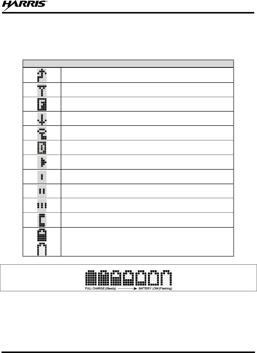
MM-013994-001, Rev. Ap1
39
8.3 RADIO STATUS ICONS
Status Icons indicate the various operating characteristics of the radio. The icons show operating modes
and conditions and appear on the third line of the display (see Table 8-3).
Table 8-3: EDACS Icon Descriptions
EDACS STATUS ICONS
Steady – during all radio transmissions. Appears in the 1st position of the display.
Steady – “Busy” transmitting or receiving. Appears in the 2nd position of the display.
Flashing – call queued.
Steady – trunked system in Failsoft™ mode. Appears in the 4th position of the display.
Steady – transmit at low power. Appears in the 5th position of the display.
If icon is not visible – transmit at high power.
Steady – transmit in encrypt mode. Appears in the 6th position of the display.
Flashing – receiving an encrypted call.
Steady – Indicates the current channel is set up as a ProVoice channel. Appears in the 7th
position of the display.
Animated (rotates clockwise) – scan mode enabled. Appears in the 9th position of the display.
If icon is not visible – scan is disabled.
Steady – priority 1 group or channel. Appears in the 10th position of the display.
Steady – priority 2 group or channel. Appears in the 10th position of the display.
Steady – group or channel in scan list. Appears in the 10th position of the display.
Steady – special call mode (individual or telephone). Appears in the 11th position of the
display.
Steady – battery charge indicators. Appear in the 12th position of the display.
Flashing – Low battery indicator.
Figure 8-4: Full Cycle Battery Charge Indicator
The battery charge indicators illustrate approximate level only, based on battery voltage. Refer to Figure
8-4.
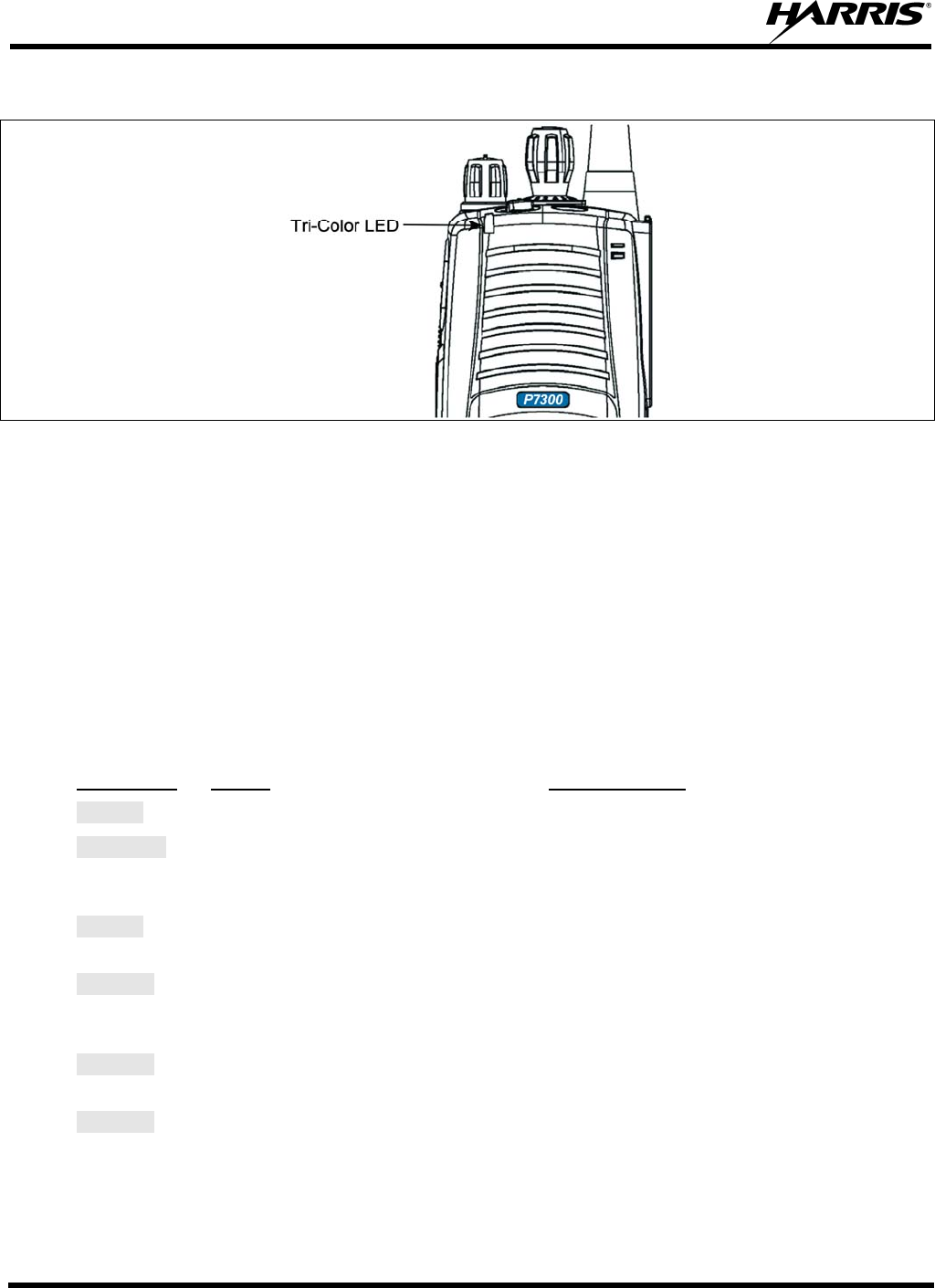
MM-013994-001, Rev. Ap1
40
8.4 TRI-COLOR LED
Figure 8-5: Tri-Color LED
The Tri-Color LED changes color to indicate radio status and is visible from both the front and top of the
radio (see Figure 8-5). The colors of the LED and the status they represent are defined below.
Green: Receiving
Red: Unencrypted transmission
Orange: Encrypted transmission
8.5 STATUS MESSAGES
During radio operation, various radio Status Messages can be displayed. The messages are described
below.
MESSAGE NAME DESCRIPTION
QUEUED Call Queued Indicates the system has placed the call in a request queue.
SYS BUSY System Busy Indicates the system is busy, no channels are currently available, the queue
is full, or an individual call is being attempted to a radio that is currently
transmitting.
DENIED Call Denied Indicates the radio or talkgroup is not authorized to operate on the selected
system and/or talkgroup.
CC SCAN Control
Channel Scan Indicates the control channel is lost and the radio has entered the Control
Channel Scan mode to search for the control channel (usually out of range
indication).
WA SCAN Wide Area
Scan Indicates the radio has entered the Wide Area Scan mode to search for a
new system (if enabled through programming).
SYSC ON System Scan
Features On Indicates the System Scan features are enabled.

MM-013994-001, Rev. Ap1
41
MESSAGE NAME DESCRIPTION
SYSC OFF System Scan
Features Off Indicates the System Scan features are disabled.
LOW BATT Low Battery Battery voltage has dropped to the point to where the radio is no longer able
to transmit. The radio will still receive calls until the battery is discharged
beyond the point of operation at which time the radio automatically shuts
down.
RXEMER Receive
Emergency Indicates an emergency call is being received. This message will be
flashing on line two.
TXEMER Transmit
Emergency Indicates an emergency call has been transmitted on this radio. This
message will be flashing on line two.
VOL=31 Volume Level Indicates the current volume level. The volume level display ranges from
OFF (muted) to 40 (loudest).
WHC Who Has
Called Indicates an individual call has been received, but not responded to. The
indicator turns OFF if the individual call mode is entered, the system is
changed, or the radio is turned off and then on again.
UNKNOWN Unknown ID Indicates an individual call is being received from an unknown ID.
8.6 ERROR MESSAGES
If either of the Error Messages shown below is displayed, the radio is programmed incorrectly or needs
servicing.
DSP ERR
ERR=XXXX
(PowerUp
only)
or DIG V x
ERR x
Where xxxx is the error code and DSP ERR or DIG V ERR is the message.
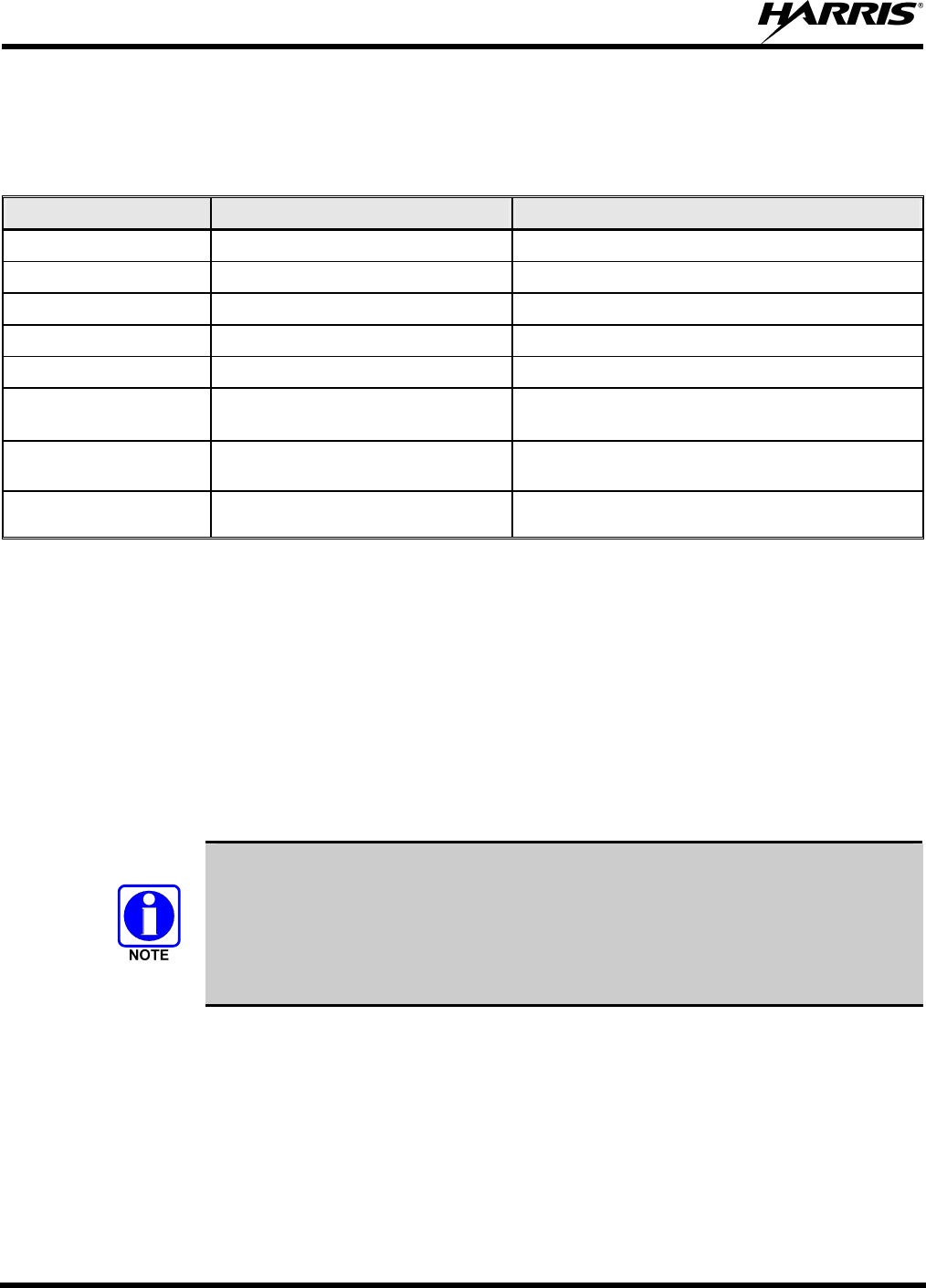
MM-013994-001, Rev. Ap1
42
8.7 ALERT TONES
The P7300 radio provides audible Alert Tones or “beeps” to indicate the various operating conditions (see
Table 8-4).
Table 8-4: Alert Tones
NAME TONE DESCRIPTION
Call Originate one short mid-pitched OK to talk after pressing the push-to-talk button
Call Queued one high-pitched Call queued for processing
Autokey one mid-pitched Queued call received channel assignment
System Busy three low-pitched System busy or unable to complete call
Call Denied one low-pitched Radio is not authorized on the system or group
Carrier Control Timer five high-pitched/one long
low-pitched
PTT depressed for maximum length of time
Low Battery one low-pitched/one short
mid-pitched
Low battery
TX Low Battery Alert one low-pitched After PTT - battery too low to transmit
8.8 TURNING ON THE RADIO
1. Power ON the radio by rotating the POWER ON-OFF/VOLUME knob clockwise. A short alert
signal (if enabled through programming) indicates the radio is ready to use.
2. The display shows the last selected system and group or a default system and group (depending on
programming).
3. Adjust the POWER ON-OFF/VOLUME knob to the desired volume level.
4. Select the desired system and group. The display indicates the current system and group names.
5. The radio is now ready to transmit and receive calls.
In the trunked environment, CC SCAN will be displayed if communication with the
system's control channel cannot be established. This may occur if, for example, the
radio is out of range of the trunking site. It may be necessary to move to another
location or select another trunking system to re-establish the control channel link for
trunked mode operations. CC SCAN is displayed on the group line until a control
channel is accessed.
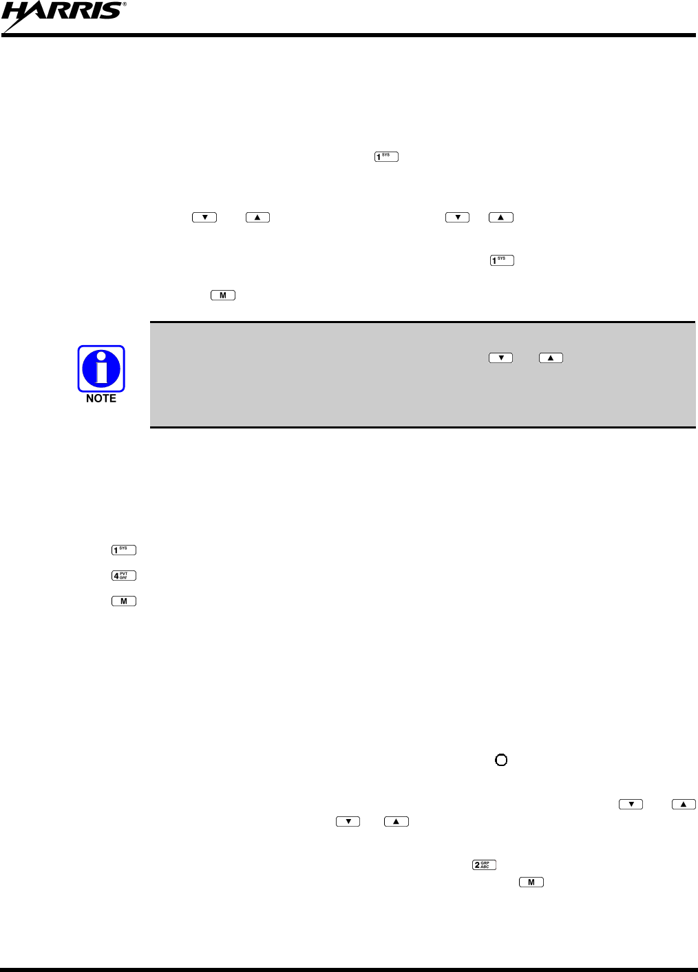
MM-013994-001, Rev. Ap1
43
8.9 SYSTEM SELECTION
METHOD 1: From the control knob: If system selection is programmed to the
System/Group/Channel control knob, select a system by turning the knob to
the desired system number position (1-16). The display registers the new
system name on line one. The button can be programmed to provide
access to a “2nd bank” of 16 system number positions (17-32).
METHOD 2: From the keypad: If system selection is programmed as the primary function
of and , select a system by pressing or to scroll through the
system list. The display registers the new system name on line one.
METHOD 3: (P7370 model radios only) Direct Access: Press to enter the system
select mode. Press the numeric key, which is mapped to the desired system.
Press . The radio will move to the selected system.
If system selection is programmed to the System/Group/Channel control knob, direct
access to systems will not be available. Pressing or will scroll through
different sets of 16 systems each (banks) if more than 16 systems are programmed into
the radio. The systems within each bank are then selectable via the
System/Group/Channel control knob as described previously in METHOD 1.
Example:
System: 1 = North Group: 1 = Group 1
2 = South 2 = Group 2
3 = East 3 = Group 3
4 = West 4 = Group 4
1. Press . (South is the currently selected system.)
2. Press . (Press 4 to select “West” system.)
3. Press . (West is the newly selected system.)
8.10 GROUP/CHANNEL SELECTION
Several methods can be used to select a new group or channel.
METHOD 1: From the Control knob: If group selection is programmed to the System/Group/Channel
control knob, select a group by turning the System/Group/Channel control knob to the
desired group number position. The display registers the new group name on line two.
If the knob is moved to a position greater than the number of programmed groups, the
highest programmed group will remain selected. The button can be programmed to
provide access to a “2nd bank” of 16 group number positions (17-32).
METHOD 2: From keypad: If group selection is programmed as the primary function of and
select a group by pressing or to scroll through the group list. The display
registers the new group name on line two.
METHOD 3: (P7370 model radios only) Direct Access: Press to enter the group select mode.
Press the numeric key mapped to the desired group. Press . The radio will move to
the selected group.
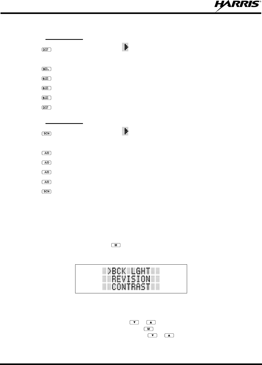
MM-013994-001, Rev. Ap1
44
8.11 MODIFY SCAN LIST
8.11.1 P7370 Model
1. Press to toggle scan OFF and verify is not displayed.
2. Select group or channel.
3. Press once to remove group or channel from list.
4. Press once to add as a normal group or channel.
5. Press twice to add as a Priority 2 group.
6. Press three times to add as a Priority 1 group.
7. Press to re-start scanning.
8.11.2 P7350 Model
1. Press to toggle scan OFF and verify is not displayed.
2. Select group or channel.
3. Press once to remove group or channel from the list.
4. Press once to add as a normal group or channel.
5. Press twice to add as a Priority 2 group.
6. Press three times to add as a Priority 1 group.
7. Press to re-start scanning.
8.12 MENU
The Menu function accesses features that are not available directly from the keypad. The order and actual
menu items available is configurable through programming. Upon radio power up, the menu item that is
at the top of the menu list will always be displayed first. Subsequent access to the menu function will
return the last menu item that was shown in the display and cursor position.
1. To enter the menu mode, then press .
2. Upon entering the menu selection mode, Menu options will appear in the display (see Figure 8-6).
Figure 8-6: Menu Display
3. The radio will continue to receive and transmit normally while in the menu function.
4. To scroll through the menu options use the or keys. When the required menu item has been
found, align the cursor with the option then press to select it. The menu item's parameter setting
shown in the display can now be changed by using or to scroll through the list of parameter
values.
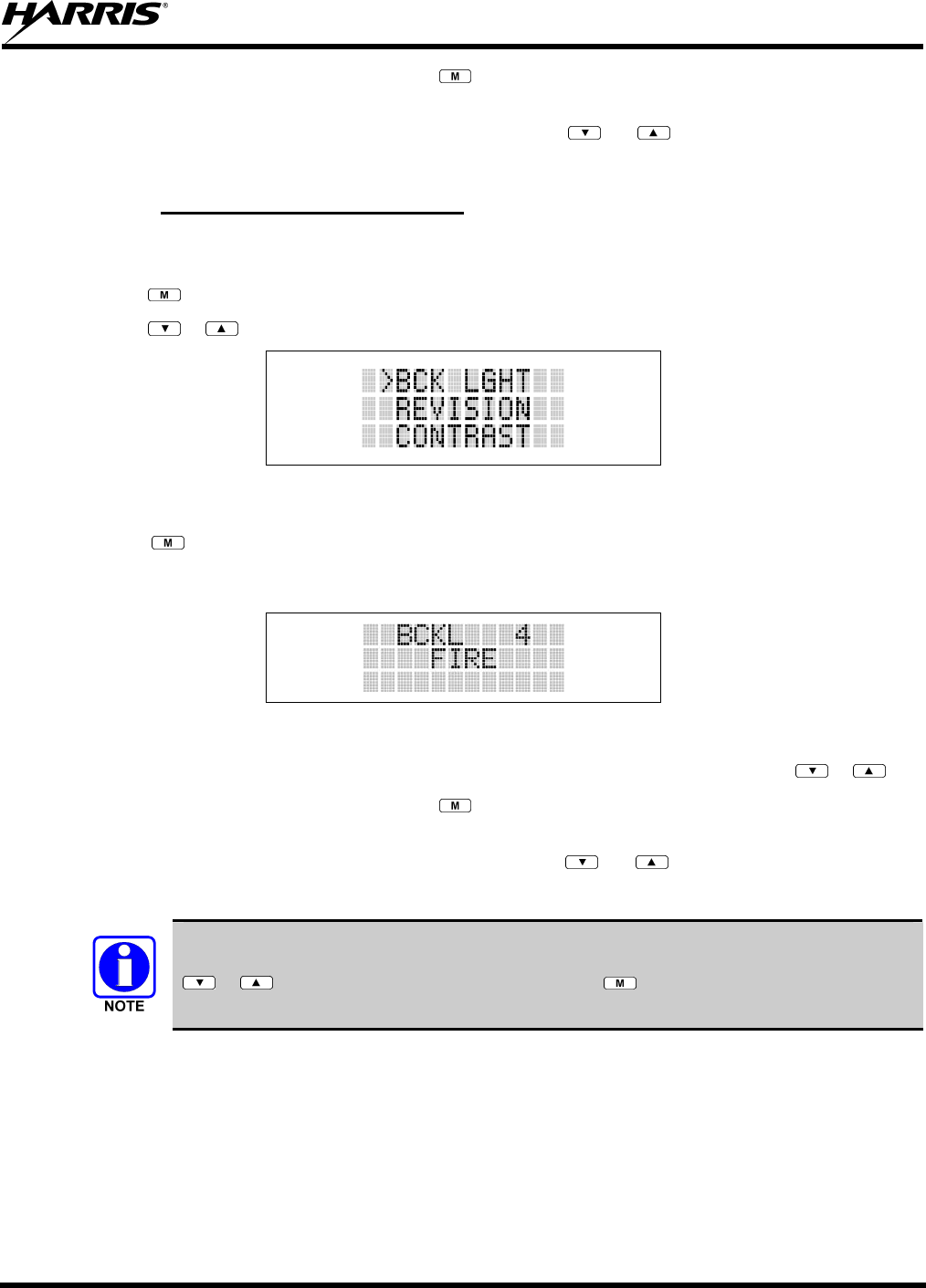
MM-013994-001, Rev. Ap1
45
5. Once the desired setting is reached press to store the value and return the menu option selection
level.
For menu items that display radio information, pressing or will scroll through a list of
informational displays. Possible menu items are listed in Table 8-5.
8.12.1 Menu Item Selection Process
An example of the backlight menu item selection process and menu item parameter change is shown in
Figure 8-7.
1. Press . The menu mode is entered.
2. Press or until the display shows:
Figure 8-7: Backlight Menu Item Selection Parameter
3. Press . The backlight menu item is activated. Line one shows the active menu item and its
current parameter setting. Line two shows the currently selected system or group name (see Figure
8-8).
Figure 8-8: Backlight Menu Display
4. The menu item's parameter setting shown in the display can now be changed by using or .
5. Once the desired setting is reached press to store the value and return the menu option selection
level.
For menu items that display radio information pressing or will scroll through a list of
informational displays. An example of information displays is shown in Table 8-5.
The TX POWER menu item, when selected, toggles LOW/HIGH power. It does not use
or to scroll nor is an additional press of the button required.
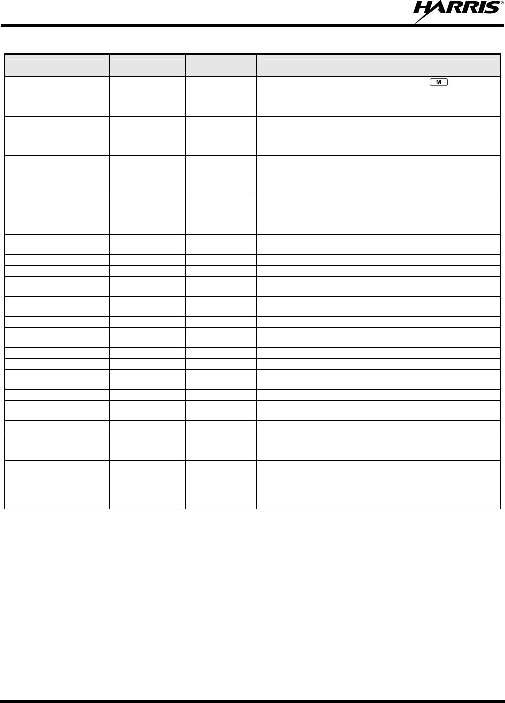
MM-013994-001, Rev. Ap1
46
Table 8-5: Menu Item Information
FEATURE DISPLAY PARAMETER
SETTING COMMENT
Keypad Lock Menu Item:
KEY LOCK
Once Selected:
LOCKED
Locked
Unlocked
Locks the keypad. To unlock; press and release then within
1 second press the option button NOTE: This sequence is also a
short cut to locking the keypad.
Backlight Adjust Menu Item:
BCK LIGHT
Once Selected:
BCKL=
OFF, 1 thru 6 Selects the light level for backlighting.
Contrast Adjust Menu Item:
CONTRAST
Once Selected:
CNTRST=
1, 2, 3, 4 Selects the display contrast level.
Transmit Power Select Menu Item:
TX POWER
Once Selected:
POWER=
HIGH or LOW Selects radio output power mode.
Radio Revision Information Menu Item:
REVISION
N/A Selects the information display to view. Informational display only
(see Table 8-6). No user selectable settings.
Toggle Scan On/Off SCAN ON/OFF Toggles Scan operation ON/OFF.
Toggle Private Mode PRIVATE ON/OFF Toggles Private Mode ON/OFF.
Display Current Encryption
Key
DISP KEY N/A Displays current encryption key. Informational display only. No
selectable settings.
Display Current Home
Group/Channel
HOME N/A Selects Home Group/Channel
Select Desired System SYS SEL N/A Selects a new system.
Add Group/Channel to Scan
List
SCAN ADD N/A Adds to Scan List.
Delete Group/Channel SCAN DEL N/A Deletes Group or Channel from Scan List.
Add/Delete Scan List SCAN A/D N/A Add or Delete from Scan List.
Select Telephone Numbers
From Phone List
PHN CALL N/A Trunked Only.
Data Operation NO DATA ON/OFF Trunked Only. Toggles Data Operation ON/OFF.
Select Individual Call from
IC List
IND CALL N/A Trunked Only.
Select Group GRP SEL N/A Trunked Only.
Feature Encryption Display Menu Item:
FEATURES
N/A Indicates current features programmed into the radio as well as
certain information required to add features to the radio.
Informational display only. No user selectable settings.
System Scan Enable Menu Item:
SYS SCAN
Once Selected:
SYSC ON or SYSC
OFF
ON/OFF Toggles System Scan feature ON/OFF.
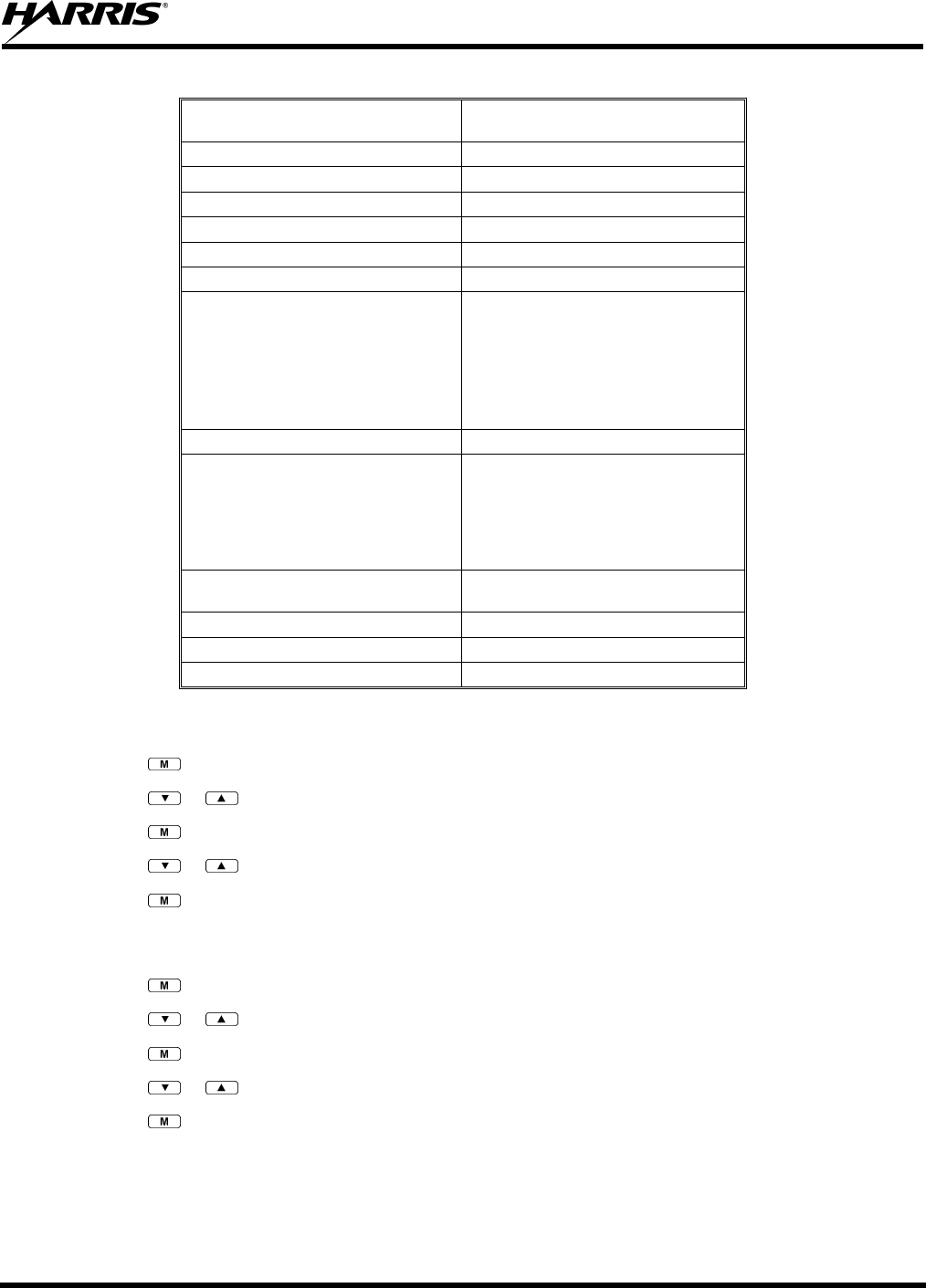
MM-013994-001, Rev. Ap1
47
Table 8-6: Information Display
RADIO ID
XXXXXXXX
LID in EDACS/EA In CONV it has no
meaning.
RAM SIZ RAM Size
FLSH SIZ Flash Size
RF BAND Frequency Band
PERS VER Software Version
DSP DATE Date DSP code was built.
DSP TIME Time DSP code was built.
DSP FEAT The DSP Features supported by the
DSP code, in Hexadecimal.
Bit mapped (see IPC spec for details):
• 0x0001 – Conventional
• 0x0002 – EDACS
• 0x0010 – AMPF
• 0x0020 – undefined
DSP VER DSP Software Version
FLSH VER FLASH Software
ex: P73U0102
P=portable, 54=5400 radio,
U=unencrypted, 01=major revision (>50
means unreleased code), 02=minor
revision
HARRIS
(C) 2009
Copyright
PERSNLTY Personality Name
BLD DATE Date host (ARM) code was built.
BLD TIME Time host (ARM) code was built.
8.13 BACKLIGHT ADJUST
1. Press to access the menu.
2. Press or to scroll through menu until “BCKLGHT” appears.
3. Press to select Backlight menu.
4. Press or to scroll through available settings OFF, 1 through 6.
5. Press to select new backlight setting.
8.14 CONTRAST ADJUST
1. Press to access the menu.
2. Press or to scroll through menu until “CONTRAST” appears.
3. Press to select Contrast menu.
4. Press or to adjust contrast setting from 1 - 4.
5. Press to select new contrast setting.
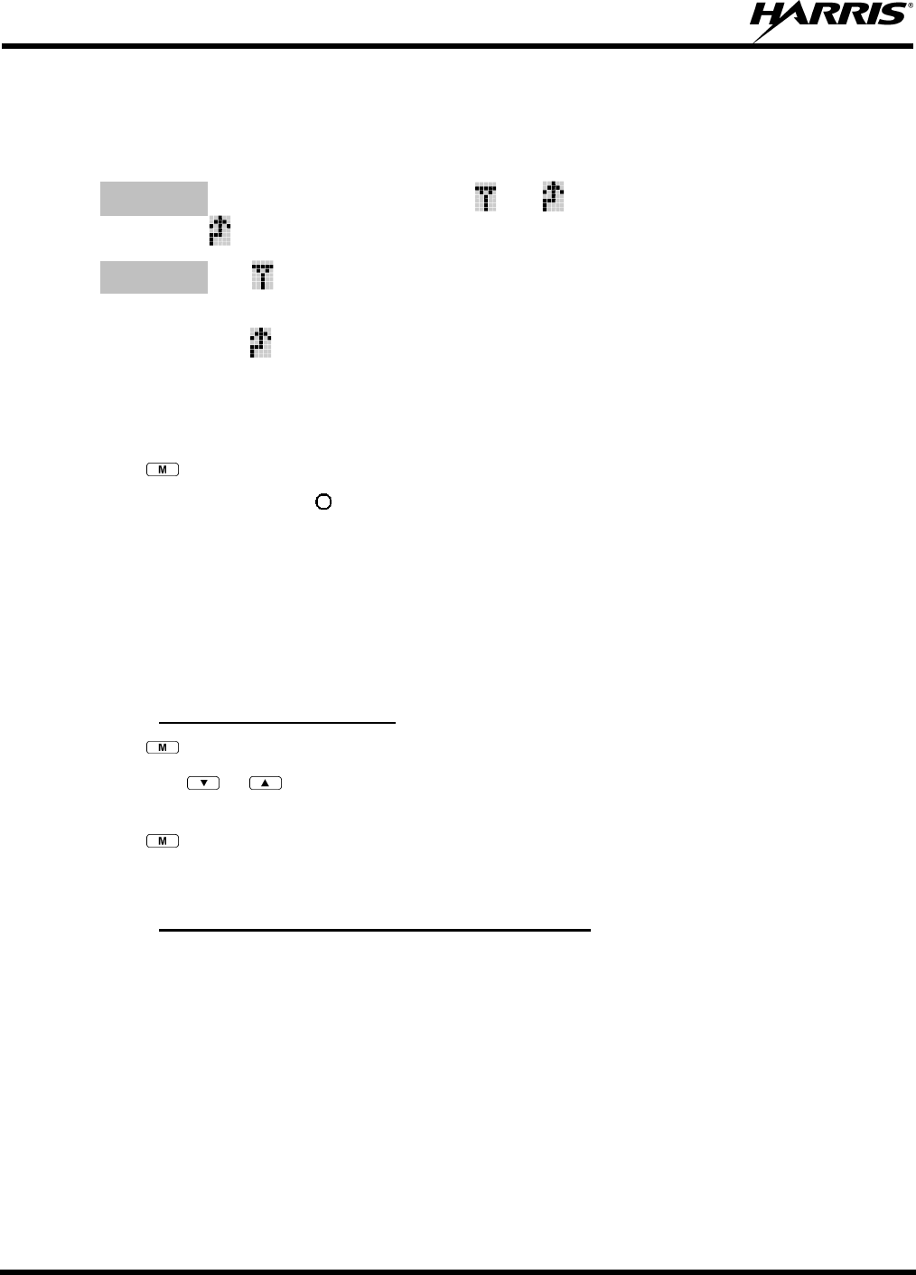
MM-013994-001, Rev. Ap1
48
8.15 DECLARING AN EMERGENCY
1. Press and hold the red Emergency/Home button (the length of time is programmable; check with the
system administrator).
2. *TXEMER* will flash in the display, plus and will be displayed. After 2-3 seconds the
transmit icon will turn off.
3. *TXEMER* and will remain until the emergency is cleared. See Section 8.21 for additional
emergency operation.
4. Press the PTT and will reappear.
5. Release PTT when the transmission is complete.
8.16 LOCKING/UNLOCKING KEYPAD
1. Press button.
2. Within 1 second, press the button on the side of the radio.
8.17 HIGH/LOW POWER ADJUSTMENT
Transmit power adjustment is possible if enabled through programming. Within conventional systems,
transmit power is adjustable on a per channel basis. Within EDACS trunking systems, transmit power is
adjustable on a per system basis.
There are two ways to toggle between high and low power, described in Sections 8.17.1 and 8.17.2.
8.17.1 Using the Menu Button
1. Press .
2. Using the or keys, scroll until the cursor (>) appears to the left of “TX POWER” in the
display.
3. Press again to toggle between High and Low power.
4. “POWER = HIGH” or “POWER = LOW” will appear momentarily on the top line of the display.
8.17.2 Using the Pre-Programmed Option Button
Press the Option button. “POWER = HIGH” or “POWER = LOW” will appear momentarily on the top
line of the display.
8.18 DIGITAL VOICE OPERATION
Digital voice programmed systems have three (3) different voice modes: clear (analog), digital, and
private (encrypted). The voice modes are programmed on a per-group basis within each trunked system
and on a per-channel basis within each conventional system.

MM-013994-001, Rev. Ap1
49
8.18.1 Clear Mode
The Clear Mode is a voice mode in which the radio transmits and receives only clear (analog) voice
signals. These analog signals are non-digitized and non-encrypted. Clear mode transmissions can be
monitored easily by unauthorized persons.
Groups or channels programmed for clear operation cannot transmit or receive digital or
private messages.
8.18.2 Digital Mode
The Digital Mode allows the radio to transmit and receive digitized voice signals. Digital signals provide
improved weak signal performance and cannot be easily monitored with a standard receiver. Groups or
channels programmed for digital operation transmit only digital signals. Message trunked group calls and
individual phone calls (I-Calls) are answered back in the mode in which they were received assuming the
call or hang time is still active. Individual phone, all call, and emergency calls are transmitted clear if the
digital mode is disabled or inoperative.
1. If receiving an analog message trunked call, the radio responds in the analog mode during the
hang time on the working channel.
2. If receiving an analog I-Call, the radio responds in the analog mode during the hang time.
3. When using the *WHC* feature to respond to an I-Call (after the hang time has expired), the call
is transmitted in the mode defined by the system mode as programmed for the current system if
the ID being called is not in the I-Call list. If the ID is in the I-Call list, then the call is transmitted
as defined by the I-Call mode programmed in the list for that ID.
The overdial DTMF tones are not available while in the Digital Mode.
8.18.3 Private Mode
The Private Mode allows the radio to transmit encrypted messages and receive clear or private
transmissions. The radio transmits private if the group/channel is programmed for private operation and
forced operation is pre-programmed. If auto-select operation is pre-programmed and the radio is in the
Private Mode, the radio transmits in the mode of the received call if the hang time is active. If no hang
time is active, the radio transmits private.
Cryptographic keys are transferred to the radio using a cryptographic Keyloader. Up to seven (7)
different cryptographic keys, numbered 1-7, can be transferred from a Keyloader and stored in the radio.
An individual key is automatically selected on a per-group/channel basis according to the radio
programming. Groups and channels within the digital system can be programmed for keys 1-7 (private).
Up to 8 banks of 7 keys can be stored for private systems. The bank is specified per system.
When operating on a group or channel programmed for Private Mode, all transmissions are private
transmissions and the radio receives clear and private signals. The status icon is displayed when the
Private Mode is enabled. If the selected group or channel is programmed for auto-select capability, the
mode may be toggled between private and clear with the key, then following the selection mode
rules. Radios programmed for forced private operation do not allow a change of the transmit mode.
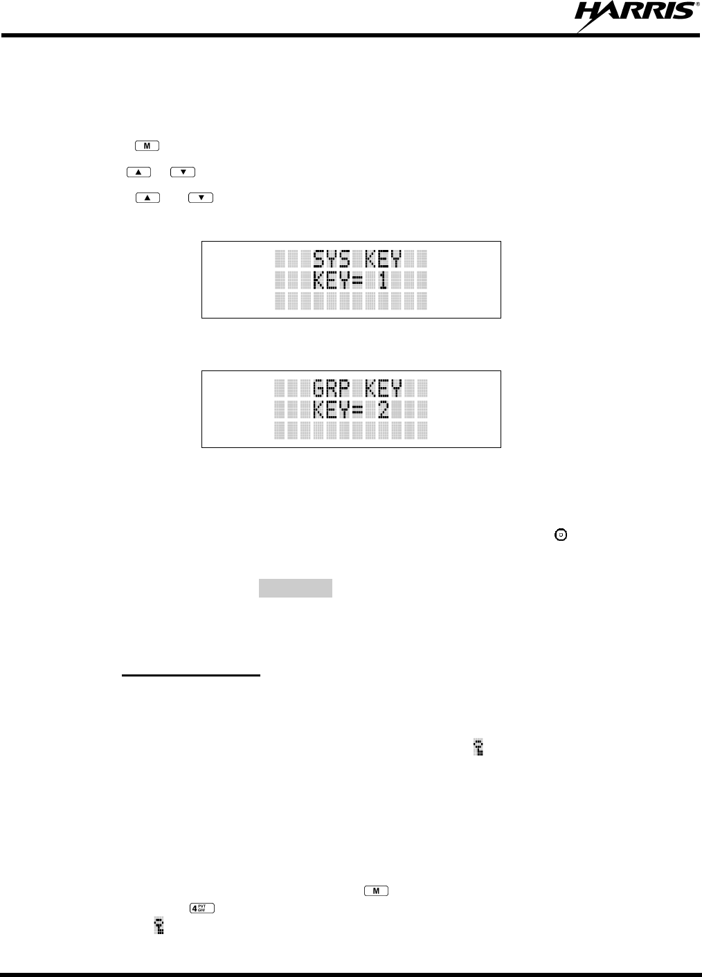
MM-013994-001, Rev. Ap1
50
8.18.3.1 Displaying the Currently Used Cryptographic Key Number
To display the Currently Used Cryptographic Key Number for either the system encryption key (for
special call such as individual, phone, all, agency or fleet) or the group/channel key (for group or
conventional calls), perform the following procedure:
1. Press the button.
2. Use the or button to select "DISP KEY."
3. Use the or button to toggle between displaying the system key (Figure 8-9) or the
group/channel key (Figure 8-10).
Figure 8-9: System Encryption Key Display
Figure 8-10: Group/Channel Encryption Key Display
8.18.3.2 Key Zero
All cryptographic keys can be zeroed (erased from radio memory) by pressing the button and while still
pressing this button, press and hold the OPTION button. Press both buttons for 2 seconds. A series of
beeps will begin at the start of the 2 second period and then switch to a solid tone after the keys have been
zeroed. The display will indicate KEY ZERO.
If the cryptographic key(s) are zeroed, one or more keys must be transferred from the Keyloader into the
radio before private communications may continue.
8.18.4 Private Operation
8.18.4.1 Receiving an Encrypted Call
When receiving, the radio automatically switches between clear or private operation. If the transmission
being received is an encrypted transmission, it will be decrypted, the icon will be displayed, the receiver
will unsquelch, and the message will be heard in the speaker. For this to occur, the selected group or
channel must be programmed for private operation and the correct cryptographic key must be loaded into
the radio.
8.18.4.2 Transmitting an Encrypted Call
1. Select the desired group or channel.
2. Place the radio in Private Mode by pressing key; then follow the selection mode rules. On a
System radio, the key can be used to toggle the Private Mode ON/OFF. When Private Mode is
enabled, the icon is displayed.
MM-013994-001, Rev. Ap1
51
3. If the last state of the radio was Private Mode, the Private Mode will be enabled on power up. Also,
the Private Mode will be enabled if forced operation has been programmed in the radio.
If a group or channel is not programmed for Private Mode operation, PVT DIS will be displayed if
an attempt is made to enable private transmit mode. It is not possible to operate on this group/channel
in Private Mode.
If the radio does not have the correct encryption key loaded, NO KEY# will be displayed and the call
will not be transmitted.
4. Continue with standard transmission procedures. A Private Mode access tone will be heard when the
PTT button is pressed.
8.18.4.3 Scanned Group Calls
Receiving a Scanned Group Call is the same as receiving a selected group call. During the scan hang
time, if the radio was programmed for auto-select, it will transmit back in the same mode it received the
call. For example, if a clear group is entered in the scan list, it will only receive clear calls. If the same
group was available in private and entered in the scan list, it can receive clear and private calls, provided
auto-select was programmed in the radio. The user can select transmitting on the scanned or selected
group. If a group is entered in the scan list more than once and under different modes, (clear, digital, or
private), then only the first occurrence of the group will be used.
Table 8-7: Transmit/Receive Mode Compatibility for Digital Voice Operation
GROUP/CHANNEL
PROGRAMMING
(TRANSMIT)
CLEAR
RECEIVE DIGITAL
RECEIVE PRIVATE
RECEIVE
CLEAR Yes No No
DIGITAL Yes Yes No
PRIVATE Yes No Yes*
*assumes the proper cryptographic key is loaded
Conventional digital or encrypted channels require Channel Guard on the channel to
operate correctly.
The voice coding technology embodied in this product is protected by intellectual
property rights including patent rights, copyrights, and trade secrets of Digital Voice
Systems, Inc. The user of this technology is explicitly prohibited from attempting to de-
compile, reverse engineer, or to disassemble the Object Code, or in any other way
convert the Object Code into a human-readable form.
8.19 SCANNING TRUNKED GROUPS
Groups that have been previously added to the scan list on a per system basis may be scanned. Each
system's group scan list is retained in memory when the radio is powered OFF or when the battery pack is
removed.
MM-013994-001, Rev. Ap1
52
8.19.1 Turning Scan On and Off
1. Toggle Scan operation ON by pressing (P7350 model) or (P7370 model). icon rotates
clockwise to indicate radio is scanning.
2. Toggle Scan operation OFF by again pressing (P7350 model) or (P7370 model). will
disappear.
• If the radio scans to a group other than the selected group then receives a call on the selected
group, the radio will switch to the selected group. However, if the “scanned-to” group is
programmed at a higher priority the radio will remain on the “scanned-to” group.
• The radio will continue scanning if a new group is selected when scan is ON.
3. Pressing the PTT button when scan is ON will cause the radio to transmit on the displayed group or to
the currently selected group (depending on programming).
8.19.2 Adding Groups to a Scan List
P7350 Model Radio
1. Scan must be OFF to add/delete groups to/from the scan list. If the Scan icon is ON, press the
key to turn Scan OFF.
2. Select the desired group using the System/Group/Channel control knob and/or the or keys. If
the selected group is currently on the list, pressing will display on line three.
3. If the scan list status icon is blank ( ), the group can be added to the scan list by pressing the key.
will be displayed on line three.
4. Press the key a second time to set the group to Priority 2. A is displayed on line three.
5. Press a third time to set the group to Priority 1. A is displayed on line three. The priority level
section sequence only advances the group to the next high priority level and stops at priority level 1.
To select a lower priority level, the group must be deleted from the scan list and then added back to
the scan list. Each new group added to the scan list starts at the lowest priority. If the Priority 1 and
Priority 2 groups are already set and a new group is assigned as Priority 1 or Priority 2, the previously
assigned group will change to non-priority scanning. One of the following messages may be
momentarily displayed.
SCAN DIS The radio is not programmed to scan.
FIXED P1 A Priority 1 group has been pre-programmed into the radio. A new Priority 1 group
cannot be selected.
FIXD LST A fixed scan list has been pre-programmed into the radio. It is not possible to change
the list without reprogramming the radio.
To quickly view multiple group scan status, press then slowly but consistently rotate
the group knob. Each group status will appear on the display.
MM-013994-001, Rev. Ap1
53
P7370 Model Radio
1. With scan operation turned OFF, select the desired group to add to the selected trunked system group
scan list.
2. Press . The current priority status of the group will be displayed in column 10 of line three for a
time-out period. If the group is not part of the scan list, the status will be blank.
3. While the status is displayed, press to add the group to the scan list. is displayed on line three.
4. Press a second time to set the group to Priority 2. A is displayed on line three.
5. Press a third time to set the group to Priority 1. A is displayed on line three. The priority level
selection sequence only advances the group to next higher priority level and stops at priority level 1.
To select a lower priority level, the group must be deleted from the scan list and then added back to
the scan list. Each new group added to the scan list starts at the lowest priority. If the Priority 1 and
Priority 2 groups are already set and a new group is assigned as Priority 1 or Priority 2, the previously
assigned group will change to non-priority scanning. One of the following messages may be
momentarily displayed.
SCAN DIS The radio is not programmed to scan.
FIXED P1 A Priority 1 group has been pre-programmed into the radio. A new Priority 1 group
cannot be selected.
FIXD LST A fixed scan list has been pre-programmed into the radio. It is not possible to change
the list without reprogramming the radio.
To quickly view multiple group scan status, press either or the key. Then slowly
but consistently rotate the group knob. Each group status will appear on the display.
8.19.3 Deleting Groups from a Scan List
P7350 Model Radio
1. With scan operation turned OFF, select the desired group to delete from the selected trunked system
group scan list.
2. Press . The current status of the group is displayed for a time-out period.
3. While the current status is displayed, press . until the group from the scan list is "blank." The
sequence is "blank," , , , "blank." Any group that is not in a trunked system group scan list will
show a "blank" for the time-out period when it is the selected channel.
P7370 Model Radio
1. With scan operation turned OFF, select the desired group to delete from the selected trunked system's
group scan list.
2. Press . The current status of the group is displayed for a time-out period.
3. While the status is displayed, press to delete the group from the scan list. , ,or turns OFF.
Any group that is not in a trunked system group scan list will show a "blank" for the time out period
when it is the selected channel.
MM-013994-001, Rev. Ap1
54
8.19.4 Nuisance Delete
A group can also be deleted from the scan list, if it is not the currently selected group, by pressing the
key (P7350 model) or the key (P7370 model) during scan operation while the radio is displaying the
unwanted group. The group will be deleted from the system's group scan list in the same manner as if
done using the steps above. Deletions done in this manner will not remain deleted if the radio is powered
OFF and then powered ON.
8.20 SCANNING TRUNKED SYSTEMS
The radio can be programmed using Radio Personality Manager (RPM) with the following System Scan
features. Then these features are automatically enabled when the radio is powered ON. A key or menu
option is also defined to allow the System Scan features to be toggled during radio operation. The System
Scan state will be maintained through system changes but will default to ON when the radio is powered
ON.
Enable/Disable via Menu Selection
Press and then use the or buttons to scroll through the selections until SYS SCAN is
displayed. Then press to toggle the System Scan state. The SYSC ON or SYSC OFF display
message is displayed for two seconds to show the new state.
Enable/Disable via Pre-Programmed Keypad Key
Press the key pre-programmed to toggle System Scan and the SYSC ON or SYSC OFF display message
is displayed for two seconds to show the new state.
8.20.1 Wide Area System Scanning
The P7300 series radio can be pre-programmed through RPM for Wide Area System Scan operation for
roaming across mobile systems. EDACS radio systems manage the radios assigned to the system via a
control channel (CC). Upon the loss of the currently selected system's control channel, radios can be
programmed to automatically scan the control channels of other systems. If a new control channel is
found, the radio will switch to the new system and sound an alert tone.
8.20.2 Priority System Scan
The radio can also be pre-programmed for Priority System Scan. The priority system is the desired or
preferred system. While receiving the control channel of the selected system, the radio will periodically
leave the selected system and search for the control channel of the priority system. This is done at a pre-
programmed rate defined by the value in the Priority Scan Time control, unless the ProScan™ algorithm is
enabled, as explained in the following sections. This priority scan timer is reset each time the PTT button
is pressed or when the call is received. If the priority system control channel is found, or meets the
predefined criteria (ProScan), the radio will automatically switch to the priority system.
8.20.2.1 Enabling the Wide Area System Scan Function
If the radio cannot find the control channel of the selected system and begins to wide area system scan,
the radio will only scan for the priority system control channel if the priority system is in the wide area
scan list.

MM-013994-001, Rev. Ap1
55
8.20.2.2 When ProScan is Enabled
The radio monitors the priority system and will switch to the priority system if the pre-preogrammed
criteria ProScan options are met. If ProScan is enabled, the rate at which the radio will scan for the
priority system is defined by the System Sample Time control, set in RPM, (refer to RPM On-Line Help).
See Section 8.20.3 for more information on ProScan.
8.20.3 ProScan
The radio may be programmed for ProScan system scan operation for multi-site applications. ProScan is
a multi-site system scanning algorithm. ProScan provides the radio with the ability to select a new
system for the radio to communicate on, when the selected system drops below a predefined level. This
algorithm enables each radio to analyze the signal quality of its current control channel and compare it
with the signal quality of the control channel for each site in its adjacent scan list. The signal quality
metric used for the ProScan algorithm is based on a combination of both Received Signal Strength
Indicator (RSSI) and Control Channel Verification (CCV) measurements. When the selected system
degrades to a pre-programmed level, the radio will begin to look for a better control channel. Once a
control channel that exceeds the pre-programmed parameters is found, the radio will change to the new
system and emit a tone (if enabled through programming). If the control channel is completely lost, the
radio will enter Wide Area System scanning and search the programmed adjacent systems until a suitable
control channel is found.
8.21 EMERGENCY OPERATION
The radio's ability to declare an emergency, clear an emergency, remain locked on an emergency system
and group, and the emergency audio and display freeze can each be enabled or disabled through
programming. When an emergency is declared scanning will stop and restarts only after the emergency
has been cleared.
8.21.1 Receiving an Emergency Call
When receiving an Emergency Call on the selected group and system, an alert beep is heard and is
displayed. The message *RXEMER* flashes in the display on line two until the emergency condition is
cleared.
8.21.2 Declaring an Emergency Call
Perform the following steps to send an emergency call to a selected system and group (or on an optionally
pre-programmed group).
1. Press and hold the red EMERGENCY button that is on top of the radio in front of the antenna for
approximately one second (this time is programmable and therefore could be longer or shorter; check
with the system administrator). The radio will transmit an emergency call request with the radio ID
until an emergency channel assignment is received.
2. When the working channel assignment is received, the radio sounds a single beep indicating the radio
has auto keyed (see Table 8-4) and is ready for voice transmission. *TXEMER* flashes on line two in
the display until the emergency is cleared.
3. Press PTT and speak into the microphone in a normal voice. and momentarily turn ON.
4. Release PTT when the transmission is complete.
To clear the emergency, first press and hold the button. While continuing to hold the button, press
the EMERGENCY button. (This will work if the radio is programmed to clear emergencies.)
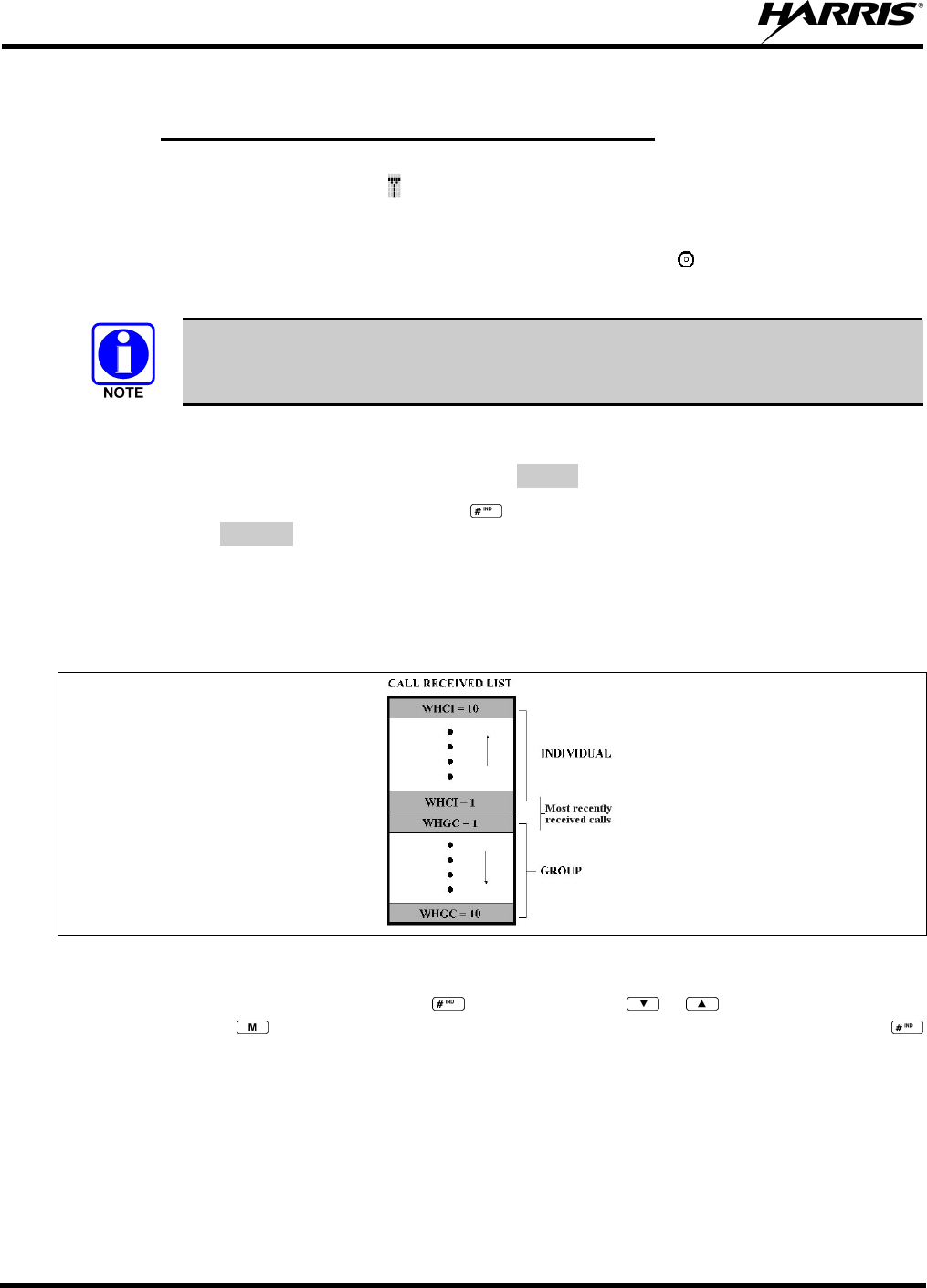
MM-013994-001, Rev. Ap1
56
8.22 INDIVIDUAL CALLS
8.22.1 Receiving and Responding to an Individual Call
When the radio receives an individual call (a call directed only to the user's radio), it un-mutes on the
assigned working channel and displays . The first line on the display shows the logical ID number of the
unit sending the message, or the associated name if the ID number is found in the individual call list. The
radio can be programmed to ring when an individual call is received. If enabled, the ring begins five
seconds after the caller un-keys and will continue until the PTT button, the button or the individual call
mode is entered.
The volume of the ring is adjustable through the volume control levels.
If a response is made by pressing the PTT to the call prior to the programmed call-back time-out, the call
will automatically be directed to the originating unit. If a response is not made before the call-back time-
out, the radio will return to normal receive display, and *WHC* will appear on the first line of the LCD.
To respond after the call-back time-out, press the key. The radio's display will show the callers ID on
the first line and WHCI=1 on the second line. Pressing the PTT button at this point will initiate an
individual call back to the original caller.
The radio stores the IDs of the last 10 callers in the Calls Received List as shown. Individual calls are
stored in the top half of the list (1-10) and Group calls are stored in the bottom half of the list (1-10). The
most recent call is stored in position 1, the second most recent call is stored in position 2, etc.
Figure 8-11: Calls Received Lists
To access the Calls Received List, press the key twice. Use the or buttons to scroll through
the list. Pressing the key will display the time elapsed since the call was received. After pressing
the display will appear similar to Figure 8-12.
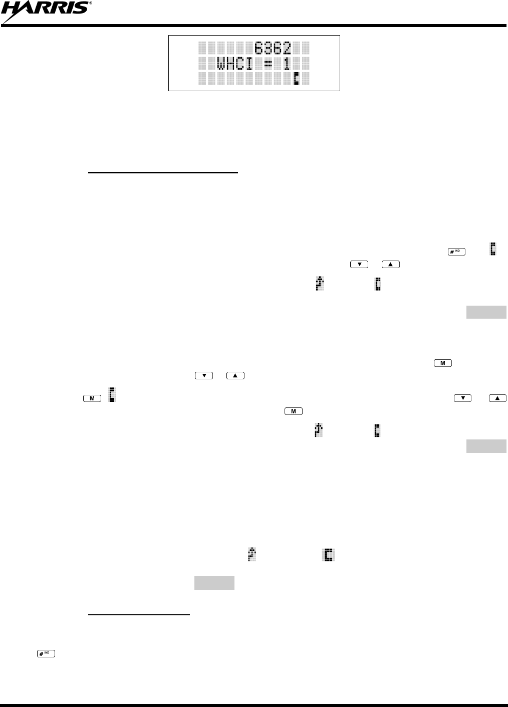
MM-013994-001, Rev. Ap1
57
Figure 8-12: WHC Individual Call Display
Pressing the PTT will initiate an individual call to the displayed logical ID. Powering the radio OFF and
ON will clear this list.
8.22.2 Sending an Individual Call
8.22.2.1 Pre-Stored Individual Calls
The following procedures describe how to initiate and complete a Pre-Stored Individual Call.
P7370 Model Radio
1. To select a pre-stored individual phone number, enter the individual call mode using the key. is
displayed. Then scroll through the list of stored numbers using the or keys.
2. Press the PTT button; when the radio is clear to transmit, turns ON, turns OFF, and the channel
access tone sounds. Line one shows the called individual's name if found in the list of stored
individuals or LID followed by the logical ID number of the unit being called. The message *INDV*
displays on line two.
P7350 Model Radio
1. To select a pre-stored individual number, enter the menu mode by pressing the key. Scroll
through the mode list using the or buttons.
2. Press . is displayed. Scroll through the list of stored phone numbers using the or
buttons until the desired number is displayed. Press .
3. Press the PTT button; when the radio is clear to transmit turns ON, turns OFF, and the channel
access tone sounds. Line one shows the called individual's name or LID. The message *INDV*
displays on line two.
8.22.2.2 Direct Dial Individual Calls (P7370 Model Only)
1. The following procedure describes how to initiate and complete a Direct Dial Individual Call.
2. The individual call ID is not stored in the pre-stored list of call IDs but the individual unit ID is
known, it can be entered directly from the keypad.
3. Press and hold the PTT button to transmit. will turn ON, will turn OFF, and the channel access
tone will sound. Line one shows the called individual's ID followed by the logical ID number of the
unit being called. The message *INDV* displays on line two. Proceed talking into the microphone.
8.22.3 Call Storage Lists
There are two lists available for call storage in the P7300 series radios, the calls received list (1 - 10) and
the personality list (1 - 99 as defined by the user). When the individual call mode is entered by pressing
, the calls received list is available. The user can toggle to the personality list by selecting any index
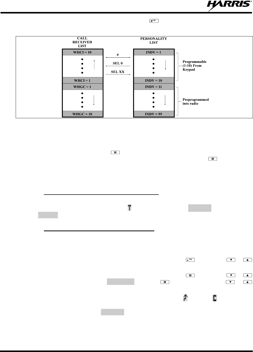
MM-013994-001, Rev. Ap1
58
other than 0 or toggle between the two lists by pressing the key. If wrap is enabled, the calls received
list wraps on itself and not into the other list.
Figure 8-13: Calls Received and Personality Lists
The saved call list shows all ten storage locations. If no calls have been received, the saved call list will be
empty and the pre-stored list will be available upon entering the individual call mode.
When in the saved call list, pressing the key toggles the time stamp ON and OFF. The time stamp
indicates how long ago the call was received. When in the pre-stored list pressing the key toggles the
Logical IDentification (LID) ON and OFF.
8.23 TELEPHONE INTERCONNECT CALLS
8.23.1 Receiving a Telephone Interconnect Call
When the radio receives a telephone interconnect call (a call directed only to the user's radio), it un-mutes
on the assigned working channel and displays . The first line displays *PHONE*. The second line
displays *INDV*. Proceed with the call. Press the PTT to talk, release the PTT to listen.
8.23.2 Sending a Telephone Interconnect Call
8.23.2.1 Pre-Stored Number
Use the following procedures to initiate and complete a Telephone Interconnect call.
1. P7370 Model: To select a previously stored phone number, press the key. Use the or
buttons to scroll through the list of stored numbers.
P7350 Model: To select a previously stored phone number, press the key. Use the or
buttons to select the menu option PHN CALL. Press the key again then use the or
buttons to scroll through the list of pre-stored numbers.
2. Press and release the PTT button. When the radio is clear to transmit, turns ON, turns OFF, and
the channel access tone sounds. Line one shows the accompanying name selected from the list of
stored numbers. The message *PHONE* appears on line two of the display. The radio then
automatically transmits the programmed number stored in the special call queue.
3. A telephone ring will be heard from the speaker. When someone answers the phone, press the PTT
button and speak into the microphone. Release the PTT button to listen to the callee. Unsuccessful
MM-013994-001, Rev. Ap1
59
interconnect signaling returns the radio to the normal receive mode and the number remains displayed
until the special call is cleared or the time-out expires or another group or system is selected.
Terminate a call by pressing the button.
In half-duplex mode, only one person may talk at a time. The radio PTT button needs
to be pressed in order to communicate to the individual called and released for the
individual called to be heard.
8.23.2.2 Direct Dialing of Phone Calls (P7370 Model Only)
1. If the phone number is not stored in the pre-stored list of phone numbers, but the phone number is
known, it can be entered directly from the keypad. Start by pressing the key, then enter the
required number from the keypad. Press and release the PTT button.
The last number directly entered can be recalled by first pressing then pressing the
PTT button.
2. A telephone ring can be heard from the speaker. When someone answers the phone, press and hold
the PTT button and speak into the microphone. Release the PTT button to listen to the individual
called. Unsuccessful interconnect signaling returns the radio to the normal receive mode and the
number remains displayed until the special call is cleared or the time-out expires or another group or
system is selected.
3. To terminate the call, momentarily press the button.
8.23.3 Dual-Tone Multi-Frequency: Overdial/Conventional Mode
Once the radio has established a connection to the public telephone system, it may be necessary to “over-
dial” more digits to access banking services, answering machines, credit card calls, or other types of
systems that require Dual-Tone Multi-Frequency (DTMF) access digits.
Overdial operation can also be used to initiate a telephone interconnect call via DTMF signaling if a dial
tone has already been accessed on the system. This method makes a telephone interconnect call while
operating in the conventional mode but will also function in trunked mode if a dial tone is directly
accessible.
Telephone numbers and other number sequences for overdialing can be stored in the phone list when
programming the radio. These numbers are accessed by pressing the key, then following the selection
mode rules. Perform the following procedures to access and dial these stored numbers.
P7350 Model Radio
1. Follow the procedure in Section 8.23.2 to establish a connection to the telephone system or consult
the system administrator for the procedure to access a dial tone on the trunked or conventional
system.
2. Enter selection mode first to enable entry of Overdial numbers by pressing the button.
3. Follow the selection mode rules to call up a stored number from the phone list: Use the or
buttons to scroll through the list of stored numbers. is displayed. Press the PTT to send the overdial
sequence once. If the number needs to be transmitted again it must be selected or entered again (this
prevents unwanted numbers from being sent the next time the PTT button is pressed during the call).

MM-013994-001, Rev. Ap1
60
Overdial select/entry mode remains active until the call is dropped, cleared, or is pressed. The
overdial select/entry mode can be re-entered if the call is still active by pressing .
P7370 Model Radio
1. Follow the procedure in Section 8.23.2 to establish a connection to the telephone system or consult
the system administrator for the procedure to access a dial tone on the trunked or conventional
system.
2. Overdial numbers are transmitted using one of the following methods:
METHOD 1: 1. Enter the overdial selection mode by pressing the button.
2. Use the or buttons to scroll through the list of stored numbers. is
displayed. Press the PTT to send the overdial sequence once. If the numbe
r
needs to be transmitted again it must be selected or entered again (this
prevents unwanted numbers from being sent the next time the PTT button
is pressed during the call).
Overdial select/entry mode remains active until the call is dropped, cleared, o
r
is pressed. The overdial select/entry mode can be re-entered if the call is
still active by pressing .
METHOD 2: (P7370 model radios only)
1. Enter the overdial selection mode by pressing the button.
2. Press and hold the PTT button while entering the overdial numbe
r
sequence from the keypad. This method sends DTMF tones during
individual, telephone interconnect, trunked group, or conventional channel
calls. Press the PTT to send the overdial sequence once. If the numbe
r
needs to be transmitted again it must be selected or entered again (this
prevents unwanted numbers from being sent the next time the PTT button
is pressed during the call). Note: Anytime the PTT button is pressed an
d
held, the keypad is enabled for DTMF entry.
Overdial select/entry mode remains active until the call is dropped, cleared, o
r
is pressed. The overdial select/entry mode can be re-entered if the call is
still active by pressing .
This overdial select/entry mode remains active until dropped, cleared, or is pressed. The overdial
select/entry mode can be re-entered if the call is still active by pressing the button.
8.24 PROGRAMMABLE ENTRIES
8.24.1 Pre-Storing Individual and Telephone Interconnect Calls from the
Keypad
Individual Call ID numbers, telephone numbers, and other number sequences for overdialing are stored in
the special calls lists when programming the radio. The first ten entry locations of these lists can be
changed by the radio operator. The keypad is used when adding, changing, and storing numbers in these
entry locations.
Use the following procedure to store a number in one of the first ten entries of a special call list:
1. Press the or button to enter the individual call list or the phone call list. is displayed.
2. Scroll through the list using the or keys until one of the first ten entries is reached. NO
ENTRY is displayed if the location is empty.
MM-013994-001, Rev. Ap1
61
3. Enter the desired number. If necessary, a pause can be entered by pressing and holding 0-9, , or
until an underscore appears in the display (telephone interconnect only). The individual call list
entries will accept up to 5 digits. The phone call list entries accept a combination of up to 31 digits
and pauses.
4. Press and hold the key until the display changes indicating that the number has been stored.
Repeat steps 1-4 to store additional numbers, to change numbers already stored, or to change the storage
location of a number.
8.25 STATUS/MESSAGE OPERATION
The Status and Message operations allow for the transmission of a pre-programmed status or a pre-
programmed message to an EDACS site. Each Status and Message is assigned an ID then cross-
referenced with the representative status condition (“Off Duty,” for example) or a message (“Call home”).
In addition, Status conditions can also be associated with a programmable Menu entry (required for
second method of transmitting a Status condition (see Section 8.25.1).
8.25.1 Status Operation
P7370 Model Radio
One of two methods can be used to transmit a status condition.
METHOD 1: 1. Press the key, then use the or buttons to scroll to the pre-programmed
status condition. STATUS and 0 through 9 pre-programmed status selections are
available from the menu.
2. If STATUS is selected, you need to enter the number of the status condition you
intend to transmit. If no status has been programmed for the selected number key,
the radio will display NO ENTRY. A valid selection will display the status for a pre-
programmed time.
After the time-out expires or the key has been pressed (the key will override the
time-out period), the status is selected and will be transmitted to the site or stored in the
radio memory where it can be polled by the site at a future time.
METHOD 2: 1. Press the key.
2. Press the corresponding pre-programmed 0 through 9 status condition key. If no
status has been programmed for the selected number key, the radio will display
NO ENTRY. A valid selection will permit the status condition to appear in the top
line of the display and the status ID to appear in the second line of the display for a
pre-programmed time.
After the time-out expires or the key has been pressed (the key will override the
time-out period), the status is selected and will be transmitted to the site or stored in the
radio memory where it can be polled by the site at a future time.
View the currently selected status after it has been transmitted by pressing the key and then the
key and then the button prior to the time-out period. If the status was not sent successfully to the site,
the text associated with the status condition will flash in the display.
The status selection can be changed by pressing a different status key 0 through 9, or the status operation
can be cancelled by pressing Option Button 2 . Both operations must be carried out prior to the time-
out period.

MM-013994-001, Rev. Ap1
62
8.25.2 Message Operation
The following method can be used to transmit a Message using the Message Operation.
1. Press the key.
2. Press the corresponding pre-programmed 0 through 9 pre-programmed “message” key. If no message
has been programmed for the selected number key, the radio will display NO ENTRY. A valid
selection will permit the message to appear in the top line of the display and the message ID to appear
in the second line of the display for a pre-programmed time.
The message selection can be changed by pressing a different message key 0 through 9, or the message
operation can be cancelled by pressing Option Button 2 . Both operations must be carried out prior to
the pre-programmed time-out period.
8.26 DYNAMIC REGROUP OPERATION
Dynamic Regroup Operation permits multiple talk groups (up to eight) to be added to a radio via the
system manager. The radio must be pre-programmed to respond to regrouping. Dynamic regrouping will
not be activated in a radio until the system manager sends an activation message. Each radio that receives
and acknowledges the regrouping instructions is successfully regrouped.
Pressing and holding the button for 2.5 seconds toggles the user into and out of the dynamic regroup
groupset. A double beep will sound for entry or exit. The display will indicate REGRP_0x where "x" is a
digit of 1 to 8 indicating the group (when dynamic regroup has been enabled by the user). If the radio is in
dynamic regroup and the user selects a group that has not been regrouped, the display will show NO
ENTRY. The radio will be prevented from transmitting and receiving calls in this condition except for
scanned groups.
After the time-out expires or the key has been pressed (the key will override the time-out
period), the status is selected and will be transmitted to the site or stored in the radio memory where it can
be polled by the site at a future time.
8.26.1 Emergency Operation
If the pre-programmed groupset on the currently selected system contains an EMER/HOME group and
the radio is in dynamic regroup, the radio will declare the emergency on the currently selected dynamic
group.
8.27 MACRO KEY OPERATION
Macro key operation permits the user to accomplish a series of keystrokes with a single "macro"
keystroke. Each Macro Key is capable of executing up to twenty (20) keystrokes, to any push button input
(i.e., keypad keys, OPTION buttons, etc.). Each macro key can be pre-programmed to activate when
pressed or when released.
A macro key may also be pre-programmed to change the key stroke sequence the next time the macro key
is activated.
For detailed operation and assignment of macro keys, contact your communications supervisor or
administrator.
8.28 PORTABLE DATA
The P7300 series portable radios, when operating in the EDACS Trunked configuration, permit both
voice and data calls to be transmitted and received. The radio can handle only one type of call at a time;

MM-013994-001, Rev. Ap1
63
however, either data or voice is selected transparently by the operator through normal usage of the radio.
Data communications is not supported in conventional mode.
The radios can be connected to a Mobile Data Terminal (MDT) or to a host computer. Any RS-232
compatible device that supports the Radio Data Interface (RDI) protocol (Version 1.91 or greater) may be
connected to the radio. Support for MDTs or host computers is a programmable option per radio.
Additionally, radios may also be programmed for data only operation (no voice calls transmitted or
received).
8.28.1 Displays
The following will be displayed during the various states of data mode of operation:
TX DATA Appears on top line of display when the radio is transmitting a data call.
RX DATA Appears on top line of display when the radio is receiving a data call.
DATA OFF Appears on top line of display when the radio is in the data disabled state.
DATA ON Appears for two seconds on top line of display when the radio is toggled to the data
enabled state.
8.28.2 DATA OFF Operation
The radio can be placed in the data disabled state by any of the following methods. When the data state is
disabled, DATA OFF appears on the top line of the display.
• Declaring an emergency (not to be used unless an actual emergency condition exists). Alert tone will
sound.
• Pressing Option Button 1 (if pre-programmed as “no data” key). Alert tone will sound.
• Pressing the pre-programmed “no data” (ND) key. Refer to previous bullet.
8.28.3 DATA ON Operation
The data state is enabled by one of the following (depending on how it was disabled). DATA ON will
appear on the top line in the display for two seconds then the display will return to normal.
• Pressing the pre-programmed “no data” (ND) key toggles data state ON or OFF.
• Clearing an emergency. This is valid only if the emergency caused “DATA OFF” operation.
8.28.4 Exiting Data Calls
Under normal conditions, the radio enters the scan lockout mode and returns to the control channel after
completion of a data call (transmit or receive). If, during a data call, one of the following operations
occurs, the data call is immediately terminated and the radio performs the desired function:
• If the PTT is activated.
• If an Emergency is declared by pressing the pre-programmed emergency button.
• If a group or system is changed.
8.28.5 Scan Lockout Mode
Following the transmission or reception of a data call, if scan is enabled, scanning will stop temporarily.
There are two independent pre-programmed times associated with this mode; one after a received data

MM-013994-001, Rev. Ap1
64
call and one after a transmitted data call. During this time the scan indicator will flash to indicate that scan
is enabled but temporarily suspended. This condition typically returns to normal scan operation when the
pre-programmed time expires; however, the following operations and conditions will terminate the scan
lockout mode before the timeout has expired.
• Press the button.
• Press the PTT.
• Change a group or system.
• Enter Telephone Interconnect mode.
• Enter Individual call mode.
• Receive a new emergency assignment.
• Declare or clear an emergency.
• Receive an individual or phone call.
• Receive an Agency, Fleet, or System All Call.
• Press (P7350 model) or (P7370 model) to toggle Scan ON or OFF.
8.28.6 Data Lockout Mode
During the voice call scan hang time (pre-programmed) the radio does not receive data calls.

MM-013994-001, Rev. Ap1
65
This page intentionally left blank

MM-013994-001, Rev. Ap1
66
OPENSKY OPERATION

MM-013994-001, Rev. Ap1
67
9 OPENSKY OPERATION
Once an OpenSky system has been selected from the available systems on your P7300 series portable
radio, the characteristics described in the following sections will govern operation.
9.1 CONTROLS
The P7300 portable radio features two rotary control knobs, an emergency button, and a dual-position
A/B switch located on the top of the radio. Refer to Figure 7-2. The Push-To-Talk (PTT) button and two
option buttons are located to the left side of the radio keypad, see Figure 7-3. The front mounted keypad
of the P7370 “System” model has 15 buttons and the P7350 “Scan” model has six buttons. Refer to
Figure 7-4 and Figure 7-5, respectively.
9.1.1 Buttons and Knobs
The function of the button and knob controls will vary depending on the mode of operation. The primary
functions of the button and knob controls when in the OpenSky mode of operation are listed in the
following paragraphs.
POWER
ON-OFF
VOLUME KNOB
Applies power to the radio and adjusts audio volume.
Rotating the control clockwise applies power to the radio. A single alert tone (if
enabled through programming) indicates the radio is operational.
Rotating the control clockwise increases the volume level. While adjusting the
volume the display will momentarily indicate the volume level (i.e. VOL=31). The
volume range is from a minimum programmed level of zero (displayed as MUTE in
the display) up to 40, which is the loudest level.
VOICE GROUP
SELECTION
KNOB
Used to select voice groups when operating within an OpenSky system. This is a
16-position rotary knob.
A mechanical stop, which can limit the number of positions accessed, is shipped
with the radio but must be installed. To install the mechanical stop, remove the
voice group selection knob, loosen the set screw on the voice group selection knob
metal base (using a 1.27 mm hex wrench), and remove the voice group selection
knob metal base. Replace the 16 channel ring with the channel stop ring located at
the desired channel. Re-install the voice group selection knob metal base, tighten
the set screw, and re-install the voice group selection knob.
EMERGENCY
BUTTON Press to declare an emergency. To clear an emergency, press and hold Option 2
button . While holding , press the emergency button. Release both buttons
when the “emergency cleared” tone sounds.
PTT BUTTON The Push-To-Talk button must be pressed before voice transmission begins.
SIDE OPTION
BUTTON 1
SIDE OPTION
BUTTON 2
Scrolls UP or DOWN thru available items within a sub-menu, such as available talk
groups, pre-programmed speed dial numbers, canned alert messages, etc.
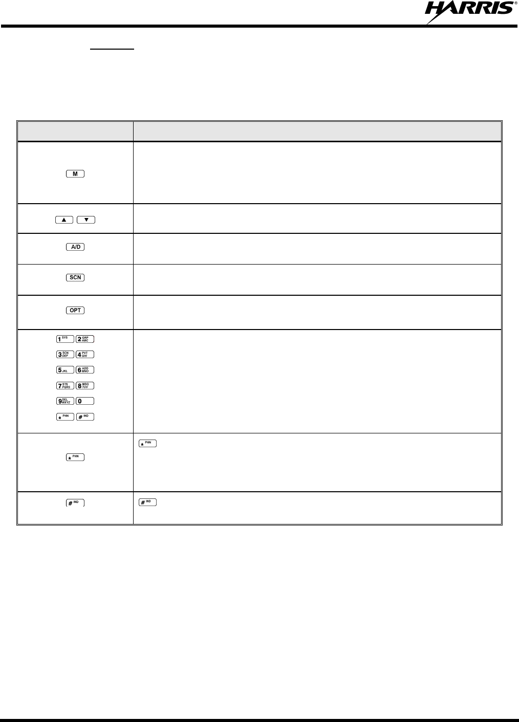
MM-013994-001, Rev. Ap1
68
9.1.2 Keypad
The keys on the keypad have special functions and are labeled using a symbol or abbreviated word
describing its primary function. Numeric entry is a secondary function of the keys. Each key is described
in Table 9-1.
Table 9-1: Keypad Functions
KEY FUNCTION
Primary function: Acts much as an “enter” button to activate a selection.
Secondary function: While in the “dwell display,” press repeatedly to scroll
through and view status display (on 2nd line) for current profile, caller, received
talk group, and channel.
Scrolls thru available menu items (see Table 9-4).
(P7350 only) Undefined in OTP mode.
(P7350 only) Toggles SCAN operation ON and OFF.
(P7350 only) Undefined in OTP mode.
(P7370 Only)
The alpha-numeric keys are used to place telephone interconnect and
individual (unit-to-unit) calls. The keys operate like a normal telephone
keypad.
Also used to enter passwords for logging into the OpenSky network, if not pre-
configured for automatic registration at power-up.
(P7370 Only)
Initiates OpenSky functions (log in, log out, selective call, telephone
interconnect call, etc.). See page 76 for additional information. It is also used
as an escape or to clear an entry (something like backspace, but it clears
everything and not only the last digit/character).
(P7370 Only) Used in conjunction with alpha-numeric keys for passwords and OpenSky
functions. See page 76 for additional information.
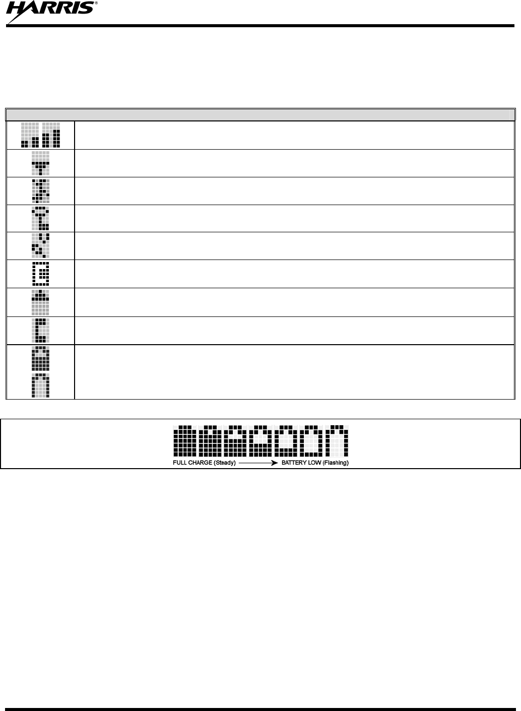
MM-013994-001, Rev. Ap1
69
9.2 RADIO STATUS ICONS
Status Icons indicate the various operating characteristics of the radio. The icons show operating modes
and conditions and appear on the third line of the display (see Table 9-2).
Table 9-2: Status Icons Descriptions
OPENSKY ICONS
Steady – Received Signal Strength Indicator (RSSI). Appears in the 1st and 2nd position of the display in OpenSky
mode.
Steady – Radio is data registered. Appears in the 3rd position of the display in OpenSky mode.
Steady – Stealth mode is enabled, all tones and the display backlight are disabled, voice is still heard. Appears in the
4th position of the display in OpenSky mode.
Steady - Radio is transmitting or receiving an encrypted voice call. Appears in the 6th position of the display.
Animated – The radio is scanning for a VTAC. Once the radio has attached to a VTAC, the icon will turn off. The icon
appears in the 7th position of the display in OpenSky mode.
VTAC Connection Indicator – Indicates the client is connected to a VTAC. Appears in the 8th position of the display in
OpenSky mode.
Steady – Indicates Scan mode is Normal or Fixed. Is not displayed when Scan mode is None. Appears in the 9th
position of the display in OpenSky mode.
Steady – Indicates Selective Call mode. Appears in the 11th position of the display in OpenSky mode.
Steady – Battery charge indicator. Appears in the 12th position of the display.
Flashing – Low battery indicator.
Figure 9-1: Full Cycle Battery Charge Indicator
The battery charge indicators illustrate approximate level only, based on battery voltage. Refer to Figure
9-1.
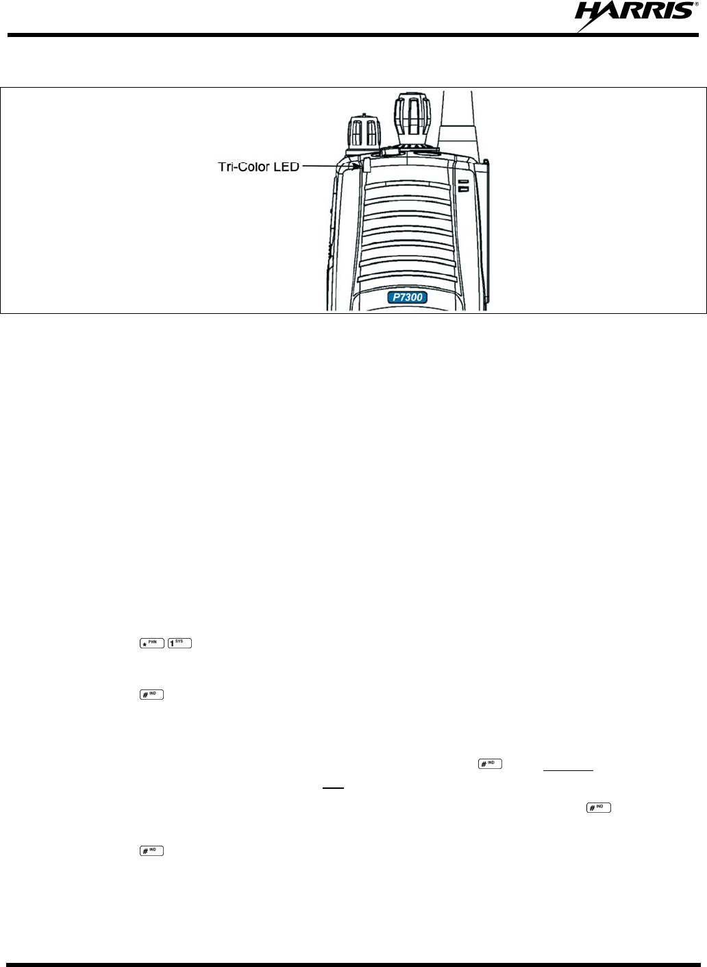
MM-013994-001, Rev. Ap1
70
9.3 TRI-COLOR LED
Figure 9-2: Tri-Color LED
The Tri-Color LED changes color to indicate radio status and is visible from both the front and top of the
radio (see Figure 9-2). The radio states reflected by the LED are:
Green: Receiving
Red: Transmitting
If the LED is flashing rapidly, the radio is receiving an emergency call. If the
LED is flashing every ½ second, the selected talk group is in the emergency state
(although not transmitting). If the selected talk group is in the emergency state,
an asterisk will be displayed next to the talk group name.
9.4 LOG IN TO THE NETWORK
Login occurs either automatically (auto registration) if the radio has a valid registration or, if enabled,
requires the user to enter a User ID and password.
The user will be prompted to “Pls Login” with the *1 login command, a User ID, and password.
1. Press *1, keys (Login command).
2. Enter the full 10-digit User ID.
3. Press the key.
4. Enter the password.
• If the radio is configured for alpha-numeric passwords and the password has consecutive
duplicate numbers (“MES33” for example), enter #, the key, between the consecutive
duplicate numbers so the radio will not interpret the entry as a letter (“D” in this example).
• If the radio is configured for numeric-only passwords, do not press the key between
duplicated numbers.
5. Press the key twice.
The User ID may be remembered from the previous log-in. (Refer to Section 9.5 for further details
regarding log-off commands.) The password will be established before the radio is put into operation.
Contact the local OpenSky network administrator for more information.

MM-013994-001, Rev. Ap1
71
If necessary, contact radio system administration personnel for log-in assistance and/or
radio-specific log-in instructions.
9.5 LOG OFF THE NETWORK
The *0## command de-registers the radio. Typically, this is automatically performed when powering
down the radio. Using this method, the User ID is remembered by the radio so only the password is
needed at next log-in. Log-off manually by pressing .
If a user is logged in, it is necessary to log-off.
9.6 PERSONALITY
As illustrated in Figure 9-3, a personality defines the profiles and talk groups available to the user. It is
the structuring of a collection of profiles and privileges established by the OpenSky network administrator
to provide the user with a comprehensive set of profiles to communicate effectively with the necessary
talk groups or individuals.
Personalities are stored on the network and downloaded over-the-air to the radio. This process is called
“provisioning.” Provisioning occurs at radio power-up (if the personality is not already stored in the
radio’s memory) and at user log-in. When changes are made to the personality, the radio is automatically
re-provisioned. Each personality can contain up to sixteen (16) profiles and each profile can contain up to
sixteen talk groups.
9.6.1 Profiles
As stated above, each profile can contain up to sixteen (16) talk groups. A profile also defines the radio’s
emergency behavior. All transmissions are made on the selected talk group (displayed on the top line of
the dwell display). The user can change the selected talk group to any of the other talk groups within the
profile.
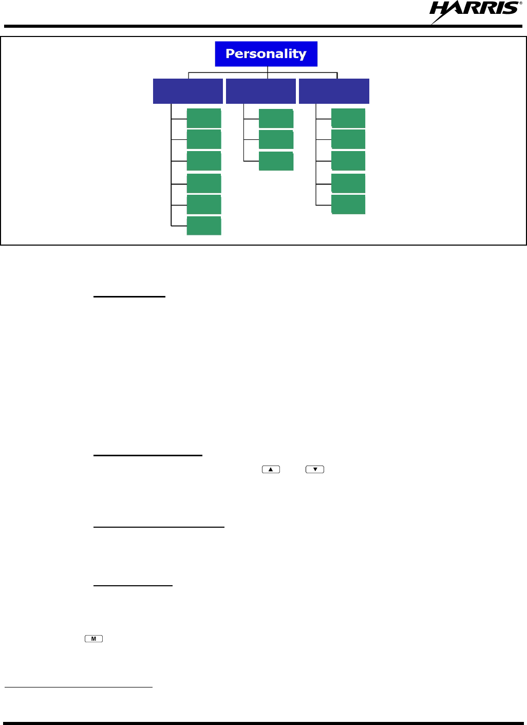
MM-013994-001, Rev. Ap1
72
TG a
TG b
TG c
TG x
TG y
TG z
TG d
TG e
TG f
TG a
TG d
TG g
TG h
TG i
TG = Talk Group
Profile 1 Profile 2 Profile 3
Figure 9-3: Personality Structure Example
9.6.2 Talk Groups
A talk group represents a set of users that regularly need to communicate with one another. There can be
any number of authorized users assigned to a talk group. Talk groups are established and organized by the
OpenSky network administrator. An OpenSky talk group is similar to a channel within a conventional FM
radio system.
9.7 OPENSKY DISPLAY OVERVIEW
The 12-character x 3-line display shows the radio status. The first two lines of the display are text lines
that change in response to user interaction with the menu buttons. Status icons appear in the bottom line
(line 3) of the display (see Table 9-2).
9.7.1 Display’s Top Line
The display’s top line of text changes as the and buttons are pressed to scroll through the
available menu options (see Table 9-4). When the dwell display is present, the selected talk group will be
displayed. Other information, such as alert messages will scroll across the top line of the display.
9.7.2 Display’s Second Line
The second line will display information such as active menu, login prompt, emergency status, and dwell
display messages as described in the following section.
9.7.3 Dwell Display
When not engaged in menu selection, the first two lines of the display default to the user-defined display,
known as the “dwell display.” The top line indicates the currently selected talk group. The second line
will display the currently selected profile, caller ID/alias1, received talk group, and current channel name.
Press the button repeatedly to scroll through and view one of these second line options.
1 Alias is a logical ID name such as “J_Smith.” The name corresponds to a user ID such as 003-542-0001.

MM-013994-001, Rev. Ap1
73
9.8 ALERT TONES
The P7300 radio also provides audible Alert Tones or “beeps” to indicate the various operating conditions
(see Table 9-3).
Table 9-3: Alert Tones
NAME TONE DESCRIPTION
Call Queued one low tone/two high tones Call is queued for processing.
Call Denied three short beeps Radio is out of coverage area or requested talk group is active.
Grant (or Go-Ahead) single short beep Sounded when resources become available for a call request
placed in the queue (if enabled) upon channel access.
If the radio roams to another site while transmitting, then it
will auto rekey and begin transmitting on that tower. It gives a
second grant tone to let the user know they have roamed.
Call Removed single long low-pitched tone Notifies the user access to the channel has been lost (out of
coverage area or pre-empted by higher-priority call).
Low Battery one low-pitched/one short mid-
pitched Low battery
Selective Alert Received four short tones Only played once to indicate a selective alert has been receive.
Emergency Alert Tone three long beeps Sounds when an emergency alert is declared.
Emergency Cleared Tone one long low-pitched tone Sounds when an emergency is cleared.
Selective Call Ring Tone a ringing tone similar to a
telephone Ringing is repeated every four (4) seconds until the call is
accepted or rejected by the radio being called or until the
network drops the call if unanswered after one (1) minute.
Roam Tone two short tones, one high-
pitched and one low-pitched Sounds when the radio transitions from one radio base station
site to another.
Out of Range Tone three brief tones If enabled via programming, sounds at a programmable
interval while the radio is in a state of persistent deactivation.
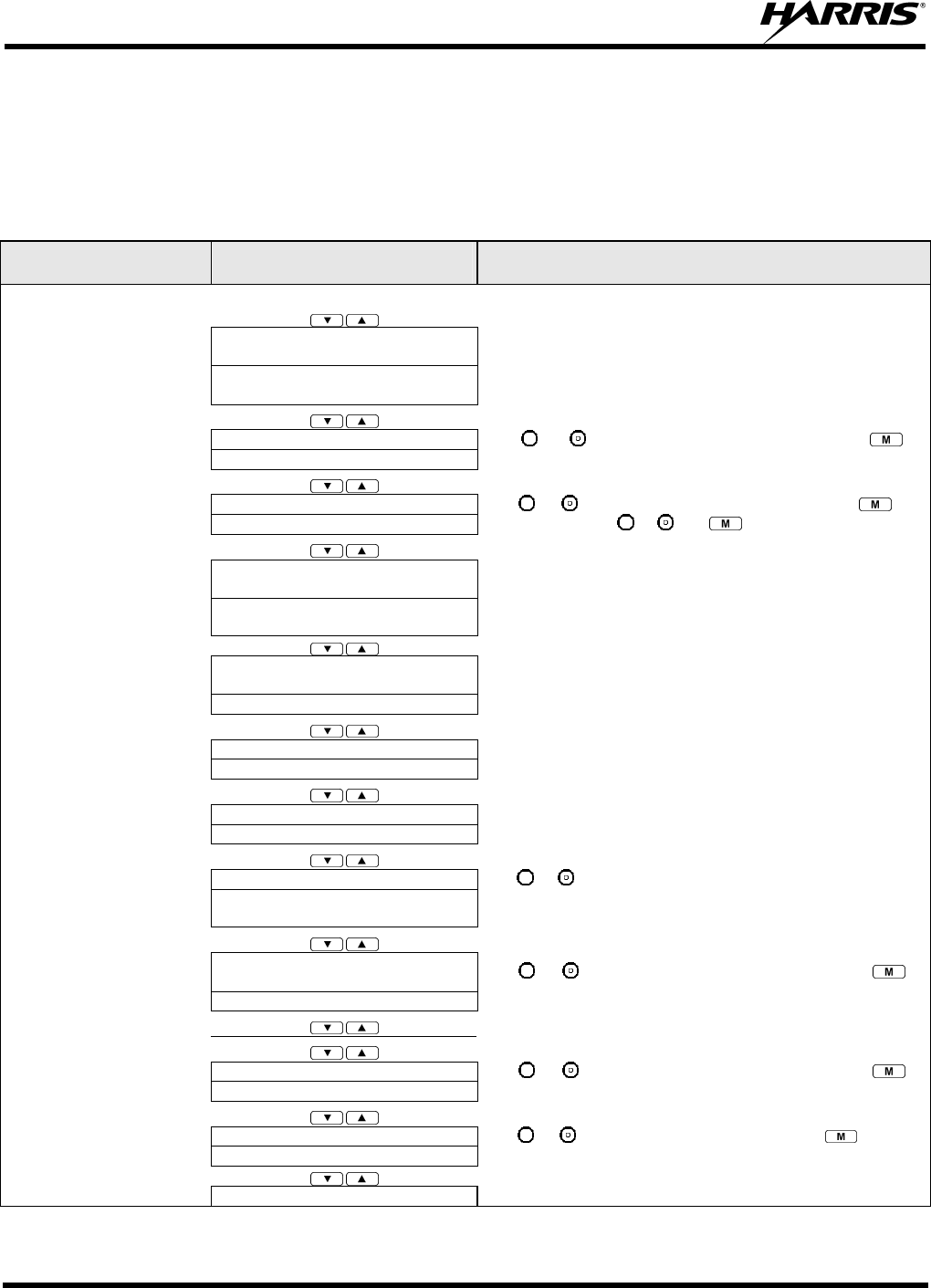
MM-013994-001, Rev. Ap1
74
9.9 BASIC MENU STRUCTURE
Table 9-4 illustrates the basic P7300 OpenSky menu structure. Menu items will vary depending upon
system programming, radio hardware, and optional configurations. All menus except the dwell display
menu can be turned off by network administration personnel.
Table 9-4: Basic P7300 OpenSky Menu Structure
Menu Name Radio Displays
(first and second lines) Usage Notes
To/From Dwell Display
registration, RF sync and
transceiver status codes
Engineering Display
(Menu may not be available
per programming.) bit-error rates
and RSSI data
Displays radio system connection data. For engineering use.
OFF/ON
Silent Emergency “SilentEmerg”
Use or to toggle between OFF/ON. Press to
enable.
available modes
Operating Mode
(e.g., OTP, OCF) “Mode Menu”
Use or to choose an available mode. Press and
confirm (Y/N) with or and again.
current latitude and longitude
(degrees:minutes:seconds)
GPS Fix
[e.g., GPS, GPS (Site), GPS
(Aged)] “GPS”
GPS latitude and longitude position of currently tuned-to
base station [“GPS (Site)”] or V-TAC (“GPS”) scrolls across
top line of the display. “GPS (Aged)” indicates VTAC
coordinates haven’t been updated for more that 2 minutes.
User ID # of user currently logged
in
User ID
“User ID”
User’s identification/name scrolls across top line of the
display (if programmed).
Radio’s IP address
IP Address “IP Address”
Radio’s Internet Protocol (IP) address scrolls across top line
of the display.
station’s call sign
Station Identification “Station ID”
Station’s identification/name scrolls across top line of the
display (if programmed).
“OFF”
Stealth Mode
(display backlight is disabled) “StealthMenu”
Use or to turn on. On P7350, press any button to turn
it off. On P7370, use Stealth Menu or press 2# to disable 2#
to disable Stealth mode.
“LOW”, “MEDIUM”, “MEDHIGH”,
“HIGH”
Treble Level
“Treble Menu”
Use or to choose speaker treble level. Press to
return to dwell display.
“<< >>”
Display Brightness “Bright Menu”
Use or to brighten or dim backlighting. Press to
return to dwell display.
“OFF”, “LOW”, “MED”, HIGH”
Side Tone Level “Side Menu”
Use or to choose side tone level. Press to return
to dwell display.
See Next Page
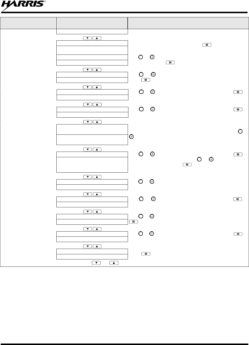
MM-013994-001, Rev. Ap1
75
Menu Name Radio Displays
(first and second lines) Usage Notes
See Previous Page
selected channel Selected Channel
(Menu may not be available
per radio programming) “ChannelMenu”
Displays the current channel. Press to return to dwell
display.
current scan mode
Scan Mode
(e.g. Normal, None, Fixed) “ScnModeMenu”
Use or to scroll between scan modes (Normal, None,
and Fixed). Press to return to dwell display.
talk group “<” Talk group
Lock Out “LockOutMenu”
Use or to choose a talk group for locking/unlocking.
Press to toggle “<” on (locked out) and off.
current priority talk group Priority 2
Talk group “Priority2”
Use or to choose Priority 2 talk group. Press to
return to dwell display.
current priority talk group Priority 1
Talk group “Priority1”
Use or to choose Priority 1 talk group. Press to
return to dwell display.
time/sender’s name/
alias/message text
Alerts Received “AlertsRcvd”
or oldest message
“No alerts” or alert message text scrolls in display. Use or
to view all messages.
current speed dial #
Alert Destination “AlertDest”
Use or to choose a speed-dial number. Press to
go to the “Alert Msg” menu. Use or to scroll through
“canned messages.” Press to send message and return
to dwell display.
current speed dial #
Speed Dial “SpeedDial”
Use or to choose a speed-dial number and press PTT
to place call.
currently active profile
Profile Selection “ProfileMenu”
Use or to choose an available profile. Press to
return to dwell display.
selected talk group
Talk group Selection “TalkGrpMenu”
Use or to choose a talk group in current profile. Press
to return to dwell display.
alert received
Emergency Dismiss “EmgDismiss”
Use or to choose emergency talk group. Press to
toggle “<” on (dismiss) and off.
selected talk group
Dwell Display (bottom line option) Press to change bottom line option.
Use and to scroll through menus.
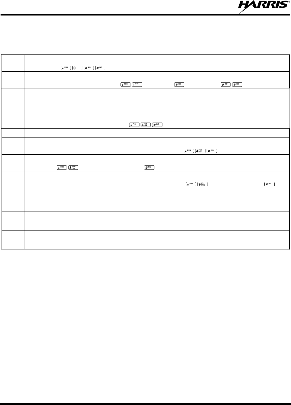
MM-013994-001, Rev. Ap1
76
9.10 KEYPAD FUNCTION COMMANDS (P7370 ONLY)
To perform a command from the keypad, use the keypad commands in Table 9-5.
Table 9-5: Keypad Function Commands
*0 Log-off command: *0## (logs the user off the system). See Section 9.5 for additional information.
Key presses:
*1 Log-in command: *1<User ID> # <Password> ## (required for encryption). See Section 9.2 for
additional information. Key presses: <User ID> <Password>
*4
Enter Scene of Incident Mode (SOI) on specified channel and band: *4<LC>#<Band># where LC
is the channel number that is being used as a SOI repeater and band is the number assigned to each
frequency band. For example, if LC 25 800 MHz (band 0) is being used for SOI, then enter
*4,25,#,0,#.
Exit SOI Mode with *4# Key presses:
*6 Go to Default Profile. Selects default profile if the radio is not voice registered.
*7 Initiate Selective Alert command: *7<Target ID>#[Choose Message]#. See Section 9.25 for
additional information. Exit SOI Mode with *4#. Command:
*8 Radio-to-Radio Call command: *8<Selective call number>#(PTT to dial).
Command: <Selective call number> then press PTT to dial
*9 Public Switched Telephone Network (PSTN) Call command: *9 <telephone number>#(PTT to
dial) See Section 9.26 for additional information. Command: <telephone number>
then press PTT to dial
*32 Begin Manual Encryption command: *32<Pre-determined Encryption Key>#
1-16 digit encryption key for 128 bit encryption; 17-32 digit encryption key for 256 bit encryption.
*33 End Manual Encryption command: *33#
*61 Initiate XCOV Mode: Extended coverage for individual users.
*62 Initiate XCOV-TG Mode: Extended coverage for talk groups.
*60 Exit XCOV or XCOV-TG Mode: Returns to the normal mode.

MM-013994-001, Rev. Ap1
77
9.11 QUICK KEYS (P7370 ONLY)
Quick Keys are a two-button sequence that provides the user with quick access to certain menu items.
Quick Keys function as a toggle for these menu items.
Table 9-6: Quick Key Sequence
QUICK
KEYS FUNCTION
1# Transition to ECP mode
If ECP code is not loaded in the radio, “No App” appears in the display
2# Toggles Stealth Mode On/Off
3#
Toggles Scan Mode On/Off (Normal/Fixed, see details below)
• If the Scan Mode is Normal when the Scan Mode is toggled Off, the Scan Mode will be
Normal when toggled On again.
• If the Scan Mode is Fixed when the Scan Mode is toggled Off, the Scan Mode will be
Fixed when scan mode is toggled On again.
• If the Scan Mode is Off when the radio boots up, the Scan Mode will be Normal when
Scan Mode is toggled On.
4#
Lights/Tones On/Off
Pressing 4# turns the TX/RX LEDs, Backlight, and Side Tones On/Off.
If any of the TX/RX LEDs, Backlight, and/or Side Tones are On, and this quick key sequence
is used, then all of the TX/RX LEDs, Backlight, and Side Tones are turned Off.
If the radio is in Stealth mode, this quick key is disabled since the user is not able to turn on
the light/tones in stealth mode.
6#
XCOV & XCOV-TG Attach/Detach
This quick key sequence is used to manually connect to a V-TAC. When attaching to a
V-TAC, the radio’s programming determines whether to attach to the V-TAC in XCOV or
XCOV-TG mode.
1. If the user attaches to a V-TAC manually, using the *61# or *62# command sequence, the
radio is understood to be attached and this quick key sequence will detach the radio from
the VTAC.
2. If the user detaches manually from a V-TAC using the *60# command sequence, the radio
is understood to be detached and this quick key sequence will attach the radio to a VTAC.
3. At bootup, the radio is understood to be detached from a VTAC. If a radio automatically
attaches to a VTAC, the radio is still understood to be detached from a VTAC and will
attempt to attach to a VTAC.
4. If a radio manually attaches to a VTAC and then is automatically detached from a VTAC, the
radio is still understood to be attached to a VTAC and will attempt to detach from a VTAC.
9.12 LOCK/UNLOCK THE KEYPAD
1. Press and hold the button.
2. While holding the button, press the button on the side of the radio.
9.13 DUAL-TONE MULTI-FREQUENCY (P7370 ONLY)
Dual-Tone Multi-Frequency (DTMF) is the system used by touch-tone telephones. DTMF assigns a
specific tone frequency to each key so a microprocessor can easily identify its activation. This allows for
specific tasks such as entering a user ID and password, or selective calling.
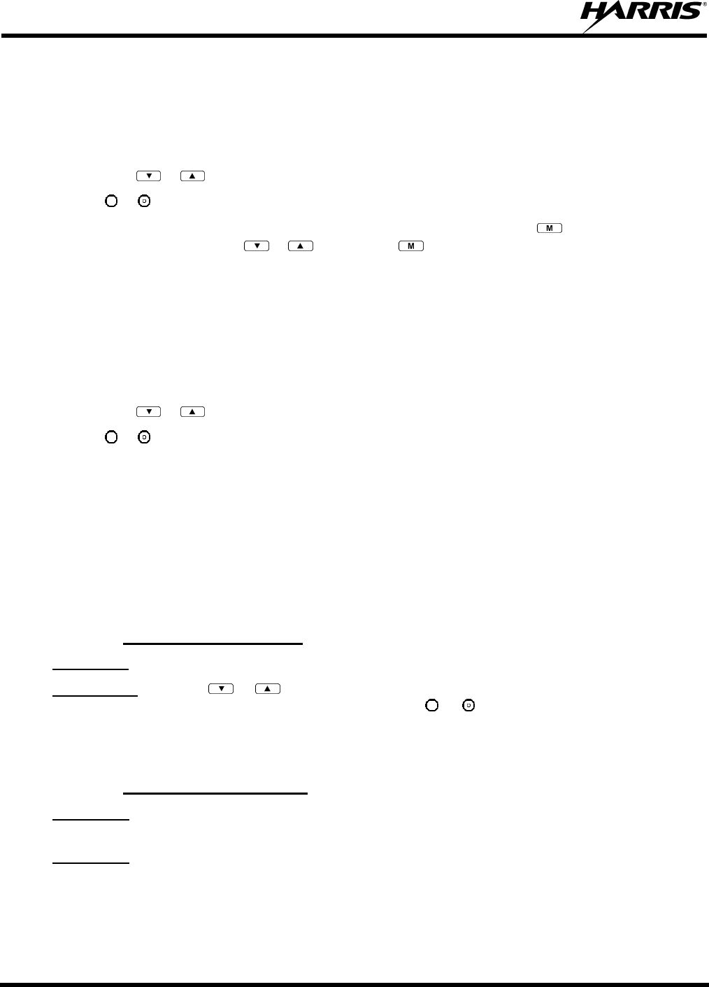
MM-013994-001, Rev. Ap1
78
When a key on the DTMF keypad is pressed, the DTMF tone is played through the radio’s speaker.
9.14 CHANGING THE ACTIVE PROFILE
The radio can store up to sixteen (16) standard profiles, one of which is the currently active profile. To
change the currently active profile:
1. Press the or buttons until “ProfileMenu” is displayed.
2. Use or to scroll through the list of available profiles.
3. Profile becomes active when selected for longer than 2 seconds, when the is pressed, or when the
menu is changed using the or button. Press to activate the selected profile.
9.15 CHANGING THE SELECTED TALK GROUP
Each profile stored in the radio can have up to sixteen (16) talk groups. One talk group within the
currently active profile is set as the “selected talk group.” To change the selected talk group, turn the
Group Selection knob on top of the radio.
9.16 ADJUSTING DISPLAY AND BUTTON BACKLIGHT BRIGHTNESS
1. Press the or buttons until “Bright Menu” is displayed.
2. Use or to brighten or dim the display and button backlighting.
9.17 STEALTH MODE
For some users, it is important to be able to turn off the radio’s display lights and side tones, but not the
radio traffic. For example, in covert operations, lights and sounds could inadvertently expose an
otherwise unobservable radio user. For this purpose, the radio has a Stealth feature that disables the radio
display light, indicator light, and audible side tones.
When Stealth Mode is on, the radio continues to scan the programmed list of talk groups and the user can
key-up on the selected talk group.
9.17.1 Enabling Stealth Mode
P7370 only: Quick Key combination 2# toggles Stealth Mode on and off.
Both models: Press the or buttons to scroll through menus until “StealthMenu” appears in the
display. To immediately activate Stealth Mode press the or button once. This activates Stealth
Mode, exits the Stealth Menu, and returns to the Dwell Display.
The display lights, indicator lights, and side tones are disabled. The Stealth Mode icon is displayed.
9.17.2 Disabling Stealth Mode
P7370 only: To re-enable all lighting, side tones and exit Stealth Mode, press Quick Key combination 2#
again. The radio returns to the Dwell Display.
P7350 only: To re-enable all lighting, side tones and exit Stealth Mode, press any key other than PTT or
the Emergency button. The radio returns to the Dwell Display.
The display lights, indicator lights, and side tones are re-enabled. The Stealth Mode icon disappears.
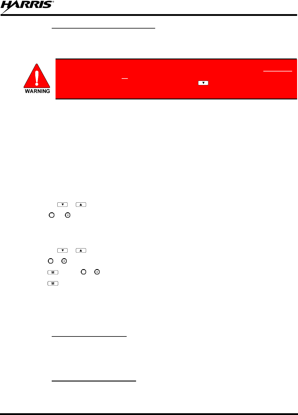
MM-013994-001, Rev. Ap1
79
9.17.3 Stealth Mode using A/B Switch
It is also possible to enable and disable Stealth Mode using the A/B Switch, if so programmed.
Depending on programming the switch in one position will enable Stealth Mode and in the other position,
disables it.
With Stealth Mode on the P7350 model radio, pressing any radio button (other than
the mic’s PTT button or the Emergency button) on the front panel will immediately
turn Stealth Mode off. For example, pressing the button on the front panel will
turn stealth mode off.
9.18 ADJUSTING SIDE TONE AUDIO LEVEL
The radio sounds confirming tones called “side tones” when its buttons are pressed. Most users find this
audible confirmation helpful when navigating the menus. Side tone audio level can be adjusted or turned
completely off using the “Side Menu.”
For covert operations, it may be necessary to turn off side tones. For safety’s sake, turning off the radio
during covert operations is not recommended.
If the radio is operating properly but side tones are not heard when the menu buttons are pressed, the side
tones are probably turned off. To turn them back on, access the “Side Tone” menu and select a setting
other than “off.”
Use the following procedure set side tone level:
1. Press the or buttons to cycle through the menu until “Side Menu” is displayed.
2. Press or to change to the desired level (Off, Low, Medium, and High). To turn side tones
completely off, use the “Off” setting.
9.19 CHANGE OPERATING MODE
1. Press the or buttons to cycle through the menu until “Mode Menu” is displayed.
2. Press or to select the desired operating mode.
3. Press and use or to select Y or N.
4. Press again to make selection and return to the dwell display.
9.20 RECEIVING AND TRANSMITTING VOICE CALLS
As soon as the radio completes the initialization sequence and registers on the OpenSky network, the user
will begin to hear calls from the talk groups in the active profile, if available.
9.20.1 Receiving a Voice Call
No action is required on the part of the user.
The caller’s alias is only shown when the selected talk group matches the received talk group. Otherwise,
the name of the received talk group is displayed.
9.20.2 Transmitting a Voice Call
1. Select the desired talk group.
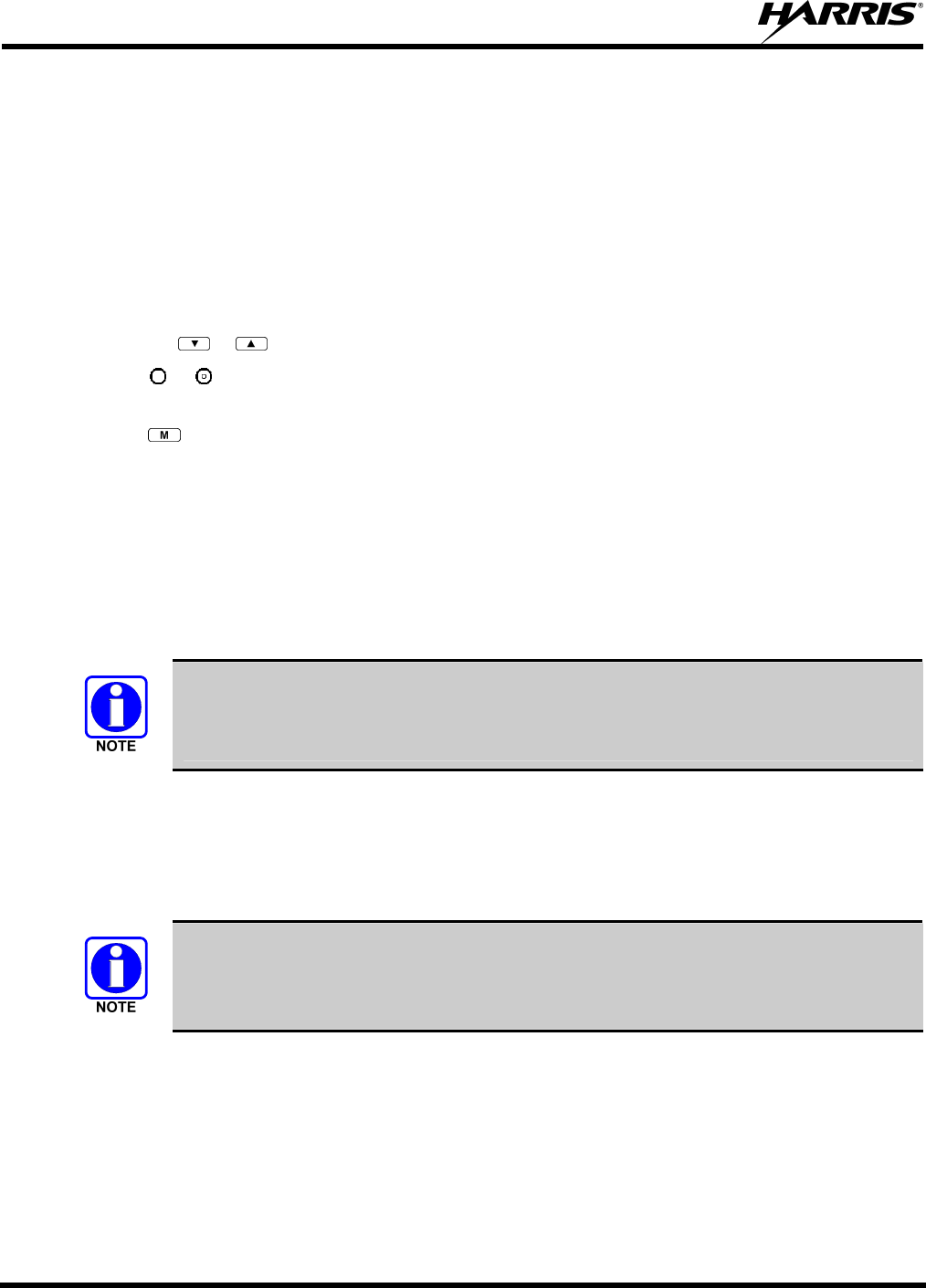
MM-013994-001, Rev. Ap1
80
2. Depress and hold the PTT button, wait a couple of seconds. If programmed by the administrator, a
grant tone will be sounded.
3. Begin speaking into the microphone in a normal voice.
4. For maximum clarity, hold the radio approximately 2 inches from your mouth. Take care not to cover
up the microphone while speaking.
5. Release the PTT button to terminate an outgoing voice call.
9.21 ADJUSTING AUDIO TREBLE LEVEL
The tone of received signals can be adjusted using the radio’s “Treble Menu.”
1. Press the or buttons to cycle through the menu until “Treble Menu” is displayed.
2. Press or to increase or decrease level. There are four levels available: low, medium, medium-
high, and high.
3. Press or wait a few seconds to return to the dwell display.
9.22 TALK GROUP LOCK OUT
There are two ways to focus voice communications by suppressing calls from talk groups in the active
profile.
• Non. By changing the Scanning Mode to “None” only the selected talk group is scanned.
• Lock Out. By locking out selected talk groups, background noise or chatter can be eliminated and
scanning resources can be focused on just those groups whose calls you wish to monitor.
Lock out is a listening (receive) function and only blocks received calls on locked out talk
groups. Lock out does not affect transmit capability. “None” and “Lock Out” do not
apply to recent emergency lock outs.
Only talk groups in the active profile can be locked out, since they are the only talk groups whose voice
calls can be heard on the radio. Talk group lock out is a scan-related feature. With lock out, one or more
talk groups in the active profile can be temporarily disabled from being scanned. Calls are not received on
locked-out talk groups. Lock out settings are not retained between profile changes or when the radio is
power cycled.
If the Scan Mode is “Fixed,” P1 and P2 groups CANNOT be locked out. See Section 9.23
for more information.
The default emergency and emergency-capable talk groups can be locked out if they are NOT in an
emergency state. If a talk group is locked out and is subsequently changed to the currently selected talk
group, it will automatically be unlocked by the radio so the user can hear calls on the talk group. The
radio may be configured so all talk groups are automatically locked out by default. In this case, they must
be manually unlocked, if desired.
MM-013994-001, Rev. Ap1
81
9.22.1 Lock Out a Talk Group
1. Use the or buttons to scroll through the menu choices until “LockOutMenu” appears in the
display.
2. Use the or keys to scroll through the list of talk groups, if any, until the user group you want to
lock out appears in the display.
3. Press the key to select the lockable talk group.
4. “<” appears next to the locked out talk group.
9.22.2 Unlock a Talk Group
1. Use the or buttons to scroll through the menu choices until “LockOutMenu” appears in the
display.
2. Use the or keys to scroll through the list of talk groups, if any, until the user group you want to
unlock appears in the display.
3. Use the key to unlock the displayed talk group.
• Changing the active profile removes any lockouts you have made.
• Turning off the radio removes any lockouts you have made.
9.23 SCANNING
9.23.1 Selecting Scan Modes
Three scanning modes are available for the radio, but only one can be active at any time. Changing the
scanning mode changes the way the radio scans voice calls for all of the profiles in the radio personality,
no matter which profile is or becomes active.
The choice of scanning mode broadens or narrows the span of communications with all the groups in
profiles you listen to, but does not affect your interaction with those groups you talk with.
The scanning modes available for selection may be limited to a subset of the three scanning modes by the
administrator.
MM-013994-001, Rev. Ap1
82
Table 9-7: Scan Modes
SCAN
MODE EXPLANATION
None
Eliminates distractions.
Full communications (listen and talk) with the active talk group.
No calls received from other talk groups.
Normal
This is the default setting.
The user can scan all talk groups in the active profile that are not locked out as long as there is demand on the
site.
Priority (P1 and P2) groups are user selectable.
Receive calls from more than one talk group, if available from the current site.
Allows dragging of the selected talk group, P1, P2, and default emergency talk groups to the site on which
the radio is registered. (If other calls are available at the site, they also can be heard but they will not be
actively dragged.)
The default emergency talk group, as well as any emergency-enabled talk groups, is only dragged if it is in
emergency mode.
Fixed
The priority groups are fixed to the selected profile’s pre-defined P1 and P2 groups (configured via the
UAS). In this mode, P1 and P2 groups CANNOT be locked out.
The user can scan all talk groups in the active profile that are not locked out, as long as there is demand on
the site.
Allows dragging of the P1, P2, and selected talk group to the site on which the radio is registered. If other
calls are available at the site, they can also be heard, but they will not be actively dragged.
The default emergency talk group, as well as any emergency-enabled talk groups, is only dragged if in
emergency mode.
The scanning mode choice remains in effect until it is changed. Even if the radio is turned off, the current
scanning mode selection is saved for the next use.
9.23.2 Checking or Changing Active Scan Mode
9.23.2.1 Setting the Scan Mode
1. Press the or buttons until “ScnModeMenu” appears in the display.
2. Use the or keys to scroll through the list of modes until your choice appears: Normal, None, or
Fixed.
3. Press the key to activate the scan mode selection and return to the dwell display.
9.23.2.2 Duration of Scanning Mode Selections
Scanning Mode selections survive power down. At startup, the radio defaults to the scanning mode of set
during last use. The last selection made remains in effect until a new selection is made from the Scan
Mode menu.
9.23.3 Scanning Priority
The following lists the scanning priority order (from highest to lowest):
• Selected talk group in emergency state.
• Default emergency group in emergency state.
MM-013994-001, Rev. Ap1
83
• Selected talk group.
• Emergency capable group in emergency state.
• Priority 1 talk group.
• Priority 2 talk group.
• Other (non-priority).
9.23.3.1 Changing Scan Priority
1. Press the or keys until “Priority1” or “Priority2” appears in the display (Priority1 group has
higher priority than the Priorty2 group).
2. Press the or button until the desired talk group is displayed.
3. Press the key to select and activate the selection. The radio automatically returns to the Dwell
Display.
• Changing the priority of a listen group does not change your talk group.
• You set priority for two talk groups, but only in the selected profile.
• The scanning priority settings are reset to the default values when the radio is turned
off.
9.24 MAKING SELECTIVE CALLS
Selective calling is the capability for two voice radio units to obtain and use an independent talk path for a
unit-to-unit call. A properly equipped radio can initiate a selective call to any radio in the system that is
also programmed for selective calls.
In the OpenSky system, a radio can be configured to initiate selective calls through a pre-programmed list
in memory called a speed dial list. Alternatively, a properly equipped radio can initiate a selective call to
any radio in the system by entering the ten-digit User ID (similar to a telephone number) of the target
radio. Some radios are configured to only receive (not initiate) selective calls.
Selective calls are terminated if an emergency is declared. The network limits selective
calls to ten (10) minutes maximum.
If a Selective Call is attempted without registration, “No Priv” is displayed.
9.24.1 Manually Dialing a Selective Call (P7370 Only)
1. Enter *8, the User ID number of the user being called, and the # key (no dashes or spaces). Note that
this feature must be enabled by the administrator.
*8<destination user id>#
<destination user id>
MM-013994-001, Rev. Ap1
84
A shortened User ID number can be dialed using the following guidelines:
• If the radio being called is in the same region and agency – enter only the last four digits.
• If the radio being called is in the same region, but a different agency – enter the last seven digits.
• If the radio being called is in another region or if the area is unknown – enter all ten digits.
2. Press PTT (and release) to ring the other user.
The ring tone is sounded.
If the other user accepts the call, the called user’s alias will appear in initiating caller’s display. The
two are now in a unit-to-unit call until one ends the call, the call is terminated due to an initiated
emergency, or the maximum time limit of ten (10) minutes is reached.
If the called radio is busy, “BUSY” will appear in the second line of the display.
9.24.2 Selective Call Using Speed Dial
Speed dial numbers are defined and provisioned by the OpenSky network administrator and
cannot be manually entered into the radio by the user. Contact the administrator if changes
to the speed dial list are required.
1. Scroll through the Menu options using the or button until “Speed Dial” appears in the second
line of the display. Using the or keys, scroll through the pre-programmed speed-dial numbers
until the desired number appears in the display and press the PTT button.
OR
2. Press and hold a key associated with a given number for more than three seconds. For example, press
and hold the to open the Speed Dial Menu and display the number assigned to that key in the
speed dial list. Press the PTT button.
A ring tone is sounded.
If the other user accepts the call, the called user’s alias will appear in initiating caller’s display. The two
are now in a unit-to-unit call until one ends the call, or the call is terminated due to an initiated
emergency.
If the called radio is involved in another selective call, “BUSY” will appear on the second line of the
display. “Unavailable” is displayed when the call has not been answered after a 1 minute timeout or when
the other party is not registered on the network.
9.24.3 Accepting a Selective Call
1. The radio will ring (like a telephone), indicating you are receiving a Selective Call.
2. Press the , or the or buttons to accept the incoming selective call.
3. “CONNECT” will appear in the display, followed by “Lim 10 Min.” “SEL CALL” and the alias of
the caller appear in the display once the call is established.
9.24.4 Rejecting a Selective Call
When a Selective Call is being received (the radio is ringing), you can reject the call by pressing either of
the or buttons or the key, or by turning the Voice Group Selector Control knob. The call will be
rejected and “Reject” appears on the callers display.
MM-013994-001, Rev. Ap1
85
9.24.5 Terminating a Selective Call
Terminate a Selective Call (call must be active) by pressing the or buttons or the key, or by
turning the Voice Group Selector Control knob. “HANGUP” will appear in the display followed by the
active talk group.
9.25 SELECTIVE ALERTS
Selective alert messaging is an OTP feature that allows one of up to eight (8) pre-programmed (canned)
text messages to be sent from one radio to another. The sender specifies a destination (receiving) radio,
selects one of the pre-programmed text messages, and then transmits it to the destination radio. The
message delivery system adds sender and time-of-day information and forwards the message to the
destination (receiving) radio. The sending radio receives a brief message noting the status of the
transmission.
Received messages are stored in the radio until deleted or until the radio is rebooted. Received messages
do not survive a reboot.
9.25.1 Defining Messages
All selective alert messages are pre-defined. The messages are programmed and provisioned remotely by
your OpenSky system administrator. The radio user cannot create selective alert message content. The
entire selective alert message, including the abbreviation, can be up to 200 characters long.
When sending a selective alert message, the radio may display one of the following status messages
(Table 9-8).
Table 9-8: Status of Selective Alert Messages
STATUS MESSAGE DEFINITION
Delivering Select Alert message transmit attempt
Busy Too busy – Try again
Dest Down Receiving radio not logged on – Not registered
Not Reg Transmitting radio not logged on – Not registered
Delivered Transmission complete
Unreachable No response
Partial Transmission interrupted
9.25.2 Sending a Message
The sending process has three steps. First select the destination radio’s User ID, then select the alert
message, and finally send the message.
9.25.2.1 Selecting a Destination Using the Keypad (P7370 Only)
1. Using the keypad, enter *7, the keys.
At the “AlertDst” prompt, enter the full User ID of the unit to send the message. A shortened User ID
number can be dialed using the following guidelines:
• If the radio being called is in the same region and agency – enter only the last four digits.
• If the radio being called is in the same region, but a different agency – enter the last seven digits.
MM-013994-001, Rev. Ap1
86
• If the radio being called is in another region or if the area is unknown – enter all ten digits.
2. Press the key to activate the selection.
3. Use the and buttons or the and buttons to scroll through the available messages until the
desired message is displayed.
4. Press the or key to send the message.
5. Observe Status Messages (Table 9-8) to ensure proper delivery.
9.25.2.2 Selecting a Destination Using the Menu
1. Using the or key, scroll through the menu until “AlertDst” (Alert Destination) appears.
2. Use the or button to scroll through the list of User IDs until the desired destination is displayed
and press the key.
3. Use the or buttons to scroll through the available messages until the desired message is
displayed.
4. Press the key to send the message.
5. Observe Status Messages (Table 9-8) to ensure proper delivery.
9.25.3 Receiving a Message
When a selective alert message is received by a radio, a four-beep tone is heard. The tone is heard only
once, but the message “NEWALRT” alternates with the talk group on the main display. Up to 8 received
messages can be stored. If a ninth message is received, the first (oldest) message is automatically deleted
to make room for the new message.
Received messages are displayed with the time and source information.
To display a Selective Alert Message:
1. Using the or button, scroll through the menu items until “Alerts Rcvd” appears. The oldest
message is displayed and scrolls across the top line of the display.
2. The message includes the time, the User ID, and alias of the sender along with the message.
3. To view the next message, press the or button to go forward or backwards.
9.25.4 Deleting a Selective Alert Message
1. Display the message.
2. Press the key and or to select Y or N.
3. At the “Delete? Y” prompt, press the key. The message will be deleted.
Received messages cannot be saved.
9.26 MAKING INTERCONNECT CALLS (P7370 ONLY)
1. Using the keypad, enter *9, followed by the telephone number being called, and the # key (no dashes
or spaces).
MM-013994-001, Rev. Ap1
87
*9<telephone number>#
Wait a couple of seconds and press and release the PTT button to initiate the call. An initial ring tone
will sound to indicate signal call initiation. Once the gateway picks up the call, the ring tone will
change. Press and hold the PTT and talk normally then release the PTT to listen.
2. To hang up the call, press the button or the key.
9.27 EMERGENCY COMMUNICATIONS
The P7300 portable radio is capable of sending an emergency alert and making emergency calls on the
network. The OpenSky system handles emergency calls with the highest priority, allowing you or the
people you serve to get needed help.
Emergency call and alert capability for a profile is configured by the system administrator.
The radio that initiates an emergency alert emits a signal of 3 distinct beeps that only goes
to the dispatch console.
Table 9-9: Emergency Calls vs. Emergency Alerts
EMERGENCY ALERT EMERGENCY CALL
An Emergency Alert message is
sent to the dispatcher console. The
dispatch console plays an
emergency tone when it receives
the message.
An Emergency Alert message is sent to the dispatcher console. All peers
(radios and consoles) and the dispatch console play the emergency tone
whenever an emergency call is detected. An emergency tone plays for
each new emergency, or when a profile is changed, (assuming there is an
emergency on one of the talk groups for the new profile).
If the orange LED is flashing rapidly, the radio is receiving an
emergency call. If the LED is flashing every ½ second, the selected talk
group is in the emergency state (although not transmitting). If the
selected talk group is in the emergency state, an asterisk displays next to
the talk group name.
No emergency audio (voice)
transmission (hot-mic) capability
available (per programming by
system administrator)
In addition to the Emergency Alert signal, the microphone goes hot for a
predetermined length of time to allow for emergency audio (voice)
transmission. The radio declaring the emergency has channel access
priority. Note that the User can also use the PTT after the pre-determined
hot-mic audio transmission, or during to extend the initial hot-mic audio
transmission.
9.27.1 Declaring an Emergency Call or Alert
1. Press the red emergency button on the radio to enter emergency mode.
The emergency behavior for the selected profile is configured by the network
administrator. This determines whether pressing the Emergency button sends an
Emergency Call or just an Emergency Alert. An Emergency Alert is always part of and
sent with an Emergency Call.
MM-013994-001, Rev. Ap1
88
If the active profile of the unit initiating the emergency is configured to Emergency Alert, the three-
beep emergency alert signal is sent only to the dispatcher console.
If the active profile of the unit initiating the emergency is configured to Emergency Call, the three-
beep emergency alert signal is sent to the dispatcher console and to all other radios within the selected
talk group. The default emergency talk group becomes the selected talk group. The display will
alternate between the emergency talk group name and “EMERGENCY” to indicate that the
emergency has been initiated.
2. The microphone is hot (open mic) for a programmed amount of time in order to send your voice out
on the emergency talk group.
All of the radios in the emergency talk group hear your call and see the emergency talk group displayed
on their radio.
9.27.2 Receiving an Emergency Call
Initially, when receiving an emergency call, the radio sounds the emergency tone (three short high-
pitched tones).
The radio will flash “EMERGENCY” and display the alias of the user that triggered the emergency or the
alias of the talk group (if the incoming talk group is the selected talk group of the receiving radio).
With “None,” only the emergency tone is heard, not the initial open mic transmission.
To dismiss or ignore the emergency, refer to Section 9.27.3.
9.27.3 Dismissing an Emergency
The “Dismissing an Emergency” function allows you to “ignore” an emergency declared by another user.
An emergency is dismissed for a configurable amount of time (default = 5 minutes).
1. After receiving an emergency call, press the or button until you see “EmgDismiss.”
2. Press the to toggle “<” on (dismiss) and off. This works in similar fashion to the lock out menu.
The emergency dismiss timer is cleared when the emergency is cleared.
9.27.4 Clearing an Emergency Call or Alert
Check with your system administrator to ensure that your radio is configured with the
ability to clear an emergency.
MM-013994-001, Rev. Ap1
89
1. Press to declare an emergency. To clear an emergency, press and hold Option 2 button . While
holding , press the emergency button. Release both buttons when the “emergency cleared” tone
sounds.
2. The radio returns to your default selected talk group. The “EMERGENCY” display is removed from
the main screen.
If the radio is in stealth mode, clearing the emergency will cause the radio to exit stealth
mode.
9.28 DYNAMIC REGROUPING
Dynamic regrouping requires that the network administrator determine which radio users should be
formed into an impromptu talk group to respond to particular emergency conditions.
The administrator will edit the personalities of the affected radios to include an emergency profile and
then page the affected radios to re-register with the network to receive their edited personalities.
In response, affected radios automatically re-register to receive their edited personalities. During re-
registration, subscriber equipment will default to the emergency profile selected by the administrator.
9.29 GPS COORDINATES
The radio’s current latitude and longitude coordinates may be displayed using the “GPS” menu. The
following procedure assumes a GPS antenna is connected to the radio and it is receiving adequate signals
from GPS satellites.
1. Press or until the “GPS” menu appears in the display. Current GPS coordinate latitude and
longitude data continuously scrolls in the top line of the display in a degrees:minutes:seconds format.
2. Press or to change to another menu.
If the internal GPS receiver’s data is expired (30 minutes or more) or unavailable, the
radio uses the serving base station’s coordinates [GPS (Site) is displayed]. The GPS Menu
will also indicate if the data is aged (2 minutes or more) [GPS (Aged) is displayed].
9.30 V-TAC OPERATION
9.30.1 Extended Coverage Modes (“XCOV” and “XCOV-TG”)
In addition to all standard portable radio operating capabilities, Extended Coverage adds the V-TAC’s
bridging (vehicular repeat) functionality for accessing the OpenSky radio network. Each portable radio
connected to the V-TAC using Extended Coverage is considered a “client” on the V-TAC. Extended
Coverage benefits portable radio users since it allows them to get network connectivity using the
V-TAC’s higher transmit output power and better antenna system.
The V-TAC supports two Extended Coverage modes: Extended Coverage for individual users (display
reads “XCOV”) and Extended Coverage for a talk group (display reads “XCOV-TG”). Typically,
Extended Coverage is used after the vehicle’s operator has exited the vehicle with a portable radio unit
and the portable unit requires this bridging functionality to access the OpenSky radio network.

MM-013994-001, Rev. Ap1
90
The V-TAC takes advantage of OpenSky’s TDMA capability to eliminate interference between its local
and network radio links when operating in an Extended Coverage mode (XCOV or XCOV-TG), an
undesirable characteristic of many traditional vehicular repeater systems. Because the V-TAC employs
this technology, interference on the network and local radio links is minimized.
A V-TAC in XCOV or XCOV-TG mode sends its alias to clients. The alias is displayed in the second
line of the dwell menu of the client, (“VA <alias>”). The client must be connected to a V-TAC running
version OTP14.4 or for the V-TAC to provide the alias to the client. If the client is connected to a
V-TAC running version OTP14.3.1 or earlier, the client displays “VA None.”
9.30.2 Change Between Extended Coverage Modes
By default, the specific Extended Coverage mode utilized, either XCOV or XCOV-TG, is determined by
commands sent to the V-TAC and portable radios from the system administrator or radio installation
personnel. In other words, these commands determine which Extended Coverage mode the V-TAC and
radios normally use and determine the access method that must be employed by a portable radio to
connect to the V-TAC. After commands of this type are sent to the V-TAC and portable radios, each must
be rebooted (powered off and then back on) before the change takes effect.
A radio can manually override this command-determined default mode by entering *61# or *62# or by
using the Client Mode menu option. Command *61# sets the radio to use the XCOV mode and *62# sets
the radio to use the XCOV-TG mode. However, the connection will only be successful if the V-TAC
operating mode matches the manually selected portable V-TAC mode.
9.30.3 Radio Limitations Using Extended Coverage Modes
Connecting a portable radio to a V-TAC introduces minor functional limitations. See the following
sections for a listing.
9.30.3.1 Limitations Using Both XCOV and XCOV-TG
Portable radios connected to the V-TAC using either of the Extended Coverage Modes, XCOV or
XCOV-TG, will not channel-scan unless they lose radio frequency contact with the V-TAC. If manually
enabled, radios will not scan network channels.
9.30.3.2 Limitations Using XCOV-TG
The following portable radio keypad functions are disabled when the radio is connected to the V-TAC
using the XCOV-TG mode: log-off, manual log-in, alerts, selective calls, PSTN calls, and speed dial
calls.
The following portable radio menus are disabled when the radio is connected to the V-TAC using the
XCOV-TG mode: alert destination, alert message, alert received, priority talk group, and scan mode. In
addition, the user cannot change talk group or profile.
9.30.4 Use XCOV Mode
The Extended Coverage for individual users (XCOV) mode allows up to eight (8) client radios to connect
to the V-TAC. The radios have full radio functionality including selective calling and mobile data.
With the Extended Coverage for individual users’ (XCOV) mode, V-TAC configuration defines which
portable radios are permitted V-TAC access. The radio will automatically connect to a V-TAC if it
cannot find a network channel. The radio can also be manually connected to a V-TAC as indicated with
the *61# and *62# commands, each determined by the system administrator in the radio configuration.
MM-013994-001, Rev. Ap1
91
9.30.4.1 Manually Accessing the XCOV Mode
P7370 Model Radios
1. Press *61# to manually access XCOV mode.
2. Press *60# to disconnect from XCOV mode.
All P7300 Model Radios
1. Press or until the Client Mode menu appears.
2. Press or until XCOV is displayed.
3. Press to confirm mode selection. The radio reverts to the dwell display and the V-TAC icon is
displayed.
9.30.5 Use XCOV-TG Mode
When using the XCOV-TG mode, up to thirty (30) client radios can connect to the V-TAC. However,
unlike XCOV, radios connected using XCOV-TG are limited to communicating only on the XCOV-TG
talk group and emergency communications. Advanced features such as selective calling and mobile data
operations are not available to the XCOV-TG connected clients.
The talk group used for XCOV-TG communications is the talk group that was selected at the V-TAC
when it entered XCOV-TG mode. Before a radio can connect to the V-TAC, the talk group must be
selected on the P7300. If this talk group is not provisioned in the radio’s personality, the radio cannot
connect to the V-TAC via the XCOV-TG mode. While connected to the V-TAC via XCOV-TG, a
different talk group or profile cannot be selected.
When a portable radio is connected to the V-TAC via XCOV-TG, the V-TAC forwards only the network
voice traffic on the XCOV-TG talk groups.
9.30.5.1 Manually Accessing the XCOV-TG Mode
For the Extended Coverage for a talk group mode (XCOV-TG), a portable radio user is granted access
and connects to the V-TAC by simply selecting the same Talk Group that the V-TAC had selected when
it entered the XCOV-TG mode. Contact the system administrator for questions regarding these aspects.
During XCOV-TG mode operations, the V-TAC will not disconnect portable radios connected to it. A
portable radio user must manually disconnect from the V-TAC by pressing *60 # on the radio’s keypad.
However, if the V-TAC is switched out of the XCOV-TG mode, all portable radios will be automatically
disconnected from the V-TAC. The radios will continue to look for another V-TAC until manually
disconnected (*60#).
P7370 Model Radios
• Press *62# to manually access XCOV-TG mode.
• Press *60# to manually disconnect XCOV-TG mode.
All P7300 Model Radios
1. Press or until the Client Mode menu appears.
2. Press or until XCOV-TG is displayed.
3. Press to confirm mode selection. The radio reverts to the dwell display and the V-TAC icon is
displayed.
MM-013994-001, Rev. Ap1
92
9.30.6 Use Scene-of-Incident Mode
The Scene-of-Incident mode (SOI) is user-selectable. The SOI mode provides a local repeater function
(V-TAC) with no network connection.
CAUTION
When operating in the SOI mode, the radio is disconnected from the OpenSky network.
Therefore, communications with radios and dispatch personnel on the network is not
possible.
SOI Mode, Manual Channel Entry (P7370 Model Only)
1. Press *4#.
2. The radio prompts for the channel. Enter the channel number and press to confirm channel.
3. The radio prompts for the band. Table 9-10 lists valid bands and their definitions. Enter the number
assigned for the desired frequency band and press to confirm.
4. The radio reverts to the dwell display. If accepted, you will be switched off the network, and be
communicating locally through the V-TAC.
Press *40# or or use the Client Mode menu to return to normal
operation (Network Mode). The personality and profile in use at the time the radio entered SOI mode is
restored.
SOI Mode, Manual Channel Entry (All P7300 Models)
1. Press or until the Client Mode menu appears.
2. Press or until SOI is displayed.
3. Press to confirm mode selection.
4. Press or until “Manual Select Chan” is displayed and press .
5. Press or to edit the right-most digit and press to advance to the next digit. Repeat until the
desired channel is entered.
6. The radio then prompts the user to edit the band. Table 9-10 lists valid bands and their definitions.
Press or to edit the number assigned to the frequency band and press to confirm and enter
the SOI mode.
Use the Client Mode menu to return to normal operation (Network Mode). The personality and profile in
use at the time the radio entered SOI mode is restored.
SOI Mode, Pre-Programmed Channel Selection (All P7300 Models)
1. Press or until the Client Mode menu appears.
2. Press or until SOI is displayed.
3. Press to confirm mode selection.
4. Press or scroll through a list of pre-programmed channels.
5. Press to confirm channel and enter SOI mode.
Use the Client Mode menu to return to normal operation (Network Mode). The personality and profile in
use at the time the radio entered SOI mode is restored.

MM-013994-001, Rev. Ap1
93
Table 9-10: Band Definitions
RF BAND RF CHANNEL NUMBER
0 = SMR Band 0: 1-830
1 = AMPS Band 1: 1-600
2 = BORDER Band 2: 1-600
3 = 700 MHz Band 1 Band 3: 1-477
4 = 700 MHz Band 2 Band 4: 481-957
5 = 700 MHz Band 3 Band 5: 1-477
6 = 700 MHz Band 4 Band 6: 481-957
7 = 900 MHz Band 7: 1-399
8 = 800 MHz Rebanded Band 8: 1-830
9 = 400 MHz T band WB Band 9: 1-6718
(Independent Separation Between TX and RX)
10 = 400 MHz T band NB Band 10: 1-6718
(Independent Separation Between TX and RX)
11 = 400 MHz T band Temp (NYPD only) Band 11: 1-120
14 = 700 MHz reband WB Band 14: 1-957
15 = 700 MHz reband NB Band 15: 1-959

MM-013994-001, Rev. Ap1
94
CONVENTIONAL OPERATION
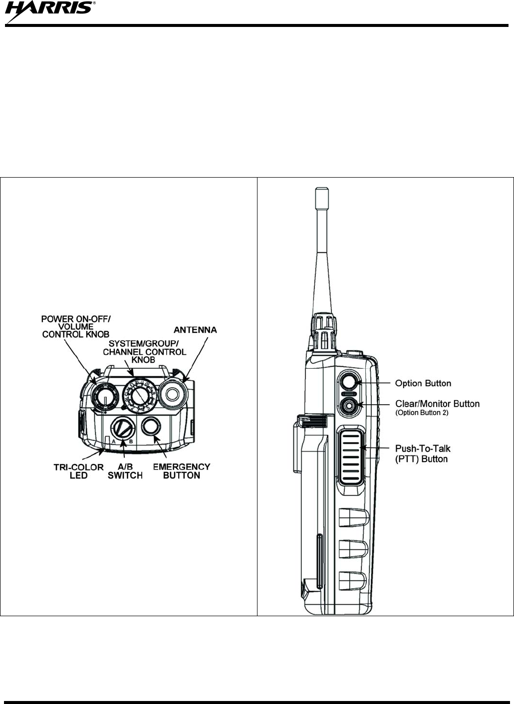
MM-013994-001, Rev. Ap1
95
10 CONVENTIONAL OPERATION
The radio functions in the conventional mode when using conventional communications channels (non-
trunked).
10.1 CONTROLS
The radio features two rotary control knobs and an emergency button mounted on the top of the radio.
Push-To-Talk and option buttons are mounted on the side. The front mounted keypad has six buttons on
the P7350 Scan model and 15 buttons on the P7370 System model.
Figure 10-1: Top View Figure 10-2: Side View

MM-013994-001, Rev. Ap1
96
10.1.1 Buttons and Knobs
This section describes the primary function of the button and knob controls. Refer to Figure 10-1 and
Figure 10-2.
POWER ON/OFF-VOLUME
CONTROL KNOB Applies power to and adjusts the receiver’s volume. Rotating the
control clockwise applies power to the radio. A single alert tone (if
enabled through programming) indicates the radio is operational.
Rotating the control clockwise increases the volume level. Minimum
volume levels may be programmed into the radio to prevent missed
calls due to a low volume setting. While adjusting the volume the
display will momentarily indicate the volume level (i.e. VOL=31).
The volume range is from a minimum programmed level of zero
(displayed as OFF in the display) up to 40, which is the loudest level.
SYSTEM/GROUP/CHANNEL
CONTROL KNOB Selects pre-programmed channels. This is a 16-position rotary knob.
Note: A mechanical stop, which can limit the positions accessed, is
shipped with the radio but must be installed. To install the mechanical
stop, remove the System/Group/Channel control knob, loosen the set
screw on the System/Group/Channel control knob metal base (using a
1.27mm hex wrench), and remove the System/Group/Channel control
knob metal base. Replace the 16 channel ring with the channel stop
ring located at the desired channel. Re-install the
System/Group/Channel control knob metal base, tighten the set screw,
and re-install the System/Group/Channel control knob.
EMERGENCY/HOME BUTTON Automatically selects the pre-programmed Group/System by pressing
and holding for a programmed duration. It can also be used to declare
an emergency by pressing and holding for a programmed duration.
The button must be pre-programmed for either operation, but not both.
PTT BUTTON PTT must be pressed before voice transmission begins.
OPTION BUTTON Activates one of a number of programmable software options selected
during PC programming. Programmable options include hi/low power
settings, keypad lock, LCD contrast, and LCD and keypad back
lighting.
CLEAR/MONITOR BUTTON
(OPTION BUTTON 2) Unsquelches the receiver and allows channel monitoring prior to
transmission. Momentarily removes the Receiver Channel Guard
decoding from the channel.
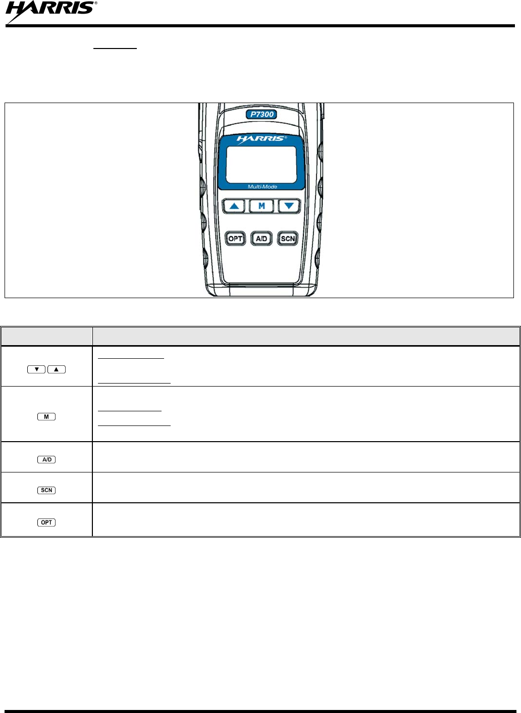
MM-013994-001, Rev. Ap1
97
10.1.2 Keypad
The keys on the keypad have special functions and are labeled using a symbol or abbreviated word
describing its primary function. Numeric entry is a secondary function of the keys. Each key is described
in the following subsections.
Figure 10-3: P7350 “Scan” Radio Front Panel
KEY FUNCTION
Primary Function: Allows the user to scroll through available systems, groups, or channels, depending on
personality programming.
Secondary Function: Changes the selection for an item within a list.
Primary Function: Accesses the pre-stored menu.
Secondary Function: Activates a selected item within a list. This is similar to an “Enter” key.
Adds/Deletes selected groups or channels from the Scan list of the currently selected system.
Turns the Scan operation ON and OFF.
Activates one of a number of pre-programmed software options.
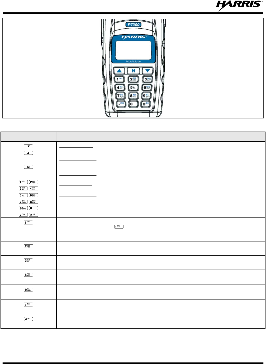
MM-013994-001, Rev. Ap1
98
Figure 10-4: P7370 “System” Radio Front Panel
KEY FUNCTION
Primary Function: Allows the user to scroll through available systems, groups, or channels, depending on
personality programming.
Secondary Function: Changes the selection for an item within a list.
Primary Function: Accesses the pre-stored menu.
Secondary Function: Activates a selected item within a list. This is similar to an “Enter” key.
Primary Function: Refer to the separate key definitions within this table.
Secondary Function: These keys function much as a typical DTMF telephone pad 0-9, *, and # keys; and are
used to place telephone interconnect calls and individual unit-to-unit calls.
Selects a specific system. If the rotary knob is programmed to select the system and more than 16 systems are
programmed in the radio, the key is used to select additional banks (groupings) of systems.
Selects a specific group.
Turns the Scan operation ON and OFF.
Adds groups or channels from the currently selected system to the Scan list.
Deletes selected groups or channels of the currently selected system from the Scan list.
Places telephone interconnect calls.
Initiates individual calls.
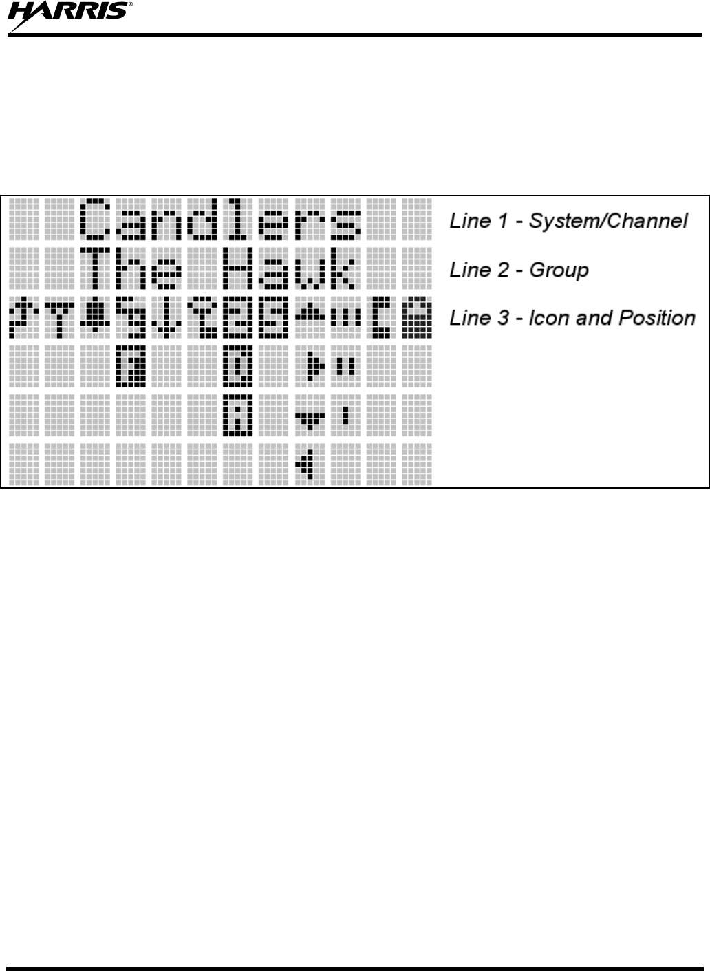
MM-013994-001, Rev. Ap1
99
10.2 DISPLAY
The radio display is made up of 3 lines (see Figure 10-5). Lines 1 and 2 contain eight alphanumeric
character blocks and are used primarily to display system or group/channel names. Line 1 also displays
radio status messages. The 3rd line is used primarily to display radio status icons. All three lines are used
to display menu options when in the menu mode. If programmed, the display backlighting will illuminate
upon power up or when radio controls are operated.
Figure 10-5: P7300 Radio Display
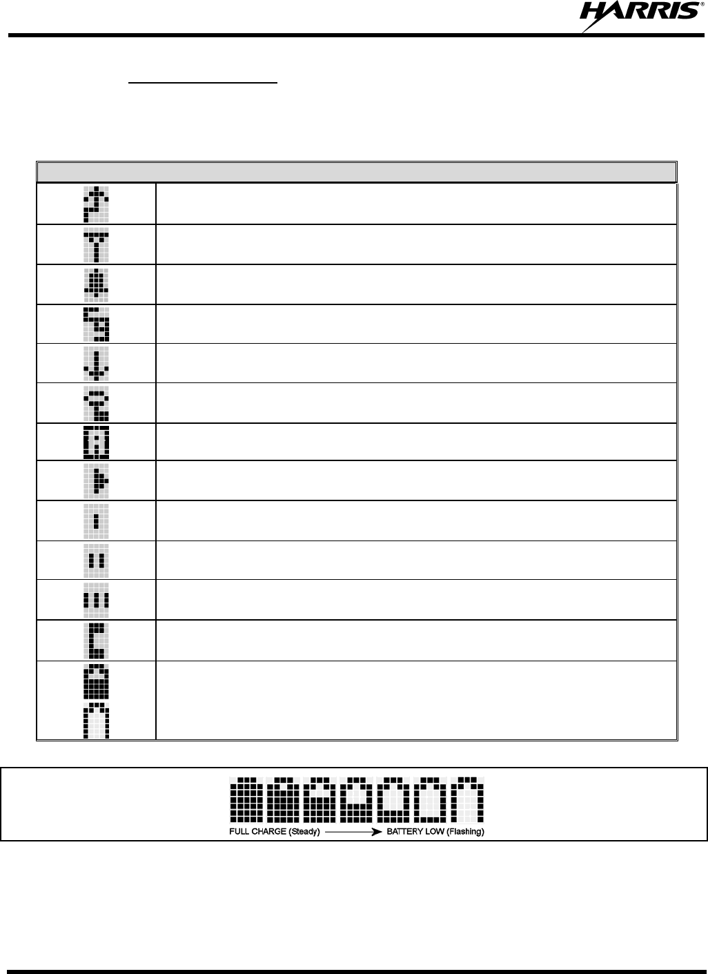
MM-013994-001, Rev. Ap1
100
10.2.1 Radio Status Icons
Status Icons indicate the various operating characteristics of the radio. The icons show operating modes
and conditions and appear on the third line of the display (see Table 10-1).
Table 10-1: Status Icon Descriptions
CONVENTIONAL STATUS ICONS
Steady – during all radio transmissions. Appears in the 1st position of the display.
Steady – “Busy” transmitting or receiving. Appears in the 2nd position of the display.
Flashing – call queued.
Steady – T99 Mode enabled. Appears in the 3rd position of the display.
Steady – Channel Guard enabled. Appears in the 4th position of the display.
If icon is not visible – Channel Guard is disabled.
Steady – transmit at low power. Appears in the 5th position of the display.
If icon is not visible – transmit at high power.
Steady – transmit in encrypt mode. Appears in the 6th position of the display.
Flashing – receiving an encrypted call.
Steady – Indicates the current channel is set up as an analog channel. Appears in the 7th position of
the display.
Animated (rotates clockwise) – scan mode enabled. Appears in the 9th position of the display.
If icon is not visible – scan is disabled.
Steady – priority 1 group or channel. Appears in the 10th position of the display.
Steady – priority 2 group or channel. Appears in the 10th position of the display.
Steady – group or channel in scan list. Appears in the 10th position of the display.
Steady – special call mode (individual or telephone). Appears in the 11th position of the display.
Steady – battery charge indicators. Appear in the 12th position of the display.
Flashing – Low battery indicator.
Figure 10-6: Battery Charge Icons (Full Cycle)
The battery icons (see Figure 10-6) indicate approximate level only, based on battery voltage.
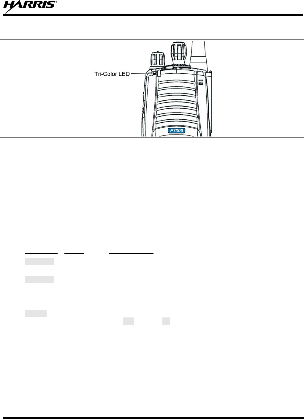
MM-013994-001, Rev. Ap1
101
10.3 TRI-COLOR LED
Figure 10-7: Tri-Color LED
The Tri-Color LED changes color to indicate radio status and is visible from both the front and top of the
radio (see Figure 10-7). The colors of the LED and the status they represent are:
Green: Receiving
Red: Transmitting Unencrypted
Orange: Transmitting Encrypted
10.4 STATUS MESSAGES
During radio operation, various radio Status Messages can be displayed. The messages are described
below.
MESSAGE NAME DESCRIPTION
TALKARND Talkaround Indicates the radio is operating on conventional channels in talkaround
mode (no repeater).
LOW BATT Low Battery Battery voltage has dropped to the point to where the radio is no longer
able to transmit. The radio will still receive calls until the battery is
discharged beyond the point of operation at which time the radio will
automatically shutdown.
VOL=31 Volume Level Indicates the current volume level. The volume level display ranges
from OFF (silent) to 40 (loudest).
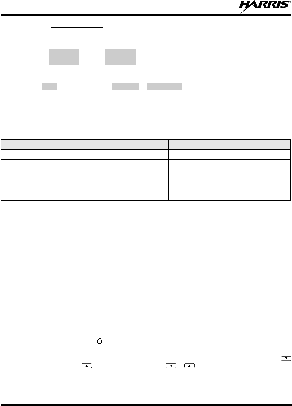
MM-013994-001, Rev. Ap1
102
10.4.1 Error Messages
If either of the Error Messages shown below is displayed, the radio is programmed incorrectly or needs
servicing.
DSP ERR
ERR=XXXX
(PowerUp
only)
or DIG V x
ERR x
Where: xxxx is the error code and DSP ERR or DIG V ERR is the message.
10.5 ALERT TONES
The P7300 radio provides audible Alert Tones or “beeps” to indicate the various operating conditions (see
Table 10-2).
Table 10-2: Alert Tones
NAME TONE DESCRIPTION
Call Originate one short mid-pitched OK to talk after pressing the push-to-talk button
Carrier Control Timer five high-pitched/one long low-pitched PTT depressed for maximum length of time
Low Battery one low-pitched/one short mid-pitched Low battery
TX Low Battery Alert one low-pitched After PTT - battery too low to transmit
10.6 TURNING ON THE RADIO
1. Power ON the radio by rotating the POWER ON-OFF/VOLUME knob clockwise. A short alert
signal (if enabled through programming) indicates the radio is ready to use.
2. The display shows the last selected system and group/channel or a default system and group/channel
(depending on programming).
3. Adjust the POWER ON-OFF/VOLUME knob to the desired volume level.
4. Select the desired system, group/channel. The display indicates the current system and group/channel
names.
5. The radio is now ready to transmit and receive calls.
10.7 SYSTEM SELECTION
METHOD 1: From the control knob: If system selection is programmed to the
System/Group/Channel control knob, select a system
b
y turning the knob to the
desired number position (1-16). The display registers the new system name on line
one. The button can be programmed to provide access to a “2nd bank” of 16 system
number positions (17-32).
METHOD 2: From the keypad: If system selection is programmed as the primary function of
and , select a system by pressing or to scroll through the system list. The
display registers the new system name on line one.
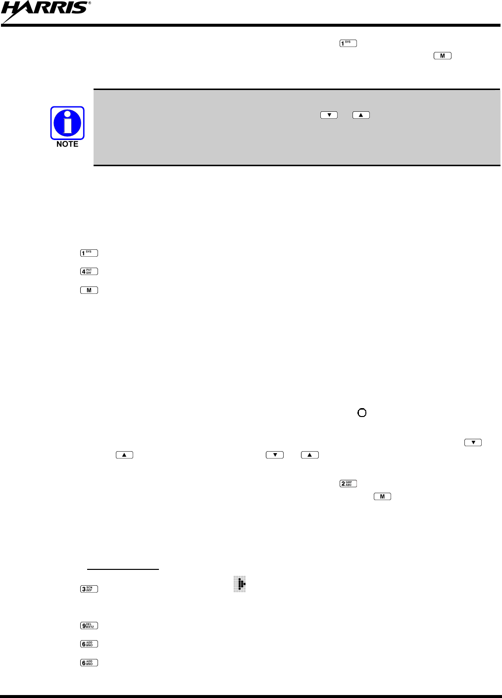
MM-013994-001, Rev. Ap1
103
METHOD 3: (P7370 model radios only) Direct Access: Press to enter the system select mode.
Press the numeric key, which is mapped to the desired system. Press . The radio
will move to the selected system.
If system selection is programmed to the System/Group/Channel control knob, direct
access to systems will not be available. Pressing or will scroll through different
sets of 16 systems each (banks) if more than 16 systems are programmed into the radio.
The systems within each bank are then selectable via the System/Group/Channel control
knob as described previously in METHOD 1.
Example:
System: 1 = North Group: 1 = Group 1
2 = South 2 = Group 2
3 = East 3 = Group 3
4 = West 4 = Group 4
1. Press . (South is the currently selected system.)
2. Press . (Press 4 to select the “West” system.)
3. Press . (West is the newly selected system.)
10.8 GROUP/CHANNEL SELECTION
Several methods can be used to select a new group/channel.
METHOD 1: From the Control knob: If group selection is programmed to the System/Group/Channel
control knob, select a group by turning the System/Group/Channel control knob to the
desired group number position. The display registers the new group name on line two.
If the knob is moved to a position greater than the number of programmed group, the
highest programmed group will remain selected. The
b
utton can be programmed to
provide access to a “2nd bank” of 16 group number positions (17-32)
METHOD 2: From the keypad: If group selection is programmed as the primary function of and
, select a group by pressing or to scroll through the list. The display
registers the new group name on line two.
METHOD 3: (P7370 model radios only) Direct Access: Press to enter the group select mode.
Press the numeric key mapped to the desired group. Press . The radio will move to
the selected group.
10.9 MODIFY SCAN LIST
10.9.1 P7370 Model
1. Press to toggle scan OFF and verify is not displayed.
2. Select group or channel.
3. Press once to remove group or channel from list.
4. Press once to add as a normal group or channel.
5. Press twice to add as a Priority 2 group or channel.
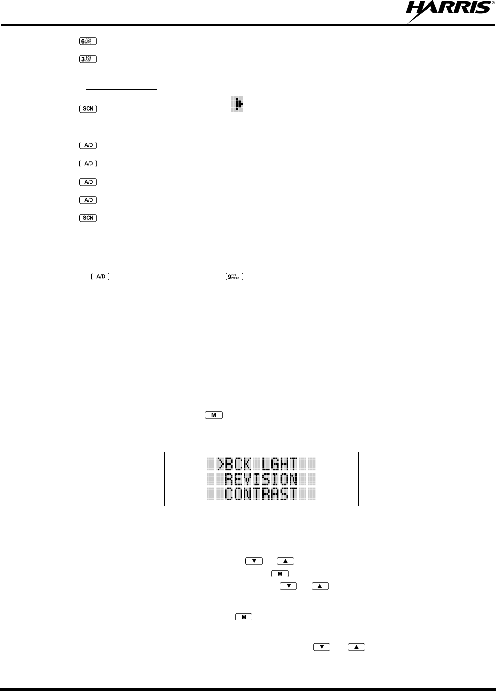
MM-013994-001, Rev. Ap1
104
6. Press three times to add as a Priority 1 group or channel.
7. Press to re-start scanning.
10.9.2 P7350 Model
1. Press to toggle scan OFF and verify is not displayed.
2. Select group or channel.
3. Press once to remove group or channel from the list.
4. Press once to add as a normal group or channel.
5. Press twice to add as a Priority 2 group or channel.
6. Press three times to add as a Priority 1 group or channel.
7. Press to re-start scanning.
10.10 NUISANCE DELETE
A channel can temporarily be deleted from the scan list, if it is not the currently selected channel, by
pressing the key (P7350 model) or the key (P7370 model) during scan operation while the radio
is displaying the unwanted channel. The channel will be deleted from the scan list in the same manner as
if done using the steps above. Deletions done in this manner will not remain deleted if the radio is
powered OFF and then powered ON.
10.11 MENU
The Menu function accesses features that are not available directly from the keypad. The order and actual
menu items available is configurable through programming. At radio power up, the menu item that is at
the top of the menu list will always be displayed first. Subsequent access to the menu function will return
the last menu item that was shown in the display and cursor position.
1. To enter the menu mode, press the key.
2. Upon entering the menu selection mode, Menu options will appear in the display (see Figure 10-8).
Figure 10-8: Menu Display
3. The radio will continue to receive and transmit normally while in the menu function.
4. To scroll through the menu options use the or keys. When the required menu item has been
found align the cursor with the option then press to select it. The menu item's parameter setting
shown in the display can now be changed by using or to scroll through the list of parameter
values.
5. Once the desired setting is reached press to store the value and return the menu option selection
level.
6. For menu items that display radio information, pressing or will scroll through a list of
informational displays. Possible menu items are listed in Table 10-3.
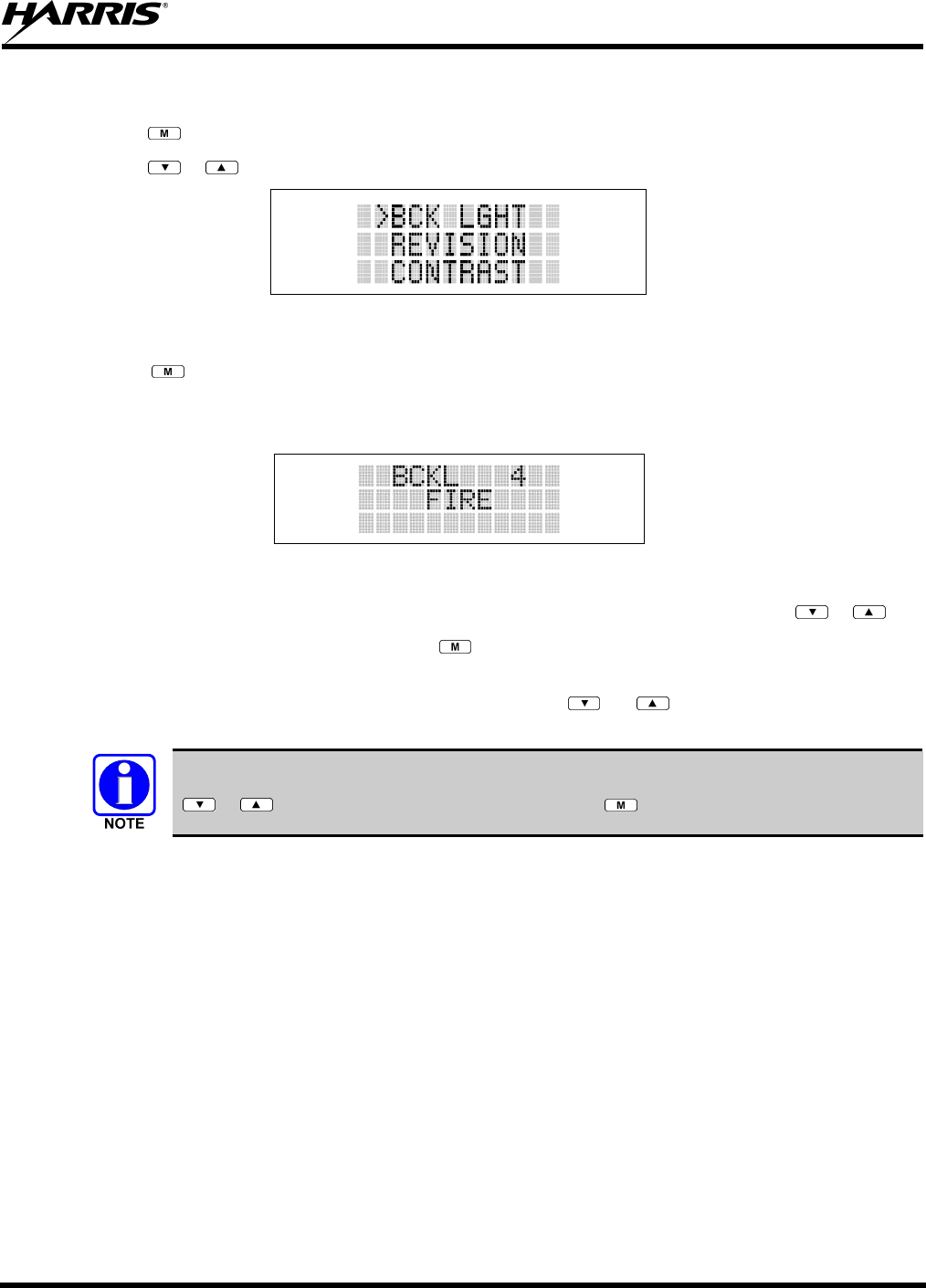
MM-013994-001, Rev. Ap1
105
An example of the backlight menu item selection process and menu item parameter change is shown in
Figure 10-9.
1. Press to enter the menu mode.
2. Press or until the display shows:
Figure 10-9: Backlight Menu Item Parameter
3. Press . The backlight menu item is activated. Line one shows the active menu item and its
current parameter setting. Line two shows the currently selected system or group name (see Figure
10-10).
Figure 10-10: Backlight Menu Display
4. The menu item's parameter setting shown in the display can now be changed by using or .
5. Once the desired setting is reached press to store the value and return the menu option selection
level.
For menu items that display radio information, pressing or will scroll through a list of
informational displays. An example of information displays is shown in Table 10-4.
The TX POWER menu item, when selected, toggles LOW/HIGH power. It does not use
or to scroll nor is an additional press of the button required.

MM-013994-001, Rev. Ap1
106
Table 10-3: Menu Item Information
FEATURE DISPLAY PARAMETER
SETTING COMMENT
Keypad Lock Menu Item:
KEY LOCK
Once Selected:
LOCKED
Locked
Unlocked
Locks the keypad. To unlock; press and release then within 1
second press the option button (NOTE: this sequence is also a short cut
to locking the keypad.)
Backlight Adjust Menu Item:
BCK LIGHT
Once Selected:
BCKL=
OFF, 1 thru 6 Selects the light level for backlighting.
Contrast Adjust Menu Item:
CONTRAST
Once Selected:
CNTRST=
1, 2, 3, 4 Selects the display contrast level.
Transmit Power Select Menu Item:
TX POWER
Once Selected:
POWER=
HIGH or LOW Selects radio output power mode.
Radio Revision
Information
Menu Item:
REVISION
N/A Selects the information display to view. Informational display only (see
Table 10-4). No user selectable settings.
Toggle Scan On/Off SCAN ON/OFF Toggles Scan operation ON/OFF.
Display Current Home
Group/Channel
HOME N/A Selects Home Group/Channel
Select Desired System SYS SEL N/A Selects a new system.
Add Group/Channel to
Scan List
SCAN ADD N/A Adds to Scan List.
Delete Group/Channel SCAN DEL N/A Deletes Group or Channel from Scan List.
Add/Delete Scan List SCAN A/D N/A Add or Delete from Scan List.
Talkaround TALKARND ON/OFF Toggles Talkaround feature ON/OFF.
Select Channel CHN SEL N/A Conventional Only.
Feature Encryption
Display
Menu Item:
FEATURES
Once Selected:
(See Feature
Encryption Display
Section)
N/A Indicates current features programmed into the radio as well as certain
information required to add features to the radio. Informational display
only. No user selectable settings.

MM-013994-001, Rev. Ap1
107
Table 10-4: Information Display
RADIO ID
XXXXXXXX
LID in EDACS/EA. In CONV it has no
meaning.
RAM SIZ RAM Size
FLSH SIZ Flash Size
RF BAND Frequency Band
PERS VER Software Version
DSP DATE Date DSP code was built.
DSP TIME Time DSP code was built.
DSP FEAT The DSP Features supported by the
DSP code, in Hexadecimal.
Bit mapped (see IPC spec for details):
• 0x0001 – Conventional
• 0x0002 – EDACS
• 0x0010 – AMPF
• 0x0020 – undefined
DSP VER DSP Software Version
FLSH VER FLASH Software
ex: P73U0102
P=portable, 54=5400 radio,
U=unencrypted, 01=major revision (>50
means unreleased code), 02=minor
revision
HARRIS
(C) 2009
Copyright
PERSNLTY Personality Name
BLD DATE Date host (ARM) code was built.
BLD TIME Time host (ARM) code was built.
10.12 BACKLIGHT ADJUST
1. Press to access the menu.
2. Press or to scroll through menu until “BCKLGHT” appears.
3. Press to select Backlight menu.
4. Press or to scroll through available settings OFF, 1 through 6.
5. Press to select new backlight setting.
10.13 CONTRAST ADJUST
1. Press to access the menu.
2. Press or to scroll through menu until “CONTRAST” appears.
3. Press to select Contrast menu.
4. Press or to adjust contrast setting from 1 - 4.
5. Press to select new contrast setting.
10.14 DECLARING AN EMERGENCY
1. Press and hold the red Emergency/Home button (the length of time is programmable; check with the
system administrator).
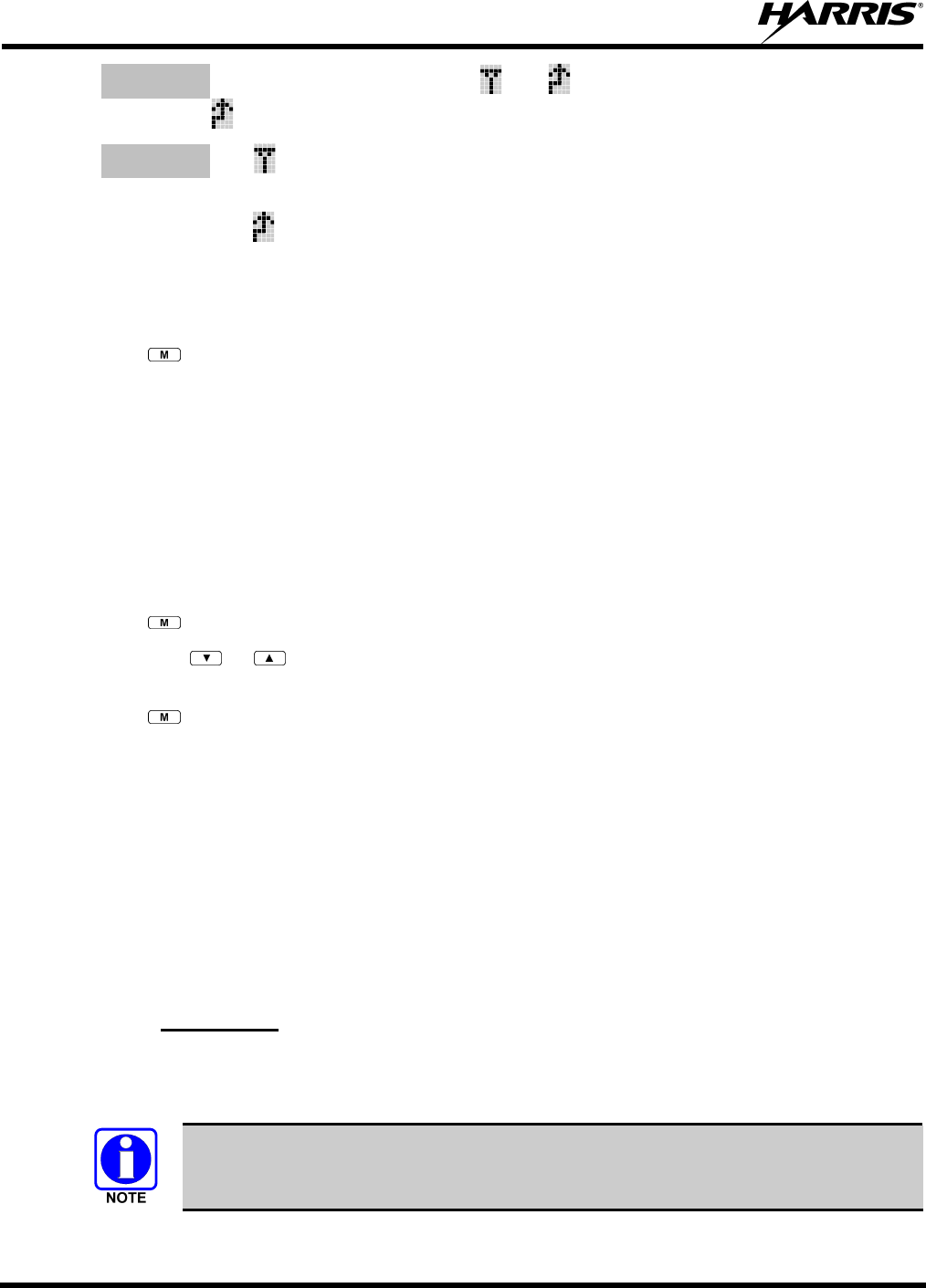
MM-013994-001, Rev. Ap1
108
2. *TXEMER* will flash in the display, plus and will be displayed. After 2-3 seconds the
transmit icon will turn off.
3. *TXEMER* and will remain until the emergency is cleared. (Refer to Section 8.21 for more
detail concerning emergency operation.)
4. Press the PTT and will reappear.
5. Release PTT when the transmission is complete.
10.15 LOCKING/UNLOCKING KEYPAD
1. Press button.
2. Within 1 second, press the Option button on the side of the radio.
10.16 HIGH/LOW POWER ADJUSTMENT
Transmit power adjustment is possible if enabled through programming. Within conventional systems,
transmit power is adjustable on a per channel basis. Within EDACS trunking systems, transmit power is
adjustable on a per system basis.
There are two ways to toggle between high and low power:
Using the Menu Button:
1. Press .
2. Using the or key, scroll until the cursor (>) appears to the left of “TX POWER” in the
display.
3. Press again to toggle between High and Low power.
4. “POWER = HIGH” or “POWER = LOW” will appear momentarily on the top line of the display.
Using the Pre-Programmed Option Button:
Press the Option button. “POWER = HIGH” or “POWER = LOW” will appear momentarily on the top
line of the display.
10.17 DIGITAL VOICE OPERATION
Digital voice programmed systems have three (3) different voice modes: clear (analog), digital, and
private (encrypted). The voice modes are programmed on a per-group basis within each trunked system
and on a per-channel basis within each conventional system.
10.17.1 Clear Mode
The Clear Mode is a voice mode in which the radio transmits and receives only clear (analog) voice
signals. These analog signals are non-digitized. Clear mode transmissions can be monitored easily by
unauthorized persons.
Groups or channels programmed for clear operation cannot transmit or receive digital
messages.
MM-013994-001, Rev. Ap1
109
10.17.2 Digital Mode
The Digital Mode allows the radio to transmit and receive digitized voice signals. Digital signals provide
improved weak signal performance and cannot be easily monitored with a standard receiver. Groups and
channels programmed for digital operation transmit only digital signals. Individual phone calls (I-Calls)
are answered back in the mode in which they were received assuming the call or hang time is still active.
Individual phone, all call, and emergency calls are transmitted clear if the digital mode is disabled or
inoperative.
1. If receiving an analog message trunked call, the radio responds in the analog mode during the
hang time on the working channel.
2. If receiving an analog I-Call, the radio responds in the analog mode during the hang time.
3. When using the *WHC* feature to respond to an I-Call (after the hang time has expired), the call
is transmitted in the mode defined by the system mode as programmed for the current system if
the ID being called is not in the I-Call list. If the ID is in the I-Call list, then the call is transmitted
as defined by the I-Call mode programmed in the list for that ID.
The overdial DTMF tones are not available while in the Digital Mode.
10.17.2.1 Scanned Group Calls
Receiving a Scanned Group Call is the same as receiving a selected group call. During the scan hang
time, if the radio was programmed for auto-select, it will transmit back in the same mode it received the
call. For example, if a clear group is entered in the scan list, it will only receive clear calls. If the same
group was available in digital and entered in the scan list, it can receive clear and digital calls, provided
auto-select was programmed in the radio. The user can choose to transmit on the scanned or selected
group. If a group is entered in the scan list more than once under different modes (clear and digital), only
the first occurrence of the group will be used.
Table 10-5: Transmit/Receive Mode Compatibility for Digital Voice Operation
GROUP/CHANNEL PROGRAMMING
(TRANSMIT) CLEAR
RECEIVE DIGITAL
RECEIVE
CLEAR Yes No
DIGITAL Yes Yes
Conventional digital channels require Channel Guard on the channel to operate
correctly.
The voice coding technology embodied in this product is protected by intellectual
property rights including patent rights, copyrights, and trade secrets of Digital Voice
Systems, Inc. The user of this technology is explicitly prohibited from attempting to
decompile, reverse engineer, or disassemble the Object Code, or in any other way
convert the Object Code into human-readable form.
10.18 RECEIVING A CALL
1. Select the desired conventional system/channel or turn scan ON and make sure desired channel is in
scan list.

MM-013994-001, Rev. Ap1
110
2. When the radio receives a call, the radio will unmute and the channel name will appear in the display.
10.19 SENDING A CALL
1. Select desired system/channel.
2. Ensure the channel is not busy by pressing the button momentarily. If audio is heard or if the
icon is on, the channel is busy.
3. When you’re sure that the channel is not busy, press the PTT button and speak into the microphone.

MM-013994-001, Rev. Ap1
111
This page intentionally left blank

MM-013994-001, Rev. Ap1
112
P25 OPERATION
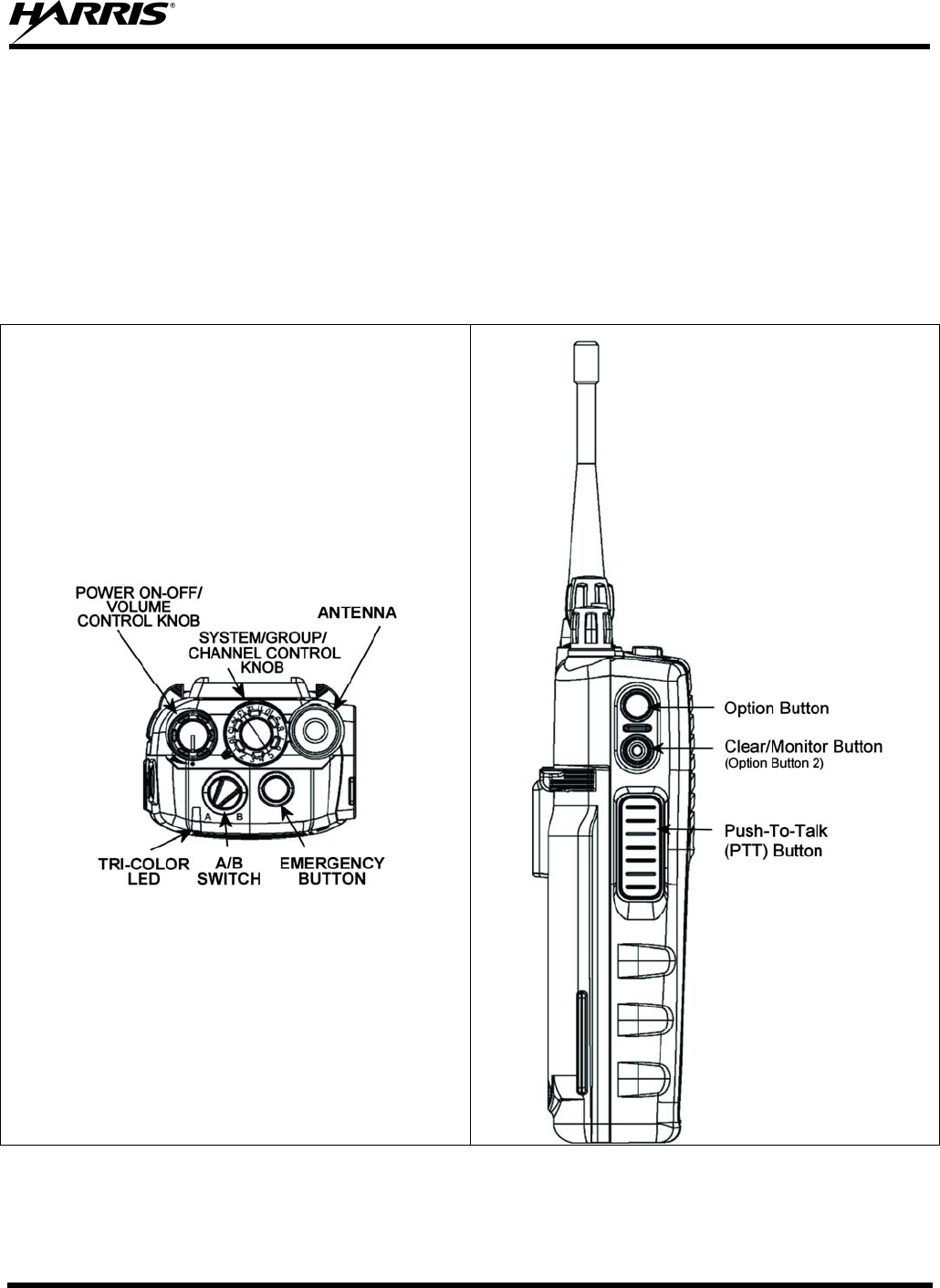
MM-013994-001, Rev. Ap1
113
11 P25 OPERATION
Once a P25 system has been selected from the available systems on your P7300 series portable radio, the
characteristics described in the following sections will govern operation.
11.1 CONTROLS
The radio features two rotary control knobs and an emergency button mounted on the top of the radio.
Push-To-Talk and option buttons are mounted on the side. The front mounted keypad has six buttons on
the P7350 Scan model and 15 buttons on the P7370 System Radio.
Figure 11-1: Top View Figure 11-2: Side View

MM-013994-001, Rev. Ap1
114
11.1.1 Buttons and Knobs
This section describes the primary function of the button and knob controls. Refer to Figure 11-1 and
Figure 11-2.
POWER ON/OFF-VOLUME
CONTROL KNOB Applies power to and adjusts the receiver’s volume. Rotating the
control clockwise applies power to the radio. A single alert tone (if
enabled through programming) indicates the radio is operational.
Rotating the control clockwise increases the volume level. Minimum
volume levels may be programmed into the radio to prevent missed
calls due to a low volume setting. While adjusting the volume the
display will momentarily indicate the volume level (i.e. VOL=31). The
volume range is from a minimum programmed level of zero (displayed
as OFF in the display) up to 40, which is the loudest level.
SYSTEM/GROUP/CHANNEL
CONTROL KNOB Selects systems or groups/channels (depending on programming). This
is a 16-position rotary knob.
Note: A mechanical stop, which can limit the positions accessed, is
shipped with the radio but must be installed. To install the mechanical
stop, remove the System/Group/Channel control knob, loosen the set
screw on the System/Group/Channel control knob metal base (using a
1.27 mm hex wrench), and remove the System/Group/Channel control
knob metal base. Replace the 16 channel ring with the channel stop
ring located at the desired channel. Reinstall the
System/Group/Channel control knob metal base, tighten the set screw,
and reinstall the System/Group/Channel control knob.
EMERGENCY/HOME BUTTON Automatically selects the pre-programmed Group/System by pressing
and holding for a programmed duration. It can also be used to declare
an emergency by pressing and holding for a programmed duration. The
button must be pre-programmed for either operation, but not both.
PTT BUTTON Push-To-Talk must be pressed before voice transmission begins. In
trunked mode the radio’s ID is transmitted upon depression of the PTT
button.
OPTION BUTTON Activates one of a number of programmable software options selected
during PC programming. Programmable options include hi/low power
settings, keypad lock, LCD contrast, and LCD and keypad back
lighting.
CLEAR/MONITOR BUTTON
(OPTION BUTTON 2) Unsquelches the receiver and allows channel monitoring prior to
transmission. Momentarily removes the Receiver Channel Guard
decoding from the channel.
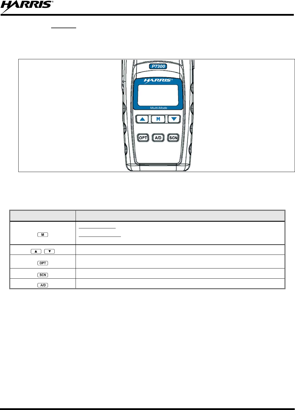
MM-013994-001, Rev. Ap1
115
11.1.2 Keypad
The keys on the keypad have special functions and are labeled using a symbol or abbreviated word
describing its primary function. Alpha-numeric entry is a secondary function of the keys. Each key is
described in the following subsections.
Figure 11-3: P7350 “Scan” Radio Front Panel
Table 11-1: P7350 Keypad Functions
KEY FUNCTION
Primary Function: Accesses the pre-stored menu.
Secondary Function: Activates a selected item within the menu. This is similar to an “Enter”
key.
Scrolls thru available menu items.
Activates one of any programmable software options selected during the PC programming,
including: high/low TX power and talkaround.
Toggles SCAN operation ON and OFF.
Adds/Deletes selected groups or channels from SCAN list of the currently selected system.
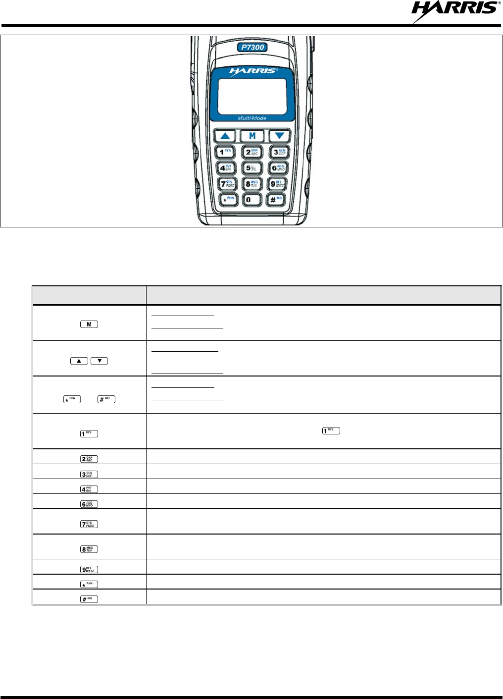
MM-013994-001, Rev. Ap1
116
Figure 11-4: P7370 “System” Radio Front Panel
Table 11-2: P7370 “System” Keypad Functions
KEY FUNCTION
Primary Function: Accesses the pre-stored menu.
Secondary Function: Activates a selected item within the menu. This is similar to an “Enter”
key.
Primary Function: Allows the user to scroll through available systems, groups, or channels,
depending on personality programming.
Secondary Function: Changes the selection for an item within a list.
0-9,
and
Primary Function: Refer to the separate key definitions within this table.
Secondary Function: These keys function much as a typical DTMF telephone pad 0-9, *, and #
keys; and are used to place telephone interconnect and individual (unit-to-unit) calls.
Selects a specific system. If the rotary knob is used to select the system and more than 16
systems are programmed in the radio, the key is used to select additional banks
(groupings) of systems.
Selects a specific group.
Turns the Scan operation ON and OFF.
Enables or disables Private Mode for the system/group/channel displayed.
Adds groups or channels from the currently selected system to the Scan list.
Status. Access to the status list (0-9). The Status key permits the transmission of a pre-
programmed status message to an EDACS site.
Message. Access to the message list (0-9). The Message key permits the transmission of a pre-
programmed message to an EDACS site.
Deletes selected groups or channels of the currently selected system from the Scan list.
Initiates telephone interconnect calls.
Initiates individual unit-to-unit calls.
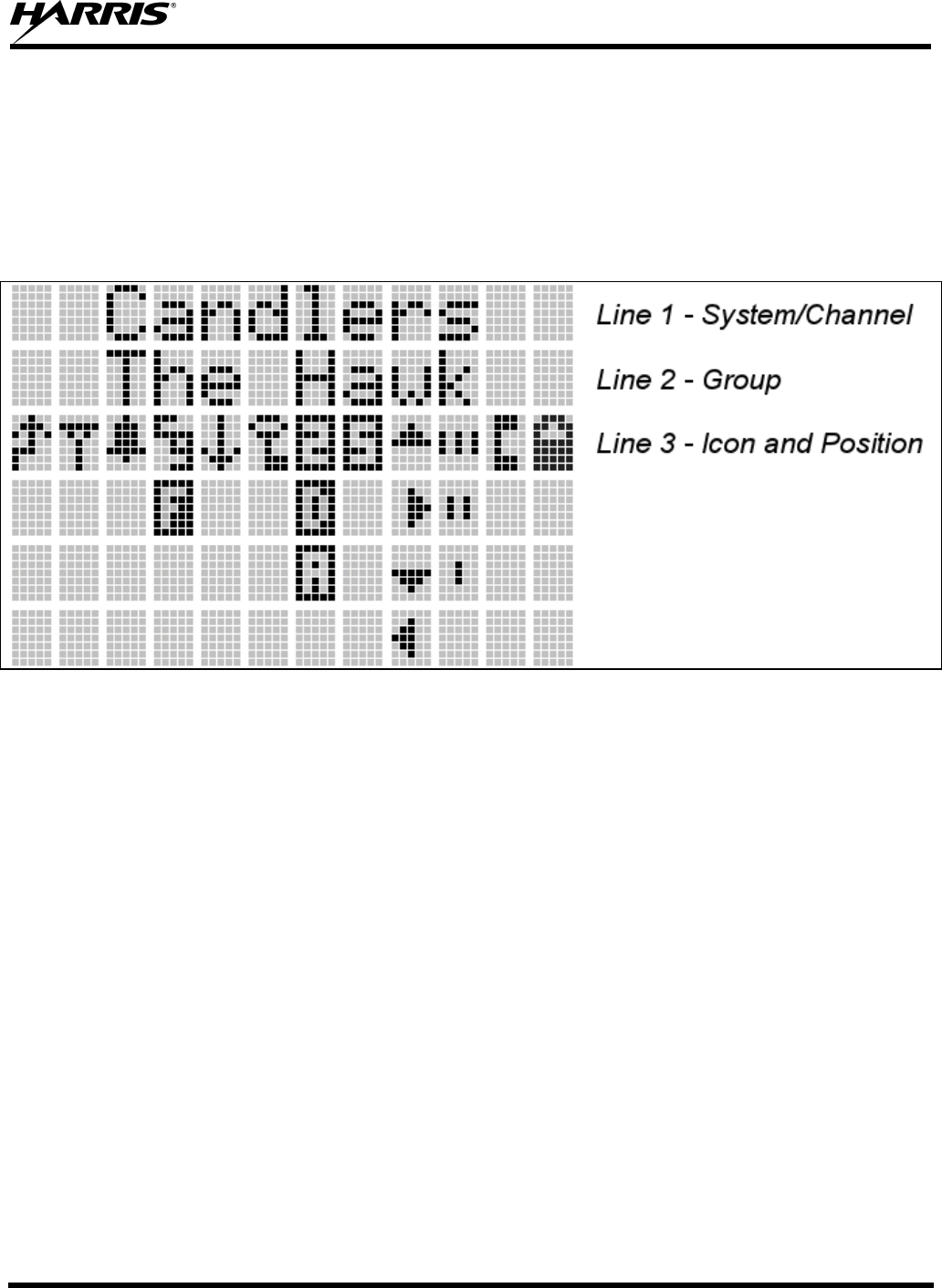
MM-013994-001, Rev. Ap1
117
11.2 DISPLAY
The radio display is made up of 3 lines (see Figure 11-5). Lines 1 and 2 contain eight alphanumeric
character blocks and are used primarily to display system and group names. Line 1 also displays radio
status messages. The 3rd line is used primarily to display radio status icons. All three lines are used to
display menu options when in the menu mode. If programmed, the display backlighting will illuminate
upon power up or when radio controls are operated.
Figure 11-5: P7300 Radio Display
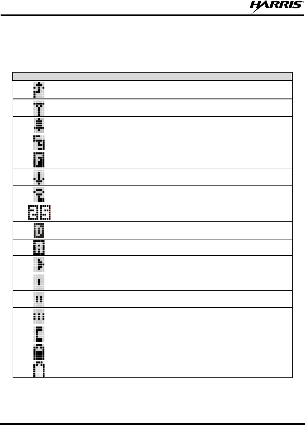
MM-013994-001, Rev. Ap1
118
11.3 RADIO STATUS ICONS
Status Icons indicate the various operating characteristics of the radio. The icons show operating modes
and conditions and appear on the third line of the display (see Table 11-3).
Table 11-3: Radio Status Icon Descriptions
EDACS, CONVENTIONAL, AND P25 ICONS
Steady – during all radio transmissions. Appears in the 1st position of the display.
Steady – “Busy” transmitting or receiving. Appears in the 2nd position of the display.
Flashing – call queued.
Steady – T99 Mode enabled. Appears in the 3rd position of the display.
Steady – Channel Guard enabled. Appears in the 4th position of the display.
If icon is not visible – Channel Guard is disabled.
Steady – trunked system in Failsoft™ mode. Appears in the 4th position of the display.
Steady – transmit at low power. Appears in the 5th position of the display.
If icon is not visible – transmit at high power.
Steady – transmit in encrypt mode. Appears in the 6th position of the display.
Flashing – receiving an encrypted call.
Steady – Indicates the current channel is set up as a Project 25 (P25) channel. Appears in the 7th (and
8th) positions of the display.
Steady – Indicates the current channel is set up as a ProVoice channel. Appears in the 7th position of
the display.
Steady – Indicates the current channel is set up as an analog channel. Appears in the 7th position of
the display.
Animated (rotates clockwise) – scan mode enabled. Appears in the 9th position of the display.
If icon is not visible – scan is disabled.
Steady – priority 1 group or channel. Appears in the 10th position of the display.
Steady – priority 2 group or channel. Appears in the 10th position of the display.
Steady – group or channel in scan list. Appears in the 10th position of the display.
Steady – special call mode (individual or telephone). Appears in the 11th position of the display.
Steady – battery charge indicators. Appear in the 12th position of the display.
Flashing – Low battery indicator.
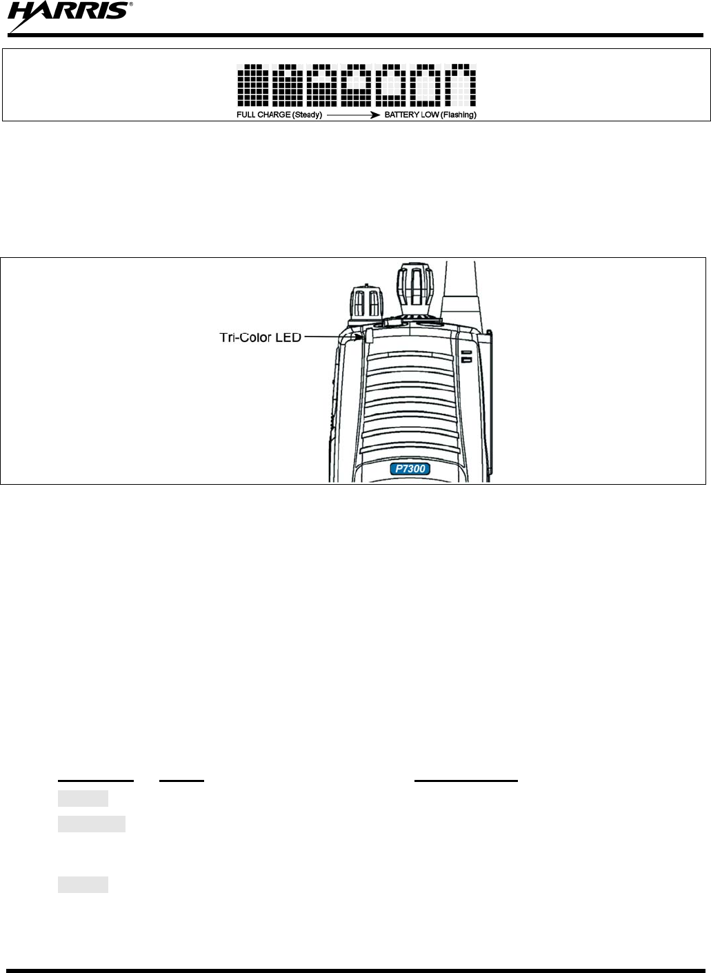
MM-013994-001, Rev. Ap1
119
Figure 11-6: Full Cycle Battery Charge Indicator
The battery charge indicators illustrate approximate level only, based on battery voltage. Refer to Figure
11-6.
11.4 TRI-COLOR LED
Figure 11-7: Tri-Color LED
The Tri-Color LED changes color to indicate radio status and is visible from both the front and top of the
radio (see Figure 11-7). The colors of the LED and the status they represent while operating in EDACS
and P25 modes are defined below.
Green: Receiving
Red: Unencrypted transmission
Orange: Encrypted transmission
11.5 STATUS MESSAGES
During radio operation, various radio Status Messages can be displayed. The messages are described
below.
MESSAGE NAME DESCRIPTION
QUEUED Call Queued Indicates the system has placed the call in a request queue.
SYS BUSY System Busy Indicates the system is busy, no channels are currently available, the queue
is full, or an individual call is being attempted to a radio that is currently
transmitting.
DENIED Call Denied Indicates the radio or talkgroup is not authorized to operate on the selected
system and/or talkgroup.

MM-013994-001, Rev. Ap1
120
MESSAGE NAME DESCRIPTION
CC SCAN Control
Channel Scan Indicates the control channel is lost and the radio has entered the Control
Channel Scan mode to search for the control channel (usually out of range
indication).
WA SCAN Wide Area
Scan Indicates the radio has entered the Wide Area Scan mode to search for a
new system (if enabled through programming).
SYSC ON System Scan
Features On Indicates the System Scan features are enabled.
SYSC OFF System Scan
Features Off Indicates the System Scan features are disabled.
LOW BATT Low Battery Battery voltage has dropped to the point to where the radio is no longer able
to transmit. The radio will still receive calls until the battery is discharged
beyond the point of operation at which time the radio automatically shuts
down.
RXEMER Receive
Emergency Indicates an emergency call is being received. This message will be
flashing on line two.
TXEMER Transmit
Emergency Indicates an emergency call has been transmitted on this radio. This
message will be flashing on line two.
VOL=31 Volume Level Indicates the current volume level. The volume level display ranges from
OFF (silent) to 40 (loudest).
WHC Who Has
Called Indicates an individual call has been received, but not responded to. The
indicator turns OFF if the individual call mode is entered, the system is
changed, or the radio is turned off and then on again.
UNKNOWN Unknown ID Indicates an individual call is being received from an unknown ID.
11.5.1 Error Messages
If either of the Error Messages shown below is displayed, the radio is programmed incorrectly or needs
servicing.
DSP ERR
ERR=XXXX
(PowerUp
only)
or DIG V x
ERR x
Where: xxxx is the error code and DSP ERR or DIG V ERR is the message.
MM-013994-001, Rev. Ap1
121
11.6 ALERT TONES
The P7300 series radios provide audible Alert Tones or “beeps” to indicate the various operating
conditions (see Table 11-4).
Table 11-4: Alert Tones
NAME TONE DESCRIPTION
Call Originate one short mid-pitched OK to talk after pressing the push-to-talk button
Call Queued one high-pitched Call queued for processing
Autokey one mid-pitched Queued call received channel assignment
System Busy three low-pitched System busy or unable to complete call
Call Denied one low-pitched Radio is not authorized on the system or group
Carrier Control Timer five high-pitched/one long low-pitched PTT depressed for maximum length of time
Low Battery one low-pitched/one short mid-pitched Low battery
TX Low Battery Alert one low-pitched After PTT - battery too low to transmit
11.7 TURNING ON THE RADIO
1. Power ON the radio by rotating the POWER ON-OFF/VOLUME knob clockwise. A short alert
signal (if enabled through programming) indicates the radio is ready to use.
2. The display shows the last selected system and group or a default system and group (depending on
programming).
3. Adjust the POWER ON-OFF/VOLUME knob to the desired volume level.
4. Select the desired system and group. The display indicates the current system and group names.
5. The radio is now ready to transmit and receive calls.
11.8 SYSTEM SELECTION
METHOD 1: From the Control knob: If system selection is programmed to the
System/Group/Channel control knob, select a system by turning the knob to
the desired system number position (1-16). The display registers the new
system name on line one. The button can be programmed to provide
access to a “2nd bank” of 16 system number positions (17-32).
METHOD 2: From the keypad: If system selection is programmed as the primary function
of and select a system by pressing or to scroll through the
system list. The display registers the new system name on line one.
METHOD 3: (P7370 model radios only) Direct Access: Press to enter the system
select mode. Press the numeric key, which is mapped to the desired system.
Press . The radio will move to the selected system.
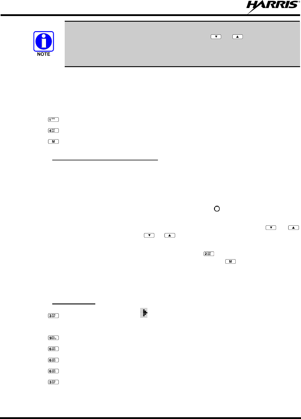
MM-013994-001, Rev. Ap1
122
If system selection is programmed to the System/Group/Channel control knob, direct
access to systems will not be available. Pressing or will scroll through
different sets of 16 systems each (banks) if more than 16 systems are programmed into
the radio. The systems within each bank are then selectable via the
System/Group/Channel control knob as described previously in METHOD 1.
Example:
System: 1 = North Group: 1 = Group 1
2 = South 2 = Group 2
3 = East 3 = Group 3
4 = West 4 = Group 4
1. Press . (South is the currently selected system.)
2. Press . (Press 4 to select “West” system.)
3. Press . (West is the newly selected system.)
11.8.1 GROUP/CHANNEL SELECTION
Several methods can be used to select a new group or channel.
METHOD 1: From the Control knob: If group selection is programmed to the System/Group/Channel
control knob, select a group by turning the System/Group/Channel control knob to the
desired group number position. The display registers the new group name on line two.
If the knob is moved to a position greater than the number of programmed groups, the
highest programmed group will remain selected. The button can be programmed to
provide access to a “2nd bank” of 16 group number positions (17-32).
METHOD 2: From keypad: If group selection is programmed as the primary function of and ,
select a group by pressing or to scroll through the group list. The display
registers the new group name on line two.
METHOD 3: (P7370 model radios only) Direct Access: Press to enter the group select mode.
Press the numeric key mapped to the desired group. Press . The radio will move to
the selected group.
11.9 MODIFY SCAN LIST
11.9.1 P7370 Model
1. Press to toggle scan OFF and verify is not displayed.
2. Select group or channel.
3. Press once to remove group from list.
4. Press once to add as a normal group.
5. Press twice to add as a Priority 2 group.
6. Press three times to add as a Priority 1 group.
7. Press to re-start scanning.
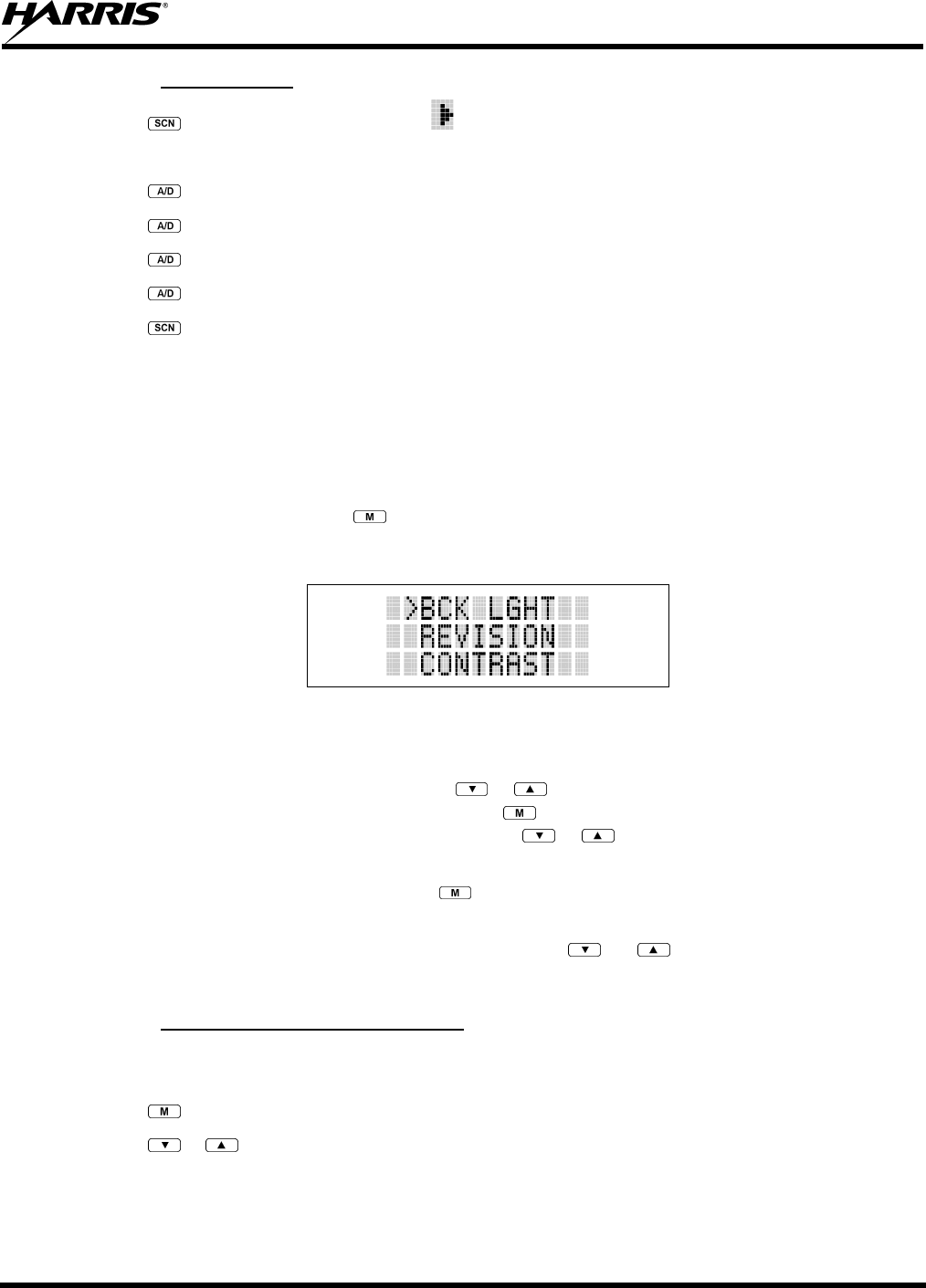
MM-013994-001, Rev. Ap1
123
11.9.2 P7350 Model
1. Press to toggle scan OFF and verify is not displayed.
2. Select group or channel.
3. Press once to remove group from the list.
4. Press once to add as a normal group.
5. Press twice to add as a Priority 2 group.
6. Press three times to add as a Priority 1 group.
7. Press to re-start scanning.
11.10 MENU
The Menu function accesses features that are not available directly from the keypad. The order and actual
menu items available is configurable through programming. Upon radio power up, the menu item that is
at the top of the menu list will always be displayed first. Subsequent access to the menu function will
return the last menu item that was shown in the display and cursor position.
1. To enter the menu mode, press .
2. Upon entering the menu selection mode, Menu options will appear in the display (see Figure 11-8).
Figure 11-8: Menu Display
3. The radio will continue to receive and transmit normally while in the menu function.
4. To scroll through the menu options use the or keys. When the required menu item has been
found align the cursor with the option then press to select it. The menu item's parameter setting
shown in the display can now be changed by using or to scroll through the list of parameter
values.
5. Once the desired setting is reached press to store the value and return the menu option selection
level.
For menu items that display radio information, pressing or will scroll through a list of
informational displays. Possible menu items are listed in Table 11-5.
11.10.1 Menu Item Selection Process
An example of the backlight menu item selection process and menu item parameter change is shown in
Figure 11-9.
1. Press . The menu mode is entered.
2. Press or until the display shows:
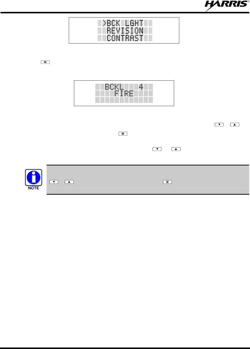
MM-013994-001, Rev. Ap1
124
Figure 11-9: Backlight Menu Item Selection Parameter
3. Press . The backlight menu item is activated. Line one shows the active menu item and its
current parameter setting. Line two shows the currently selected system or group name (see Figure
11-10).
Figure 11-10: Backlight Menu Display
4. The menu item's parameter setting shown in the display can now be changed by using or .
5. Once the desired setting is reached press to store the value and return the menu option selection
level.
For menu items that display radio information pressing or will scroll through a list of
informational displays. An example of information displays is shown in Table 11-6.
The TX POWER menu item, when selected, toggles LOW/HIGH power. It does not use
or to scroll nor is an additional press of the button required.

MM-013994-001, Rev. Ap1
125
Table 11-5: Menu Item Information
FEATURE DISPLAY PARAMETER
SETTING COMMENT
Keypad Lock Menu Item:
KEY LOCK
Once Selected:
LOCKED
Locked
Unlocked
Locks the keypad. To unlock; press and release then within 1
second press the option button NOTE: This sequence is also a short
cut to locking the keypad.
Backlight Adjust Menu Item:
BCK LIGHT
Once Selected:
BCKL=
OFF, 1 thru 6 Selects the light level for backlighting.
Contrast Adjust Menu Item:
CONTRAST
Once Selected:
CNTRST=
1, 2, 3, 4 Selects the display contrast level.
Transmit Power Select Menu Item:
TX POWER
Once Selected:
POWER=
HIGH or LOW Selects radio output power mode.
Radio Revision Information Menu Item:
REVISION
N/A Selects the information display to view. Informational display only. No
user selectable settings.
Toggle Scan On/Off SCAN ON/OFF Toggles Scan operation ON/OFF.
Toggle Private Mode PRIVATE ON/OFF Toggles Private Mode ON/OFF.
Display Current Encryption
Key
DISP KEY N/A Displays current encryption key. Informational display only. No
selectable settings.
Display Current Home
Group/Channel
HOME N/A Selects Home Group/Channel
Select Desired System SYS SEL N/A Selects a new system.
Add Group/Channel to
Scan List
SCAN ADD N/A Adds to Scan List.
Delete Group/Channel SCAN DEL N/A Deletes Group or Channel from Scan List.
Add/Delete Scan List SCAN A/D N/A Add or Delete from Scan List.
Select Telephone
Numbers From Phone List
PHN CALL N/A Trunked Only.
Data Operation NO DATA ON/OFF Trunked Only. Toggles Data Operation ON/OFF.
Select Individual Call from
IC List
IND CALL N/A Trunked Only.
Select Group GRP SEL N/A Trunked Only.
Feature Encryption Display Menu Item:
FEATURES
N/A Indicates current features programmed into the radio as well as certain
information required to add features to the radio. Informational display
only. No user selectable settings.
System Scan Enable Menu Item:
SYS SCAN
Once Selected:
SYSC ON or SYSC
OFF
ON/OFF Toggles System Scan feature ON/OFF.
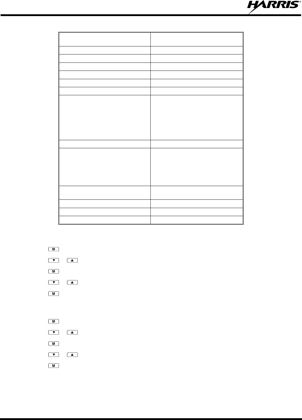
MM-013994-001, Rev. Ap1
126
Table 11-6: Information Display
RADIO ID
XXXXXXXX
LID in EDACS/EA In CONV it has no
meaning.
RAM SIZ RAM Size
FLSH SIZ Flash Size
RF BAND Frequency Band
PERS VER Software Version
DSP DATE Date DSP code was built.
DSP TIME Time DSP code was built.
DSP FEAT The DSP Features supported by the
DSP code, in Hexadecimal.
Bit mapped (see IPC spec for details):
• 0x0001 – Conventional
• 0x0002 – EDACS
• 0x0010 – AMPF
• 0x0020 – undefined
DSP VER DSP Software Version
FLSH VER FLASH Software
ex: P73U0102
P=portable, 54=5400 radio,
U=unencrypted, 01=major revision (>50
means unreleased code), 02=minor
revision
HARRIS
(C) 2009
Copyright
PERSNLTY Personality Name
BLD DATE Date host (ARM) code was built.
BLD TIME Time host (ARM) code was built.
11.11 BACKLIGHT ADJUST
1. Press to access the menu.
2. Press or to scroll through menu until “BCKLGHT” appears.
3. Press to select Backlight menu.
4. Press or to scroll through available settings OFF, 1 through 6.
5. Press to select new backlight setting.
11.12 CONTRAST ADJUST
1. Press to access the menu.
2. Press or to scroll through menu until “CONTRAST” appears.
3. Press to select Contrast menu.
4. Press or to adjust contrast setting from 1 - 4.
5. Press to select new contrast setting.
11.13 DECLARING AN EMERGENCY
1. Press and hold the red Emergency/Home button (the length of time is programmable; check with the
system administrator).
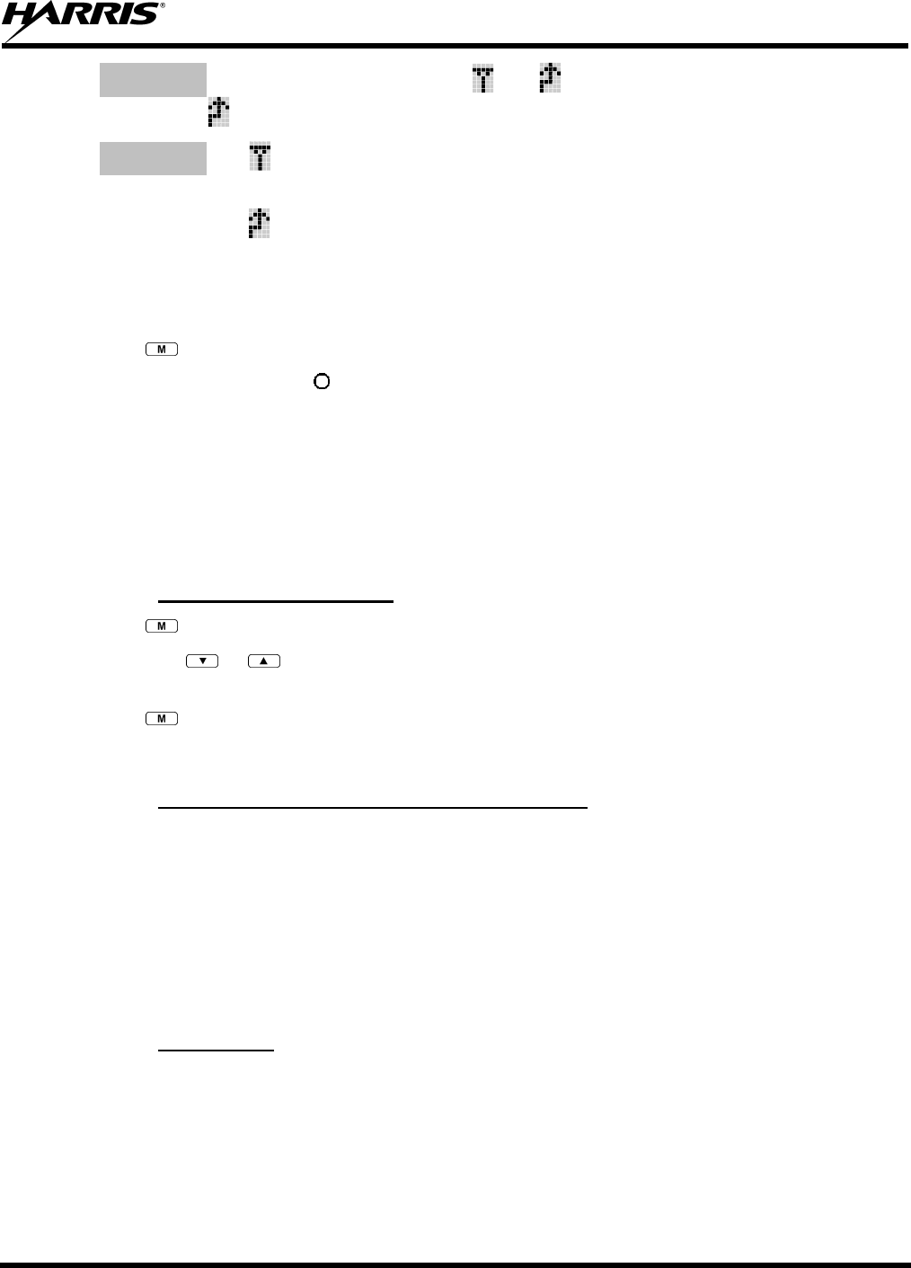
MM-013994-001, Rev. Ap1
127
2. *TXEMER* will flash in the display, plus and will be displayed. After 2-3 seconds the
transmit icon will turn off.
3. *TXEMER* and will remain until the emergency is cleared. Refer to Section 11.19 for more
detail regarding emergency operation.
4. Press the PTT and will reappear.
5. Release PTT when the transmission is complete.
11.14 LOCKING/UNLOCKING KEYPAD
1. Press button.
2. Within 1 second, press the button on the side of the radio.
11.15 HIGH/LOW POWER ADJUSTMENT
Transmit power adjustment is possible if enabled through programming. Within conventional systems,
transmit power is adjustable on a per channel basis. Within EDACS trunking systems, transmit power is
adjustable on a per system basis.
There are two ways to toggle between high and low power, described in Sections 11.15.1 and 11.15.2.
11.15.1 Using the Menu Button
1. Press .
2. Using the or keys, scroll until the cursor (>) appears to the left of “TX POWER” in the
display.
3. Press again to toggle between High and Low power.
4. “POWER = HIGH” or “POWER = LOW” will appear momentarily on the top line of the display.
11.15.2 Using the Pre-Programmed Option Button
Press the Option button. “POWER = HIGH” or “POWER = LOW” will appear momentarily on the top
line of the display.
11.16 DIGITAL VOICE OPERATION
Digital voice programmed systems have three (3) different voice modes: clear (analog), digital, and
private (encrypted). The voice modes are programmed on a per-group basis within each trunked system
and on a per-channel basis within each conventional system.
11.16.1 Clear Mode
The Clear Mode is a voice mode in which the radio transmits and receives only clear (analog) voice
signals. These analog signals are non-digitized and non-encrypted. Clear mode transmissions can be
monitored easily by unauthorized persons.

MM-013994-001, Rev. Ap1
128
Groups or channels programmed for clear operation cannot transmit or receive digital or
private messages.
11.16.2 Digital Mode
The Digital Mode allows the radio to transmit and receive digitized voice signals. Digital signals provide
improved weak signal performance and cannot be easily monitored with a standard receiver. Groups
programmed for digital operation transmit only digital signals. Message trunked group calls and
individual phone calls (I-Calls) are answered back in the mode in which they were received assuming the
call or hang time is still active. Individual phone, all call, and emergency calls are transmitted clear if the
digital mode is disabled or inoperative.
1. If receiving an analog message trunked call, the radio responds in the analog mode during the hang
time on the working channel.
2. If receiving an analog I-Call, the radio responds in the analog mode during the hang time.
3. When using the *WHC* feature to respond to an I-Call (after the hang time has expired), the call is
transmitted in the mode defined by the system mode as programmed for the current system if the ID
being called is not in the I-Call list. If the ID is in the I-Call list, then the call is transmitted as defined
by the I-Call mode programmed in the list for that ID.
The overdial DTMF tones are not available while in the Digital Mode.
11.16.3 Private Mode
The Private Mode allows the radio to transmit encrypted messages and receive clear or private
transmissions. The radio transmits private if the group is programmed for private operation and forced
operation is pre-programmed. If auto-select operation is pre-programmed and the radio is in the Private
Mode, the radio transmits in the mode of the received call if the hang time is active. If no hang time is
active, the radio transmits private.
Cryptographic keys are transferred to the radio using a cryptographic Keyloader. Up to seven (7)
different cryptographic keys, numbered 1-7, can be transferred from a Keyloader and stored in the radio.
An individual key is automatically selected on a per-group basis according to the radio programming.
Groups and channels within the digital system can be programmed for keys 1-7 (private). Up to 8 banks
of 7 keys can be stored for private systems. The bank is specified per system.
When operating on a group programmed for Private Mode, all transmissions are private transmissions and
the radio receives clear and private signals. The status icon is displayed when the Private Mode is
enabled. If the selected group is programmed for auto-select capability, the mode may be toggled
between private and clear with the key, then following the selection mode rules. Radios programmed
for forced private operation do not allow a change of the transmit mode.
11.16.3.1 Displaying the Currently Used Cryptographic Key Number
To display the currently used Cryptographic Key Number for either the system encryption key (for
special call such as individual, phone, all, agency or fleet) or the group key (for group calls), perform the
following procedure:
1. Press the button.
2. Use the or button to select "DISP KEY."
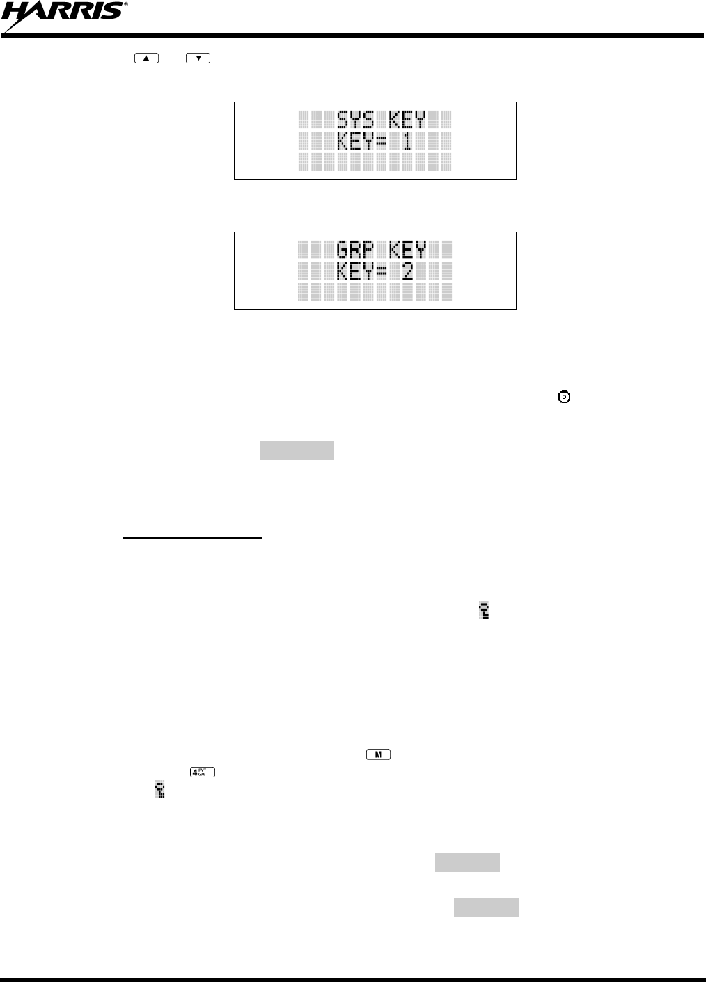
MM-013994-001, Rev. Ap1
129
3. Use the or button to toggle between displaying the system key (Figure 11-11) or the
group/channel key (Figure 11-12).
Figure 11-11: System Encryption Key Display
Figure 11-12: Group/Channel Encryption Key Display
11.16.3.2 Key Zero
All cryptographic keys can be zeroed (erased from radio memory) by pressing the button and while still
pressing this button, press and hold the OPTION button. Press both buttons for 2 seconds. A series of
beeps will begin at the start of the 2 second period and then switch to a solid tone after the keys have been
zeroed. The display will indicate KEY ZERO.
If the cryptographic key(s) are zeroed, one or more keys must be transferred from the Keyloader into the
radio before private communications may continue.
11.16.4 Private Operation
11.16.4.1 Receiving an Encrypted Call
When receiving, the radio automatically switches between clear or private operation. If the transmission
being received is an encrypted transmission, it will be decrypted, the icon is displayed, the receiver will
unsquelch and the message will be heard in the speaker. For this to occur, the selected group or channel
must be programmed for private operation and the correct cryptographic key must be loaded into the
radio.
11.16.4.2 Transmitting an Encrypted Call
1. Select the desired group or channel.
2. Place the radio in Private Mode by pressing key; then follow the selection mode rules. On a
System radio, the key can be used to toggle the Private Mode ON/OFF. When Private Mode is
enabled, the icon is displayed.
3. If the last state of the radio was Private Mode, the Private Mode will be enabled on power up. Also,
the Private Mode will be enabled if forced operation has been programmed in the radio.
If a group is not programmed for Private Mode operation, PVT DIS will be displayed if an attempt is
made to enable private transmit mode. It is not possible to operate on this group in Private Mode.
If the radio does not have the correct encryption key loaded, NO KEY# will be displayed and the call
will not be transmitted.
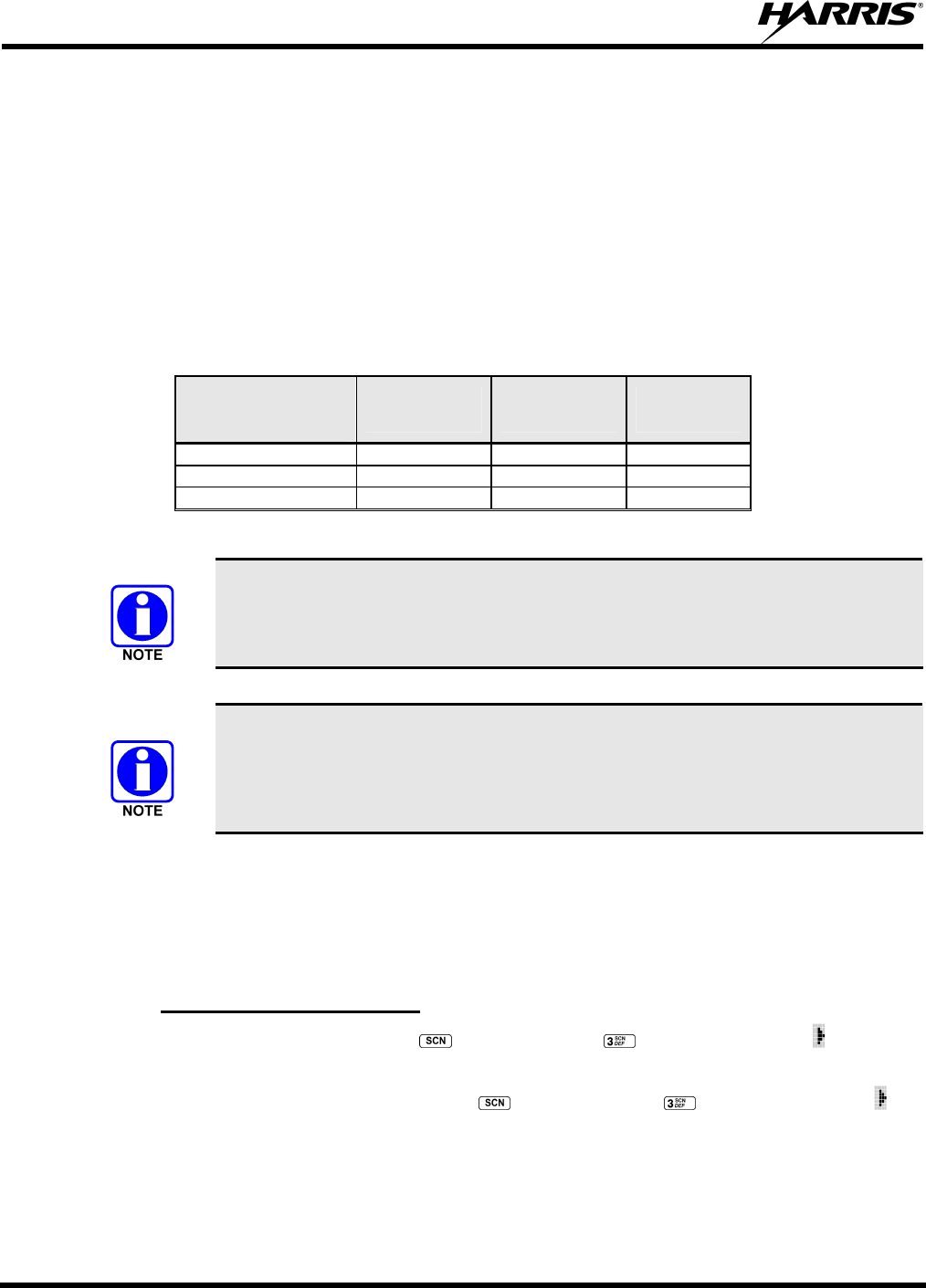
MM-013994-001, Rev. Ap1
130
4. Continue with standard transmission procedures. A Private Mode access tone will be heard when the
PTT button is pressed.
11.16.4.3 Scanned Group Calls
Receiving a Scanned Group Call is the same as receiving a selected group call. During the scan hang
time, if the radio was programmed for auto-select, it will transmit back in the same mode it received the
call. For example, if a clear group is entered in the scan list, it will only receive clear calls. If the same
group was available in private and entered in the scan list, it can receive clear and private calls, provided
auto-select was programmed in the radio. The user can select transmitting on the scanned or selected
group. If a group is entered in the scan list more than once, and in different modes (clear, digital, or
private), only the first occurrence of the group will be used.
Table 11-7: Transmit/Receive Mode Compatibility for Digital Voice Operation
GROUP
PROGRAMMING
(TRANSMIT)
CLEAR
RECEIVE DIGITAL
RECEIVE PRIVATE
RECEIVE
CLEAR Yes No No
DIGITAL Yes Yes No
PRIVATE Yes No Yes*
*assumes the proper cryptographic key is loaded
Conventional digital or encrypted channels require Channel Guard on the channel to
operate correctly.
The voice coding technology embodied in this product is protected by intellectual
property rights including patent rights, copyrights, and trade secrets of Digital Voice
Systems, Inc. The user of this technology is explicitly prohibited from attempting to
de-compile, reverse engineer, or to disassemble the Object Code, or in any other way
convert the Object Code into a human-readable form.
11.17 SCANNING TRUNKED GROUPS
Groups that have been previously added to the scan list on a per system basis may be scanned. Each
system's group scan list is retained in memory when the radio is powered OFF or when the battery pack is
removed.
11.17.1 Turning Scan On and Off
1. Toggle Scan operation ON by pressing (P7350 model) or (P7370 model). The icon rotates
clockwise to indicate radio is scanning.
2. Toggle Scan operation OFF by again pressing (P7350 model) or (P7370 model). The will
disappear.
• If the radio scans to a group other than the selected group then receives a call on the selected
group, the radio will switch to the selected group. However, if the “scanned-to” group is
programmed at a higher priority the radio will remain on the “scanned-to” group.
MM-013994-001, Rev. Ap1
131
• The radio will continue scanning if a new group is selected when scan is ON.
3. Pressing the PTT button when scan is ON will cause the radio to transmit on the displayed group or to
the currently selected group (depending on programming).
11.17.2 Adding Groups to a Scan List
P7350 Model Radio
1. Scan must be OFF to add/delete groups to/from the scan list. If the Scan icon is ON, press the
key to turn Scan OFF.
2. Select the desired group using the System/Group/Channel control knob and/or the or keys.
If the selected group is currently on the list, pressing will display on line three.
3. If the scan list status icon is blank ( ), the group can be added to the scan list by pressing the key.
will be displayed on line three.
4. Press the key a second time to set the group to Priority 2. A is displayed on line three.
5. Press a third time to set the group to Priority 1. A is displayed on line three. The priority level
section sequence only advances the group to the next high priority level and stops at priority level 1.
To select a lower priority level, the group must be deleted from the scan list and then added back to
the scan list. Each new group added to the scan list starts at the lowest priority. If the Priority 1 and
Priority 2 groups are already set and a new group is assigned as Priority 1 or Priority 2, the previously
assigned group will change to non-priority scanning. One of the following messages may be
momentarily displayed.
SCAN DIS The radio is not programmed to scan.
FIXED P1 A Priority 1 group has been pre-programmed into the radio. A new Priority 1 group
cannot be selected.
FIXD LST A fixed scan list has been pre-programmed into the radio. It is not possible to change
the list without reprogramming the radio.
To quickly view multiple group scan status, press then slowly but consistently rotate
the group knob. Each group status will appear on the display.
P7370 Model Radio
1. With scan operation turned OFF, select the desired group to add to the selected trunked system group
scan list.
2. Press . The current priority status of the group will be displayed in column 10 of line three for a
time-out period. If the group is not part of the scan list the status will be blank.
3. While the status is displayed, press to add the group to the scan list. is displayed on line three.
4. Press a second time to set the group to Priority 2. A is displayed on line three.
5. Press a third time to set the group to Priority 1. A is displayed on line three. The priority level
selection sequence only advances the group to next higher priority level and stops at priority level 1.
MM-013994-001, Rev. Ap1
132
To select a lower priority level, the group must be deleted from the scan list and then added back to
the scan list. Each new group added to the scan list starts at the lowest priority. If the Priority 1 and
Priority 2 groups are already set and a new group is assigned as Priority 1 or Priority 2, the previously
assigned group will change to non-priority scanning. One of the following messages may be
momentarily displayed.
SCAN DIS The radio is not programmed to scan.
FIXED P1 A Priority 1 group has been pre-programmed into the radio. A new Priority 1 group
cannot be selected.
FIXD LST A fixed scan list has been pre-programmed into the radio. It is not possible to change
the list without reprogramming the radio.
To quickly view multiple group scan status, press either or the key. Then
slowly but consistently rotate the group knob. Each group status will appear on the
display.
11.17.3 Deleting Groups from a Scan List
P7350 Model Radio
1. With scan operation turned OFF, select the desired group to delete from the selected trunked system
group scan list.
2. Press . The current status of the group is displayed for a time-out period.
3. While the current status is displayed, press until the group from the scan list is "blank." The
sequence is "blank," , , , "blank." Any group that is not in a trunked system group scan list will
show a "blank" for the time-out period when it is the selected channel.
P7370 Model Radio
1. With scan operation turned OFF, select the desired group to delete from the selected trunked system's
group scan list.
2. Press . The current status of the group is displayed for a time-out period.
3. While the status is displayed, press to delete the group from the scan list. , , or turns OFF.
Any group that is not in a trunked system group scan list will show a "blank" for the time out period
when it is the selected channel.
11.17.4 Nuisance Delete
A group can also be deleted from the scan list, if it is not the currently selected group, by pressing the
key (P7350 model) or the key (P7370 model) during scan operation while the radio is displaying the
unwanted group. The group will be deleted from the system's group scan list in the same manner as if
done using the steps above. Deletions done in this manner will not remain deleted if the radio is powered
OFF and then powered ON.
11.18 SCANNING TRUNKED SYSTEMS
The radio can be programmed with the following System Scan features. These features are automatically
enabled when the radio is powered ON. A key or menu option is also defined to allow the System Scan

MM-013994-001, Rev. Ap1
133
features to be toggled during radio operation. The System Scan state will be maintained through system
changes but will default to ON when the radio is powered ON.
Enable/Disable via Menu Selection
Press and then use the or buttons to scroll through the selections until SYS SCAN is
displayed. Then press to toggle the System Scan state. The SYSC ON or SYSC OFF display
message is displayed for two seconds to show the new state.
Enable/Disable via Pre-Programmed Keypad Key
Press the key pre-programmed to toggle System Scan and the SYSC ON or SYSC OFF display message
is displayed for two seconds to show the new state.
11.18.1 Wide Area System Scanning
The P7300 series radio can be programmed for Wide Area System Scan operation for roaming across
mobile systems. Upon the loss of the currently selected system's control channel, radios can be
programmed to automatically scan the control channels of other systems. If a new control channel is
found, the radio will switch to the new system and sound an alert tone.
11.18.2 Priority System Scan
The radio can also be programmed for Priority System Scan. The priority system is the desired or
preferred system. While receiving the control channel of the selected system, the radio will periodically
leave the selected system and search for the control channel of the priority system. This is done at a
programmable rate defined by the value in the Priority Scan Time control (unless the ProScan™ algorithm
is enabled, as explained in the following sections). This priority scan timer is reset each time the PTT
button is pressed or when the call is received. If the priority system control channel is found, (or meets the
predefined criteria <ProScan>), the radio will automatically switch to the priority system.
11.18.2.1 Enabling the Wide Area System Scan Function
If the radio cannot find the control channel of the selected system and begins to wide area system scan,
the radio will only scan for the priority system control channel if the priority system is in the wide area
scan list.
11.18.2.2 When ProScan is Enabled
The radio monitors the priority system and will switch to the priority system if the criteria defined by the
controls in the ProScan Options dialog box are met. If ProScan is enabled, the rate at which the radio will
scan for the priority system is defined by the System Sample Time control, located in the ProScan
Options dialog box. See Section 8.20.3 for more information on ProScan.
11.18.3 ProScan
The radio may be programmed for ProScan system scan operation for multi-site applications depending
on the version of radio flash code. ProScan is an improved multi-site system scanning algorithm designed
to replace ProSound™ scanning. ProScan provides the radio with the ability to select a new system for the
radio to communicate on, when the selected system drops below a predefined level. This is accomplished
by enabling each radio to analyze the signal quality of its current control channel and compares it with the
signal quality of the control channel for each site in its adjacent scan list. (The signal quality metric used
for the ProScan algorithm is based on a combination of both Received Signal Strength Indicator (RSSI)
and Control Channel Verification (CCV) measurements.) When the selected system degrades to a pre-
programmed level, the radio will begin to look for a better control channel. Once a control channel that
MM-013994-001, Rev. Ap1
134
exceeds the pre-programmed parameters is found, the radio will change to the new system and emit a tone
(if enabled through programming). If the control channel is completely lost, the radio will enter Wide
Area System scanning and search the programmed adjacent systems until a suitable control channel is
found.
11.19 EMERGENCY OPERATION
The radio's ability to declare an emergency, clear an emergency, remain locked on an emergency system
and group, and the emergency audio and display freeze can each be enabled or disabled through
programming. When an emergency is declared scanning will stop and restarts only after the emergency
has been cleared.
11.19.1 Receiving an Emergency Call
When receiving an Emergency Call on the selected group and system, an alert beep is heard and is
displayed. The message *RXEMER* flashes in the display on line two until the emergency condition is
cleared.
11.19.2 Declaring an Emergency Call
Perform the following steps to send an emergency call to a selected system and group (or on an optionally
pre-programmed group).
1. Press and hold the red EMERGENCY button that is on top of the radio in front of the antenna for
approximately one second (this time is programmable and therefore could be longer or shorter; check
with the system administrator). The radio will transmit an emergency call request with the radio ID
until an emergency channel assignment is received.
2. When the working channel assignment is received, the radio sounds a single beep indicating the radio
has auto keyed (see Table 8-4) and is ready for voice transmission. *TXEMER* flashes on line two in
the display until the emergency is cleared.
3. Press PTT and speak into the microphone in a normal voice. and momentarily turn ON.
4. Release PTT when the transmission is complete.
To clear the emergency first press and hold the button. While continuing to hold the button, press the
EMERGENCY button. (This will work if the radio is programmed to clear emergencies.)
11.20 INDIVIDUAL CALLS
11.20.1 Receiving and Responding to an Individual Call
When the radio receives an individual call (a call directed only to the user's radio), it un-mutes on the
assigned working channel and displays . The first line on the display shows the logical ID number of the
unit sending the message, or the associated name if the ID number is found in the individual call list. The
radio can be programmed to ring when an individual call is received. If enabled, the ring begins five
seconds after the caller un-keys and will continue until the PTT button, the button or the individual call
mode is entered.
The volume of the ring is adjustable through the volume control levels.
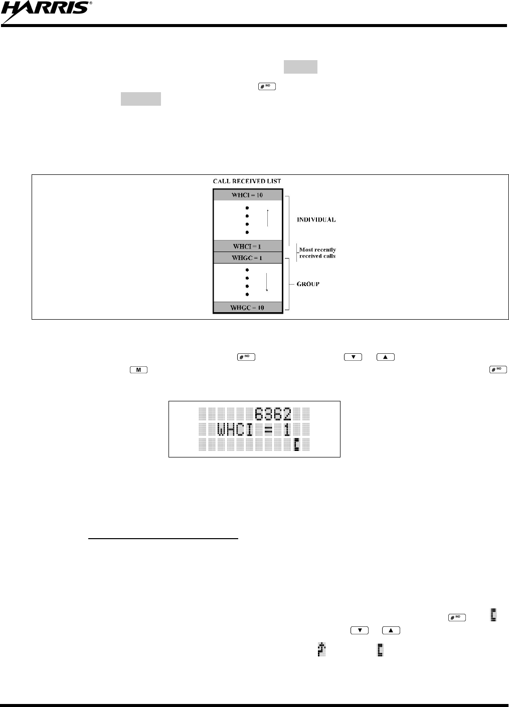
MM-013994-001, Rev. Ap1
135
If a response is made by pressing the PTT to the call prior to the programmed call-back time-out, the call
will automatically be directed to the originating unit. If a response is not made before the call-back time-
out, the radio will return to normal receive display, and *WHC* will appear on the first line of the LCD.
To respond after the call-back time-out, press the key. The radio's display will show the callers ID on
the first line and WHCI=1 on the second line. Pressing the PTT button at this point will initiate an
individual call back to the original caller.
The radio stores the IDs of the last 10 callers in the Calls Received List as shown. Individual calls are
stored in the top half of the list (1-10) and Group calls are stored in the bottom half of the list (1-10). The
most recent call is stored in position 1, the second most recent call is stored in position 2, etc.
Figure 11-13: Calls Received Lists
To access the Calls Received List, press the key twice. Use the or buttons to scroll through
the list. Pressing the key will display the time elapsed since the call was received. After pressing
the display will appear similar to Figure 11-14.
Figure 11-14: WHC Individual Call Display
Pressing the PTT will initiate an individual call to the displayed logical ID. Powering the radio OFF and
ON will clear this list.
11.20.2 Sending an Individual Call
11.20.2.1 Pre-Stored Individual Calls
The following procedures describe how to initiate and complete a Pre-Stored Individual Call.
P7370 Model Radio
1. To select a pre-stored individual phone number, enter the individual call mode using the key. is
displayed. Then scroll through the list of stored numbers using the or keys.
2. Press the PTT button; when the radio is clear to transmit, turns ON, turns OFF and the channel
access tone sounds. Line one shows the called individual's name if found in the list of stored
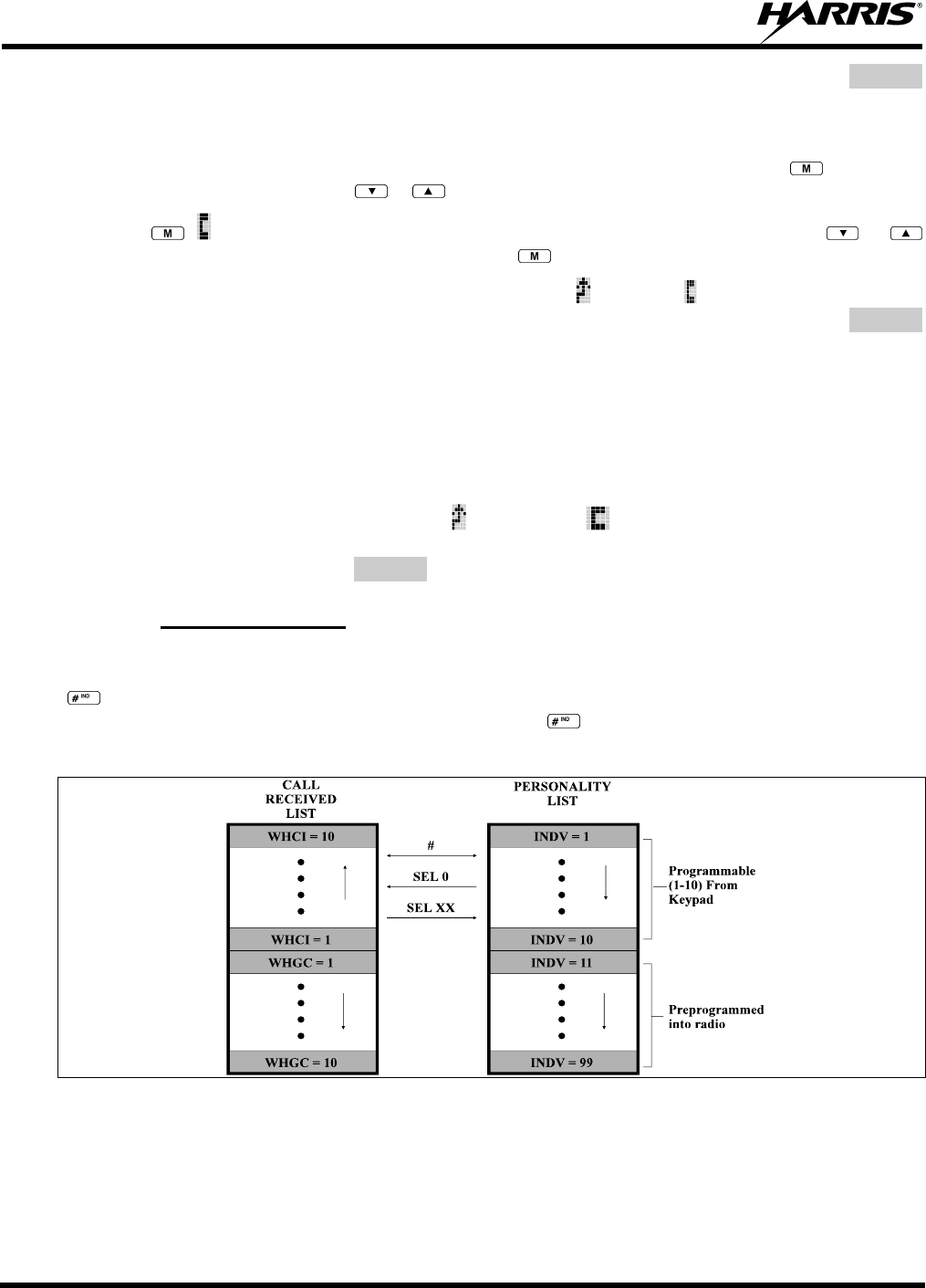
MM-013994-001, Rev. Ap1
136
individuals or LID followed by the logical ID number of the unit being called. The message *INDV*
displays on line two.
P7350 Model Radio
1. To select a pre-stored individual number, enter the menu mode by pressing the key. Scroll
through the mode list using the or buttons.
2. Press . is displayed. Scroll through the list of stored phone numbers using the or
buttons until the desired number is displayed. Press .
3. Press the PTT button; when the radio is clear to transmit turns ON, turns OFF and the channel
access tone sounds. Line one shows the called individual's name or LID. The message *INDV*
displays on line two.
11.20.2.2 Direct Dial Individual Calls (P7370 Model Only)
1. The following procedure describes how to initiate and complete a Direct Dial Individual Call.
2. The individual call ID is not stored in the pre-stored list of call IDs but the individual unit ID is
known, it can be entered directly from the keypad.
3. Press and hold the PTT button to transmit. will turn ON, will turn OFF, and the channel access
tone will sound. Line one shows the called individual's ID followed by the logical ID number of the
unit being called. The message *INDV* displays on line two. Proceed talking into the microphone.
11.20.3 Call Storage Lists
There are two lists available for call storage in the P7300 series radios, the calls received list (1 - 10) and
the personality list (1 - 99 as defined by the user). When the individual call mode is entered by pressing
, the calls received list is available. The user can toggle to the personality list by selecting any index
other than 0 or toggle between the two lists by pressing the key. If wrap is enabled, the calls received
list wraps on itself and not into the other list.
Figure 11-15: Calls Received and Personality Lists
The saved call list shows all ten storage locations. If no calls have been received, the saved call list will be
empty and the pre-stored list will be available upon entering the individual call mode.
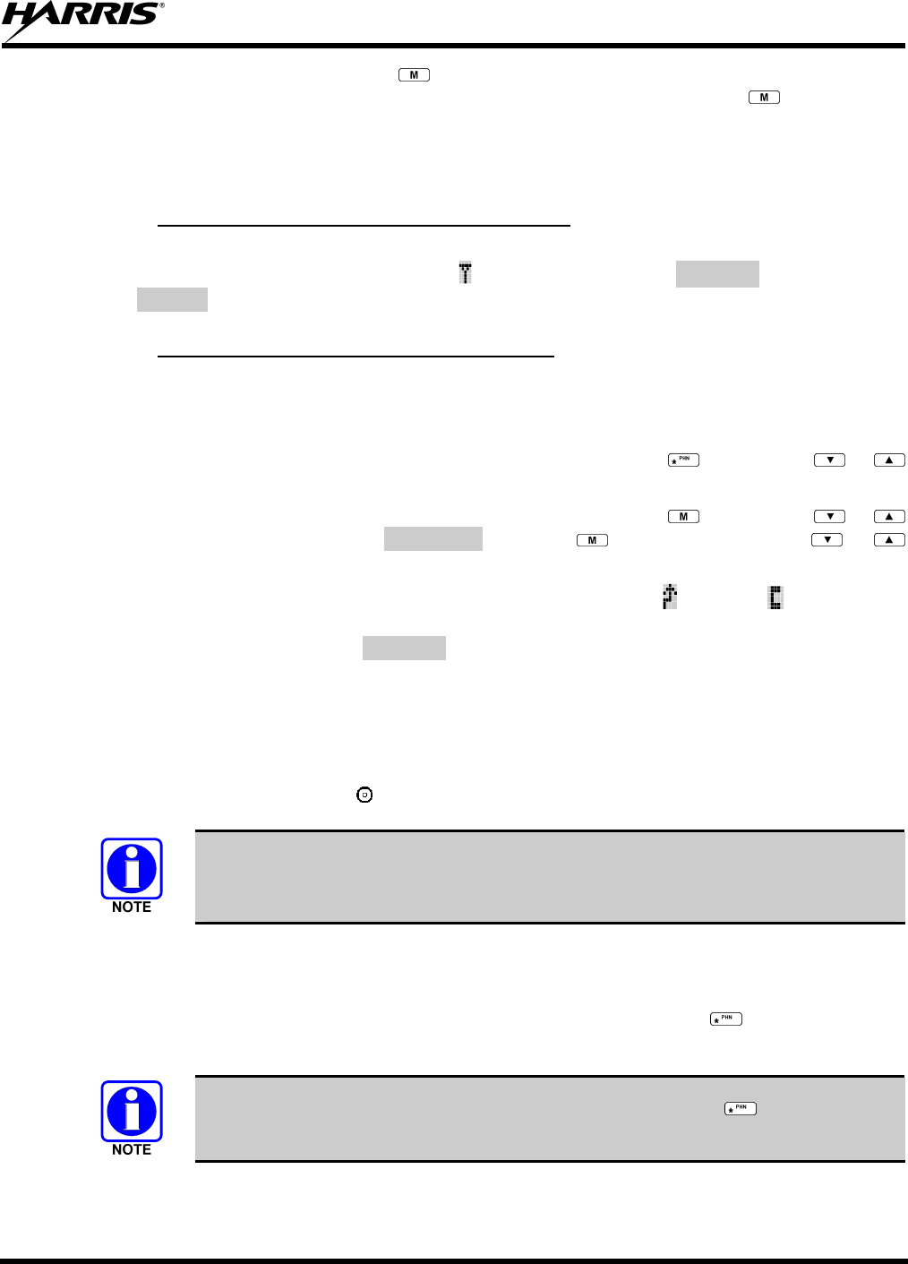
MM-013994-001, Rev. Ap1
137
When in the saved call list, pressing the key toggles the time stamp ON and OFF. The time stamp
indicates how long ago the call was received. When in the pre-stored list pressing the key toggles the
Logical IDentification (LID) ON and OFF.
11.21 TELEPHONE INTERCONNECT CALLS
11.21.1 Receiving a Telephone Interconnect Call
When the radio receives a telephone interconnect call (a call directed only to the user's radio), it un-mutes
on the assigned working channel and displays . The first line displays *PHONE*. The second line
displays *INDV*. Proceed with the call. Press the PTT to talk, release the PTT to listen.
11.21.2 Sending a Telephone Interconnect Call
11.21.2.1 Pre-Stored Number
Use the following procedures to initiate and complete a Telephone Interconnect call.
1. P7370 Model: To select a previously stored phone number, press the key. Use the or
buttons to scroll through the list of stored numbers.
P7350 Model: To select a previously stored phone number, press the key. Use the or
buttons to select the menu option PHN CALL. Press the key again then use the or
buttons to scroll through the list of pre-stored numbers.
2. Press and release the PTT button. When the radio is clear to transmit, turns ON, turns OFF and
the channel access tone sounds. Line one shows the accompanying name selected from the list of
stored numbers. The message *PHONE* appears on line two of the display. The radio then
automatically transmits the programmed number stored in the special call queue.
3. A telephone ring will be heard from the speaker. When someone answers the phone, press the PTT
button and speak into the microphone. Release the PTT button to listen to the callee. Unsuccessful
interconnect signaling returns the radio to the normal receive mode and the number remains displayed
until the special call is cleared or the time-out expires or another group or system is selected.
Terminate a call by pressing the button.
In half-duplex mode, only one person may talk at a time. The radio PTT button needs
to be pressed in order to communicate to the individual called and released for the
individual called to be heard.
11.21.2.2 Direct Dialing of Phone Calls (P7370 Model Only)
1. If the phone number is not stored in the pre-stored list of phone numbers, but the phone number is
known, it can be entered directly from the keypad. Start by pressing the key, then enter the
required number from the keypad. Press and release the PTT button.
The last number directly entered can be recalled by first pressing then pressing the
PTT button.
2. A telephone ring can be heard from the speaker. When someone answers the phone, press and hold
the PTT button and speak into the microphone. Release the PTT button to listen to the individual
MM-013994-001, Rev. Ap1
138
called. Unsuccessful interconnect signaling returns the radio to the normal receive mode and the
number remains displayed until the special call is cleared or the time-out expires or another group or
system is selected.
3. To terminate the call, momentarily press the button.
11.21.3 Dual-Tone Multi-Frequency: Overdial/Conventional Mode
Once the radio has established a connection to the public telephone system, it may be necessary to “over-
dial” more digits to access banking services, answering machines, credit card calls, or other types of
systems that require Dual-Tone Multi-Frequency (DTMF) access digits.
Overdial operation can also be used to initiate a telephone interconnect call via DTMF signaling if a dial
tone has already been accessed on the system. This method makes a telephone interconnect call while
operating in the conventional mode but will also function in trunked mode if a dial tone is directly
accessible.
Telephone numbers and other number sequences for overdialing can be stored in the phone list when
programming the radio. These numbers are accessed by pressing the key, then following the selection
mode rules. Perform the following procedures to access and dial these stored numbers.
P7350 Model Radio
1. Follow the procedure in Section 11.21.3 to establish a connection to the telephone system or consult
the system administrator for the procedure to access a dial tone on the trunked or conventional
system.
2. Enter selection mode first to enable entry of Overdial numbers by pressing the button.
3. Follow the selection mode rules to call up a stored number from the phone list: Use the or
buttons to scroll through the list of stored numbers. is displayed. Press the PTT to send the overdial
sequence once. If the number needs to be transmitted again it must be selected or entered again (this
prevents unwanted numbers from being sent the next time the PTT button is pressed during the call).
Overdial select/entry mode remains active until the call is dropped, cleared, or is pressed. The
overdial select/entry mode can be re-entered if the call is still active by pressing .
P7370 Model Radio
1. Follow the procedure in Section 8.23.2 to establish a connection to the telephone system or consult
the system administrator for the procedure to access a dial tone on the trunked or conventional
system.
2. Overdial numbers are transmitted using one of the following methods:
METHOD 1: 1. Enter the overdial selection mode by pressing the button.
2. Use the or buttons to scroll through the list of stored numbers. is
displayed. Press the PTT to send the overdial sequence once. If the number needs
to be transmitted again it must be selected or entered again (this prevents unwanted
numbers from being sent the next time the PTT button is pressed during the call).
Overdial select/entry mode remains active until the call is dropped, cleared, or
is pressed. The overdial select/entry mode can be re-entered if the call is still active
by pressing .

MM-013994-001, Rev. Ap1
139
METHOD 2: (P7370 model radios only)
1. Enter the overdial selection mode by pressing the button.
2. Press and hold the PTT button while entering the overdial number sequence from
the keypad. This method sends DTMF tones during individual, telephone
interconnect, trunked group, or conventional channel calls. Press the PTT to send
the overdial sequence once. If the number needs to be transmitted again it must be
selected or entered again (this prevents unwanted numbers from being sent the nex
t
time the PTT button is pressed during the call). Note: Anytime the PTT button is
pressed and held, the keypad is enabled for DTMF entry.
Overdial select/entry mode remains active until the call is dropped, cleared, or
is pressed. The overdial select/entry mode can be re-entered if the call is still active
by pressing .
This overdial select/entry mode remains active until dropped, cleared, or is pressed. The overdial
select/entry mode can be re-entered if the call is still active by pressing the button.
11.22 PROGRAMMABLE ENTRIES
11.22.1 Pre-Storing Individual and Telephone Interconnect Calls from the
Keypad
Individual Call ID numbers, telephone numbers, and other number sequences for overdialing are stored in
the special calls lists when programming the radio. The first ten entry locations of these lists can be
changed by the radio operator. The keypad is used when adding, changing, and storing numbers in these
entry locations.
Use the following procedure to store a number in one of the first ten entries of a special call list:
1. Press the or button to enter the individual call list or the phone call list. is displayed.
2. Scroll through the list using the or keys until one of the first ten entries is reached. NO
ENTRY is displayed if the location is empty.
3. Enter the desired number. If necessary, a pause can be entered by pressing and holding 0-9, , or
until an underscore appears in the display (telephone interconnect only). The individual call list
entries will accept up to 5 digits. The phone call list entries accept a combination of up to 31 digits
and pauses.
4. Press and hold the key until the display changes indicating that the number has been stored.
Repeat steps 1-4 to store additional numbers, to change numbers already stored, or to change the storage
location of a number.
11.23 STATUS/MESSAGE OPERATION
The Status and Message operations allow for the transmission of a pre-programmed status or a pre-
programmed message to an EDACS site. Each Status and Message is assigned an ID then cross-
referenced with the representative status condition (“Off Duty,” for example) or a message (“Call home”).
In addition, Status conditions can also be associated with a programmable Menu entry (required for
second method of transmitting a Status condition (see Section 8.25.1).
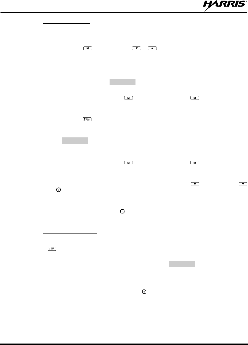
MM-013994-001, Rev. Ap1
140
11.23.1 Status Operation
P7370 Model Radio
One of two methods can be used to transmit a status condition.
METHOD 1: 1. Press the key, then use the or buttons to scroll to the pre-programmed
status condition. STATUS and 0 through 9 pre-programmed status selections are
available from the menu.
2. If STATUS is selected, you need to enter the number of the status condition you
intend to transmit. If no status has been programmed for the selected number key,
the radio will display NO ENTRY. A valid selection will display the status for a pre-
programmed time.
After the time-out expires or the key has been pressed (the key will override the
time-out period), the status is selected and will be transmitted to the site or stored in the
radio memory where it can be polled by the site at a future time.
METHOD 2: 1. Press the key.
2. Press the corresponding pre-programmed 0 through 9 status condition key. If no
status has been programmed for the selected number key, the radio will display
NO ENTRY. A valid selection will permit the status condition to appear in the top
line of the display and the status ID to appear in the second line of the display for a
pre-programmed time.
After the time-out expires or the key has been pressed (the key will override the
time-out period), the status is selected and will be transmitted to the site or stored in the
radio memory where it can be polled by the site at a future time.
View the currently selected status after it has been transmitted by pressing the key and then the
key and then the button prior to the time-out period. If the status was not sent successfully to the site,
the text associated with the status condition will flash in the display.
The status selection can be changed by pressing a different status key 0 through 9, or the status operation
can be cancelled by pressing Option Button 2 . Both operations must be carried out prior to the time-
out period.
11.23.2 Message Operation
The following method can be used to transmit a message using the Message Operation.
1. Press the key.
2. Press the corresponding 0 through 9 pre-programmed “message” key. If no message has been
programmed for the selected number key, the radio will display NO ENTRY. A valid selection will
permit the message to appear in the top line of the display and the message ID to appear in the second
line of the display for a pre-programmed time.
The message selection can be changed by pressing a different message key 0 through 9, or the message
operation can be cancelled by pressing Option Button 2 . Both operations must be carried out prior to
the pre-programmed time-out period.
11.24 MACRO KEY OPERATION
Macro key operation permits the user to accomplish a series of keystrokes with a single "macro"
keystroke. Each Macro Key is capable of executing up to twenty (20) keystrokes, to any push button input

MM-013994-001, Rev. Ap1
141
(i.e., keypad keys, OPTION buttons, etc.). Each macro key can be pre-programmed to activate when
pressed or when released.
A macro key may also be pre-programmed to change the key stroke sequence the next time the macro key
is activated.
For detailed operation and assignment of macro keys, contact your communications supervisor or
administrator.
11.25 PORTABLE DATA
The P7300 series portable radios, when operating in the EDACS Trunked configuration, permit both
voice and data calls to be transmitted and received. The radio can handle only one type of call at a time;
however, either data or voice is selected transparently by the operator through normal usage of the radio.
Data communications is not supported in conventional mode.
The radios can be connected to a Mobile Data Terminal (MDT) or to a host computer. Any RS-232
compatible device that supports the Radio Data Interface (RDI) protocol (Version 1.91 or greater) may be
connected to the radio. Support for MDTs or host computers is a programmable option per radio.
Additionally, radios may also be programmed for data only operation (no voice calls transmitted or
received).
11.25.1 Displays
The following will be displayed during the various states of data mode of operation:
TX DATA Appears on top line of display when the radio is transmitting a data call.
RX DATA Appears on top line of display when the radio is receiving a data call.
DATA OFF Appears on top line of display when the radio is in the data disabled state.
DATA ON Appears for two seconds on top line of display when the radio is toggled to the data
enabled state.
11.25.2 DATA OFF Operation
The radio can be placed in the data disabled state by any of the following methods. When the data state is
disabled, DATA OFF appears on the top line of the display.
• Declaring an emergency (not to be used unless an actual emergency condition exists). Alert tone will
sound.
• Pressing Option Button 1 (if pre-programmed as “no data” key). Alert tone will sound.
• Pressing the pre-programmed “no data” (ND) key. Refer to previous bullet.
11.25.3 DATA ON Operation
The data state is enabled by one of the following (depending on how it was disabled). DATA ON will
appear on the top line in the display for two seconds then the display will return to normal.
• Pressing the pre-programmed “no data” (ND) key toggles data state ON or OFF.
• Clearing an emergency. This is valid only if the emergency caused “DATA OFF” operation.

MM-013994-001, Rev. Ap1
142
11.25.4 Exiting Data Calls
Under normal conditions, the radio enters the scan lockout mode and returns to the control channel after
completion of a data call (transmit or receive). If, during a data call, one of the following operations
occurs, the data call is immediately terminated and the radio performs the desired function:
• If the PTT is activated.
• If an Emergency is declared by pressing the pre-programmed emergency button.
• If a group or system is changed.
11.25.5 Scan Lockout Mode
Following the transmission or reception of a data call, if scan is enabled, scanning will stop temporarily.
There are two independent pre-programmed times associated with this mode; one after a received data
call and one after a transmitted data call. During this time the scan indicator will flash to indicate that scan
is enabled but temporarily suspended. This condition typically returns to normal scan operation when the
pre-programmed time expires; however, the following operations and conditions will terminate the scan
lockout mode before the timeout has expired.
• Press the button.
• Press the PTT.
• Change a group or system.
• Enter Telephone Interconnect mode.
• Enter Individual call mode.
• Receive a new emergency assignment.
• Declare or clear an emergency.
• Receive an individual or phone call.
• Receive an Agency, Fleet, or System All Call.
• Press (P7350 model) or (P7370 model) to toggle Scan ON or OFF.
11.25.6 Data Lockout Mode
During the voice call scan hang time (pre-programmed) the radio will not receive data calls.
11.26 GROUP CALLS IN P25 MODE
11.26.1 Transmitting a Group Call
1. Select the desired P25 system. (P25 icon will appear in display.)
2. Select the Talk Group/Conventional Channel. (Selected simultaneously using either the
System/Group/Channel control knob or the group key.)
3. Press and hold the PTT.
4. When a grant tone is received (if enabled through programming) speak into the microphone.
5. Release PTT and wait for response.

MM-013994-001, Rev. Ap1
143
11.26.2 Receiving a Group Call
1. The radio will unmute according to the squelch mode defined in the radio personality (monitor,
normal, selective).
2. Select the desired P25 system and Talk Group/Channel or turn scan on and make sure the desired
channel is in the scan list.
3. When the radio receives a P25 call, the radio will unmute and the channel name will appear in the
display.
4. Press the PTT button to respond.
11.27 INDIVIDUAL CALLS IN P25 MODE
11.27.1 Transmitting an Individual Call
1. Select the desired P25 system. (The P25 icon will appear in the display.)
2. Select the radio unit to call (callee source ID) from the pre-programmed individual call list or enter
the ID number on the radio keypad.
3. Press and hold the PTT.
4. When grant tone is received (if enabled through programming) speak into the microphone.
5. Release the PTT.
11.27.2 Receiving an Individual Call
1. The radio will unmute according to the squelch mode defined in the radio personality (monitor,
normal, selective).
2. Select the desired P25 system and Talk Group/Channel or turn scan on and make sure the desired
channel is in the scan list.
3. When the radio receives a P25 call, the radio will unmute and the ID of the transmitting radio will
appear in the display.
4. Press the PTT button to respond.
5. Unanswered calls will appear in the Who Has Called (WHC) list.
11.28 EMERGENCY GROUP CALLS IN P25 MODE
There is no method available for a system-wide Emergency clear. An emergency group call
must be cleared on each individual radio.
11.28.1 Declaring an Emergency Group Call
1. Select the desired P25 system and Talk Group/Channel.
2. Press the red emergency button on the top of the radio. The radio will broadcast a short emergency
transmission with the emergency bit set. “TXEMER” will appear in the display of the transmitting
radio.

MM-013994-001, Rev. Ap1
144
3. While the PTT is NOT pressed, the mic will be open and the radio will broadcast an approximately 2
second transmission (e.g., background noise) which will be repeated at 10-30 second intervals.
4. Press the PTT to stop the short transmissions.
5. To send a voice message, press the PTT and speak into the microphone.
6. To clear an emergency from the transmitting radio, perform one of the following steps:
• Change systems.
• Change channels (if not prohibited by programming).
• Cycle power by turning radio off and then back on.
• Press the Clear and Emergency buttons simultaneously, providing the Clear Emergency option is
enabled in the Supervisory Options in the personality.
11.28.2 Receiving an Emergency Group Call
1. Select the desired P25 System and Talk Group/Channel.
2. When the radio detects an incoming Emergency Group Call, the radio will sound an alert tone and
“RXEMER” will appear in the display.
3. Voice or emergency transmissions will be heard at the receiving radio.
4. To clear an emergency from the receiving radio, perform one of the following steps:
• Change systems.
• Change channels (if not prohibited by programming).
• Cycle power by turning radio off and then back on.
• Press the Clear and Emergency buttons simultaneously, providing the Clear Emergency option is
enabled in the Supervisory Options in the personality.

MM-013994-001, Rev. Ap1
145
This page intentionally left blank

MM-013994-001, Rev. Ap1
146
TECHNICAL ASSISTANCE
AND
WARRANTY INFORMATION
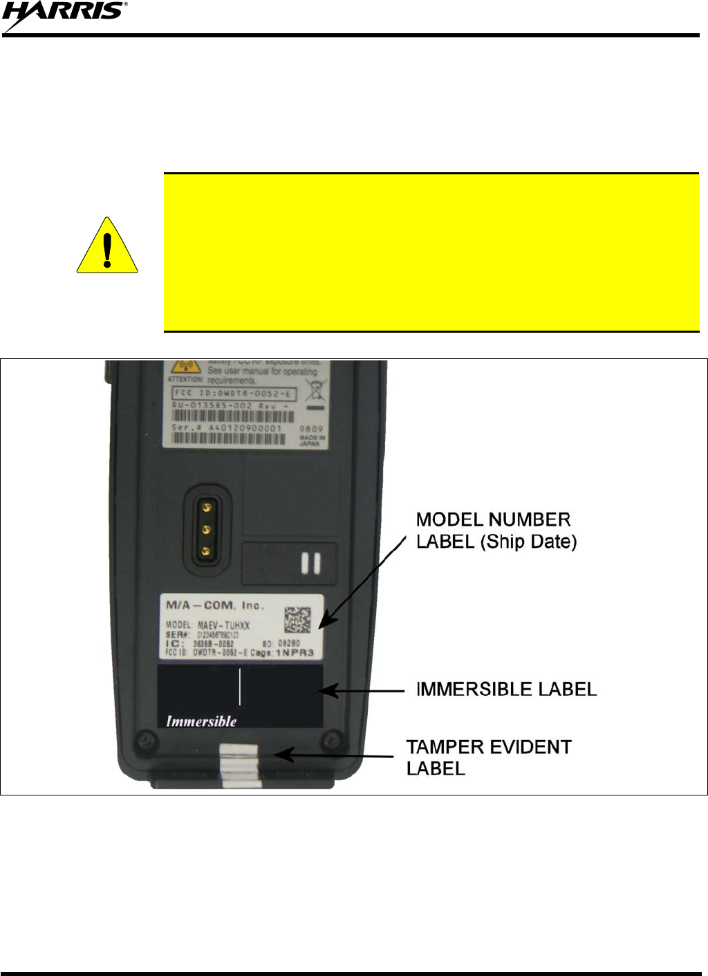
MM-013994-001, Rev. Ap1
147
12 IMMERSIBLE P7300 PREVENTIVE MAINTENANCE
Those P7300 radios labelled “immersible” (see Figure 12-1) require periodic testing using specialized
equipment to verify the radio’s watertight integrity.
Preventive Maintenance for Immersion-Rated Radios
CAUTION
P7300 multi-mode series portable radios with Immersion Option MAEV-MR must
be serviced by a service center authorized and certified by Harris to perform the
necessary tests to verify watertight integrity. As part of a thorough preventive
maintenance plan, Harris recommends Immersion-Rated P7300 multi-mode series
portable radios be, at a minimum, tested and re-certified on an annual basis. Harris
further recommends that the radios be tested on or close to the anniversary of the
ship date printed on the Model Number label on the back of the radio (see Figure
12-1).
Figure 12-1: Labels
12.1 TECHNICAL ASSISTANCE – IMMERSIBLE P7300
To preserve the watertight integrity of the P7300 portable radio, the radio must be serviced by a service
center authorized and certified by Harris to perform the necessary tests to verify the watertight integrity.

MM-013994-001, Rev. Ap1
148
Use one of the following methods to locate the nearest service center authorized to service the radios
warranted under Option MAEV-MR.
• Contact Harris Technical Assistance Center (TAC) at 1-800-528-7711 (in the U.S. and Canada)
or at 1-434-385-2400 (worldwide) for a listing of service centers authorized by Harris to service
P7300 radios with Option MAEV-MR.
or
• If a TECH-LINK subscriber, access Harris TECH-LINK web site for a list of Customer Service
Managers (CSM) or Regional Service Managers (RSM) that will provide a list of the nearest
service shops authorized by Harris to service P7300 radios with Option MAEV-MR.

MM-013994-001, Rev. Ap1
149
13 TECHNICAL ASSISTANCE
The Technical Assistance Center's (TAC) resources are available to help with overall system operation,
maintenance, upgrades and product support. TAC is the point of contact when answers are needed to
technical questions.
Product specialists, with detailed knowledge of product operation, maintenance and repair provide
technical support via a toll-free (in North America) telephone number. Support is also available through
mail, fax and e-mail.
For more information about technical assistance services, contact your sales representative, or call the
Technical Assistance Center at:
North America: 1-800-528-7711
International: 1-434-385-2400
Fax: 1-434-455-6712
E-mail: tac@tycoelectronics.com
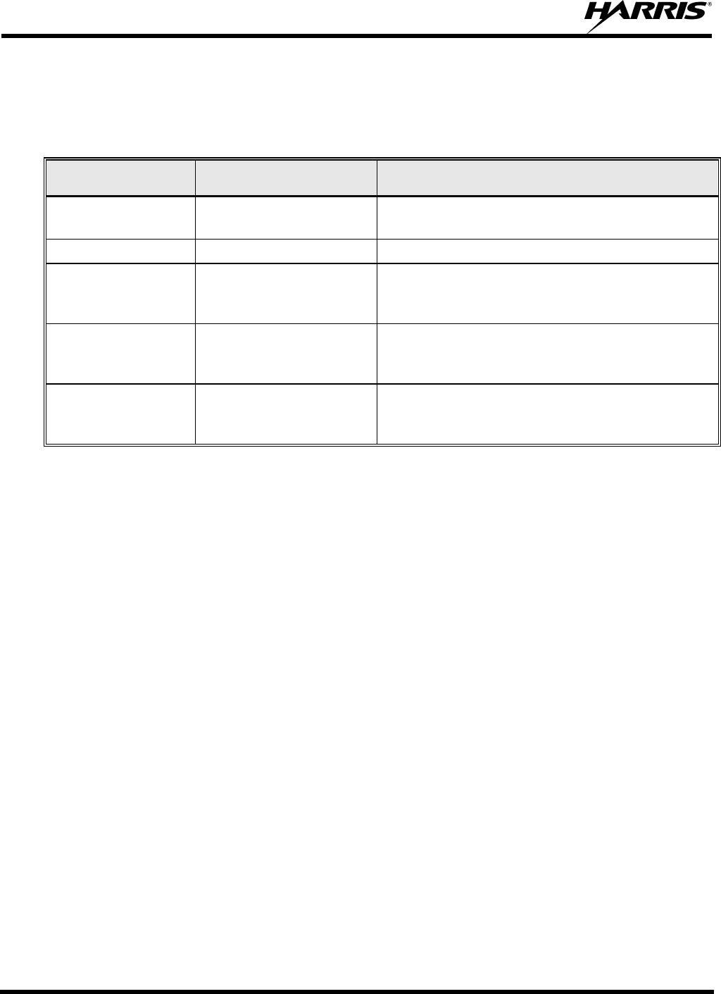
MM-013994-001, Rev. Ap1
150
14 BASIC TROUBLESHOOTING
Use Table 14-1 as a troubleshooting guide if the radio is not functioning properly. If additional assistance
is required, contact a qualified service technician or call Harris at 1-800-528-7711.
Table 14-1: Troubleshooting
SYMPTOM POSSIBLE CAUSE POSSIBLE SOLUTION
Radio will not turn
on. Low battery charge. Change the battery pack to a fully charged pack.
No Audio. Speaker volume is muted. Increase the volume level.
Poor Audio. User is in a poor coverage
area or not on the
network.
Move to a better coverage area.
Radio powers off for
no apparent reason. Radio may be
experiencing very low
voltage.
Have the battery checked by an authorized
technician.
Radio will not
transmit. Radio may be out of
coverage area or may be
overheated.
Return to coverage area if possible. If overheated,
let radio cool before retrying transmission. Report
this failure to an authorized technician.
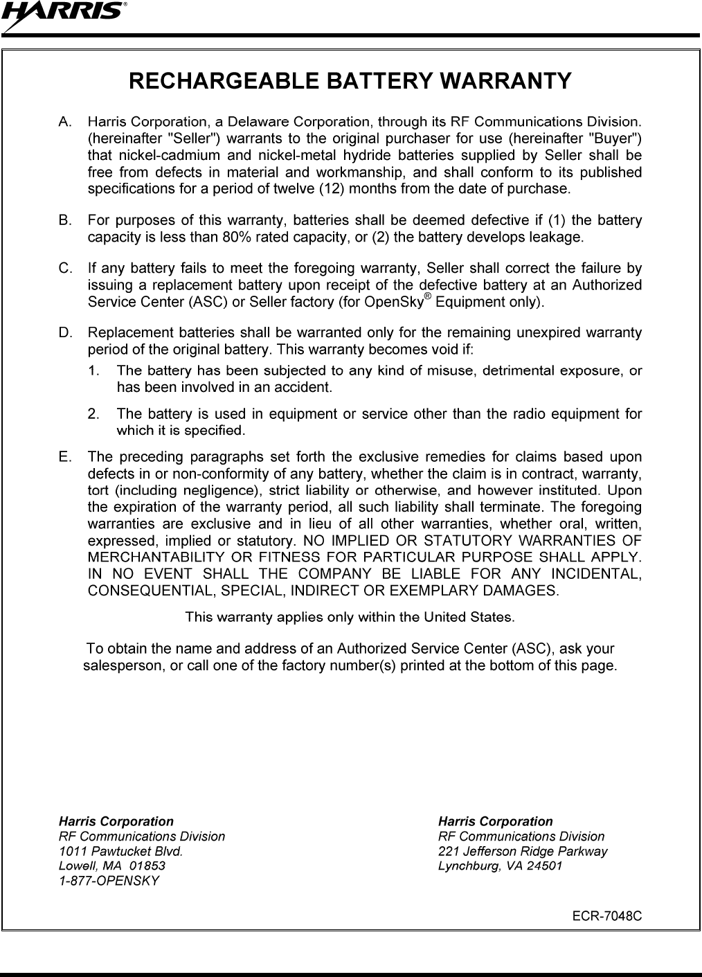
MM-013994-001, Rev. Ap1
151
MM-013994-001, Rev. Ap1
152

RF Communications Division | 221 Jefferson Ridge Pkwy. | Lynchburg, VA USA 24501
Tel: 1-800-528-7711 (Outside USA, 1-434-35-2400) www.rfcomm.harris.com