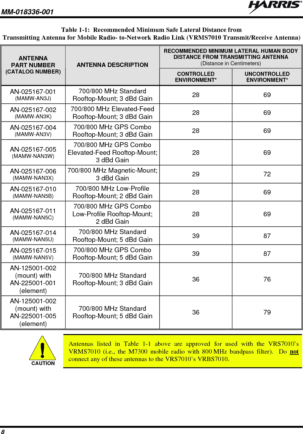
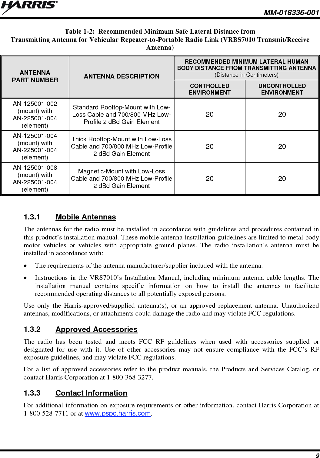
HARRIS TR-0058-E Vehicular Repeater Base System (VRBS) User Manual Manual 1 rev
HARRIS CORPORATION Vehicular Repeater Base System (VRBS) Manual 1 rev
HARRIS >
Contents
- 1. Manual 1 rev
- 2. Manual 2 rev
- 3. User Manual 1
- 4. User Manual 2
Manual 1 rev

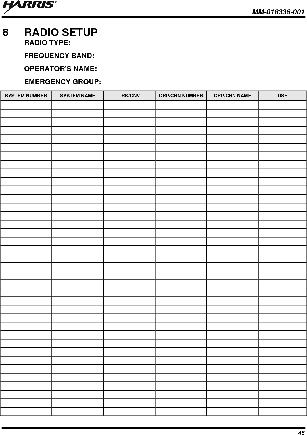
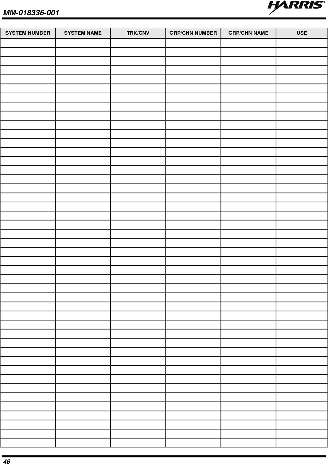
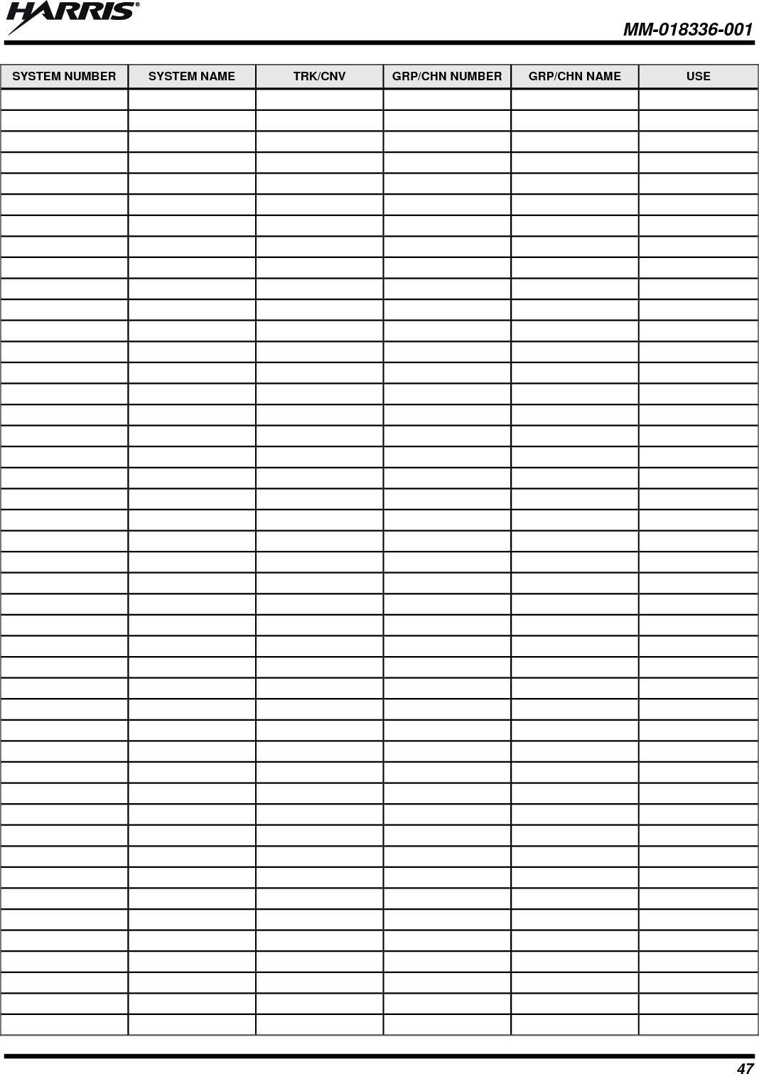
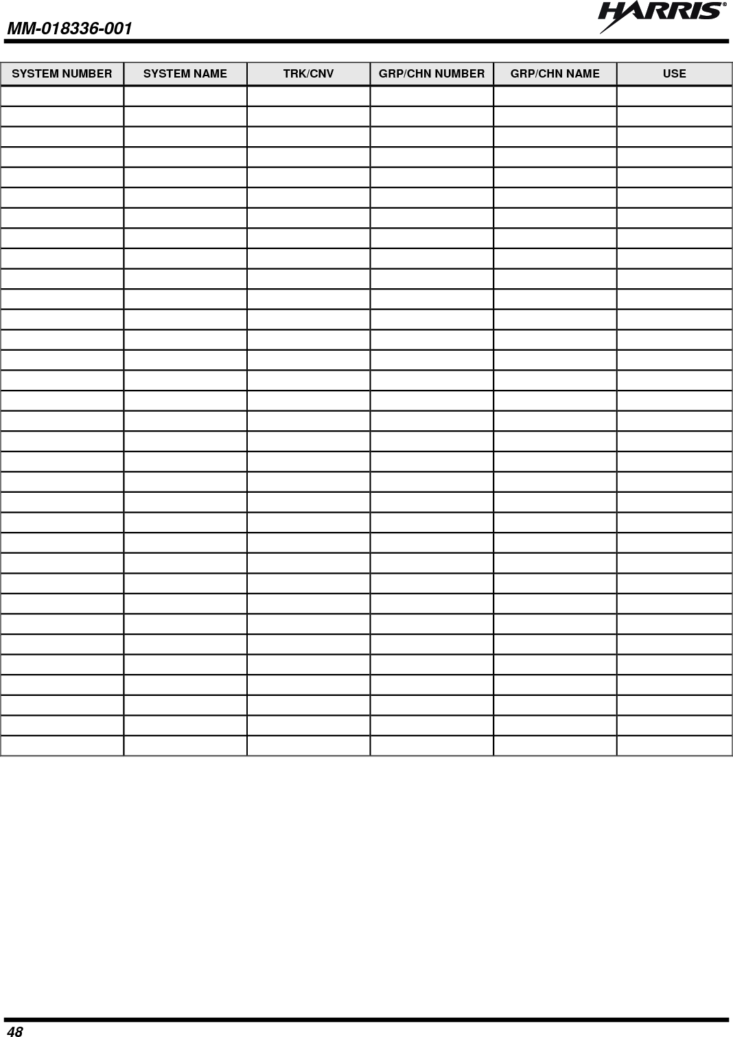
![MM-018336-001 35 radio will transmit an emergency call request with the radio ID until an emergency channel assignment is received. 2. When the working channel assignment is received, the radio sounds a single beep (Autokey alert tone) indicating it is ready for voice transmission. *TXEMER* flashes on line 2 in the display until the emergency is cleared. 3. Press PTT and speak into the microphone in a normal voice. 4. Release PTT when the transmission is complete and listen for a reply. 5. The emergency can be cleared by pressing and holding the CLR button followed by pressing the red Emergency/Home button then releasing both buttons. 5.15 SYSTEM SCAN OPERATION The radio can be programmed with the following system scan features. These features are automatically enabled upon radio power up. A key or menu option is also defined to allow the system scan features to be toggled during radio operation. This is covered in the Menu Selection and Pre-Programmed Keypad Key sections. The system scan state will be maintained through system changes but will default to on at power up. 5.15.1 Wide Area System Scan The mobile radio can be programmed for wide area system scan operation. Upon the loss of the currently selected system’s control channel, radios can be programmed to automatically scan the control channels of other systems. If a new control channel is found, the radio will switch to the new system and sound an alert tone. 5.15.2 ProScan™ The radio can be programmed for ProScan™ system scan operation for multi-site applications depending on the version of radio flash code. ProScan provides the radio with the ability to select a new system for the radio to communicate on, when the selected system drops below a predefined level. This is accomplished by enabling each radio to analyze the signal quality of its current control channel and compare it with the signal quality of the control channel for each site in its adjacency scan list. The signal quality metric used for the ProScan algorithm is based on a combination of both Received Signal Strength Indicator [RSSI] and Control Channel Verification [CCV] measurements. When the selected system’s signal quality level degrades below a pre-programmed level, the radio will begin to look for a better control channel. Once a control channel that exceeds the pre-programmed parameters is found, the radio will change to the new system and emit a tone. If the control channel is completely lost, the radio enters Wide Area System Scanning and search the programmed adjacent systems until a suitable control channel is found. 5.15.3 Priority System Scan The radio can also be programmed for Priority System Scan. (To ensure that this feature operates correctly, the control channel of the priority system must be located on channel one unless you are using the ProScan algorithm.) The priority system is the desired or preferred system. While receiving the control channel of the selected system, the radio will periodically leave the selected system and search for the control channel of the priority system at a programmable rate. The programmable rate is defined by the value in the Priority Scan Time control, (unless the ProScan algorithm is enabled as explained below). This priority scan timer is reset each time the PTT button is pressed or when a call is received. If the priority system control channel is found, or meets the predefined ProScan criteria, the radio will automatically switch to the priority system.](https://usermanual.wiki/HARRIS/TR-0058-E.Manual-1-rev/User-Guide-1240267-Page-35.png)