HARRIS TR-0058-E Vehicular Repeater Base System (VRBS) User Manual Manual 2 rev
HARRIS CORPORATION Vehicular Repeater Base System (VRBS) Manual 2 rev
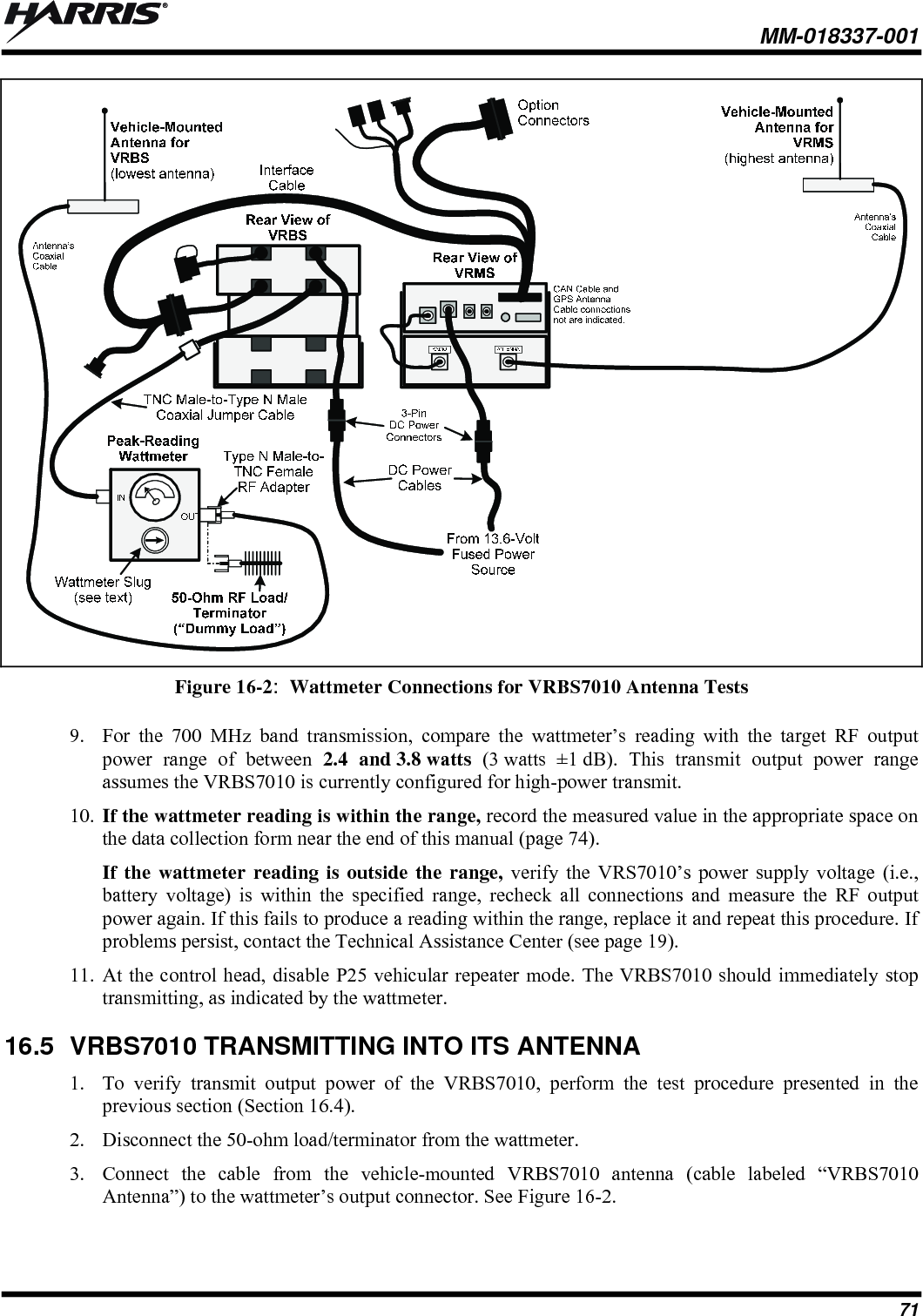
HARRIS >
Contents
- 1. Manual 1 rev
- 2. Manual 2 rev
- 3. User Manual 1
- 4. User Manual 2
Manual 2 rev

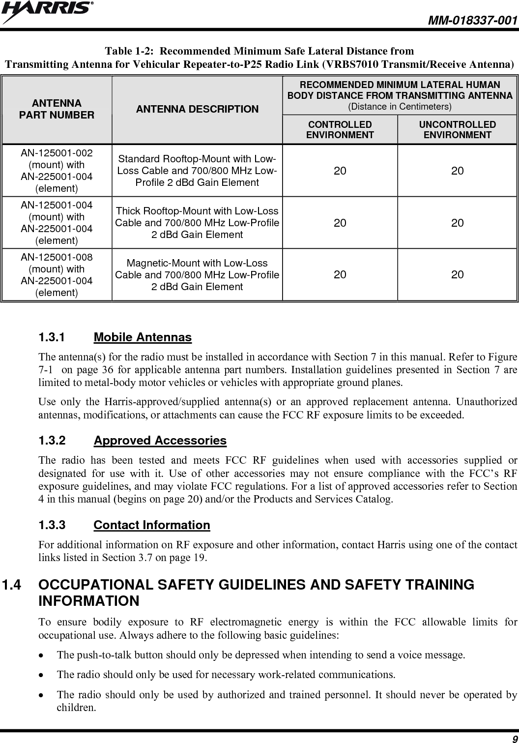
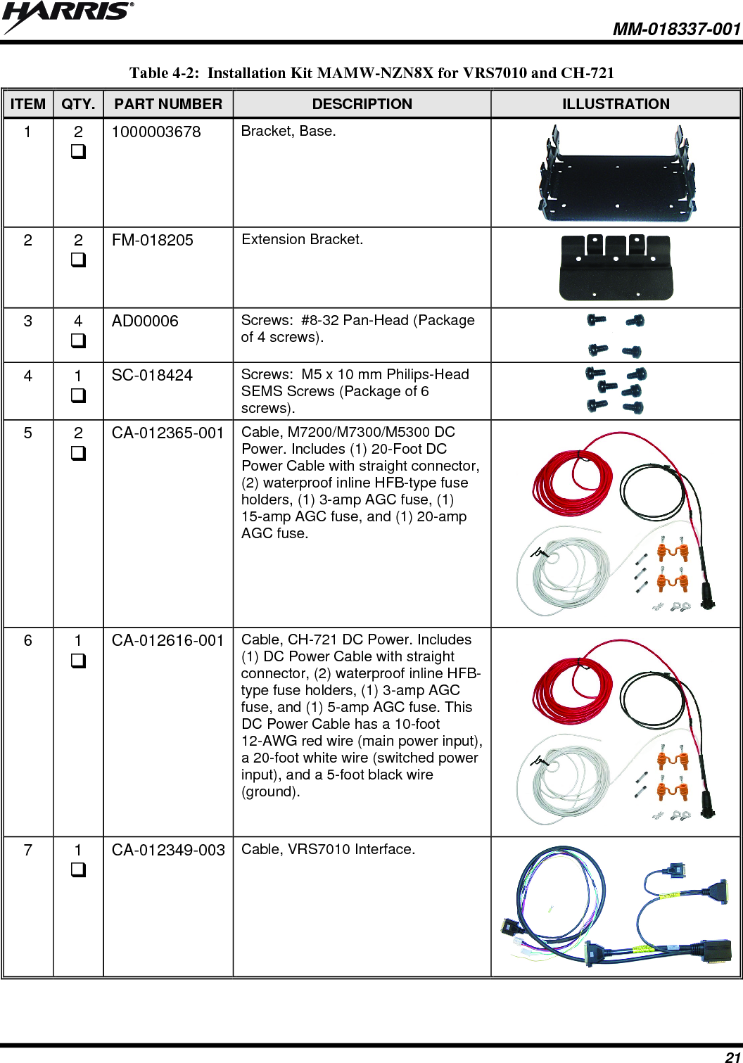
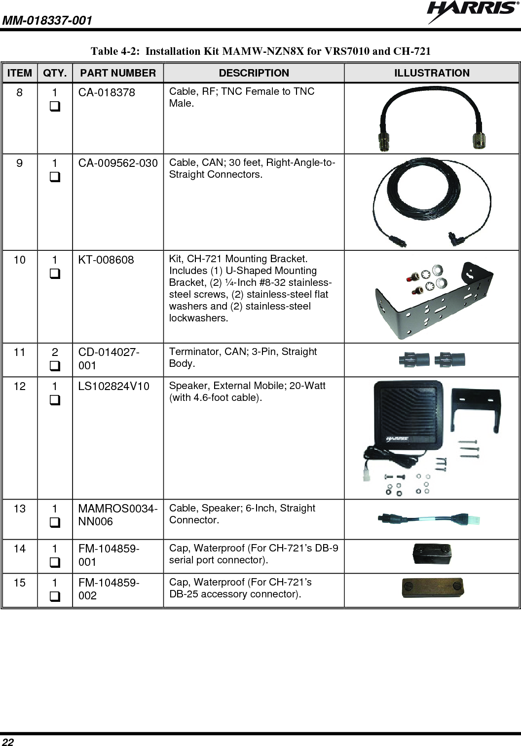
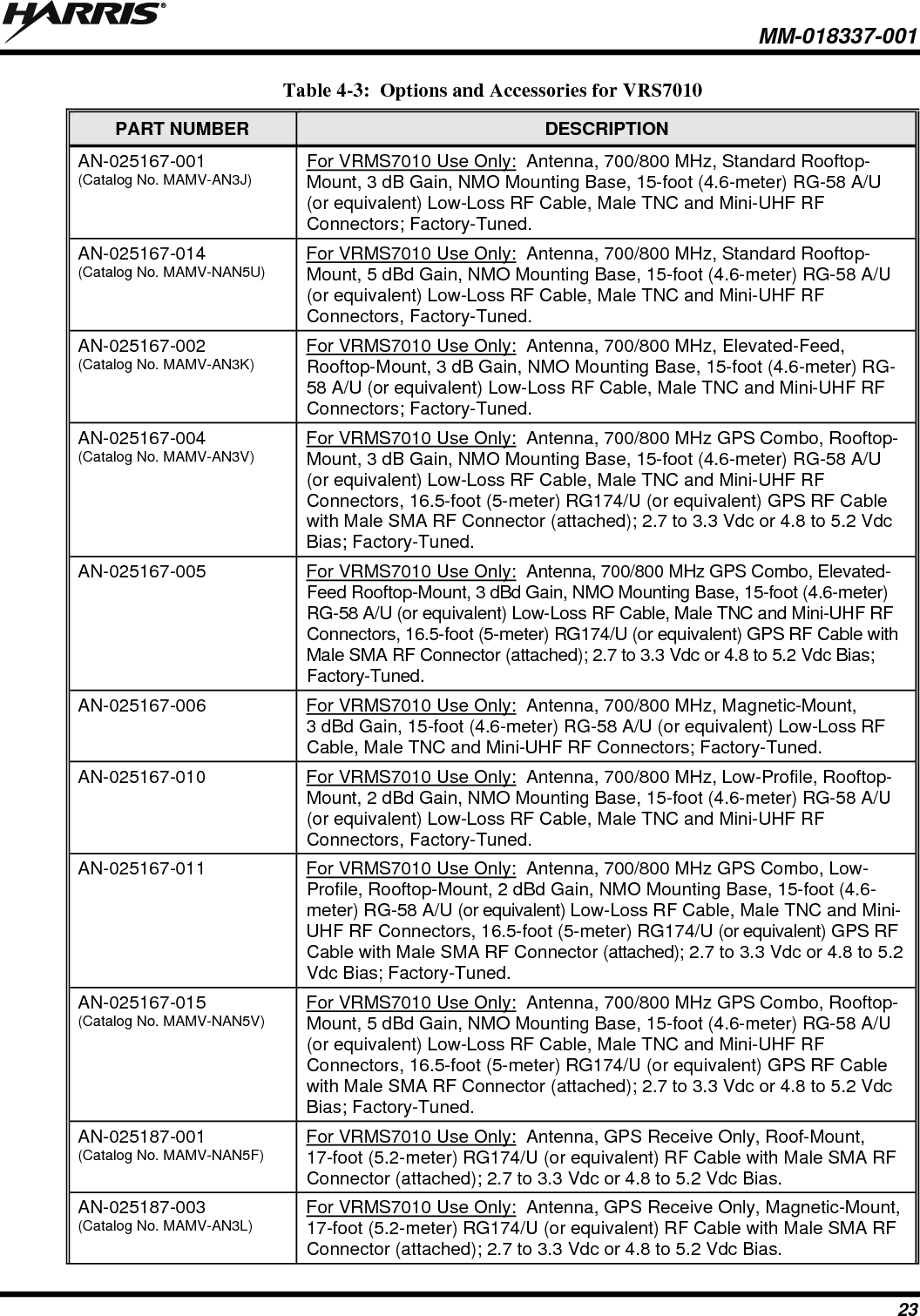
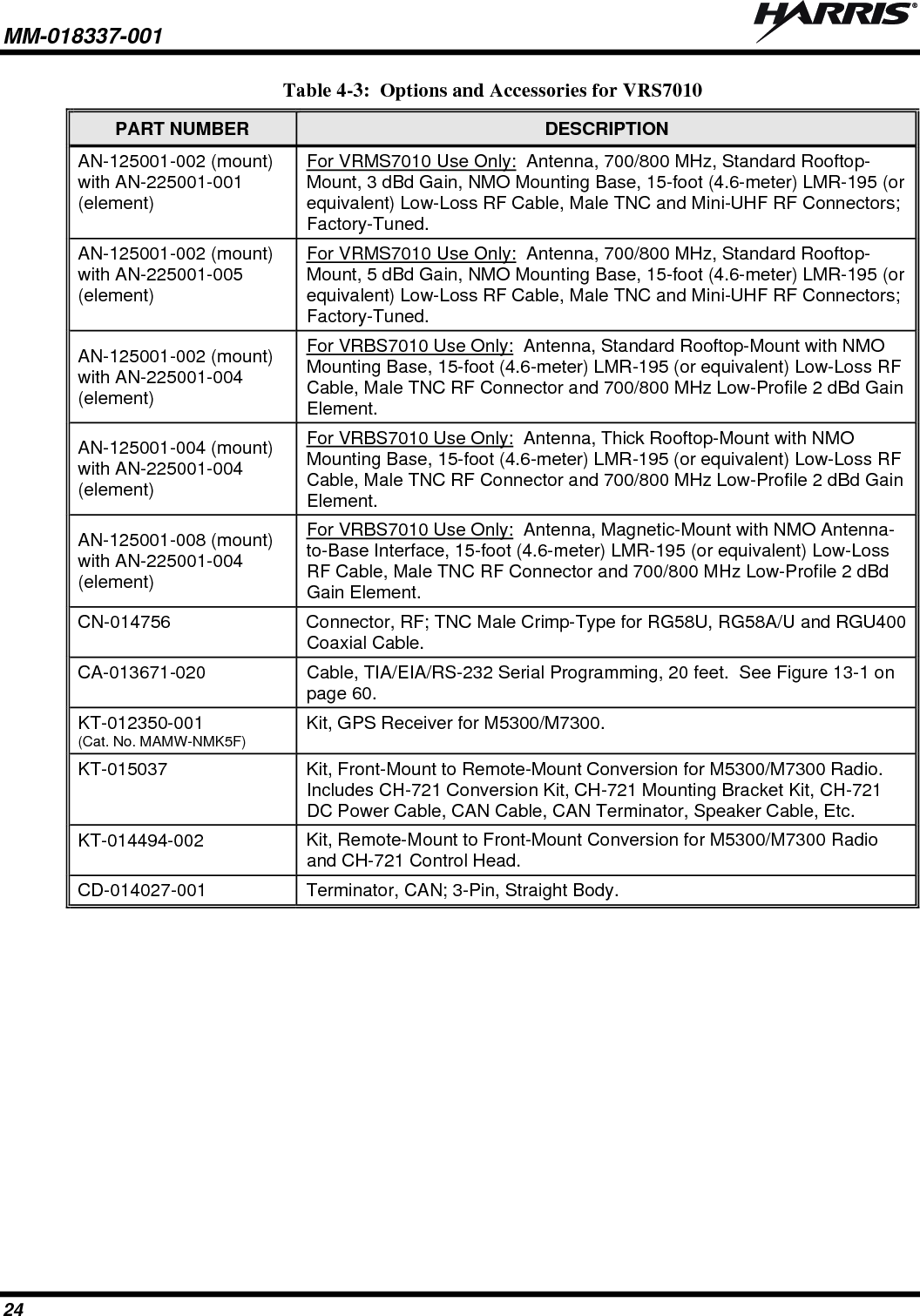
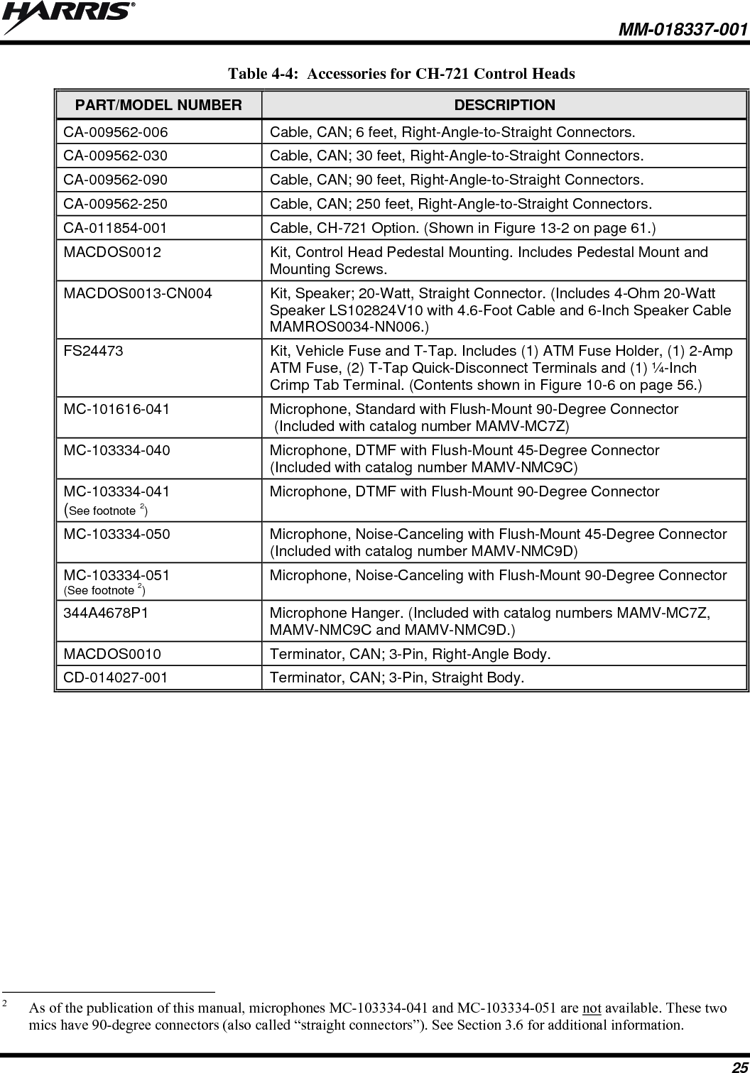
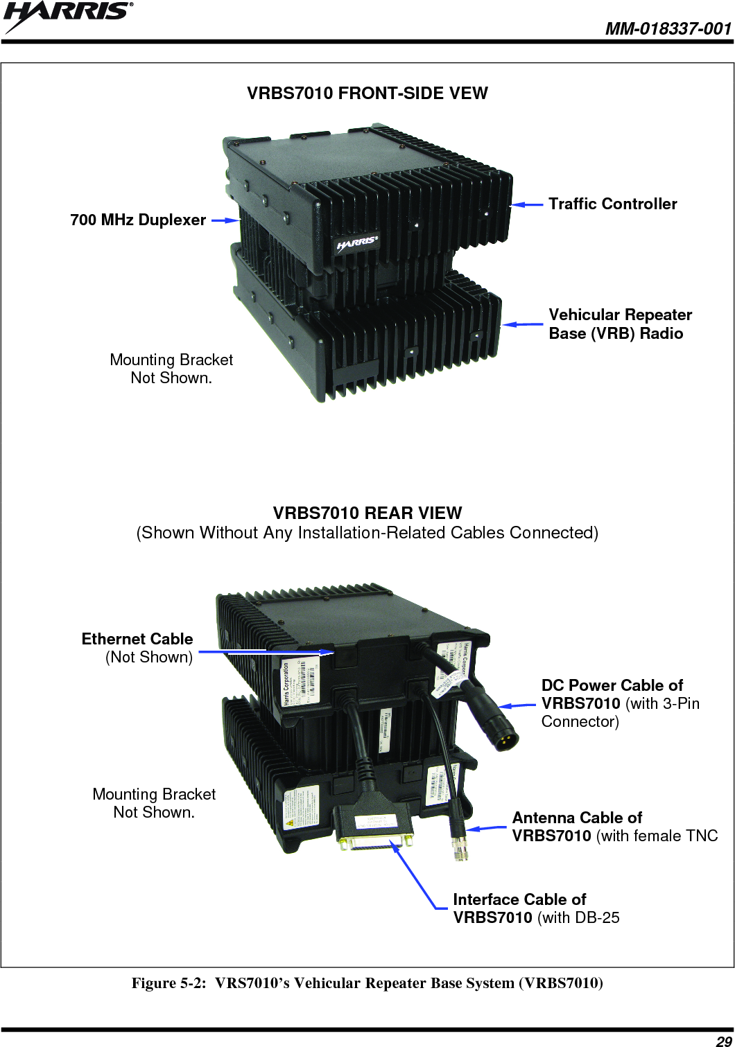
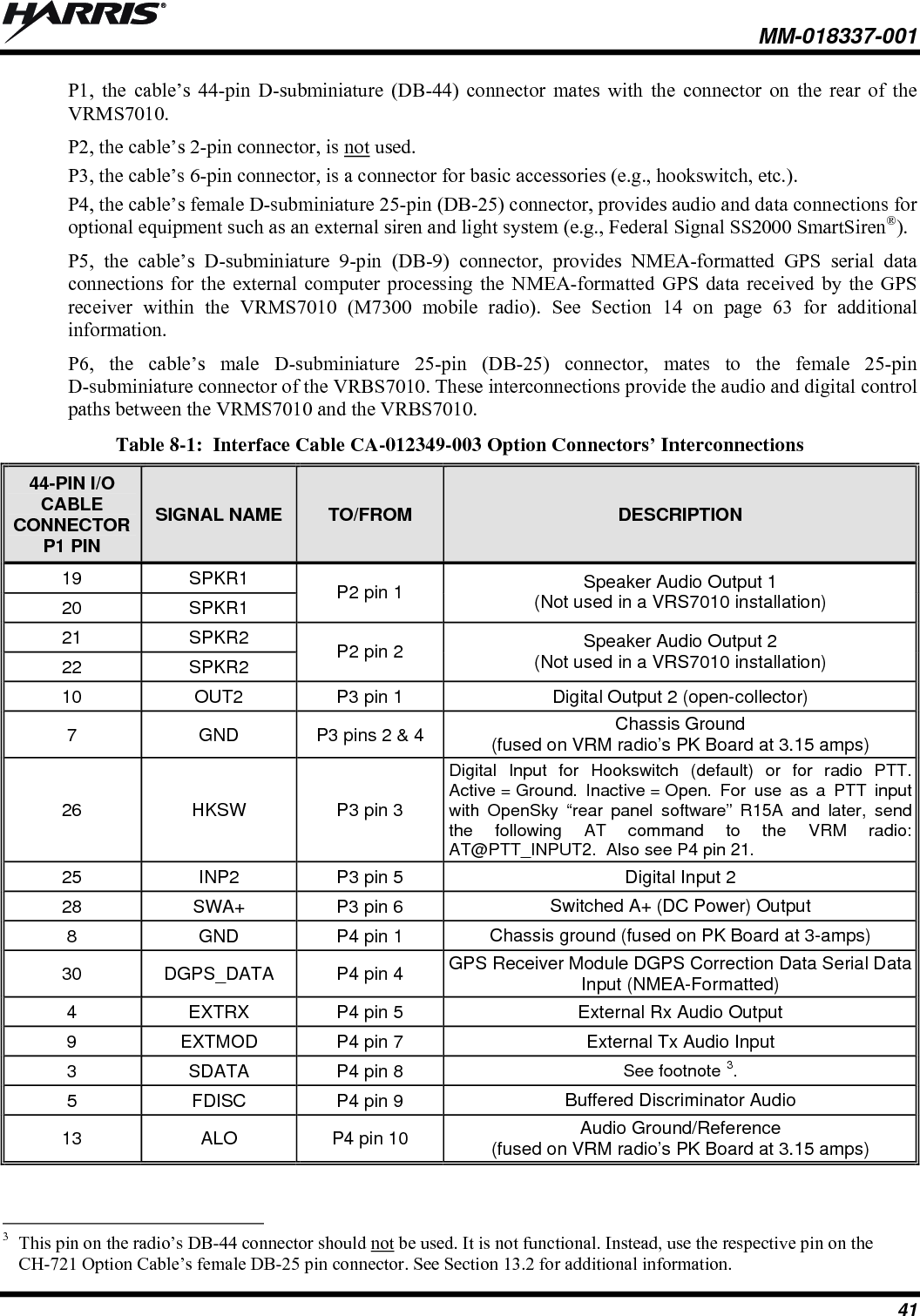
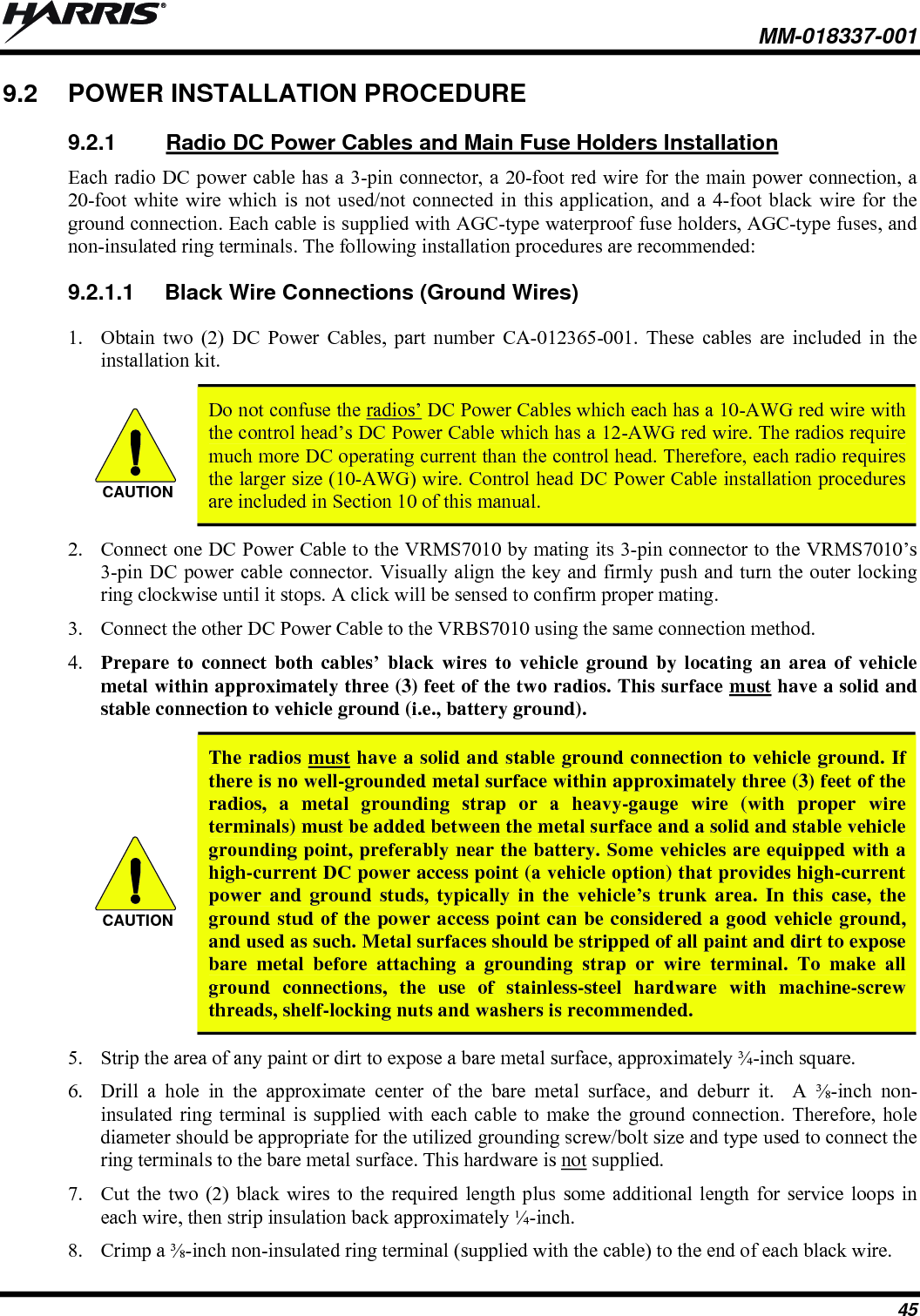
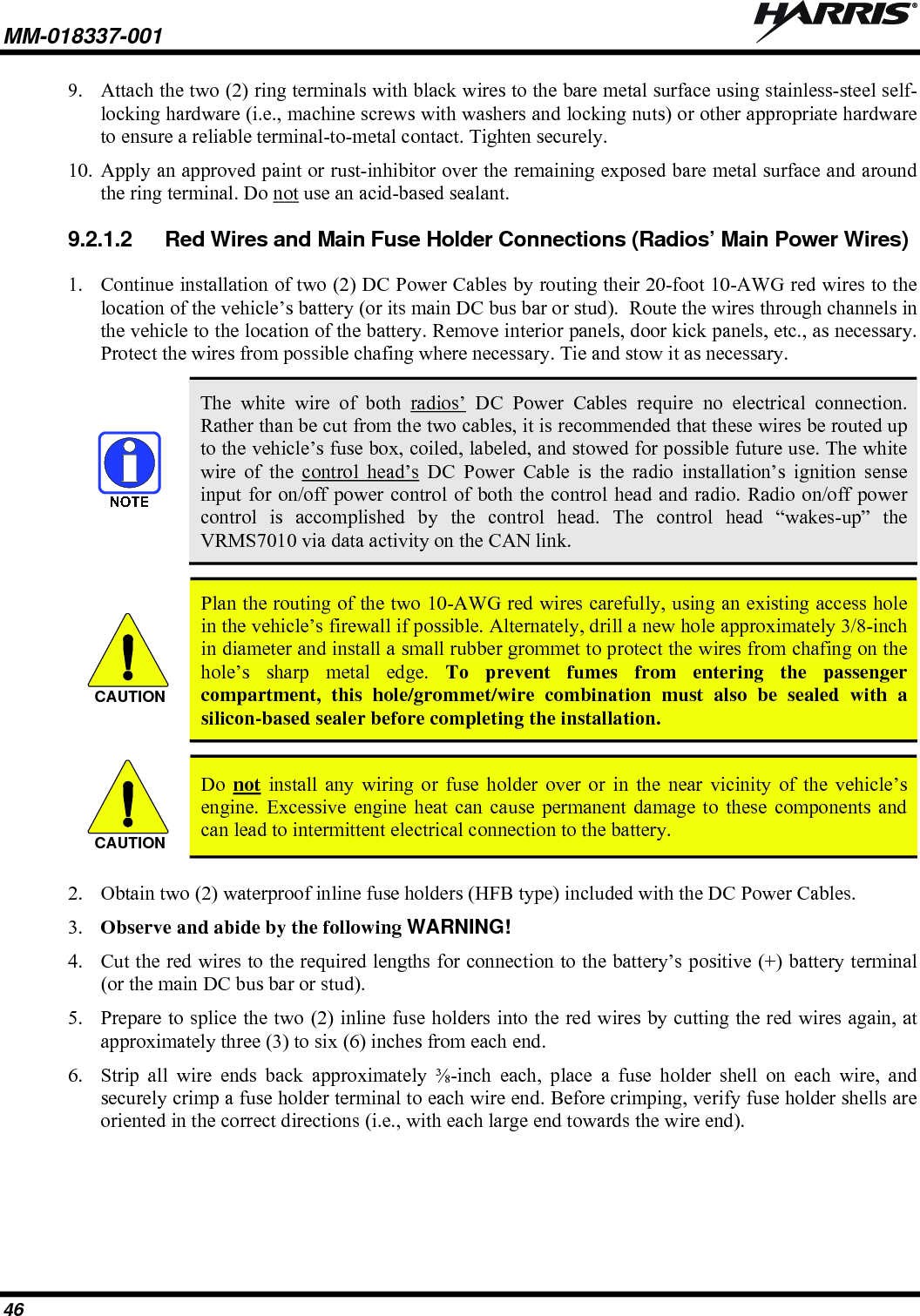
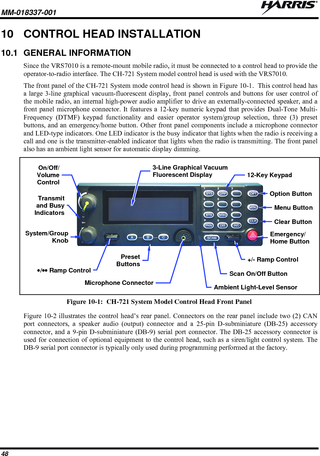
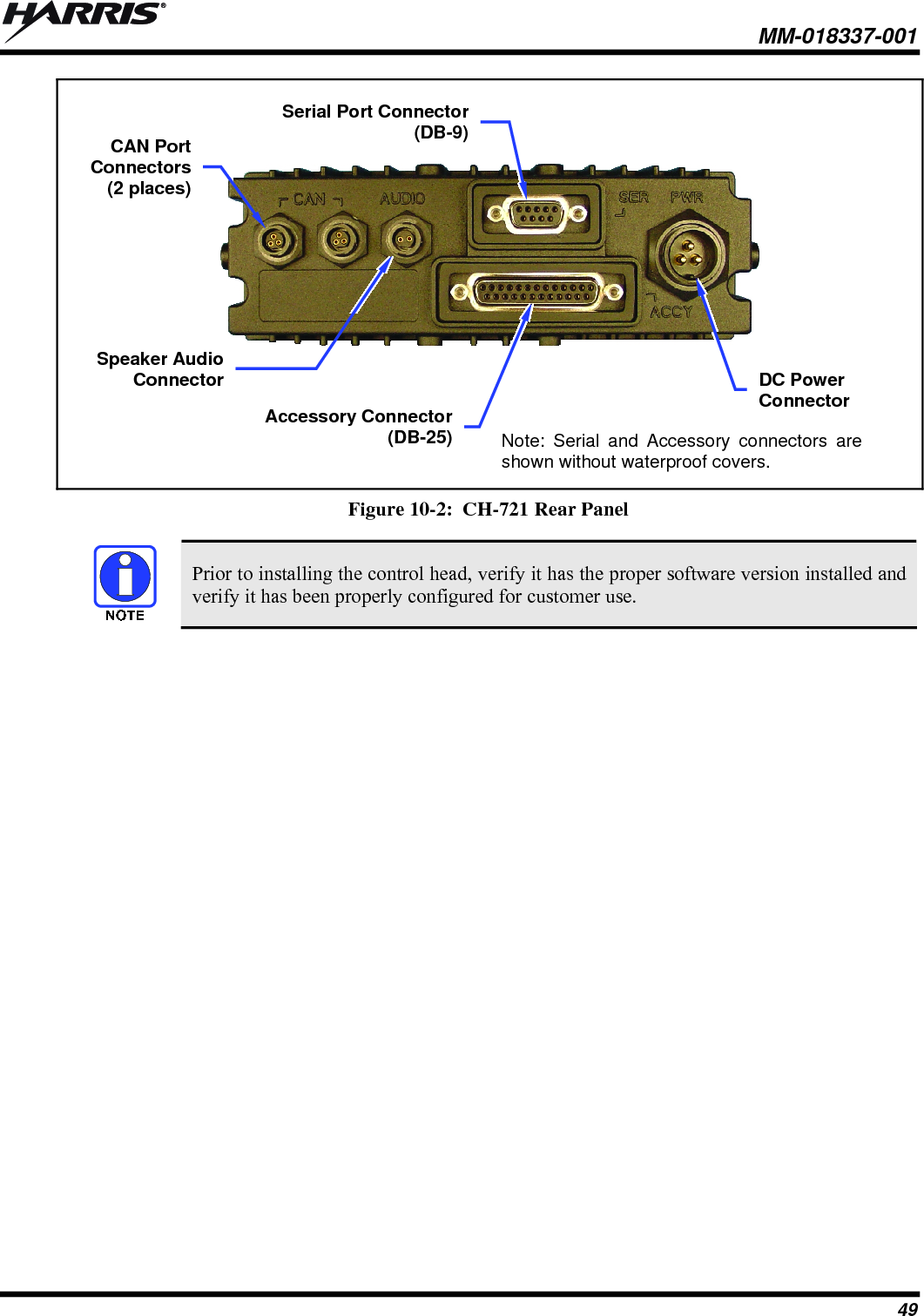
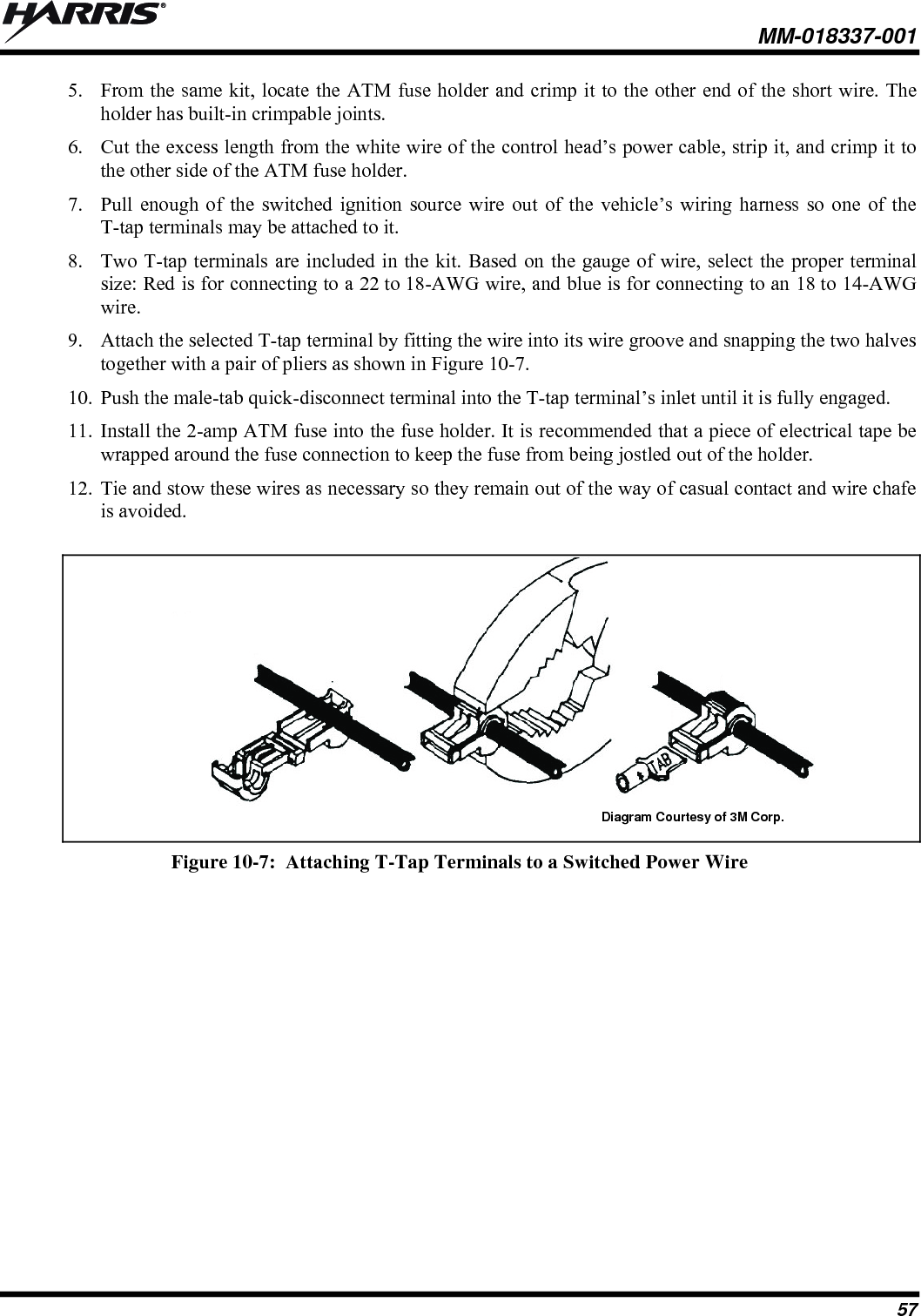
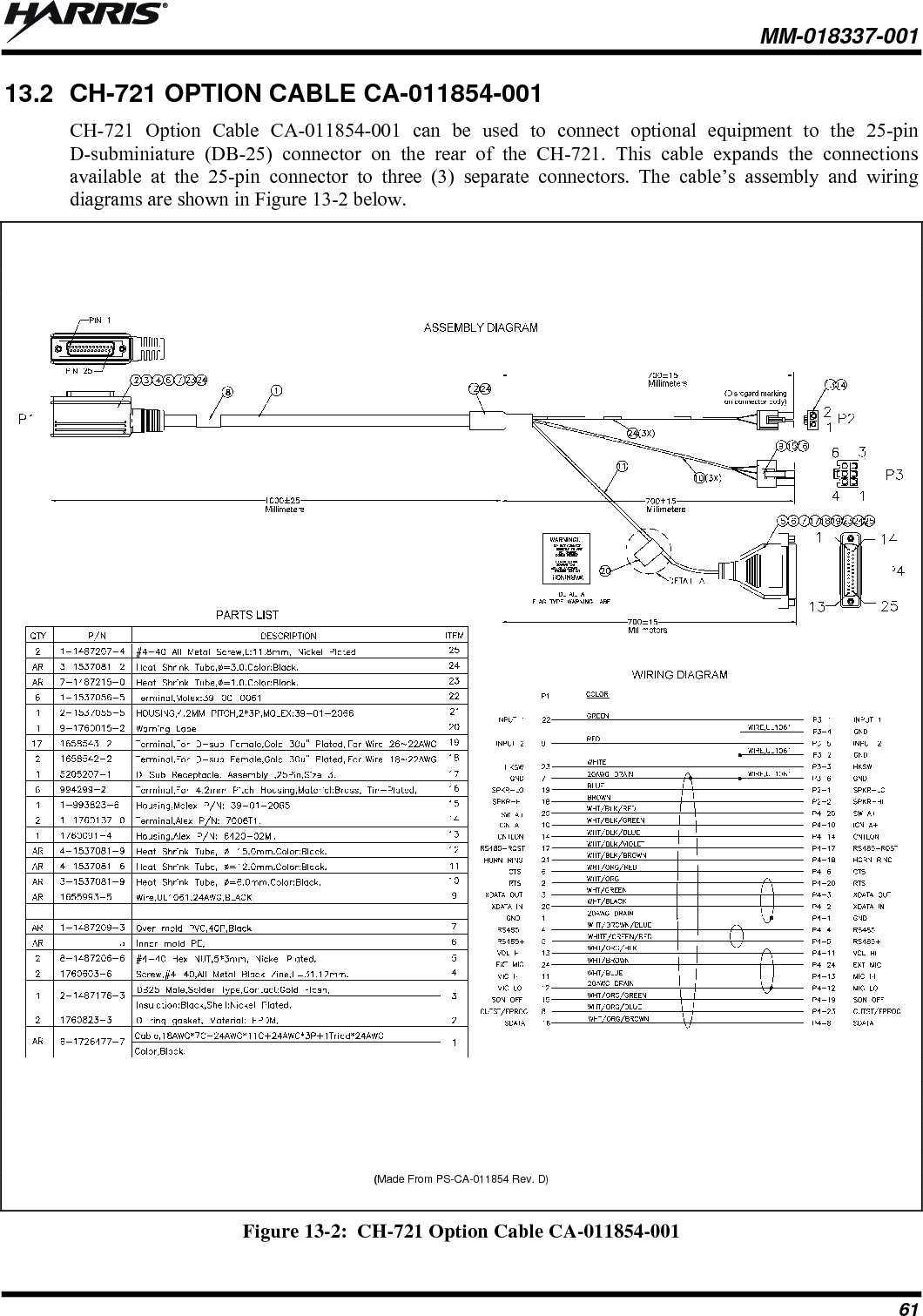
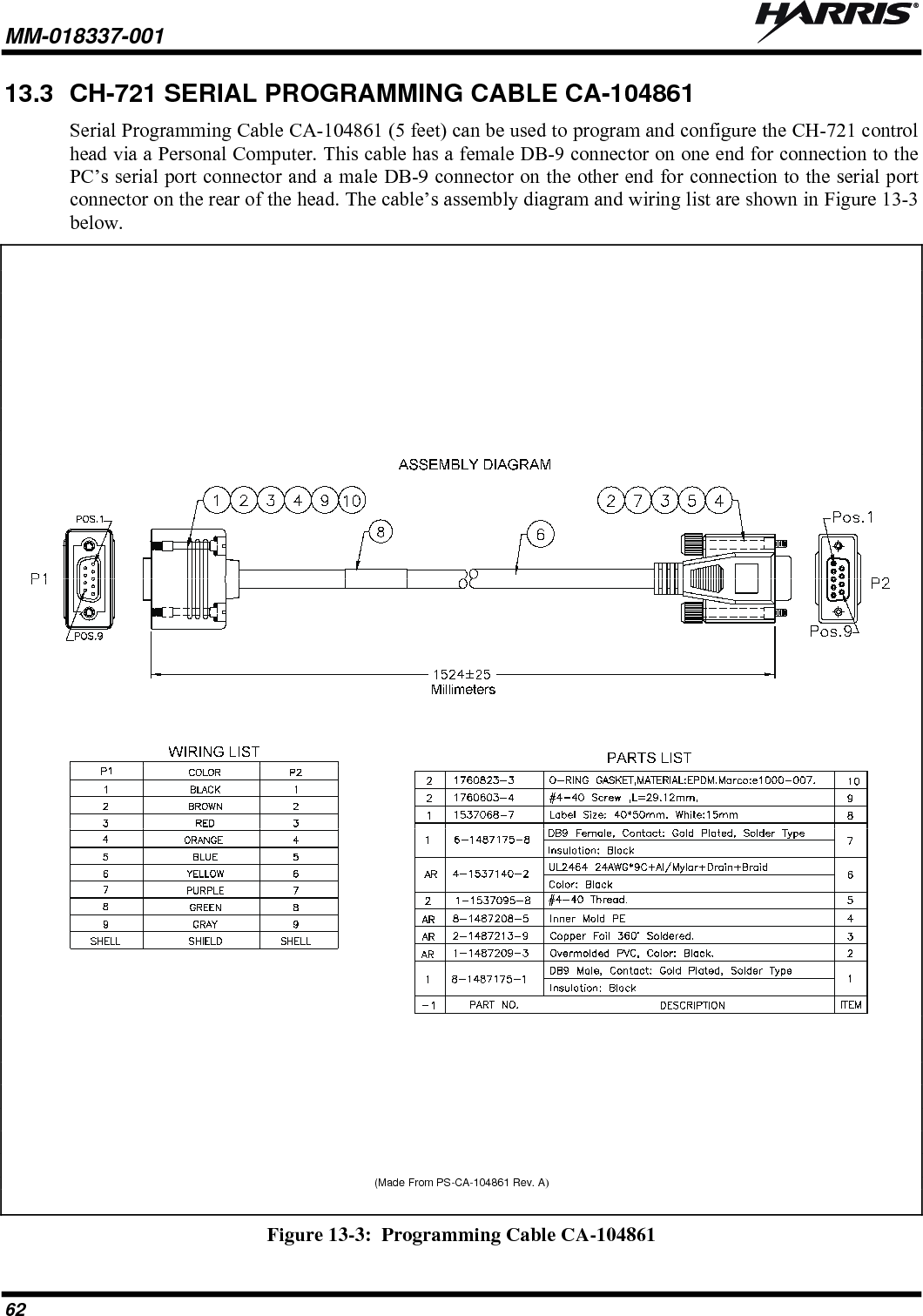
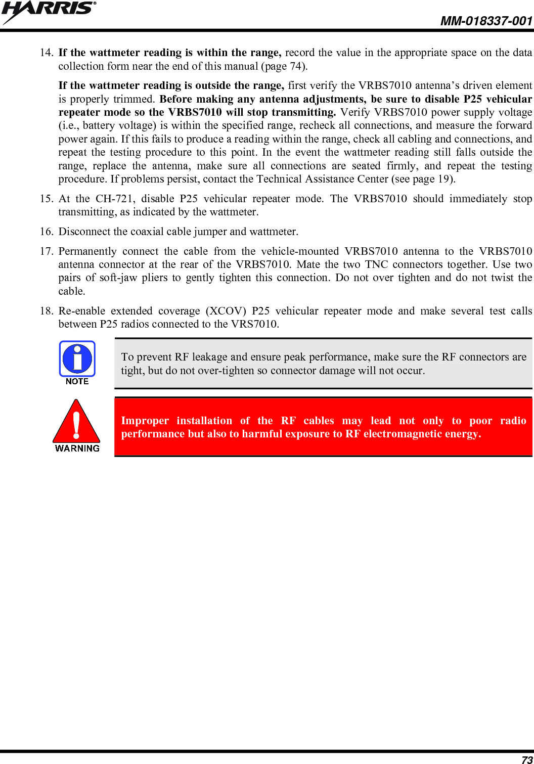
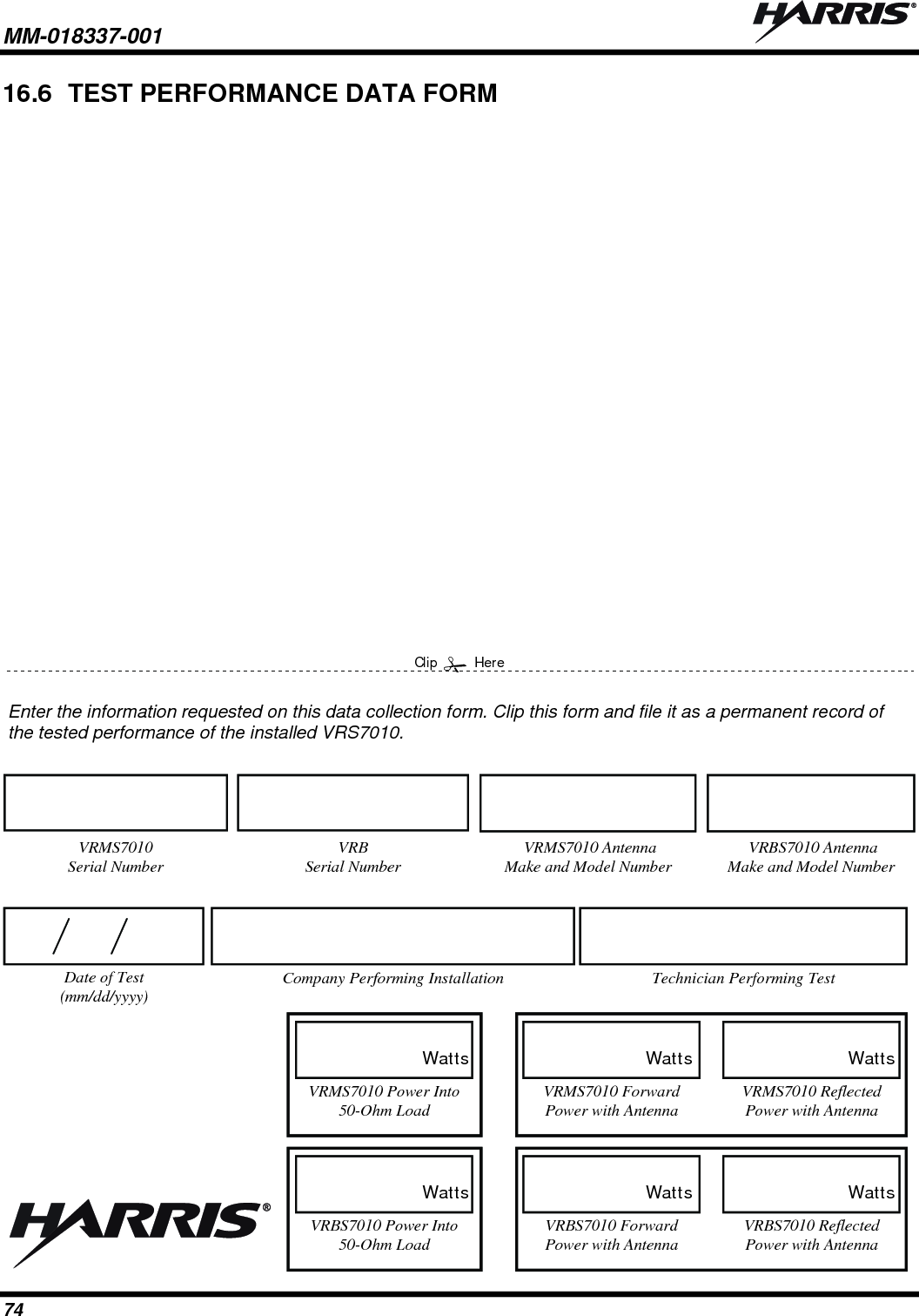
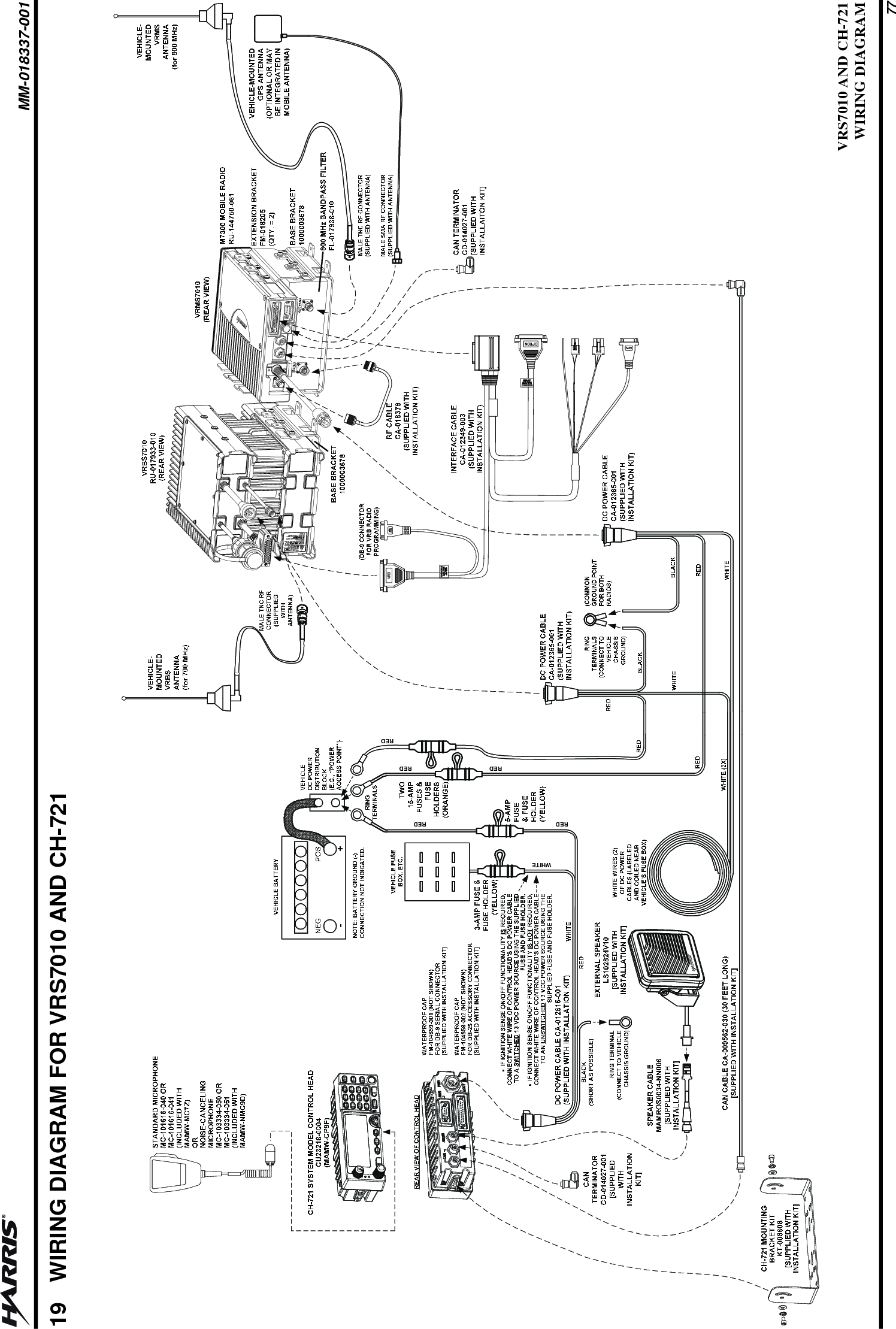
![MM-018337-001 20 4 UNPACKING AND CHECKING THE EQUIPMENT 4.1 MATERIALS A typical set of VRS7010 installation materials includes: VRS7010 Vehicular Repeater Mobile System (VRMS7010), consists of: M7300 Remote-Mount Mobile Radio [See Table 4-1 below for part and catalog number] VRS7010 VRM 800 MHz Bandpass Filter [See Table 4-1 below for part and catalog number] VRS7010 Vehicular Repeater Base System (VRBS7010) [See Table 4-1 below for part and catalog number] CH-721 System Control Head [part number CU23218-0004; catalog number MAMW-CP9F] Standard Microphone [part number MC-101616-041; part of catalog number MAMW-MC7Z] Installation Kit MAMW-NZN8X for VRS7010 and CH-721 as listed in Table 4-2 Two (2) or Three (3) Antennas as listed in Table 4-3 Table 4-1: VRS7010 Catalog and Part Numbers CATALOG NUMBER PART NUMBER DESCRIPTION MAMW-SDMXX RU-144750-061 Remote-Mount Dual-Band 700/800 MHz M7300 Mobile Radio (VRM Radio of VRMS7010) MAMW-NFL1A FL-017938-010 800 MHz Bandpass Filter (Bandpass Filter of VRMS7010) MAMW-VDLXX RU-017933-010 VRBS7010 The Installation Kit can be used to install the VRS7010, or individual components may be purchased separately as needed. Table 4-2 lists the parts included in the kit. Table 4-3 lists part numbers for radio options and accessories. Table 4-4 includes optional parts available for the CH-721 control head.](https://usermanual.wiki/HARRIS/TR-0058-E.Manual-2-rev/User-Guide-1240268-Page-20.png)