HARRIS TR-0058-E Vehicular Repeater Base System (VRBS) User Manual Manual 2 rev
HARRIS CORPORATION Vehicular Repeater Base System (VRBS) Manual 2 rev
HARRIS >
Contents
- 1. Manual 1 rev
- 2. Manual 2 rev
- 3. User Manual 1
- 4. User Manual 2
Manual 2 rev

Installation and Product Safety Manual
MM-018337-001
Feb/10
r
VRS7010
P25 Trunked Cross-Band
Vehicular Repeater System
Includes
VRBS7010 for Vehicular Repeater Link,
VRMS7010 for Network Link,
and CH-721 Control Head
MM-018337-001
2
MANUAL REVISION HISTORY
REV. DATE REASON FOR CHANGE
– Feb/10 Initial release.
Harris Corporation, Public Safety and Professional Communications (PS&PC) Business, continually evaluates its technical
publications for completeness, technical accuracy, and organization. You can assist in this process by submitting your
comments and suggestions to the following:
Harris Corporation fax your comments to: 1-434-455-6851
PS&PC Business or
Technical Publications e-mail us at: PSPC_TechPubs@harris.com
221 Jefferson Ridge Parkway
Lynchburg, VA 24501 ACKNOWLEDGEMENT
This device is made under license under one or more of the following US patents: 4,590,473; 4,636,791; 5,148,482;
5,185,796; 5,271,017; 5,377,229; 4,716,407; 4,972,460; 5,502,767; 5,146,497; 5,164,986; 5,185,795; 5,226,084; 5,247,579;
5,491,772; 5,517,511; 5,630,011; 5,649,050; 5,701,390; 5,715,365; 5,754,974; 5,826,222; 5,870,405; 6,161,089; and
6,199,037 B1. DVSI claims certain rights, including patent rights under aforementioned U.S. patents, and under other U.S.
and foreign patents and patents pending. Any use of this software or technology requires a separate written license from
DVSI. CREDITS
Harris and assuredcommunications are registered trademarks of Harris Corporation.
All other brand and product names are trademarks, registered trademarks, or service marks of their respective holders.
NOTICE!
Information and descriptions contained herein are the property of Harris Corporation. Such information and descriptions may
not be copied or reproduced by any means, or disseminated or distributed without the express prior written permission of
Harris Corporation, PS&PC Business, 221 Jefferson Ridge Parkway, Lynchburg, VA 24501.
Repairs to this equipment should be made only by an authorized service technician or facility designated by the supplier. Any
repairs, alterations or substitutions of recommended parts made by the user to this equipment not approved by the
manufacturer could void the user's authority to operate the equipment in addition to the manufacturer's warranty.
This product conforms to the European Union WEEE Directive 2002/96/EC. Do not dispose of this product in a
public landfill. Take it to a recycling center at the end of its life.
This manual is published by Harris Corporation without any warranty. Improvements and changes to this manual
necessitated by typographical errors, inaccuracies of current information, or improvements to programs and/or equipment,
may be made by Harris Corporation at any time and without notice. Such changes will be incorporated into new editions o
f
this manual. No part of this manual may be reproduced or transmitted in any form or by any means, electronic or mechanical,
including photocopying and recording, for any purpose, without the express written permission of Harris Corporation.
Copyright © 2010, Harris Corporation.

MM-018337-001
3
TABLE OF CONTENTS
Section Page
1 REGULATORY AND SAFETY INFORMATION ...................................................................................6
1.1 SAFETY SYMBOL CONVENTIONS.................................................................................................6
1.2 RF ENERGY EXPOSURE AWARENESS AND CONTROL INFORMATION FOR FCC
OCCUPATIONAL USE REQUIREMENTS........................................................................................ 6
1.2.1 Federal Communications Commission Regulations...............................................................7
1.3 COMPLIANCE WITH RF EXPOSURE STANDARDS...................................................................... 7
1.3.1 Mobile Antennas ....................................................................................................................9
1.3.2 Approved Accessories............................................................................................................9
1.3.3 Contact Information................................................................................................................9
1.4 OCCUPATIONAL SAFETY GUIDELINES AND SAFETY TRAINING INFORMATION .............9
1.5 COMMON HAZARDS ......................................................................................................................10
1.6 SAFE DRIVING RECOMMENDATIONS........................................................................................ 11
1.7 OPERATING RULES REGULATIONS............................................................................................11
1.8 OPERATING TIPS.............................................................................................................................12
2 SPECIFICATIONS.....................................................................................................................................13
2.1 GENERAL.......................................................................................................................................... 13
2.2 REGULATORY .................................................................................................................................14
3 INTRODUCTION.......................................................................................................................................15
3.1 GENERAL INFORMATION .............................................................................................................15
3.1.1 Vehicular Repeater Base System (VRBS7010)....................................................................15
3.1.2 Vehicular Repeater Mobile System (VRMS7010) ............................................................... 15
3.2 OPERATING MODES .......................................................................................................................16
3.2.1 Standard Mobile Radio Mode...............................................................................................16
3.2.2 Extended Coverage (XCOV) Vehicular Repeater Mode......................................................16
3.3 EQUIPMENT MOUNTING AND CONTROL HEAD ......................................................................17
3.4 OPERATING POWER .......................................................................................................................18
3.5 RELATED PUBLICATIONS.............................................................................................................19
3.6 REPLACEMENT PARTS ..................................................................................................................19
3.7 TECHNICAL ASSISTANCE............................................................................................................. 19
4 UNPACKING AND CHECKING THE EQUIPMENT...........................................................................20
4.1 MATERIALS......................................................................................................................................20
4.2 MATERIAL INSPECTION................................................................................................................26
5 PLANNING THE INSTALLATION.........................................................................................................27
5.1 GENERAL INFORMATION .............................................................................................................27
5.2 TOOLS REQUIRED...........................................................................................................................27
5.3 LOCATING COMPONENTS ............................................................................................................30
6 MOUNTING THE VRS7010’S VRMS7010 AND VRBS7010 ................................................................31
6.1 INSTALL THE MOUNTING BRACKETS .......................................................................................31
6.2 MOUNT THE RADIOS AND FILTER INTO THE BRACKETS...................................................... 33
7 ANTENNA INSTALLATION ...................................................................................................................35
7.1 ANTENNA MOUNTING LOCATIONS ........................................................................................... 35
7.1.1 Direct Center or Center-Rear of Rooftop for VRMS7010 Antenna ..................................... 35
7.1.2 Center of Trunk Lid for VRBS7010 Antenna ...................................................................... 35
7.1.3 Rear Deck Lid for GPS Stand-Alone GPS Receive Antenna ...............................................37
7.2 ANTENNA INSTALLATION PROCEDURE ...................................................................................37
7.2.1 Install and Connect Mobile Antennas................................................................................... 37
7.2.2 Connect RF Cable Between VRM Radio and 800 MHz Bandpass Filter.............................38
7.2.3 Install and Connect GPS Antenna (If Required) ..................................................................38
8 INTERFACE CABLE INSTALLATION.................................................................................................40

MM-018337-001
4
(Continued)
TABLE OF CONTENTS
Section Page
8.1 INTERFACE CABLE CA-012349-003 OVERVIEW ........................................................................40
8.2 INTERFACE CABLE CA-012349-003 INSTALLATION PROCEDURE ........................................42
9 DC POWER INSTALLATION..................................................................................................................44
9.1 OVERVIEW OF ON/OFF POWER WIRING CONFIGURATIONS.................................................44
9.2 POWER INSTALLATION PROCEDURE.........................................................................................45
9.2.1 Radio DC Power Cables and Main Fuse Holders Installation ..............................................45
10 CONTROL HEAD INSTALLATION.......................................................................................................48
10.1 GENERAL INFORMATION .............................................................................................................48
10.2 CONTROL HEAD MECHANICAL INSTALLATION .....................................................................50
10.2.1 Selecting the Mounting Location..........................................................................................50
10.2.2 Using the Standard U-Shaped Mounting Bracket.................................................................51
10.2.3 Using the Mounting Pedestal (Optional) ..............................................................................51
10.3 CAN CONNECTIONS .......................................................................................................................52
10.3.1 General Information..............................................................................................................52
10.3.2 Make CAN Link Terminations and Cable Connection.........................................................52
10.4 CONTROL HEAD POWER CABLE INSTALLATION....................................................................53
10.4.1 Install DC Power Cable and Make Power and Ground Connections....................................53
10.4.2 Connect DC Power Cable’s White Wire...............................................................................54
10.4.3 Using Vehicle Fuse and T-Tap Kit (Optional) Instead of Waterproof Inline Fuse Holder
(Standard) .............................................................................................................................56
11 SPEAKER INSTALLATION.....................................................................................................................58
12 MICROPHONE ATTACHMENT.............................................................................................................59
13 OPTIONAL CABLES.................................................................................................................................60
13.1 SERIAL PROGRAMMING CABLE CA-013671-020 .......................................................................60
13.2 CH-721 OPTION CABLE CA-011854-001........................................................................................61
13.3 CH-721 SERIAL PROGRAMMING CABLE CA-104861.................................................................62
14 GPS NMEA-FORMATTED SERIAL DATA CONNECTION...............................................................63
15 INITIAL POWER-UP TEST .....................................................................................................................64
16 PERFORMANCE TESTS..........................................................................................................................65
16.1 REQUIRED TEST EQUIPMENT ......................................................................................................66
16.2 VRMS7010 TRANSMITTING INTO A 50-OHM LOAD/TERMINATOR.......................................66
16.3 VRMS7010 TRANSMITTING INTO ITS ANTENNA......................................................................68
16.4 VRBS7010 TRANSMITTING INTO A 50-OHM LOAD/TERMINATOR .......................................70
16.5 VRBS7010 TRANSMITTING INTO ITS ANTENNA.......................................................................71
16.6 TEST PERFORMANCE DATA FORM .............................................................................................74
17 COMPLETE THE INSTALLATION .......................................................................................................75
18 WARRANTY...............................................................................................................................................76
19 WIRING DIAGRAM FOR VRS7010 AND CH-721................................................................................77

MM-018337-001
5
LIST OF FIGURES
Figure Page
Figure 3-1: Simplified Radio-to-Network Block Diagram with VRS7010.........................................................15
Figure 5-1: VRS7010’s Vehicular Repeater Mobile System (VRMS7010)........................................................ 28
Figure 5-2: VRS7010’s Vehicular Repeater Base System (VRBS7010) ............................................................29
Figure 6-1: Base Bracket (Two Required Per VRS7010 Installation).................................................................32
Figure 7-1: Required Antenna Mounting Locations with Antenna Part Numbers ..............................................36
Figure 7-2: Crimping Instructions for TNC RF Connector (Actual Size; Dimensions in Inches)....................... 38
Figure 8-1: Interface Cable CA-012349-003.......................................................................................................40
Figure 10-1: CH-721 System Model Control Head Front Panel ......................................................................... 48
Figure 10-2: CH-721 Rear Panel.........................................................................................................................49
Figure 10-3: Standard U-Shaped Control Head Mounting Bracket (Kit Part Number KT-008608)................... 50
Figure 10-4: Optional Control Head Mounting Pedestal (Part Number MACDOS0012)................................... 50
Figure 10-5: CAN Cable and Terminator Connections.......................................................................................52
Figure 10-6: Contents of Vehicle Fuse and T-Tap Kit FS24473......................................................................... 56
Figure 10-7: Attaching T-Tap Terminals to a Switched Power Wire..................................................................57
Figure 12-1: Attaching the Microphone to the CH-721 Control Head................................................................ 59
Figure 13-1: Serial Programming Cable CA-013671-020...................................................................................60
Figure 13-2: CH-721 Option Cable CA-011854-001.......................................................................................... 61
Figure 13-3: Programming Cable CA-104861 .................................................................................................... 62
Figure 16-1: Wattmeter Connections for VRMS7010 Antenna Tests.................................................................67
Figure 16-2: Wattmeter Connections for VRBS7010 Antenna Tests .................................................................71
LIST OF TABLES
Table Page
Table 1-1: Recommended Minimum Safe Lateral Distance from Transmitting Antenna for Mobile Radio-
to-Network Radio Link (VRMS7010 Transmit/Receive Antenna) ...............................................8
Table 1-2: Recommended Minimum Safe Lateral Distance from Transmitting Antenna for Vehicular
Repeater-to-P25 Radio Link (VRBS7010 Transmit/Receive Antenna) ........................................9
Table 4-1: VRS7010 Catalog and Part Numbers................................................................................................. 20
Table 4-2: Installation Kit MAMW-NZN8X for VRS7010 and CH-721............................................................ 21
Table 4-3: Options and Accessories for VRS7010.............................................................................................. 23
Table 4-4: Accessories for CH-721 Control Heads............................................................................................. 25
Table 8-1: Interface Cable CA-012349-003 Option Connectors’ Interconnections ............................................41
Table 16-1: Test Equipment Required for Performance Tests ............................................................................66
MM-018337-001
6
1 REGULATORY AND SAFETY INFORMATION
1.1 SAFETY SYMBOL CONVENTIONS
The following conventions are used in this manual to alert the user to general safety precautions that must
be observed during all phases of operation, service, and repair of this product. Failure to comply with
these precautions or with specific warnings elsewhere violates safety standards of design, manufacture,
and intended use of the product. Harris assumes no liability for the customer's failure to comply with
these standards.
The WARNING symbol calls attention to a procedure, practice, or the like, which,
if not correctly performed or adhered to, could result in personal injury. Do not
proceed beyond a WARNING symbol until the conditions identified are fully
understood or met.
CAUTION
The CAUTION symbol calls attention to an operating procedure, practice, or the like,
which, if not performed correctly or adhered to, could result in damage to the
equipment or severely degrade equipment performance.
The NOTE symbol calls attention to supplemental information, which may improve
system performance or clarify a process or procedure.
1.2 RF ENERGY EXPOSURE AWARENESS AND CONTROL
INFORMATION FOR FCC OCCUPATIONAL USE REQUIREMENTS
Before using the mobile two-way radio, read this important RF energy awareness and control
information to ensure compliance with RF exposure guidelines.
This radio is intended for use in occupational/controlled conditions, where users
have full knowledge of their exposure and can exercise control over their exposure
to remain below RF exposure limits. This radio is NOT authorized for general
population, consumer, or any other use.
CAUTION
Changes or modifications not expressly approved by Harris could void the user's
authority to operate the equipment.
This two-way radio uses electromagnetic energy in the radio frequency (RF) spectrum to provide
communications between two or more users over a distance. It uses RF energy or radio waves to send and
receive calls. RF energy is one form of electromagnetic energy. Other forms include, but are not limited
to, electric power, sunlight, and x-rays. RF energy, however, should not be confused with these other
forms of electromagnetic energy, which, when used improperly, can cause biological damage. Very high
levels of x-rays, for example, can damage tissues and genetic material.
Experts in science, engineering, medicine, health, and industry work with organizations to develop
standards for exposure to RF energy. These standards provide recommended levels of RF exposure for
both workers and the general public. These recommended RF exposure levels include substantial margins
of protection. All two-way radios marketed in North America are designed, manufactured, and tested to
MM-018337-001
7
ensure they meet government-established RF exposure levels. In addition, manufacturers also recommend
specific operating instructions to users of two-way radios. These instructions are important because they
inform users about RF energy exposure and provide simple procedures on how to control it. Please refer
to the following websites for more information on what RF energy exposure is and how to control
exposure to assure compliance with established RF exposure limits:
http://www.fcc.gov/oet/rfsafety/rf-faqs.html
http://www.osha.gov./SLTC/radiofrequencyradiation/index.html
1.2.1 Federal Communications Commission Regulations
Before it was marketed in the United States, the VRS7010 was tested to ensure compliance with FCC RF
energy exposure limits for mobile two-way radios. When two-way radios are used as a consequence of
employment, the FCC requires users to be fully aware of and able to control their exposure to meet
occupational requirements. Exposure awareness can be facilitated by the use of a label directing users to
specific user awareness information. The radio has an RF exposure product label. Also, this Installation
and Product Safety Manual and the applicable Operator’s Manual include information and operating
instructions required to control RF exposure and to satisfy compliance requirements.
1.3 COMPLIANCE WITH RF EXPOSURE STANDARDS
The VRS7010 is designed and tested to comply with a number of national and international standards and
guidelines regarding human exposure to RF electromagnetic energy. This radio complies with the IEEE
and ICNIRP exposure limits for occupational/controlled RF exposure environment at duty-cycle times of
up to 50% (50% transmit, 50% receive), and it is authorized by the FCC for occupational use. In terms of
measuring RF energy for compliance with the FCC exposure guidelines, the radio’s antenna radiates
measurable RF energy only while it is transmitting (talking), not when it is receiving (listening), or in
standby mode.
The VRS7010 complies with the following RF energy exposure standards and guidelines:
United States Federal Communications Commission (FCC), Code of Federal Regulations; 47 CFR
§ 2 sub-part J.
American National Standards Institute (ANSI)/Institute of Electrical and Electronic Engineers (IEEE)
C95.1-2005.
Institute of Electrical and Electronic Engineers (IEEE) C95.1-2005.
IC Standard RSS-102, Issue 2, 2005: Spectrum Management and Telecommunications Radio
Standards Specification. Radiofrequency Exposure Compliance of Radiocommunication Apparatus
(All Frequency Bands).
CAUTION
Table 1-1 and Table 1-2 list the recommended minimum safe lateral distances for a
controlled environment and for unaware bystanders in an uncontrolled environment,
from transmitting antennas (i.e., monopoles over a ground plane, or dipoles). This data
is based upon the mobile radio installed in a motor vehicle with the radio transmitting
at its rated RF power level. Transmit only when unaware bystanders are at least the
uncontrolled recommended minimum safe lateral distance away from the mobile
radio’s transmitting antenna.

MM-018337-001
8
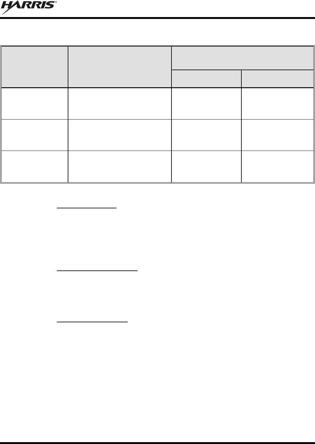
Table 1-1: Recommended Minimum Safe Lateral Distance from
Transmitting Antenna for Mobile Radio- to-Network Radio Link (VRMS7010 Transmit/Receive Antenna)
RECOMMENDED MINIMUM LATERAL HUMAN BODY
DISTANCE FROM TRANSMITTING ANTENNA
(Distance in Centimeters)
ANTENNA
PART NUMBER
(CATALOG NUMBER) ANTENNA DESCRIPTION
CONTROLLED
ENVIRONMENT UNCONTROLLED
ENVIRONMENT
AN-025167-001
(MAMW-AN3J) 700/800 MHz Standard
Rooftop-Mount; 3 dBd Gain 28 69
AN-025167-002
(MAMW-AN3K) 700/800 MHz Elevated-Feed
Rooftop-Mount; 3 dBd Gain 28 69
AN-025167-004
(MAMW-AN3V) 700/800 MHz GPS Combo
Rooftop-Mount; 3 dBd Gain 28 69
AN-025167-005
(MAMW-NAN3W)
700/800 MHz GPS Combo
Elevated-Feed Rooftop-Mount;
3 dBd Gain 28 69
AN-025167-006
(MAMW-NAN3X) 700/800 MHz Magnetic-Mount;
3 dBd Gain 29 72
AN-025167-010
(MAMW-NAN5B) 700/800 MHz Low-Profile
Rooftop-Mount; 2 dBd Gain 28 69
AN-025167-011
(MAMW-NAN5C)
700/800 MHz GPS Combo
Low-Profile Rooftop-Mount;
2 dBd Gain 28 69
AN-025167-014
(MAMW-NAN5U) 700/800 MHz Standard
Rooftop-Mount; 5 dBd Gain 39 87
AN-025167-015
(MAMW-NAN5V) 700/800 MHz GPS Combo
Rooftop-Mount; 5 dBd Gain 39 87
AN-125001-002
(mount) with
AN-225001-001
(element)
700/800 MHz Standard
Rooftop-Mount; 3 dBd Gain 36 76
AN-125001-002
(mount) with
AN-225001-005
(element)
700/800 MHz Standard
Rooftop-Mount; 5 dBd Gain 36 79
MM-018337-001
9
Table 1-2: Recommended Minimum Safe Lateral Distance from
Transmitting Antenna for Vehicular Repeater-to-P25 Radio Link (VRBS7010 Transmit/Receive Antenna)
RECOMMENDED MINIMUM LATERAL HUMAN
BODY DISTANCE FROM TRANSMITTING ANTENNA
(Distance in Centimeters)
ANTENNA
PART NUMBER ANTENNA DESCRIPTION
CONTROLLED
ENVIRONMENT UNCONTROLLED
ENVIRONMENT
AN-125001-002
(mount) with
AN-225001-004
(element)
Standard Rooftop-Mount with Low-
Loss Cable and 700/800 MHz Low-
Profile 2 dBd Gain Element 20 20
AN-125001-004
(mount) with
AN-225001-004
(element)
Thick Rooftop-Mount with Low-Loss
Cable and 700/800 MHz Low-Profile
2 dBd Gain Element 20 20
AN-125001-008
(mount) with
AN-225001-004
(element)
Magnetic-Mount with Low-Loss
Cable and 700/800 MHz Low-Profile
2 dBd Gain Element 20 20
1.3.1 Mobile Antennas
The antenna(s) for the radio must be installed in accordance with Section 7 in this manual. Refer to Figure
7-1 on page 36 for applicable antenna part numbers. Installation guidelines presented in Section 7 are
limited to metal-body motor vehicles or vehicles with appropriate ground planes.
Use only the Harris-approved/supplied antenna(s) or an approved replacement antenna. Unauthorized
antennas, modifications, or attachments can cause the FCC RF exposure limits to be exceeded.
1.3.2 Approved Accessories
The radio has been tested and meets FCC RF guidelines when used with accessories supplied or
designated for use with it. Use of other accessories may not ensure compliance with the FCC’s RF
exposure guidelines, and may violate FCC regulations. For a list of approved accessories refer to Section
4 in this manual (begins on page 20) and/or the Products and Services Catalog.
1.3.3 Contact Information
For additional information on RF exposure and other information, contact Harris using one of the contact
links listed in Section 3.7 on page 19.
1.4 OCCUPATIONAL SAFETY GUIDELINES AND SAFETY TRAINING
INFORMATION
To ensure bodily exposure to RF electromagnetic energy is within the FCC allowable limits for
occupational use. Always adhere to the following basic guidelines:
The push-to-talk button should only be depressed when intending to send a voice message.
The radio should only be used for necessary work-related communications.
The radio should only be used by authorized and trained personnel. It should never be operated by
children.
MM-018337-001
10
Do not attempt any unauthorized modification to the radio. Changes or modifications to the radio may
cause harmful interference and/or cause it to exceed FCC RF exposure limits. Only qualified
personnel should service the radio.
Always use only Harris-authorized accessories (antennas, control heads, speakers/mics, etc.). Use of
unauthorized accessories can cause the FCC RF exposure compliance requirements to be exceeded.
The information listed above provides the user with information needed to make him or her aware of a RF
exposure, and what to do to assure that this radio operates within the FCC exposure limits of this radio.
1.5 COMMON HAZARDS
The operator of any mobile radio should be aware of certain hazards common to
the operation of vehicular radio transmissions. Possible hazards include but are
not limited to:
Explosive Atmospheres — Just as it is dangerous to fuel a vehicle with its engine running, be sure to
turn the radio OFF while fuelling the vehicle. If the radio is mounted in the trunk of the vehicle, DO
NOT carry containers of fuel in the trunk.
Areas with potentially explosive atmosphere are often, but not always, clearly marked. Turn the radio
OFF when in any area with a potentially explosive atmosphere. It is rare, but not impossible that the
radio or its accessories could generate sparks.
Interference To Vehicular Electronic Systems — Electronic fuel injection systems, electronic anti-
skid braking systems, electronic cruise control systems, etc., are typical of the types of electronic
devices that can malfunction due to the lack of protection from radio frequency (RF) energy present
when transmitting. If the vehicle contains such equipment, consult the dealer for the make of vehicle
and enlist his aid in determining if such electronic circuits perform normally when the radio is
transmitting.
Electric Blasting Caps — To prevent accidental detonation of electric blasting caps, DO NOT use
two-way radios within 1000 feet (305 meters) of blasting operations. Always obey the “Turn Off
Two-Way Radios” (or equivalent) signs posted where electric blasting caps are being used. (OSHA
Standard: 1926.900).
Radio Frequency Energy — To prevent burns or related physical injury from radio frequency
energy, do not operate the transmitter when anyone outside of the vehicle is within the minimum safe
distance from the antenna as specified in Table 1-1 and Table 1-2. Refer to Section 1.2 for additional
information.
Vehicles Powered By Liquefied Petroleum (LP) Gas — Radio installation in vehicles powered by
liquefied petroleum gas, where the LP gas container is located in the trunk or other sealed-off space
within the interior of the vehicle, must conform to the National Fire Protection Association standard
NFPA 58. This requires:
The space containing the radio equipment must be isolated and sealed from the space containing
the LP gas container and its fittings.
Outside filling connections must be used for the LP gas container.
The LP gas container space shall be vented to the outside of the vehicle.
Vehicles Equipped with Airbags — For driver and passenger safety, avoid mounting the radio’s
control head (or any other component) above or near airbag deployment areas. In addition to driver-
side and passenger-side front-impact airbags, some vehicles may also be equipped with side-impact

MM-018337-001
11
airbags. For occupant safety, verify the location of all airbags within the vehicle before installing the
radio equipment.
1.6 SAFE DRIVING RECOMMENDATIONS
The American Automobile Association (AAA) advocates the following key safe driving recommenda-
tions:
Read the literature on the safe operation of the radio.
Keep both hands on the steering wheel and the microphone in its hanger whenever the vehicle is in
motion.
Place calls only when the vehicle is stopped.
When talking from a moving vehicle is unavoidable, drive in the slower lane. Keep conversations
brief.
If a conversation requires taking notes or complex thought, stop the vehicle in a safe place and
continue the call.
Whenever using a mobile radio, exercise caution.
1.7 OPERATING RULES REGULATIONS
Two-way radio systems must be operated in accordance with the rules and regulations of the local,
regional, or national government.
In the United States, the VRS7010 must be operated in accordance with the rules and regulations of the
Federal Communications Commission (FCC). Operators of two-way radio equipment, must be thoroughly
familiar with the rules that apply to the particular type of radio operation. Following these rules helps
eliminate confusion, assures the most efficient use of the existing radio channels, and results in a
smoothly functioning radio network.
When using a two-way radio, remember these rules:
It is a violation of FCC rules to interrupt any distress or emergency message. The radio operates in
much the same way as a telephone “party line.” Therefore, always listen to make sure the channel is
clear before transmitting. Emergency calls have priority over all other messages. If someone is
sending an emergency message – such as reporting a fire or asking for help in an accident, do not
transmit unless assistance can be offered.
The use of profane or obscene language is prohibited by Federal law.
It is against the law to send false call letters or false distress or emergency messages. The FCC
requires keeping conversations brief and confined to business. Use coded messages whenever
possible to save on-the-air time.
Using the radio to send personal messages (except in an emergency) is a violation of FCC rules. Send
only essential messages.
It is against Federal law to repeat or otherwise make known anything overheard on the radio.
Conversations between others sharing the channel must be regarded as confidential.
The FCC requires self-identification at certain specific times by means of call letters. Refer to the
rules that apply to the particular type of operation for the proper procedure.
No changes or adjustments shall be made to the equipment except by an authorized or certified
electronics technician.
MM-018337-001
12
CAUTION
Under U.S. law, operation of an unlicensed radio transmitter within the jurisdiction of
the United States may be punishable by a fine of up to $10,000, imprisonment for up to
two (2) years, or both.
1.8 OPERATING TIPS
The following conditions tend to reduce the effective range of two-way radios and should be avoided
whenever possible:
Operating the radio in areas of low terrain, or while under power lines or bridges.
Obstructions such as mountains and buildings.
In areas where transmission or reception is poor, communication improvement may
sometimes be obtained by moving a few yards in another direction, or moving to a
higher elevation.

MM-018337-001
13
2 SPECIFICATIONS1
2.1 GENERAL
Dimensions (Height x Width x Depth):
VRMS7010: 5.2 x 8.8 x 9.3 inches (13.2 x 22.4 x 23.6 centimeters)
(Includes bracket but not space required for cables)
VRBS7010: 7.3 x 8.8 x 9.3 inches (18.5 x 22.4 x 23.6 centimeters)
(Includes bracket but not space required for cables)
Control Head: 2.4 x 6.9 x 3.9 inches (6 x 17.5 x 10 centimeters)
(Does not include bracket and mounting screws)
Weights
VRMS7010: 13.6 pounds (6.17 kilograms), less mounting bracket
VRBS7010: 13.6 pounds (6.17 kilograms), less mounting bracket
Control Head: 1.25 pounds (0.57 kilograms), less mounting bracket
VRMS7010 and VRBS7010 Mounting Brackets: 1.25 pounds (0.57 kilograms) each
Cable, Interface: 1.25 pounds (0.57 kilograms)
Operating Ambient Temperature Range: -22 to +140° Fahrenheit (-30 to +60° Celsius)
Storage Temperature Range: -40 to +185° Fahrenheit (-40 to +85° Celsius)
Altitude
Operating: 15,000 feet (4572 meters) maximum
Storage/Shipment: 50,000 feet (15,240 meters) maximum
DC Supply Voltage Operating Range: +13.6 Vdc ±10% (Normal range per TIA-603)
DC Supply Current, VRS7010
VRMS7010
Receive: 1.1 amps maximum
Transmit at 15 Watts Tx Power: 8 amps maximum, 6 amps typical
Transmit at 35 Watts Tx Power: 15 amps maximum, 12 amps typical
Quiescent/Off Current: 2 milliamps maximum
VRBS7010
P25 Vehicular Repeater Mode Disabled: 5 milliamps maximum, 2 milliamps typical
P25 Vehicular Repeater Mode Enabled: 6 amps maximum, 5 amps typical
Quiescent/Off Current: 5 milliamps maximum, 2 milliamps typical
DC Supply Current, CH-721 Control Head
With ½-Watt Speaker Output Power: 0.9 amps maximum
With 10-Watts Speaker Output Power: 2.0 amps maximum
With 15-Watts Speaker Output Power: 2.4 amps maximum
Standby Current (Muted): 0.6 amps maximum
Quiescent/Off Current: 100 microamps maximum
1 These specifications are primarily intended for the use of the installation technician. See the appropriate Specifications
Sheet for the complete specifications.

MM-018337-001
14
For detailed transceiver-related specifications on the VRMS7010, refer to the M7300
mobile radio’s installation or maintenance manuals, publications MM-014763-001 or
MM-014718-001 respectively.
For detailed transceiver-related specifications on the VRBS7010, refer to the VRS7010’s
maintenance manual, publication MM-018338-001.
2.2 REGULATORY
FCC Identification Numbers:
VRMS7010: OWDTR-0051-E
VRBS7010: (TBD)
Applicable FCC Rules: Part 90 and Part 15
Industry Canada Certifications:
VRMS7010: 3636B-0051
VRBS7010: (TBD)
Applicable Industry Canada Rules: RSS-119
MM-018337-001
15
3 INTRODUCTION
This manual contains product safety and installation-related procedures for the VRS7010 vehicular
repeater with mobile radio, together with the CH-721 control head. Installation procedures cover the
mounting and cabling of the equipment, as well as the basic testing of the mobile radio and control head.
An interconnection wiring diagram is included at the rear of this manual. Important product safety-related
information is presented in Section 1.
3.1 GENERAL INFORMATION
The VRS7010 is a combination Project 25 (P25) vehicular repeater for P25 trunked radio networks and a
mobile radio for trunked and conventional radio networks. The VRS7010 consists of two (2) mobile
systems.
3.1.1 Vehicular Repeater Base System (VRBS7010)
The system that provides the RF link for nearby P25 radios when the VRS7010 is operating as a P25
vehicular repeater is called the Vehicular Repeater Base System (VRBS7010). As illustrated in Figure 5-2
on page 29, the VRBS7010 is formed by a Vehicular Repeater Base (VRB), a Traffic Controller module,
and a 700 MHz duplexer module. The VRB is the transceiver for the RF link to nearby P25 radios. The
Traffic Controller section interfaces the VRB to the VRM which transmits radio audio and control
information to the site. The filter allows the VRB to operate with a single vehicle-mounted transmit-
receive antenna. See Figure 3-1.
3.1.2 Vehicular Repeater Mobile System (VRMS7010)
The system that provides network access is called the Vehicular Repeater Mobile System (VRMS7010).
The VRMS7010 consists of an remote-mount M7300 mobile radio and an 800 MHz bandpass filter. The
M7300 is the Vehicular Repeater Mobile (VRM) radio within the VRMS7010. The 800 MHz bandpass
filter is in series with the M7300 radio’s antenna port and the vehicle-mounted antenna. This combination
provides connectivity to an 800 MHz trunked or conventional radio network. The M7300 mobile radio is
a dual-band 700 and 800 MHz mobile radio; however, in this application, only the 800 MHz RF band is
supported. The VRMS7010 is shown in Figure 5-1 on page 28.
Figure 3-1: Simplified Radio-to-Network Block Diagram with VRS7010

MM-018337-001
16
When operating as a P25 vehicular repeater, the VRS7010 provides an end-to-end P25 communication
link between nearby P25 trunked radios and a P25 trunked radio network. The VRS7010’s network
extension enables nearby P25 radios to maintain radio communications on a P25 radio network. In this
mode, normal mobile radio communications cannot be accomplished from the radio’s control head. The
radio’s microphone is disabled when it is operating in the P25 vehicular repeater mode.
When it is operating as a mobile radio (i.e., P25 vehicular repeater mode disabled), the VRS7010 supports
communications on P25 trunked and P25 conventional radio systems. As such, the VRS7010’s vehicular
repeater functionality is not available. When the VRS7010 is operating as a mobile radio, the VRBS7010
is completely powered off and disabled and the VRMS7010 provides half-duplex voice and data
communications. Voice communications are accomplished via the “push-to-talk” (PTT) type microphone
and the speaker connected to the control head.
A VRS7010 installation typically requires two (2) vehicle-mounted mobile antennas. One combination
(“combo”) type mobile antenna is typically used for the VRMS7010 and its built-in GPS receiver, and
another vehicle-mounted mobile antenna is required for the VRBS7010. If the VRMS7010 is not
connected to a combo-type antenna (i.e., if the GPS receiver antenna is not integrated into the VRMS7010
transmit/receive antenna) and the VRMS7010 is equipped with a GPS receiver option, a third vehicle-
mounted antenna is required for the GPS receiver within the VRMS7010. Antenna installation procedures
are included in Section 7 of this manual. A wiring diagram is shown at the end of this manual.
A VRS7010 installation also includes a CH-721 System model control head with a microphone and a
speaker. This equipment provides the interface for the VRS7010’s operator/user. Mounting and
installation accessories complete the mobile radio equipment package. Additional control head
information is included in Section 3.3, and control head installation procedures are included in Section 10
of this manual.
The VRS7010 and the CH-721 exceed many tough environmental specifications included within military
standard MIL-STD-810F, automotive industry standard SAE-J1455, the radio industry standard
TIA/EIA-603, and the radio standard established by the U.S. Forest Service.
3.2 OPERATING MODES
The VRS7010 vehicular repeater with mobile radio has two (2) primary operating modes as described in
the following subsections:
3.2.1 Standard Mobile Radio Mode
When the VRS7010 is operating in the standard mobile radio mode, it functions like a normal mobile
radio. The radio operator uses the interfaces of the connected CH-721 control head (i.e., display, control
buttons/keys, mic and speaker) to control the radio and to communicate with other radio users and
console dispatchers on a trunked or conventional radio network. Nearby P25 radios cannot be linked
through the VRS7010 to the radio network when the VRS7010 is operating in this mode. The VRS7010’s
vehicular repeater functionality is disabled when it is in this operating mode. The VRBS7010 is
completely powered off and disabled.
3.2.2 Extended Coverage (XCOV) Vehicular Repeater Mode
When the VRS7010 is operating in the extended coverage vehicular repeater mode, it provides the
network extension interface that enables nearby P25 radios to access the P25 radio network through the
VRS7010. This mode’s name is typically abbreviated “XCOV vehicular repeater mode,” “XCOV mode”
or simply “VR mode.” Radio coverage for nearby P25 radios is extended because VRS7010’s high-
performance mobile antenna system and higher transmitter output power used to access the P25 network.
See Figure 3-1. When a nearby P25 radio is communicating through the VRS7010, it is considered

MM-018337-001
17
“connected” to and a “client” on the VRS7010. The VRS7010 cannot function as a standard mobile radio
when it is operating in this mode.
Typically, the VRS7010 operator places the radio into this mode via a menu selection or preset button
press at the installation’s CH-721 control head. Likewise, the operator can disable this mode via a
CH-721 control head menu selection or preset button press. Alternately, the radio installation may be
wired so this mode can be enabled and disabled by an external switch.
When the VRS7010 is operating in this mode, its VRBS7010 functions like a Voice and Data Over
Control (VDOC) site for the nearby P25 radios. Essentially, the connected P25 radios and the VRBS7010
are linked together via P25 VDOC protocols on the VRBS7010 RF channel.
When using the XCOV vehicular repeater mode, P25 radios operating through the VRS7010 maintain the
following P25 functions across the two RF links:
P25 Group Call — Both digital clear voice and digital encrypted voice group calls are supported.
P25 Individual Call — Unit-to-unit calls both between two connected P25 radios and between a
nearby P25 radio and a radio/console on the P25 radio network are supported.
P25 User ID — Caller identification information is sent between a connected P25 radio and the P25
radio network.
P25 Emergency — The link through the VRS7010 provides P25 emergency communications
between the P25 radios connected to the VRS7010 and the P25 radio network.
P25 System All Call (from Network Only) — A system-wide all-call transmission from the P25
radio network is forwarded to P25 radios connected to the VRS7010.
Call Grant and Call Queued Tones — A P25 radio connected to the VRS7010 generates call grant
and call queued tones in a similar manner as if was operating directly on the P25 radio network.
A single VRS7010 allows attachment of up to sixty-four (64) nearby P25 radios. Each radio may
communicate on the same talk group, or on multiple different talk groups (up to sixty-four maximum talk
groups for one talk group per radio). Each connected P25 radio can communicate on the P25 network via
the VRS7010.
When operating in the XCOV vehicular repeater mode, calls transmitted from connected P25 radios are
not routed to the VRS7010’s speaker.
The VRS7010 supports end-to-end Advanced Encryption Standard (AES) encrypted calls. In other words,
if a P25 radio connected to the VRS7010 is transmitting an encrypted call, the VRS7010 simply repeats
the call to the network base station; it does not un-encrypt and then re-encrypt the call.
3.3 EQUIPMENT MOUNTING AND CONTROL HEAD
The VRS7010 is designed for remote mounting in a motor vehicle’s trunk, or some other preferably
unoccupied section in a vehicle, such as a fire truck’s equipment shelf. A 3-wire Controller Area Network
(CAN) cable provides radio-to-control head(s) interconnection. One end of the CAN cable connects to a
CAN port on the rear of the VRS7010’s VRMS7010 mobile radio and the other end connects to a CAN
port on the rear of the CH-721 control head. Between the radio and the control head, the CAN link carries
digitized microphone and speaker audio, and controlling data such as button presses and radio messages.
For proper operation, the CAN link must be terminated appropriately on each end.
The CH-721 System model control head provides the user/operator interface for the VRS7010. See Figure
10-2 on page 49. This control head has a large 3-line graphical vacuum-fluorescent display, front panel
controls and buttons for user control of the mobile radio, an internal high-power audio amplifier to drive
an externally-connected speaker, and a front panel microphone connector. It features a 12-key numeric
MM-018337-001
18
keypad that provides Dual-Tone Multi-Frequency (DTMF) keypad functionality and easier operator
system/group selection, three (3) preset buttons, and an emergency/home button.
As shown in Figure 10-2 on page 49, the CH-721 System model control head has several connectors
located on its rear panel. These connectors include a DC power connector, two (2) CAN port connectors
used for CAN link interconnections, an external speaker connector, a 9-pin serial port connector for
connecting optional equipment such as a mobile data terminal, and a 25-pin multi-function connector.
3.4 OPERATING POWER
The VRS7010 must be powered by an external +13.6-volt (nominal) DC power source. In mobile
applications, the motor vehicle’s electrical system is utilized as the source of DC power. The VRS7010’s
VRMS7010 and VRBS7010 are separately fused. For detailed specifications, see Section 2 of this manual
which begins on page 13.
The control head(s) connected to the radio is also powered by the same DC power source, but fused
separately from the two (2) radios. When the control head is powered-up by the operator, it “wakes up”
the VRM radio by transmitting data to the radio over the CAN link.
CAUTION
Harris recommends the buyer use only a Harris-authorized representative to
install and service this product. The warranties provided to the buyer under the terms
of sale shall be null and void if this product is installed or serviced improperly, and
Harris shall have no further obligation to the buyer for any damage caused to the
product or to any person or personal property.

MM-018337-001
19
3.5 RELATED PUBLICATIONS
The following publications contain additional information about the VRS7010:
Operator’s Manual: MM-018336-001
Maintenance Manual: MM-018338-001
All of the above listed publications are available at www.pspc.harris.com via a Wireless
Systems’ Wireless Information Center login and Tech Link. In addition, the Quick
Guides are included with the radio when it ships from the factory.
3.6 REPLACEMENT PARTS
Replacement parts can be ordered through the Customer Resource Center. To order replacement parts
through the Customer Resource Center, call, fax or e-mail our ordering system:
United States and Canada:
Phone Number: 1-800-368-3277 (toll free)
Fax Number: 1-800-833-7592 (toll free)
E-mail: PSPC_CustomerFocus@harris.com
International:
Phone Number: 1-434-455-6403
Fax Number: 1-434-455-6676
E-mail: PSPC_InternationalCustomerFocus@harris.com
3.7 TECHNICAL ASSISTANCE
Should the mobile radio or control head require repair, or if there are questions or concerns about the
installation of this equipment, contact the Technical Assistance Center (TAC) using the following
telephone numbers or e-mail address:
United States and Canada: 1-800-528-7711 (toll free)
International: 1-434-385-2400
Fax: 1-434-455-6712
E-mail: PSPC_tac@harris.com

MM-018337-001
20
4 UNPACKING AND CHECKING THE EQUIPMENT
4.1 MATERIALS
A typical set of VRS7010 installation materials includes:
VRS7010 Vehicular Repeater Mobile System (VRMS7010), consists of:
M7300 Remote-Mount Mobile Radio [See Table 4-1 below for part and catalog number]
VRS7010 VRM 800 MHz Bandpass Filter [See Table 4-1 below for part and catalog number]
VRS7010 Vehicular Repeater Base System (VRBS7010)
[See Table 4-1 below for part and catalog number]
CH-721 System Control Head [part number CU23218-0004; catalog number MAMW-CP9F]
Standard Microphone [part number MC-101616-041; part of catalog number MAMW-MC7Z]
Installation Kit MAMW-NZN8X for VRS7010 and CH-721 as listed in Table 4-2
Two (2) or Three (3) Antennas as listed in Table 4-3
Table 4-1: VRS7010 Catalog and Part Numbers
CATALOG NUMBER PART NUMBER DESCRIPTION
MAMW-SDMXX RU-144750-061
Remote-Mount Dual-Band 700/800 MHz
M7300 Mobile Radio (VRM Radio of
VRMS7010)
MAMW-NFL1A FL-017938-010 800 MHz Bandpass Filter
(Bandpass Filter of VRMS7010)
MAMW-VDLXX RU-017933-010 VRBS7010
The Installation Kit can be used to install the VRS7010, or individual components may be purchased
separately as needed. Table 4-2 lists the parts included in the kit. Table 4-3 lists part numbers for radio
options and accessories. Table 4-4 includes optional parts available for the CH-721 control head.
MM-018337-001
21
Table 4-2: Installation Kit MAMW-NZN8X for VRS7010 and CH-721
ITEM QTY. PART NUMBER DESCRIPTION ILLUSTRATION
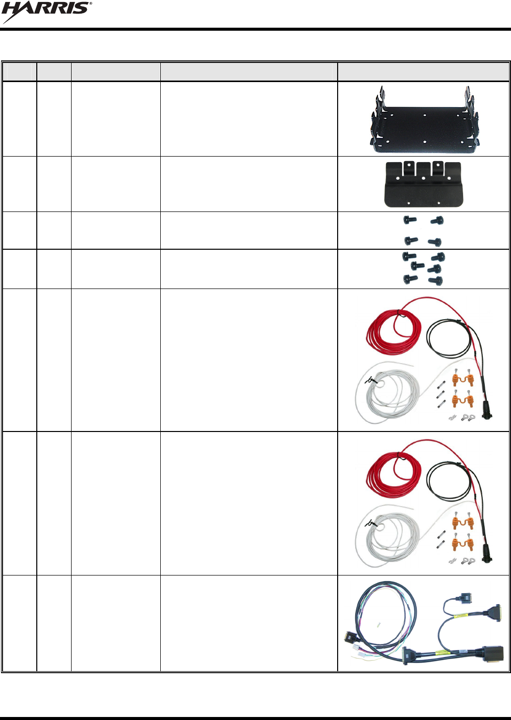
1 2
1000003678 Bracket, Base.
2 2
FM-018205 Extension Bracket.
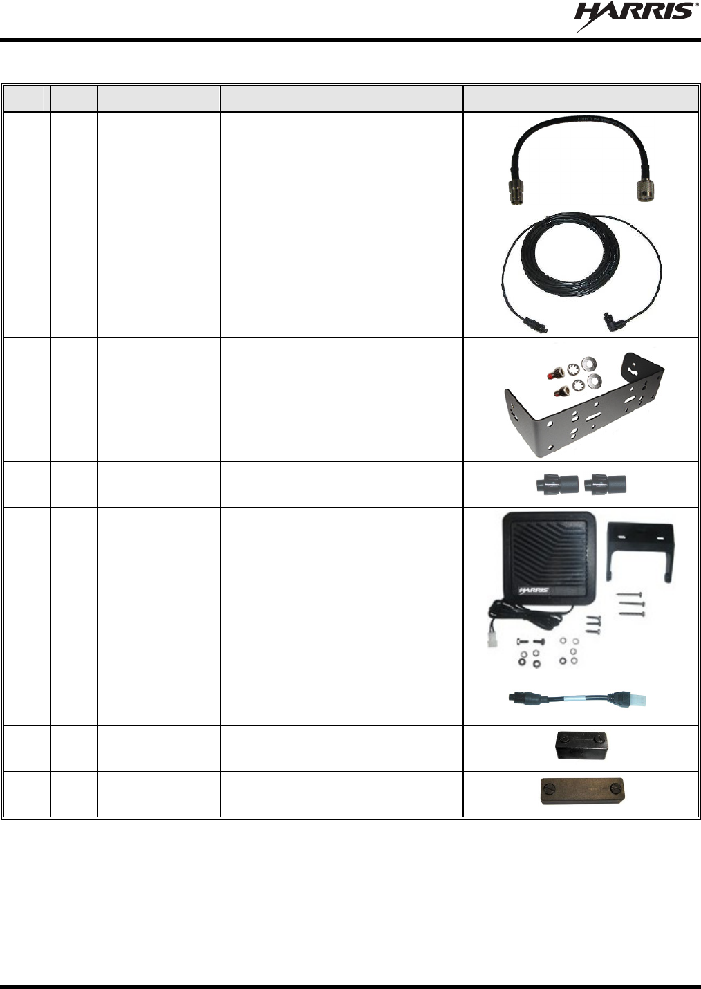
3 4
AD00006 Screws: #8-32 Pan-Head (Package
of 4 screws).
4 1
SC-018424 Screws: M5 x 10 mm Philips-Head
SEMS Screws (Package of 6
screws).
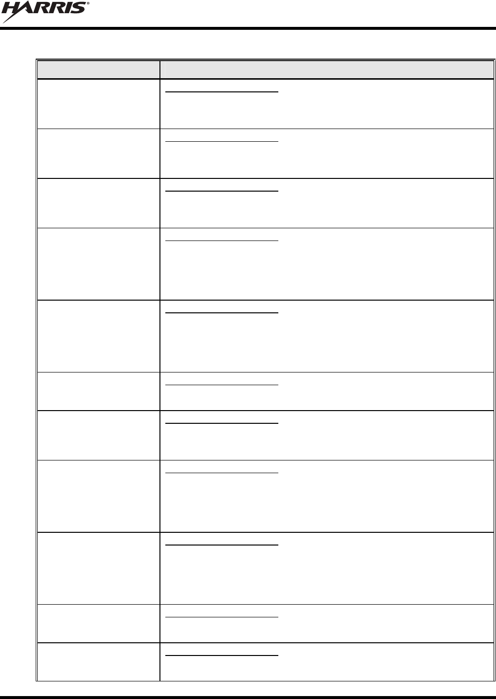
5 2
CA-012365-001 Cable, M7200/M7300/M5300 DC
Power. Includes (1) 20-Foot DC
Power Cable with straight connector,
(2) waterproof inline HFB-type fuse
holders, (1) 3-amp AGC fuse, (1)
15-amp AGC fuse, and (1) 20-amp
AGC fuse.
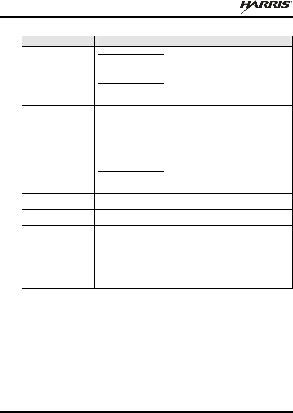
6 1
CA-012616-001 Cable, CH-721 DC Power. Includes
(1) DC Power Cable with straight
connector, (2) waterproof inline HFB-
type fuse holders, (1) 3-amp AGC
fuse, and (1) 5-amp AGC fuse. This
DC Power Cable has a 10-foot
12-AWG red wire (main power input),
a 20-foot white wire (switched power
input), and a 5-foot black wire
(ground).
7 1
CA-012349-003 Cable, VRS7010 Interface.
MM-018337-001
22
Table 4-2: Installation Kit MAMW-NZN8X for VRS7010 and CH-721
ITEM QTY. PART NUMBER DESCRIPTION ILLUSTRATION
8 1
CA-018378 Cable, RF; TNC Female to TNC
Male.
9 1
CA-009562-030 Cable, CAN; 30 feet, Right-Angle-to-
Straight Connectors.
10 1
KT-008608 Kit, CH-721 Mounting Bracket.
Includes (1) U-Shaped Mounting
Bracket, (2) ¼-Inch #8-32 stainless-
steel screws, (2) stainless-steel flat
washers and (2) stainless-steel
lockwashers.
11 2
CD-014027-
001
Terminator, CAN; 3-Pin, Straight
Body.
12 1
LS102824V10 Speaker, External Mobile; 20-Watt
(with 4.6-foot cable).
13 1
MAMROS0034-
NN006
Cable, Speaker; 6-Inch, Straight
Connector.
14 1
FM-104859-
001
Cap, Waterproof (For CH-721’s DB-9
serial port connector).
15 1
FM-104859-
002
Cap, Waterproof (For CH-721’s
DB-25 accessory connector).
MM-018337-001
23
Table 4-3: Options and Accessories for VRS7010
PART NUMBER DESCRIPTION
AN-025167-001
(Catalog No. MAMV-AN3J) For VRMS7010 Use Only: Antenna, 700/800 MHz, Standard Rooftop-
Mount, 3 dB Gain, NMO Mounting Base, 15-foot (4.6-meter) RG-58 A/U
(or equivalent) Low-Loss RF Cable, Male TNC and Mini-UHF RF
Connectors; Factory-Tuned.
AN-025167-014
(Catalog No. MAMV-NAN5U) For VRMS7010 Use Only: Antenna, 700/800 MHz, Standard Rooftop-
Mount, 5 dBd Gain, NMO Mounting Base, 15-foot (4.6-meter) RG-58 A/U
(or equivalent) Low-Loss RF Cable, Male TNC and Mini-UHF RF
Connectors, Factory-Tuned.
AN-025167-002
(Catalog No. MAMV-AN3K) For VRMS7010 Use Only: Antenna, 700/800 MHz, Elevated-Feed,
Rooftop-Mount, 3 dB Gain, NMO Mounting Base, 15-foot (4.6-meter) RG-
58 A/U (or equivalent) Low-Loss RF Cable, Male TNC and Mini-UHF RF
Connectors; Factory-Tuned.
AN-025167-004
(Catalog No. MAMV-AN3V) For VRMS7010 Use Only: Antenna, 700/800 MHz GPS Combo, Rooftop-
Mount, 3 dB Gain, NMO Mounting Base, 15-foot (4.6-meter) RG-58 A/U
(or equivalent) Low-Loss RF Cable, Male TNC and Mini-UHF RF
Connectors, 16.5-foot (5-meter) RG174/U (or equivalent) GPS RF Cable
with Male SMA RF Connector (attached); 2.7 to 3.3 Vdc or 4.8 to 5.2 Vdc
Bias; Factory-Tuned.
AN-025167-005 For VRMS7010 Use Only: Antenna, 700/800 MHz GPS Combo, Elevated-
Feed Rooftop-Mount, 3 dBd Gain, NMO Mounting Base, 15-foot (4.6-meter)
RG-58 A/U (or equivalent) Low-Loss RF Cable, Male TNC and Mini-UHF RF
Connectors, 16.5-foot (5-meter) RG174/U (or equivalent) GPS RF Cable with
Male SMA RF Connector (attached); 2.7 to 3.3 Vdc or 4.8 to 5.2 Vdc Bias;
Factory-Tuned.
AN-025167-006 For VRMS7010 Use Only: Antenna, 700/800 MHz, Magnetic-Mount,
3 dBd Gain, 15-foot (4.6-meter) RG-58 A/U (or equivalent) Low-Loss RF
Cable, Male TNC and Mini-UHF RF Connectors; Factory-Tuned.
AN-025167-010 For VRMS7010 Use Only: Antenna, 700/800 MHz, Low-Profile, Rooftop-
Mount, 2 dBd Gain, NMO Mounting Base, 15-foot (4.6-meter) RG-58 A/U
(or equivalent) Low-Loss RF Cable, Male TNC and Mini-UHF RF
Connectors, Factory-Tuned.
AN-025167-011 For VRMS7010 Use Only: Antenna, 700/800 MHz GPS Combo, Low-
Profile, Rooftop-Mount, 2 dBd Gain, NMO Mounting Base, 15-foot (4.6-
meter) RG-58 A/U (or equivalent) Low-Loss RF Cable, Male TNC and Mini-
UHF RF Connectors, 16.5-foot (5-meter) RG174/U (or equivalent) GPS RF
Cable with Male SMA RF Connector (attached); 2.7 to 3.3 Vdc or 4.8 to 5.2
Vdc Bias; Factory-Tuned.
AN-025167-015
(Catalog No. MAMV-NAN5V) For VRMS7010 Use Only: Antenna, 700/800 MHz GPS Combo, Rooftop-
Mount, 5 dBd Gain, NMO Mounting Base, 15-foot (4.6-meter) RG-58 A/U
(or equivalent) Low-Loss RF Cable, Male TNC and Mini-UHF RF
Connectors, 16.5-foot (5-meter) RG174/U (or equivalent) GPS RF Cable
with Male SMA RF Connector (attached); 2.7 to 3.3 Vdc or 4.8 to 5.2 Vdc
Bias; Factory-Tuned.
AN-025187-001
(Catalog No. MAMV-NAN5F) For VRMS7010 Use Only: Antenna, GPS Receive Only, Roof-Mount,
17-foot (5.2-meter) RG174/U (or equivalent) RF Cable with Male SMA RF
Connector (attached); 2.7 to 3.3 Vdc or 4.8 to 5.2 Vdc Bias.
AN-025187-003
(Catalog No. MAMV-AN3L) For VRMS7010 Use Only: Antenna, GPS Receive Only, Magnetic-Mount,
17-foot (5.2-meter) RG174/U (or equivalent) RF Cable with Male SMA RF
Connector (attached); 2.7 to 3.3 Vdc or 4.8 to 5.2 Vdc Bias.
MM-018337-001
24
Table 4-3: Options and Accessories for VRS7010
PART NUMBER DESCRIPTION
AN-125001-002 (mount)
with AN-225001-001
(element)
For VRMS7010 Use Only: Antenna, 700/800 MHz, Standard Rooftop-
Mount, 3 dBd Gain, NMO Mounting Base, 15-foot (4.6-meter) LMR-195 (or
equivalent) Low-Loss RF Cable, Male TNC and Mini-UHF RF Connectors;
Factory-Tuned.
AN-125001-002 (mount)
with AN-225001-005
(element)
For VRMS7010 Use Only: Antenna, 700/800 MHz, Standard Rooftop-
Mount, 5 dBd Gain, NMO Mounting Base, 15-foot (4.6-meter) LMR-195 (or
equivalent) Low-Loss RF Cable, Male TNC and Mini-UHF RF Connectors;
Factory-Tuned.
AN-125001-002 (mount)
with AN-225001-004
(element)
For VRBS7010 Use Only: Antenna, Standard Rooftop-Mount with NMO
Mounting Base, 15-foot (4.6-meter) LMR-195 (or equivalent) Low-Loss RF
Cable, Male TNC RF Connector and 700/800 MHz Low-Profile 2 dBd Gain
Element.
AN-125001-004 (mount)
with AN-225001-004
(element)
For VRBS7010 Use Only: Antenna, Thick Rooftop-Mount with NMO
Mounting Base, 15-foot (4.6-meter) LMR-195 (or equivalent) Low-Loss RF
Cable, Male TNC RF Connector and 700/800 MHz Low-Profile 2 dBd Gain
Element.
AN-125001-008 (mount)
with AN-225001-004
(element)
For VRBS7010 Use Only: Antenna, Magnetic-Mount with NMO Antenna-
to-Base Interface, 15-foot (4.6-meter) LMR-195 (or equivalent) Low-Loss
RF Cable, Male TNC RF Connector and 700/800 MHz Low-Profile 2 dBd
Gain Element.
CN-014756 Connector, RF; TNC Male Crimp-Type for RG58U, RG58A/U and RGU400
Coaxial Cable.
CA-013671-020 Cable, TIA/EIA/RS-232 Serial Programming, 20 feet. See Figure 13-1 on
page 60.
KT-012350-001
(Cat. No. MAMW-NMK5F) Kit, GPS Receiver for M5300/M7300.
KT-015037 Kit, Front-Mount to Remote-Mount Conversion for M5300/M7300 Radio.
Includes CH-721 Conversion Kit, CH-721 Mounting Bracket Kit, CH-721
DC Power Cable, CAN Cable, CAN Terminator, Speaker Cable, Etc.
KT-014494-002 Kit, Remote-Mount to Front-Mount Conversion for M5300/M7300 Radio
and CH-721 Control Head.
CD-014027-001 Terminator, CAN; 3-Pin, Straight Body.

MM-018337-001
25
Table 4-4: Accessories for CH-721 Control Heads
PART/MODEL NUMBER DESCRIPTION
CA-009562-006 Cable, CAN; 6 feet, Right-Angle-to-Straight Connectors.
CA-009562-030 Cable, CAN; 30 feet, Right-Angle-to-Straight Connectors.
CA-009562-090 Cable, CAN; 90 feet, Right-Angle-to-Straight Connectors.
CA-009562-250 Cable, CAN; 250 feet, Right-Angle-to-Straight Connectors.
CA-011854-001 Cable, CH-721 Option. (Shown in Figure 13-2 on page 61.)
MACDOS0012 Kit, Control Head Pedestal Mounting. Includes Pedestal Mount and
Mounting Screws.
MACDOS0013-CN004 Kit, Speaker; 20-Watt, Straight Connector. (Includes 4-Ohm 20-Watt
Speaker LS102824V10 with 4.6-Foot Cable and 6-Inch Speaker Cable
MAMROS0034-NN006.)
FS24473 Kit, Vehicle Fuse and T-Tap. Includes (1) ATM Fuse Holder, (1) 2-Amp
ATM Fuse, (2) T-Tap Quick-Disconnect Terminals and (1) ¼-Inch
Crimp Tab Terminal. (Contents shown in Figure 10-6 on page 56.)
MC-101616-041 Microphone, Standard with Flush-Mount 90-Degree Connector
(Included with catalog number MAMV-MC7Z)
MC-103334-040 Microphone, DTMF with Flush-Mount 45-Degree Connector
(Included with catalog number MAMV-NMC9C)
MC-103334-041
(See footnote 2) Microphone, DTMF with Flush-Mount 90-Degree Connector
MC-103334-050 Microphone, Noise-Canceling with Flush-Mount 45-Degree Connector
(Included with catalog number MAMV-NMC9D)
MC-103334-051
(See footnote 2) Microphone, Noise-Canceling with Flush-Mount 90-Degree Connector
344A4678P1 Microphone Hanger. (Included with catalog numbers MAMV-MC7Z,
MAMV-NMC9C and MAMV-NMC9D.)
MACDOS0010 Terminator, CAN; 3-Pin, Right-Angle Body.
CD-014027-001 Terminator, CAN; 3-Pin, Straight Body.
2 As of the publication of this manual, microphones MC-103334-041 and MC-103334-051 are not available. These two
mics have 90-degree connectors (also called “straight connectors”). See Section 3.6 for additional information.
MM-018337-001
26
4.2 MATERIAL INSPECTION
CAUTION
After removal from the carton, examine the mobile radios, control head and other
components for broken, damaged, loose or missing parts. If any are noted, contact the
Customer Resource Center (see page 19) immediately to discuss and arrange the return
of the equipment to Harris for replacement. Any unauthorized attempts to repair or
modify this equipment will void the warranty and could create a safety hazard.
Upon removing items from the carton and verifying that all equipment is accounted for, proceed with the
installation.
CAUTION
Mounting of the radios, control head, and/or antenna in ways other than those described
in this manual may adversely affect performance, violate FCC rules on RF exposure,
and even damage the unit, posing a potential safety hazard.
MM-018337-001
27
5 PLANNING THE INSTALLATION
5.1 GENERAL INFORMATION
Before beginning the radio installation, plan it carefully so it will meet the following requirements:
The installation is safe for the operator and passengers within the vehicle.
The equipment is installed away from the airbag deployment areas.
The installation allows for convenient access by the operator, as applicable (i.e., the control head).
The equipment is protected from water damage.
The installation is neat and allows easy service access.
The radio is mounted in a location assuring the vehicle occupant’s safety and out of the way of
passengers and auto mechanics.
The two (2) transmit/receive antennas can be mounted at least three (3) feet (0.92 meters) apart.
CAUTION
A professional radio installer should perform the installation!
5.2 TOOLS REQUIRED
The following list of equipment is recommended for the installation. Equivalents may be used unless
otherwise specified:
Non-Insulated Crimp Tool: Thomas & Betts
WT-111-M
Insulated Terminal Crimp Tool: Klein 1005
Fuse Holder Crimp Tool: Thomas & Betts –
WT-112M or California Terminal Products
No. 1250 or Channelock No. 909
3-Blade Coax Cable Stripper for RG-58
Cable similar to Tyco Electronics 1490490-
1 (includes blades)
Ratcheting Hex-Crimp Tool for 50-Ohm TNC
and BNC RF Connectors and RG-58 Cable
similar to Tyco Electronics 58433-2 (includes
Crimper 354940-1 and Die Set 58436-1) or
Emerson Network Power 24-9960P
Non-Metallic Fish Tape, 25-Foot: Klein-
Lite 50156
Two Pairs of Soft-Jaw Pliers: Tessco
450520 or equivalent
Flush-Cut and Large Wire Cutters
Phillips-Head Screwdrivers, #1 and #2
Flat-Blade Screwdrivers, #1 and #2
⅛-Inch Hex Key Wrench (Allen Wrench)
5/16-Inch Combination or Open-End Wrench
Socket and/or Nut Driver Sets
¾-Inch Hole Saw with Depth Protection:
Ripley HSK 19 or Antenex HS34
Clutch-Type (i.e., with torque limit)
Cordless Drill with Drill Bits and Driver
Bits
Deburring Tool (for ⅜-inch and smaller
holes)
Tie Wraps: 6-inches or larger
Various Fasteners (e.g., machine screws and
nuts, Tek screws, etc.)
A separate list of test equipment is included in Section 16.1 on page 66.
MM-018337-001
28
VRMS7010 FRONT-SIDE VEW
VRMS7010 REAR VIEW
(Shown Without Any Installation-Related Cables Connected)
Figure 5-1: VRS7010’s Vehicular Repeater Mobile System (VRMS7010)
V
RM Radio’s Option
Connector
(Female DB-44)
800 MHz Bandpass Filte
r
GPS Antenna Cable’s SMA Connecto
r
800 MHz Bandpass
Filter’s Antenna
Connector
(Female TNC)
CAN Port Connectors
(2 Places)
VRM Radio
(M7300)
800 MHz
Bandpass Filte
r
Base Bracket
Extension Bracket
(2 places)
RF Cable
(Female TNC
to Male TNC)
VRM Radio (M7300)
VRM Radio’s DC Power Cable
(with 3-Pin Connector)
VRM Radio’s Serial
Port Connector
(Female DB-44)
MM-018337-001
29
VRBS7010 FRONT-SIDE VEW
VRBS7010 REAR VIEW
(Shown Without Any Installation-Related Cables Connected)
Figure 5-2: VRS7010’s Vehicular Repeater Base System (VRBS7010)
Traffic Controller
Vehicular Repeater
Base (VRB) Radio
700 MHz Duplexe
r
DC Power Cable of
VRBS7010 (with 3-Pin
Connector)
Antenna Cable of
VRBS7010 (with female TNC
Interface Cable of
VRBS7010 (with DB-25
Mounting Bracket
Not Shown.
Ethernet Cable
(Not Shown)
Mounting Bracket
Not Shown.
MM-018337-001
30
5.3 LOCATING COMPONENTS
Plan the mounting locations of all components (VRS7010, CH-721, antennas, and cables) and determine
the routes for all wiring and cables. Particularly consider the connection of the control head for planning
purposes.
Determine the customer’s preferences, if any, for location of components. Comply with these
preferences as long as they are consistent with safety recommendations and guidelines presented in
this manual, and other generally accepted professional radio installation practices.
Nominal dimensions for the VRS7010 and the CH-721 are listed in Section 2.1 of this manual (page
13). These dimensions do not include any clearance space required for cabling, air circulation, access
to mounting hardware, etc. Always plan for and include adequate clearance around the radios.
The VRMS7010 and the VRBS7010 must be located and mounted within approximately twelve (12)
inches of each other.
Verify sufficient clearance behind the radios is provided so cables will not be stressed, crushed,
twisted, or bent at severe angles. Also, the front and sides must have clearance for air circulation,
access to mounting hardware, etc.
Connections at the VRS7010 are made through both “pigtail” type cables exiting the rear of its two
radios, and panel-mount type connectors. This design minimizes the stresses associated with mating
connections and it allows for easy connector mating. However, stresses can still be induced if
adequate service looping is not employed. Connections to the control head is made with connectors
mounted on the rear panel of each head, instead of “pigtail” type cables.
The VRS7010’s two (2) transmit-receive antennas must be located at least three (3) feet (0.92 meters)
apart. Refer to Section 7 (page 35) for additional information.
CAUTION
All cables should have a service loop near each connector end. Do not bend the cables
at severe angles near the connector end. Above all, after all components are installed,
verify no cable is under any tension. Failure to do so may lead to damaged cables,
causing intermittent radio operation or complete radio failure.
MM-018337-001
31
6 MOUNTING THE VRS7010’S VRMS7010 AND
VRBS7010
This section provides details on mounting the VRS7010. The preferred mounting is on top of a firm, flat
surface. See Figure 5-1, Figure 5-2, and refer to the respective wiring diagram at the end of this manual as
necessary. Control head installation procedures are included in Section 10 (page 48) of this manual.
The VRS7010 is relatively heavy, at approximately thirty (30) pounds (13.6 kilograms). Consider this
weight when selecting a mounting surface. Refer to the specifications listed in Section 2.1 (page 13) of
this manual for radio and control head weight specifications.
Installation Kit MAMW-NZN8X (contents listed in Table 4-2 on page 21) contains the
most complete set of materials for installing the radio. Therefore, the following
instructions make repeated reference to this kit. Item numbers given in parenthesis refer
to items in the kit.
Prior to beginning the installation, verify the VRS7010 has the proper version of
software installed and it has been configured for customer usage.
CAUTION
Though generally mounted in a trunk or remote location, the VRS7010 must be kept
away from heat sources. Mounting it in a location which is out of direct sunlight is
recommended but not required. Adequate ventilation space must be provided to the rear
and side fins. The radio reduces its RF output power when its ambient temperature
exceeds approximately +140o Fahrenheit (+60o Celsius).
At a minimum, the mounting surface should be 16-gauge (approximately 1/16-inch
thick) steel sheet metal. Mounting to plastic or other material with low tensile and
shear strength could lead to an unsafe and/or failed mounting condition, turning
the VRS7010 and its base bracket into a projectile during a high-shock incident
such as a motor vehicle accident. If the selected mounting surface does not meet
the minimum 16-gauge steel sheet metal requirement, the surface should be
reinforced with a metal backing plate (not supplied) or it should be reinforced
using some other approved mounting method.
CAUTION
Before drilling holes and/or installing mounting screws, verify these operations will not
damage or interfere with any existing vehicle component (fuel tank, fuel line,
transmission housing, existing vehicle wiring, etc.). Always check to see how far the
mounting screws will extend below the mounting surface prior to installation. Always
deburr drilled holes before installing screws.
6.1 INSTALL THE MOUNTING BRACKETS
Two (2) identical Base Brackets (Item 1 in Table 4-2) are included with the installation kit. One bracket is
used to mount the VRMS7010, and the other bracket is used to mount the VRBS7010. Two (2)
Extension Brackets are also required to mount the VRM radio above its filter. The Extension Brackets
basically extended the height of a Base Bracket to provide a mounting space above the 800 MHz
bandpass filter for the VRM (M7300) mobile radio.
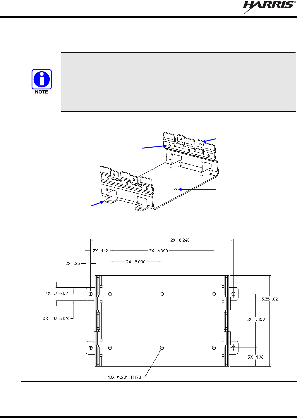
MM-018337-001
32
Typically, both Base Brackets are mounted in the vehicle’s trunk, on the top surface of a trunk tray or the
trunk floor. However, both can be suspended from the trunk’s rear deck if the surface is completely flat,
does not require any shimming and the gauge of deck’s sheet metal is high (16-guage minimum).
The section of the cable which interconnects the DB-44 connector on the rear of the
VRMS7010 to the DB-25 connector on the rear of the VRBS7010 is approximately
eighteen (18) inches long. After the radios are secured within mounted brackets, they
must be located so the respective connectors of the cable can mate to the connectors on
the rear of the radios. Typically, both brackets must be mounted within approximately
twelve (12) inches of each. The brackets/radios may be oriented parallel or
perpendicular to each other.
SIDE & TOP VIEW
TOP VIEW WITH SCREW HOLE DIMENSIONS (In Inches)
Figure 6-1: Base Bracket (Two Required Per VRS7010 Installation)
Side Mounting Tabs
(4 places)
Bracket-To-Vehicle
Mount Surface Screw
Holes (10 places)
Bracket-To-Radio/Filter Screw Holes
(6 places, 3 each side)
Four (4) Upper-Most
Holes (2 each side)
Used to Attach
Extension Brackets

MM-018337-001
33
When installed in a bracket, each radio protrudes several inches from the bracket’s front and back edges.
Therefore, when selecting an exact mounting location, verify sufficient distance at the front and back for
this and additional clearance. A minimum distance of three (3) inches is required from the rear edge of the
bracket; however four (4) inches or more is recommended to improve radio installation and removal ease.
A minimum distance of two (2) inches is recommended from the front edge of each bracket. The bracket
is front/back symmetrical, and left/right symmetrical.
As all installations differ, bracket-to-vehicle mounting screws are not included. The use of #10 stainless-
steel machine screws, stainless-steel flatwashers and stainless-steel self-locking nuts is recommended.
Alternately, #10 stainless-steel self-drilling screws and stainless-steel flatwashers may be used to speed
installation time and/or if the underside of the mounting surface is not easily accessible. Self-drilling
screws such as “TEK” screws do not require drilling of a pilot hole prior to installation. Do not use
common self-threading sheet metal screws because they will loosen over time with vehicle vibrations.
1. Select a location for each Base Bracket—one location for the VRMS7010’s Base Bracket and one
location for the VRBS7010’s Base Bracket. As previously stated, both brackets must be mounted
within approximately twelve (12) inches of each other so the section of the cable which interconnects
the two radios will have sufficient length.
2. Using each Base Bracket (Item 1 in Table 4-2) as a template and/or the dimensional information
shown in Figure 6-1, mark and drill mounting holes into the mounting surface for each bracket. At
least six (6) screws per bracket are recommended for proper installation: Four (4) in the screw holes
of a bracket’s side tabs and two (2) in its center-most screw holes. If the installation prevents the
installation of six screws, a minimum of four screws installed in the side tabs’ holes is required, per
bracket.
3. Deburr all newly drilled mounting holes.
4. Set each bracket in place, and install and tighten the mounting screws.
5. Verify both brackets are firmly secured to the mounting surface. A secure mount prevents
unreasonable vibration, which could damage the radio and/or cause its cable connections to loosen.
6. Attach an Extension Bracket to each side of the VRMS7010’s Base Bracket. Use two #8-32 pan-head
screws per Extension Bracket. These screws are included in the installation kit (Item 3 in Table 4-2).
When tightening the screws, push each Extension Bracket firmly down into the Base Bracket so each
is firm and flush to the other when the screws are tight.
6.2 MOUNT THE RADIOS AND FILTER INTO THE BRACKETS
The radios and the 800 MHz bandpass filter must now be mounted into the brackets as follows:
1. Slide the 800 MHz bandpass filter into the Base Bracket that has the two (2) attached Extension
Brackets. The two (2) RF connectors must face towards the cabling area of the radio installation.
2. Secure the filter to the Base Bracket using three #8-32 pan-head screws (Item 3 in Table 4-2) per side.
Tighten all six (6) screws with a screwdriver until the lock washers on the screws are fully
compressed and the filter is firm and flush between the sides of the bracket.
3. Slide the M7300 mobile radio between the Extension Brackets, just above the 800 MHz bandpass
filter. The rear of the radio must face towards the cabling area of the radio installation.
4. Secure the M7300 mobile radio to each Extension Bracket using six M5 Philips-head screws (Item 4
in Table 4-2), three (3) screws per radio side. These screws have a captive-type (SEMS) lockwasher.
Tighten all six (6) screws with a screwdriver until the lock washer on each screw is fully compressed,
and the filter is firm and flush between the brackets.

MM-018337-001
34
5. Slide the VRBS7010 into the other Base Bracket. The rear of the radio must face towards the cabling
area of the radio installation.
6. Secure the VRBS7010 to this bracket using three #8-32 pan-head screws (Item 3 in Table 4-2) per
side. Tighten all six (6) screws with a screwdriver until the lock washers on the screws are fully
compressed and the radio is firm and flush between the sides of the brackets.
7. Check the mounting area for proper clearance for cable service looping and for air circulation, plus an
area to secure and stow the excess cable lengths.
Proper mounting is one factor that ensures optimal radio performance. An improperly
mounted radio may experience degradation in the quality of voice and data
communications.
MM-018337-001
35
7 ANTENNA INSTALLATION
7.1 ANTENNA MOUNTING LOCATIONS
The VRS7010’s two (2) transmit-receive antennas must be located at least three (3) feet (0.92 meters)
apart. For a standard motor vehicle, the VRMS7010 antenna must be installed at or near the center of the
vehicle’s rooftop, and the VRBS7010 antenna must be installed in the center of the vehicle’s trunk lid.
At this time, review all information presented in the REGULATORY AND
SAFETY INFORMATION section of this manual (begins on page 6). Both
transmit-receive antennas must be installed in accordance with the guidelines
presented in the REGULATORY AND SAFETY INFORMATION section. Use
Table 1-1 and Table 1-2 on page 9 and Figure 7-1 below as a guide for determining
the best possible mounting configuration/location in order to reduce human
exposure to radio frequency (RF) electromagnetic energy during transmit mode.
Antennas must be mounted in locations on the vehicle as illustrated in Figure 7-1 and/or as described in
the following subsections. Also, see Table 4-3 for additional information. Always follow manufacturer’s
instructions when mounting an antenna.
7.1.1 Direct Center or Center-Rear of Rooftop for VRMS7010 Antenna
The center of the vehicle’s roof is the best location for the VRMS7010 antenna (location in Figure
7-1). For optimal performance, the mounting area under the antenna must be flat with a minimum radius
of six (6) inches of metal ground plane. Locating the antenna directly in the center of the roof will
minimize human exposure to RF electromagnetic energy.
If obstructions such as a light bar or another antenna prevent the VRMS7010 antenna from being mounted
in the direct center of the roof, the antenna should be mounted a minimum of one foot away from and
behind the obstruction but in the middle of the roof with respect to the left and right sides of the vehicle
(location in Figure 7-1).
The VRS7010’s two (2) transmit-receive antennas must be located at least three (3)
feet (0.92 meters) apart. See Figure 7-1. The radio-end of each antenna cable must be
labeled so each cable is connected to the correct radio.
7.1.2 Center of Trunk Lid for VRBS7010 Antenna
For a standard motor vehicle, the VRBS7010 antenna should be located in the center of the vehicle’s
trunk lid (location in Figure 7-1). Locating the antenna directly in the center of the lid will provide the
best P25 vehicular repeater mode improve coverage, and minimize human exposure to RF
electromagnetic energy.
The antenna cable of Harris-approved antennas should never be cut to a shorter
length. Instead, excess cable must be tied and stowed. This not only prevents the
antenna from radiating above its intended or configured power, but it also allows
for future installation considerations such as a relocation of the mobile radio
within the vehicle. Installations requiring longer cables are to be treated as
custom and separately specified.
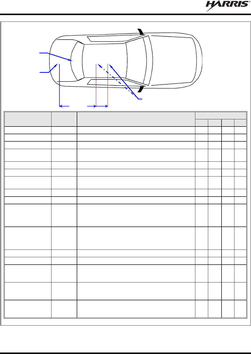
MM-018337-001
36
TOP VIEW OF A TYPICAL VEHICLE
LOCATION
ANTENNA PART
NO.* FOR
RADIO ANTENNA DESCRIPTION
AN-025167-001 VRMS7010 700/800 MHz Standard Rooftop-Mount, 3 dBd Gain
AN-025167-002 VRMS7010 700/800 MHz Elevated-Feed Rooftop-Mount, 3 dBd Gain
AN-025167-004 VRMS7010 700/800 MHz GPS Combo Rooftop-Mount, 3 dBd Gain
AN-025167-005 VRMS7010 700/800 MHz GPS Combo Elevated Feed
Rooftop-Mount, 3 dBd Gain
AN-025167-006 VRMS7010 700/800 MHz Magnetic-Mount, 3 dBd Gain
AN-025167-010 VRMS7010 700/800 MHz Low-Profile Rooftop-Mount, 2 dBd Gain
AN-025167-011 VRMS7010 700/800 MHz GPS Combo Low-Profile
Rooftop-Mount, 2 dBd Gain
AN-025167-014 VRMS7010 700/800 MHz Standard Rooftop-Mount, 5 dBd Gain
AN-025167-015 VRMS7010 700/800 MHz GPS Combo Rooftop-Mount, 5 dBd Gain
AN-125001-002
(mount) with
AN-225001-001
(element)
VRMS7010 700/800 MHz Standard Rooftop-Mount, 3 dBd Gain
AN-125001-002
(mount) with
AN-225001-005
(element)
VRMS7010 700/800 MHz Standard Rooftop-Mount, 5 dBd Gain
AN-025187-001 VRMS7010 GPS Receive Only, Roof-Mount
AN-025187-003 VRMS7010 GPS Receive Only, Magnetic-Mount
AN-125001-002
(mount) with AN-
225001-004 (element) VRBS7010 700/800 MHz Standard Rooftop-Mount, 2 dBd Gain
AN-125001-004
(mount) with AN-
225001-004 (element) VRBS7010 700/800 MHz Thick Rooftop-Mount, 2 dBd Gain
AN-125001-008
(mount) with AN-
225001-004 (element) VRBS7010 700/800 MHz Magnetic-Mount, 2 dBd Gain
* See Table 4-3 on page 23 for the respective antenna catalog numbers.
Figure 7-1: Required Antenna Mounting Locations with Antenna Part Numbers
Trunk Lid Rooftop
Hood
3-Feet
Minimum
Antenna
Separation
V
RBS701
0
Antenna
GPS Antenna
(if required;
see text)
V
RMS7010 Antenna — Use location (center-
most location) unless an obstruction such as a
light bar or another antenna is nearby. See text.
MM-018337-001
37
7.1.3 Rear Deck Lid for GPS Stand-Alone GPS Receive Antenna
If the VRMS7010 does not use a GPS combination-type antenna and it is equipped with a GPS receiver, a
stand-alone GPS receive antenna must be separately located and mounted. The vehicle’s rear deck lid
(location in Figure 7-1) is the recommended mounting location for this case. This locates the GPS
antenna inside the vehicle.
7.2 ANTENNA INSTALLATION PROCEDURE
Antennas must be installed before completing the radio installation.
7.2.1 Install and Connect Mobile Antennas
Table 4-3 (page 23) and Figure 7-1 (page 36) list several types of mobile radio antennas available for use
with the radio. As presented in the previous section, various mounting locations exist.
1. After selecting antenna mounting locations, refer to the antenna manufacturer’s assembly, mounting
and testing instructions included with the antenna kit for installation guidance. If necessary, contact
the Technical Assistance Center (see page 19 for contact information).
2. Route each antenna cable from the antenna to the rear of the respective radio. Keep each cable out of
casual contact areas from persons and objects within the vehicle. Tie and stow as necessary to protect
the cables.
3. Label the radio-end of each antenna cable. The cable from the rooftop-mounted antenna (highest of
the two) should be labeled “VRMS7010 Ant.” and the cable from the trunk-mounted antenna (lowest
of the two) should be labeled “VRBS7010 Ant.”
Use the full length of coaxial cable included with each antenna. Never cut the
cable to a shorter length, but rather coil any excess. Reducing the length of cable
increases the output power radiated by the antenna, thereby exceeding the
Maximum Permissible Exposure (MPE) allowance regulated by the FCC.
CAUTION
The VRS7010 installation’s VRMS7010 and VRBS7010 antennas are not
interchangeable. Therefore, label the radio-end of each cable for future reference,
as described in step 3.
4. Using an appropriate crimp tool, crimp the supplied TNC RF connector to the end of each antenna
cable. See Figure 7-2 for crimping instructions.
5. Connect each antenna cable’s TNC plug-type (male) connector to the respective radio’s TNC
receptacle-type (female) RF connector at the rear of the radio. The VRMS7010 antenna cable (labeled
“VRMS7010 Ant.”) must be connected to the “ANTENNA” connector on the rear of the 800 MHz
bandpass filter. The VRMS7010 antenna cable (labeled “VRBS7010 Ant.”) must be connected to the
“pigtail” type antenna cable of the VRBS7010. Mate the connectors and turn the plug clockwise until
finger-tight.
This will be a temporary connection until the radios and antennas can be tested after the installation is
complete (in accordance with test procedures presented in Section 16). The antennas should be connected
now in case of accidental transmission.
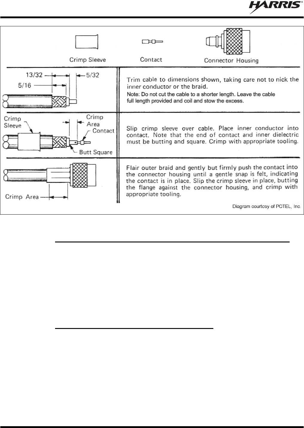
MM-018337-001
38
(VS-AN-025167-010 Rev. A)
Figure 7-2: Crimping Instructions for TNC RF Connector (Actual Size; Dimensions in Inches)
7.2.2 Connect RF Cable Between VRM Radio and 800 MHz Bandpass Filter
A RF cable must be connected between the antenna connector of the M7300 and the 800 MHz bandpass
filter as follows:
1. Obtain RF Cable CA-018378 from the installation kit (item 8 in Table 4-2).
2. Mate the cable’s male TNC connector the radio’s female TNC connector. Do not fully tighten at this
time.
3. Mate the cable’s female TNC connector to the 800 MHz bandpass filter’s male TNC connector.
4. Using a pair of soft-jaw pliers, firmly tighten both of the cable’s TNC connectors. Do not overtighten.
7.2.3 Install and Connect GPS Antenna (If Required)
The VRMS7010’s M7300 mobile radio may be equipped with an internal GPS receiver. If so, this
receiver requires connection to an externally-mounted GPS antenna if the GPS functions will be utilized.
Some installations may use a magnetic-mount stand-alone GPS antenna installed separately from the
SMR mobile antenna.
The following antenna installation procedure is recommended:
1. Once the mounting location is selected, refer to the antenna manufacturer’s mounting and testing
instructions for installation guidance. If necessary, contact the Technical Assistance Center (see page
19 for contact information).
2. Route the cable from the GPS antenna to the rear of the radio. The cable should be kept out of casual
contact from persons within the vehicle.

MM-018337-001
39
3. Connect the GPS antenna cable’s SMA plug-type (male) connector to the radio’s SMA receptacle-
type (female) “pigtail” type RF connector at the rear of the radio. Mate the two connectors and turn
the plug clockwise. Tighten using two 5/16-Inch combination or open-end wrenches. Do not over-
tighten.
Do not alter the length of cable from the GPS antenna. The SMA connector on the end
of the antenna cable is not field-replaceable. Tie and stow excess cable as necessary.
The GPS combo antenna kit includes a GPS antenna built into the base of the mobile antenna. No extra
holes are required for the GPS cable when using this antenna. The antenna must be kept at least six (6)
inches away from any other antenna mounted on the vehicle and have at least six inches of surface ground
plane beneath it.
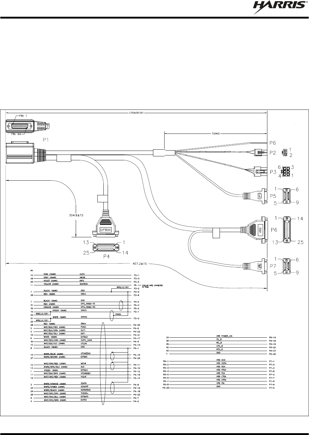
MM-018337-001
40
8 INTERFACE CABLE INSTALLATION
8.1 INTERFACE CABLE CA-012349-003 OVERVIEW
Interface Cable CA-012349-003 interconnects the VRMS7010 to the VRBS7010. It also provides
connections for various optional equipment, if necessary. The cable interconnects the 44-pin I/O
connector on the rear of the VRMS7010 to the 25-pin connector at the rear of the VRBS7010. For
connection of optional equipment, the cable breaks out into several smaller standardized connectors,
allowing straightforward access to external I/O interfaces provided by the VRMS7010. The cable is
shown in Figure 8-1 below. The cable’s installation procedure is included on page 42.
MILLIMETERS
MILLIMETERS
MILLIMETERS
MILLIMETERS
(Made From PS-CA-012349 Rev. D)
Figure 8-1: Interface Cable CA-012349-003
MM-018337-001
41
P1, the cable’s 44-pin D-subminiature (DB-44) connector mates with the connector on the rear of the
VRMS7010.
P2, the cable’s 2-pin connector, is not used.
P3, the cable’s 6-pin connector, is a connector for basic accessories (e.g., hookswitch, etc.).
P4, the cable’s female D-subminiature 25-pin (DB-25) connector, provides audio and data connections for
optional equipment such as an external siren and light system (e.g., Federal Signal SS2000 SmartSiren®).
P5, the cable’s D-subminiature 9-pin (DB-9) connector, provides NMEA-formatted GPS serial data
connections for the external computer processing the NMEA-formatted GPS data received by the GPS
receiver within the VRMS7010 (M7300 mobile radio). See Section 14 on page 63 for additional
information.
P6, the cable’s male D-subminiature 25-pin (DB-25) connector, mates to the female 25-pin
D-subminiature connector of the VRBS7010. These interconnections provide the audio and digital control
paths between the VRMS7010 and the VRBS7010.
Table 8-1: Interface Cable CA-012349-003 Option Connectors’ Interconnections
44-PIN I/O
CABLE
CONNECTOR
P1 PIN
SIGNAL NAME TO/FROM DESCRIPTION
19 SPKR1
20 SPKR1
P2 pin 1 Speaker Audio Output 1
(Not used in a VRS7010 installation)
21 SPKR2
22 SPKR2
P2 pin 2 Speaker Audio Output 2
(Not used in a VRS7010 installation)
10 OUT2 P3 pin 1 Digital Output 2 (open-collector)
7 GND P3 pins 2 & 4 Chassis Ground
(fused on VRM radio’s PK Board at 3.15 amps)
26 HKSW P3 pin 3
Digital Input for Hookswitch (default) or for radio PTT.
Active = Ground. Inactive = Open. For use as a PTT input
with OpenSky “rear panel software” R15A and later, send
the following AT command to the VRM radio:
AT@PTT_INPUT2. Also see P4 pin 21.
25 INP2 P3 pin 5 Digital Input 2
28 SWA+ P3 pin 6 Switched A+ (DC Power) Output
8 GND P4 pin 1 Chassis ground (fused on PK Board at 3-amps)
30 DGPS_DATA P4 pin 4 GPS Receiver Module DGPS Correction Data Serial Data
Input (NMEA-Formatted)
4 EXTRX P4 pin 5 External Rx Audio Output
9 EXTMOD P4 pin 7 External Tx Audio Input
3 SDATA P4 pin 8 See footnote 3.
5 FDISC P4 pin 9 Buffered Discriminator Audio
13 ALO P4 pin 10 Audio Ground/Reference
(fused on VRM radio’s PK Board at 3.15 amps)
3 This pin on the radio’s DB-44 connector should not be used. It is not functional. Instead, use the respective pin on the
CH-721 Option Cable’s female DB-25 pin connector. See Section 13.2 for additional information.

MM-018337-001
42
Table 8-1: Interface Cable CA-012349-003 Option Connectors’ Interconnections
44-PIN I/O
CABLE
CONNECTOR
P1 PIN
SIGNAL NAME TO/FROM DESCRIPTION
12 MICHI P4 pin 11
1 EXTALO P4 pin 12 See footnote 3.
14 VOLHI P4 pin 13 Volume High
15 CTLON P4 pin 14 Control-On Digital Input. Not used.
16 XTONEENC P4 pin 15
External Tone Encode Audio Input (default) or Auxiliary
Mic Audio Input. For use as an aux mic audio input with
OpenSky “rear panel software” R15A and later, send the
following AT command to the VRM radio:
AT@MIC_REAR_INPUT2. Also see P4 pin 24.
17 XTONEDEC P4 pin 16 External Tone Decode Audio Output
6 EXTALO P4 pin 17 External Audio Output (Balanced, Low)
24 HORNRING P4 pin 18 See footnote 3.
23 SONOFF P4 pin 19 See footnote 3.
18 INP1 P4 pin 21
Digital Input 1. Active = Ground. Inactive = Open. For use
as a PTT input with OpenSky “rear panel software” R15A
and later, send the following AT command to the VRM radio:
AT@PTT_INPUT1. Also see P3 pin 3.
2 OUT1 P4 pin 22 Digital Output 1 (open-collector)
29 TXENB+ P4 pin 23 Transmit Enable B+.
27 EXTMIC P4 pin 24
External/Auxiliary Mic Audio Input. For use as an aux mic
audio input with OpenSky “rear panel software” R15 and
later, send the following AT command to the VRM radio:
AT@MIC_REAR_INPUT1. Also see P4 pin 15.
28 SWA+ P4 pin 25 Switched A+ DC Power Output.
32 GPS_NMEA_RX P5 pin 2 GPS Receiver Position Data Serial Data Output
(NMEA-Formatted)
31 GPS_NMEA_TX P5 pin 3 GPS Receiver Module Initialization Data Serial Data Input
(NMEA-Formatted)
7 GND P5 pin 5 Ground for GPS Serial Data Signals
(fused on VRM radio’s PK Board at 3.15 amps)
11 IGNITION (no connection) Unused/Spare ignition sense input
33 — 44 — P6 These pins provide the interface between the VRMS7010
and the VRB. See the maintenance manual for additional
information.
8.2 INTERFACE CABLE CA-012349-003 INSTALLATION PROCEDURE
Follow this procedure to install the Interface Cable:
1. Obtain Interface Cable CA-012349-003. It is included in the installation kit.
2. Mate the cable’s male 44-pin D-subminiature (DB-44) connector to the female 44-pin D-subminiature
connector on the rear of the VRMS7010. Using a screwdriver, tighten the two jackscrews securely.

MM-018337-001
43
3. Mate the cable’s male D-subminiature 25-pin (DB-25) connector (labeled VRB) to the VRBS7010’s
female 25-pin D-subminiature connector. Using a screwdriver, tighten the two jackscrews securely.
4. Tie and stow the cable.
MM-018337-001
44
9 DC POWER INSTALLATION
Refer to the wiring diagram at the end of this manual as necessary when performing wiring procedures
presented in this section.
9.1 OVERVIEW OF ON/OFF POWER WIRING CONFIGURATIONS
Radio on/off power control is accomplished by the control head. When the control head is turned on, it
“wakes-up” the VRMS7010 via data activity on the CAN link. The VRMS7010 automatically powers-up
the VRBS7010 when the P25 vehicular repeater mode is enabled. The following power wiring
configurations are supported:
Radio turns on and off automatically with vehicle’s ignition switch/key — This configuration
allows the on/off state of the vehicle’s ignition switch/key to control the on/off power state of the
radio. The white wire of the control head’s DC Power Cable is connected to a fused switched power
source, typically identified as vehicle “Accessory” power. This source must switch on (up to positive
(+) battery voltage potential) when the vehicle’s ignition switch/key turns on, and it must switch off
(to near zero volts) when the ignition switch/key turns off. The required fuse rating is 3 amperes.
When using this configuration, the CH-721 control head’s on/off/volume control must be left in the
on position for automatic power-up/down to function properly.
Radio turns on and off with a manual switch — This configuration is used when, for example, the
radio must remain on even when the ignition key must be removed from the vehicle and a separate
on/off switch is acceptable. The white wire of the control head’s DC Power Cable is connected to one
side of a manually-controlled switch, and the other side of this switch is connected to unswitched and
fused vehicle power. The required fuse rating is 3 amperes. When using this configuration, the
CH-721 control head’s on/off/volume control must be left in the on position for automatic power-
up/down to function properly.
Radio turns on with control head’s on/off/volume control (“hot wired”) — This configuration
allows radio on/off power control only via the control head’s on/off/volume control. It may be desired
if, for example, the radio must remain on even when the ignition key must be removed from the
vehicle and a separate on/off switch is not desired and/or not acceptable. The white wire of the
control head’s DC Power Cable must be connected to unswitched and fused vehicle power. The
required fuse rating is 3 amperes.
The VRMS7010, the VRBS7010, and the control head require separately-fused main DC power. This is
the red wire of each DC power cable. The switch power source to the control head is also separately
fused. This is the white wire of the control head’s DC power cable. In-line type fuses and fuse holders are
utilized.
CAUTION
Any DC input power provided to the radio shall be no higher or lower than
13.6 volts DC 10%. The DC input power should be free and clear of any AC noise or
DC spikes above 18 volts. If the vehicle cannot meet these requirements, then DC
conditioning will be required before any DC power is connected to the radio. This
includes conditioning for both the radio’s main DC power input lead and for its
switched ignition sense power input. DC conditioning can be accomplished by a noise
filter or DC isolation equipment such as Harris part number FL-018314-001 or FL-
018314-002, or similar units with equal specifications. The fuse must be placed in-line
before any noise filter. Contact TAC for additional information.
MM-018337-001
45
9.2 POWER INSTALLATION PROCEDURE
9.2.1 Radio DC Power Cables and Main Fuse Holders Installation
Each radio DC power cable has a 3-pin connector, a 20-foot red wire for the main power connection, a
20-foot white wire which is not used/not connected in this application, and a 4-foot black wire for the
ground connection. Each cable is supplied with AGC-type waterproof fuse holders, AGC-type fuses, and
non-insulated ring terminals. The following installation procedures are recommended:
9.2.1.1 Black Wire Connections (Ground Wires)
1. Obtain two (2) DC Power Cables, part number CA-012365-001. These cables are included in the
installation kit.
CAUTION
Do not confuse the radios’ DC Power Cables which each has a 10-AWG red wire with
the control head’s DC Power Cable which has a 12-AWG red wire. The radios require
much more DC operating current than the control head. Therefore, each radio requires
the larger size (10-AWG) wire. Control head DC Power Cable installation procedures
are included in Section 10 of this manual.
2. Connect one DC Power Cable to the VRMS7010 by mating its 3-pin connector to the VRMS7010’s
3-pin DC power cable connector. Visually align the key and firmly push and turn the outer locking
ring clockwise until it stops. A click will be sensed to confirm proper mating.
3. Connect the other DC Power Cable to the VRBS7010 using the same connection method.
4. Prepare to connect both cables’ black wires to vehicle ground by locating an area of vehicle
metal within approximately three (3) feet of the two radios. This surface must have a solid and
stable connection to vehicle ground (i.e., battery ground).
CAUTION
The radios must have a solid and stable ground connection to vehicle ground. If
there is no well-grounded metal surface within approximately three (3) feet of the
radios, a metal grounding strap or a heavy-gauge wire (with proper wire
terminals) must be added between the metal surface and a solid and stable vehicle
grounding point, preferably near the battery. Some vehicles are equipped with a
high-current DC power access point (a vehicle option) that provides high-current
power and ground studs, typically in the vehicle’s trunk area. In this case, the
ground stud of the power access point can be considered a good vehicle ground,
and used as such. Metal surfaces should be stripped of all paint and dirt to expose
bare metal before attaching a grounding strap or wire terminal. To make all
ground connections, the use of stainless-steel hardware with machine-screw
threads, shelf-locking nuts and washers is recommended.
5. Strip the area of any paint or dirt to expose a bare metal surface, approximately ¾-inch square.
6. Drill a hole in the approximate center of the bare metal surface, and deburr it. A ⅜-inch non-
insulated ring terminal is supplied with each cable to make the ground connection. Therefore, hole
diameter should be appropriate for the utilized grounding screw/bolt size and type used to connect the
ring terminals to the bare metal surface. This hardware is not supplied.
7. Cut the two (2) black wires to the required length plus some additional length for service loops in
each wire, then strip insulation back approximately ¼-inch.
8. Crimp a ⅜-inch non-insulated ring terminal (supplied with the cable) to the end of each black wire.
MM-018337-001
46
9. Attach the two (2) ring terminals with black wires to the bare metal surface using stainless-steel self-
locking hardware (i.e., machine screws with washers and locking nuts) or other appropriate hardware
to ensure a reliable terminal-to-metal contact. Tighten securely.
10. Apply an approved paint or rust-inhibitor over the remaining exposed bare metal surface and around
the ring terminal. Do not use an acid-based sealant.
9.2.1.2 Red Wires and Main Fuse Holder Connections (Radios’ Main Power Wires)
1. Continue installation of two (2) DC Power Cables by routing their 20-foot 10-AWG red wires to the
location of the vehicle’s battery (or its main DC bus bar or stud). Route the wires through channels in
the vehicle to the location of the battery. Remove interior panels, door kick panels, etc., as necessary.
Protect the wires from possible chafing where necessary. Tie and stow it as necessary.
The white wire of both radios’ DC Power Cables require no electrical connection.
Rather than be cut from the two cables, it is recommended that these wires be routed up
to the vehicle’s fuse box, coiled, labeled, and stowed for possible future use. The white
wire of the control head’s DC Power Cable is the radio installation’s ignition sense
input for on/off power control of both the control head and radio. Radio on/off power
control is accomplished by the control head. The control head “wakes-up” the
VRMS7010 via data activity on the CAN link.
CAUTION
Plan the routing of the two 10-AWG red wires carefully, using an existing access hole
in the vehicle’s firewall if possible. Alternately, drill a new hole approximately 3/8-inch
in diameter and install a small rubber grommet to protect the wires from chafing on the
hole’s sharp metal edge. To prevent fumes from entering the passenger
compartment, this hole/grommet/wire combination must also be sealed with a
silicon-based sealer before completing the installation.
CAUTION
Do not install any wiring or fuse holder over or in the near vicinity of the vehicle’s
engine. Excessive engine heat can cause permanent damage to these components and
can lead to intermittent electrical connection to the battery.
2. Obtain two (2) waterproof inline fuse holders (HFB type) included with the DC Power Cables.
3. Observe and abide by the following WARNING!
4. Cut the red wires to the required lengths for connection to the battery’s positive (+) battery terminal
(or the main DC bus bar or stud).
5. Prepare to splice the two (2) inline fuse holders into the red wires by cutting the red wires again, at
approximately three (3) to six (6) inches from each end.
6. Strip all wire ends back approximately ⅜-inch each, place a fuse holder shell on each wire, and
securely crimp a fuse holder terminal to each wire end. Before crimping, verify fuse holder shells are
oriented in the correct directions (i.e., with each large end towards the wire end).

MM-018337-001
47
Before making connections to the battery’s positive post, carefully disconnect the
battery’s negative (ground) cable(s). This will prevent tools or other metallic
objects which come in contact with the battery’s positive terminal from shorting to
vehicle ground, causing sparks or even a fire or an explosion! When disconnecting
the negative cable(s), cover/insulate the positive post(s) if it is not already so a tool
cannot short between the posts. Some vehicles, such as those with diesel engines
have more than one battery; in this case, disconnect the negative cables at all
batteries.
Radio and control head fuses should not be installed until all wiring is complete.
This will prevent the radio from powering up prematurely and/or causing an in-
rush of current that could lead to shorting of the battery, sparks, or even fire.
7. Label each fuse holder and red wire appropriately (e.g., “VRS7010 VRMS7010: 15-AMP FUSE” and
“VRS7010 VRBS7010: 15-AMP FUSE”).
8. Do NOT install fuses into the fuse holders at this time.
9. Crimp an appropriate electrical terminal to each short red wire. A ⅜-inch ring terminal is included
with each cable for this purpose, but another terminal type (not supplied) may be used if required.
10. Connect both ring terminals directly to the battery’s positive post, or if present, to a stud on the
battery’s main/non-switched power distribution terminal block.
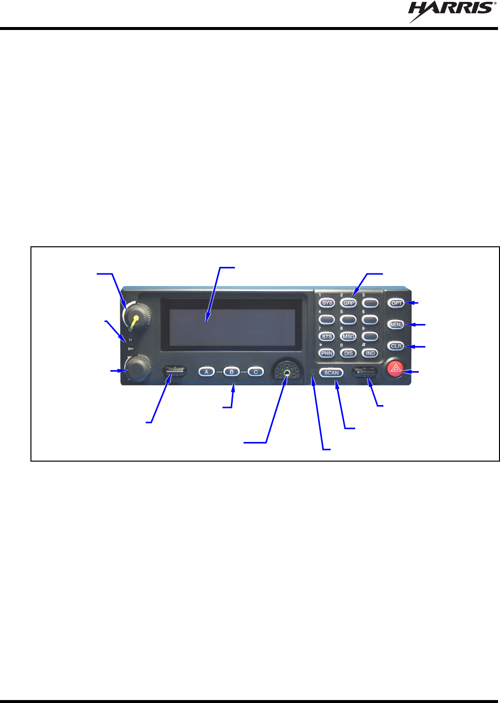
MM-018337-001
48
10 CONTROL HEAD INSTALLATION
10.1 GENERAL INFORMATION
Since the VRS7010 is a remote-mount mobile radio, it must be connected to a control head to provide the
operator-to-radio interface. The CH-721 System model control head is used with the VRS7010.
The front panel of the CH-721 System mode control head is shown in Figure 10-1. This control head has
a large 3-line graphical vacuum-fluorescent display, front panel controls and buttons for user control of
the mobile radio, an internal high-power audio amplifier to drive an externally-connected speaker, and a
front panel microphone connector. It features a 12-key numeric keypad that provides Dual-Tone Multi-
Frequency (DTMF) keypad functionality and easier operator system/group selection, three (3) preset
buttons, and an emergency/home button. Other front panel components include a microphone connector
and LED-type indicators. One LED indicator is the busy indicator that lights when the radio is receiving a
call and one is the transmitter-enabled indicator that lights when the radio is transmitting. The front panel
also has an ambient light sensor for automatic display dimming.
Figure 10-1: CH-721 System Model Control Head Front Panel
Figure 10-2 illustrates the control head’s rear panel. Connectors on the rear panel include two (2) CAN
port connectors, a speaker audio (output) connector and a 25-pin D-subminiature (DB-25) accessory
connector, and a 9-pin D-subminiature (DB-9) serial port connector. The DB-25 accessory connector is
used for connection of optional equipment to the control head, such as a siren/light control system. The
DB-9 serial port connector is typically only used during programming performed at the factory.
Clear Button
Menu Button
Option Button
On/Off/
Volume
Control
System/Group
Knob
Transmit
and Busy
Indicators
/ Ramp Control
Preset
Buttons
3-Line Graphical Vacuum
Fluorescent Display
Microphone Connecto
r
+/- Ramp Control
Ambient Light-Level Sensor
Scan On/Off Button
12-Ke
y
Ke
y
pad
Emergency/
Home Button
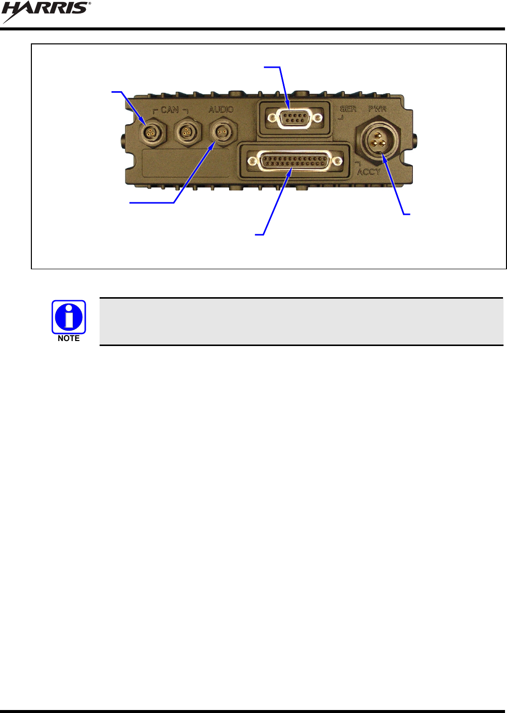
MM-018337-001
49
Figure 10-2: CH-721 Rear Panel
Prior to installing the control head, verify it has the proper software version installed and
verify it has been properly configured for customer use.
CAN Port
Connectors
(2 places)
Speaker Audio
Connecto
r
Serial Port Connecto
r
(DB-9)
DC Power
Connector
Accessory Connecto
r
(DB-25) Note: Serial and Accessory connectors are
shown without waterproof covers.
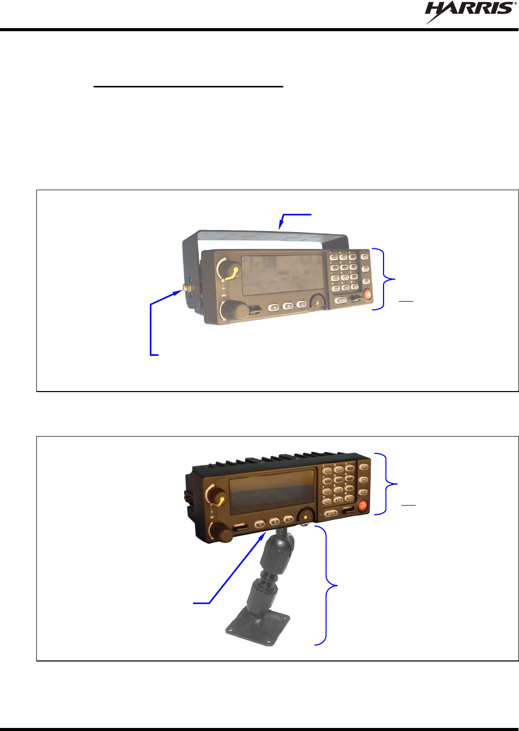
MM-018337-001
50
10.2 CONTROL HEAD MECHANICAL INSTALLATION
10.2.1 Selecting the Mounting Location
When selecting a location for the CH-721 control head, first observe the safety and operator-convenience
related information presented in Section 5.1 on page 27. Also always consider and include clearance for
the microphone’s connector that must mate to the mic connector on the front panel of the head, and
clearance for the connectors/cables that must mate to the connectors on the rear panel of the head. The
CH-721 control head can be mounted under or on top of a mounting surface (typically the vehicle’s dash)
as space permits using either the standard U-shaped mounting bracket or the optional mounting pedestal.
Figure 10-3: Standard U-Shaped Control Head Mounting Bracket (Kit Part Number KT-008608)
Figure 10-4: Optional Control Head Mounting Pedestal (Part Number MACDOS0012)
Mounting Bracket
(Shown positioned above control head)
Control Head Mounting
Pedestal MACDOS0012
(Pedestal can be attached to the
bottom of the head, as shown, or it
can be attached to the top of the
head.)
Bracket shown
attached to a CH-721
System model
control head (Head is
not included with
Mounting Bracket Kit.)
Pedestal shown
attached to a CH-721
System model
control head (Head is
not included with
Mounting Pedestal.)
Socket-Head Cap (Allen) Screw, Lockwasher and Flat
Washer; 2 places each side (Included with kit)
#8-32 Pan-Head Screw; 4
places (Included with
Mounting Pedestal)
For a “hanging” control head
installation, the pedestal can
be attached to the top of the
head via threaded holes in
the top of the head’s case.
This figure shows the
pedestal attached to the
bottom of the control head via
threaded holes in the bottom
of the case.
MM-018337-001
51
10.2.2 Using the Standard U-Shaped Mounting Bracket
If the standard U-shaped Mounting Bracket will be used to mount the control head, the following
mounting procedure is recommended. This bracket is included with the Mounting Bracket Kit listed in
Table 4-2 (on page 21).
1. Using the Mounting Bracket as a template, mark and drill mounting holes into the mounting
surface as required. The round and elliptical holes in the bracket’s vehicle mounting surface are
symmetrical so forward/backwards positioning is not important during this step. However,
positioning is important in the next step.
CAUTION
When drilling holes, be careful to avoid damaging some vital part of the vehicle (fuel
tank, transmission housing, etc.). Always check to see how far the mounting screws
will extend below the mounting surface prior to installation. After drilling pilot holes,
remove all metal shavings from them (i.e., deburr the holes) before placing the bracket
and installing the mounting screws.
2. Postion the bracket at the mounting surface so the two round holes in its two side “ears” are
nearest to the normal location of the operator (typically towards the rear of the vehicle) and the
two slotted holes are farthest from the normal location of the operator (typically towards the front
of the vehicle).
3. Install and tighten the mounting screws. Screws for mounting the bracket to the mounting
vehicle’s surface are not included, as all installations differ. Self-tapping screws are
recommended. Do not use common self-threading sheet metal screws because they will loosen
over time with vehicle vibrations.
4. Verify the bracket is held firmly to the mounting surface. Firm mounting prevents unreasonable
vibration, which could damage the control head and/or cause its cable connections to loosen.
5. Slide the control head into the bracket, placing the two pegs protruding from its left and right
sides into the respective round holes in the bracket’s two side “ears.”
6. In each side “ear” of the mounting bracket, start a #8-32 socket-head cap (Allen) head screw with
a lockwasher and a flat washer by inserting the screw through the slotted hole in the bracket and
then into the threaded hole in the side of the control head. This hardware is included with
Mounting Bracket Kit. The lockwasher should be adjacent to the screw head and the flat washer
should be adjacent to the bracket. Turn each screw clockwise as observed from the head of the
screw.
7. The control head can be positioned at various angles for best display viewing at the normal
position of the operator. As necessary, turn it on the pegs to a good position and tighten both
screws using an 1/8-inch hex key (Allen) wrench until the control head is held firmly in place. Do
not over-tighten.
10.2.3 Using the Mounting Pedestal (Optional)
An optional Mounting Pedestal, part number MACDOS0012, may be purchased separately to replace the
standard U-shaped Mounting Bracket. This pedestal can be attached to the bottom of the control head as
shown in Figure 10-4 and then mounted to a mounting surface below the two. It can also be attached to
the top of the head and then mounted to a mounting surface above the two.
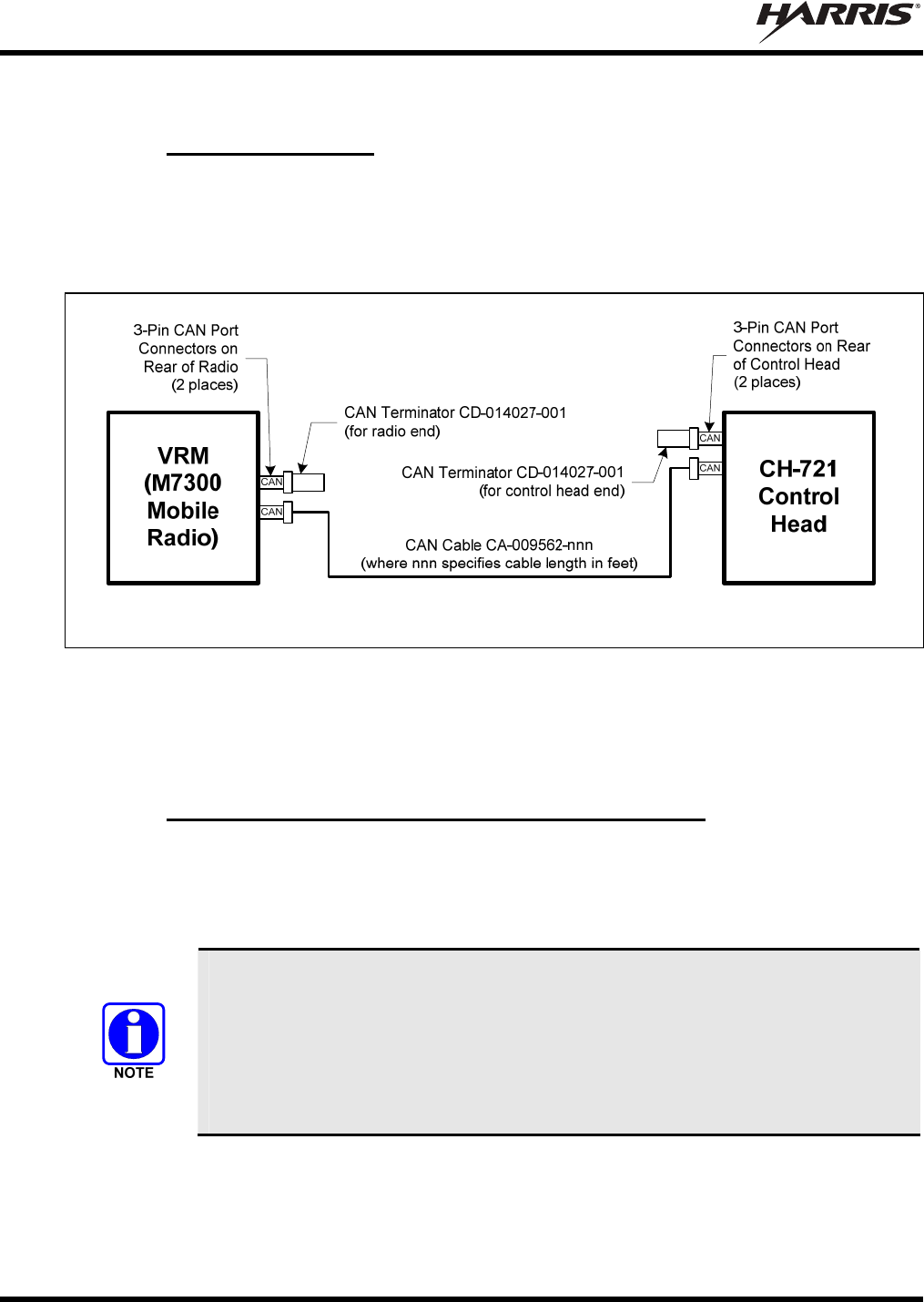
MM-018337-001
52
10.3 CAN CONNECTIONS
10.3.1 General Information
The installation requires a CAN cable between every two “CAN devices” and CAN terminators on each
end of the CAN link. The VRS7010’s VRMS7010 is considered a CAN device, and each CH-721 control
head in the installation is also considered a CAN device. Figure 10-5 illustrates CAN cable and CAN
terminator connections. Because CAN devices do not have internal terminators, the CAN link must be
terminated at both ends via a CAN terminator.
For Available CAN Cable Lengths and Respective Part Numbers, see Table 4-4 on page 25
Figure 10-5: CAN Cable and Terminator Connections
Both the VRMS7010 and the control head have two CAN ports. Figure 5-1 on page 28 shows the radio’s
two CAN port connectors, which are located on cable side of the I/O cable’s DB-44 connector. Figure
10-2 on page 49 shows the two ports on the control head’s rear panel.
10.3.2 Make CAN Link Terminations and Cable Connection
Follow this procedure to complete CAN cable connections:
1. Connect the CAN Terminator (Item 11 listed in Table 4-2 on page 21) onto either one of the two
smaller 3-pin connectors on the rear of the CH-721. This action makes the CAN termination at the
control head end of the CAN link.
When mating any CAN connection (terminators and cables), visually align the
¾-moon-shaped keys of the connectors, and then gently push and turn the outer
locking ring of the plug (male) connector clockwise until it stops. A mild click will be
sensed to confirm proper mating. Without visual alignment as a guide, it is possible
with excessive force to mate the CAN connectors improperly. Damage to the
connector(s) may result. Therefore, visual alignment is recommended when mating
CAN connectors.
2. Route the CAN Cable (Item 9 listed in Table 4-2) through the vehicle’s interior wire/cable channeling
to the VRMS7010. Remove interior panels, door kick panels, etc., as necessary. Protect the cable
from possible chafing as necessary.
3. Attach the CAN Cable’s connector to one of the two CAN port connectors on the VRMS7010’s I/O
cable.
MM-018337-001
53
4. Connect the other end of the CAN Cable to the open CAN port connector at the rear of the control
head.
5. Connect the CAN Terminator (Item 11 in Table 4-2) onto either one of the two smaller 3-pin
connectors on the VRMS7010’s I/O cable. This action makes the CAN termination at the radio end of
the CAN link.
6. Loop, tie and stow the excess cable as necessary.
10.4 CONTROL HEAD POWER CABLE INSTALLATION
Plan the route of the control head’s DC Power Cable carefully. Do not route the cable where it will be
damaged by heat sources or by casual contact, and protect it from wire chafe per standard installation
methods. The following procedures are recommended:
10.4.1 Install DC Power Cable and Make Power and Ground Connections
1. Connect the control head’s DC Power Cable (Item 6 listed in Table 4-2 on page 21) to the large 3-pin
connector at the rear of the head. Visually align the key and gently push and turn the outer locking
ring clockwise until it stops. A click will be sensed to confirm proper mating.
2. At the back of the control head, locate a nearby section of vehicle chassis ground and strip this area of
any paint or dirt to expose a bare metal surface.
3. Cut the black wire of the control head’s DC Power Cable to the required length, plus a service loop of
at least six (6) inches, then strip it and crimp a ⅜-inch ring terminal to it. Two (2) ring terminals of
this type are included with the cable.
4. Drill a hole as necessary and attach this ring terminal to chassis ground. Use stainless-steel self-
locking hardware (i.e., machine screws with washers and locking nuts) or other appropriate hardware
to ensure a reliable terminal-to-metal contact. Tighten securely.
CAUTION
The control head must have a solid and stable ground connection to vehicle
ground. If there is no well-grounded metal surface within approximately four (4)
feet of the control head, the DC Power Cable’s black wire should be extended to a
solid and stable vehicle grounding point, preferably near the battery. Some
vehicles are equipped with a high-current DC power access point (option) that
provides high-current power and ground studs, typically in the vehicle’s trunk
area. In this case, the ground stud of the power access point can be considered a
good vehicle ground, and used as such. Metal surfaces should be stripped of all
paint and dirt to expose bare metal before attaching a ground wire. To make all
ground connections, the use of stainless-steel hardware with machine-screw
threads, shelf-locking nuts and washers is recommended. To extend the length of
the ground wire, use at least 12-AWG wire and approved wire splicing
techniques.
5. At the back of the control head, tie and stow the cable as necessary.
6. For the positive 12-volt DC main power source connection, route the cable’s red wire to the location
of an unswitched 12-volt DC power source, typically near the vehicle’s battery. Remove interior
panels, door kick panels, etc. Protect the wire from possible chafing as necessary. This is the control
head’s main DC power source.
7. Obtain one of the waterproof inline fuse holders (HFB-type) included with the control head’s DC
Power Cable.
MM-018337-001
54
8. Cut excess length from the red wire and splice the fuse holder into it, near the location of the
unswitched 12-volt DC power source connection point.
9. Label this fuse holder and red wire appropriately (e.g., “CH-721 Main Power: 5-AMP FUSE”).
10. Using an appropriate electrical terminal, connect the red wire to the unswitched DC power source. A
⅜-inch ring terminal is included with the cable for this purpose, but another terminal type (not
supplied) may be used if required.
11. Obtain the 5-amp AGC fuse included with the cable, and install it into the fuse holder.
Do not share the control head’s fuse with any other device. Doing so can cause excess
current to flow through the fuse, causing it to blow unnecessarily.
CAUTION
The fuse rating for the control head’s red wire is 5 amperes. The 3-amp fuse included
with the cable must not be used for fusing the control head’s main DC power. It fuses
the head’s white wire.
10.4.2 Connect DC Power Cable’s White Wire
A review of the information presented in Section 9.1 (page 44) may be beneficial at this time. As required
per the chosen power-up configuration, connect the white wire by following one of the three procedures
presented in the respective sub-section that follows.
Only the control head’s white wire must be connected to the ignition or switched
power sense. When this vehicle line is asserted (i.e., power switched on), the control
head automatically powers-up the VRMS7010 via the CAN connection.
10.4.2.1 Control Head and Radio Turn on with Vehicle’s Ignition Switch/Key
With this wiring configuration, the control head and the VRMS7010 automatically turn on and off with
the vehicle’s ignition switch/key. The white wire of the control head’s DC Power Cable is sometimes
referred to as the “white ignition switch wire” or the “ignition sense input wire.” In this configuration, the
white wire connects to a switched power source, typically identified as “Accessory” power, that switches
on and off with the vehicle’s ignition switch/key. When using this configuration, the CH-721 control
head’s on/off/volume control must be left in the on position for automatic power-up/down to function
properly.
The white ignition sense wire must be connected to a power source that switches from
approximately zero volts to approximately +13.6 volts when the vehicle’s ignition
switch/key is turned from the OFF position to the ACCESSORY and RUN positions.
Use of a switched power source that is subject to voltage changes as a result of other
actions, such as opening a vehicle door, may result in undesirable radio operation and/or
a degradation of radio performance.
1. Locate the vehicle’s switched ignition or “Accessory” power connection point that will be used for
the switched ignition 12-volt DC power source. This point is typically located at or near the vehicle’s
fuse panel. It may be necessary to consult the vehicle manufacturer’s wiring diagram.
MM-018337-001
55
2. Route the white wire of the control head’s DC Power Cable from the back of the head to the area near
this connection point. Protect the wire from possible chafing as necessary.
3. Obtain one of the waterproof inline fuse holders (HFB-type) included with the control head’s DC
Power Cable or see the following NOTE.
4. Cut excess length from the white wire and splice the fuse holder into it, near the location of the
connection point.
5. Using an appropriate electrical terminal, connect the white wire to the switched power connection
point. An open-barrel spade terminal is included with the cable for this purpose, but another type of
terminal (not supplied) may be used as required.
6. Obtain the 3-amp AGC fuse included with the cable, and install it into the fuse holder.
7. Tie and stow all wiring as necessary so it remains out of the way of casual contact and wire chafe is
avoided.
The waterproof inline fuse holder and AGC fuse included with the DC Power Cable
must be used if the white wire connection point is located in a harsh environment such
as in the vehicle’s engine compartment. However, if the connection point is not in a
harsh environment, such as under the vehicle’s dash panel, Vehicle Fuse and T-Tap Kit
FS24473 may be ordered and used to make the white wire connection. As shown in
Figure 10-6, this kit includes an ATM fuse holder and fuse, T-tap crimp terminals for
tapping into an existing vehicle switched power wire, and a quick-disconnect terminal.
See Section 10.4.3 on page 56 for additional information.
10.4.2.2 Control Head and Radio Turn On with a Manual Switch
With this wiring configuration, the control head and the VRMS7010 are manually turned on and off via
an on/off switch mounted separately from the control head and VRMS7010, not through the vehicle’s
ignition switch/key. This configuration is used when, for example, the radio must remain on even when
the ignition key must be removed from the vehicle and a separate on/off switch is acceptable and/or
required. In this configuration, the white wire connects to a fused switched power source such as that
provided by a toggle switch mounted on the vehicle’s dash panel. When using this configuration, the
CH-721 control head’s on/off/volume control must be left in the on position for automatic power-
up/down to function properly.
1. Route the white wire of the control head’s DC Power Cable from the back of the head to an area near
the location of the panel-mounted on/off switch. Protect the wire from possible chafing as necessary.
2. Cut a short section (6 to 8 inches) off the end of the white wire and strip the ends.
3. Obtain one of the waterproof inline fuse holders (HFB-type) included with the control head’s DC
Power Cable, and crimp one half of it to one end of the short section of wire.
4. Using an appropriate electrical terminal, connect this short white wire to unswitched 12-volt DC
power source at or near the vehicle’s fuse box.
5. Cut another section of white wire from the cable. This wire must be long enough to reach from this
fuse holder to the location of the panel-mounted on/off switch.
6. Strip one end of this wire and crimp the other half of the fuse holder to this wire end.
7. Strip the other end of this wire and, using an appropriate electrical terminal, connect it to the common
terminal of the switch.
8. Connect the white wire of the power cable to the load (switched) side of the switch.
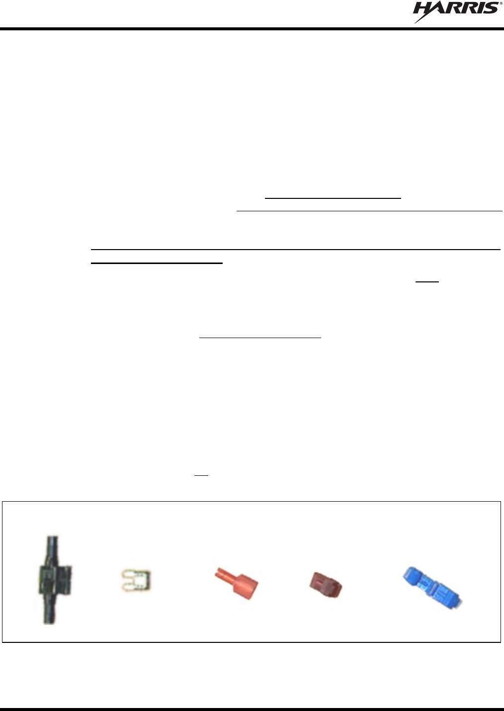
MM-018337-001
56
9. If not already, mount the switch to the vehicle’s dash panel, or other customer-selected location.
10. Obtain the 3-amp AGC fuse included with the cable, and install it into the fuse holder.
11. Tie and stow these wires as necessary so they remain out of the way of casual contact and wire chafe
is avoided.
12. Label this power switch accordingly. For example: “VRS7010 ON/OFF.”
10.4.2.3 Control Head and Radio Are “Hot Wired”
In the “hot-wired” configuration, the control head and VRMS7010 are turned on and off only by the
control head’s on/off/volume control located on the front panel of the control head. In this configuration,
the control head’s white wire must be connected to unswitched and fused 12-volt vehicle power. Follow
the procedure presented in Section 10.4.2.1, except connect the white wire to unswitched battery power
instead of switched (“Accessory”) power.
10.4.3 Using Vehicle Fuse and T-Tap Kit (Optional) Instead of Waterproof Inline
Fuse Holder (Standard)
The waterproof inline fuse holder and AGC fuse included with the DC Power Cable must be used if the
white wire connection point is located in a harsh environment such as in the vehicle’s engine
compartment. In this case, disregard all information presented in this section, and follow one of the three
procedures presented in Section 10.4.2 to connect the white wire.
However, if the connection point is not in a harsh environment, such as under the vehicle’s dash panel,
Vehicle Fuse and T-Tap Kit FS24473 may be ordered and used to make the white wire connection. As
shown in Figure 10-6, this kit includes an ATM fuse holder and fuse, T-tap crimp terminals for tapping
into an existing vehicle switched power wire, and a quick-disconnect terminal. The following installation
procedure is recommended for this optional kit:
1. Locate the switched ignition or “Accessory” power wire (typically at or near the vehicle’s fuse block
or in a vehicle wiring harness) that will be used for the switched ignition power source. It may be
necessary to consult the vehicle manufacturer’s wiring diagram.
2. Route the white wire of the control head’s DC Power Cable from the back of the head to an area near
the switched ignition power source. At the back of the head, be sure to maintain a cable service length
of at least six (6) inches and do not loop the cable.
3. Cut a short section (6 to 8 inches) off the end of the white wire and strip each end of this short wire.
ATM 2-Amp Quick- T-Tap T-Tap
Fuse Holder ATM Disconnect Terminal for Terminal for
Fuse Terminal #22-18 AWG #16-14 AWG
(Gray) (Male Tab) Wire (Red) Wire (Blue)
(Shown Closed)
(Shown Open)
Figure 10-6: Contents of Vehicle Fuse and T-Tap Kit FS24473
4. From the Vehicle Fuse and T-Tap Kit, locate the male-tab quick-disconnect terminal and crimp it to
one end the short wire.
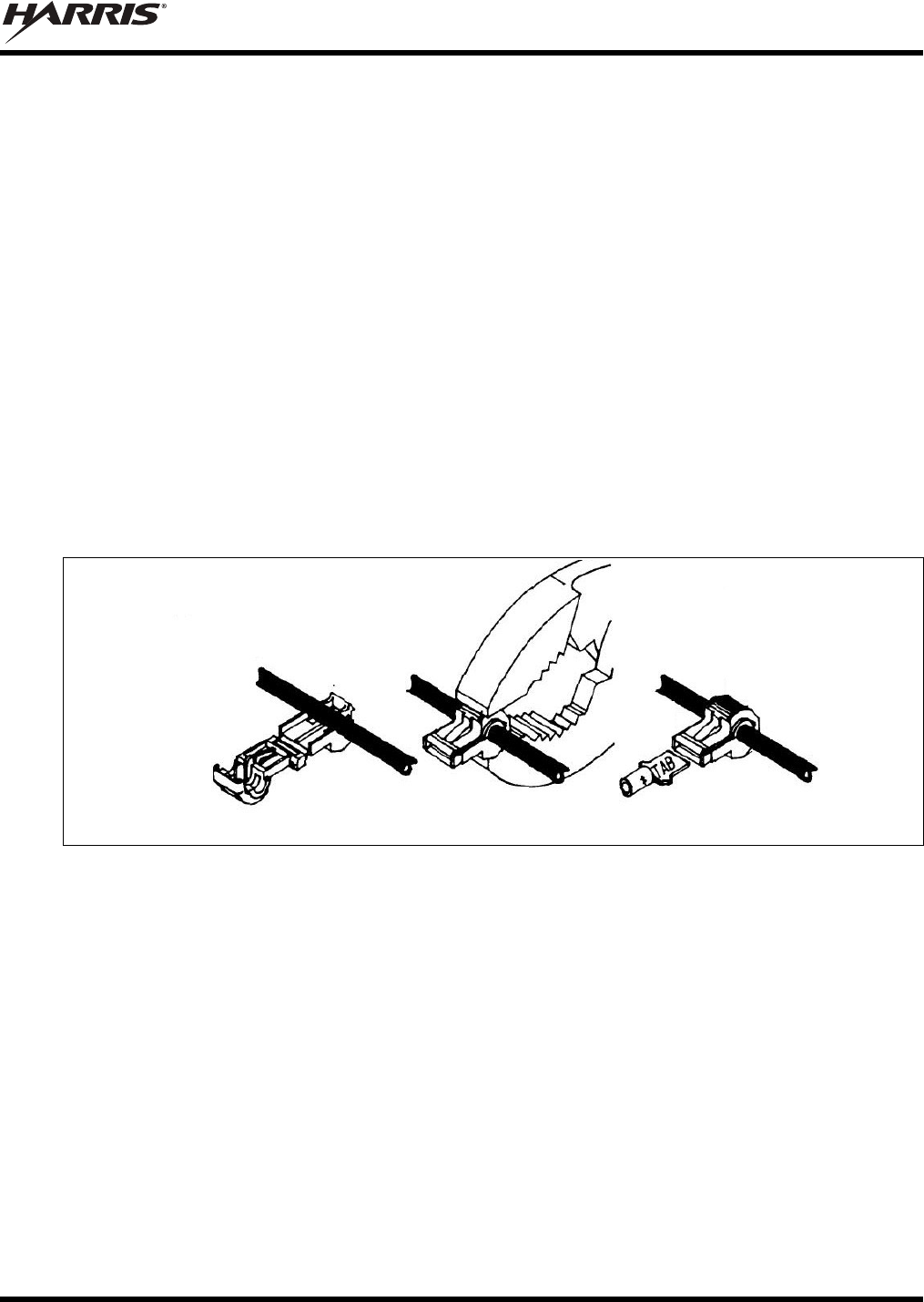
MM-018337-001
57
5. From the same kit, locate the ATM fuse holder and crimp it to the other end of the short wire. The
holder has built-in crimpable joints.
6. Cut the excess length from the white wire of the control head’s power cable, strip it, and crimp it to
the other side of the ATM fuse holder.
7. Pull enough of the switched ignition source wire out of the vehicle’s wiring harness so one of the
T-tap terminals may be attached to it.
8. Two T-tap terminals are included in the kit. Based on the gauge of wire, select the proper terminal
size: Red is for connecting to a 22 to 18-AWG wire, and blue is for connecting to an 18 to 14-AWG
wire.
9. Attach the selected T-tap terminal by fitting the wire into its wire groove and snapping the two halves
together with a pair of pliers as shown in Figure 10-7.
10. Push the male-tab quick-disconnect terminal into the T-tap terminal’s inlet until it is fully engaged.
11. Install the 2-amp ATM fuse into the fuse holder. It is recommended that a piece of electrical tape be
wrapped around the fuse connection to keep the fuse from being jostled out of the holder.
12. Tie and stow these wires as necessary so they remain out of the way of casual contact and wire chafe
is avoided.
Diagram Courtesy of 3M Corp.
Figure 10-7: Attaching T-Tap Terminals to a Switched Power Wire

MM-018337-001
58
11 SPEAKER INSTALLATION
Select a location for the speaker that will allow for proper listening range with a moderate volume setting.
Total speaker cable length (of both cables) is approximately five (5) feet. Therefore, to include service
loops in the cables, the speaker must be mounted within approximately 4.5 feet of the control head.
1. Install the speaker (Item 12 in Table 4-2) using the hardware and mounting bracket supplied with it.
Also refer to the instructions included in the speaker for additional mechanical installation
information.
2. Route the speaker’s cable to the rear of the control head.
3. Mate the Speaker Cable (Item 13 in Table 4-2) to the 2-pin connector at the rear of the control head
by visually aligning the ¾-moon-shaped keys of the connectors, and then pushing and turning the
outer locking ring of the cable connector clockwise until it stops. A mild click will be sensed to
confirm proper mating.
4. Connect the speaker’s 2-pin plastic connector to the respective mating connector on the Speaker
Cable.
5. Route the cables out of the way of casual contact, and tie and stow as necessary.
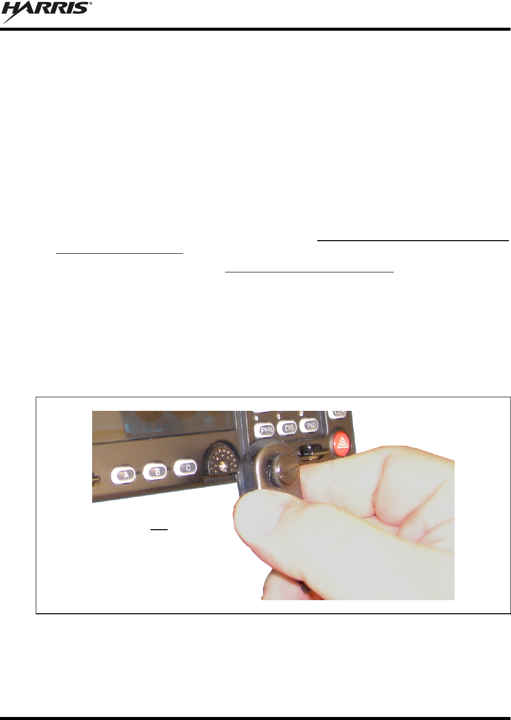
MM-018337-001
59
12 MICROPHONE ATTACHMENT
There are several versions of microphones available for use with the CH-721 control head. Each has a
17-pin flush-mount type connector that mates with the microphone (“mic”) connector on the front panel
of the control head. The mic’s connector includes a captive thumbscrew that secures it to the mic
connector on the front panel of the control head. A microphone clip is included with each microphone.
The radio can be configured to provide a monitor function when the microphone is cradled in the clip.
Connect the mic to the control head and install the clip as follows:
1. As illustrated in Figure 12-1, grasp the mic’s connector with a thumb and index finger on the sides of
the connector just adjacent to the thumbscrew.
2. Position connector just in front of the control head’s mic connector so its male pins can engage
straight into the female (socket) pins of the control head’s mic connector. The thumbscrew must be
oriented directly above the hanging mic cable.
3. Mate the two connectors by pressing them fully together. Do not apply any force to the thumbscrew
when mating the connectors.
4. Tighten the thumbscrew finger-tight. Do not use a screwdriver to tighten it.
5. Using the microphone clip as a template, drill mounting holes in the surface of the selected location.
6. Attach the microphone clip to the mounting surface using self-threading screws. Select a location that
has clearance for the mic when it is attached to the clip.
7. The microphone clip must be grounded to the vehicle’s chassis. If not mounted to a grounded metal
surface, complete this requirement by adding a jumper wire attached from chassis ground to the clip.
8. Clip the microphone to the clip.
Figure 12-1: Attaching the Microphone to the CH-721 Control Head
As illustrated, do not apply any
force to the thumbscrew when
mating the mic connectors.
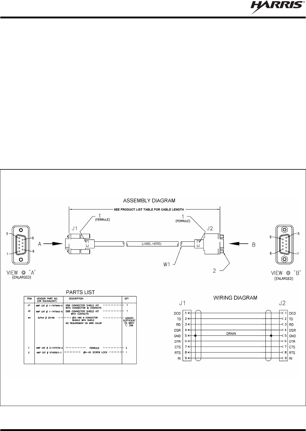
MM-018337-001
60
13 OPTIONAL CABLES
13.1 SERIAL PROGRAMMING CABLE CA-013671-020
Serial Programming Cable CA-013671-020 (20 feet long) can be used to program and configure the
VRMS7010 and VRBS7010 via a Personal Computer. This cable can also be used to extend the length of
GPS NMEA-formatted serial data connections. The cable’s assembly and wiring diagrams are shown in
Figure 13-1 below.
To program and configure the VRMS7010, the cable’s male DB-9 connector (J1) mates to the female
DB-9 serial port connector on the rear of the VRMS7010. To program and configure the VRBS7010, the
cable’s male DB-9 connector (J1) mates to the female DB-9 serial port connector of Interface Cable
CA-012349-003. Alternately, if the cable is being used to carry GPS NMEA-formatted serial data from
the VRMS7010, its male DB-9 connector mates to connector P5 of Interface Cable CA-012349-003.
The cable’s female DB-9 connector (J2) mates to a PC’s male DB-9 serial port connector. If the utilized
PC is not equipped with a DB-9 serial port connector, the use of a suitable adapter is required, such as
USB-to-RS-232 Adapter Cable CN24741-0001. As of the publication of this manual, CN24741-0001 is
available via the Customer Resource Center; refer to Section 3.6 on page 19 for contact information.
(Made From PS-CA-013671 Rev. -)
Figure 13-1: Serial Programming Cable CA-013671-020
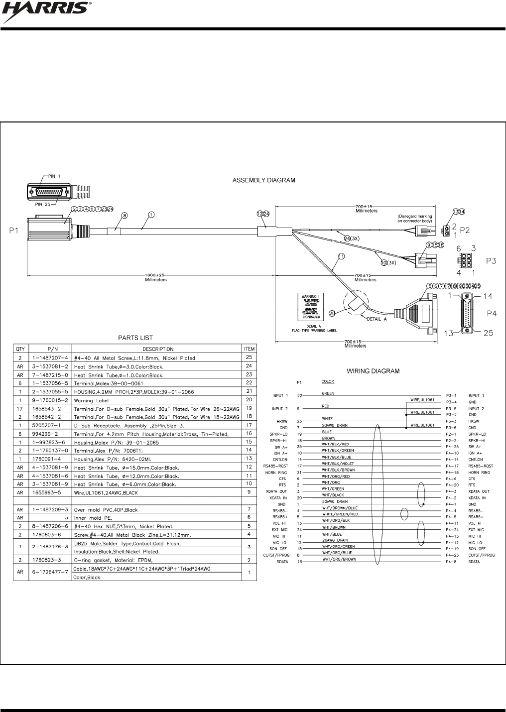
MM-018337-001
61
13.2 CH-721 OPTION CABLE CA-011854-001
CH-721 Option Cable CA-011854-001 can be used to connect optional equipment to the 25-pin
D-subminiature (DB-25) connector on the rear of the CH-721. This cable expands the connections
available at the 25-pin connector to three (3) separate connectors. The cable’s assembly and wiring
diagrams are shown in Figure 13-2 below.
(Made From PS-CA-011854 Rev. D)
Figure 13-2: CH-721 Option Cable CA-011854-001
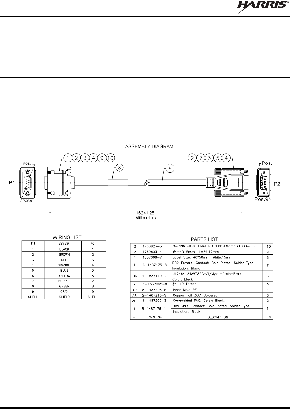
MM-018337-001
62
13.3 CH-721 SERIAL PROGRAMMING CABLE CA-104861
Serial Programming Cable CA-104861 (5 feet) can be used to program and configure the CH-721 control
head via a Personal Computer. This cable has a female DB-9 connector on one end for connection to the
PC’s serial port connector and a male DB-9 connector on the other end for connection to the serial port
connector on the rear of the head. The cable’s assembly diagram and wiring list are shown in Figure 13-3
below.
(Made From PS-CA-104861 Rev. A)
Figure 13-3: Programming Cable CA-104861
MM-018337-001
63
14 GPS NMEA-FORMATTED SERIAL DATA
CONNECTION
To obtain GPS NMEA-formatted serial data from the VRMS7010, follow this procedure to complete
serial data connections:
1. Connect the DB-9 female connector labeled “GPS” of Interface Cable to the computer’s serial port
DB-9 male connector—either directly or extended via a serial cable. Serial Programming Cable
CA-013671-020 (20 feet) can be used to extend the length; see Section 13.1 for additional
information. Tighten the screws firmly, and then route the cabling as required. If the computer is not
equipped with a DB-9 serial port connector, the use of a suitable adapter is required, such as
USB-to-RS-232 Adapter Cable CN24741-0001.
2. Follow the manufacturer’s instructions on processing the NMEA-formatted GPS data from the radio.
Industry software to process GPS information through this interface is not supported by
Harris.

MM-018337-001
64
15 INITIAL POWER-UP TEST
1. At the main inline fuse holders located near the vehicle battery (or DC power access point), insert a
15-amp AGC fuse into the fuse holder for VRMS7010 main power. The fuse was included with the
respective DC Power Cable (installed per Section 9.2.1.2).
2. Insert another 15-amp AGC fuse into the fuse holder for VRBS7010 main power. The fuse was
included with the respective DC Power Cable (installed per Section 9.2.1.2).
3. If not already, insert a 5-amp AGC fuse into the fuse holder for the CH-721 control head’s main
power fuse. The fuse was included with the respective DC Power Cable.
4. If not already, near the vehicle’s fuse panel, install a 3-amp AGC fuse in the respective inline fuse
holder. The fuse was included with the respective DC Power Cable. However, if Vehicle Fuse and
T-Tap Kit FS24473 was used to make the control head’s ignition/switched power connection, install
the 2-amp ATM fuse included with the T-tap kit.
5. Tie and stow all fuse holders and wiring to prevent excess vibration/movement.
6. Carefully reconnect the vehicle’s battery ground cable.
7. If not already, temporarily connect the two mobile antenna cables from the vehicle-mounted antennas
to the female TNC RF connector at the rear of the two radios. These are temporary connections until
test procedures in Section 16 are complete.
8. If the VRMS7010 is equipped with the GPS receiver option, permanently connect the antenna cable
from the GPS antenna (or mobile/GPS combo antenna) to the female SMA connector on the rear
panel of the radio. The male SMA connector on most GPS antenna cables has a 5/16-inch hex collar,
so the use of a wrench of this same size is normally required for tightening. However, some may have
collars with only knurled surfaces, so a standard wrench or torque wrench cannot be used. In either
case, do not over tighten the connector and do not twist the cable when tightening.
9. If the installation is wired so the vehicle’s ignition key/switch turns the radio on and off, turn the
switch to the Accessory or Run position.
10. If the control head is not already powered up, do so by rotating its on/off/volume control clockwise
out of the detent position.
11. Verify the control head has powered-up by observing its display. If the display is not lit, refer to
Section 9.1 as necessary.
As long as the software configuration parameters have been loaded, successful installation is almost
immediately realized:
After a short boot-up sequence, the control head displays login information and/or a talk group.
If no errors are displayed, the installation is most-likely properly wired.
If an error is displayed, recheck all cable connections, verify all fuses are properly installed, and
verify battery power is getting to the radios’ main power fuses. If problems persist, contact the
Technical Assistance Center (see page 19).
Consult the Operator’s Manual for operational information. Refer to Section 3.5 on page 19 as
necessary.
Refer to the following section for performance test information.
MM-018337-001
65
16 PERFORMANCE TESTS
This section includes procedures to verify the performance of the installation’s antennas. Procedures
include:
VRMS7010 and VRBS7010 Testing by Transmitting into a 50-Ohm RF Load/Terminator (“Dummy
Load”)
VRMS7010 and VRBS7010 Testing by Transmitting into the Respective Radio Antennas
CAUTION
The accuracy of test results depends upon a DC power source in the range of 13.6 volts
DC 10%, with a current capacity of greater than 15 amps. Make sure the vehicle’s
battery is fully charged by running the engine for a few minutes before the test, and
keep the engine running during the test procedures. Abide by the following
WARNING!
If the vehicle’s engine must remain running, the vehicle location should be well
ventilated so exhaust fumes from the engine do not cause harm!
CAUTION
If a vehicle equipped with a VRS7010 requires jump-starting, the radio installation’s
four (4) fuses should be removed from the fuse holders prior to jump-starting. Doing
so will prevent damage to the VRS7010 and CH-721.
Prior to installation, the VRS7010’s VRMS7010 and VRBS7010 transmit RF output
power levels should be configured appropriately. The wide range of power levels
indicated in the following procedures take into account such things as: customer’s
requirements; measurement errors, especially to include uncalibrated equipment;
cabling losses; and temperature variations. By no means should the result from
Performance Testing in this section be construed as the exact value of power level
outputs from the VRS7010, as values are set and more accurately measured in the
factory. The values obtained in these test procedures determine a successful installation
only.

MM-018337-001
66
16.1 REQUIRED TEST EQUIPMENT
Table 16-1: Test Equipment Required for Performance Tests
TEST EQUIPMENT MODEL / PART NUMBER & DESCRIPTION
Peak-Reading
Wattmeter Bird Electronic Corp. Model 4314B (or equivalent) with Type N female
connectors at input and output ports.
100-Watt
RF Wattmeter
Slug
Bird Electronic Corp. Element 100E, 100-watt, 400 - 1000 MHz (or
equivalent).
5-Watt
RF Wattmeter
Slug
Bird Electronic Corp. Element 5E, 5-watt, 400 - 1000 MHz (or
equivalent).
RF Coaxial
Jumper Cable
Pasternack Enterprises PE3661-36 (or equivalent) 50-Ohm Coaxial
Cable with TNC male connector and Type N male connector,
approximately three (3) feet in length. The utilized cable must have
VSWR below 1.5:1 within the RF passband.
Type N Male-to-TNC
Female RF Adapter
Pasternack Enterprises PE9090 or Amphenol Connex 242130 (or
equivalent) Type N male to TNC female adapter. Required to connect
the cable of the vehicle-mounted antennas to the wattmeter.
Type N Female-to-
TNC Male RF
Adapter
Pasternack Enterprises PE9089 or Amphenol Connex 242131 (or
equivalent) Type N female to TNC male adapter. Required to connect
a female TNC connector to a 50-ohm RF load/terminator.
Two (2)
50-Ohm RF
Loads/Terminators
(“Dummy Loads”)
Pasternack Enterprises PE6106 (or equivalent) 50-ohm RF terminator
rated at greater than 50 watts power, with Type N male connector.
Two 50-ohm RF terminators are required.
Vehicle-Mounted
Antennas Tests are performed with the vehicle-mounted antennas.
16.2 VRMS7010 TRANSMITTING INTO A 50-OHM LOAD/TERMINATOR
1. At the rear of the VRMS7010, disconnect the antenna cable from the 800 MHz bandpass filter’s
antenna connector (TNC connector labeled “OUTPUT”). If it is not already, label this cable as the
“VRMS7010 Antenna” cable. This should be the cable from the highest (vehicle rooftop-mounted)
antenna.
2. Using the Type N male to TNC male coaxial jumper cable, connect the antenna connector on the rear
of the 800 MHz bandpass filter (connector labeled “ANTENNA”) to the wattmeter’s input connector.
Refer to Figure 16-1 as necessary.
3. Connect a 50-ohm RF load/terminator to the wattmeter’s output connector.
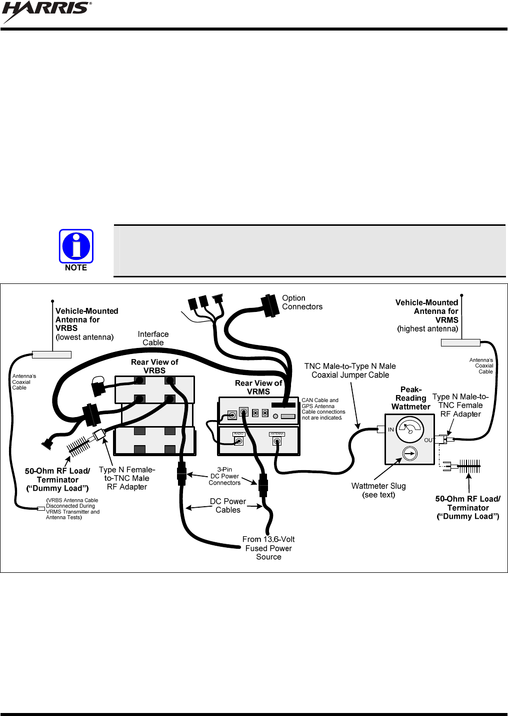
MM-018337-001
67
4. At the rear of the VRBS7010, disconnect the antenna cable from the VRBS7010. If it is not already,
label this cable from the antenna as the “VRBS7010 Antenna” cable. This should be the cable from
the lowest (vehicle trunk lid-mounted) antenna.
5. Connect the other 50-ohm RF load/terminator to the VRBS7010. Use the Type N female to TNC
male RF adapter. Refer to Figure 16-1 as necessary.
6. If not already, turn on the VRS7010 via the CH-721’s on/off volume control (or externally-mounted
switch). The front panel of the CH-721 is shown in Figure 10-1 on page 48. The VRS7010 powers-
up in the mobile-only mode (vehicular repeater disabled).
7. Set the VRS7010 (and thus the VRMS7010) to an 800 MHz test conventional channel.
8. Insert the 100-watt slug into the wattmeter and position the slug to measure forward RF output power.
Rotate it as necessary. The arrow on the face of the slug must point away from the VRMS7010 and
towards the 50-ohm load/terminator for forward power measurements.
It is recommended that a test conventional 800 MHz channel be allocated for this
testing. This same channel should be used during the antenna test procedure presented
in the next section.
Figure 16-1: Wattmeter Connections for VRMS7010 Antenna Tests
9. Set the wattmeter to measure peak RF power.
10. Key the VRMS7010 transmitter via the microphone’s PTT button.
11. For an 800 MHz band transmission, compare the wattmeter’s reading with the target RF output power
range of between 22.1 and 55.5 watts (35 watts ±2 dB). This transmit output power range assumes
the VRMS7010 is currently configured for high-power transmit. As stated in the NOTE on page 65,
this wide power level range takes into account errors caused by test cable loss, etc.
MM-018337-001
68
Transmit only for as long as needed to take the measurement, then immediately
disable the transmission.
12. If the wattmeter reading is within the range, record the measured value in the appropriate space on
the data collection form near the end of this manual (page 74).
If the wattmeter reading is outside the range, verify the VRS7010 power supply voltage (i.e.,
battery voltage) is within the specified range, recheck all connections and measure the RF output
power again. If this fails to produce a reading within the range, replace it and repeat this procedure. If
problems persist, contact the Technical Assistance Center (see page 19).
13. Un-key the transmitter by releasing the microphone’s PTT button.
16.3 VRMS7010 TRANSMITTING INTO ITS ANTENNA
1. To verify transmit output power of the VRMS7010, perform the test procedure presented in the
previous section (Section 16.2).
2. Disconnect the 50-ohm load/terminator from the wattmeter.
3. Connect the cable from the vehicle-mounted VRMS7010 antenna (cable labeled “VRMS7010
Antenna”) to the wattmeter’s output connector, as shown in Figure 16-1.
4. If not already, turn on the VRS7010 via the CH-721’s on/off volume control (or externally-mounted
switch). The front panel of the CH-721 is shown in Figure 10-1 on page 48. The VRS7010 powers-
up in the mobile-only mode (vehicular repeater disabled).
5. Set the VRS7010 (and thus the VRMS7010) to an 800 MHz test conventional channel. Use the same
channel that was used when performing the previous procedure.
It is recommended that a test conventional 800 MHz channel be allocated for this
testing. Otherwise, interference with other radio users in the system may occur. Also,
during transmissions, always observe the RF exposure-related safety information
presented in Section 1.2 of this manual (begins on page 6).
6. Insert the 100-watt slug into the wattmeter and position the slug to measure forward RF output power.
Rotate it as necessary. The arrow on the face of the slug must point away from the VRMS7010 and
towards the antenna for forward power measurements.
7. Set the wattmeter to measure peak RF power.
8. Key the transmitter via the microphone’s PTT button.
9. For an 800 MHz band transmission, compare the wattmeter’s reading with the target RF output power
range of between 22.1 and 55.5 watts (35 watts ±2 dB). This transmit output power range assumes
the VRMS7010 is currently configured for high-power transmit. As stated in the last NOTE on page
65, this wide power level range takes into account errors caused by test cable loss, etc.
Transmit only for as long as needed to take the measurement, then immediately
disable the transmission.
MM-018337-001
69
10. If the wattmeter reading is within the range, record the value in the appropriate space on the data
collection form near the end of this manual (page 74).
If the wattmeter reading is outside the range, verify the VRMS7010 power supply voltage (i.e.,
battery voltage) is within the specified range, recheck all connections, and measure the forward power
again. If this fails to produce a reading within the range, check all cabling and connections, and repeat
the testing procedure to this point. In the event the wattmeter reading still falls outside the range,
replace the antenna, make sure all connections are seated firmly, and repeat the testing procedure. If
problems persist, contact the Technical Assistance Center (see page 19).
11. Position the wattmeter’s 100-watt slug to measure reverse (reflected) RF power from the antenna. The
arrow on the face of the slug must point away from the antenna and towards the VRMS7010 to
measure reverse power.
12. Key the transmitter via the microphone’s PTT button.
13. Compare the wattmeter reading with the RF power output range of 2 watts or less.
Transmit only for as long as needed to take the measurement, then immediately disable
the transmission.
14. If the wattmeter reading is within the range, record the value in the appropriate space on the data
collection form near the end of this manual (page 74).
If the wattmeter reading is outside the range, make sure the antenna is consistent with the specified
frequency range of the VRMS7010. Recheck all antenna connections, and measure the reverse power
again. If this fails to produce a reading within the range, replace the antenna and repeat the entire
antenna test procedure. Any value exceeding the maximum allowable reflected power value will
result in a diminished RF output signal. If problems persist, contact the Technical Assistance Center
(see page 19).
15. Un-key the transmitter by releasing the microphone’s PTT button.
16. Disconnect the coaxial cable jumper and wattmeter.
17. Permanently connect the cable from the vehicle-mounted VRMS7010 antenna to the 800 MHz
bandpass filter’s antenna connector (labeled “ANTENNA”) by mating the two TNC connectors
together. Use a pair of soft-jaw pliers to gently tighten this connection. Do not over tighten and do not
twist the antenna cable.
18. Make several test calls on the radio system to verify VRMS7010 operation. Before making the calls,
select another conventional channel(s), as required to verify operation.
To prevent RF leakage and ensure peak performance, make sure the RF connectors are
tight, but do not over-tighten so connector damage will not occur.
Improper installation of the RF cables may lead not only to poor radio
performance but also to harmful exposure to RF electromagnetic energy.
MM-018337-001
70
16.4 VRBS7010 TRANSMITTING INTO A 50-OHM LOAD/TERMINATOR
1. If it is not already, disconnect the VRBS7010 antenna cable at the rear of the VRBS7010. Label this
cable from the antenna as the “VRBS7010 Antenna” cable. This should be the cable from the lowest
(vehicle trunk lid mounted) antenna.
2. Using the Type N male to TNC male coaxial jumper cable, connect the antenna connector at the rear
of the VRBS7010 to the wattmeter’s input connector. See Figure 16-2.
3. Connect a 50-ohm RF load/terminator to the wattmeter’s output connector.
4. Insert a 5-watt slug into the wattmeter and position the slug to measure forward RF output power.
Rotate it as necessary. The arrow on the face of the slug must point away from the VRBS7010 and
towards the 50-ohm load/terminator for forward power measurements.
5. Set the wattmeter to measure peak RF power.
6. If not already, turn on the VRS7010 via the CH-721’s on/off volume control (or externally-mounted
switch). The front panel of the CH-721 is shown in Figure 10-1 on page 48. The VRS7010 powers-
up in the mobile-only mode (vehicular repeater disabled). Refer to the operator’s manual as
necessary.
7. Switch the VRS7010 to a P25 trunked radio network (i.e., make a “system” change if necessary).
8. Enable/Activate the extended coverage (XCOV) vehicular repeater mode as follows:
a. Press the control head’s MENU button.
b. Use the control head’s / Ramp Control to scroll through the menu until “P25 Menu”
appears in the middle line of the display.
c. Press the MENU button again. After a short delay, “VR Standby” will appear in the display,
indicating the VRS7010 is operating in XCOV vehicular repeater mode and waiting for (client)
radios to connect to it. When one or more radios connect, the display changes to “VR Active.”
Within twelve (12) seconds of enabling the XCOV vehicular repeater mode, the
VRBS7010 should begin transmitting control channel information on a 700 MHz RF
channel.
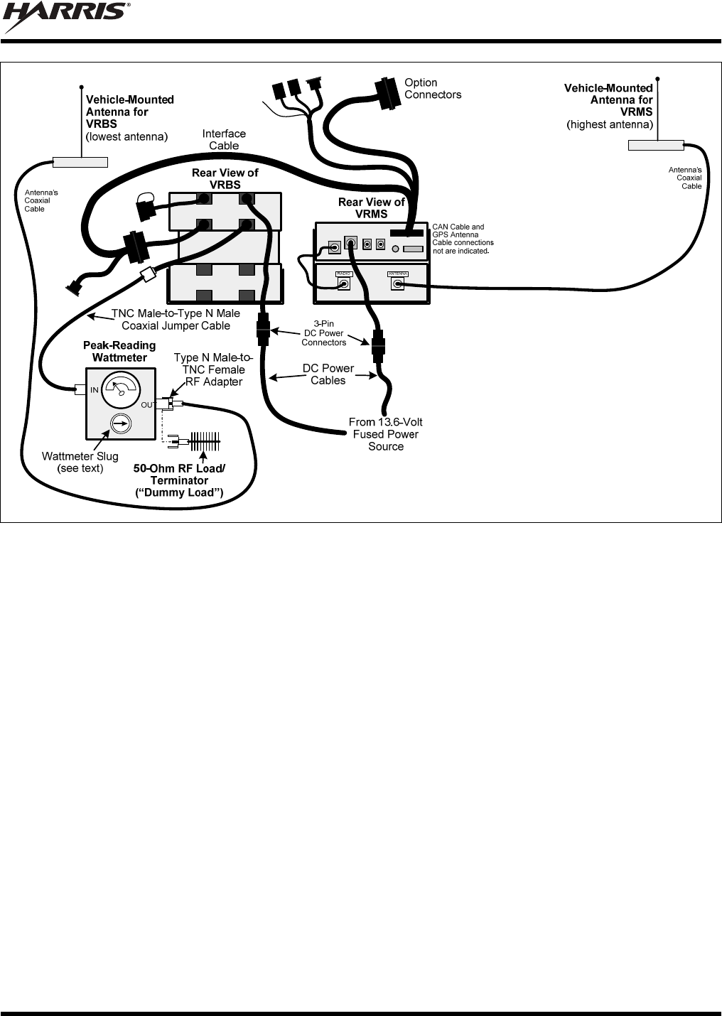
MM-018337-001
71
Figure 16-2: Wattmeter Connections for VRBS7010 Antenna Tests
9. For the 700 MHz band transmission, compare the wattmeter’s reading with the target RF output
power range of between 2.4 and 3.8 watts (3 watts ±1 dB). This transmit output power range
assumes the VRBS7010 is currently configured for high-power transmit.
10. If the wattmeter reading is within the range, record the measured value in the appropriate space on
the data collection form near the end of this manual (page 74).
If the wattmeter reading is outside the range, verify the VRS7010’s power supply voltage (i.e.,
battery voltage) is within the specified range, recheck all connections and measure the RF output
power again. If this fails to produce a reading within the range, replace it and repeat this procedure. If
problems persist, contact the Technical Assistance Center (see page 19).
11. At the control head, disable P25 vehicular repeater mode. The VRBS7010 should immediately stop
transmitting, as indicated by the wattmeter.
16.5 VRBS7010 TRANSMITTING INTO ITS ANTENNA
1. To verify transmit output power of the VRBS7010, perform the test procedure presented in the
previous section (Section 16.4).
2. Disconnect the 50-ohm load/terminator from the wattmeter.
3. Connect the cable from the vehicle-mounted VRBS7010 antenna (cable labeled “VRBS7010
Antenna”) to the wattmeter’s output connector. See Figure 16-2.
MM-018337-001
72
4. Insert a 5-watt slug into the wattmeter and position the slug to measure forward RF output power.
Rotate it as necessary. The arrow on the face of the slug must point away from the VRBS7010 and
towards the 50-ohm load/terminator for forward power measurements.
5. Set the wattmeter to measure peak RF power.
6. If not already, turn on the VRS7010 via the CH-721’s on/off volume control (or externally-mounted
switch). The front panel of the CH-721 is shown in Figure 10-1 on page 48. The VRS7010 powers-
up in the mobile-only mode (vehicular repeater disabled).
7. Enable the extended coverage (XCOV) P25 vehicular repeater mode. Refer to step 8 in the previous
section (Section 16.4) as necessary. If no radios are connected to the VRS7010, “VR Standby” is
indicated in the control head’s display. When one or more radios connect, the display changes to
“VR Active.”
Within twelve (12) seconds of enabling the XCOV vehicular repeater mode, the
VRBS7010 should begin transmitting control channel information on a 700 MHz RF
channel.
Since the VRS7010’s VRBS7010 automatically begins transmitting soon after
enabling the vehicular repeater mode, before enabling this mode, an antenna
must be connected to the VRBS7010 and VRMS7010 antennas and personnel
should be at least the minimum safe distance from these two (2) antennas.
Minimum safe distances from the VRMS7010 antenna are listed in Table 1-1 (on
page 8). Minimum safe distances from the VRBS7010 antenna are listed in Table
1-2 (on page 9).
8. For the 700 MHz band transmission, compare the wattmeter’s reading with the target RF output
power range of between 2.4 and 3.8 watts (3 watts ±1 dB). This transmit output power range
assumes the VRBS7010 is currently configured for high-power transmit.
9. If the wattmeter reading is within the range, record the value in the appropriate space on the data
collection form near the end of this manual (page 74).
If the wattmeter reading is outside the range, first verify the VRBS7010 antenna’s driven element
is properly trimmed. Before making any antenna adjustments, be sure to disable P25 vehicular
repeater mode so the VRBS7010 will stop transmitting. Next, verify VRBS7010 power supply
voltage (i.e., battery voltage) is within the specified range, recheck all connections, and measure the
forward power again. If this fails to produce a reading within the range, check all cabling and
connections, and repeat the testing procedure to this point. In the event the wattmeter reading still
falls outside the range, replace the antenna, make sure all connections are seated firmly, and repeat
the testing procedure. If problems persist, contact the Technical Assistance Center (see page 19).
10. At the CH-721, disable the P25 vehicular repeater mode. The VRBS7010 should immediately stop
transmitting, as indicated by the wattmeter.
11. Position the wattmeter’s 5-watt slug to measure reverse (reflected) RF power from the antenna. The
arrow on the face of the slug must point away from the antenna and towards the VRBS7010 to
measure reverse power.
12. At the CH-721, enable P25 vehicular repeater mode. Within twelve (12) seconds, the VRBS7010
should begin transmitting control channel information on a 700 MHz RF channel.
13. Compare the wattmeter reading with the RF power output range of less than ½ watt.
MM-018337-001
73
14. If the wattmeter reading is within the range, record the value in the appropriate space on the data
collection form near the end of this manual (page 74).
If the wattmeter reading is outside the range, first verify the VRBS7010 antenna’s driven element
is properly trimmed. Before making any antenna adjustments, be sure to disable P25 vehicular
repeater mode so the VRBS7010 will stop transmitting. Verify VRBS7010 power supply voltage
(i.e., battery voltage) is within the specified range, recheck all connections, and measure the forward
power again. If this fails to produce a reading within the range, check all cabling and connections, and
repeat the testing procedure to this point. In the event the wattmeter reading still falls outside the
range, replace the antenna, make sure all connections are seated firmly, and repeat the testing
procedure. If problems persist, contact the Technical Assistance Center (see page 19).
15. At the CH-721, disable P25 vehicular repeater mode. The VRBS7010 should immediately stop
transmitting, as indicated by the wattmeter.
16. Disconnect the coaxial cable jumper and wattmeter.
17. Permanently connect the cable from the vehicle-mounted VRBS7010 antenna to the VRBS7010
antenna connector at the rear of the VRBS7010. Mate the two TNC connectors together. Use two
pairs of soft-jaw pliers to gently tighten this connection. Do not over tighten and do not twist the
cable.
18. Re-enable extended coverage (XCOV) P25 vehicular repeater mode and make several test calls
between P25 radios connected to the VRS7010.
To prevent RF leakage and ensure peak performance, make sure the RF connectors are
tight, but do not over-tighten so connector damage will not occur.
Improper installation of the RF cables may lead not only to poor radio
performance but also to harmful exposure to RF electromagnetic energy.
MM-018337-001
74
16.6 TEST PERFORMANCE DATA FORM
Enter the information requested on this data collection form. Clip this form and file it as a permanent record of
the tested performance of the installed VRS7010.
Clip
Here
Company Performing Installation Technician Performing Test
Date of Test
(mm/dd/yyyy)
VRMS7010
Serial Number VRBS7010 Antenna
Make and Model Number
VRBS7010 Power Into
50-Ohm Load
Watts
VRBS7010 Forward
Power with Antenna VRBS7010 Reflected
Power with Antenna
Watts
Watts
VRMS7010 Power Into
50-Ohm Load
Watts
VRMS7010 Forward
Power with Antenna VRMS7010 Reflected
Power with Antenna
Watts
Watts
VRB
Serial Number VRMS7010 Antenna
Make and Model Number

MM-018337-001
75
17 COMPLETE THE INSTALLATION
Double-check the following items before considering the installation completed:
Verify all newly installed mechanical hardware is mounted securely and all respective mounting
hardware is tight.
Verify all electrical interconnections are connected properly and the associated connector attachment
hardware is tight. Pay special attention to all RF antenna cables!
Verify all related fuses are correctly installed, properly rated, and correctly labeled.
Verify all electrical cables and wiring are tied, stowed, and protected so they are out of the way of
casual contact, away from sources of extreme heat, and wire chafing cannot occur. Pay special
attention to all RF antenna cables!
To prevent fumes from entering the vehicle’s passenger compartment, seal the hole/grommet/wire
combination at the firewall with a silicon-based sealer.
Verify all vehicle components are properly reinstalled such as kick panels, headliners, and seats.
If the installation includes a separately-mounted on/off power switch for manually turning the V-TAC
mobile radio (and possibly others systems) on and off, verify it is labelled accordingly. For example:
“Radio ON/OFF.”
Remove all tools and unused hardware from the vehicle.
Verify the test performance data has been recorded on the data collection form shown in this manual.
Consult with the radio system administration personnel and placard/post required minimum antenna
separation distances in plain view of all VRS7010 user/operator positions.

MM-018337-001
76
18 WARRANTY
A. Harris Corporation, a Delaware Corporation, through its RF Communications Division (hereinafter
"Seller") warrants to the original purchaser for use (hereinafter "Buyer") that Equipment manufactured
by or for the Seller shall be free from defects in material and workmanship, and shall conform to its
published specifications. With respect to all non-Seller Equipment, Seller gives no warranty, and only
the warranty, if any, given by the manufacturer shall apply. Rechargeable batteries are excluded
from this warranty but are warranted under a separate Rechargeable Battery Warranty (ECR-7048).
B. Seller’s obligations set forth in Paragraph C below shall apply only to failures to meet the above
warranties occurring within the following periods of time from date of sale to the Buyer and are
conditioned on Buyer’s giving written notice to Seller within thirty (30) days of such occurrence:
1. for fuses and non-rechargeable batteries, operable on arrival only.
2. for parts and accessories (except as noted in B.1) sold by Seller’s Service Parts Operation, ninety
(90) days.
3. for P7300, P7200, P7100IP, P5400, P5300, P5200, P5100, P3300, M7300, M7200 (including V-
TAC), M7100IP, M5300 and M3300 radios, two (2) years, effective 10/01/2007.
4. for Unity™ XG-100P, three (3) years.
5. for all other equipment of Seller’s manufacture, one (1) year.
C. If any Equipment fails to meet the foregoing warranties, Seller shall correct the failure at its option (i)
by repairing any defective or damaged part or parts thereof, (ii) by making available at Seller’s factory
any necessary repaired or replacement parts, or (iii) by replacing the failed Equipment with equivalent
new or refurbished Equipment. Any repaired or replacement part furnished hereunder shall be
warranted for the remainder of the warranty period of the Equipment in which it is installed. Where
such failure cannot be corrected by Seller’s reasonable efforts, the parties will negotiate an equitable
adjustment in price. Labor to perform warranty service will be provided at no charge during the
warranty period only for the Equipment covered under Paragraph B.3 and B.4. To be eligible for no-
charge labor, service must be performed at Seller’s factory, by an Authorized Service Center (ASC)
or other Servicer approved for these purposes either at its place of business during normal business
hours, for mobile or personal equipment, or at the Buyer’s location, for fixed location equipment.
Service on fixed location equipment more than thirty (30) miles from the Service Center or other
approved Servicer’s place of business will include a charge for transportation.
D. Seller’s obligations under Paragraph C shall not apply to any Equipment, or part thereof, which (i) has
been modified or otherwise altered other than pursuant to Seller’s written instructions or written
approval or, (ii) is normally consumed in operation or, (iii) has a normal life inherently shorter than the
warranty periods specified in Paragraph B, or (iv) is not properly stored, installed, used, maintained or
repaired, or, (v) has been subjected to any other kind of misuse or detrimental exposure, or has been
involved in an accident.
E. The preceding paragraphs set forth the exclusive remedies for claims based upon defects in or
nonconformity of the Equipment, whether the claim is in contract, warranty, tort (including
negligence), strict liability or otherwise, and however instituted. Upon the expiration of the warranty
period, all such liability shall terminate. The foregoing warranties are exclusive and in lieu of all other
warranties, whether oral, written, expressed, implied or statutory. NO IMPLIED OR STATUTORY
WARRANTIES OF MERCHANTABILITY OR FITNESS FOR PARTICULAR PURPOSE SHALL
APPLY. IN NO EVENT SHALL THE SELLER BE LIABLE FOR ANY INCIDENTAL,
CONSEQUENTIAL, SPECIAL, INDIRECT OR EXEMPLARY DAMAGES.
This warranty applies only within the United States.
Harris Corporation Harris Corporation
RF Communications Division RF Communications Division
221 Jefferson Ridge Parkway 1680 University Avenue
Lynchburg, VA 24501 Rochester, NY 14610
1-800-528-7711 1-585-244-5830
ECR-7047J
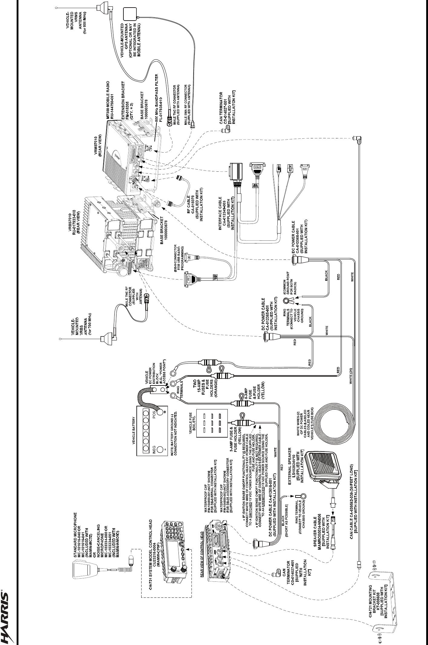
MM-018337-001
77
RED RED
RED
WHITE
RED
RED
19 WIRING DIAGRAM FOR VRS7010 AND CH-721
VRS7010 AND CH-721
WIRING DIAGRAM

Public Safety and Professional Communications | www.pspc.harris.com
221 Jefferson Ridge Parkway | Lynchburg, VA USA 24501 | 1-800-528-7711
Wiring Diagram Inside