HARRIS TR-0058-E Vehicular Repeater Base System (VRBS) User Manual 1
HARRIS CORPORATION Vehicular Repeater Base System (VRBS) 1
HARRIS >
Contents
- 1. Manual 1 rev
- 2. Manual 2 rev
- 3. User Manual 1
- 4. User Manual 2
User Manual 1
Operator’s Manual
MM-018336-001
Rev. B, Sep/11
VRS7000 Series
P25 Trunked Cross-Band
Vehicular Repeater Systems
VRS7010, VRS7020, and VRS7030
Includes VRBS7010, VRBS7020, VRBS7030,
VRMS7010, VRMS7020, and VRMS7030
MM-018336-001, Rev. B
2
MANUAL REVISION HISTORY
REV. DATE REASON FOR CHANGE
– June/10 Original release.
A April/11 Revised antenna part numbers, introduction, operation, and warranty sections.
B Sep/11 Added VRS7020 and VRS7030. Revised mobile radio operation section.
Harris Corporation, Public Safety and Professional Communications (PSPC) Business, continually evaluates its technical
publications for completeness, technical accuracy, and organization. You can assist in this process by submitting your
comments and suggestions to the following:
Harris Corporation fax your comments to: 1-434-455-6851
PSPC Business or
Technical Publications e-mail us at: PSPC_TechPubs@harris.com
221 Jefferson Ridge Parkway
Lynchburg, VA 24501 ACKNOWLEDGEMENT
This device is made under license under one or more of the following US patents: 4,590,473; 4,636,791; 5,148,482;
5,185,796; 5,271,017; 5,377,229; 4,716,407; 4,972,460; 5,502,767; 5,146,497; 5,164,986; 5,185,795; 5,226,084; 5,247,579;
5,491,772; 5,517,511; 5,630,011; 5,649,050; 5,701,390; 5,715,365; 5,754,974; 5,826,222; 5,870,405; 6,161,089; and
6,199,037 B1. DVSI claims certain rights, including patent rights under aforementioned U.S. patents, and under other U.S.
and foreign patents and patents pending. Any use of this software or technology requires a separate written license from
DVSI. CREDITS
Harris and assuredcommunications are registered trademarks of Harris Corporation.
All other brand and product names are trademarks, registered trademarks, or service marks of their respective holders.
NOTICE!
The material contained herein is subject to U.S. export approval. No export or re-export is permitted without written
approval from the U.S. Government. Rated: EAR99 in accordance with U.S. Dept. of Commerce regulations 15CFR774,
Export Administration Regulations.
Information and descriptions contained herein are the property of Harris Corporation. Such information and descriptions may
not be copied or reproduced by any means, or disseminated or distributed without the express prior written permission of
Harris Corporation, PSPC Business, 221 Jefferson Ridge Parkway, Lynchburg, VA 24501.
Repairs to this equipment should be made only by an authorized service technician or facility designated by the supplier. Any
repairs, alterations or substitutions of recommended parts made by the user to this equipment not approved by the
manufacturer could void the user's authority to operate the equipment in addition to the manufacturer's warranty.
This product conforms to the European Union WEEE Directive 2002/96/EC. Do not dispose of this product in a
public landfill. Take it to a recycling center at the end of its life.
This manual is published by Harris Corporation
without any warranty. Improvements and changes to this manual
necessitated by typographical errors, inaccuracies of current
information, or improvements to programs and/or equipment,
may be made by Harris Corporation
at any time and without notice. Such changes will be incorporated into new editions of
this manual. No part of this manual may be reproduced or transmitted in any
form or by any means, electronic or mechanical,
including photocopying and recording, for any purpose, without the express written permission of Harris Corporation.
Copyright © 2010, 2011, Harris Corporation.

MM-018336-001, Rev. B
3
TABLE OF CONTENTS
Section Page
1 REGULATORY AND SAFETY INFORMATION ................................................................................... 6
1.1 SAFETY SYMBOL CONVENTIONS ................................................................................................. 6
1.2 RF ENERGY EXPOSURE AWARENESS AND CONTROL INFORMATION FOR FCC
OCCUPATIONAL USE REQUIREMENTS ........................................................................................ 6
1.2.1 Federal Communications Commission Regulations ............................................................... 7
1.3 COMPLIANCE WITH RF EXPOSURE STANDARDS ...................................................................... 7
1.3.1 Mobile Antennas .................................................................................................................. 10
1.3.2 Approved Accessories .......................................................................................................... 11
1.3.3 Contact Information .............................................................................................................. 11
1.4 RADIO FREQUENCY INTERFERENCE ......................................................................................... 11
1.4.1 FCC Part 15 .......................................................................................................................... 11
1.4.2 Industry Canada .................................................................................................................... 11
1.5 OCCUPATIONAL SAFETY GUIDELINES AND SAFETY TRAINING INFORMATION ........... 11
1.6 COMMON HAZARDS ...................................................................................................................... 12
1.7 SAFE DRIVING RECOMMENDATIONS ........................................................................................ 13
1.8 OPERATING RULES REGULATIONS ............................................................................................ 13
1.9 OPERATING TIPS ............................................................................................................................. 14
2 INTRODUCTION ....................................................................................................................................... 15
2.1 VRS7000 SERIES OF P25 VEHICULAR REPEATERS ................................................................... 15
2.1.1 Primary Operating Modes .................................................................................................... 16
2.2 MULTIPLE ON-SCENE VEHICULAR REPEATERS ..................................................................... 17
2.3 LIMITATIONS OF THE VEHICULAR REPEATER ........................................................................ 18
2.3.1 General Information ............................................................................................................. 18
2.3.2 Limited Feature Set .............................................................................................................. 18
2.3.3 XCOV Vehicular Repeater Mode Disables Mobile Radio Mode ......................................... 18
2.3.4 Loss of Network Connectivity Disconnects Client Radios ................................................... 18
2.3.5 One Talk Path ....................................................................................................................... 19
2.3.6 Slight Audio Delay Between Client Radios and Network .................................................... 19
2.3.7 Other Limitations .................................................................................................................. 19
2.4 CH-721 SYSTEM MODEL CONTROL HEAD ................................................................................. 20
3 VEHICULAR REPEATER OPERATION ............................................................................................... 22
3.1 TURNING ON THE VRS7000 ........................................................................................................... 22
3.2 EXTENDED COVERAGE (XCOV) VEHICULAR REPEATER MODE ......................................... 22
3.2.1 Switch to a P25 Trunked Radio System (if not currently selected) ...................................... 22
3.2.2 Enable/Disable XCOV Vehicular Repeater Mode via the Control Head’s Menu ................ 23
3.2.3 Enable/Disable XCOV Vehicular Repeater Mode via Control Head Button (If
Programmed) ................................................................................................................. 23
3.2.4 Enable/Disable XCOV Vehicular Repeater Mode via External Switch ............................... 24
3.2.5 Indications During XCOV Vehicular Repeater Mode Operations ....................................... 24
4 MOBILE RADIO OPERATION ............................................................................................................... 26
4.1 FRONT PANEL OF THE CONTROL HEAD .................................................................................... 26
4.2 ADJUSTING DISPLAY AND BUTTON/KEY BACKLIGHT BRIGHTNESS ................................ 28
4.3 LOCKING AND UNLOCKING THE KEYPAD ............................................................................... 28
4.4 SELECTION MODE RULES ............................................................................................................. 29
4.5 DIRECT ACCESS .............................................................................................................................. 30
4.6 FEATURE ENCRYPTION DISPLAY ............................................................................................... 30
4.6.1 ROM Serial Number (12 Hex Digits) ................................................................................... 30
4.6.2 Feature Encryption Data Stream ........................................................................................... 31
4.6.3 Features Enabled .................................................................................................................. 31
4.7 SYSTEM/GROUP SELECTION ........................................................................................................ 32
4.7.1 System Selection .................................................................................................................. 32

MM-018336-001, Rev. B
4
TABLE OF CONTENTS
Section Page
4.7.2 Group Selection .................................................................................................................... 32
4.8 LAST SYSTEM/GROUP RECALL ................................................................................................... 33
4.9 DIGITAL VOICE OPERATION ........................................................................................................ 33
4.9.1 Receiving an Encrypted Call ................................................................................................ 33
4.9.2 Transmitting an Encrypted Call ............................................................................................ 33
4.10 MACRO KEY OPERATION .............................................................................................................. 34
4.11 RADIO STATUS ICONS ................................................................................................................... 34
4.12 MESSAGES ........................................................................................................................................ 35
4.13 ALERT TONES .................................................................................................................................. 38
4.14 MENU ................................................................................................................................................. 38
4.15 RECEIVING A CALL ........................................................................................................................ 42
4.16 SENDING A CALL ............................................................................................................................ 42
4.17 EMERGENCY OPERATION ............................................................................................................. 43
4.17.1 Receive an Emergency Call .................................................................................................. 43
4.17.2 Declare an Emergency .......................................................................................................... 43
4.18 SYSTEM SCAN OPERATION .......................................................................................................... 43
4.18.1 Wide Area System Scan ....................................................................................................... 43
4.18.2 ProScan™ ............................................................................................................................. 44
4.18.3 Priority System Scan ............................................................................................................. 44
4.18.4 When Wide Area System Scan Is Enabled ........................................................................... 44
4.18.5 When ProScan Is Enabled ..................................................................................................... 44
4.18.6 Menu Selection ..................................................................................................................... 44
4.18.7 Pre-Programmed Keypad Key .............................................................................................. 44
4.19 GROUP SCAN OPERATION ............................................................................................................ 45
4.19.1 Add Groups to a Scan List .................................................................................................... 45
4.19.2 Delete Groups from a Scan List ............................................................................................ 45
4.19.3 Nuisance Delete .................................................................................................................... 46
4.19.4 Turn Scan On ........................................................................................................................ 46
4.19.5 Priority Group Scanning ....................................................................................................... 46
4.19.6 Turn Scan Off ....................................................................................................................... 46
4.20 INDIVIDUAL CALLS ........................................................................................................................ 47
4.20.1 Receive and Respond to an Individual Call .......................................................................... 47
4.20.2 Call Storage Lists .................................................................................................................. 47
4.20.3 Send an Individual Call ......................................................................................................... 48
4.21 TELEPHONE INTERCONNECT CALLS ......................................................................................... 48
4.21.1 Receive a Telephone Interconnect Call ................................................................................ 48
4.21.2 Send a Telephone Interconnect Call ..................................................................................... 48
4.21.3 DTMF Overdial/Conventional Mode Telephone Interconnect ............................................. 49
4.21.4 Programmable Entries ........................................................................................................... 50
4.22 STATUS OPERATION ...................................................................................................................... 50
4.23 MESSAGE OPERATION ................................................................................................................... 50
4.24 PAGE .................................................................................................................................................. 51
5 TECHNICAL ASSISTANCE ..................................................................................................................... 51
6 KEYPAD REMAPPING ............................................................................................................................. 52
7 RADIO SETUP ............................................................................................................................................ 53
8 WARRANTY REGISTRATION ............................................................................................................... 56

MM-018336-001, Rev. B
5
LIST OF FIGURES
Page
Figure 2-1: Simplified Block Diagram of Extended Coverage (XCOV) Vehicular Repeater
Mode ..................................................................................................................................... 15
Figure 3-1: Control Head Indications during Vehicular Repeater Initialization .................................... 24
Figure 3-2: Control Head Indications with P25 Client Radio(s) Connected and a Call from
a P25 Client Radio or from the Radio Network .................................................................... 25
Figure 3-3: Control Head Indications with P25 Client Radio(s) Connected and an
Emergency Call on a Vehicular Repeater Talk Group .......................................................... 25
Figure 4-1: CH-721 System Model Control Head .................................................................................. 26
Figure 4-2: Typical Display during P25 Trunked Operation .................................................................. 34
LIST OF TABLES
Page
Table 1-1: Recommended Minimum Safe Lateral Distance from Transmitting Antenna for
Mobile Radio-to-Network Radio Link (VRMS7010/VRMS7020
Transmit/Receive Antenna) ..................................................................................................... 8
Table 1-2: Recommended Minimum Safe Lateral Distance from Transmitting Antenna for
Mobile Radio-to-Network Radio Link (VRMS7030 Transmit/Receive Antenna) ............... 10
Table 1-3: Recommended Minimum Safe Lateral Distance from Transmitting Antenna for
Vehicular Repeater-to-Portable Radio Link
(VRBS7010/VRBS7020/VRBS7030 Transmit/Receive Antenna) ....................................... 10
Table 4-1: Controls of CH-721 System Model Control Head ................................................................ 26
Table 4-2: Feature Numbers (Standard and Optional) ........................................................................... 32
Table 4-3: Radio Status Icons ................................................................................................................. 34
Table 4-4: Displayed Messages .............................................................................................................. 35
Table 4-5: Alert Tones for P25 Trunked Operation ............................................................................... 38
Table 4-6: Menu Item Information ......................................................................................................... 39
MM-018336-001, Rev. B
6
1 REGULATORY AND SAFETY INFORMATION
1.1 SAFETY SYMBOL CONVENTIONS
The following conventions are used in this manual to alert the user to general safety precautions that must
be observed during all phases of operation, service, and repair of this product. Failure to comply with
these precautions or with specific warnings elsewhere violates safety standards of design, manufacture,
and intended use of the product. Harris assumes no liability for the customer's failure to comply with
these standards.
WARNING
The WARNING symbol calls attention to a procedure, practice, or the like, which,
if not correctly performed or adhered to, could result in personal injury. Do not
proceed beyond a WARNING symbol until the conditions identified are fully
understood or met.
CAUTION
The CAUTION symbol calls attention to an operating procedure, practice, or the like,
which, if not performed correctly or adhered to, could result in damage to the
equipment or severely degrade equipment performance.
NOTE
The NOTE symbol calls attention to supplemental information, which may improve
system performance or clarify a process or procedure.
1.2 RF ENERGY EXPOSURE AWARENESS AND CONTROL
INFORMATION FOR FCC OCCUPATIONAL USE REQUIREMENTS
Before using the mobile two-way radio, read this important radio frequency (RF) energy awareness
and control information to ensure compliance with RF exposure guidelines.
WARNING
This radio is intended for use in occupational/controlled conditions, where users
have full knowledge of their exposure and can exercise control over their exposure
to remain below RF exposure limits. This radio is NOT authorized for general
population, consumer, or any other use.
CAUTION
Changes or modifications not expressly approved by Harris
could void the user's
authority to operate the equipment.
This two-way radio uses electromagnetic energy in the radio frequency (RF) spectrum to provide
communications between two or more users over a distance. It uses RF energy or radio waves to send and
receive calls. RF energy is one form of electromagnetic energy. Other forms include, but are not limited
to, electric power, sunlight, and x-rays. RF energy, however, should not be confused with these other
forms of electromagnetic energy, which, when used improperly, can cause biological damage. Very high
levels of x-rays, for example, can damage tissues and genetic material.
Experts in science, engineering, medicine, health, and industry work with organizations to develop
standards for exposure to RF energy. These standards provide recommended levels of RF exposure for
both workers and the general public. These recommended RF exposure levels include substantial margins
of protection. All two-way radios marketed in North America are designed, manufactured, and tested to
MM-018336-001, Rev. B
7
ensure they meet government-established RF exposure levels. In addition, manufacturers also recommend
specific operating instructions to users of two-way radios. These instructions are important because they
inform users about RF energy exposure and provide simple procedures on how to control it. Please refer
to the following websites for more information on what RF energy exposure is and how to control
exposure to assure compliance with established RF exposure limits:
http://www.fcc.gov/oet/rfsafety/rf-faqs.html
http://www.osha.gov./SLTC/radiofrequencyradiation/index.html
1.2.1 Federal Communications Commission Regulations
Before it was marketed in the United States, the P25 Vehicular Repeater System was tested to ensure
compliance with FCC RF energy exposure limits for mobile two-way radios. When two-way radios are
used as a consequence of employment, the FCC requires users to be fully aware of and able to control
their exposure to meet occupational requirements. Exposure awareness can be facilitated by the use of a
label directing users to specific user awareness information. The radio has an RF exposure product label.
Also, this Installation and Product Safety Manual and the applicable Operator’s Manual include
information and operating instructions required to control RF exposure and to satisfy compliance
requirements.
1.3 COMPLIANCE WITH RF EXPOSURE STANDARDS
The P25 Vehicular Repeater System is designed and tested to comply with a number of national and
international standards and guidelines regarding human exposure to RF electromagnetic energy. This
radio complies with the IEEE and ICNIRP exposure limits for occupational/controlled RF exposure
environment at duty-cycle times of up to 50% (50% transmit, 50% receive) for the VRMS radio
equipment, and up to 100% for the VRBS radio equipment. The radio equipment is authorized by the
FCC for occupational use. In terms of measuring RF energy for compliance with the FCC exposure
guidelines, the radio’s antenna radiates measurable RF energy only while it is transmitting (talking), not
when it is receiving (listening), or in standby mode.
The P25 Vehicular Repeater System complies with the following RF energy exposure standards and
guidelines:
United States Federal Communications Commission (FCC), Code of Federal Regulations; 47 CFR
§ 2 sub-part J.
American National Standards Institute (ANSI)/Institute of Electrical and Electronic Engineers (IEEE)
C95.1-2005.
Institute of Electrical and Electronic Engineers (IEEE) C95.1-2005.
IC Standard RSS-102, Issue 2, 2005: Spectrum Management and Telecommunications Radio
Standards Specification. Radiofrequency Exposure Compliance of Radiocommunication Apparatus
(All Frequency Bands).
CAUTION
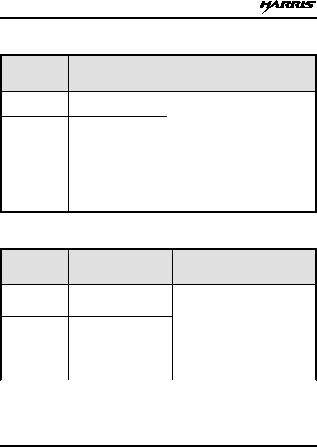
Table 1-1 through Table 1-3 list the recommended minimum safe lateral distances for a
controlled environment and for unaware bystanders in an uncontrolled environment,
from transmitting antennas (i.e., monopoles over a ground plane, or dipoles). Table 1-1
and Table 1-2 have the distances for the respective VRMS section of the vehicular
repeater on a per antenna basis. Table 1-3 has the distances for the VRBS section of the
vehicular repeater on a per antenna basis. This data is based upon the mobile radio
installed in a motor vehicle with the radio transmitting at its rated RF power level.
Transmit only when unaware bystanders are at least the uncontrolled recommended
minimum safe lateral distance away from the mobile radio’s transmitting antenna.

MM-018336-001, Rev. B
8
Table 1-1: Recommended Minimum Safe Lateral Distance
from Transmitting Antenna for Mobile Radio-to-Network Radio Link
(VRMS7010/VRMS7020 Transmit/Receive Antenna)
ANTENNA
PART NUMBER ANTENNA DESCRIPTION
RECOMMENDED MINIMUM LATERAL HUMAN BODY
DISTANCE FROM TRANSMITTING ANTENNA
CONTROLLED
ENVIRONMENT UNCONTROLLED
ENVIRONMENT
AN-125001-002
(mount) with
AN-225001-001
(element)
700/800 MHz Standard
Rooftop-Mount;
3 dBd Gain
9.8 Inches
(25 Centimeters) 21.7 Inches
(55 Centimeters)
AN-125001-002
(mount) with
AN-225001-002
(element)
700/800 MHz Standard
Rooftop-Mount;
Elevated-Feed 3 dBd Gain
AN-125001-002
(mount) with
AN-225001-003
(element)
700/800 MHz Standard
Rooftop-Mount;
Elevated-Feed, No Ground Plane
3 dBd Gain
AN-125001-002
(mount) with
AN-225001-004
(element)
700/800 MHz Standard
Rooftop-Mount;
Low-Profile 2 dBd Gain
AN-125001-002
(mount) with
AN-225001-005
(element)
700/800 MHz Standard
Rooftop-Mount;
5 dBd Gain
11.8 Inches
(30 Centimeters) 23.6 Inches
(60 Centimeters)
AN-125001-004
(mount) with
AN-225001-001
(element)
700/800 MHz Thick
Rooftop-Mount;
3 dBd Gain
9.8 Inches
(25 Centimeters) 21.7 Inches
(55 Centimeters)
AN-125001-004
(mount) with
AN-225001-002
(element)
700/800 MHz Thick
Rooftop-Mount;
Elevated-Feed 3 dBd Gain
AN-125001-004
(mount) with
AN-225001-003
(element)
700/800 MHz Thick
Rooftop-Mount;
Elevated-Feed, No Ground Plane
3 dBd Gain
AN-125001-004
(mount) with
AN-225001-004
(element)
700/800 MHz Thick
Rooftop-Mount;
Low-Profile 2 dBd Gain
AN-125001-004
(mount) with
AN-225001-005
(element)
700/800 MHz Thick
Rooftop-Mount;
5 dBd Gain
11.8 Inches
(30 Centimeters) 23.6 Inches
(60 Centimeters)
(Table Continued on Next Page)

MM-018336-001, Rev. B
9
Table 1-1: Recommended Minimum Safe Lateral Distance
from Transmitting Antenna for Mobile Radio-to-Network Radio Link
(VRMS7010/VRMS7020 Transmit/Receive Antenna)
ANTENNA
PART NUMBER ANTENNA DESCRIPTION
RECOMMENDED MINIMUM LATERAL HUMAN BODY
DISTANCE FROM TRANSMITTING ANTENNA
CONTROLLED
ENVIRONMENT UNCONTROLLED
ENVIRONMENT
AN-125001-006
(mount) with
AN-225001-001
(element)
700/800 MHz GPS Combo
Rooftop-Mount;
3 dBd / 5.15 dBi Gain
9.8 Inches
(25 Centimeters) 21.7 Inches
(55 Centimeters)
AN-125001-006
(mount) with
AN-225001-002
(element)
700/800 MHz GPS Combo
Rooftop-Mount;
Elevated-Feed 3 dBd Gain
AN-125001-006
(mount) with
AN-225001-003
(element)
700/800 MHz GPS Combo
Rooftop-Mount;
Elevated-Feed, No Ground Plane
3 dBd Gain
AN-125001-006
(mount) with
AN-225001-004
(element)
700/800 MHz GPS Combo
Rooftop-Mount;
Low-Profile 2 dBd Gain
AN-125001-006
(mount) with
AN-225001-005
(element)
700/800 MHz GPS Combo
Rooftop-Mount;
5 dBd / 7.15 dBi Gain
11.8 Inches
(30 Centimeters) 23.6 Inches
(60 Centimeters)
AN-125001-008
(mount) with
AN-225001-001
(element)
700/800 MHz Magnetic-Mount;
3 dBd Gain
9.8 Inches
(25 Centimeters) 21.7 Inches
(55 Centimeters)
AN-125001-008
(mount) with
AN-225001-002
(element)
700/800 MHz Magnetic-Mount;
Elevated-Feed 3 dBd Gain
AN-125001-008
(mount) with
AN-225001-003
(element)
700/800 MHz Magnetic-Mount;
Elevated-Feed, No Ground Plane
3 dBd Gain
AN-125001-008
(mount) with
AN-225001-004
(element)
700/800 MHz Magnetic-Mount;
Low-Profile 2 dBd Gain
AN-125001-008
(mount) with
AN-225001-005
(element)
700/800 MHz Magnetic-Mount;
5 dBd Gain 11.8 Inches
(30 Centimeters) 23.6 Inches
(60 Centimeters)
MM-018336-001, Rev. B
10
Table 1-2: Recommended Minimum Safe Lateral Distance
from Transmitting Antenna for Mobile Radio-to-Network Radio Link
(VRMS7030 Transmit/Receive Antenna)
ANTENNA
PART NUMBER ANTENNA DESCRIPTION
RECOMMENDED MINIMUM LATERAL HUMAN BODY
DISTANCE FROM TRANSMITTING ANTENNA
CONTROLLED
ENVIRONMENT UNCONTROLLED
ENVIRONMENT
AN102800V1 136 to 941 MHz, ¼-Wavelength*,
Standard Rooftop-Mount;
0 dBd Gain
24.8 Inches
(63 Centimeters) 55.1 Inches
(140 Centimeters)
AN-125001-001
(mount) with
AN-225002-001
(element)
136 to 174 MHz,
Standard Rooftop-Mount;
0 dBd Gain
AN-125001-003
(mount) with
AN-225002-001
(element)
136 to 174 MHz,
Thick Rooftop-Mount;
0 dBd Gain
AN-125001-007
(mount) with
AN-225002-001
(element)
136 to 174 MHz,
Magnetic-Mount;
0 dBd Gain
Table 1-3: Recommended Minimum Safe Lateral Distance
from Transmitting Antenna for Vehicular Repeater-to-Portable Radio Link
(VRBS7010/VRBS7020/VRBS7030 Transmit/Receive Antenna)
ANTENNA
PART NUMBER ANTENNA DESCRIPTION
RECOMMENDED MINIMUM LATERAL HUMAN
BODY DISTANCE FROM TRANSMITTING ANTENNA
CONTROLLED
ENVIRONMENT UNCONTROLLED
ENVIRONMENT
AN-125001-002
(mount) with
AN-225001-004
(element)
Standard Rooftop-Mount with Low-
Loss Cable and 700/800 MHz Low-
Profile 2 dBd Gain Element
7.9 Inches
(20 Centimeters) 7.9 Inches
(20 Centimeters)
AN-125001-004
(mount) with
AN-225001-004
(element)
Thick Rooftop-Mount with Low-Loss
Cable and 700/800 MHz Low-Profile
2 dBd Gain Element
AN-125001-008
(mount) with
AN-225001-004
(element)
Magnetic-Mount with Low-Loss
Cable and 700/800 MHz Low-Profile
2 dBd Gain Element
1.3.1 Mobile Antennas
The antennas for the radio must be installed in accordance with guidelines and procedures contained in
the Installation and Product Safety Manual. These mobile antenna installation guidelines are limited to

MM-018336-001, Rev. B
11
metal body motor vehicles or vehicles with appropriate ground planes. The antenna must be installed in
accordance with:
• The requirements of the antenna manufacturer/supplier included with the antenna.
• Instructions in the Installation and Product Safety Manual, including minimum antenna cable lengths.
The Installation and Product Safety Manual contains specific information on how to install the
antennas to facilitate recommended operating distances to all potentially exposed persons.
Use only the Harris-approved/supplied antenna(s), or an approved replacement antenna. Unauthorized
antennas, modifications, or attachments could damage the radio and may violate FCC regulations.
1.3.2 Approved Accessories
The radio has been tested and meets FCC RF guidelines when used with accessories supplied or
designated for use with it. Use of other accessories may not ensure compliance with the FCC’s RF
exposure guidelines, and may violate FCC regulations.
For a list of approved accessories refer to the product manuals, the Products and Services Catalog, or
contact Harris Corporation at 1-800-368-3277.
1.3.3 Contact Information
For additional information on exposure requirements or other information, contact Harris Corporation at
1-800-528-7711 or at www.pspc.harris.com.
1.4 RADIO FREQUENCY INTERFERENCE
1.4.1 FCC Part 15
This device complies with Part 15 of the FCC Rules. Operation is subject to the following two conditions:
1. This device may not cause harmful interference, and
2. This device must accept any interference received, including interference that may cause undesired
operation.
1.4.2 Industry Canada
This device complies with Industry Canada license-exempt RSS standard(s). Operation is subject to the
following two conditions: (1) this device may not cause interference, and (2) this device must accept any
interference, including interference that may cause undesired operation of the device.
Le présent appareil est conforme aux CNR d'Industrie Canada applicables aux appareils radio exempts de
licence. L'exploitation est autorisée aux deux conditions suivantes : (1) l'appareil ne doit pas produire de
brouillage, et (2) l'utilisateur de l'appareil doit accepter tout brouillage radioélectrique subi, même si le
brouillage est susceptible d'en compromettre le fonctionnement.
1.5 OCCUPATIONAL SAFETY GUIDELINES AND SAFETY TRAINING
INFORMATION
To ensure bodily exposure to RF electromagnetic energy is within the FCC allowable limits for
occupational use, always adhere to the following basic guidelines:
• The push-to-talk button should only be depressed when intending to send a voice message.
• The radio should only be used for necessary work-related communications.
MM-018336-001, Rev. B
12
• The radio should only be used by authorized and trained personnel. It should never be operated by
children.
• Do not attempt any unauthorized modification to the radio. Changes or modifications to the radio may
cause harmful interference and/or cause it to exceed FCC RF exposure limits. Only qualified
personnel should service the radio.
• Always use only Harris-authorized accessories (antennas, control heads, speakers/mics, etc.). Use of
unauthorized accessories can cause the FCC RF exposure compliance requirements to be exceeded.
The information listed above provides the user with information needed to make him or her aware of a RF
exposure, and what to do to assure that this radio operates within the FCC exposure limits of this radio.
1.6 COMMON HAZARDS
WARNING
The operator of any mobile radio should be aware of certain hazards common to
the operation of vehicular radio transmissions. Possible hazards include but are
not limited to:
• Explosive Atmospheres — Just as it is dangerous to fuel a vehicle with its engine is running, be sure
to turn the radio OFF while fuelling the vehicle. If the radio is mounted in the trunk of the vehicle,
DO NOT carry containers of fuel in the trunk.
Areas with potentially explosive atmosphere are often, but not always, clearly marked. Turn the radio
OFF when in any area with a potentially explosive atmosphere. It is rare, but not impossible that the
radio or its accessories could generate sparks.
• Interference To Vehicular Electronic Systems — Electronic fuel injection systems, electronic anti-
skid braking systems, electronic cruise control systems, etc., are typical of the types of electronic
devices that can malfunction due to the lack of protection from radio frequency (RF) energy present
when transmitting. If the vehicle contains such equipment, consult the dealer for the make of vehicle
and enlist his aid in determining if such electronic circuits perform normally when the radio is
transmitting.
• Electric Blasting Caps — To prevent accidental detonation of electric blasting caps, DO NOT use
two-way radios within 1000 feet (305 meters) of blasting operations. Always obey the “Turn Off
Two-Way Radios” (or equivalent) signs posted where electric blasting caps are being used. (OSHA
Standard: 1926.900).
• Radio Frequency Energy — To prevent burns or related physical injury from radio frequency
energy, do not operate the transmitter when anyone outside of the vehicle is within the minimum safe
distance from the antenna as specified in Table 1-1 and Table 1-3. Refer to Section 1.2 for additional
information.
• Vehicles Powered By Liquefied Petroleum (LP) Gas — Radio installation in vehicles powered by
liquefied petroleum gas, where the LP gas container is located in the trunk or other sealed-off space
within the interior of the vehicle, must conform to the National Fire Protection Association standard
NFPA 58. This requires:
The space containing the radio equipment must be isolated and sealed from the space containing
the LP gas container and its fittings.
Outside filling connections must be used for the LP gas container.
The LP gas container space shall be vented to the outside of the vehicle.

MM-018336-001, Rev. B
13
• Vehicles Equipped with Airbags — For driver and passenger safety, avoid mounting the radio’s
control head (or any other component) above or near airbag deployment areas. In addition to driver-
side and passenger-side front-impact airbags, some vehicles may also be equipped with side-impact
airbags. For occupant safety, verify the location of all airbags within the vehicle before installing the
radio equipment.
1.7 SAFE DRIVING RECOMMENDATIONS
The American Automobile Association (AAA) advocates the following key safe driving recommenda-
tions:
• Read the literature on the safe operation of the radio.
• Keep both hands on the steering wheel and the microphone in its hanger whenever the vehicle is in
motion.
• Place calls only when the vehicle is stopped.
• When talking from a moving vehicle is unavoidable, drive in the slower lane. Keep conversations
brief.
• If a conversation requires taking notes or complex thought, stop the vehicle in a safe place and
continue the call.
• Whenever using a mobile radio, exercise caution.
1.8 OPERATING RULES REGULATIONS
Two-way radio systems must be operated in accordance with the rules and regulations of the local,
regional, or national government.
In the United States, the P25 Vehicular Repeater System must be operated in accordance with the rules
and regulations of the Federal Communications Commission (FCC). Operators of two-way radio
equipment, must be thoroughly familiar with the rules that apply to the particular type of radio operation.
Following these rules helps eliminate confusion, assures the most efficient use of the existing radio
channels, and results in a smoothly functioning radio network.
When using a two-way radio, remember these rules:
• It is a violation of FCC rules to interrupt any distress or emergency message. The radio operates in
much the same way as a telephone “party line.” Therefore, always listen to make sure the channel is
clear before transmitting. Emergency calls have priority over all other messages. If someone is
sending an emergency message – such as reporting a fire or asking for help in an accident, do not
transmit unless assistance can be offered.
• The use of profane or obscene language is prohibited by Federal law.
• It is against the law to send false call letters or false distress or emergency messages. The FCC
requires keeping conversations brief and confined to business. Use coded messages whenever
possible to save on-the-air time.
• Using the radio to send personal messages (except in an emergency) is a violation of FCC rules. Send
only essential messages.
• It is against Federal law to repeat or otherwise make known anything overheard on the radio.
Conversations between others sharing the channel must be regarded as confidential.
• The FCC requires self-identification at certain specific times by means of call letters. Refer to the
rules that apply to the particular type of operation for the proper procedure.

MM-018336-001, Rev. B
14
• No changes or adjustments shall be made to the equipment except by an authorized or certified
electronics technician.
CAUTION
Under U.S. law, operation of an unlicensed radio transmitter within the jurisdiction of
the United States may be punishable by a fine of up to $10,000, imprisonment for up to
two (2) years, or both.
1.9 OPERATING TIPS
The following conditions tend to reduce the effective range of two-way radios and should be avoided
whenever possible:
• Operating the radio in areas of low terrain, or while under power lines or bridges.
• Obstructions such as mountains and buildings.
NOTE
In ar
eas where transmission or reception is poor, communication improvement may
sometimes be obtained by moving a few yards in another direction, or moving to a
higher elevation.
MM-018336-001, Rev. B
15
2 INTRODUCTION
2.1 VRS7000 SERIES OF P25 VEHICULAR REPEATERS
The VRS7000 series of Project 25 (P25) vehicular repeaters includes the three (3) distinctly different P25
Vehicular Repeater Systems: the VRS7010, the VRS7020, and the VRS7030. Unless otherwise stated,
operating procedures presented in this manual apply to all three (3) repeaters. Each repeater has different
radio frequency bands upon which it operates on. These bands are included in Figure 2-1 on page 15.
Henceforth, any reference of “VRS7000” in this manual applies to all three (3) P25
vehicular repeater systems, unless otherwise stated.
The VRS7000 vehicular repeater serves two functions. First, it can function as a standard mobile radio for
P25 trunked and P25 conventional radio networks. Second, it can function as a vehicular repeater in a P25
trunked radio network.
The VRS7000 cannot operate as a vehicular repeater when it is operating as a mobile radio. Likewise, it
cannot operate as a mobile radio when it is operating as a vehicular repeater.
As of the publication of this manual, only Harris-made P25 trunked radios can connect
to (i.e., be “clients” of) a VRS7000 vehicular repeater when it is operating as a
vehicular repeater.
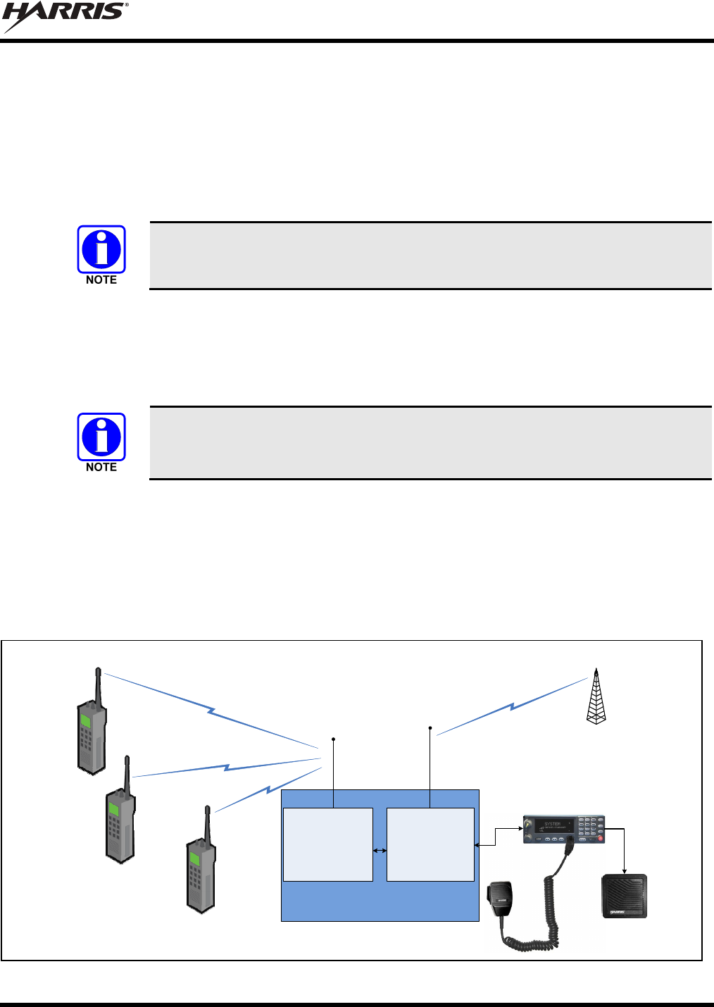
The VRS7000 consists of two (2) mobile radio systems coupled together with specialized interface
hardware. As illustrated in Figure 2-1, its Vehicular Repeater Mobile System (VRMS) provides the radio
frequency (RF) link to the radio network, and the Vehicular Repeater Base System (VRBS) provides the
RF link for nearby P25 radios. A control head, microphone speaker, and two (2) antennas complete the
radio installation.
The VRS7000 has two (2) primary operating modes as described in the following section.
VRS7010/VRS7020/VRS7030
P25 Vehicular Repeater System
Nearby Harris
P25 Radios
(e.g., P7200 and
P7300 Portable
Radios)
P25 Trunked Radio Network
RF Link
P25 Trunked
Base Station
VRBS
(VRBS7010: 700 MHz)
(VRBS7020: 800 MHz)
(VRBS7030: 700/800 MHz)
Client Radio-to-Vehicular Repeater
RF Links
Vehicle-Mounted
Antenna
Vehicle-Mounted
Antenna
VRMS
(VRMS7010: 800 MHz)
(VRMS7020: 700 MHz)
(VRMS7030: VHF)
CH-721 System Model
Control Head
Speaker
Microphone
P25
Client
Radio
P25
Client
Radio
P25
Client
Radio
Figure 2-1: Simplified Block Diagram of Extended Coverage (XCOV) Vehicular Repeater Mode

MM-018336-001, Rev. B
16
2.1.1 Primary Operating Modes
2.1.1.1 Mobile Radio Mode (Vehicular Repeater Disabled)
The VRS7000 operates like a normal mobile radio when its vehicular repeater mode is disabled. In this
case, the VRS7000 operates on and provides communications via a P25 trunked or P25 conventional
radio system. Radio control and voice communications are accomplished via the radio’s control head, the
“push-to-talk” (PTT) type microphone, and the speaker connected to the control head. Using the control
head, microphone and speaker, the user/operator can control the radio and communicate with other radio
users and console dispatchers on the radio network.
In this mode, nearby P25 radio users can only communicate with the VRS7000 radio user/operator if they
can also directly access the same radio network. Since the vehicular repeater functionality of the
VRS7000 is completely disabled in the mobile radio mode, nearby P25 radios cannot link through the
VRS7000 to the radio network.
Instructions on using the mobile radio mode are included in Section 4 of this manual.
2.1.1.2 Extended Coverage (XCOV) Vehicular Repeater Mode
When the VRS7000 is operating in the extended coverage vehicular repeater mode, it provides the
network extension that enables nearby P25 radios operating on a vehicular repeater radio frequency
channel to access a P25 trunked radio network. This mode of operation is sometimes abbreviated
“vehicular repeater mode” or simply “XCOV mode.” As illustrated in Figure 2-1, portable radio
coverage is extended due to the VRS7000’s high-performance mobile antenna system and higher
transmitter output power used to access the P25 trunked radio network. The VRS7000 can significantly
enhance in-building penetration for P25 trunked portable radios that can operate on the same radio
frequency band as the vehicular repeater. Typical operational scenarios include in-building tactical
operations and joint training exercises.
When a nearby P25 radio is communicating through the VRS7000, it is considered “connected” to or a
“client” on the VRS7000. The VRS7000 cannot function as a standard/normal mobile radio when it is
operating in the XCOV vehicular repeater mode. Instructions on enabling and disabling this VRS7000
mode are included in Section 3 of this manual.
P25 radio users connect to a VRS7000 by manually making a “system” change at the radio to connect to
an active VRS7000 vehicular repeater. After selecting a system allocated for VRS7000 vehicular repeater
operation, the radio then scans for an active vehicular repeater channel. Vehicular repeater channels are
pre-programmed into each P25 radio requiring operation on a VRS7000. A P25 radio can only connect to
a VRS7000 if the radio is registered for communications on the respective P25 trunked radio network.
After a P25 radio initially connects to a VRS7000, “REGISTER” briefly appears in the radio’s display.
This indicates the radio is registered on the P25 trunked radio network via the VRS7000. Therefore, the
radio can be used to communicate with other radio users on the radio network and with radios connected
to the VRS7000.
The VRS7000 operator can place the VRS7000 into XCOV vehicular repeater mode via a menu selection
or preset button press at the radio’s control head. Likewise, the operator can disable this mode via a
control head menu selection or preset button press. Alternately, the radio installation may be wired so this
mode can be enabled and disabled by an external switch located on the vehicle’s dash panel, console
panel, or elsewhere.
When the VRS7000 is operating in the XCOV vehicular repeater mode, it functions like a Voice and Data
Over Control (VDOC) site for the nearby P25 radios connected to it. Essentially, the P25 client radios and
the VRBS7000 are linked together via P25 VDOC protocols on the VRBS7000’s VDOC RF channel. If
properly programmed, both P25 portable and P25 mobile radios can connect to the VRS7000 when it is
operating in the XCOV vehicular repeater mode.

MM-018336-001, Rev. B
17
When using the XCOV vehicular repeater mode, P25 radios operating through the VRS7000 (i.e., “P25
client radios”) maintain the following P25 functions across the two RF links:
• P25 Group Call — P25 radios connected to the VRS7000 can communicate on a common talk
group, or on multiple different talk groups. When it is operating in the XCOV vehicular repeater
mode, the VRS7000 provides up to sixty-four (64) talk group paths (i.e., a different talk group
selected at each radio). Digital clear voice and digital encrypted voice group calls are supported.
• P25 Individual Call — Unit-to-unit calls between two P25 client radios and between a P25 client
radio and a radio/console on the P25 radio network are supported. Digital clear voice and digital
encrypted voice individual calls are supported.
• P25 User ID — Caller identification information is sent between a P25 client radio and the P25
trunked radio network.
• P25 Emergency — The link through the VRS7000 provides P25 emergency communications
between the P25 client radios and the P25 trunked radio network.
• P25 System All Call (from Network Only) — A system-wide all-call transmission from the P25
radio network is forwarded to P25 client radios.
• Call Grant and Call Queued Tones — A P25 client radio generates call grant and call queued tones
in a similar manner as if it is operating directly on the P25 radio network.
Up to sixty-four (64) P25 radios can connect to a VRS7000 at any given time, and these radio users can
communicate via the same talk group or via multiple different talk groups. Although up to sixty-four (64)
talk groups can be used by connected radios (i.e., a different talk group selected at each radio), excessive
call queuing can result when multiple talk groups and/or individual calls are utilized by the P25 client
radios. Refer to Section 2.3.5 on page 19 for additional information.
When operating in the extended coverage (XCOV) vehicular repeater mode, calls transmitted from the
P25 client radios are not routed to the VRS7000’s speaker. Refer to Section 2.3.3 on page 18 for
additional information.
The VRS7000 supports end-to-end Advanced Encryption Standard (AES) encrypted calls. If a P25 client
radio is transmitting an encrypted call, the VRS7000 simply repeats the call to the network base station. It
does not un-encrypt and then re-encrypt the call.
2.2 MULTIPLE ON-SCENE VEHICULAR REPEATERS
The VRS7000 P25 Vehicular Repeater System design supports multiple on-scene VRS7000s via multiple
radio frequency channels assigned for system-wide vehicular repeater use. When XCOV vehicular
repeater mode is enabled at a particular VRS7000, the VRS7000 automatically selects an unused pre-
programmed channel allocated for vehicular repeater operations after a scanning algorithm determines the
channel is available.
When multiple VRS7000s are on a scene, a P25 radio user must manually make a “system” change to
connect to a VRS7000. Subsequently, the P25 radio will scan for and, if properly registered, connect to an
available VRS7000 operating in the XCOV vehicular repeater mode. A P25 radio can only connect to a
VRS7000 if the radio is registered for communications on the respective P25 trunked radio network.
VRS7000s in the network can be configured so when a VRS7000 leaves a scene, P25 client radios
connected to it will automatically transition to a second on-scene VRS7000. This automatic hand-off
operation requires proper vehicular repeater channel/frequency configuration in all VRS7000s and P25
client radios. During the transition, each P25 client radio displays “CC SCAN” while it is searching for
another on-scene VRS7000.
MM-018336-001, Rev. B
18
NOTE
Vehicles equipped with a VRS7000 must maintain an antenna separation distance of at
least ten (10) feet during vehicular repeater operations.
2.3 LIMITATIONS OF THE VEHICULAR REPEATER
2.3.1 General Information
The VRS7000 P25 Vehicular Repeater System provides unique system advantages by extending network
coverage to nearby P25 radios operating in otherwise poor radio frequency coverage areas of the P25
trunked radio network. It can significantly improve radio communications for P25 portable radio users
operating in buildings or in other in-network weak-signal areas where portable radio communications is
otherwise problematic or not possible. However, the VRS7000 presents certain communication
limitations as described in this section.
NOTE
All users must be properly trained on correct vehicular repeater operating procedures.
This training should include but not be limited to familiarity with VRS7000
limitations, as described in the following subsections.
2.3.2 Limited Feature Set
When it is operating as a vehicular repeater, the VRS7000 cannot provide all the communication features
normally provided by a direct radio link to P25 trunked radio network. The VRS7000 is not intended to
replace the functionality of the P25 trunked radio network’s fixed RF base station/site equipment. The
VRS7000’s limited feature set for vehicular repeater operations is listed in Section 2.1.1.2 of this manual.
2.3.3 XCOV Vehicular Repeater Mode Disables Mobile Radio Mode
The VRS7000 P25 Vehicular Repeater System cannot function as a normal mobile radio when it is
operating as a vehicular repeater. The speaker and microphone connected to the control head are disabled
when the VRS7000 is operating as a vehicular repeater. Also, the control head does not indicate network-
only calls to the VRS7000, and other functions such as talk group scanning, are not possible. When the
VRS7000 is operating as a vehicular repeater, the control head primarily indicates vehicular repeater
mode-related operations.
2.3.4 Loss of Network Connectivity Disconnects Client Radios
If the VRS7000 P25 Vehicular Repeater System loses contact with the P25 trunked radio network that it
is currently logged into, it automatically scans for another control channel to maintain network
connectivity. During this time, a “CC SCAN” indication appears in the control head’s display to indicate
the VRS7000 is scanning/searching for a P25 radio network control channel. Also, if alert tones are
programmed on, an alert tone sounds in the speaker when the control channel scan begins. A control
channel scan can occur both when the vehicular repeater is operational/enabled (i.e., the VRS7000 is in
the XCOV vehicular repeater mode), and when the vehicular repeater is not operational (i.e., the
VRS7000 is in the mobile radio mode).
If the VRS7000 loses radio network connectivity for several seconds when the vehicular repeater is
operational/enabled (i.e., as indicated by “CC SCAN” in the control head’s display), it automatically
disconnects all connected P25 radio clients and disables XCOV vehicular repeater mode. In this case, all
P25 radios that were connected to the VRS7000 will themselves indicate the loss of connectivity with the
VRS7000 by also indicating control channel scan (“CC SCAN”), and by sounding an alert tone if
programmed to do so. After disconnecting, each P25 radio will automatically scan for another VRS7000
MM-018336-001, Rev. B
19
operating as a vehicular repeater. If another VRS7000 is found, the P25 radio will attempt to connect to
that VRS7000. If connection is successful, communications through the VRS7000 can continue. If
connection is not successful after a short period of time and radio communications must continue, the P25
radio user must manually make a “system” change to another available radio system, or select and use a
pre-programmed talk-around channel.
NOTE
When arriving at a scene, a vehicle with the VRS7000 must be located/positioned so it has
a reliable RF link to the P25 trunked radio system. If this is not the case, reposition the
vehicle to another location, such as
on the opposite side of the building, to reduce or
eliminate “CC SCAN” indications before enabling the XCOV vehicular repeater mode.
If a reliable RF link cannot be achieved in the mobile radio mode, do not enable/activate
the XCOV vehicular repeater mode. Using the XCOV vehicular repeater mode is not
recommended if, while in mobile radio mode, “CC SCAN” is indicated more than once
approximately every thirty (30) seconds.
2.3.5 One Talk Path
The VRS7000 P25 Vehicular Repeater System provides only one talk path for all P25 radios connected to
it. From the vehicular repeater standpoint, this is a single-channel full-duplex talk path to and from
connected/client P25 radios. Since there is only one talk path, significant call queuing can occur when
multiple P25 radios are attached to the VRS7000. To minimize call queuing, P25 client radio users
should minimize the total number of selected talk groups, and minimize individual call operations.
CAUTION
When P25 client radios are using more than one talk group and/or making
individual call(s), both calls originated from the P25 client radios to the network
and calls originated from the P25 trunked radio network to the P25 client radios
can be queued. All radio users and dispatchers must be aware of this fact when a
VRS7000 is in operation. When critical communications must be accomplished
through the VRS7000, it is recommended that all P25 client radio users utilize only
one (1) common talk group, and not make any individual calls.
2.3.6 Slight Audio Delay Between Client Radios and Network
Because of the extra signal processing performed within the VRS7000 to route calls, call audio between a
P25 radio connected to the VRS7000 and the P25 trunked radio network is delayed by approximately
one-quarter (¼) of a second. This time delay can be heard by simultaneously monitoring a talk group’s
call audio in the speakers of both a P25 radio connected to the VRS7000 and a P25 radio logged directly
onto the respective P25 trunked radio network.
2.3.7 Other Limitations
The VRS7000 P25 Vehicular Repeater System does not support the following features/functions when it
is operating as a vehicular repeater:
• Patched Talk Groups — When a talk group used by P25 radios connected to the VRS7000 is within a
patch (patches are created by dispatch personnel), call audio on other groups within the patch is not
routed to the P25 radios connected to a VRS7000. Also, call audio from a connected P25 radio on a
particular talk group within the patch is not routed to other groups within the patch.
• Simulselected Talk Groups — When a talk group used by P25 radios connected to the VRS7000 is
within simulselect (simulselects are created by dispatch personnel), call audio on other groups within
the simulselect is not routed to the P25 radios connected to a VRS7000.

MM-018336-001, Rev. B
20
• Interconnect (PSTN) Calls — Telephone interconnect calls cannot be placed by or received by a P25
radio connected to a VRS7000.
• Data Calls — Data calls, such as mobile data calls, cannot be sent to or received by a P25 radio
connected to a VRS7000.
• Message Trunked Calls — Message trunked calls cannot be sent to or received from a P25 radio
connected to a VRS7000. Repeater channel “hang times” associated with messaged trunked group
calls, emergency calls, and individual calls are not supported.
• Dynamic Regroup — Talk groups used by P25 radios connected to a VRS7000 cannot be
dynamically regrouped.
• Roaming — P25 radios connected to a VRS7000 cannot automatically roam to another system. The
radio operator must manually make a system change to access another radio system.
• Console Preempt when a P25 Client Radio is Keyed — A dispatcher cannot preempt a P25 radio
connected to a VRS7000 while the radio is transmitting on a talk group.
• Motorola-Style Emergency Calls — The VRS7000 does not support Motorola-style emergency calls
when it is operating in the XCOV vehicular repeater mode.
• Confirmed Unit-to-Unit Call — Unit-to-unit individual calls (“I-calls”) are not confirmed for P25
radios connected to the VRS7000.
• Acknowledged Unit-to-Unit Call — The acknowledged unit-to-unit individual (“I-call”) call feature
is not provided to P25 radios connected to the VRS7000.
• Vehicular Repeater Mode when Operating on a P25 Conventional Radio Network — The VRS7000
must be operating on (i.e., registered on) a P25 trunked radio network before the XCOV vehicular
repeater mode can be utilized.
• Talk Group Priorities — Talk groups used by P25 radios connected to the VRS7000 do not have talk
group priorities.
• Individual Call (I-Call) Block — Individual calls to and from P25 radios connected to the VRS7000
cannot be blocked.
• Subscriber Administration Rights — The VRS7000 does not support subscriber administration rights.
• Invalidated Talk Group Emergency — The VRS7000 does not support the invalid talk group
emergency feature.
• Mobile Radio Steering/Preempt — The VRS7000 does not support the mobile radio steering/preempt
feature.
• Global Positioning System (GPS) — GPS location request and report messages are not routed
through the VRS7000.
• Cross-Band Vehicular Repeater Operation — With the VRS7010 P25 vehicular repeater system,
client P25 radios connect to the VRS7010 via the 700 MHz radio frequency band, and the network
link is on the 800 MHz band. With the VRS7020 P25 vehicular repeater system, client P25 radios
connect to the VRS7020 via the 800 MHz radio frequency band, and the network link is on the
700 MHz band. With the VRS7030 vehicular repeater system, client P25 radios connect to the
VRS7030 via either the 700 MHz or the 800 MHz radio frequency band, and the network link is on
the VHF radio frequency band (136 to 174 MHz).
2.4 CH-721 SYSTEM MODEL CONTROL HEAD
The VRS7000 employs the CH-721 System model control head. Shown in Figure 4-1 on page 26, this
control head provides the user/operator interface for the VRS7000. The CH-721 System model control
head has a large easy-to-read 3-line graphical vacuum-fluorescent type display, an on/off/volume control
knob, menu controls, an emergency/home button, a scan on/off button, and three (3) preset buttons. It also

MM-018336-001, Rev. B
21
features a 12-key numeric keypad that provides Dual-Tone Multi-Frequency (DTMF) keypad functional-
ity and easier operator system/group selection, three (3) preset buttons, and an emergency/home button.
Other front panel components include a microphone connector and two (2) Light-Emitting Diode (LED)
type indictors. One LED indicator is the busy indicator that lights when the VRS7000 is receiving a call.
The other is the transmitter-enabled indicator that lights when it is transmitting. The control head’s
buttons and keys are backlit for nighttime operation. An ambient light sensor on the head’s front panel
controls automatic display and button/key backlight dimming.
MM-018336-001, Rev. B
22
3 VEHICULAR REPEATER OPERATION
3.1 TURNING ON THE VRS7000
To turn on the VRS7000, rotate the control head’s Power On/Off/Volume control knob clockwise out of
the detent position. The knob is shown in Figure 4-1 on page 26. This action powers-up the VRS7000 and
the control head. If enabled through programming, a short beep sounds in the speaker to indicate the radio
is ready for operation. The control head indicates the last selected system name on line 1 and the last
selected group name on line 2.
NOTE
At power-up, the VRS7000 begins operating
in the mobile radio mode. For
complete operating instructions for this mode, refer to Section 4 which begins on
page 26.
To enable/activate the vehicular repeater mode, refer to Section 3.2 that follows.
3.2 EXTENDED COVERAGE (XCOV) VEHICULAR REPEATER MODE
3.2.1 Switch to a P25 Trunked Radio System (if not currently selected)
Before XCOV vehicular repeater mode can be enabled/activated, the VRS7000 must be operating on a
P25 trunked radio system. Use one of the following methods to switch VRS7000 operation to a P25
trunked radio system:
3.2.1.1 Using the Ramp Control to Switch to a P25 Trunked Radio System
Use the control head’s ramp control to scroll through the menu until the desired P25 trunked radio
network’s name appears in the display. This ramp control is shown in Figure 4-1 on page 26. After a
short delay, the VRS7000 will switch to the newly selected P25 trunked radio network, and begin
operating on it. This is called a “system” change.
3.2.1.2 Using Keypad Entry to Switch to a P25 Trunked Radio System
1. Enter the “system” number of the respective P25 trunked radio network, per radio programming, via
the control head’s 12-key DTMF keypad. The front panel of the control head is shown in Figure 4-1
on page 26.
2. Press the MENU button to switch the VRS7000 to the entered P25 trunked radio network. After a
short delay, the VRS7000 will begin operating on the newly selected network.
There are (3) possible methods that can be used to enable and disable the extended coverage (XCOV)
vehicular repeater mode, as described in the following sections.
NOTE
When arriving at a scene, a vehicle with the VRS7000 must be located/positioned so it has
a reliable RF link to the P25 trunked radio system. If this is not the case, reposition the
vehicle to another location, such as
on the opposite side of the building, to reduce or
eliminate “CC SCAN” indications before enabling the XCOV vehicular repeater mode.
If a reliable RF link cannot be achieved in the mobile radio mode, do not enable/activate
the XCOV vehicular repeater mode. Using the XCOV vehicular repeater mode is not
recommended if, while in mobile radio mode, “CC SCAN” is indicated more than once
approximately every thirty (30) seconds.
MM-018336-001, Rev. B
23
3.2.2 Enable/Disable XCOV Vehicular Repeater Mode via the Control Head’s
Menu
To enable the XCOV vehicular repeater mode via the control head’s menu, follow this procedure:
1. If the VRS7000 is not currently operating on a P25 trunked radio network, use one of the two
methods presented in Section 3.2.1 to switch it to a P25 trunked radio network. The VRS7000 must
be operating on a P25 trunked radio network before XCOV vehicular repeater mode can be
enabled/activated.
2. Press the control head’s MENU button.
3. Use the control head’s ramp control to scroll through the menu until P25 VR appears in the
middle line of the display, and then press the MENU button again. Subsequent control head
indications are illustrated in Section 3.2.5.
4. With VR STANDBY or VR ACTIVE indicated, nearby P25 radio users with radios pre-programmed
for P25 vehicular repeater operations can now connect to the VRS7000 by manually making a
“system” change to the respective vehicular repeater channel. If necessary, consult with the radio
network administration personnel or a communications supervisor for specific vehicular repeater
system name(s).
CAUTION
When X
COV vehicular repeater mode is enabled/active, normal mobile radio
communications are not possible with the VRS7000. In other words, the speaker and
microphone connected to the CH-721 control head do not
function when XCOV
vehicular repeater mode is enabled/active.
To disable XCOV vehicular repeater mode, if no menu change has been made since it was enabled, press
the MENU button to toggle the mode off. If a menu change has occurred since it was enabled, first press
the MENU button, navigate to the P25 VR menu again, and then press the MENU button again. The
VRS7000 will return to a normal display, indicating network talk group and/or individual call
information.
3.2.3 Enable/Disable XCOV Vehicular Repeater Mode via Control Head Button
(If Programmed)
The VRS7000 can be configured so a button on the control head can be pressed to enable and disable the
XCOV vehicular repeater mode. Typically, one of the three (3) preset buttons (A, B, or C) located just
below the control head’s display is configured for this function. Before using this procedure, consult with
the system administrator to determine if the VRS7000 is configured in this manner, and which button has
been configured for this function:
1. If the VRS7000 is not currently operating on a P25 trunked radio network, use one of the two
methods presented in Section 3.2.1 to switch it to a P25 trunked radio network. The VRS7000 must
be operating on a P25 trunked radio network before XCOV vehicular repeater mode can be
enabled/activated.
2. Press the button to enable XCOV vehicular repeater mode. Subsequent control head indications are
illustrated in Section 3.2.5.
3. With VR STANDBY or VR ACTIVE indicated, nearby P25 radio users with radios pre-programmed
for P25 vehicular repeater operations can now connect to the VRS7000 by manually making a
“system” change to the respective vehicular repeater channel. If necessary, consult with the radio
network administration personnel or a communications supervisor for specific vehicular repeater
system name(s).
MM-018336-001, Rev. B
24
To disable XCOV vehicular repeater mode, press the same button again, or press the MENU button. The
VRS7000 will return to a normal display, indicating network group and/or individual call information.
3.2.4 Enable/Disable XCOV Vehicular Repeater Mode via External Switch
The VRS7000 installation may be wired to an external switch used to enable and disable the XCOV
vehicular repeater mode. The external switch may be located on the vehicle’s dash panel, on a console
panel near the control head, or elsewhere. Follow this procedure to enable XCOV vehicular repeater
mode via an external switch:
1. If the VRS7000 is not currently operating on a P25 trunked radio network, use one of the two
methods presented in Section 3.2.1 to switch it to a P25 trunked radio network. The VRS7000 must
be operating on a P25 trunked radio network before XCOV vehicular repeater mode can be
enabled/activated.
2. Place the external switch in the enabled/activated position. Subsequent control head indications are
illustrated in Section 3.2.5.
3. With VR STANDBY or VR ACTIVE indicated, nearby P25 radio users with radios pre-programmed
for P25 vehicular repeater operations can now connect to the VRS7000 by manually making a
“system” change to the respective vehicular repeater channel. If necessary, consult with the radio
network administration personnel or a communications supervisor for specific vehicular repeater
system name(s).
To disable the XCOV vehicular repeater mode, place the external switch in the disabled/deactivated
position. The VRS7000 will return to a normal display, indicating network group and/or individual call
information.
NOTE
The VRS7000 can also be configured so the external switch must be activated and a
pre-configured button on the control head must be
pressed to enable the XCOV
vehicular repeater mode. In this case, to disable the mode, simply press the same
button again or return the switch to the disable position.
NOTE
Other radio installation options also exist. For example, the VRS7000 can be wired so
the XCOV vehicular repeater mode automatically activates/enables when a portable
radio is removed from an in-vehicle charger. C
onsult with the radio network
administration personnel or a communications supervisor for additional information.
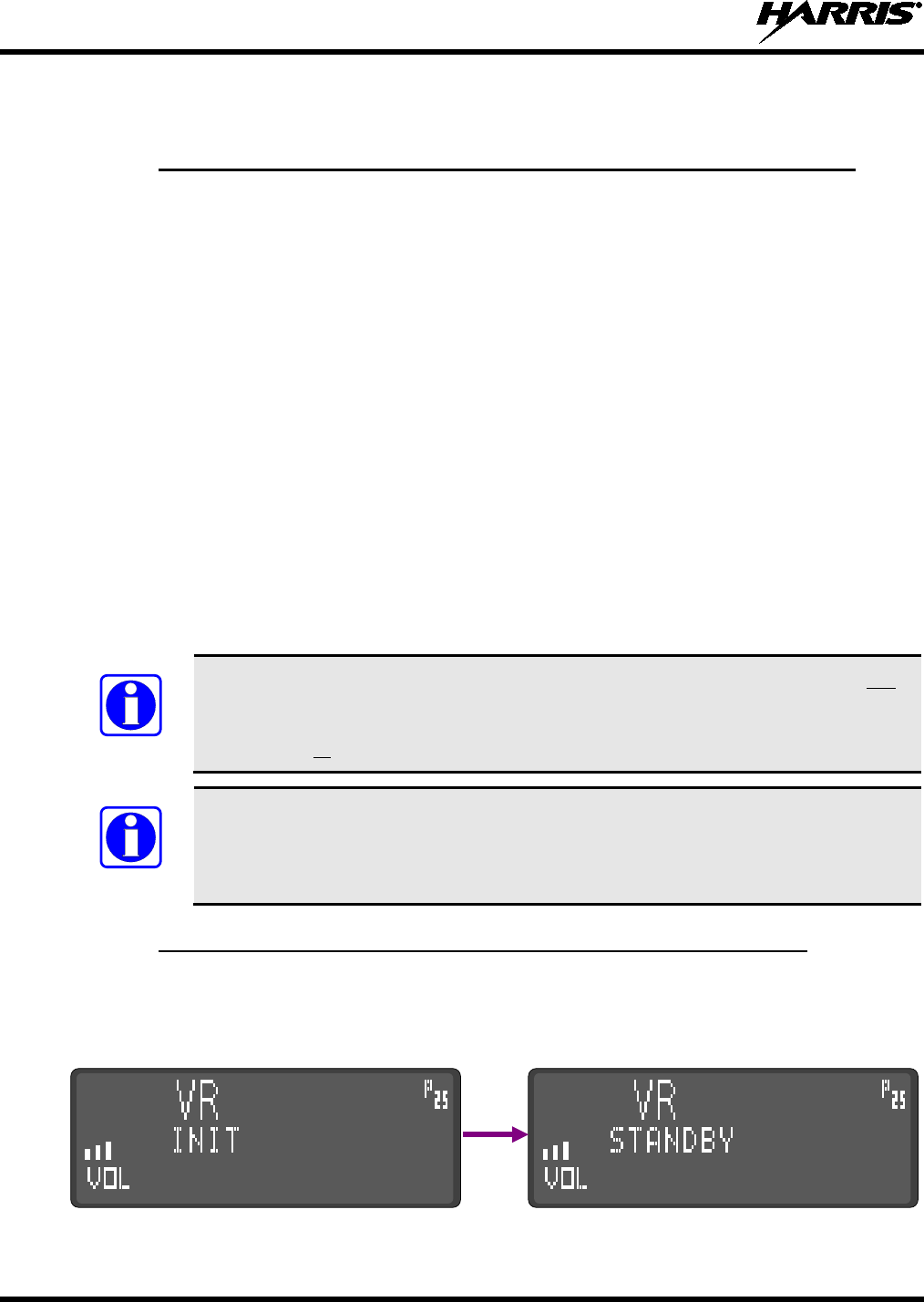
3.2.5 Indications During XCOV Vehicular Repeater Mode Operations
When the XCOV vehicular repeater mode is activated/enabled VR INIT appears briefly in the display
followed by VR STANDBY. VR INIT indicates the initialization/startup of the VRS7000 into XCOV
vehicular repeater mode. VR STANDBY indicates the VRS7000 is operating in the XCOV vehicular
repeater mode without any P25 client radios connected.
Figure 3-1: Control Head Indications during Vehicular Repeater Initialization
MM-018336-001, Rev. B
25
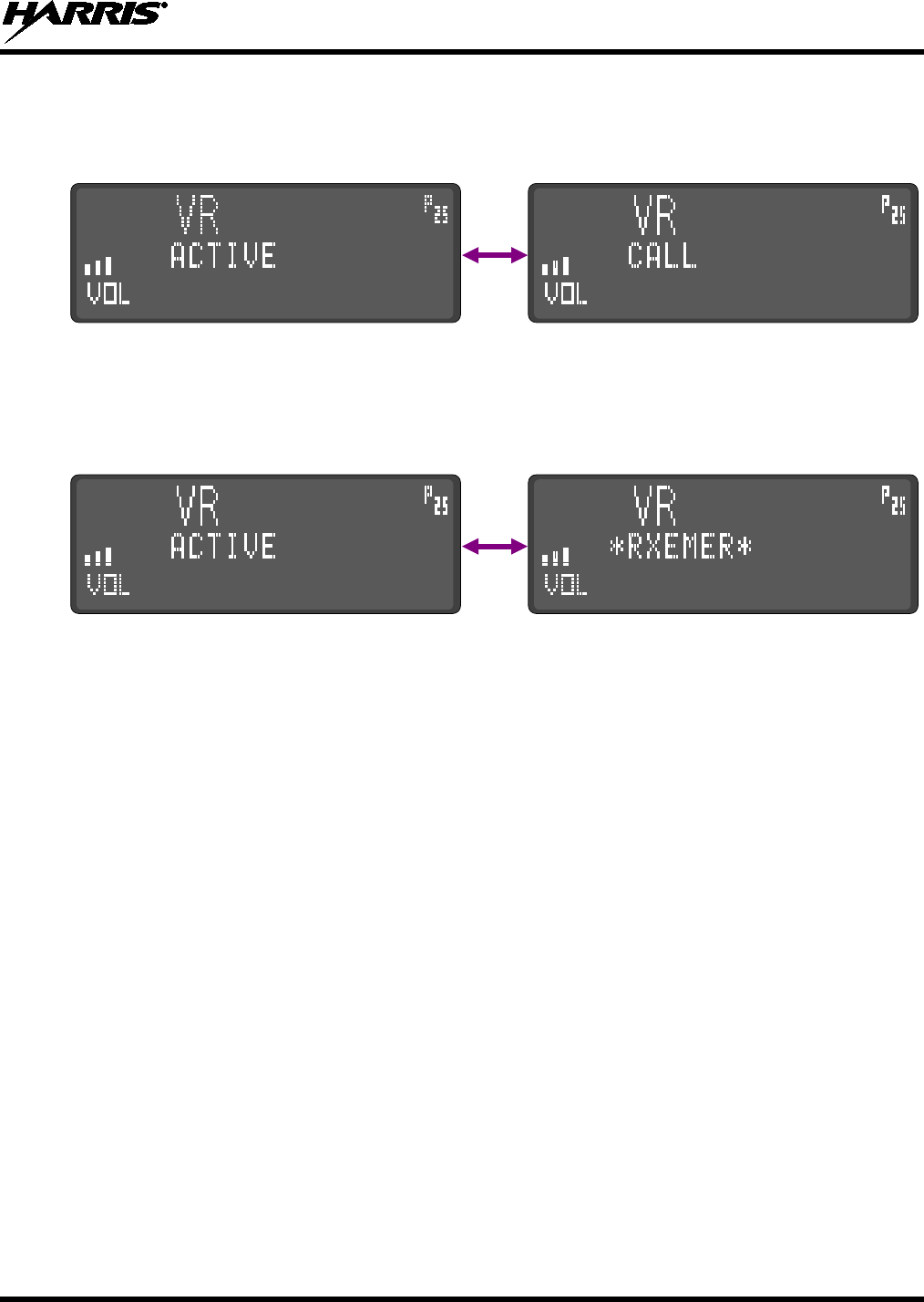
When one or more P25 client radios connect to the VRS7000, VR ACTIVE appears in the display. When
a call is made from a P25 client radio or from a radio on the network (on a talk group also being used by
the P25 client radios), VR CALL appears in the control head’s display. The VR CALL indication
replaces the VR ACTIVE indication during the call.
Figure 3-2: Control Head Indications with P25 Client Radio(s) Connected
and a Call from a P25 Client Radio or from the Radio Network
When an emergency is declared on a talk group being used by the P25 client radio(s), VR RXEMER
appears in the control head’s display. VR RXEMER also appears when any radio (client or network)
transmits on an emergency group currently being used by the P25 client radio(s).
Figure 3-3: Control Head Indications with P25 Client Radio(s) Connected
and an Emergency Call on a Vehicular Repeater Talk Group
MM-018336-001, Rev. B
26
4 MOBILE RADIO OPERATION
This section describes radio operations when the VRS7000 is operating as a normal mobile radio. For
vehicular repeater operations, refer to Section 3 which begins on page 22.
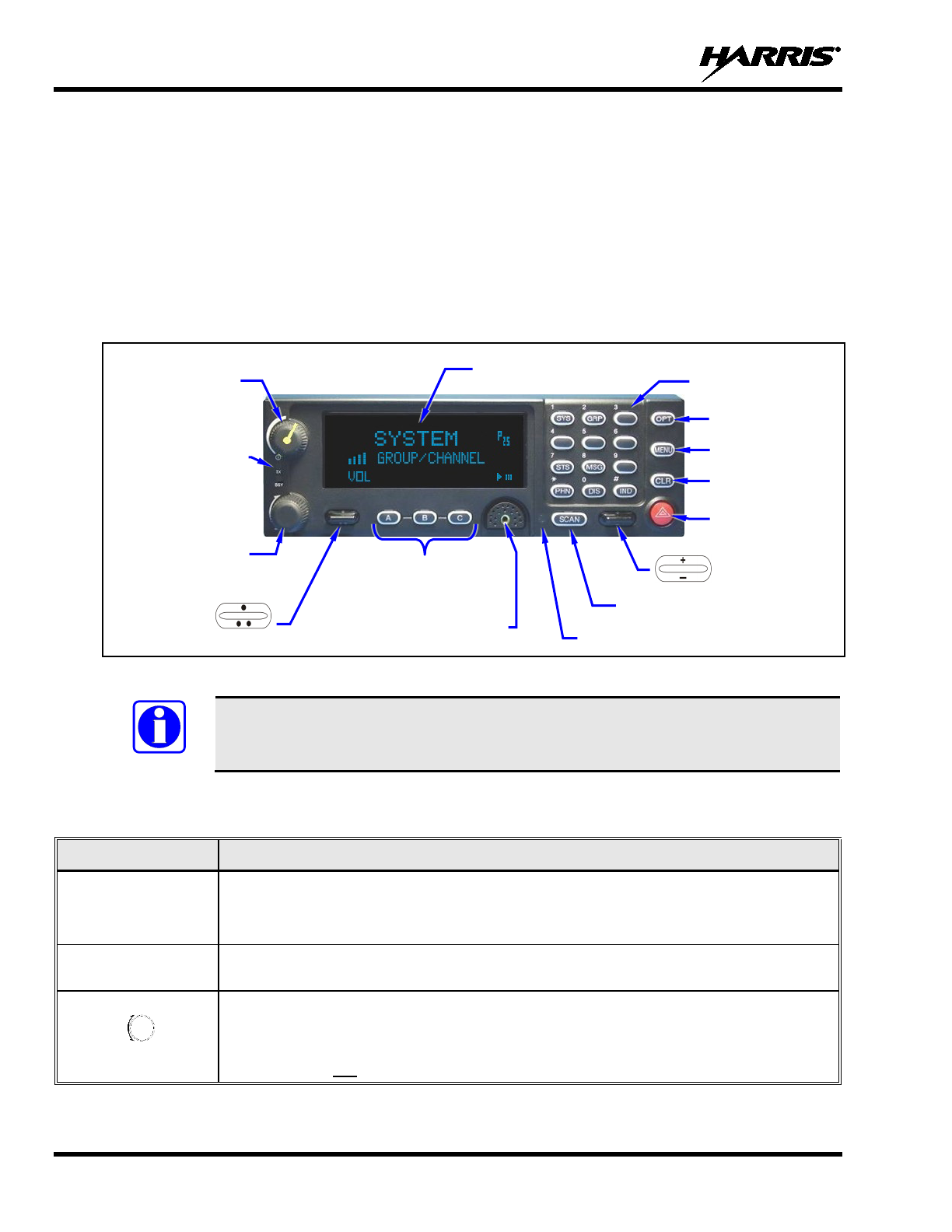
4.1 FRONT PANEL OF THE CONTROL HEAD
The front panel of the CH-721 System model control head includes a dot matrix display, ramp control and
buttons for menu navigation, an emergency/home button, three (3) pre-set buttons, a power on/off/volume
control knob, a microphone connector, and a 12-key DTMF keypad. Table 4-1 summarizes functions of
the front panel controls.
Figure 4-1: CH-721 System Model Control Head
NOTE
Button and key functions may vary depending upon system programming, radio
hardware, and optional configurations. The table in Section 6 is provided to record
functions of remapped buttons/keys
Table 4-1: Controls of CH-721 System Model Control Head
CONTROL FUNCTION
Power
On/Off/Volume
Control Knob
Turn this knob clockwise to turn on the VRS7000, and to increase volume.
See Section
3.1 on page 22 for additional information.
Turn this knob counter-clockwise to decrease volume, and to turn off the VRS7000.
Ambient Light
Sensor Radio automatically adjusts the display and button/key back
light brightness level based
on ambient light. Do not block this sensor.
System/Group Knob
When the vehicular repeater is disabled/inactive, use the System/Group knob to select a
system/group combination, based upon radio programming. See Section 4.7
which
begins on page 32 for additional information.
This knob does not function when the vehicular repeater is enabled/active.
3-Line Graphical Vacuum-
Fluorescent Display
Microphone Connector
Power On/Off/-
Volume
Control Knob
Ramp Control
Emergency/
Home Button
Ramp Control
Ambient Light-Level Sensor
Transmit (TX)
and Busy (BSY)
Indicators
Scan On/Off Button
Clear Button
Menu Button
Option Button
System/Group
Knob
Preset Buttons
12-Key DTMF
Keypad
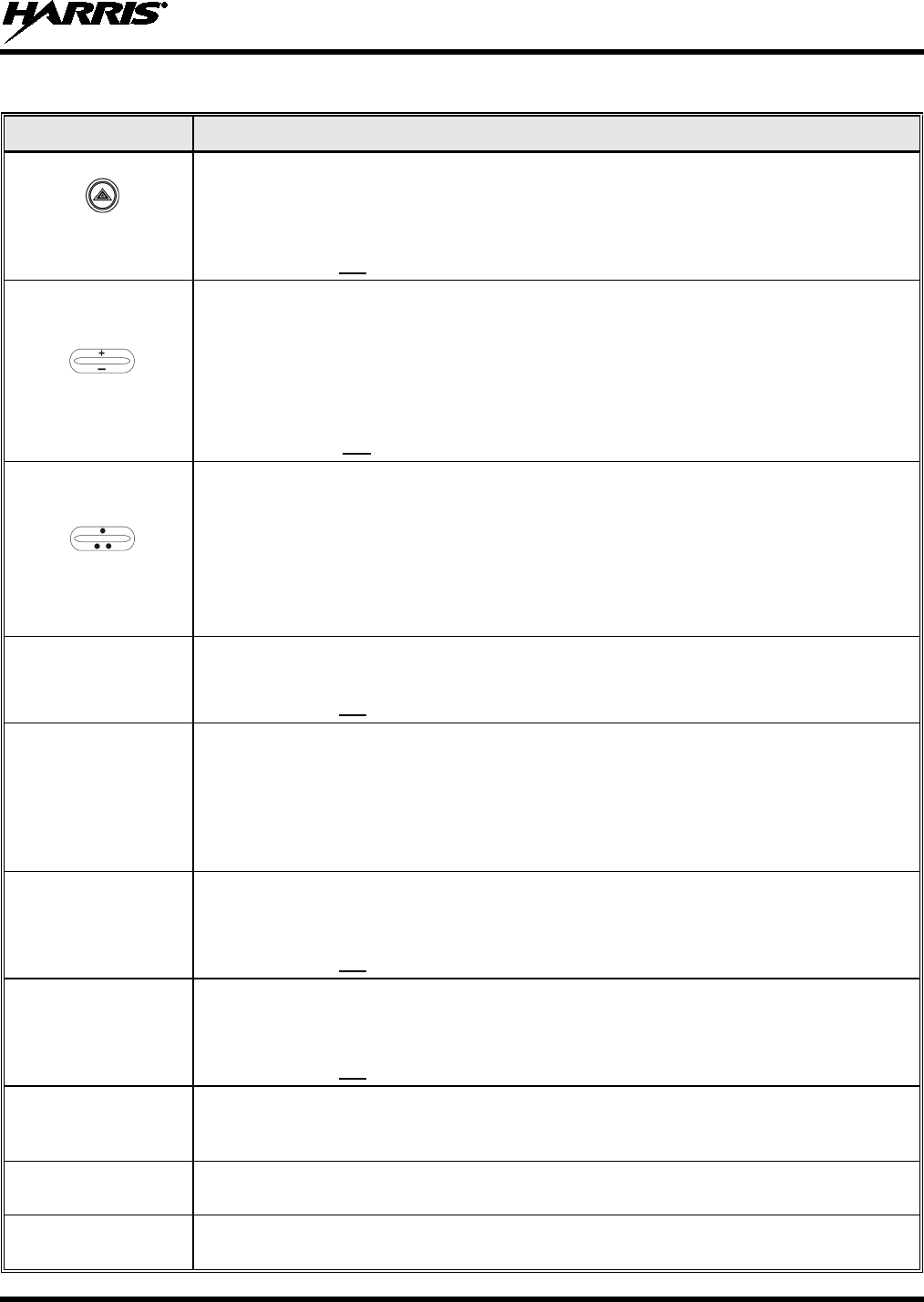
MM-018336-001, Rev. B
27
Table 4-1: Controls of CH-721 System Model Control Head
CONTROL FUNCTION
Emergency/Home
Button
When the vehicular repeater is disabled/inactive, use the Emergency/Home button
to
declare an emergency, if the emergency feature is enabled. See Section 4.17
on page
43 for additional information. Alternately, this button can also be programmed to switch
the radio to a home group when it is pressed.
This button does not function when the vehicular repeater is enabled/active.
Ramp Control
This rocker-type ramp control has multiple functions.
When the vehicular repeater is disabled/inactive, it is used to display the current scan
status for a group, and to then add or delete the group from the system scan list.
See
Section 4.19 which begins on page 45 for additional information.
It is also used for various other selection-
type functions, as described elsewhere in this
manual.
This control does not function when the vehicular repeater is enabled/active.
Ramp Control
This rocker-type ramp control also has multiple functions.
When the vehicular repeater is disabled/inactive, the primary function of this rocker-
type
ramp control is to scroll through the System list or the Group list,
depending upon
programming. A
secondary function is to increment or decrement items within a list
(phone list for example).
This control is also used to enable/activate the vehicular repeater, as descr
ibed in
Section 3.
OPT
(Option Button)
The OPT (option) button is used to toggle a programmable feature
on and off when the
vehicular repeater is disabled/inactive.
This button does not function when the vehicular repeater is enabled/active.
MENU
(Menu Button)
When the vehicular repeater is disabled/inactive, the primary function of the MENU
button is to access the menu list. This is a list of additional features that are not available
directly from the keypad. As a secondary function, it activates
a selected item within a
list, similar to an enter button/key.
The MENU button is also used to enable/activate and to disable/de-
activate the vehicular
repeater. See Section 3 for additional information.
CLR
(Clear Button)
When the vehicular repeater is disabled/inactive, the CLR (clear) button cancels
the
current operation and removes all displays associated with it.
The radio and display then
return to the group receive state.
This button does not function when the vehicular repeater is enabled/active.
SCAN
(Scan Button)
When the vehicular repeater is disabled/inactive, the function of the SCAN button is to
toggle group scan operation on and off. See Sections 4.19.4 and 4.19.6 for op
erating
details.
This button does not function when the vehicular repeater is enabled/active.
A, B and C
Pre-Set Buttons
A preset button may be pre-programmed to perform a particular task. For example, the C
button could be programmed to enable/activate the vehicular repeater. A preset button
can also be used to store and recall user-selectable settings.
SYS
(System Key) This key is used to enter the system select mode. See Section 4.7.1 on page 32
for
additional information.
GRP
(Group Key) This key is used to enter the group select mode. See Section 4.7.2 on page 32
for
additional information.
MM-018336-001, Rev. B
28
Table 4-1: Controls of CH-721 System Model Control Head
CONTROL FUNCTION
DIS
(Display Key)
Press to display the encryption key’s ID number, and whether or not the key is valid or
available
IND
(Individual Call Key) This key is used to call an individual or make an all-
call by selecting the individual call
function. See Section 4.20 on page 47 for addition information.
PHN
(Phone Key) This key is used to place telephone calls through the radio system via the
telephone
interconnect special call function. See Section 4.21 on page 48 for additional information.
STS
(Status Key) This key is used to send pre-
programmed status conditions to the P25 radio network.
See Section 4.22 on page 50 for additional information.
MSG
(Message Key) This key is used to send pre-programmed message text to the P25 radio network. See
Section 4.23 on page 50 for additional information.
4.2 ADJUSTING DISPLAY AND BUTTON/KEY BACKLIGHT BRIGHTNESS
A light sensor on the front panel of the control head automatically adjusts display brightness and
button/key backlight brightness based upon to ambient light conditions. The display and button/key
backlights automatically brighten at higher external light levels and automatically dim at lower external
light levels. However, if the manual brightness adjustment menu is available (a programmable feature),
manual brightness adjustment is also possible per this procedure:
1. Press the control head’s MENU button.
2. Use the ramp control to scroll through the menu until BCK LGHT (for backlight) appears in
the middle line of the display.
3. Press the MENU button again, and then use the ramp control to increase or decrease the
brightness to the desired level.
4. Press the CLR (Clear) button, or simply wait a few seconds and the menu operation will
automatically end.
4.3 LOCKING AND UNLOCKING THE KEYPAD
The control head’s keypad can be locked to prevent accidental button press operations. Lock and unlock
it as follows:
1. Press the control head’s MENU button.
2. Use the ramp control to scroll through the menu until KEY LOCK appears in the middle line
of the display.
3. Press the MENU button again to lock the head’s keypad.
To unlock the keypad, simply press the MENU and CLR (Clear) buttons simultaneously.
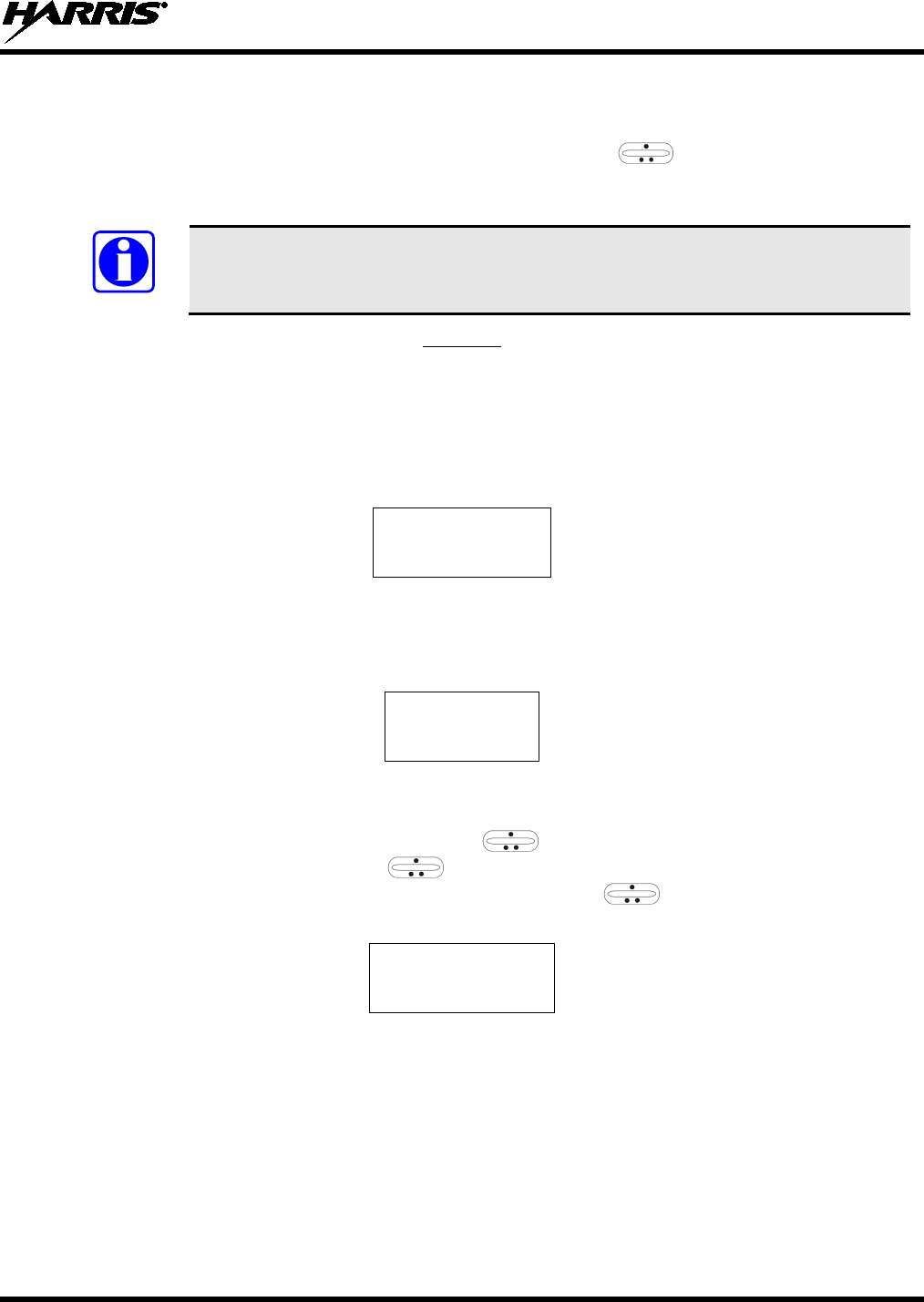
MM-018336-001, Rev. B
29
4.4 SELECTION MODE RULES
Many control head operations require selection from a list such as system, group or phone number. This
selection process is handled in the same manner for all lists. The ramp control, MENU button,
0 - 9, *, # keys, and the CLR button are used during the selection process. The following example
systems list is used to explain the process:
NOTE
The hookswitch functions the same as the CLR button in individual call, phone call,
and menu modes.
SYSTEM
1 NORTH
2
SOUTH
3
EAST
4 WEST
After entering a selection mode, the following generic display format will appear:
X X X X X X X X
Y Y Y = Z Z Z
Line 1 shows the currently selected item name (XXXXXXXX) from the list. Line 2 indicates the list
(YYY) that the selection is to be made from and the number of the selected item (ZZZ) within the list. (In
some cases the information on lines 1 and 2 will be exchanged.) Enter the system selection mode by
pressing the SYS key. If SYSTEM 2 is the current selection, the display appears as follows:
S O U T H
S Y S = 2
Line 1 contains the current system name, SOUTH; and line 2, SYS = 2, indicates that selection is from
the system list and it is the second system within the list.
A new system from the list is selected by using the ramp control or by directly entering the system
number with the numeric keys. The ramp control scrolls through the list in increasing and
decreasing order. In the previous example, pressing up with the ramp control selects the EAST
system as shown in the next display.
E A S T
S Y S = 3
The radio can be programmed to wrap around from one end of a list to the other end, or to stop at each
end.
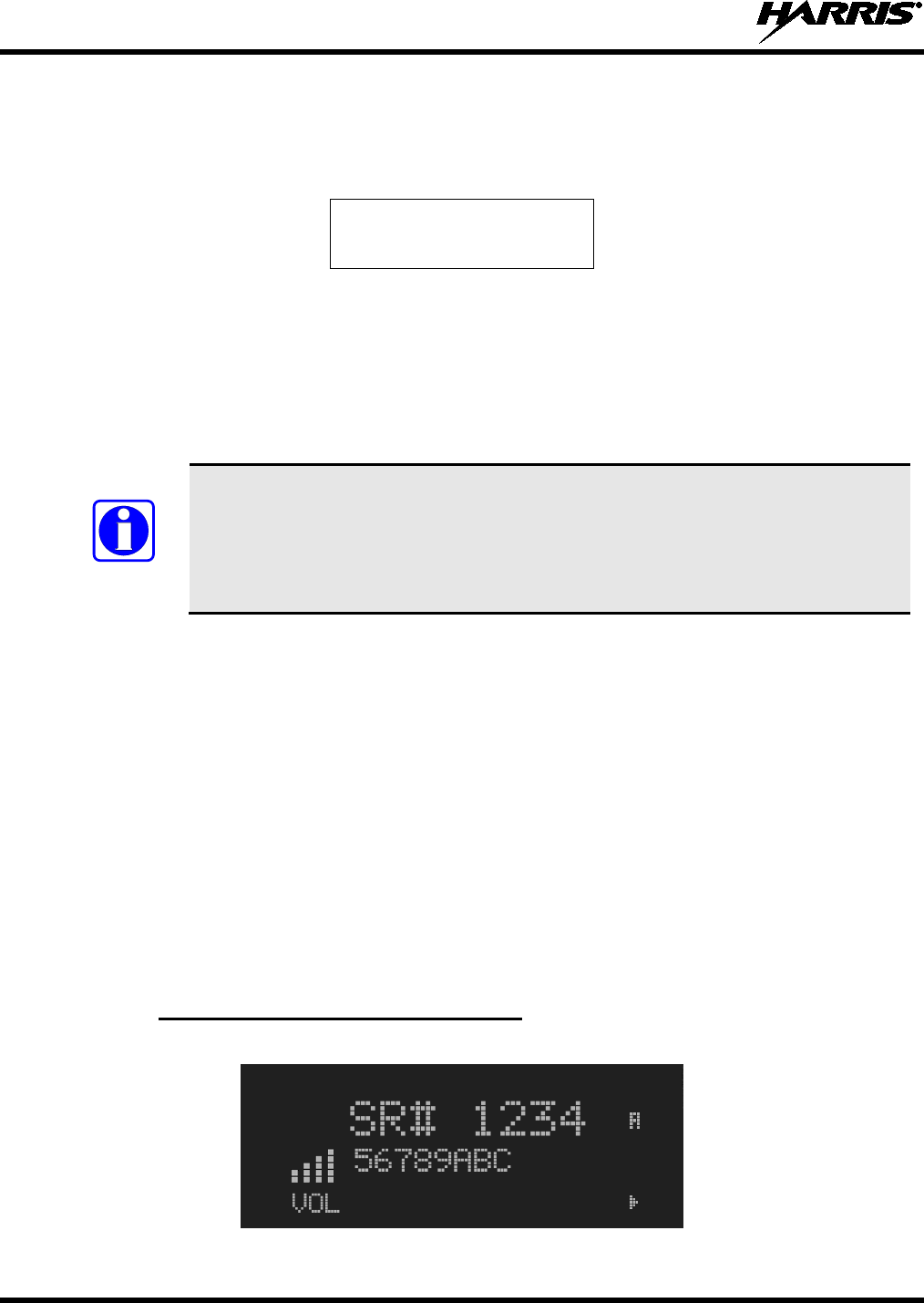
MM-018336-001, Rev. B
30
4.5 DIRECT ACCESS
To directly access a selection, enter the corresponding number (e.g., 4) and then press the MENU button
to activate the selection. The entered number is displayed on line 2 as shown below. Line 1 shows the
current list being used for selection.
S E L S Y S
4
If a mistake is made while entering the number, press the OPT button to backspace once and correct the
entry. If an invalid number is entered, a short low-pitched tone sounds when the MENU button is pressed.
To exit the selection mode, press the CLR button or wait for the time-out. If the selection mode is cleared
while an entry is pending (i.e., numbers are entered on line 2, but the MENU button has not been
pressed), the entry on line 2 will be disregarded and the previous selection will remain active. If the time-
out activates while an entry is pending, the entry on line 2 will be selected if it is within the valid range; if
it is out of range, the entry on line 2 will be disregarded and the previous selection will remain active.
NOTE
While selecting a system or group, the radio continues to receive calls normally and
continues scanning, if it is enabled. If a call is received during the selection mode
process the radio returns
to the normal receive mode display. Continuing with the
selection process returns the display to the same point in the selection process if the
selection mode time out has not yet expired. Any press of the PTT button during the
selection mode process initiates transmission and exits the selection mode.
4.6 FEATURE ENCRYPTION DISPLAY
Feature Encryption Display is available through the menu function and, if programmed, appears in the
menu as “FEATURES.” This data indicates current features programmed into the radio as well as
information required to add features to the radio.
Once the feature has been accessed, all normal menu functions work. The user can scroll up or down
through all of the entries.
Feature Encryption Display provides the ability to view, in the order displayed, the following:
• Serial number ROM data - serial number of the ROM
• Feature encryption data stream - used to enable features
• Number Fields - defines limits
• Features enabled - displays bit fields of enabled features
4.6.1 ROM Serial Number (12 Hex Digits)
Example:
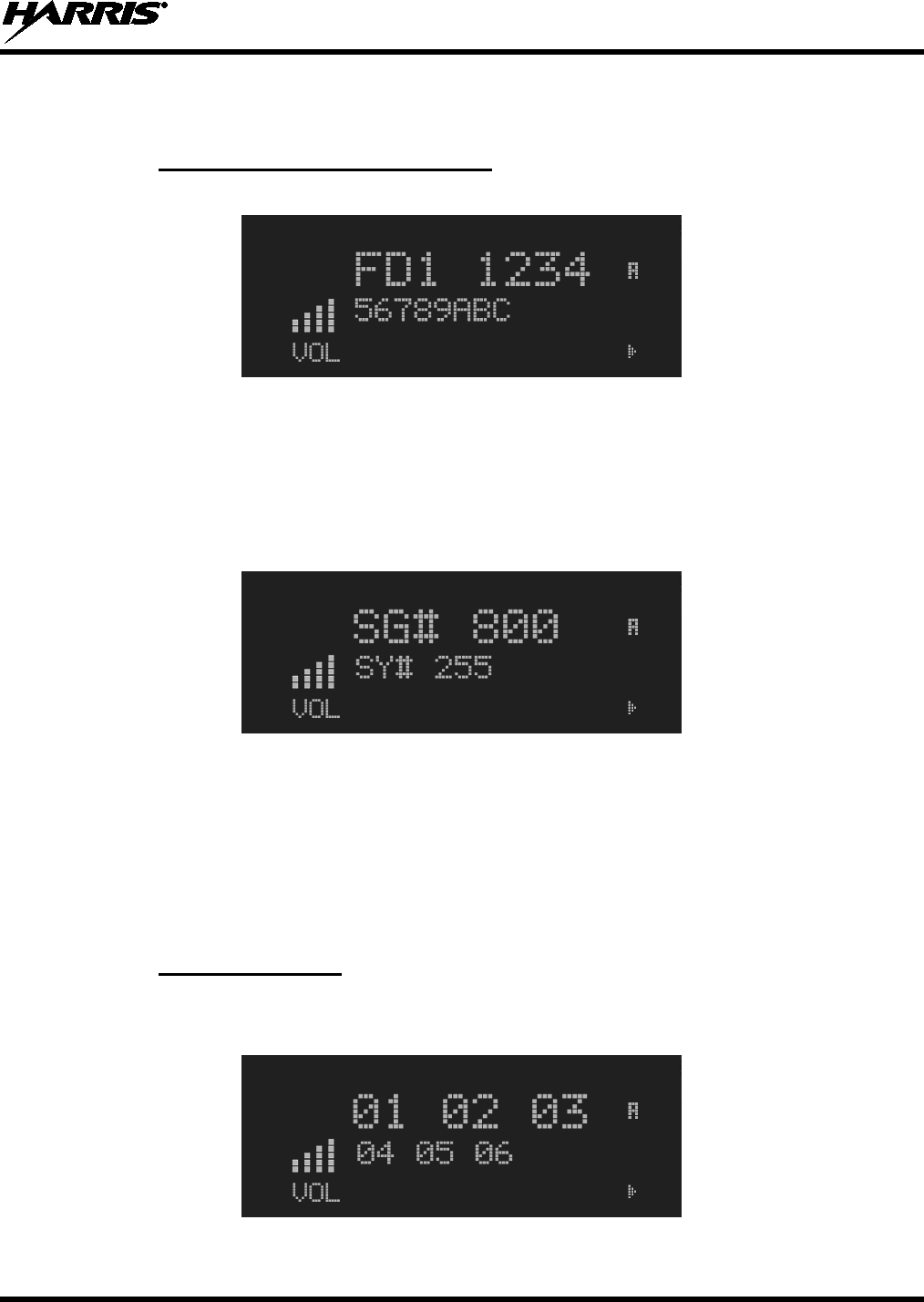
MM-018336-001, Rev. B
31
The ROM serial number must be reported to Harris Corporation before a new feature can be enabled. The
number shown here is an example only.
4.6.2 Feature Encryption Data Stream
Example:
These data streams define the features the user has enabled in his radio and are required by Harris to
enable other features. The data streams shown here are for example only. Note: There are three displays:
FD1, FD2, and FD3. All three are required.
Number Fields
Example:
These number fields show the set limits of the of the user's radio as:
• SG# XXX - Maximum number of system/groups combination available
• SY# XXX - Maximum trunked system limit
The user must know the limits of the radio before attempting to enable other features. The numbers shown
here are for example only.
4.6.3 Features Enabled
These numbers indicate which features are enabled.
Example:
Table 4-2 lists standard and optional features available for the VRS7000.
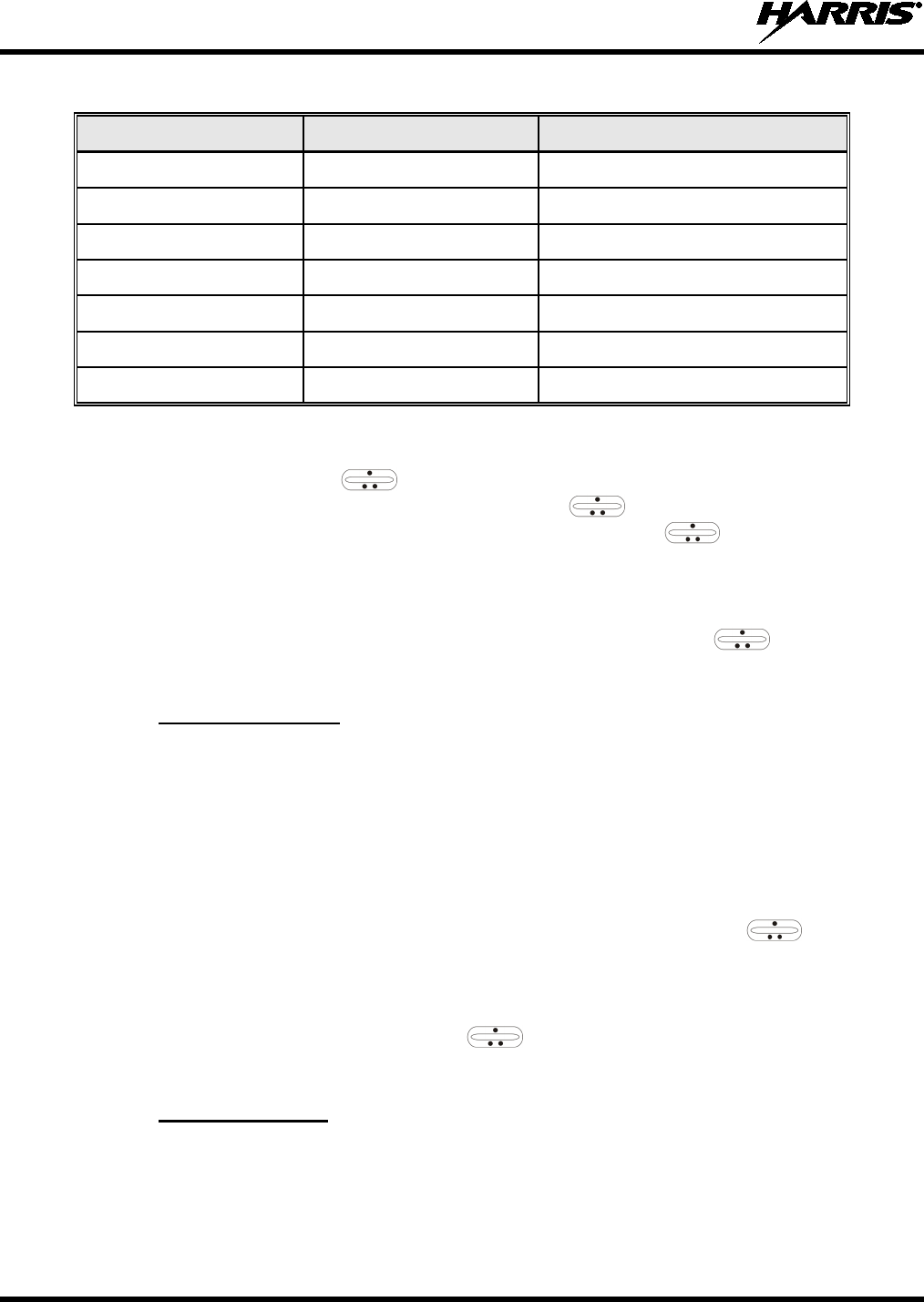
MM-018336-001, Rev. B
32
Table 4-2: Feature Numbers (Standard and Optional)
FEATURE NUMBER FEATURE STANDARD OR OPTIONAL
04 Group Scan Standard
08 Emergency Standard
15 AES Encryption Optional
17 Status/Message Optional
23 Narrowband Standard
32 FIPS-140-2 Encryption Optional
38 Radio TextLink Optional
4.7 SYSTEM/GROUP SELECTION
The System/Group knob and the ramp control are programmable for maximum flexibility. If the
System/Group knob is assigned to select groups, then the ramp control is assigned to select
systems. If the System/Group knob is assigned to select systems, then the ramp control is assigned
to select groups. System and group selection is the primary function for these two controls.
Either systems or groups can also be selected by entering the select mode and following the selection
mode rules described earlier. The system select or group select modes are entered by pressing either the
SYS key or GRP key respectively, from the standard receive mode. Using the ramp control after
entering a particular selection mode in this manner is the secondary function of these keys.
4.7.1 System Selection
Several methods, some of which depend on programming, can be used to select a new system. These
procedures are presumed to be starting from the normal receive display.
METHOD 1: If system selection is programmed to the System/Group
knob, select a system by turning
the System/Group
knob to the desired system position. The display registers the new
system name on line 1. If the wrap option is OFF and the knob is moved to a position
greater than the number of programmed systems, the highest programmed system will
remain selected.
METHOD 2: If system selection is programmed as the primary function of the ramp control
,
select a system by pressing up or down to scroll through the system list. The display
registers the new system name on line 1.
METHOD 3: Press the SYS key to enter
the system select mode and follow the selection mode rules
presented on page 29. Use the ramp control to scroll through
the programmed
systems.
4.7.2 Group Selection
Several methods, some of which depend on programming, can be used to select a new group. These
procedures assume starting from the normal receive display.

MM-018336-001, Rev. B
33
METHOD 1: If group selection is programmed to the System/Group
knob, select a group by turning
the System/Group knob to the desired group. The display registers
the new group
name on line 2. If the wrap option is OFF and the knob is moved to a position greater
than the number of programmed groups, the highest programmed group will remain
selected.
METHOD 2: If group selection is programmed as the primary function of the
ramp control,
select a group by pressing up or down, to scroll through the group list. The display
registers the new group name on line 2.
METHOD 3: Press the GRP key
to enter the group select mode and follow the selection mode rules
presented on page 29. Use the ramp control to scroll through
programmed
groups.
4.8 LAST SYSTEM/GROUP RECALL
The last system/group recall programmable feature allows the user to recall the last selected system/group
after an emergency or home function, or system/group key selection function. For example, if the Home
button (pre-programmed) is pressed, the radio will go to the designated home system/group. If the Home
button is pressed again, the radio returns to the previous system/group. At this time, the user can toggle
between the home system/group and the previous system/group.
4.9 DIGITAL VOICE OPERATION
4.9.1 Receiving an Encrypted Call
When receiving, the radio automatically switches between clear or private operation. If the transmission
being received is an encrypted transmission, it will be decrypted, the receiver will unsquelch and the
message will be heard in the speaker. The selected group must be programmed for private operation and
the correct cryptographic key must be loaded into the radio for this to occur.
4.9.2 Transmitting an Encrypted Call
1. Select the desired group.
2. Place the radio in private mode by pressing the control head’s OPT button.
If the last state of the radio was private mode, the private mode will be enabled on power up. In
addition, the private mode will be enabled if forced operation has been programmed in the radio
If a group is not programmed for private mode operation, PVT DIS will be displayed if an attempt is
made to enable private transmit mode. It is not possible to operate on this group in private mode.
If the radio is programmed for forced private transmit operation, FRCD PVT will be displayed if an
attempt is made to disable private transmit mode. It is not possible to transmit on this group in clear
mode.
If the radio does not have the correct encryption key loaded, NO KEY # will be displayed and the
call will not be transmitted.
3. Continue with standard transmission procedures. A private mode access tone will be heard when the
PTT button is pressed.
4.9.2.1 Scanned Group Calls
Receiving a scanned group call is the same as receiving a selected group call. During the scan hang time,
if the radio was programmed for auto-select, it will transmit back in the same mode it received the call.
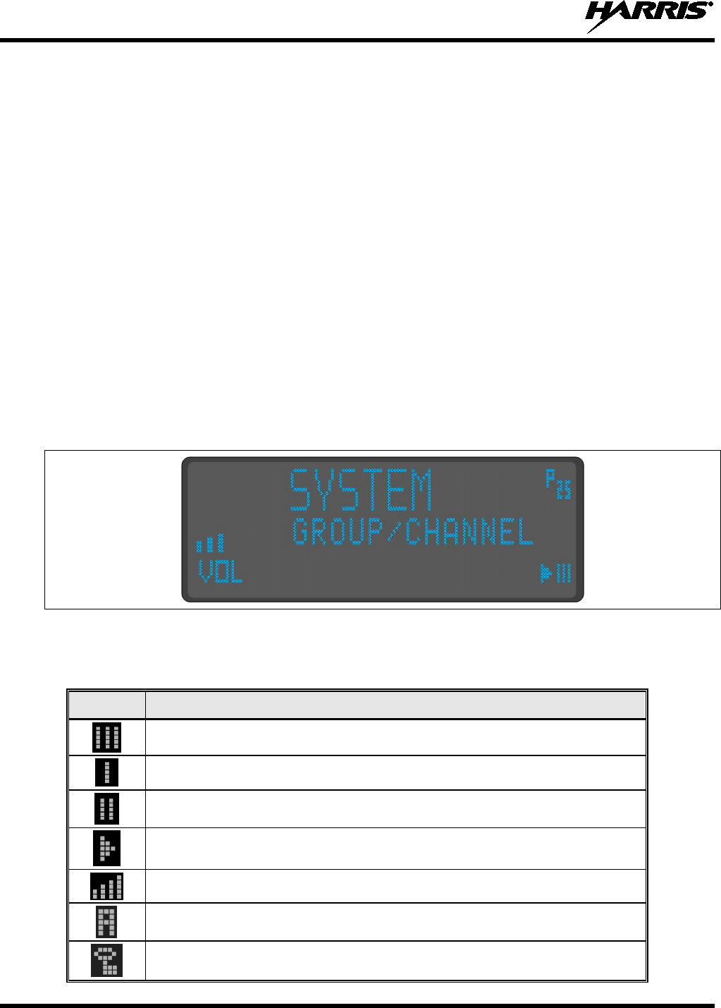
MM-018336-001, Rev. B
34
For example, if a clear group is entered in the scan list, it will only receive clear calls. If the same group
was available in private and entered in the scan list, it can receive clear and private calls, provided auto-
select was programmed in the radio. The user can select transmitting on the scanned or selected group. If
a group is entered in the scan list more than once in different modes (clear, digital, private), only the first
occurrence of the group will be used.
4.10 MACRO KEY OPERATION
Macro key operation permits the user to accomplish a series of keystrokes with a single "macro"
keystroke. Up to ten (10) macro keys can be defined, each capable of executing up to twenty (20)
keystrokes, to any pushbutton input (i.e., keypad keys, buttons, etc.). Each macro key can be pre-
programmed to activate when pressed or when released.
A macro key can also be pre-programmed to change the keystroke sequence the next time the macro key
is activated.
For detail operation and assignment of macro keys, contact your communications supervisor or
administrator.
4.11 RADIO STATUS ICONS
Status icons are indications on the control head’s display that indicate various operating characteristics of
the radio.
Figure 4-2: Typical Display during P25 Trunked Operation
Table 4-3: Radio Status Icons
ICON DESCRIPTION
Indicates selected group is in scan list.
Indicates selected group is programmed as Priority 1 in scan list.
Indicates selected group is programmed as Priority 2 in scan list.
Indicates scan mode enabled.
Volume bars – indicates relative volume of speaker/headset receive audio.
Indicates the current channel is set up as an analog channel.
Indicates receiving or transmitting encrypted calls.

MM-018336-001, Rev. B
35
4.12 MESSAGES
During radio operation, various messages are displayed on either line 1 or line 2. Typical messages
include the respective trunked site’s control channel status information, such as system busy or call
denied, or messages associated with the radio's operation, (i.e. volume adjust). These messages are
described as follows:
Table 4-4: Displayed Messages
MESSAGE NAME DESCRIPTION
QUEUED Call Queued Indicates the system has placed the call in a request queue.
SYS BUSY System Busy Indicates the system is busy, no RF channels are currently available, the queue is
full or an individual call is being attempted to a radio that is currently transmitting.
DENIED Call Denied Indicates the radio is not authorized to operate on the selected system.
CC SCAN Control Channel Scan Indicates the control channel is lost and the radio has entered the Control Channel
Scan mode to search for the control channel.
WA SCAN Wide Area Scan Indicates the control channel is lost and the radio has entered the Wide Area Scan
mode to search for a new system (if enabled through programming).
*RXEMER* Receive Emergency Indicates an emergency call is being received. This message will be flashing on
line 2.
*TXEMER* Transmit Emergency Indicates an emergency call has been transmitted. This message will be flashing
on line 2.
VOL=31 Volume Level Indicates the current volume level. The volume level display ranges from OFF
(silent) to 31 (loudest).
UNKNOWN Caller's ID Not
Received Indicates that an individual call is being received, but the caller's ID was not
received.
TX DATA Transmit Data Indicates the radio is transmitting a data call.
RX DATA Receive Data Indicates the radio is receiving a data call. Displayed on line 2.
DATA OFF Data Off Indicates the radio is in the data disabled state. Displayed on line 1.
DATA ON Data On Indicates the radio has been toggled to the data enable state. Displayed for two
seconds on line 1 when toggled to enable state.
SYSC ON System Scan Features
On Indicates the System Scan features are enabled.
SYSC OFF System Scan Features
Off Indicates the System Scan features are disabled.
PA ON Public Address On Indicates that the public address function of the radio is enabled.
PA OFF Public Address OFF Momentary (2 seconds) - indicates that public address function of the radio was
disabled.
ALRM ON External Alarm
Enabled Indicates that the external alarm function of the radio is enabled.
ALRM OFF External Alarm
Disabled Momentary (2 seconds) - indicates that the external alarm function of the radio
was disabled.
PVT DIS Private Mode Disabled Indicates that private mode is disabled or no encr
yption key has been
programmed for the selected group or special call.
FRCD PVT Forced Private
Operation Indicates that forced private operation has been pre-programmed into radio.
NO KEY # Encryption Key
Missing Flashing - indicates that no encryption k
ey or an incorrect encryption key is
programmed into the radio.
BCKL=1-6 Backlight Indicates the display intensity and keypad backlight level.
GR Group ID Indicates that the call is a group call and is followed by the GID of the caller.

MM-018336-001, Rev. B
36
Table 4-4: Displayed Messages
MESSAGE NAME DESCRIPTION
ID Individual ID Indicates the call is an individual call and the ID number of the caller, example "ID
2725."
WHC=1 Who Has Called
This display indicates the number from the Who Has Called list. Individual calls
received but not responded to are stored in a Who Has Called list. This list is
accessible by pressing the # key and then the INDV key after the Individual call
has timed out or the Clear button is pressed. This display is on line 2 and the LID
of the caller is displayed on the top line. Currently the list is not implemented and
the display will always be WHC=1.
PHONE Phone Call
Displayed when a phone call is received from the site. It is displayed in line 1 of
the display. Line 2 of the display will contain the display *INDV* when line 1
contains this message. The radio interprets a received phone call as an individual
call.
MENU Menu Function Displayed when the menu key is pressed and remains displayed in line 1 until a
menu item is selected.
SYS=1-64 System = 1 - 64 The system number for the current base station of the system displayed in line 1.
It is displayed in line 2 of the display. Press the system key to obtain this display.
GRP=1-64 Group = 1 - 64
The group number of the group displayed in line 2 of display. It is displayed in line
1 of the display. Press the group key to obtain this display. There are up to 48
groups available (i.e. 3 banks of 16). The maximum number of groups
programmed in a radio is determined by the personality.
INDV=1-99 Individual = 1 - 99 Indicates which item in the individual call list is being displayed. It is displayed in
line 2 of the display. The name or ID of the item in the list is displayed in line 1 of
the display.
PHN=1-99 Phone = 1 - 99 Indicates which item in the phone list is being displayed. It is displayed in line 2 of
the display. Line 1 of the display will be the last 3 characters of the list item
contents.
SEL PHN Select Phone After pressing the PHN key, selecting an entry from the phone list by typing the
entry number will display this message on Line 1.
SEL INDV Select Individual ID Displayed on line 1 when an entry from the individual ID list is selected after
pressing the INDV key. The entry is a number between 1 and 32 inclusive.
SYS ALL System All Call Displayed on line 1 to indicate a system all-call has been received.
Ggg-v.vv Code Group
and
Revision Number
This is code group and revision number that is displayed in line 2 when the menu
item “REVISION” menu is selected. The ‘gg’ is the group number of the software.
The first ‘v’ is the hardware version and ‘vv’ is the revision of the software.
*PHONE* Phone Call Displayed when a phone call is initiated. Displayed on line 2 of the display.
NO ENTRY No Entry Indicates that there is no data stored in one of the programmable items in either
the phone list or individual call list. The user programmable items are items 1
through 10 in each list.
INV SYS Invalid System Displayed when the current system is an invalid type.
CHN=1-99 Channel = 1 - 99 Displayed on line 1 of the display. This is a conventional channel index displayed
when the group key is pressed.
FIX LIST Fixed List The Priority scan list is fixed and cannot be changed using the add or delete keys.
FIXED P1 Fixed Priority 1 The Priority 1 scan group is fixed and cannot be changed using the add or delete
keys.
(c) 2009
(example) Radio Software
Copyright Date Displayed in line 2 when “REVISION” menu is selected.
EM Emergency Indicates an emergency has been declared by the LID that follows the display,
“EM.” An example of this is “EM 01201.”
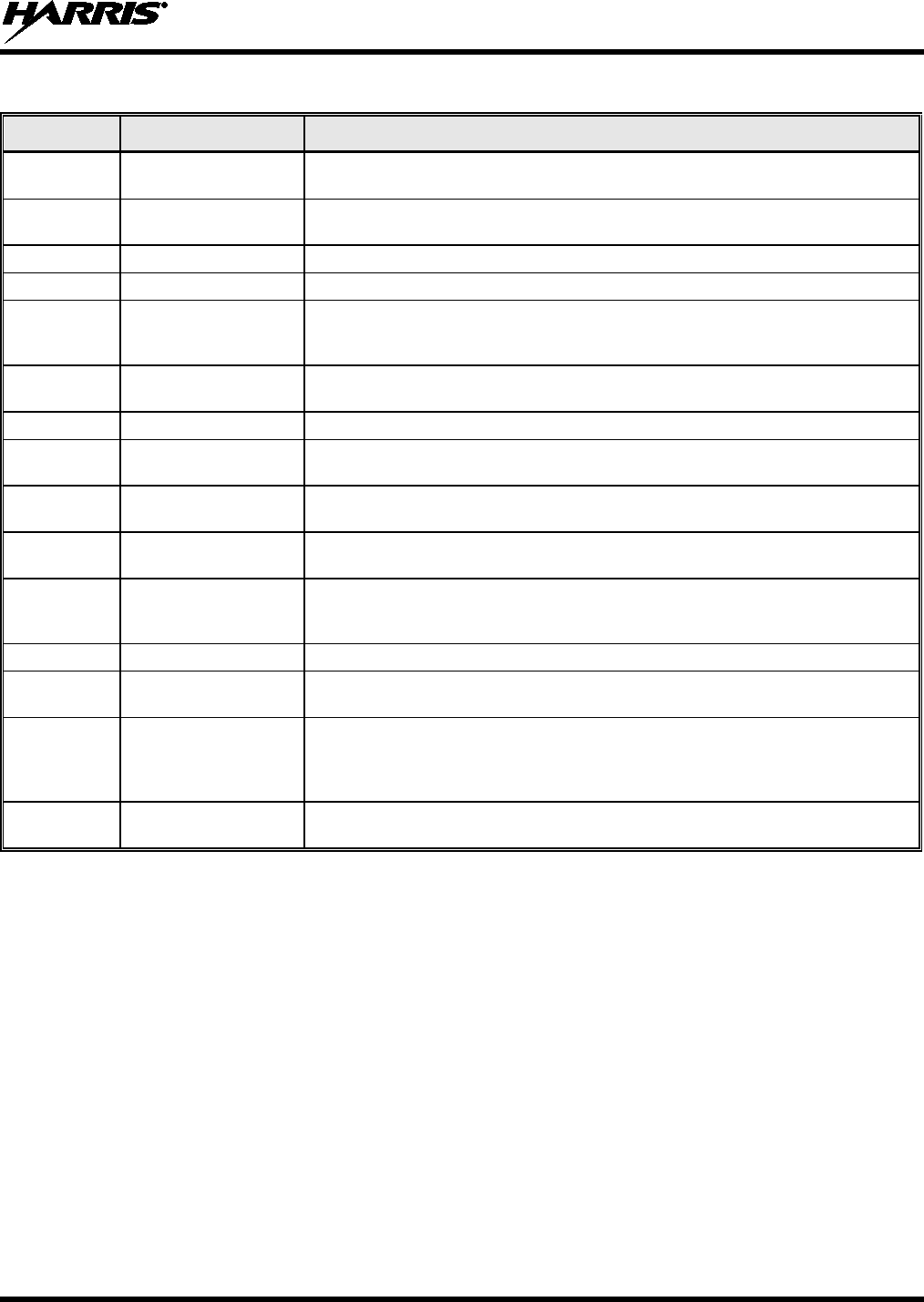
MM-018336-001, Rev. B
37
Table 4-4: Displayed Messages
MESSAGE NAME DESCRIPTION
*INDV* Individual Call Displayed in line 2 of the display when an individual call is in progress (trunked
and T99 modes only).
*GROUP* Group Call Indicates a group call is in progress and is displayed on line 1 of the display
(trunked and T99 modes only).
SPKR ON External Speaker On Displayed when the external speaker is enabled.
SPKR OFF External Speaker Off Displayed when the external speaker is disabled.
BANK=1-8 Bank Number The bank of keys that are going to be loaded when the keyloader loads encryption
keys. This is only valid for radios that support VGS, VGE, or DES encryption. It is
displayed on line 2 of the display when the encryption keyloader is connected.
REGR_0x Dynamic Regroup Indicates which group in the dynamic regroup operation has been enabled, where
“x” is a digit of 1 to 8.
KEY LOAD Key Load Displayed on line 1 of the display when the encryption keyloader is connected.
KEY ZERO Key Zero Displayed on line 2 of the display when the reset and option buttons are pressed
simultaneously for approximately two seconds. The encryption keys are zeroed.
SYS KEY System Key Displayed on line 1 of the display in the display key mode of the menu. It is
followed in the second line with a key number “KEY = <1..7>”.
GRP KEY Group Key Displayed on line 1 of the display in the display key mode of the menu for trunked
systems only. It is followed in the second line with a key number “KEY = <1..7>.”
KEY=1-7 Key Number Displayed on line 2 of the display in the display key mode of the menu for
conventional systems when the “SYS KEY” or “CHN KEY” is displayed in line 1
and for trunked systems when the “SYS KEY” or “GRP KEY” is displayed in line 1.
PRIMARY Primary Keys Displayed on line 1 of the display when the primary keys are enabled.
PRS NAME Personality Name Displayed on line 1 of the display under the revision selection of the menu. The
personality name is displayed on line 2 at the same time.
BND SCAN Band Scan
Only displayed if the P25T system is configured for "EnhancedCC" mode of
operation. When the radio cannot find a Control Channel in either the trunked
frequency set or the list of discovered adjacencies, the radio is able to perform a
full spectrum frequency scan to find a new Control Channel.
REGISTER Registration/Affiliation Displayed when the radio is performing a registration/affiliation on a P25 trunked
radio system (site).

MM-018336-001, Rev. B
38
4.13 ALERT TONES
Via the control head, the radio also provides audible alert tones or “beeps” to indicate the various
operating conditions. These alert tones can be enabled or disabled through programming.
Table 4-5: Alert Tones for P25 Trunked Operation
NAME TONE DESCRIPTION
Call Originate A short mid-pitched tone
Sounds after keying the radio via its Push-To-Talk (PTT)
button. Indicates the radio has been assigned a working
channel. After it sounds, begin speaking into the microphone,
while holding the PTT button depressed.
Autokey A mid-pitched tone
After being placed in a queue or releasing the PTT button
prior to a working channel assignment, the site calls the radio
when a channel becomes available. At this point, the radio
automatically keys the transmitter (autokey) for a short period
to hold the channel. The radio sounds a mid-pitched tone
when it is clear to talk. Immediately press the PTT button to
keep the assigned channel.
Call Queued A high-pitched tone
Sounds after pressing the PTT button indicating the system
has placed the call request in the queue. The receiving unit(s)
also sound(s) the tone to indicate they will receive a call
shortly.
System Busy Three low-pitched tones
Sounds if the radio is keyed when the system is busy, if no
channels are available for sending the message, if the call
queue is full, or if an individual call is being attempted to a
radio that is transmitting.
Call Denied A low-pitched tone Indicates the radio is not authorized on the system that has
been selected.
Carrier Control Timer Five short high-pitched warning
tones followed by a long low-
pitched tone
Sounds if the programmed time for continuous transmission is
exceeded. The transmitter will shut down shortly after the
alert, interrupting communications. Release and re-key the
PTT button to maintain communications. This will reset the
carrier control timer and turn the transmitter back on.
Key Press Alert A short tone Indicates a key has been pressed. A short low-pitched tone
indicates no action was taken because the key is not active in
the current mode.
Page (P25 T Only) Three high-pitched tones In P25 trunked mode, if the receiving radio accepts a page,
both the receiving and transmitting radios emit three high-
pitched tones.
Out of Range One low pitched tone Indicates the radio is in Wide Area Scan.
Radio will
periodically beep when in Wide Area Scan.
4.14 MENU
The menu function accesses features that are not available directly from the keypad. The order and
specific number of menu items available is configurable through programming. Upon radio power up, the
menu item at the beginning of the menu list will always be displayed first. Subsequent access to the menu
function will return the last menu item that was shown in the display. To enter the menu mode, press the
MENU button. The ramp control and CLR are used during the selection process. All of the
selection mode rules previously detailed apply to the menu item selection process with the exception of
direct access. The radio will continue to receive and transmit normally while in the menu function.
A new item is displayed by using the ramp control to scroll through the list in increasing and
decreasing order. Press the MENU button to activate the displayed item.
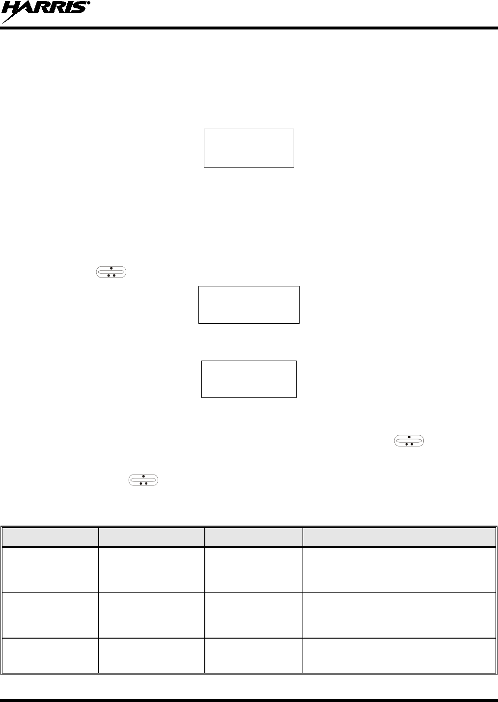
MM-018336-001, Rev. B
39
The radio has two (2) separate pre-configured menus—one is active when the radio is operating on a
trunked system and the other is active when the radio is operating on a conventional system. Each menu
can have up to twenty (20) menu items/selections, but typically less are pre-configured. Because of the
separate menus, trunked menu selections can vary from the conventional menu selections. An operator
cannot add or delete menu items/selections.
After entering the menu selection mode, the following generic display format will appear.
M E N U
Y Y Y Y Y Y Y Y
Line 1 indicates the radio is in the menu selection mode. Line 2 indicates the menu item (YYYYYYYY)
that is to be viewed or changed (some menu items provide radio information and do not have changeable
settings).
An example of the menu item selection process and menu item setting change is detailed below for the
contrast menu item.
1. Press the MENU button to enter the menu mode.
2. Press the ramp control until the display shows:
M E N U
CONTRAST
3. Press the MENU button again. The contrast menu item is activated and the display will be similar to
the following:
CNTRST = X
Y Y Y Y Y Y Y Y
Line 1 shows the active menu item and its current setting (XXX). Line 2 shows the currently selected
system or group name (YYYYYYYY).
4. The menu’s setting shown in the display can now be changed by using the ramp control to
scroll through the list of available settings. Once the desired setting is reached, press the MENU
button to store the value and return to the normal display. For menu items that display radio
information, use to scroll through a list of informational displays. The menu items are listed in
Table 4-6.
Table 4-6: Menu Item Information
FEATURE DISPLAY MENU SETTINGS DESCRIPTION
Display Contrast Level
Adjustment
Menu Item:
CONTRAST
Once selected:
CNTRST=
1, 2, 3, 4, 5, 6, 7, 8 Selects the display’s contrast level for adjust-
ment.
Display and Button
Backlight Brightness
Adjustment
Menu Item:
BCK LGHT
Once selected:
BCKL ADJ
1, 2, 3, 4, 5, 6 Selects the display’s brightness for adjustment.
Adjustment also affects button back
light
brightness.
Radio Revision
Information Menu item:
REVISION
Informational
displays only; no user
selectable settings Selects the information display to view.

MM-018336-001, Rev. B
40
Table 4-6: Menu Item Information
FEATURE DISPLAY MENU SETTINGS DESCRIPTION
Radio Transmit
Power Level
Menu Item:
TX POWER
Once selected:
LOW PWR or
HIGH PWR
Low or High
Transmitter Power
Level
Used to switch the radio’s transmitter power
level between the low and high power settings.
Key Lock
Menu Item:
KEY LOCK
Once selected:
LOCKED or
UNLOCKED
Unlocked or Unlocked
Used to lock the control head’s keypad. To un-
lock, press the MENU and CLR
(Clear) buttons
simultaneously. See Section 4.3 on page 28
for
additional information.
Phone Call
Menu item:
PHN CALL
Once selected: See
Section 4.21 on page 48
(Accesses the
phone call list) Allows access to the
Telephone Interconnect
Call feature. See Section 4.21 on page 48.
Individual Call
Menu Item:
IND CALL
Once Selected: See
Section 4.20 on page 47
(Accesses the
individual call list) Allows access to the Individual Call feature.
See
Section 4.20 on page 47.
External Alarm
Menu Item:
EXTALARM
Once Selected:
EXTALARM
ON, OFF
EXTALARM replaces the system name on the
display as long as the external alarm feature is
enabled.
Public
Address
Menu item:
PUB ADDR
Once selected:
PA ON or
PA OFF
ON, OFF Toggles the Public Address (PA) feature on
and
off.
Usage requires an external PA
speaker/horn.
External Speaker
Menu item:
EXT SPKR
Once selected:
SPKR ON or
SPKR OFF
ON, OFF Toggles the external speaker on and off
. Usage
requires an external speaker. Affects th
e path of
receive audio only.
Encryption Key
Loading
Menu item:
KEYLOAD
Once selected:
KEY LOAD BANK = N
Up to 8 banks
of 7 keys Enables the radio to accept the loading of en-
cryption keys.
Display Current
Encryption Key(s)
Menu item:
DISP KEY
Once selected:
SYS KEY, GRP KEY or
CHN KEY and KEY = N
(current key) Displays current encryption key number.
Scan Menu item:
SCAN ON, OFF Toggles scan function on and off.
Private Mode
Menu Item:
PRIVATE
Once selected:
PVT or key light.
ON, OFF Toggles private function on and off.
Scan Add
Menu item:
SCAN ADD
Once selected: Proper
scan icon displayed.
S, 2 or 1 Adds group to scan list.

MM-018336-001, Rev. B
41
Table 4-6: Menu Item Information
FEATURE DISPLAY MENU SETTINGS DESCRIPTION
Scan Delete
Menu item:
SCAN DEL
Once selected: Scan icon
goes out.
(none) Deletes group from scan list.
Scan Add/Delete
Menu item:
SCAN A/D
When selected: Toggles
through scan selections
Toggle sequence
S, 2, 1, S, ...
Changes present group to next scan choice in
scan list.
Home Group Selection
Menu item:
HOME
Once selected: Home
group displayed.
(Programmed groups) Changes to the group defined for the
Home
function.
System Select
Menu item:
SYS SEL
Once selected:
SYS = n
1 to 64 = (n)umber of
desired system Displays the system selected.
External Alarm #2 Menu item:
EXTALRM2 ON, OFF Toggles external alarm #2 feature on and off.
System and Group
Selection
Menu item: SYSGRP 1
Menu item: SYSGRP 2
Menu item: SYSGRP 3
Menu item: SYSGRP 4
Menu item: SYSGRP 5
(none) Selects the respective pre-programmed s
ystem
& group/channel.
Mute Menu item:
MUTE ON, OFF Toggles the mute function o
n and off to control
the audio output from the radio.
No Data Menu item:
NO DATA ON, OFF Toggles data feature on and off.
Conventional Priority 1
Scan Menu item:
ECP1SCAN ON, OFF Toggles the conventional priority 1 scan
feature
on and off.
Group Selection
Menu item:
GRP SEL
Once selected:
GRP = n
1 to 64 = (n)umber of
desired group Displays the group selected.
Status Condition
Menu item:
STATUS
Once selected:
ST = n
0 to 9 = (n)umber of
pre-programmed status Transmits the pre-programmed status message.
Message Condition
Menu item:
MESSAGE
Once selected:
MSG = n
0 to 9 = (n)umber of
pre-programmed
messages Transmits the pre-programmed message.
Feature Encryption
Display
Menu Item:
FEATURES
Once selected:
See Feature Encryption
Display section
Informational displays
only; no user selectable
settings
Indicates current features programmed into the
radio as well as certain information required to
add features to the radio.

MM-018336-001, Rev. B
42
Table 4-6: Menu Item Information
FEATURE DISPLAY MENU SETTINGS DESCRIPTION
System Scan
Menu Item:
SYS SCAN
Once selected:
SYSC ON or SYSC OFF
ON, OFF Toggles
System Scan features like ProScan on
and off.
Page
Menu Item:
PAGE
Once selected:
(List of stored individual
callers)
(I-Call list) The Page feature sends a ping-
type message
over the radio system to a selected radio.
See
Section 4.24 on page 51 for details.
Squelch Control
Menu Item:
SQUELCH
Once selected:
SQLCH = n
SQLCH=1 to
SQLCH=16
Use to adjust receiver squelch level. F
or analog
conventional and P25 conven
tional systems
only.
ProFile
Menu Item:
PROFILE
Once selected:
PROF OFF or
PROF ON
ON, OFF
The ProFile feature sends radio personality
information "over-the-air"
(i.e., via a radio
frequency channel). For
radio network
administration personnel use only.
Radio Programming Menu Item:
PROGRAM — Enables radio programming mode. For
radio
network administration personnel use only.
Reverse Warm Start
Segment Menu Item:
RWSS —
This Over-the-Air-Rekeying (OTAR)
related
feature can be used to manually request new
encryption key information (TEKs a
nd KEKs)
from the radio system.
Normally only used by
radio network administration personnel.
Service-Related
Information Menu Item:
FCC MENU — Displays radio service-
related information. For
radio network administration personnel use only.
4.15 RECEIVING A CALL
1. Turn the radio on by rotating the Power On/Off/Volume control knob clockwise out of its detent
position. A short alert signal (if enabled through programming) indicates the radio is ready to use.
2. The display shows the last selected or the power up (depending on programming) system and group
names. If the radio is unable to obtain a control channel, line 2 shows CC SCAN.
3. Adjust the Power On/Off/Volume control knob to the desired volume level.
4. Select the desired system and group. The display indicates the current system and group names.
5. The radio is now ready to receive calls.
6. When the radio receives a group call, it unmutes on the assigned working channel and the BSY
indicator comes on. Line 1 shows GR followed by the logical ID number (if received) of the unit
sending the message, or the associated name if the ID number is found in the individual call list.
4.16 SENDING A CALL
1. Turn the radio on and set the Power On/Off/Volume control knob to the desired volume level. Select
the desired system and group.
2. Press and hold the PTT button. The radio will display the system and group names and perform the
necessary signaling required to obtain a communication channel.

MM-018336-001, Rev. B
43
3. When the working channel is assigned, TX and BSY indicators are turned on and a short beep is
sounded indicating communication can begin.
NOTE
If two or more tones, or a high-pitched tone is heard, the system may be busy and the
call request has been placed in queue or the request has been denied for some reason.
Refer to the Section 4.13 for more details.
4. Hold the microphone approximately 1 ½ inches from the mouth and speak in a normal voice.
5. Release the PTT button when the transmission is complete and listen for a reply.
4.17 EMERGENCY OPERATION
The radio's ability to declare an emergency, clear an emergency, remain locked on an emergency and
group, and the emergency audio and display freeze can each be enabled or disabled through
programming. When an emergency is declared, scanning will stop and will restart only after the
emergency has been cleared.
4.17.1 Receive an Emergency Call
When receiving an emergency call from the selected group and system, an alert beep is heard and the
BSY indicator lights. The message *RXEMER* flashes in the display on line 2 until the emergency
condition is cleared. Follow standard emergency procedures.
4.17.2 Declare an Emergency
To send an emergency call to the selected system and group (or on an optionally pre-programmed
emergency group), proceed as follows:
1. Press and hold the red Emergency/Home button for approximately one second. (This time is
programmable and therefore could be longer or shorter. Check with the system administrator.) The
radio will transmit an emergency call request with the radio ID until an emergency channel
assignment is received.
2. When the working channel assignment is received, the radio sounds a single beep (Autokey alert
tone) indicating it is ready for voice transmission. *TXEMER* flashes on line 2 in the display until
the emergency is cleared.
3. Press PTT and speak into the microphone in a normal voice.
4. Release PTT when the transmission is complete and listen for a reply.
5. The emergency can be cleared by pressing and holding the CLR button followed by pressing the red
Emergency/Home button then releasing both buttons.
4.18 SYSTEM SCAN OPERATION
The radio can be programmed with the following system scan features. These features are automatically
enabled upon radio power up. A key or menu option is also defined to allow the system scan features to
be toggled during radio operation. This is covered in the Menu Selection and Pre-Programmed Keypad
Key sections. The system scan state will be maintained through system changes but will default to on at
power up.
4.18.1 Wide Area System Scan
The mobile radio can be programmed for wide area system scan operation. Upon the loss of the currently
selected system’s control channel, radios can be programmed to automatically scan the control channels

MM-018336-001, Rev. B
44
of other systems. If a new control channel is found, the radio will switch to the new system and sound an
alert tone.
4.18.2 ProScan™
The radio can be programmed for ProScan™ system scan operation for multi-site applications depending
on the version of radio flash code. ProScan provides the radio with the ability to select a new system for
the radio to communicate on, when the selected system drops below a predefined level. This is
accomplished by enabling each radio to analyze the signal quality of its current control channel and
compare it with the signal quality of the control channel for each site in its adjacency scan list. The signal
quality metric used for the ProScan algorithm is based on a combination of both Received Signal Strength
Indicator [RSSI] and Control Channel Verification [CCV] measurements. When the selected system’s
signal quality level degrades below a pre-programmed level, the radio will begin to look for a better
control channel. Once a control channel that exceeds the pre-programmed settings is found, the radio will
change to the new system and emit a tone. If the control channel is completely lost, the radio enters Wide
Area System Scanning and searches the programmed adjacent systems until a suitable control channel is
found.
4.18.3 Priority System Scan
The radio can also be programmed for Priority System Scan. (To ensure that this feature operates
correctly, the control channel of the priority system must be located on channel one unless you are using
the ProScan algorithm.) The priority system is the desired or preferred system. While receiving the
control channel of the selected system, the radio will periodically leave the selected system and search for
the control channel of the priority system at a programmable rate. The programmable rate is defined by
the value in the Priority Scan Time control, (unless the ProScan algorithm is enabled as explained below).
This priority scan timer is reset each time the PTT button is pressed or when a call is received. If the
priority system control channel is found, or meets the predefined ProScan criteria, the radio will
automatically switch to the priority system.
4.18.4 When Wide Area System Scan Is Enabled
If the radio cannot find the control channel of the selected system and begins Wide Area System Scan
(WA Scan), the radio will only scan for the priority system control channel if the priority system is in the
WA Scan list.
4.18.5 When ProScan Is Enabled
The radio monitors the priority system and will switch to the priority system if the priority system meets
the criteria defined in the “ProScan Options” dialog box. If ProScan is enabled, the rate at which the radio
will scan for the priority system is defined by the System Sample Time control.
4.18.6 Menu Selection
Press the MENU button and then use the ramp control to scroll through the selections until SYS
SCAN is displayed. Then press the MENU button to toggle the System Scan state. The SYSC ON or
SYSC OFF display message is displayed for two seconds to show the new state.
4.18.7 Pre-Programmed Keypad Key
Press the pre-programmed key and the SYSC ON or SYSC OFF display message is displayed for two
seconds to show the new state.

MM-018336-001, Rev. B
45
4.19 GROUP SCAN OPERATION
Only groups that are part of the radio's scan list will be scanned. Groups are added to the scan list on a per
system basis through programming, the radio keypad, or both, dependent upon programming. This scan
list can be changed by the user from the keypad unless programmed otherwise. Each system's group scan
list is retained in memory when the radio is turned off. The radio can also be programmed to provide
trunked priority group scan capability.
The following is a description of programmable scan features that should be helpful in understanding the
group scan operation of the radio:
Scan Hang Time - the delay time the radio waits before resuming scan after the push-to-talk is released
or after the carrier has dropped a channel.
TX Select - the group the radio will transmit on while scanning. The radio is programmed to transmit on
either the scanned group or the selected group.
Scan List (privileges) - this feature allows or prohibits scan list changes by the user.
P1 Programming - priority group programming is accomplished by one (and only one) of three methods:
• From the keypad, where the priority programming is not fixed and does not follow the selected
channel,
• Priority 1 group programming follows the selected channel, or
• Priority 1 group programming is fixed during radio programming and cannot be changed by the user.
P1 Always Scan - determines if the Priority 1 group will always be scanned, regardless of the scan state
set by the user.
4.19.1 Add Groups to a Scan List
1. With scan operation turned off, select the desired group to add to the selected Trunked system group
scan list.
2. Press (+) or (-) with to display the current priority status of the group on line 1 for a time-out
period.
3. While the status is displayed, press (+) with to add the group to the scan list. is displayed.
4. Press (+) with a second time to set the group to Priority 2. is displayed.
5. Press (+) with a third time to set the group to Priority 1. is displayed in column 1, line 1.
The priority level selection sequence only advances the group to the next higher priority level and
stops at priority level 1. To select a lower priority level, the group must be deleted from the scan list
and then added back to the scan list. Each new group added to the scan list starts at the lowest
priority. If the Priority 1 and Priority 2 groups are already set and a new group is assigned as Priority
1 or Priority 2, the previously assigned group will change to non-priority scanning.
4.19.2 Delete Groups from a Scan List
1. With scan operation turned off, select the desired group to delete from the selected trunked system’s
group scan list.
2. Press (+) or (-) with . The current scan status of the group is displayed for a time-out period.
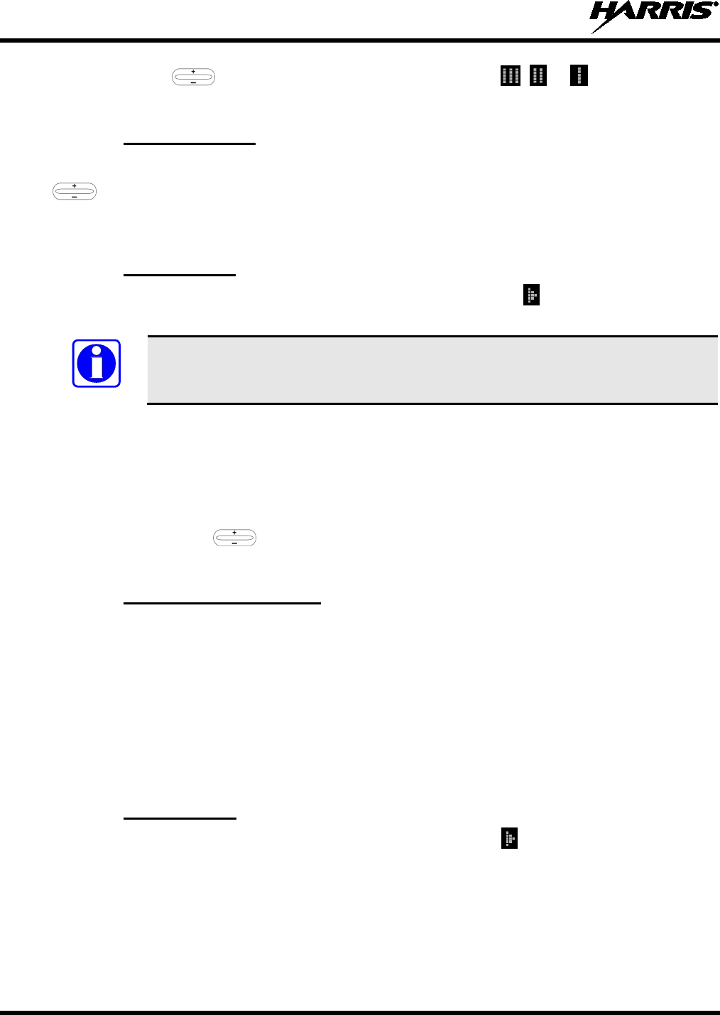
MM-018336-001, Rev. B
46
3. Press (-) with to delete the group from the scan list. The , or icon turns off. Any
group that is not in a trunked system group scan list will show a “blank” when it is selected.
4.19.3 Nuisance Delete
A group can also be deleted from the scan list, if it is not the currently selected group by pressing (-) with
during scan operation while the radio is displaying the unwanted group. The group will be deleted
from the system's group scan list in the same manner as if done using the steps above. Deletions
performed in this manner will not remain deleted if the radio is turned off and then back on.
4.19.4 Turn Scan On
1. Toggle scan operation on by pressing the SCAN button. Scan icon turns on when the radio is
scanning.
NOTE
The SCAN button light blinks when temporarily disabled. Scanning will stop while
microphone is off-hook if the hookswitch feature is enabled through programming.
2. When a group on the scan list receives a channel assignment, the radio unmutes on the assigned
channel, the BSY indicator comes on and the received scan group is displayed.
• The radio will continue scanning if a new group is selected when scan is on.
• Pressing the PTT button when scan is on will cause the radio to transmit on the displayed group
or on the currently selected group depending on programming.
• Pressing up with when scan is on will cause the radio to recall the scanned group that was
last received. This group is recalled for a period equal to the scan hang time.
4.19.5 Priority Group Scanning
When scan is enabled and the Priority 1 and Priority 2 groups have been identified, the radio will listen to
calls on those groups and the selected group. While receiving a scanned group call, the radio will continue
to monitor the selected Priority 1 and Priority 2 groups and will drop the call if the selected group or other
higher priority call becomes active. During a Priority 2 call, the radio will continue to monitor for a
Priority 1 group call.
The radio will monitor for Agency and Fleet calls that correspond to the Agency and Fleet associated with
the Priority 1 and Priority 2 groups. Priority Agency and Fleet calls will be indicated by displaying
AGENCY or FLEET on the System line of the display and associated Priority 1 or 2 group on the Group
line of the display.
4.19.6 Turn Scan Off
Toggle scan operation off by pressing the SCAN button. Scan icon turns off (disappears from the
display) when the radio is not scanning. After turning scan off, the radio resumes operation on the
selected group.
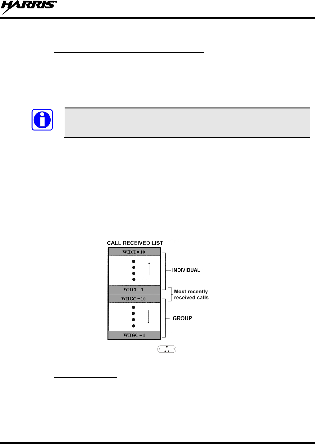
MM-018336-001, Rev. B
47
4.20 INDIVIDUAL CALLS
4.20.1 Receive and Respond to an Individual Call
When the radio receives an individual call (a call directed only to the user's radio), it unmutes on the
assigned working channel and turns on the BSY indicator. Line 1 shows “ID” followed by the logical ID
number of the radio sending the message, or the associated name if the ID number is found in the
individual call list. Also, *INDV* is displayed in line 2 of the display. The radio can be programmed to
ring when an individual call is received. If enabled, the ring begins five (5) seconds after the caller
unkeys. It will continue until the PTT button, the CLR button, or the IND key is pressed.
NOTE
The hookswitch functions the same as CLR button in individual call, phone call, and
menu modes.
If a response is made to the call prior to the programmed call-back time-out, the call will automatically be
directed to the originating unit. If a response is not made before the call-back time-out, the radio will
return to normal receive mode, but * WHC * will be displayed. If the caller's ID is not received,
UNKNOWN will display for the duration of the call and there will be no call-back hang time.
To respond after the call-back time-out, press the IND key. The radio's display will show the callers ID on
the first line and WHCI=1 on the second line. Pressing the PTT button at this point will initiate an
individual call back to the original caller. (If the last call was a group call, the display will show
WHCG=1. Pressing the PTT button will place the call as an individual call.)
The radio stores the IDs of the last 10 callers in the Calls Received List as shown. Individual calls are
stored in the top half of the list (1-10) and group calls are stored in the bottom half of the list (1-10). The
most recent call is stored in position 1, the second most recent call is stored in position 2, etc.
To access the list, press the IND key twice. Use to scroll through the list. Press the MENU button
to display the time elapsed since the call was received.
4.20.2 Call Storage Lists
There are two lists available for call storage in the radio: The calls received list (1 to 10) and the
personality list (1 to 99 as defined by the user). When the individual call mode is entered by pressing the
IND key, the calls received list is available. The user can toggle to the personality list by selecting any
key other than DIS or toggle between the two lists by pressing the IND key. If wrap is enabled, the calls
received list wraps on itself and not into the other list.
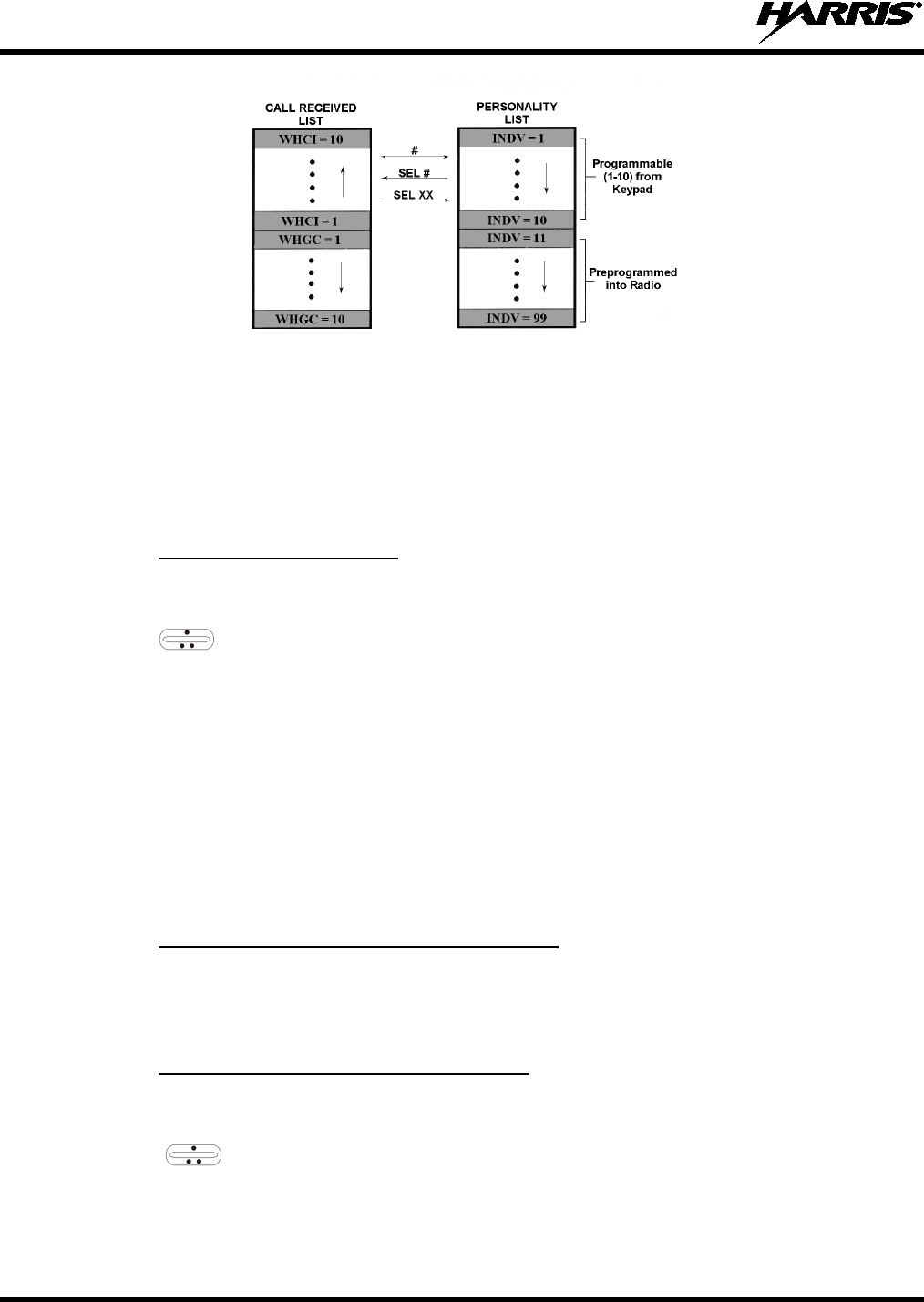
MM-018336-001, Rev. B
48
The saved call list shows all ten storage locations. If no calls have been received, the saved call list will be
empty and the pre-stored list will be available upon entering the individual call mode.
When in the saved call list, pressing the MENU button toggles the time stamp on and off. The time stamp
indicates how long ago the call was received. The display indicates this information as HH:MM:SS where
HH = hours, MM = minutes and SS = seconds.
When in the pre-stored list, pressing the MENU button toggles the Logical IDentification (LID) on and off.
4.20.3 Send an Individual Call
The following procedures describe how to initiate and complete an individual call.
1. To select a previously stored individual, select the I-Call mode from the menu or press IND followed
by the ramp control to scroll through the list of stored individuals. The selection mode rules
apply. While in the individual call list, the menu key will toggle the display between the call name
and the unit ID number. If the individual is not stored in this list but the individual’s unit ID is known,
it can be entered directly from the keypad.
2. Press the PTT button; the radio performs the necessary signaling to obtain a communication channel.
When the signaling is complete and the radio is clear to transmit, TX indicator turns on and the
channel access tone sounds. Line 1 shows the called individual's name if found in the list of stored
individuals or ID followed by the logical ID number of the unit being called. The message *INDV*
displays on line 2. Proceed with the message.
4.21 TELEPHONE INTERCONNECT CALLS
4.21.1 Receive a Telephone Interconnect Call
Receiving a telephone interconnect call is identical to receiving an individual call. See the DTMF
Overdial Operation section if access to services requiring "over-dial" is needed. Overdial operations are
available for any special call whether it is an individual call or a telephone interconnect call.
4.21.2 Send a Telephone Interconnect Call
Use the following procedures to initiate and complete a Telephone Interconnect call:
1. To select a previously stored phone number, select phone call mode from the menu, press PHN and
use the ramp control to scroll through the list of stored phone numbers. The selection mode
rules apply. While in the phone call list, the MENU key will toggle the display between the phone
call name and the phone call number. If the phone number is not stored in this list but the phone
number is known, it can be entered directly from the keypad. If necessary, a pause can be entered by
pressing and holding 0-9, (*), or (#) until an underscore appears in the display.
MM-018336-001, Rev. B
49
2. Press and release the PTT button; the radio performs the necessary signaling to obtain a
communication channel. When the signaling is complete and the radio is clear to transmit, TX
indicator turns on and the channel access tone sounds. Line 1 shows the accompanying name if
selected from the list of stored numbers or the phone number if entered directly. The message
*PHONE* is displayed on line 2. The radio then automatically transmits the programmed number
stored in the special call queue.
3. Telephone ringing will be heard. When someone answers the phone, press the PTT button and speak
into the microphone. Release the PTT button to listen to the caller. Unsuccessful interconnect
signaling returns the radio to the normal receive mode and the number remains displayed until the
special call is cleared by pressing the CLR button or the time-out expires or another group or system
is selected.
4. To terminate the call, momentarily press the CLR button.
NOTE
The radio provides half-duplex conversation only. The caller’s message can only be
sent if the PTT button is pressed (the radio is transmitting) and the caller can only be
heard by the person being called when the PTT is released (the radio is receiving).
4.21.3 DTMF Overdial/Conventional Mode Telephone Interconnect
Once the radio has established a connection to the public telephone system, it may be necessary to "over-
dial" more digits to access banking services, answering machines, credit card calls or other types of
systems that require DTMF (Dual-Tone Multi-Frequency) access digits. Overdial operation can also be
used to initiate a telephone interconnect call via DTMF signaling if a dial tone has already been accessed
on the system. This is the method that is used for making a telephone interconnect call while operating in
the conventional mode but will also function in trunked mode if a dial tone is directly accessible.
Telephone numbers and other number sequences for overdialing can be stored in the phone list when
programming the radio or stored by the operator in the first ten phone list entries. These numbers are
accessed by pressing PHN then following the selection mode rules.
The following steps are required to dial these numbers:
1. Follow the procedure in Sending a Telephone Interconnect Call (Trunked Mode Only) to
establish a connection to the telephone system or consult the system administrator for the procedure
to access a dial tone on the trunked or conventional system.
2. Overdial numbers are transmitted using either method as follows:
METHOD 1:
Press and hold PTT while entering the overdial number sequence from the keypad.
This method sends DTMF tones during individual, telephone interconnect,
or
trunked group calls. Anytime the PTT button is pressed and held, the keypad is
enabled for DTMF entry.
METHOD 2: Press PHN
to enter the overdial select/entry mode and follow the selection mode
rules to call up a stored number f
rom the phone list or to directly enter the overdial
digits. Press PTT to send the overdial sequence once. If the number needs to be
transmitted again it must be selected or entered again (this prevents unwanted
numbers from being sent the next time the PTT button is pressed during the call).
This overdial select/entry mode remains active until the call is dropped, cleared, or MENU is pressed. The
overdial select/entry mode can be re-entered if the call is still active by pressing PHN.

MM-018336-001, Rev. B
50
4.21.4 Programmable Entries
Individual call ID numbers, telephone numbers and other number sequences for overdialing are stored in
the special call lists when programming the radio. The first ten entry locations of these lists can be
changed by the radio operator. The keypad is used when adding, changing and storing numbers in these
entry locations.
Use the following procedure to store a number in one of the first ten entries of a special call list:
1. Press IND or PHN to enter the individual call list or the phone call list. The selection mode rules
apply.
2. Scroll through the list using the ramp control until one of the first ten entries is reached. NO
ENTRY is displayed if the location is empty.
3. Enter the desired number. If necessary, a pause can be entered by pressing and holding 0-9, (*), or (#)
until an underscore appears in the display. The individual call list entries will accept up to 5 digits.
The phone call list entries accept a combination of up to 31 digits and pauses.
4. Press and hold MENU until the display changes indicating that the number has been stored.
5. Repeat the steps above if the number stored in an entry location needs to be changed.
4.22 STATUS OPERATION
Status operation is an optional feature that permits the transmission of a pre-programmed status condition
to the P25 trunked radio network.
To send a status condition, press the STS key (key’s backlight lights) then press one of the number keys
(0 through 9) to select the pre-programmed status. If no status has been programmed for the respective
number, NO ENTRY will be displayed and the radio will sound a low tone. A valid selection will permit
the status text to appear in the display for a pre-programmed time. After the time-out expires or the
MENU button has been pressed (the MENU button will override the time-out period), the status is
selected and will be transmitted to the P25 trunked radio network, or stored in the radio memory where it
can be polled by the P25 network at a future time. If the P25 network receives the status properly, when
transmitted or polled by the P25 network, a high-pitched tone sounds and the respective key’s backlight
will remain lit. If the P25 network does not receive the status properly, a low-pitched tone sounds and the
key’s backlight associated with the status will blink.
If an incorrect status was selected or the incorrect number key was pressed, the status can be changed
during the pre-programmed time-out period by pressing another number key. The status selection can also
be cancelled by pressing the CLR button prior to the time-out period.
To view the currently selected status after it has been transmitted, press the STS key. If the status was not
sent successfully to the P25 network, the text associated with the status will flash in the display.
The radio can also be pre-programmed to assign the keypad buttons for ST0 through ST9 to send status
condition. In this configuration the radio status operation will operate as previously described, except the
STS key is not required. The key’s backlight associated with ST0 thru ST9 will light to indicate which
status is selected.
4.23 MESSAGE OPERATION
Message operation is an optional feature that permits the transmission of a pre-programmed message to
the P25 trunked radio network.
To send a message, press the MSG key (key’s backlight lights) and then press one of the number buttons
(0 through 9) to select the pre-programmed message. If no message has been programmed for the

MM-018336-001, Rev. B
51
respective number, the radio will display NO ENTRY and a low-pitched tone sounds. A valid selection
will permit the message to appear in the display for a pre-programmed time. After the time-out expires or
the MENU button has been pressed (the MENU button will override the time-out period), the message is
selected and will be transmitted to the P25 network. If the network receives the message properly when
transmitted, a high pitched tone sounds and the MSG key’s backlight remains lit. If the P25 network does
not receive the message properly, a low-pitched tone sounds and the MSG key’s backlight will blink.
If an incorrect message was selected or the incorrect number button was pressed, the message can be
changed during the pre-programmed time-out period by pressing another number button. The message
selection can also be cancelled by pressing the CLR key prior to the time-out period.
To view the currently selected message after it has been transmitted, press the MSG key and then the
CLR button prior to the time-out period. If the message was not sent successfully to the P25 network, the
text associated with the message will flash in the display.
4.24 PAGE
The Page feature sends a ping-type message over the radio system to a selected radio. It functions similar
to Individual Call feature. To initiate and complete a Page:
1. Press the MENU key and then select the Page menu.
2. Use the ramp control to scroll through the list of stored individual callers. The selection mode
rules apply. While in the individual call list, press the MENU key to toggle the display between the
call name and the unit ID number. The individual caller’s unit ID can also be entered directly from
the keypad.
3. Press the PTT button. The radio then performs the necessary signaling. On the calling radio, line 1
shows the called unit ID’s name if found in the list of stored individuals, or ID followed by the logical
ID number of the unit being called. If the receiving radio receives the Page and responds, both radios
will emit three high-pitched tones. The receiving radio will also display PAGE and the ID of the
calling radio.
5 TECHNICAL ASSISTANCE
Harris Technical Assistance Center (TAC) resources are available to help with overall system operation,
maintenance, upgrades and product support. TAC is the point of contact when answers are needed to
technical questions.
Product specialists, with detailed knowledge of product operation, maintenance and repair provide
technical support via a toll-free (in North America) telephone number. Support is also available through
mail, fax and e-mail.
For more information about technical assistance services, contact your sales representative, or call the
Technical Assistance Center at:
• United States and Canada: 1-800-528-7711 (toll free)
• International: 1-434-385-2400
• Fax: 1-434-455-6712
• E-mail: PSPC_tac@harris.com

MM-018336-001, Rev. B
52
6 KEYPAD REMAPPING
If buttons/keys have been remapped to provide new functions, fill in the following template for future reference.
BUTTON FUNCTION KEY FUNCTION
Emergency 1
Preset A 2
Preset B 3
Preset C 4
Rocker
•
5
Rocker
••
6
Rocker
+
7
Rocker
-
8
MENU 9
OPT/OPTION *
CLR/CLEAR 0
SCAN #

MM-018336-001, Rev. B
53
7 RADIO SETUP
RADIO TYPE:
FREQUENCY BAND:
OPERATOR'S NAME:
EMERGENCY GROUP:
SYSTEM NUMBER SYSTEM NAME TRK/CNV GRP/CHN NUMBER GRP/CHN NAME USE

MM-018336-001, Rev. B
54
SYSTEM NUMBER SYSTEM NAME TRK/CNV GRP/CHN NUMBER GRP/CHN NAME USE

MM-018336-001, Rev. B
55
SYSTEM NUMBER SYSTEM NAME TRK/CNV GRP/CHN NUMBER GRP/CHN NAME USE

MM-018336-001, Rev. B
56
SYSTEM NUMBER SYSTEM NAME TRK/CNV GRP/CHN NUMBER GRP/CHN NAME USE
8 WARRANTY REGISTRATION
Please register this product within ten (10) days of purchase. Registration validates the warranty coverage,
and enables Harris to contact you in case of any safety notifications issued for this product.
Registration can be made on-line at www.pspc.harris.com/CustomerService or by contacting Harris
Warranty Administration at the following:
United States and Canada:
• Phone Number: 1-800-368-3277, Option 4 (toll free)
• Fax Number: 1-434-455-6821
• E-mail: WarrantyClaims@Harris.com
International:
• Phone Number: 1-434-455-6403
• Fax Number: 1-434-455-6676
• E-mail: WarrantyClaims@Harris.com

MM-018336-001, Rev. B
57
WARRANTY
A. Harris Corporation, a Delaware Corporation, through its RF Communications Division (hereinafter
"Seller") warrants to the original purchaser for use (hereinafter "Buyer") that Equipment manufactured
by or for the Seller shall be free from defects in material and workmanship, and shall conform to its
published specifications. With respect to all non-Seller Equipment, Seller gives no warranty, and only
the warranty, if any, given by the manufacturer shall apply. Rechargeable batteries are excluded
from this warranty but are warranted under a separate Rechargeable Battery Warranty (ECR-7048).
B. Seller’s obligations set forth in Paragraph C below shall apply only to failures to meet the above
warranties occurring within the following periods of time from date of sale to the Buyer and are
conditioned on Buyer’s giving written notice to Seller within thirty (30) days of such occurrence:
1. for fuses and non-rechargeable batteries, operable on arrival only.
2. for parts and accessories (except as noted in B.1), ninety (90) days.
3. for P7300, P7200, P7100IP, P5400, P5300, P5200, P5100, P3300, M7300, M7200 (including
V-TAC), M7100IP, M5300 and M3300 radios, two (2) years, effective 10/01/2007.
4. for Unity® XG-100P, three (3) years.
5. for all other equipment of Seller’s manufacture, one (1) year.
C. If any Equipment fails to meet the foregoing warranties, Seller shall correct the failure at its option (i)
by repairing any defective or damaged part or parts thereof, (ii) by making available at Seller’s factory
any necessary repaired or replacement parts, or (iii) by replacing the failed Equipment with equivalent
new or refurbished Equipment. Any repaired or replacement part furnished hereunder shall be
warranted for the remainder of the warranty period of the Equipment in which it is installed. Where
such failure cannot be corrected by Seller’s reasonable efforts, the parties will negotiate an equitable
adjustment in price. Labor to perform warranty service will be provided at no charge during the
warranty period only for the Equipment covered under Paragraph B.3 and B.4. To be eligible for no-
charge labor, service must be performed at Seller’s factory, by an Authorized Service Center (ASC)
or other Servicer approved for these purposes either at its place of business during normal business
hours, for mobile or personal equipment, or at the Buyer’s location, for fixed location equipment.
Service on fixed location equipment more than thirty (30) miles from the Service Center or other
approved Servicer’s place of business will include a charge for transportation.
D. Seller’s obligations under Paragraph C shall not apply to any Equipment, or part thereof, which (i) has
been modified or otherwise altered other than pursuant to Seller’s written instructions or written
approval or, (ii) is normally consumed in operation or, (iii) has a normal life inherently shorter than the
warranty periods specified in Paragraph B, or (iv) is not properly stored, installed, used, maintained or
repaired, or, (v) has been subjected to any other kind of misuse or detrimental exposure, or has been
involved in an accident.
E. The preceding paragraphs set forth the exclusive remedies for claims based upon defects in or
nonconformity of the Equipment, whether the claim is in contract, warranty, tort (including
negligence), strict liability or otherwise, and however instituted. Upon the expiration of the warranty
period, all such liability shall terminate. The foregoing warranties are exclusive and in lieu of all other
warranties, whether oral, written, expressed, implied or statutory. NO IMPLIED OR STATUTORY
WARRANTIES OF MERCHANTABILITY OR FITNESS FOR PARTICULAR PURPOSE SHALL
APPLY. IN NO EVENT SHALL THE SELLER BE LIABLE FOR ANY INCIDENTAL,
CONSEQUENTIAL, SPECIAL, INDIRECT OR EXEMPLARY DAMAGES.
This warranty applies only within the United States.
Harris Corporation Harris Corporation
RF Communications Division RF Communications Division
221 Jefferson Ridge Parkway 1680 University Avenue
Lynchburg, VA 24501 Rochester, NY 14610
1-800-528-7711 1-585-244-5830 ECR-7047L