HARRIS TR-0058-E Vehicular Repeater Base System (VRBS) User Manual 2
HARRIS CORPORATION Vehicular Repeater Base System (VRBS) 2
UserManual.wiki
>
HARRIS
>
TR-0058-E User Manual
>
User Manual 2
Contents
1.
Manual 1 rev
2.
Manual 2 rev
3.
User Manual 1
4.
User Manual 2
User Manual 2
Navigation menu
Upload a User Manual
Namespaces
Wiki Guide
HTML
PDF
Info
Views
User Manual
Discussion / Help
Navigation

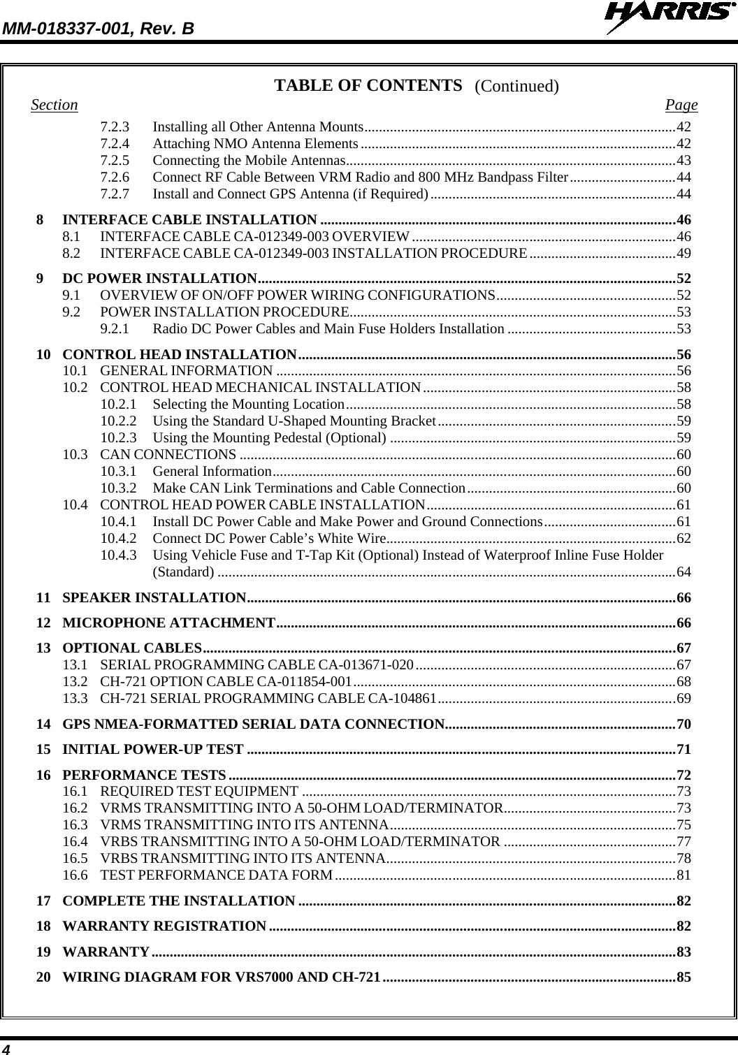
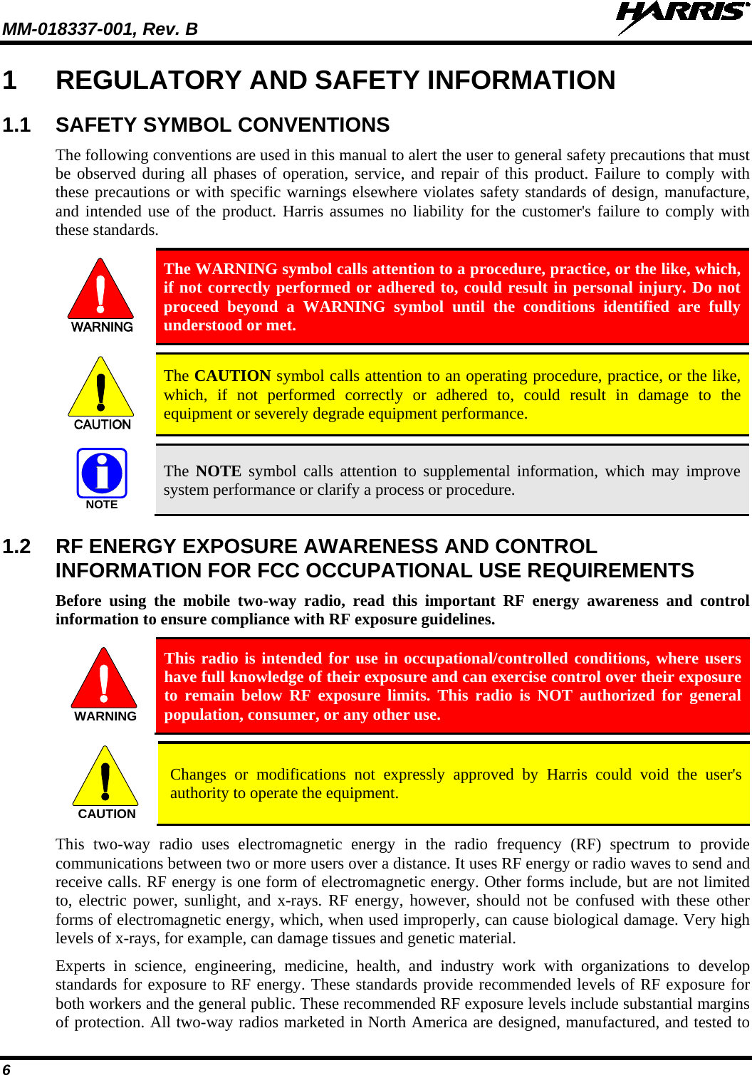
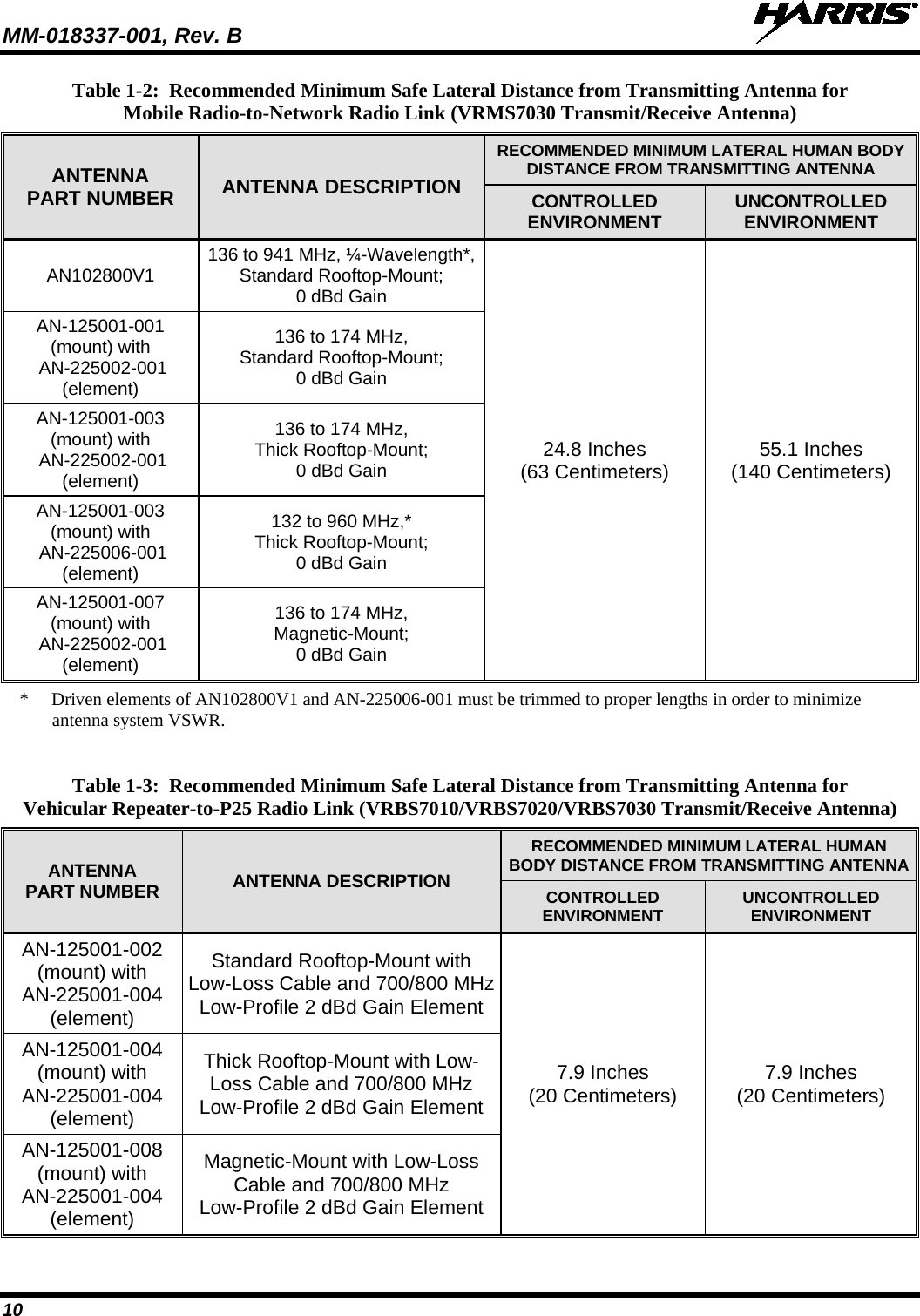
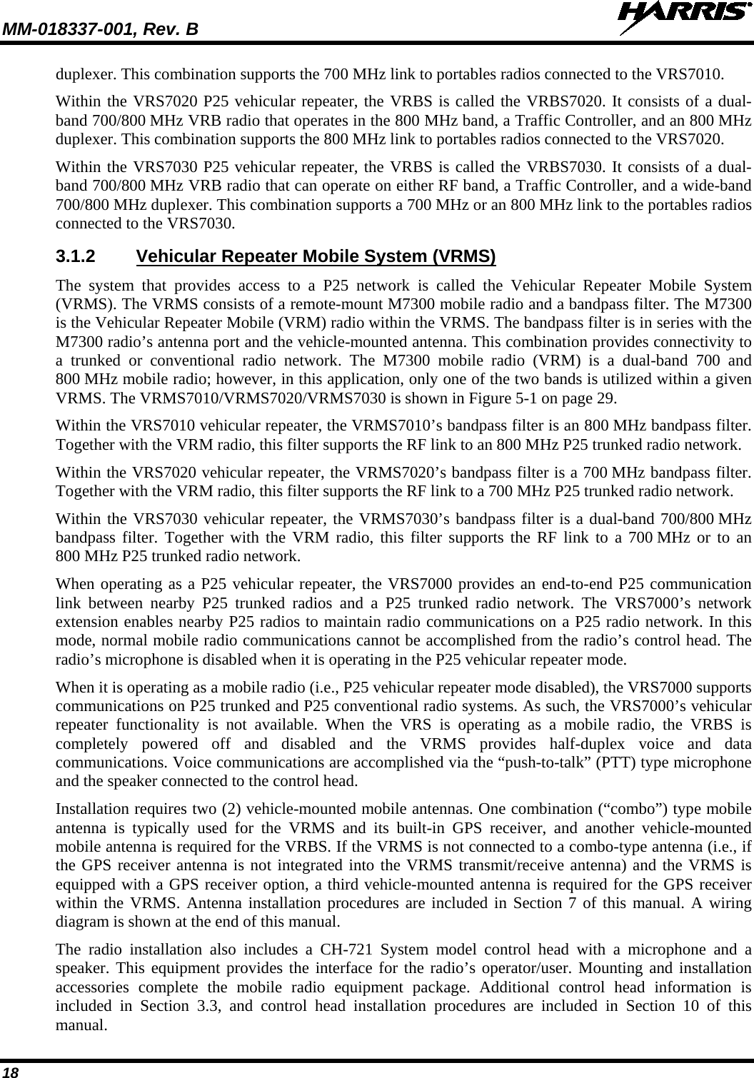
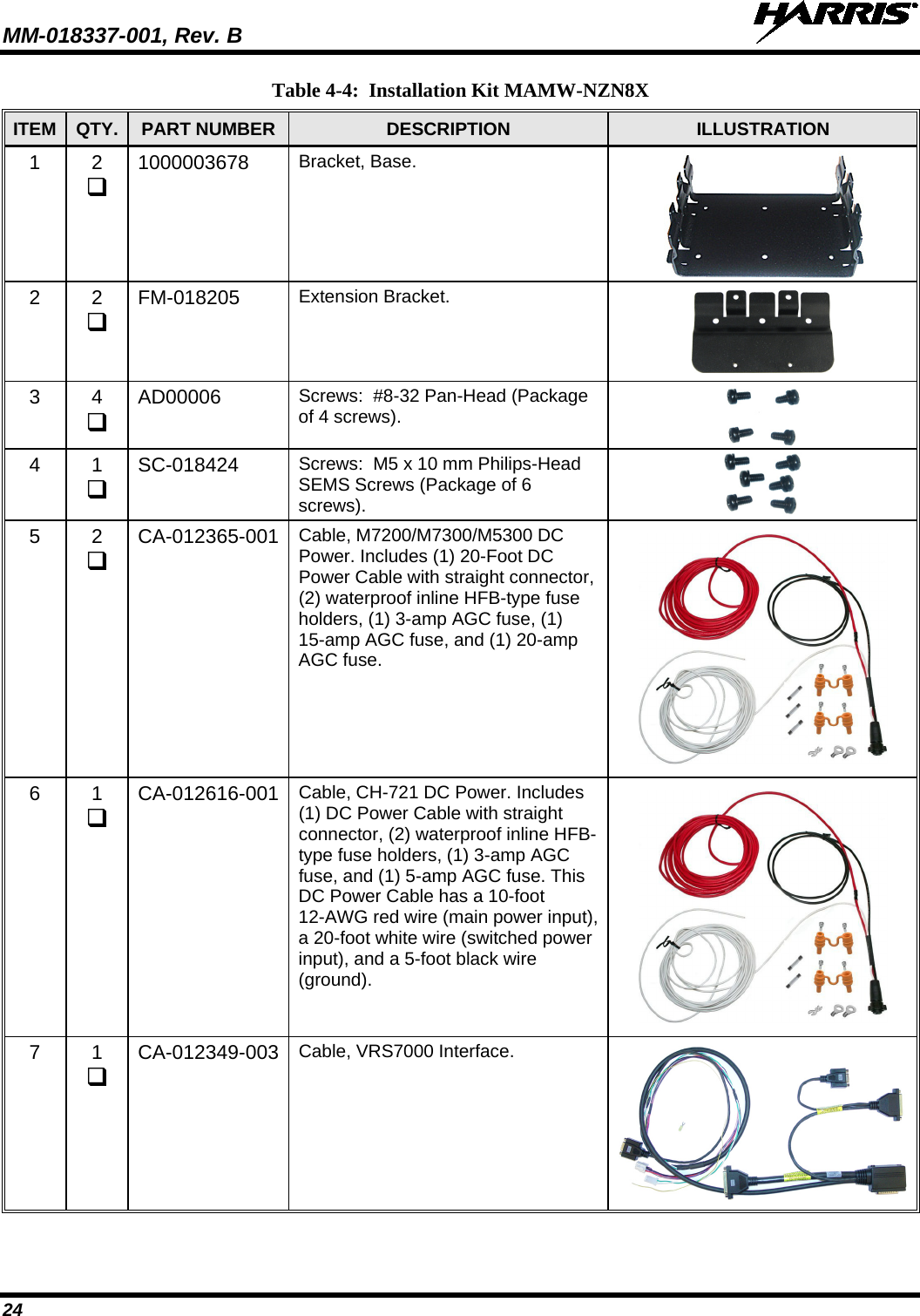
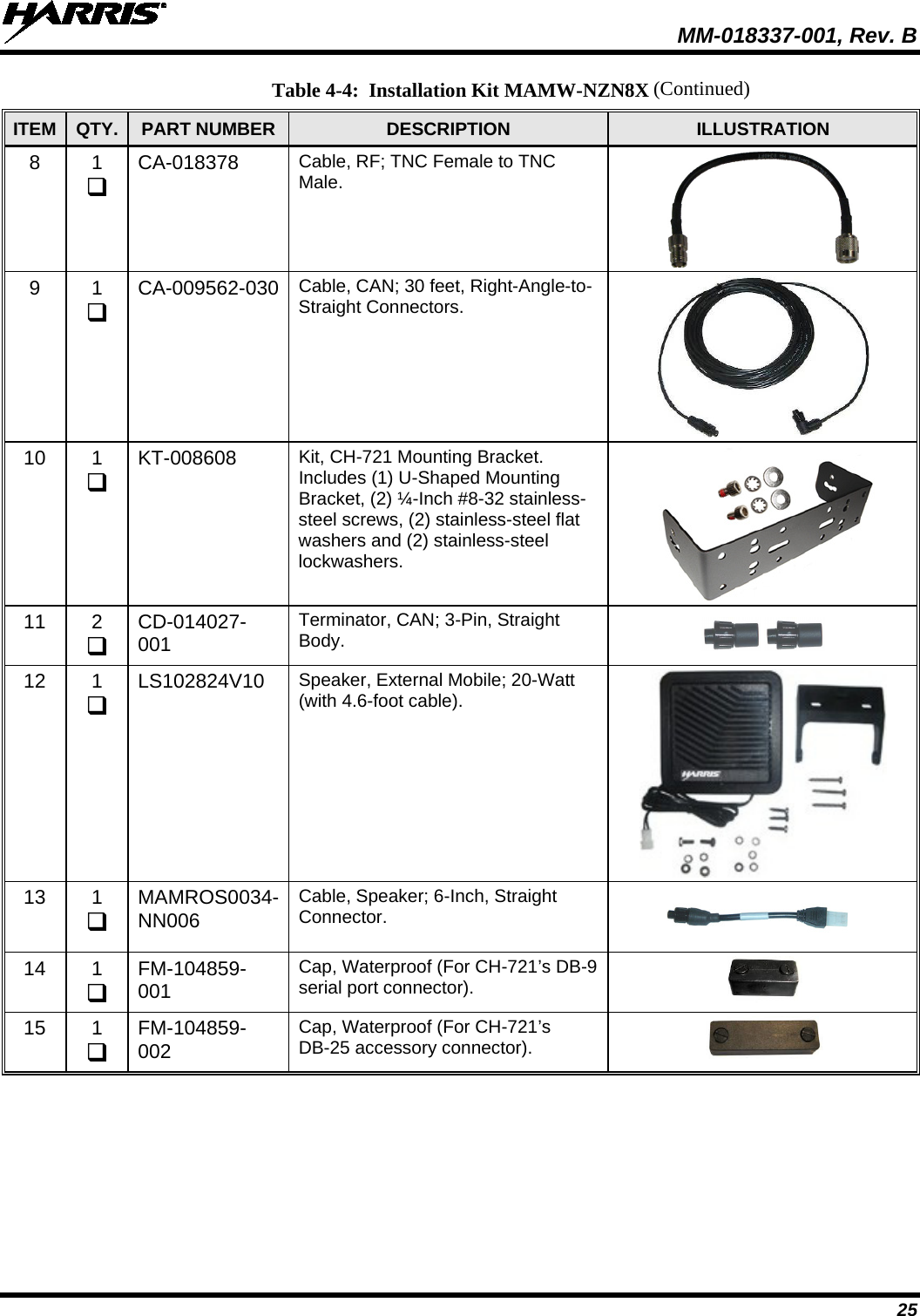
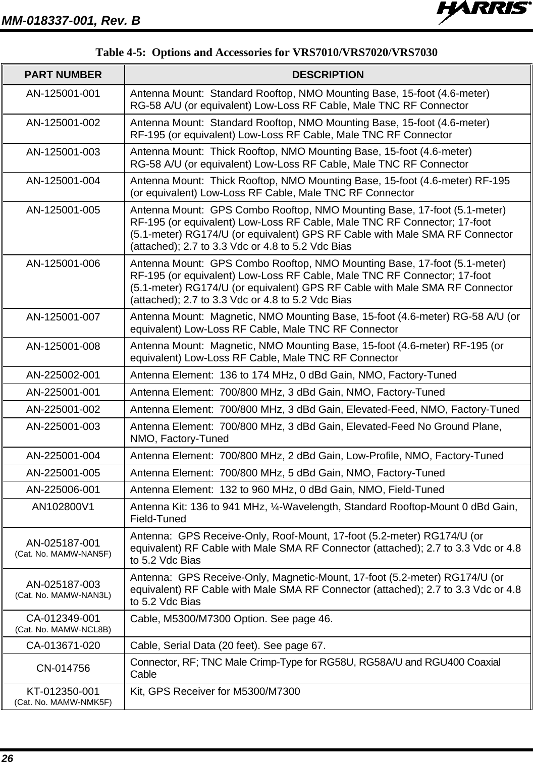
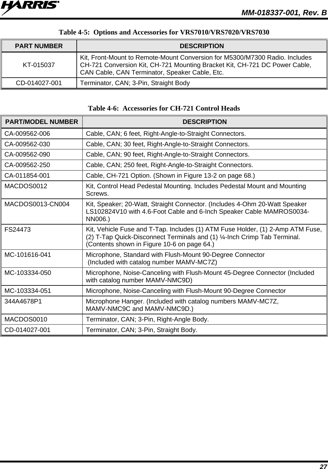
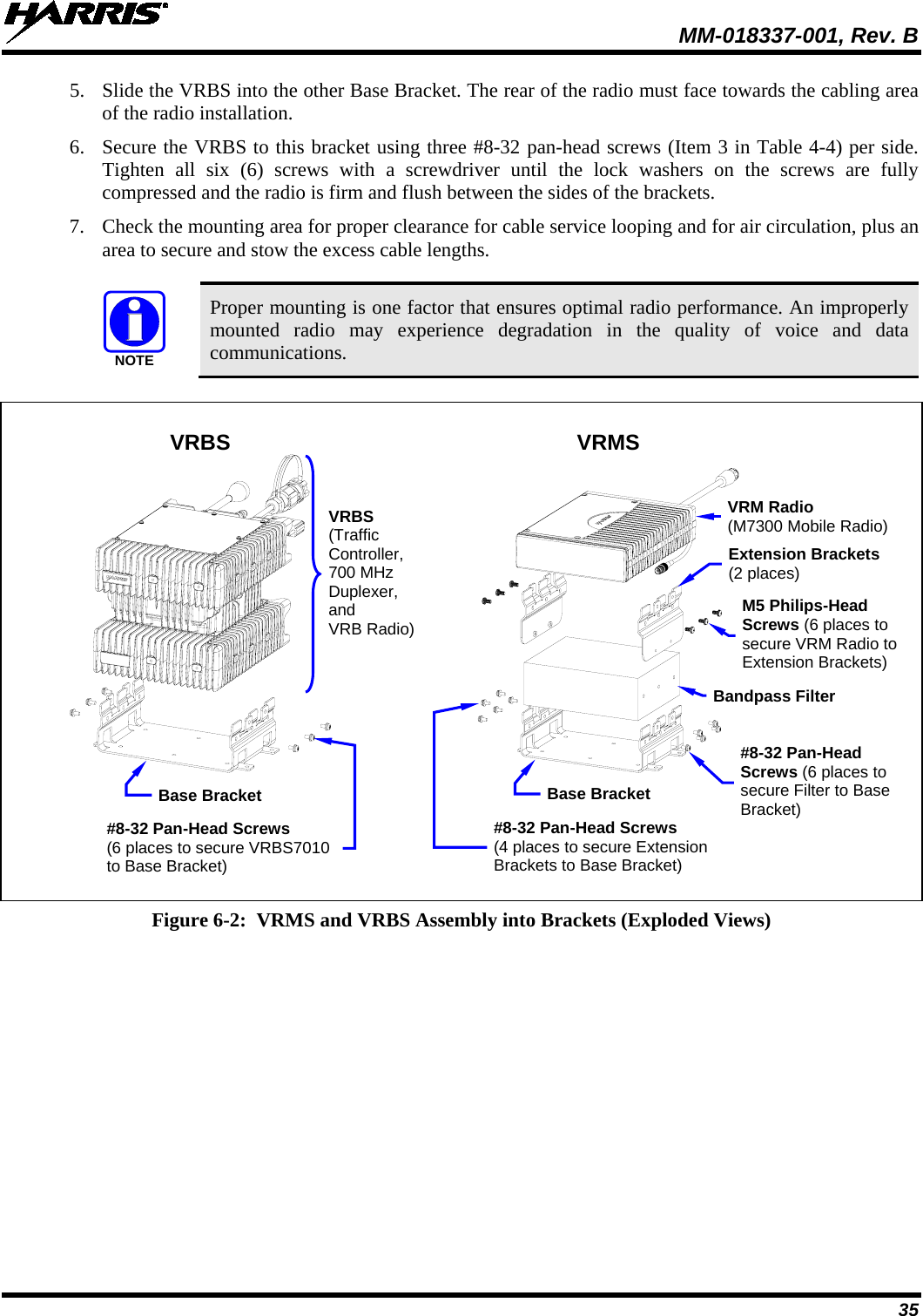
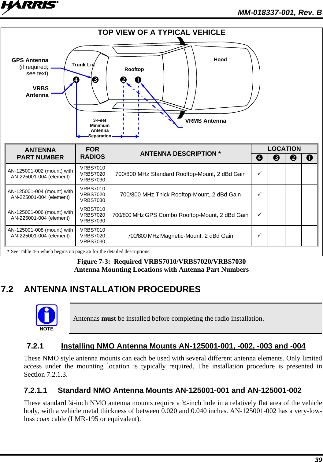
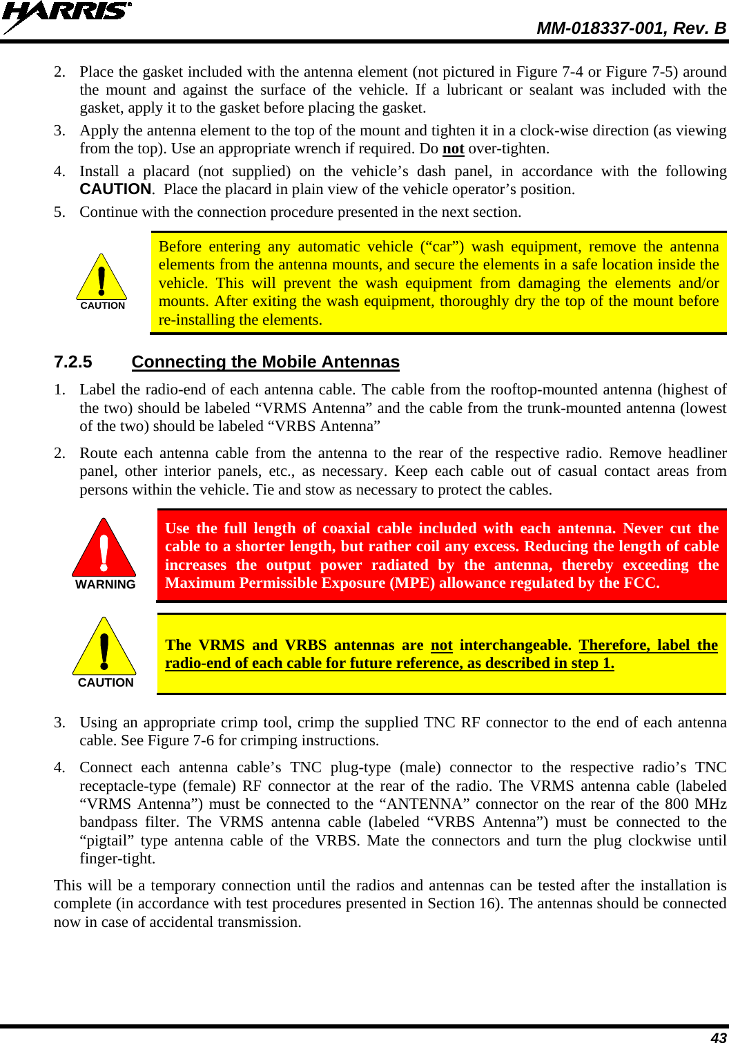
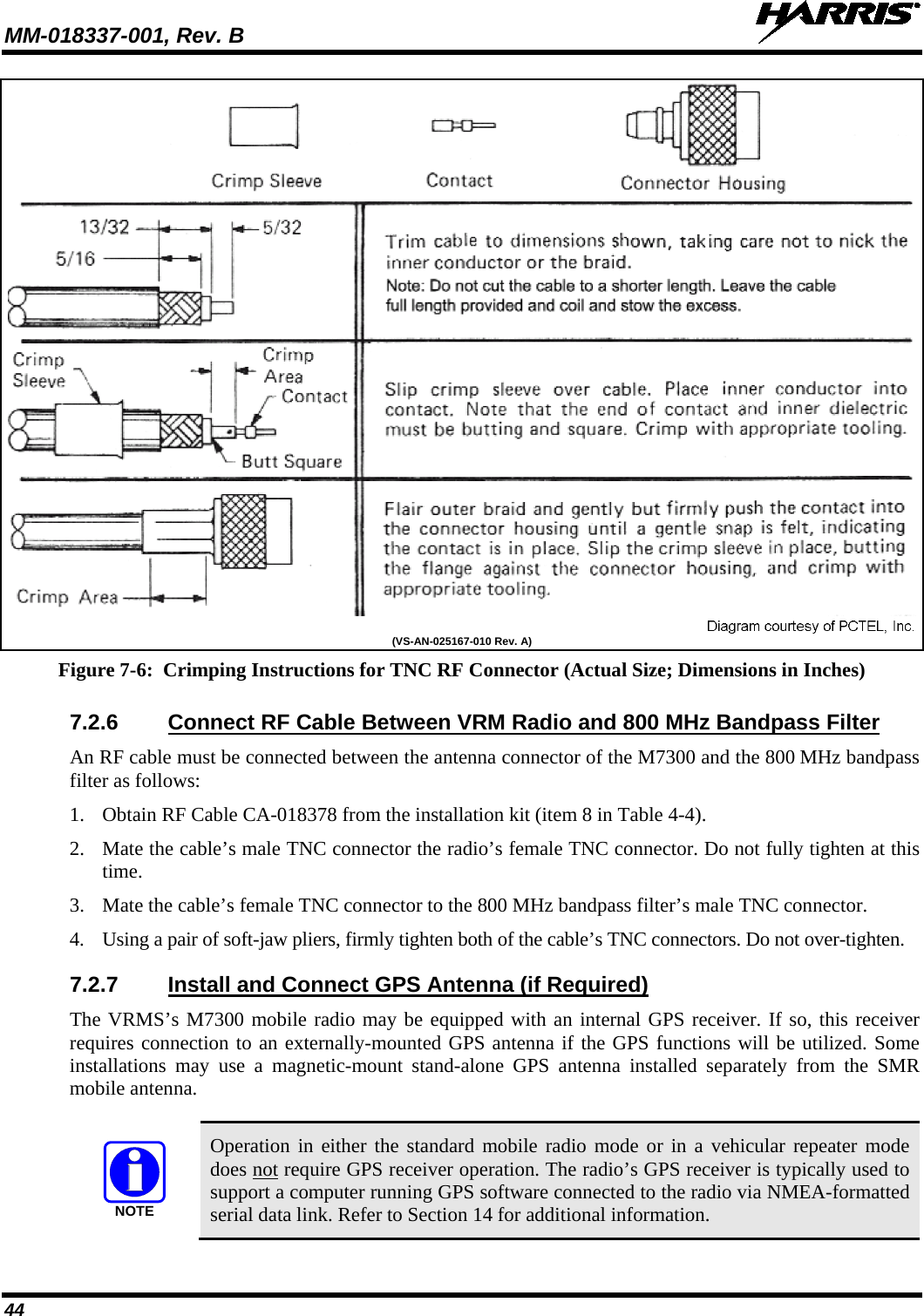
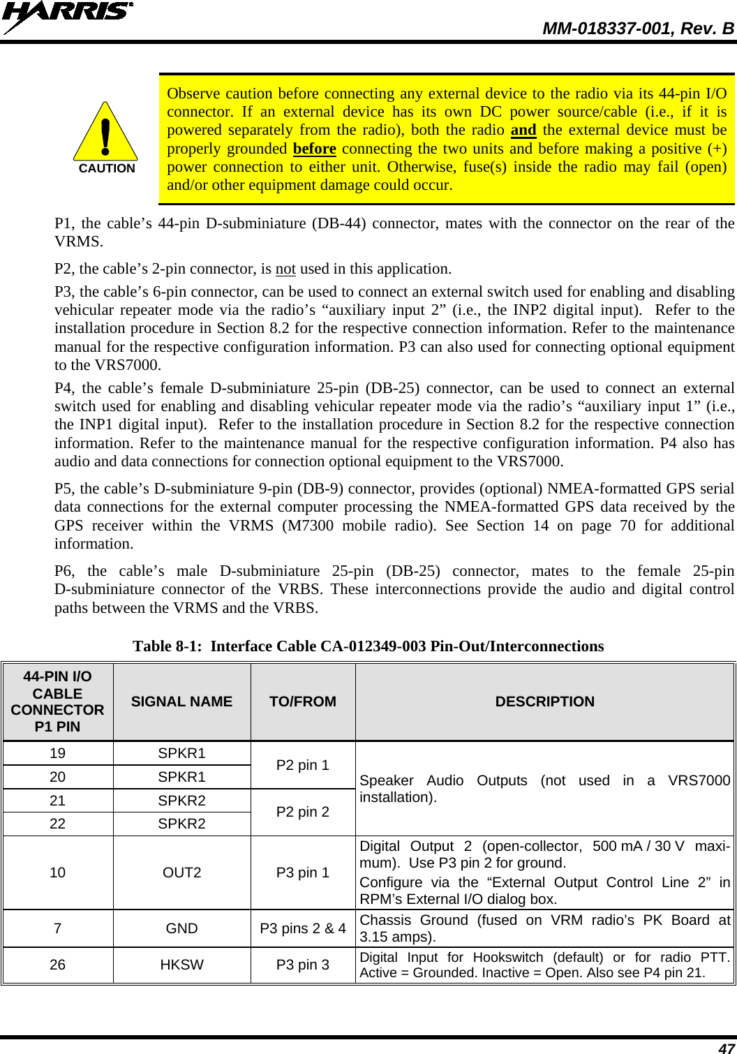
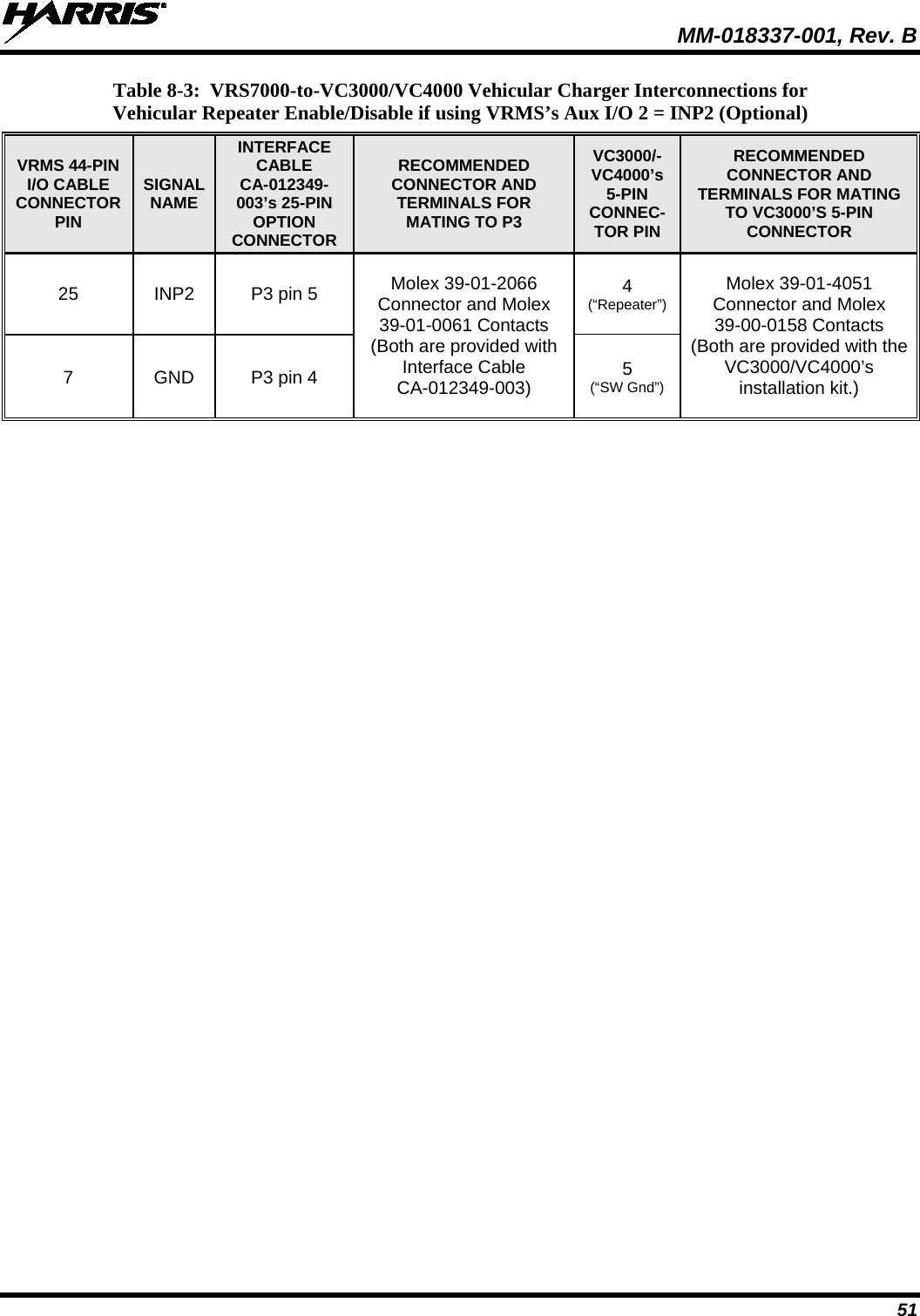
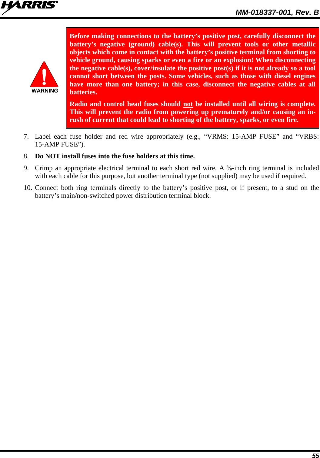
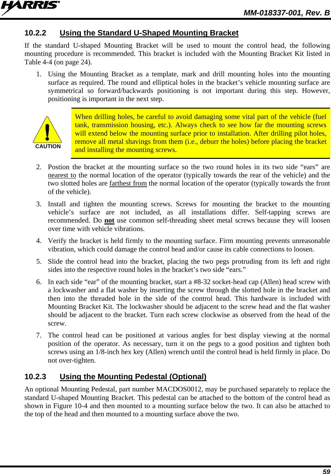
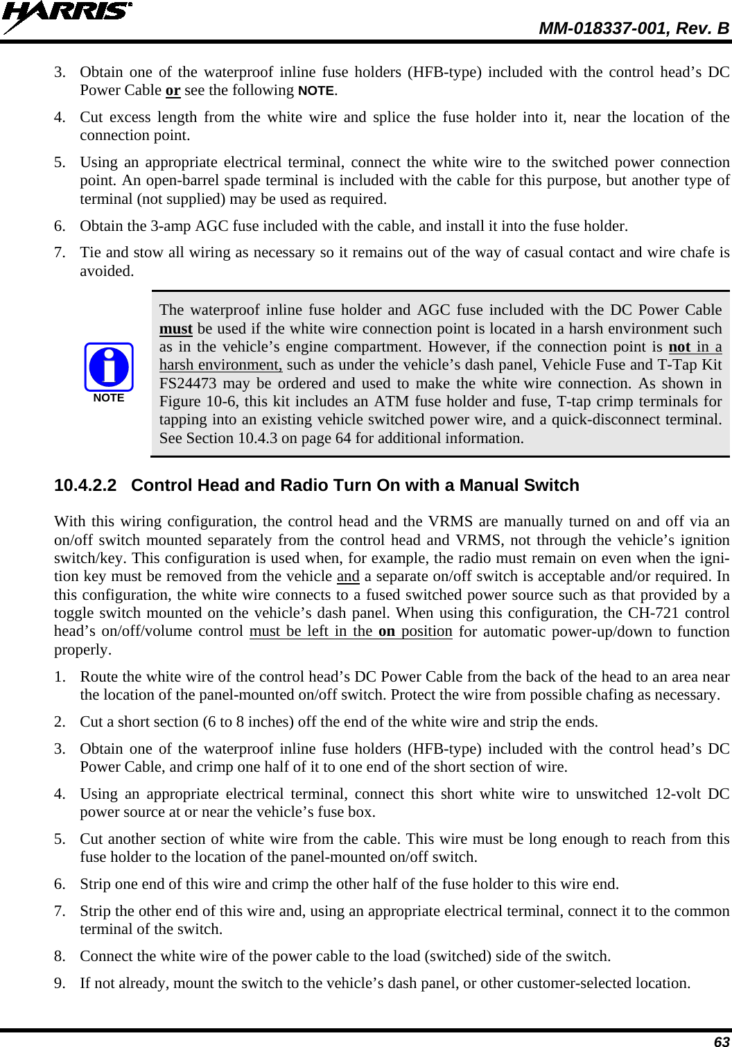
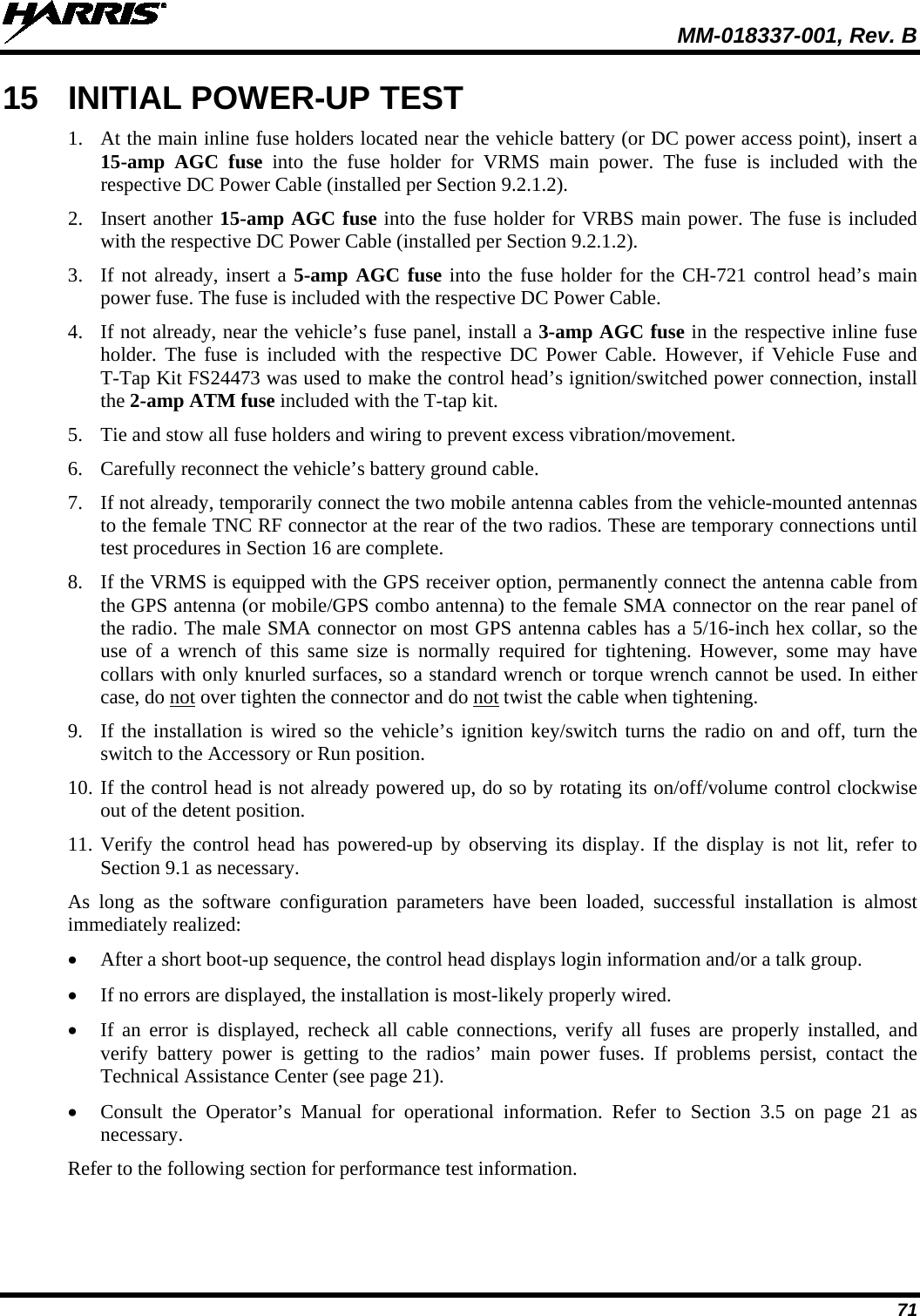
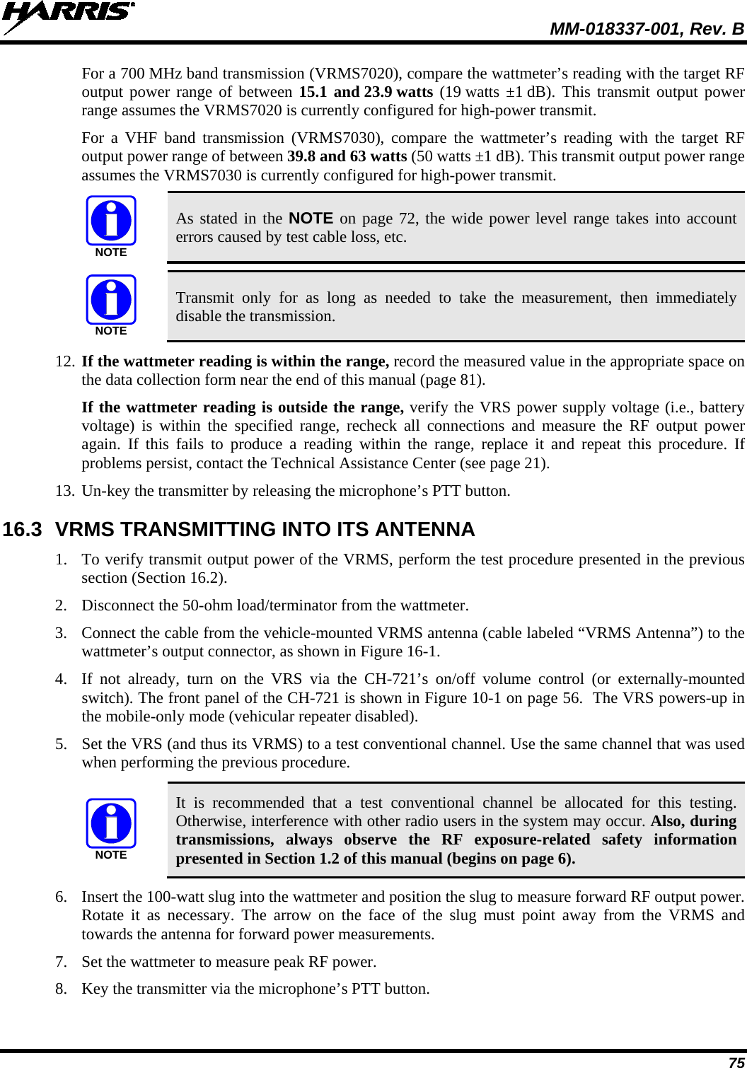
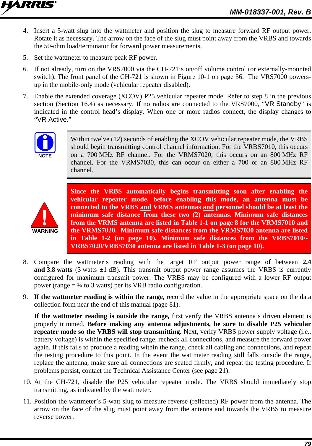
![MM-018337-001, Rev. B 22 4 UNPACKING AND CHECKING THE EQUIPMENT 4.1 MATERIALS A typical set of VRS7010/VRS7020/VRS7030 installation materials includes: • Vehicular Repeater Mobile System (VRMS7010/VRMS7020/VRMS7030), consists of: • M7300 Remote-Mount Mobile Radio • VRM Bandpass Filter (VRMS7010 and VRMS7020 only) • Vehicular Repeater Base System (VRBS7010/VRBS7020/VRBS7030) NOTE For catalog and part numbers, refer to the respective table that follows. • CH-721 System Control Head [part number CU23218-0004; catalog number MAMW-CP9F] • Standard Microphone [part number MC-101616-041; part of catalog number MAMW-MC7Z] • Installation Kit MAMW-NZN8X for VRS7010/VRS7020/VRS7030 and CH-721 as listed in Table 4-4 • Two (2) or Three (3) Antennas as listed in Table 4-5 The Installation Kit can be used to install the VRS7000, or individual components may be purchased separately as needed. Table 4-4 lists the parts included in the kit. Table 4-5 lists part numbers for radio options and accessories. Table 4-6 includes optional parts available for the CH-721 control head. Table 4-1: VRS7010 Catalog and Part Numbers CATALOG NUMBER PART NUMBER DESCRIPTION MAMW-SDMXX RU-144750-061 Remote-Mount Dual-Band 700/800 MHz M7300 Mobile Radio (VRM Radio of VRMS7010) MAMW-NFL1A FL-017938-010 800 MHz Bandpass Filter (Bandpass Filter of VRMS7010) MAMW-VDLXX RU-017933-010 VRBS7010 Table 4-2: VRS7020 Catalog and Part Numbers CATALOG NUMBER PART NUMBER DESCRIPTION MAMW-SDMXX RU-144750-061 Remote-Mount Dual-Band 700/800 MHz M7300 Mobile Radio (VRM Radio of VRMS7020) (TBD) FL-017938-020 700 MHz Bandpass Filter (Bandpass Filter of VRMS7020) (TBD) RU-017933-020 VRBS7020](https://usermanual.wiki/HARRIS/TR-0058-E.User-Manual-2/User-Guide-1632445-Page-22.png)
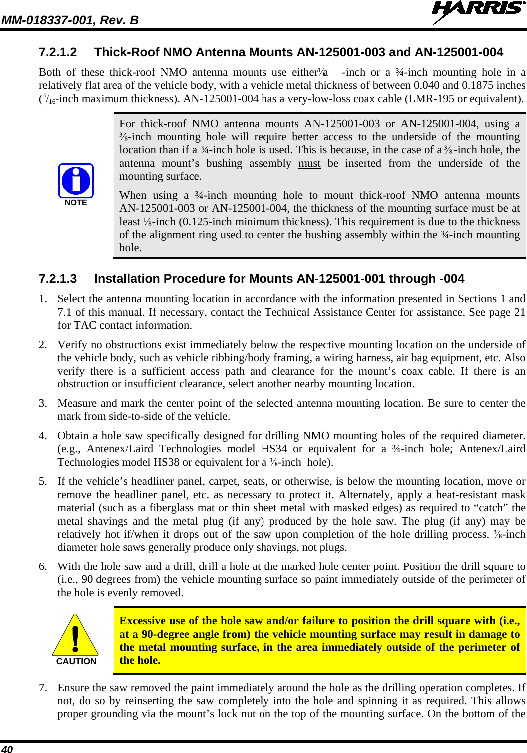
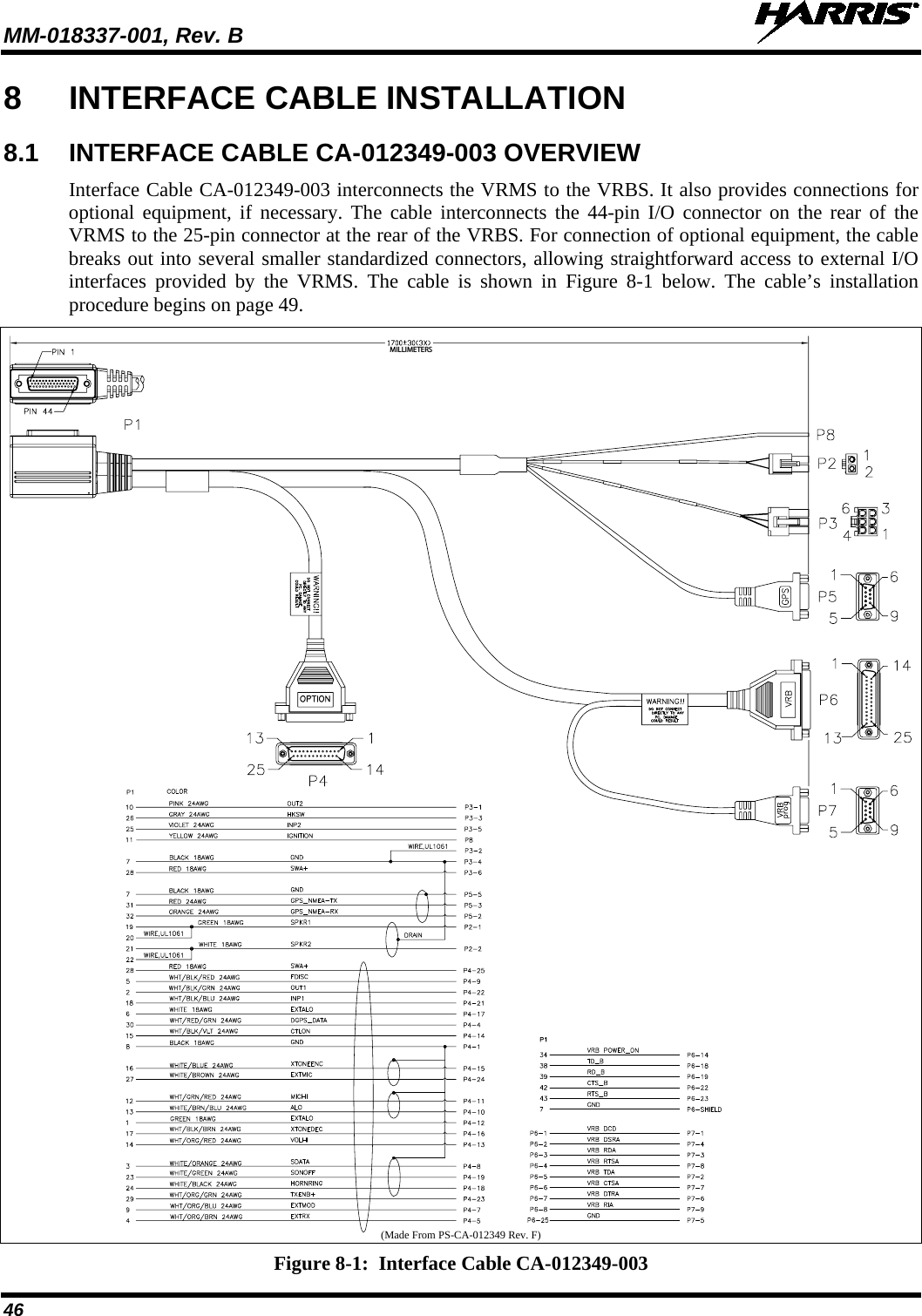
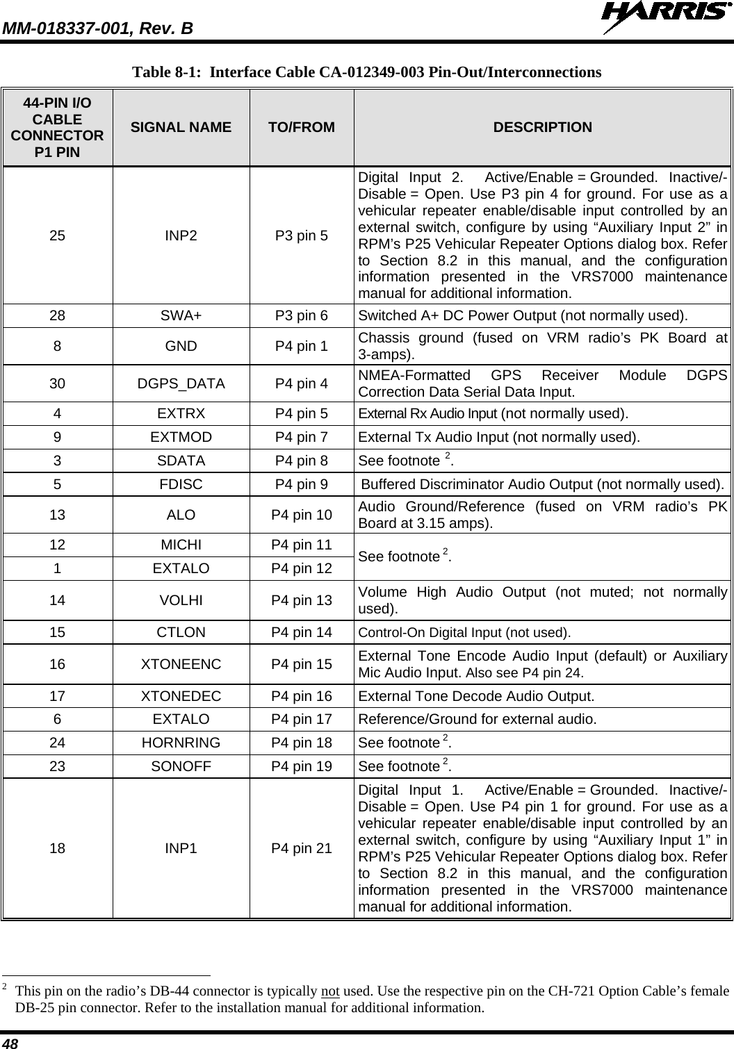
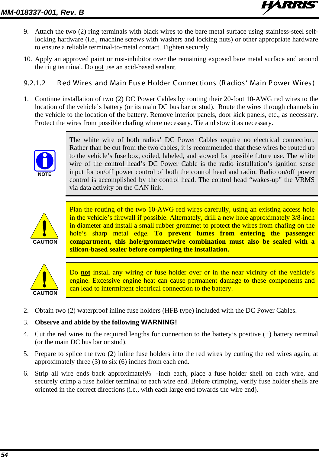
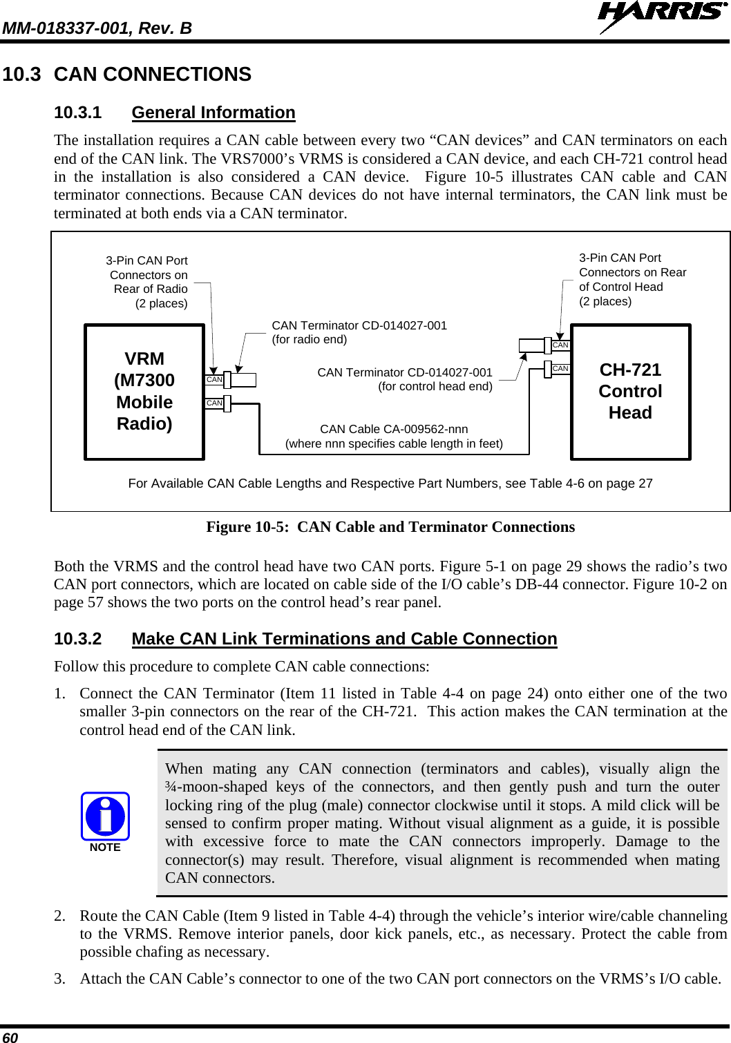
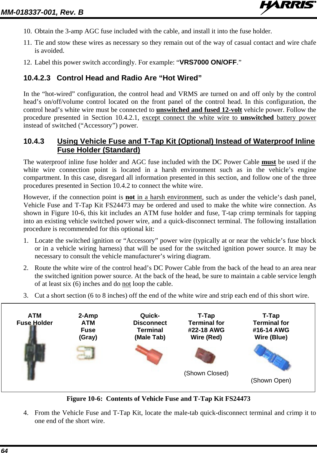
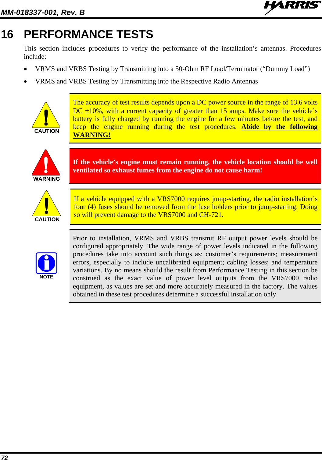
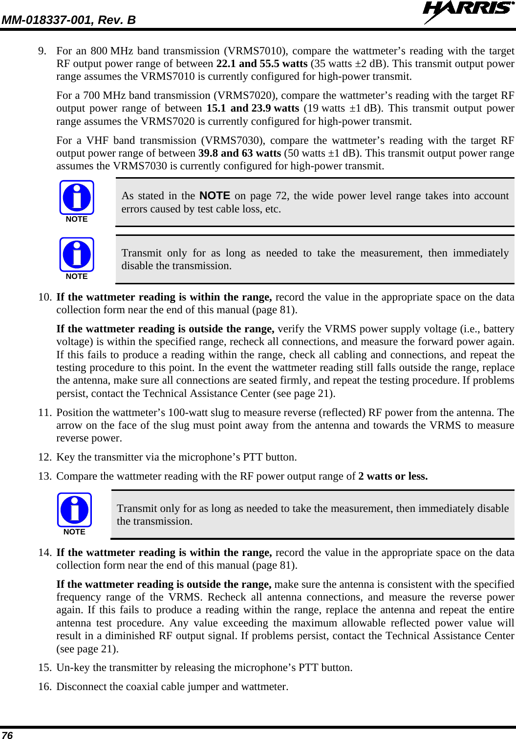
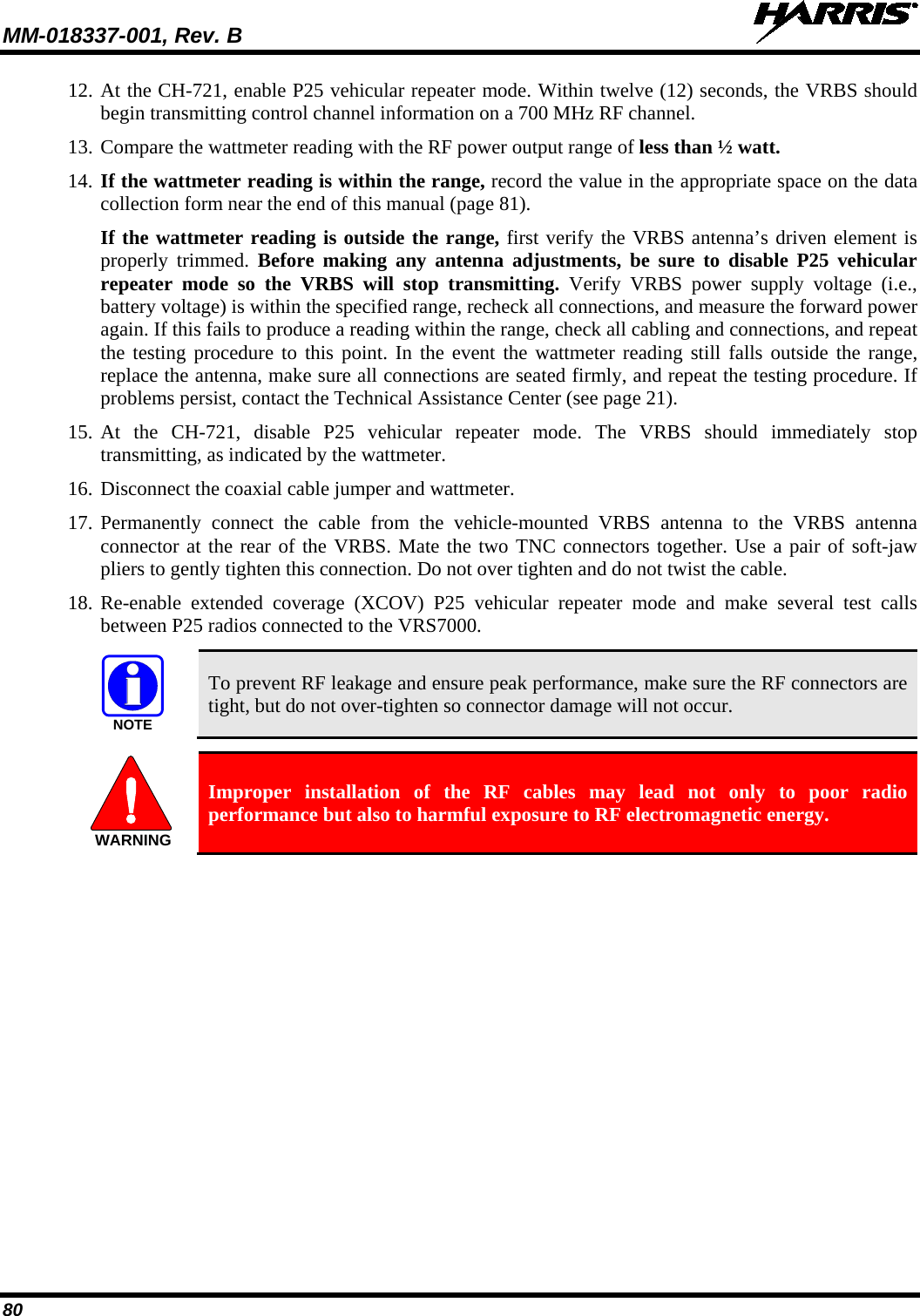

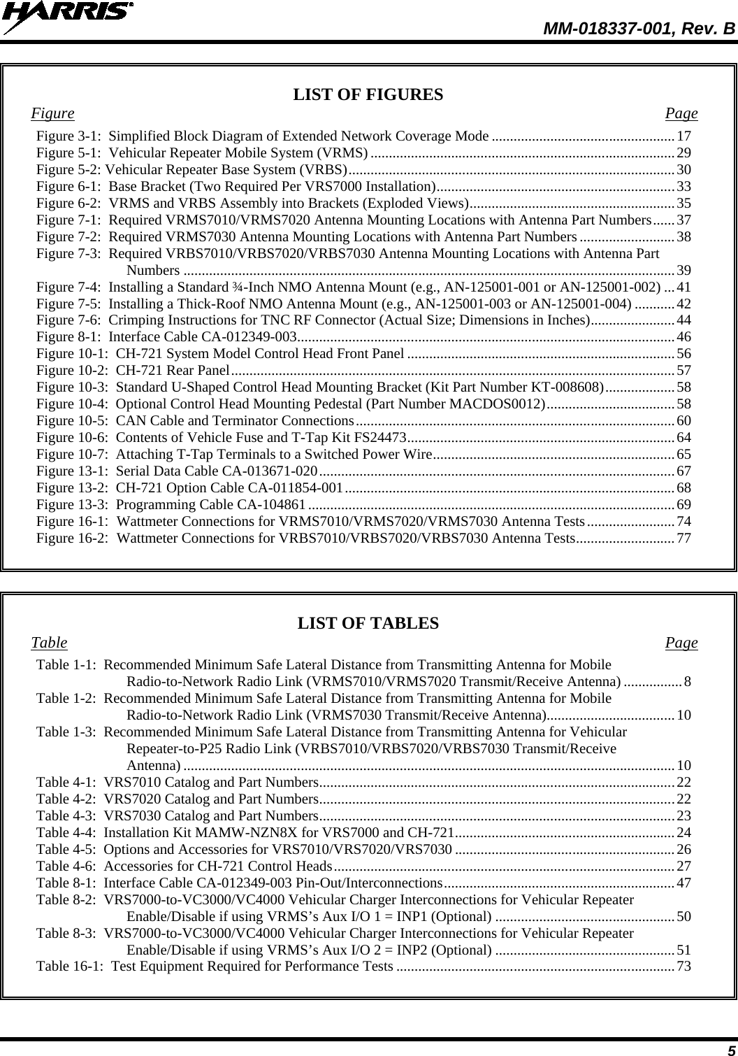
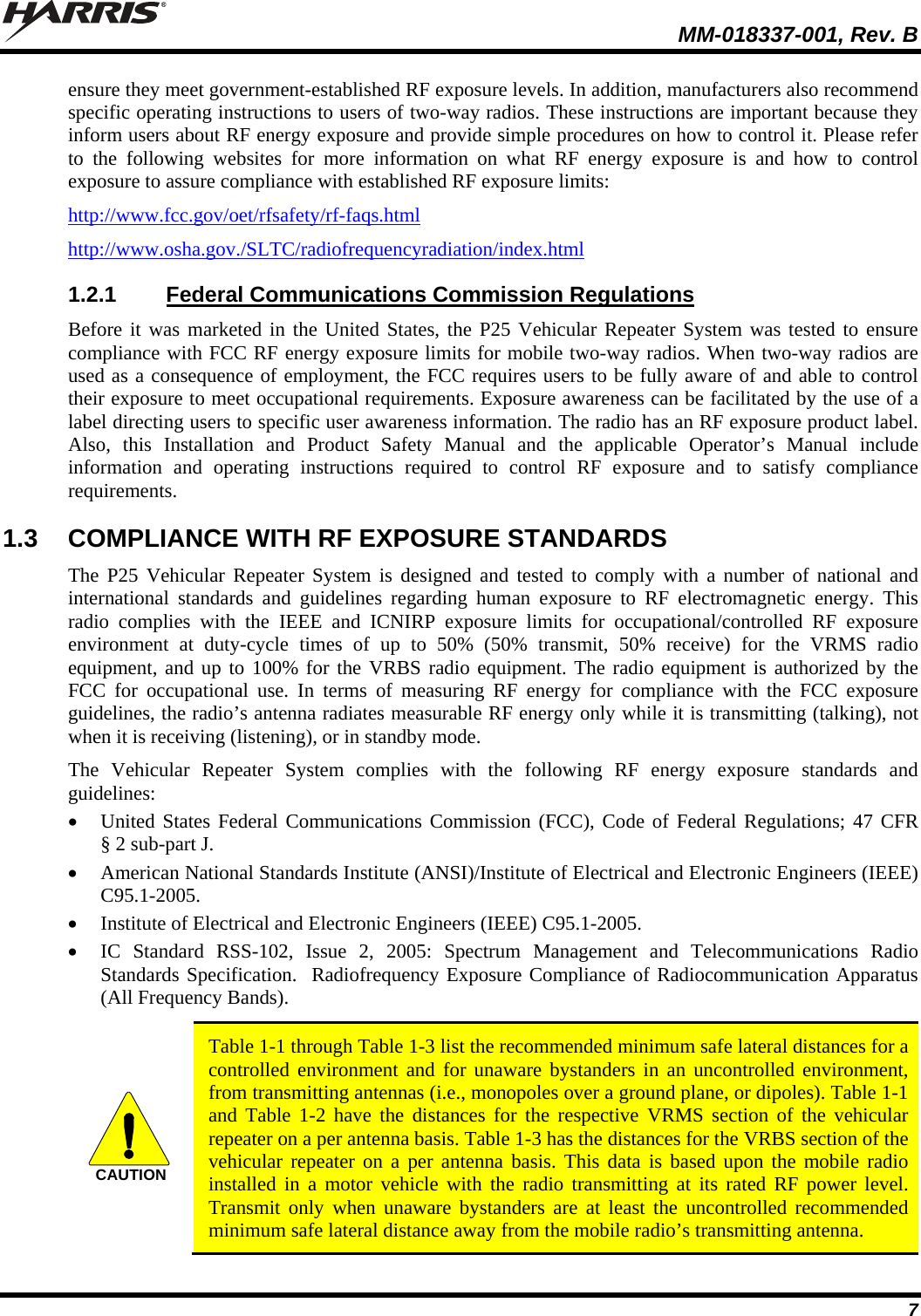
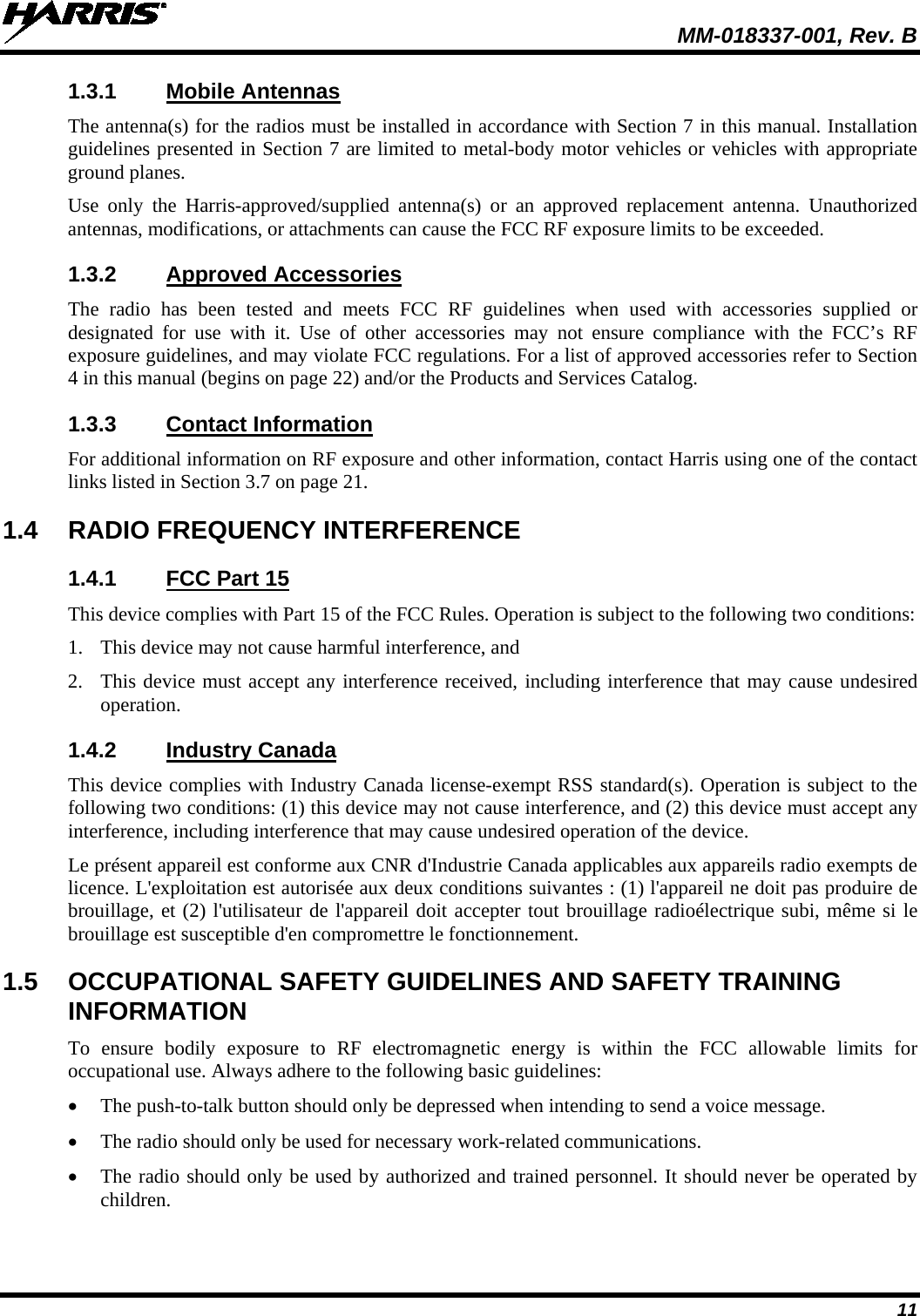
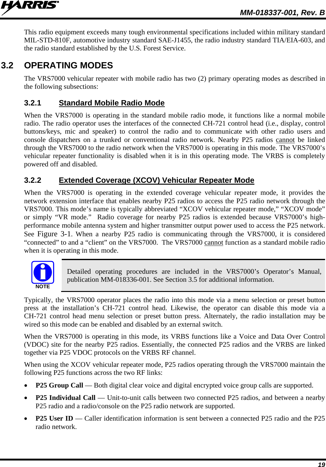
![MM-018337-001, Rev. B 85 CAN TERMINATORCD-014027-001[SUPPLIED WITH INSTALLAITON KIT]MALE TNC RF CONNECTOR(SUPPLIED WITH ANTENNA)VEHICLE-MOUNTEDGPS ANTENNA(OPTIONAL OR MAY BE INTEGRATED IN MOBILE ANTENNA)DC POWER CABLECA-012365-001(SUPPLIED WITH INSTALLATION KIT)CH-721 SYSTEM MODEL CONTROL HEADCU23218-0004(MAMW-CP9F)CH-721 MOUNTING BRACKET KITKT-008608[SUPPLIED WITH INSTALLATION KIT]• IF IGNITION SENSE ON/OFF FUNCTIONALITY IS REQUIRED, CONNECT WHITE WIRE OF CONTROL HEAD’S DC POWER CABLE TO A SWITCHED 13 VDC POWER SOURCE USING THE SUPPLIED FUSE AND FUSE HOLDER.• IF IGNITION SENSE ON/OFF FUNCTIONALITY IS NOT REQUIRED, CONNECT WHITE WIRE OF CONTROL HEAD’S DC POWER CABLE TO AN UNSWITCHED 13 VDC POWER SOURCE USING THE SUPPLIED FUSE AND FUSE HOLDER.WATERPROOF CAPFM-104859-001 (NOT SHOWN)FOR DB-9 SERIAL CONNECTOR[SUPPLIED WITH INSTALLATION KIT]WATERPROOF CAPFM-104859-002 (NOT SHOWN)FOR DB-25 ACCESSORY CONNECTOR[SUPPLIED WITH INSTALLATION KIT]REAR VIEW OF CONTROL HEADNEG POSBLACKREDWHITEREDVEHICLE-MOUNTEDVRBS ANTENNARED RED5-AMPFUSE& FUSE HOLDER (YELLOW)3-AMP FUSE & FUSE HOLDER (YELLOW)TWO15-AMPFUSES & FUSE HOLDERS(ORANGE)REDWHITEREDRINGTERMINALSVEHICLEDC POWER DISTRIBUTION BLOCK(E.G., “POWER ACCESS POINT”)VEHICLE BATTERY+-NOTE: BATTERY GROUND (-) CONNECTION NOT INDICATED.CAN TERMINATORCD-014027-001[SUPPLIED WITH INSTALLATION KIT]REDWHITEBLACK(SHORT AS POSSIBLE)RING TERMINAL (CONNECT TO VEHICLE CHASSIS GROUND)SPEAKER CABLEMAMROS0034-NN006[SUPPLIED WITHINSTALLATION KIT]EXTERNAL SPEAKERLS102824V10[SUPPLIED WITHINSTALLATION KIT] WHITE WIRES (2)OF DC POWER CABLES (LABELED AND COILED NEAR VEHICLE’S FUSE BOX)DC POWER CABLE CA-012616-001(SUPPLIED WITH INSTALLATION KIT)VEHICLE FUSE BOX, ETC.WHITE (2X)STANDARD MICROPHONEMC-101616-040 ORMC-101616-041(INCLUDED WITHMAMW-MC7Z)ORNOISE-CANCELINGMICROPHONEMC-103334-050 ORMC-103334-051(INCLUDED WITHMAMW-NMC9D)DC POWER CABLECA-012365-001(SUPPLIED WITH INSTALLATION KIT)RINGTERMINALS (CONNECT TO VEHICLECHASSIS GROUND)BLACKREDREDWHITEINTERFACE CABLECA-012349-003(SUPPLIED WITH INSTALLATION KIT)MALE TNC RF CONNECTOR(SUPPLIED WITH ANTENNA)VEHICLE-MOUNTEDVRMS ANTENNAREDVRBS(REAR VIEW)VRBS7010 (700 MHz) = RU-017933-010VRBS7020 (800 MHz) = RU-017933-020VRBS7030 (700/800 MHz) = RU-017933-030CAN CABLE CA-009562-030 (30 FEET LONG)[SUPPLIED WITH INSTALLATION KIT]MALE SMA RF CONNECTOR(SUPPLIED WITH ANTENNA)VRMS(REAR VIEW)EXTENSION BRACKETFM-018205(QTY. = 2) BASE BRACKET1000003678RF CABLECA-018378(SUPPLIED WITH INSTALLATION KIT; NOT USED WITH VRMS7030)(DB-9 CONNECTOR FOR VRB RADIO PROGRAMMING)(COMMON GROUND POINT FOR BOTH RADIOS)M7300 MOBILE RADIOVRMS7010 = RU-144750-061VRMS7020 = RU-144750-061VRMS7030 = RU-144750-041BANDPASS FILTERVRMS7010 = FL-017938-010VRMS7020 = FL-017938-020BASE BRACKET1000003678RADIO20 WIRING DIAGRAM FOR VRS7000 AND CH-721 VRS7000 AND CH-721 WIRING DIAGRAM](https://usermanual.wiki/HARRIS/TR-0058-E.User-Manual-2/User-Guide-1632445-Page-85.png)