HID Global 4045 4045C Entry Prox User Manual 555249
HID Global Corporation 4045C Entry Prox 555249
UserManual.wiki
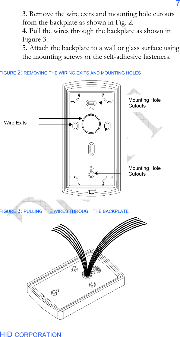
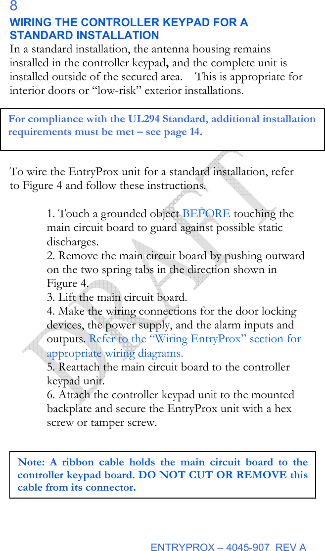
>
HID Global
>
4045 User Manual
>
Users Manual
Contents
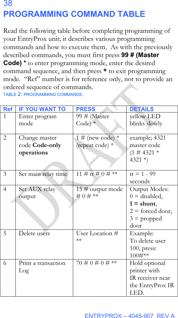
1.
manual
2.
Users Manual
Users Manual
Navigation menu
Upload a User Manual
Namespaces
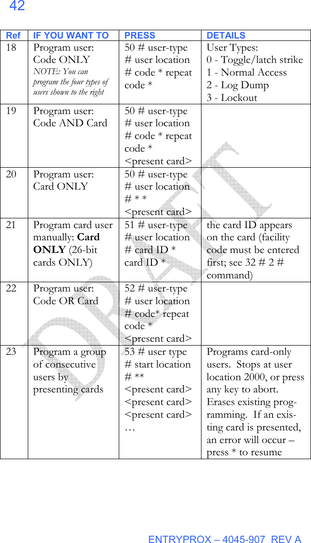
Wiki Guide
HTML
PDF
Info
Views
User Manual
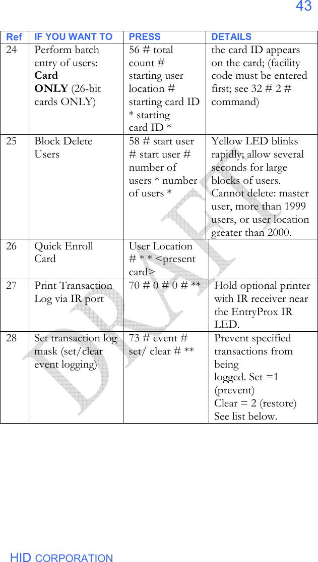
Discussion / Help
Navigation


![ENTRYPROX – 4045-907 REV A 34 CHANGING OPERATING PARAMETERS Many users will use the EntryProx with the factory default operating parameters. The following commands include some of the most commonly customized parameters. For further refinements on EntryProx operation, review the options shown in Table 2. CHANGING THE MAIN RELAY TIME The main relay time applies to all users 1-2000. The factory default main relay time is five (5) seconds. Main relay time can be set from one to ninety-nine seconds in one-second increments using Command 11. 1. Place the EntryProx unit in program mode. Press: 99 # Master Code * (default is 1234) 2. Enter the new main relay time, in seconds (from 1 to 99). For example, to enter 10 seconds, press: 11 # 10 # 0 # ** 3. Press * to exit program mode. INVALID PIN LOCKOUT Command 30, Option 18 allows you to enable or disable the Invalid PIN Lockout (IPL) feature. This feature prevents unauthorized persons from gaining entry by guessing PIN codes or Master Codes. When a preset number of invalid entries is exceeded (set by using Command 32 – option 4, default is 5) the EntryProx will either trigger the Forced Door output, or the keypad will be disabled for a user-configurable time period (select the action, using Command 30, option 19, and then set lockout time by using Command 32 – 5). The invalid PIN code count is reset to zero by any of the following: entering a valid keypad PIN presenting a programmed Prox card entering a valid [ 99 # Master code* ] sequence the expiration of the keypad timer](https://usermanual.wiki/HID-Global/4045.Users-Manual/User-Guide-555249-Page-38.png)
![HID CORPORATION 35 The Invalid PIN Lockout function disables all keypad PIN entries with the exception of the [ 99 # Master Code* ] sequence for the duration of the lockout. To clear an active timed Invalid PIN Lockout: • disconnect power to the system • present a valid prox card programmed as “Card Only” or “Card OR Code” • Enter the [ 99 # Master Code * ] sequence Note that if an invalid [ 99# Master Code* ] is entered as part of the sequence to clear the IPL, a good [99# Master Code* ] sequence will not cancel the current lockout. RESETTING THE MASTER CODE AND SYSTEM DEFAULTS ONLY Command 40 erases everything from the EntryProx memory except the user list and transaction log and restores the default settings. This is useful if the EntryProx unit has experienced programming problems, or if you wish to delete earlier programming. 1. Place the EntryProx unit in program mode. Press: 99 # Master Code * (default is 1234) 2. Press: 40 # 00000 # 00000 # ** 3. Press * to exit program mode. ERASING ENTIRE MEMORY / RESETTING SYSTEM DEFAULTS Command 46 deletes everything from the EntryProx memory including the user list but not the transaction log and restores the default settings. This is used as a last resort if you need to erase a specific user and could not retrieve the Programmed User List.](https://usermanual.wiki/HID-Global/4045.Users-Manual/User-Guide-555249-Page-39.png)
![HID CORPORATION 37 WIEGAND MODE If you program the EntryProx unit to operate in Wiegand mode with a separate access control panel, the following features are not accessible: • The EntryProx unit does not control door lock or unlocking operations. • The EntryProx unit is not able to store codes in memory. • The main and auxiliary relay functions are turned off. • The door monitor and Request to Exit inputs are disabled. For more information on programming the EntryProx unit for Wiegand operation, please contact your local distributor. PIN CODE OUTPUT IN WIEGAND MODE The system transmits keypad PINs while operating in Wiegand mode by processing any digit sequence terminated with the [*] key as 26-bit Wiegand data. The current facility code (set using Code 32 - 2) will be used. Entering any PIN over 65535 will cause an error condition and no data will be sent. Because keypad data is sent in a card data format, it may not be possible for some panels to perform CARD AND CODE operation (requiring both) to gain access. If your panel cannot accept and interpret 26-bit format as PIN data, be sure to configure the user at the PC host software by entering the code into the CARD data field for that user, not the keypad PIN number field.](https://usermanual.wiki/HID-Global/4045.Users-Manual/User-Guide-555249-Page-41.png)
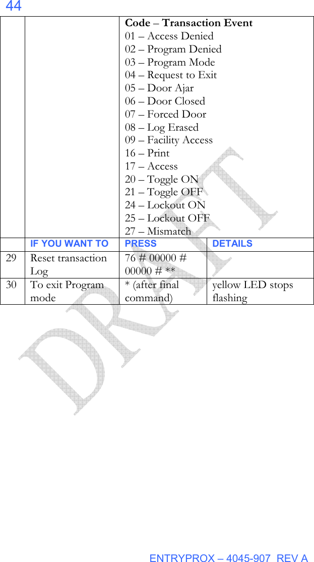
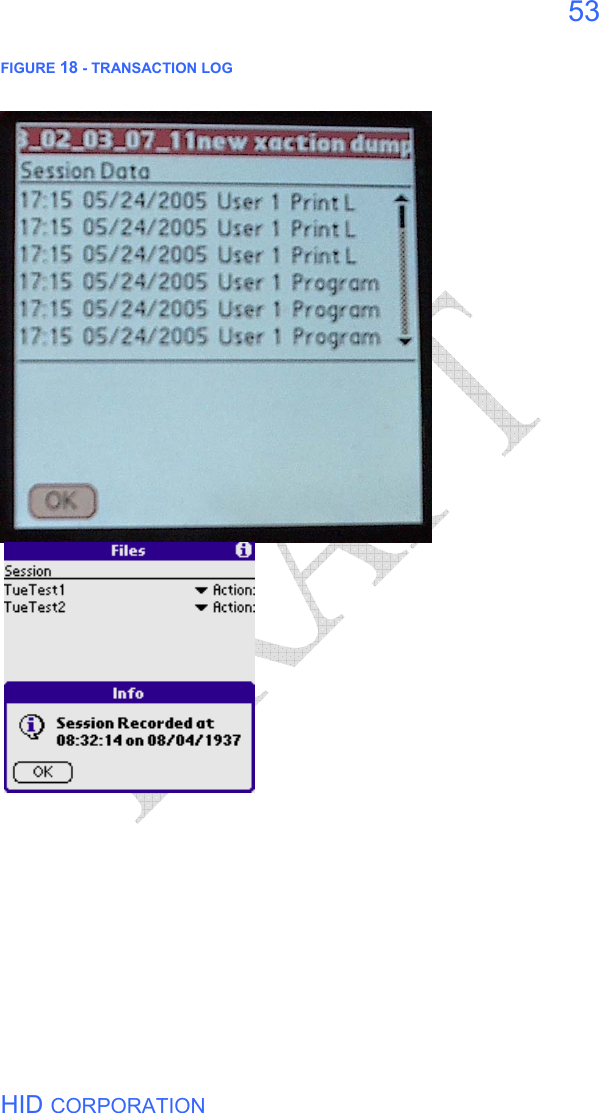
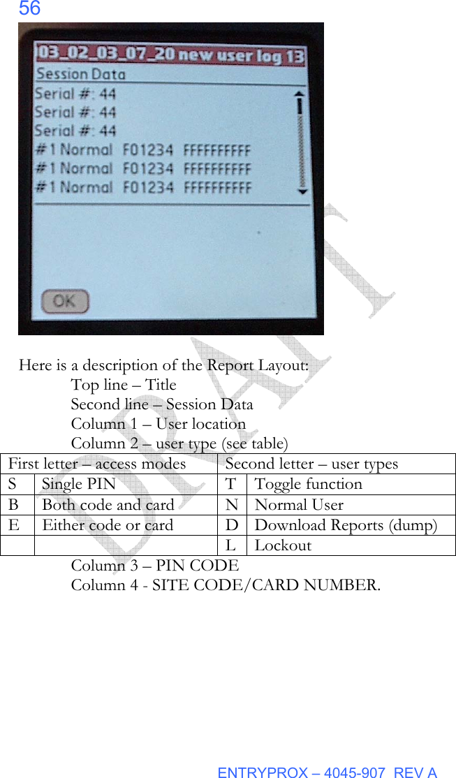
![ENTRYPROX – 4045-907 REV A 54 The Palm PDA will store reports after they are downloaded. To view a stored report, touch Files, select a report from the list and click on Action. The drop-down menu selections are Info, View and Remove. Info gives the time and date the report was recorded. Remove allows you to delete the report. View displays the report. The top line of the screen shows the current line and total number of lines as you scroll or page up and down through the report. Here is a description of the report layout: Top line – Current Line/Total Lines Second line – Session Data Transaction lines: Time, Date, User Location, Action TIME - 24-hour format. Date: mm/dd/yyyy User Location (1-2000) ACTION describes each event ERASING A TRANSACTION LOG The Transaction Log should be erased from memory in the EntryProx after being downloaded to prevent conflicting logs. To erase the log, enter the following sequence: 1. Place the EntryProx unit in program mode. Press: 99 # Master Code * (default is 1234)] 2. To erase the transaction log press: 76 # 00000 # 00000 # ** 3. Press * to exit program mode. DOWNLOADING A PROGRAMMED USERS LIST The Programmed Users List can be downloaded to the optional Palm PDA via the unit’s IR port. The list identifies the user location for each user’s data.. It also displays user locations that are not programmed, so to avoid an unnecessarily long file, the download can be stopped when a](https://usermanual.wiki/HID-Global/4045.Users-Manual/User-Guide-555249-Page-58.png)
![HID CORPORATION 55 sufficient percentage of records have been processed. The percentage of records downloaded is continually updated during the download process. 1. Place the EntryProx unit in program mode. Press: 99 # Master Code * (default is 1234)] 2. Hold the optional PDA up to the EntryProx IR port steadily (about ½ inch away; the IR port is located to the right of the yellow LED) 3. Start the DCD program on the Palm PDA, then touch Retrieve on the PDA 4. Then, on the EntryProx, press 25 # 0 # 0 # ** The PDA will display a progress bar while collecting the data (Retrieving users %) and when done will display End of Dump. You can touch Close/Stop on the PDA or wait for the unit to time out. When prompted for a Session Name, you can place your stylus on the line containing the date information and add to it or replace it with descriptive text. 3. When the list is complete, press * to exit program mode. FIGURE 19 - PROGRAMMED USER LIST](https://usermanual.wiki/HID-Global/4045.Users-Manual/User-Guide-555249-Page-59.png)