HID Global 5553 HID5553—Multi-ISO RFID Reader User Manual HID Install Guide
HID Global Corporation HID5553—Multi-ISO RFID Reader HID Install Guide
UserManual.wiki
>
HID Global
>
5553 User Manual
User Manual
Navigation menu
Upload a User Manual
Namespaces
Wiki Guide
HTML
PDF
Info
Views
User Manual
Discussion / Help
Navigation
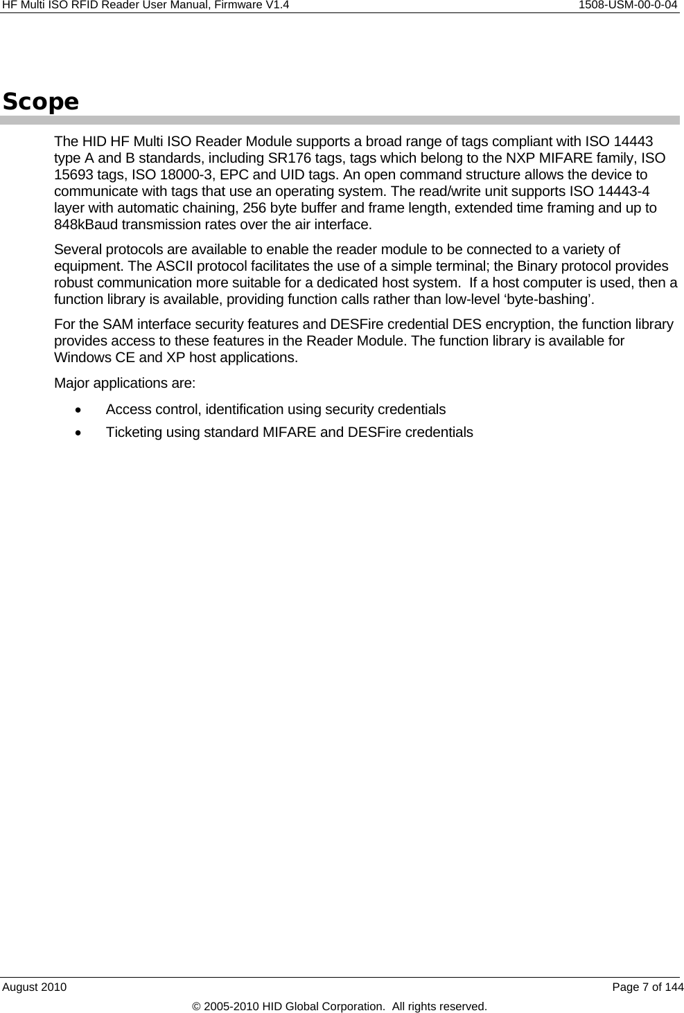
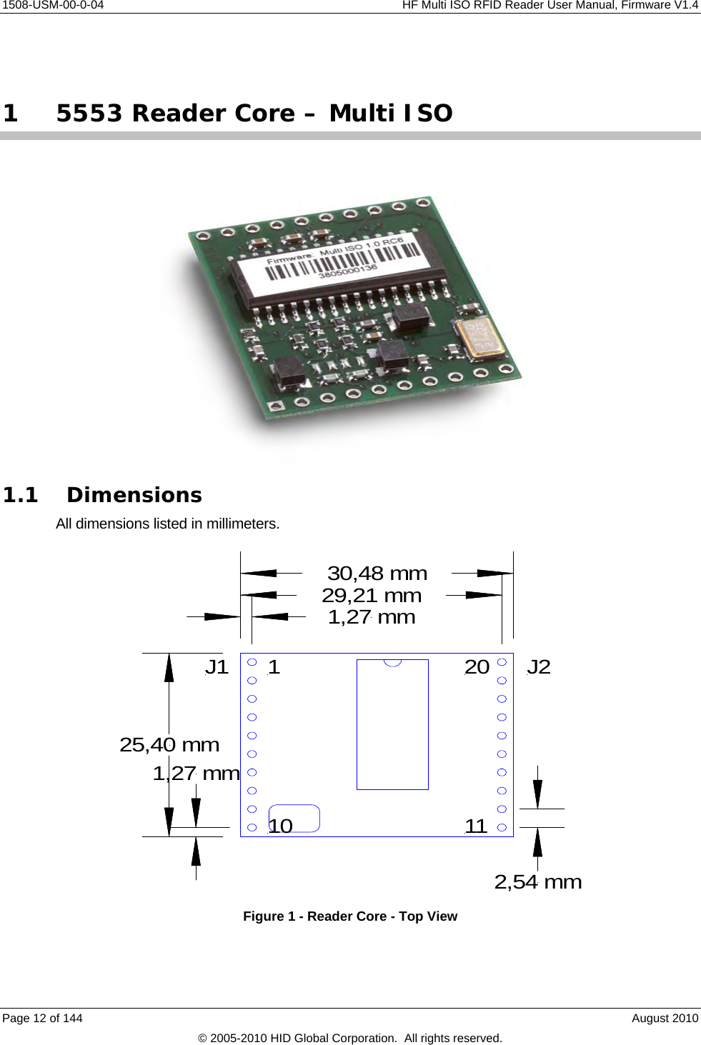
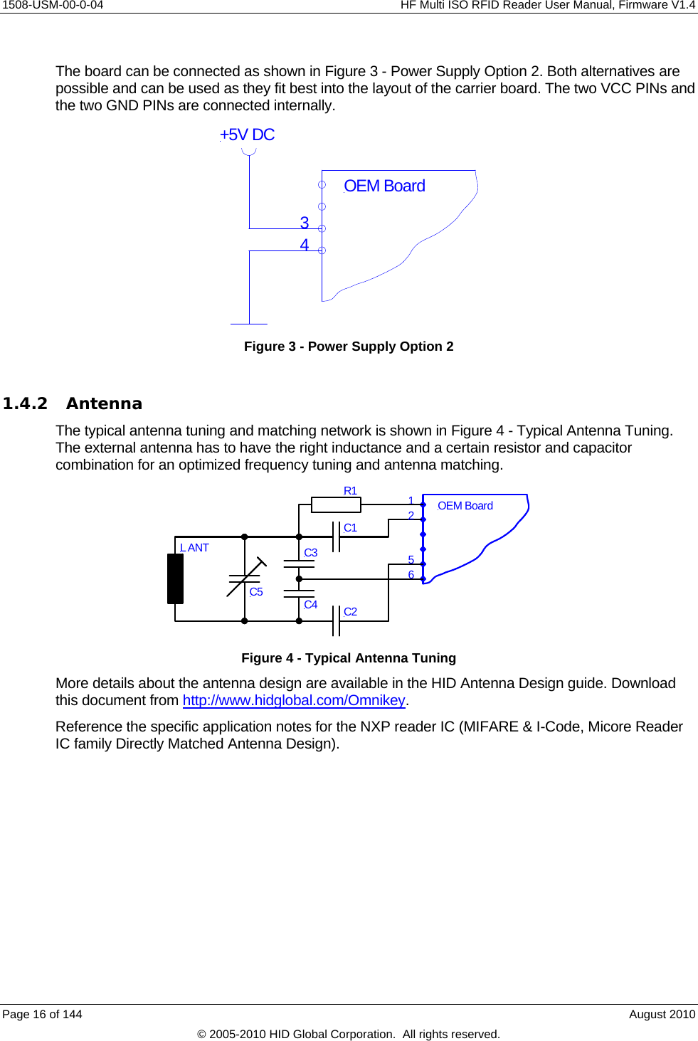
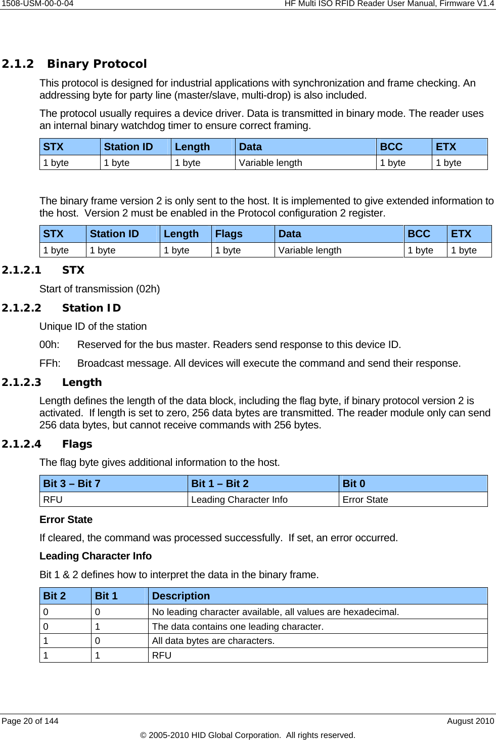
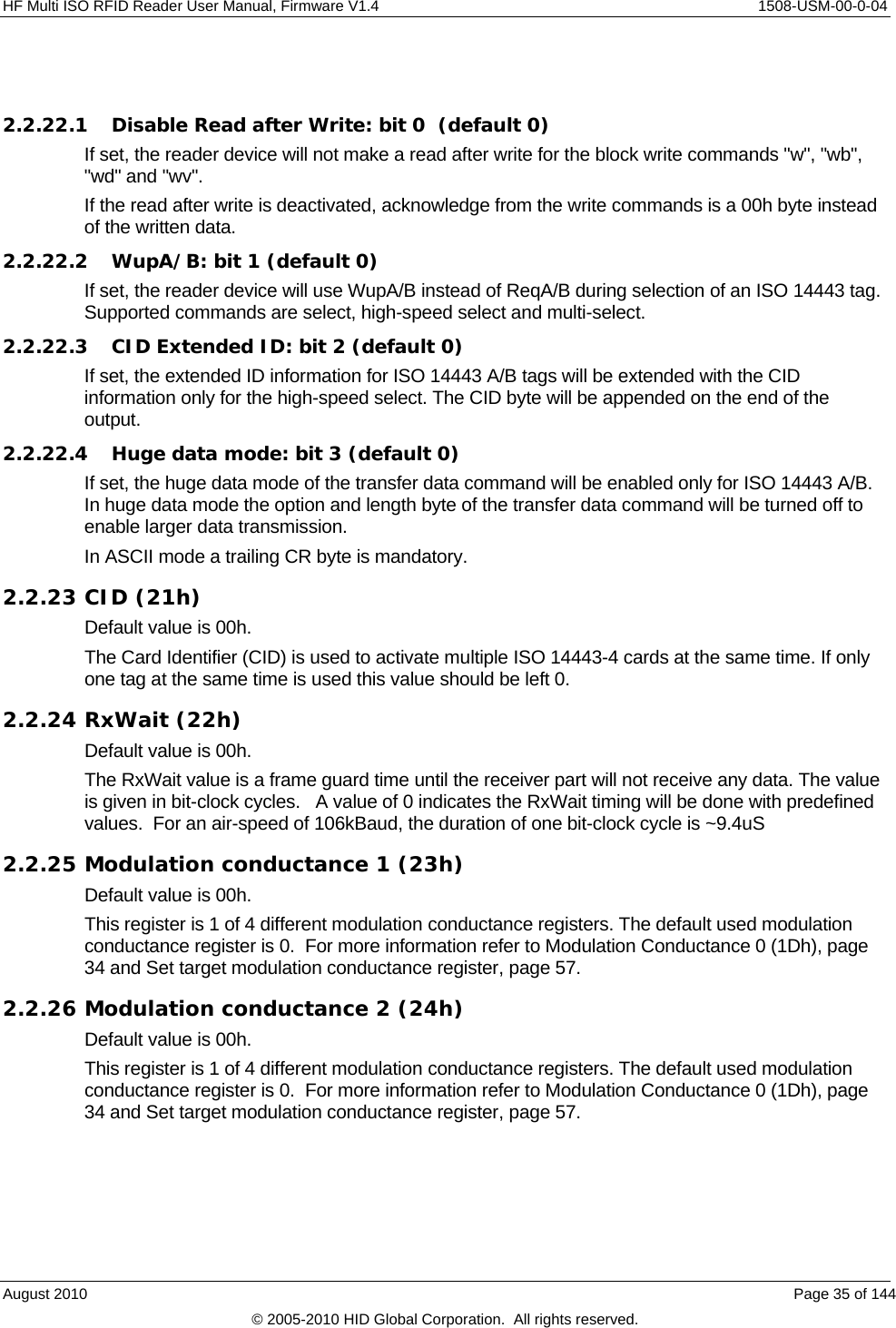
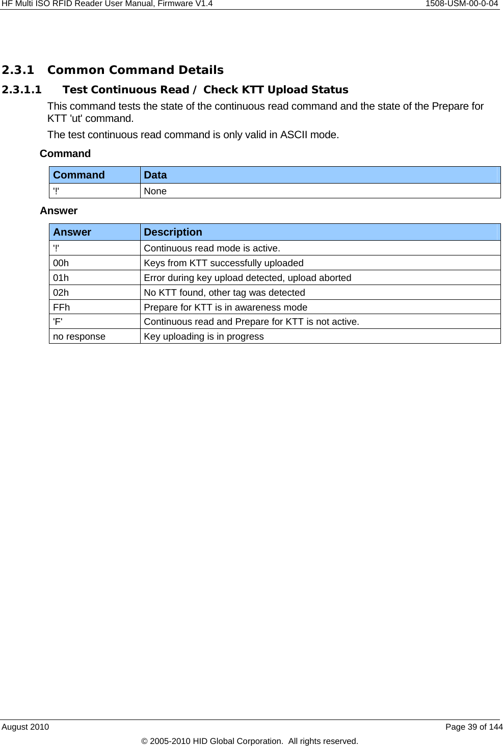
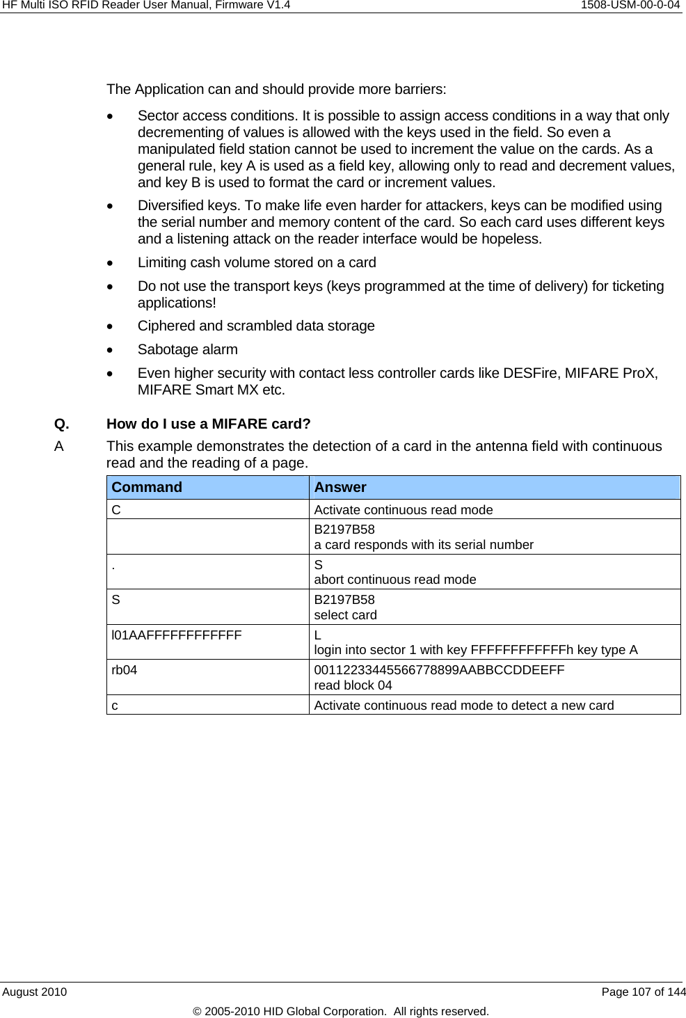
![1508-USM-00-0-04 HF Multi ISO RFID Reader User Manual, Firmware V1.4 Overview Definitions Anti-collision loop An algorithm used to identify and handle a dialogue between a reader and one or more tags in its antenna field. ASCII notation ASCII characters are listed within apostrophes, i.e. ‘x’ means a single x. Hex notation A hexadecimal value is marked with the suffix ‘h’, i.e. A1h has the value A1 hexadecimal. Abbreviations Abbreviation Description AID Application ID ASCII American Standard Code for Information Interchange ATR Answer to Reset ATS Answer to Select AFI Application Family Identifier Block For the MIFARE Standard one block contains 16 bytes CBC Cipher Block Chaining CID Card Identifier (logical card address, ISO 14443-4) CRC Cyclic Redundancy Check DES Data Encryption Standard, for more details about DES refer to [3]. DSFID Data storage format identifier EDC Error Detection Code EGT Extra Guard Time EOF End of Frame ETU Elementary time unit Hex / xxh Value in Hexadecimal notation I-block Information block KTT Key Transfer Transponder LSB Least Significant Bit or Byte MSB Most Significant Bit or Byte NAD Node Address (ISO 14443-4) OSI Open System Interconnection OTP One time programmable PCB Protocol Control Byte (ISO 14443-4) PCON Protocol Configuration byte of the reader PPS Protocol and Parameter Selection RATS Request for Answer to Select Page 8 of 144 August 2010 © 2005-2010 HID Global Corporation. All rights reserved.](https://usermanual.wiki/HID-Global/5553/User-Guide-1322038-Page-8.png)
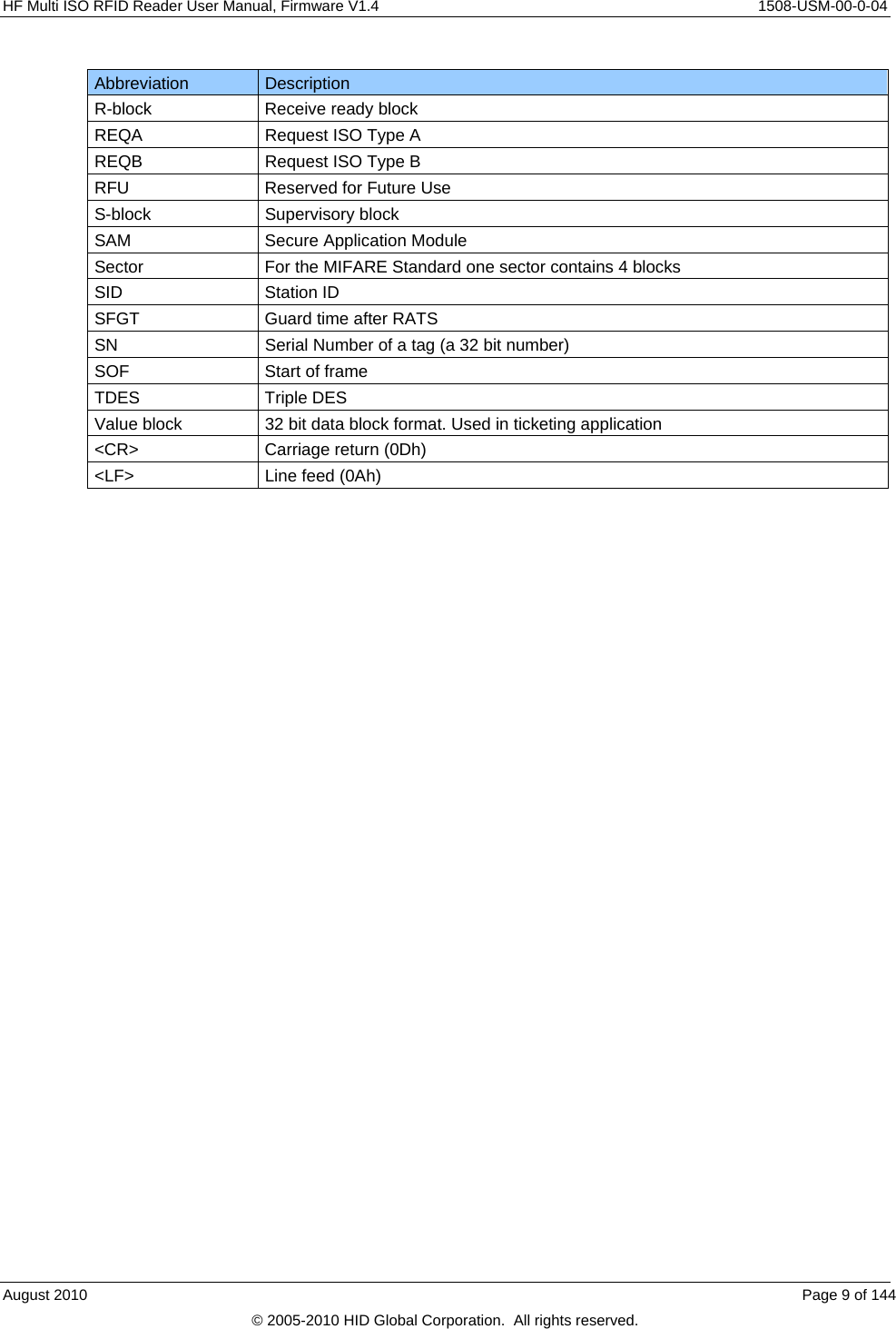
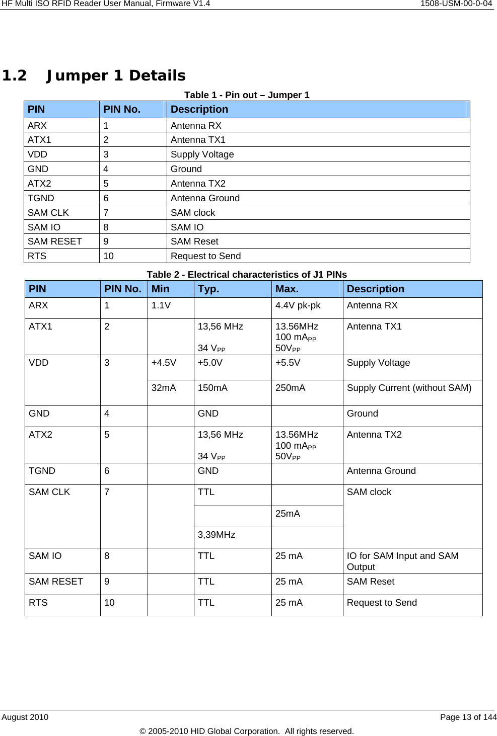
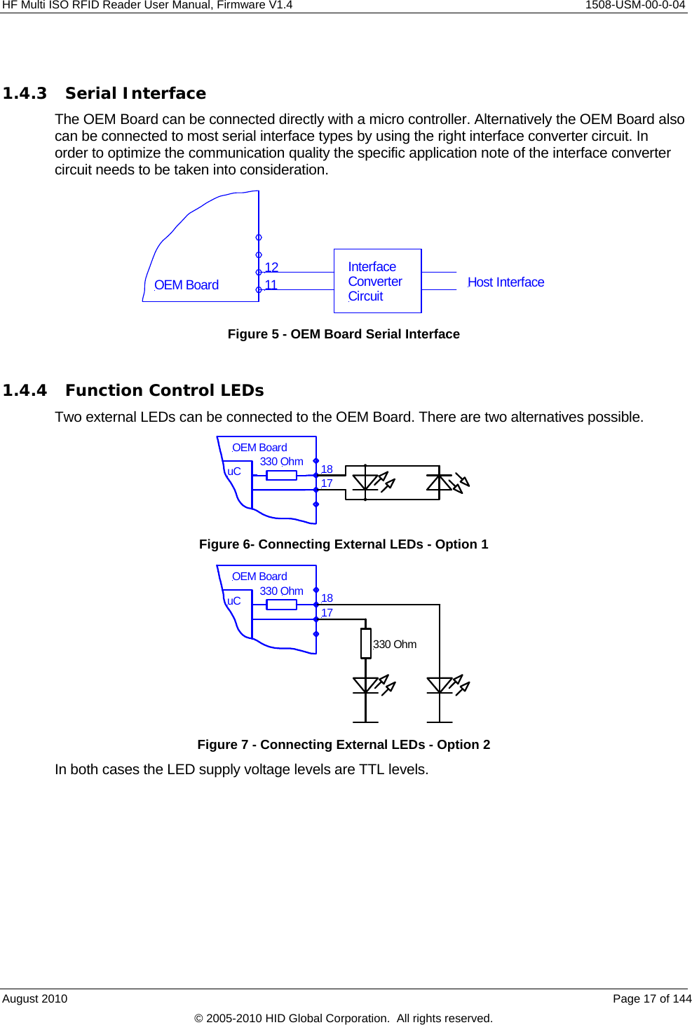
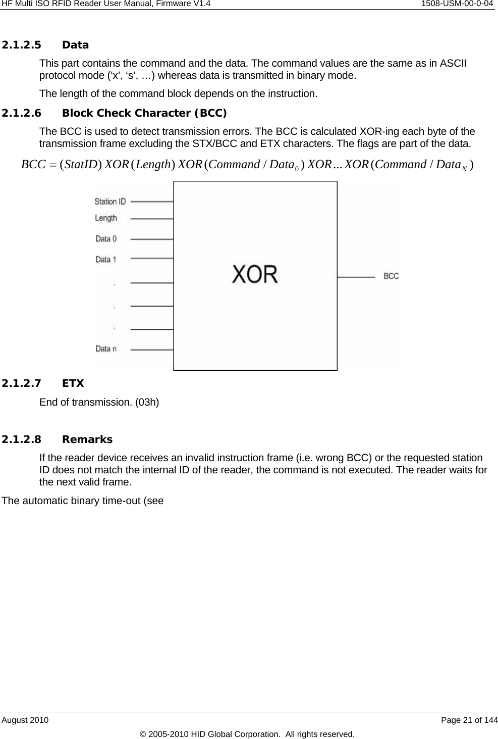
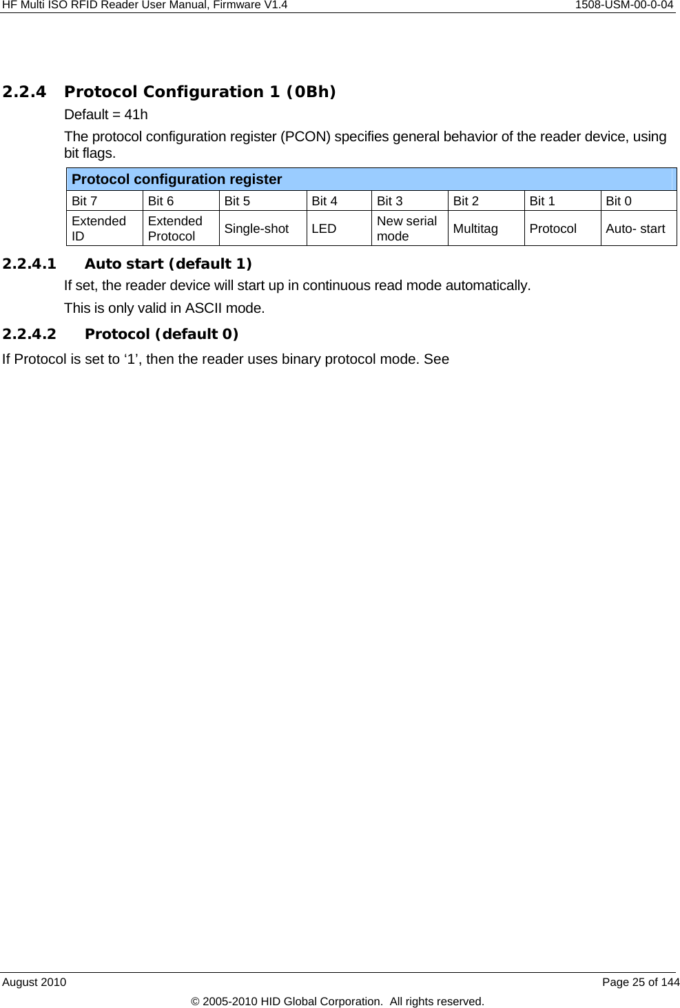
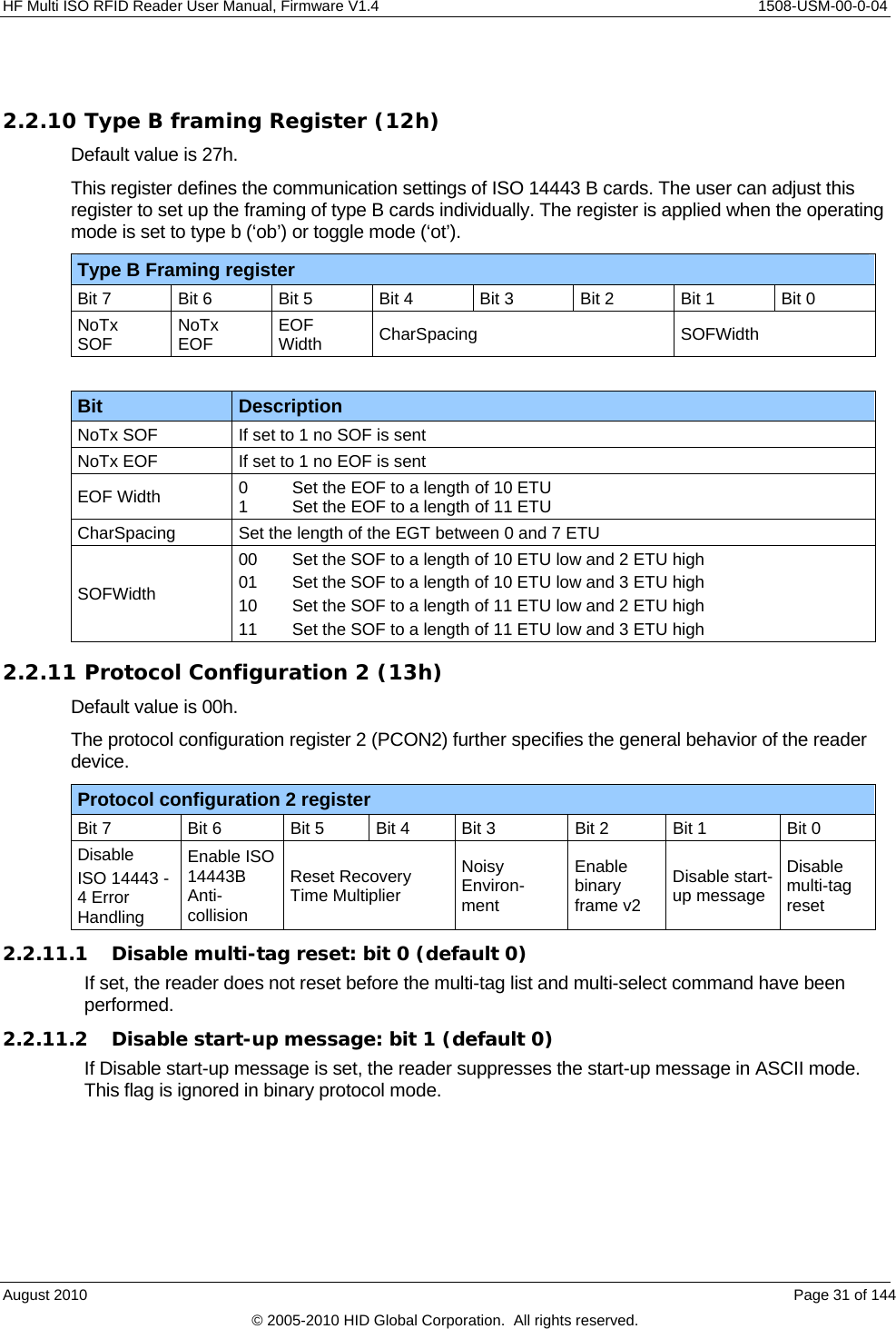
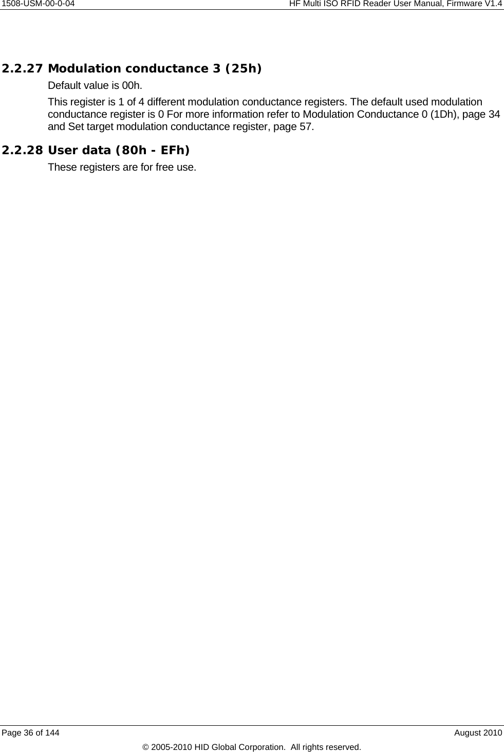
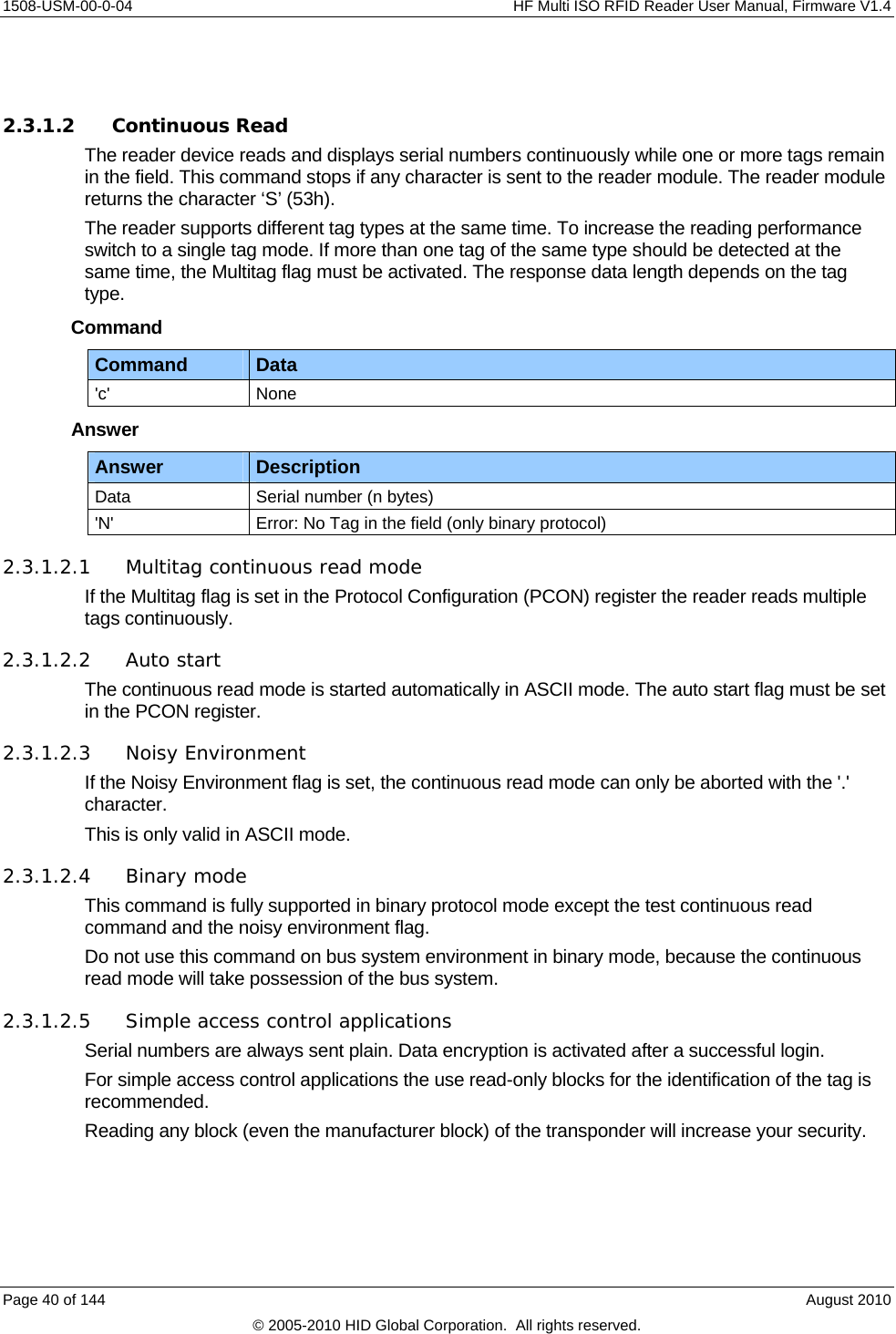
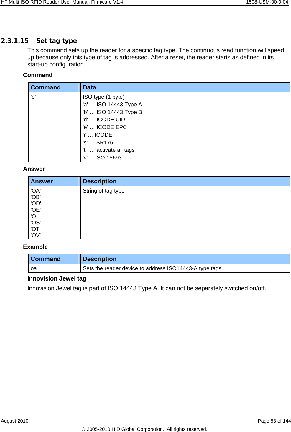
![HF Multi ISO RFID Reader User Manual, Firmware V1.4 1508-USM-00-0-04 2.2 Register Set The reader has several system registers used for customization purposes. These registers are stored in its non-volatile EEPROM. The reader accepts changes to these settings only during the start-up phase. [See Write EEPROM, page 68] Some of the system registers are organized such that each of the 8 bits is an on-off selection for a feature. These are referred to as Flags. [See Set Configuration Flags, page 54] Clearing all RFU bits is recommended in order to guarantee compatibility with future releases. In addition, direct changes to some of these system registers may be made at any time, with immediate effect, but these changes are NOT stored in EEPROM and thus are lost when the reader powers down. [See Set Configuration Flags, page 54 and Set Configuration Register page 56] These ‘on-the-fly’ changes are mapped onto the EEPROM ‘registers’ or memory locations and do not necessarily carry the same ‘register’ values. The reader can store up to 32 authentication keys internally to login standard MIFARE cards. An additional 32 keys can be stored for DESFire authentication. All keys are read only and cannot be accessed through the interface lines. 2.2.1 EEPROM Memory Organization Register Description 00h … 04h Unique device ID; read only 05h … 09h Administrative data; read only 0Ah Station ID 0Bh Protocol configuration 1 0Ch Baud rate 0Dh Command Guard Time 0Eh Operation Mode 0Fh Single shot time-out value 10h TMR low * 11h TMR high * 12h Type B framing * 13h Protocol configuration 2 14h Reset Off Time 15h Reset Recovery Time 16h Application Family Identifier 17h ISO 14443A Selection Time-out 18h ISO 14443B Selection Time-out 19h SR176 Selection Time-out 1Ah ISO 15693 Selection Time-out 1Bh Protocol configuration 3 1Ch Page Start 1Dh Modulation conductance 0 (Type B and SR176. Also ISO15693 if set to 10% modulation) 1Eh Threshold August 2010 Page 23 of 144 © 2005-2010 HID Global Corporation. All rights reserved.](https://usermanual.wiki/HID-Global/5553/User-Guide-1322038-Page-23.png)
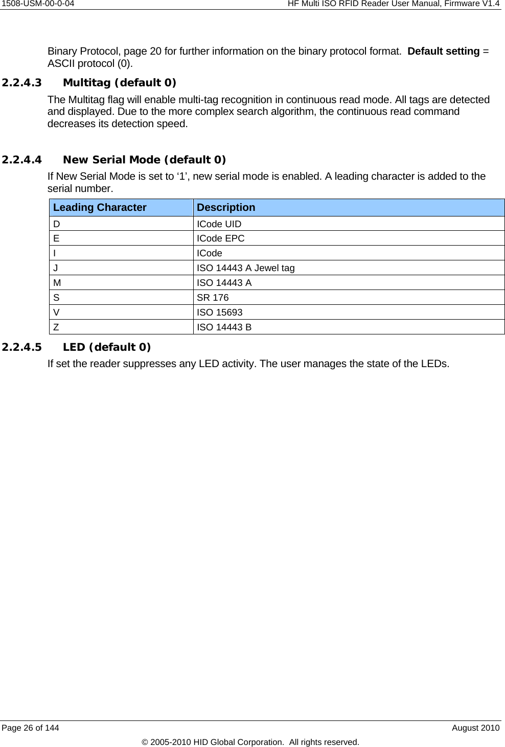
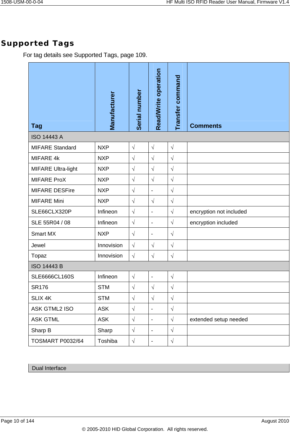
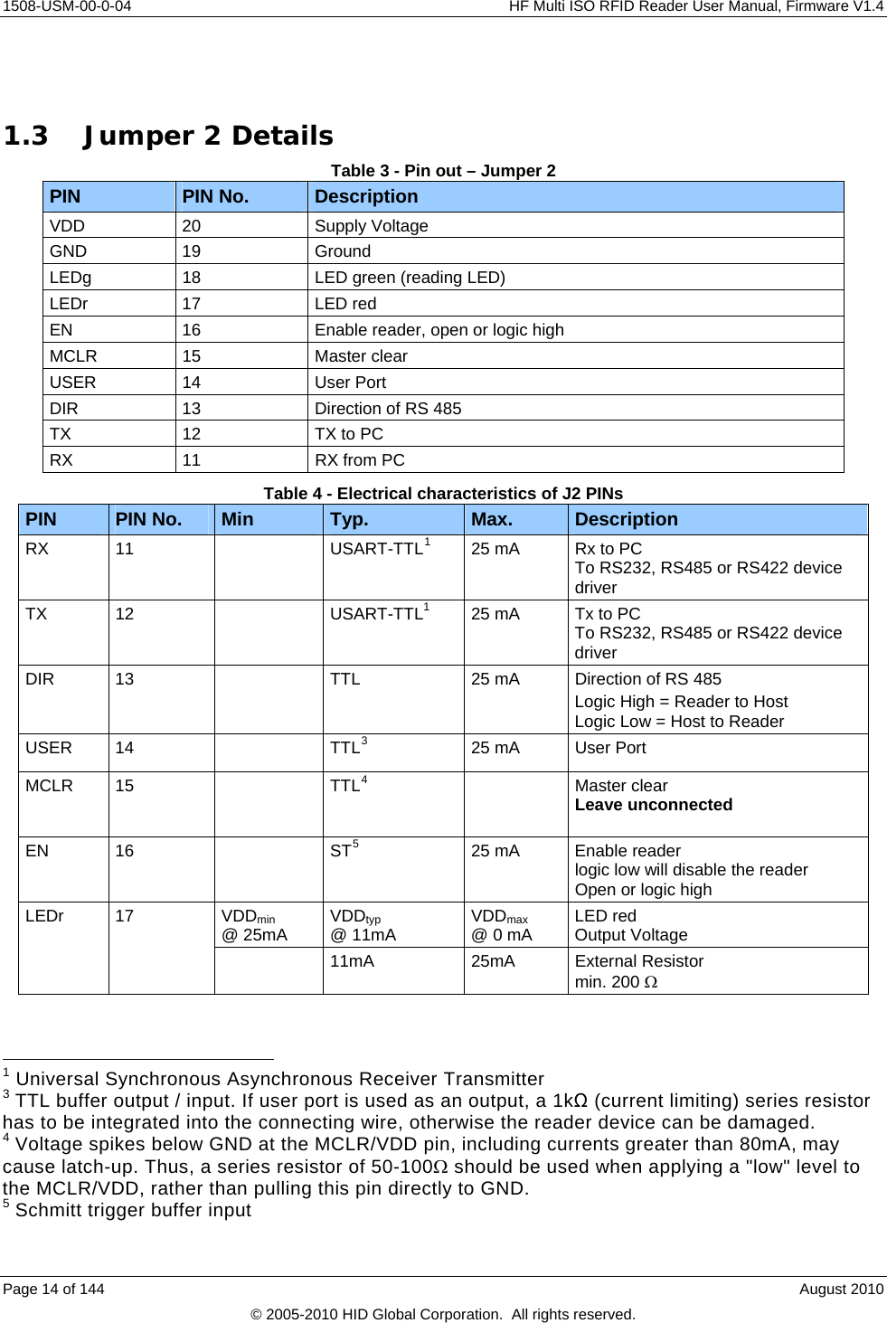
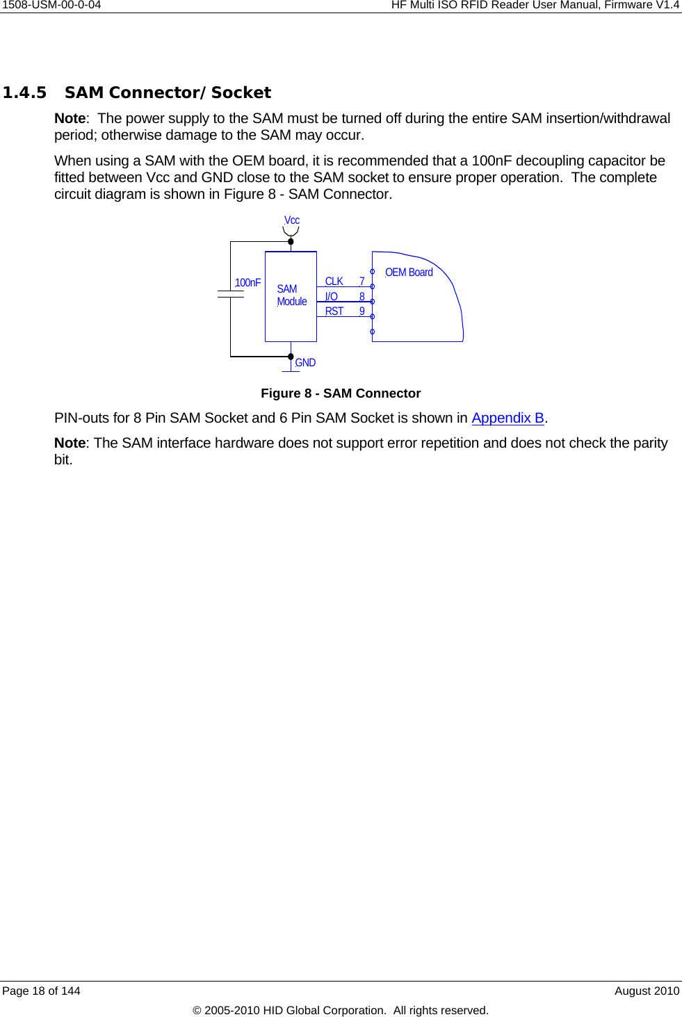
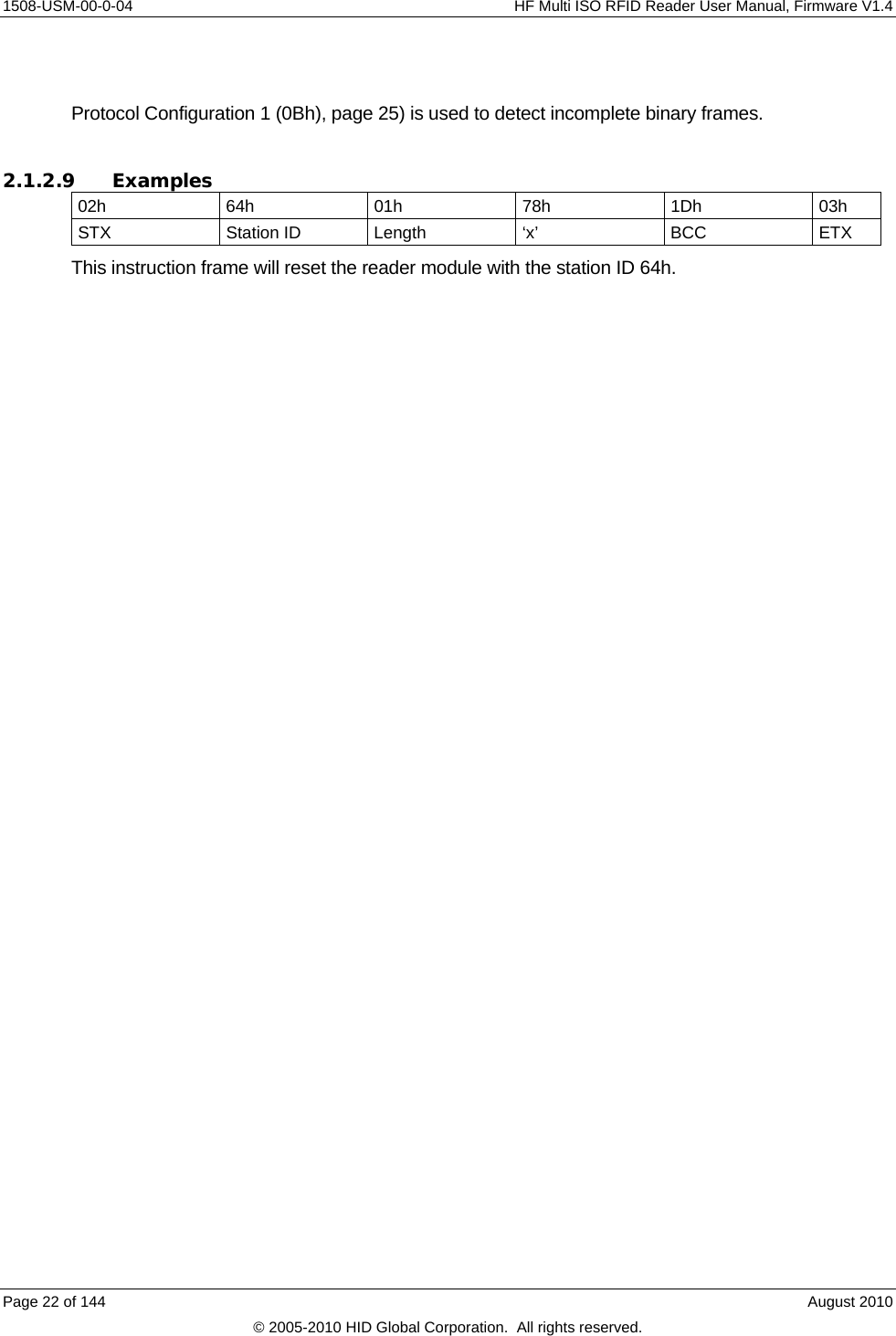
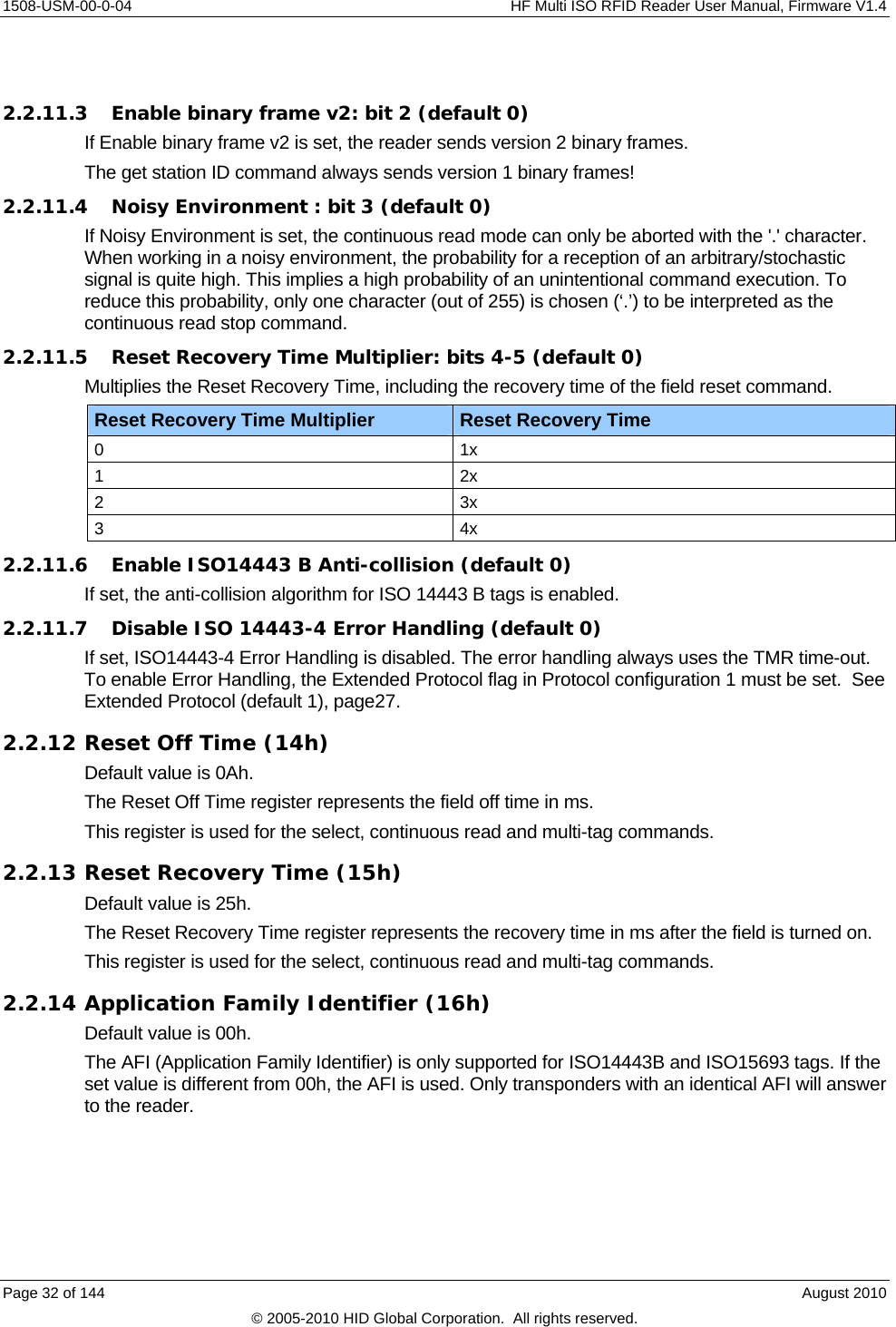
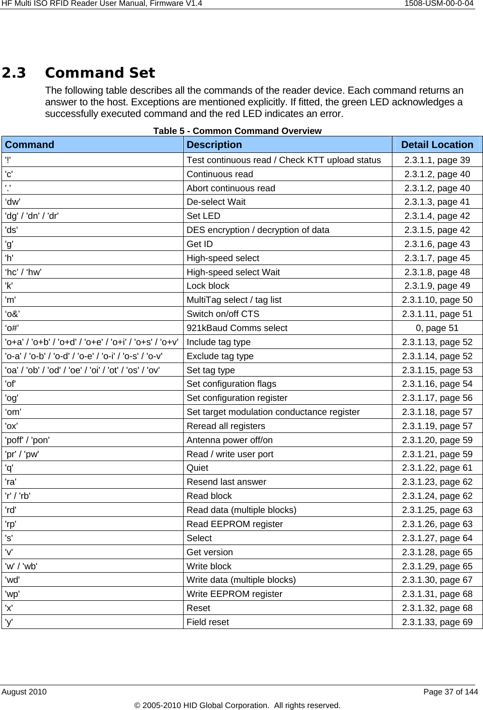
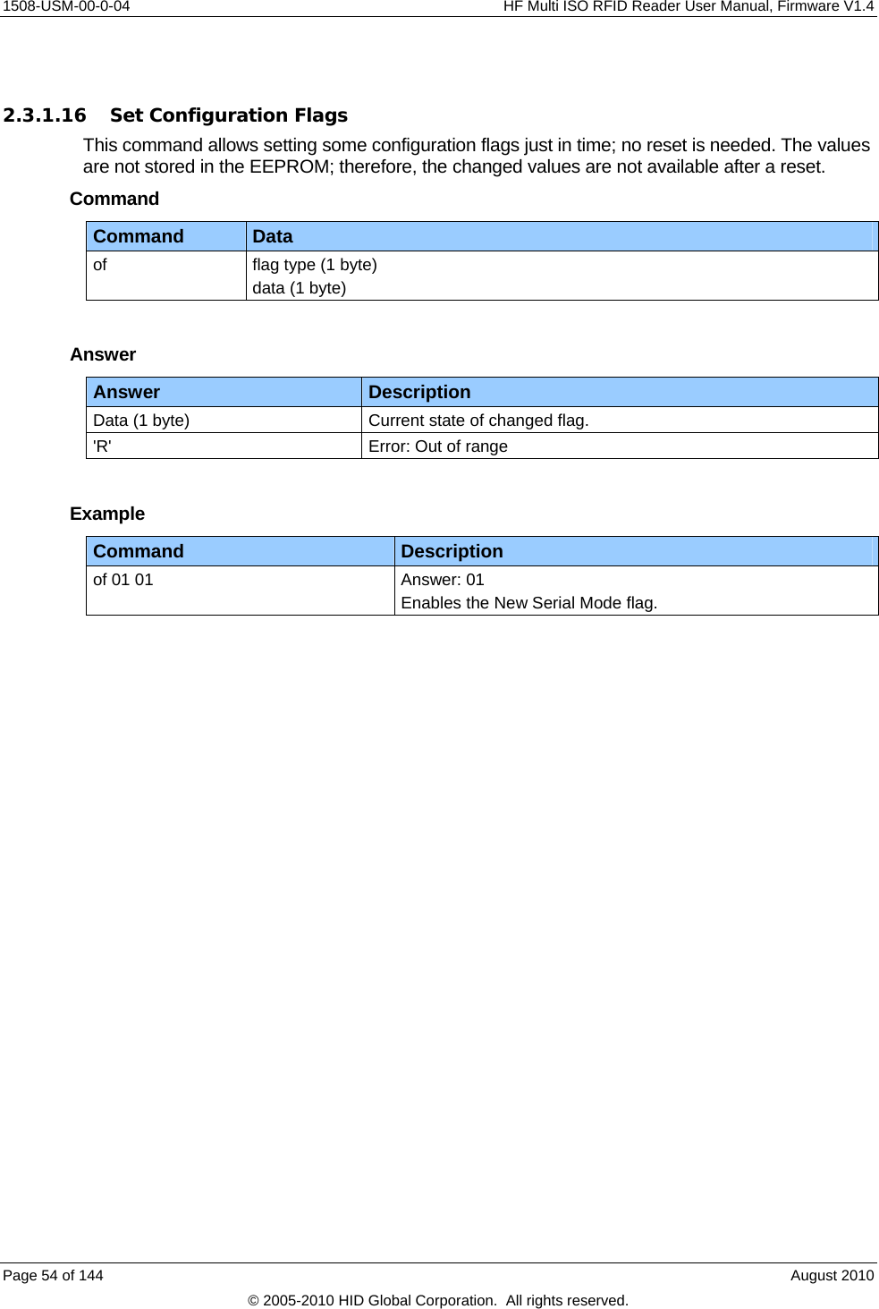
![HF Multi ISO RFID Reader User Manual, Firmware V1.4 1508-USM-00-0-04 2.2.4.6 Single Shot (default 0) If Single Shot is set, the reader displays the serial number of a tag in continuous read mode once within a specified time-out. The time-out is defined at EEPROM register 0Fh. The delay time can be adjusted stepwise in 100ms steps. 00h indicates no delay and FFh indicates infinite delay. Note: The delay precision depends on reset off and reset recovery time. 2.2.4.7 Extended Protocol (default 1) If Extended Protocol is set, the transfer data telegram command supports ISO14443-4 and automatically process the WTX and chaining for smaller frames. This flag has to be set to enable 14443-4 error handling – see Extended Protocol (default 1), page 27. If sending ISO 14443-3 commands this flag has to be switched off. The transfer data telegram command is only supported in normal mode, not in transmit / receive mode. 2.2.4.8 Extend ID (default 0) If the Extend ID is set, the reader extends the serial number with additional information. ISO 14443 A tags Tag type / ReqA Serial number [SAK] 1 byte / 2 bytes 4 / 7 / 10 bytes 1 byte Tag type / ReqA Serial number [SAK] ATS Used Speed [CID] 1 byte / 2 bytes 4 / 7 / 10 bytes 1 byte n bytes 1 byte 1 byte The tag type byte indicates the type of cascade level. Tag type Description 00h Cascade level 1 transponder 01h Cascade level 2 transponder 02h Cascade level 3 transponder ISO 14443 B tags Serial number Application data Protocol info MBLI/CID 4 bytes 4 bytes 3 bytes 1 byte Serial number Application data Protocol info MBLI / CID Used Speed [CID] 4 bytes 4 bytes 3 bytes 1 byte 1 byte 1 byte For detailed description of Application Data, Protocol Info and MBLI/CID, refer to the ISO 14443 documentation [1]. August 2010 Page 27 of 144 © 2005-2010 HID Global Corporation. All rights reserved.](https://usermanual.wiki/HID-Global/5553/User-Guide-1322038-Page-27.png)
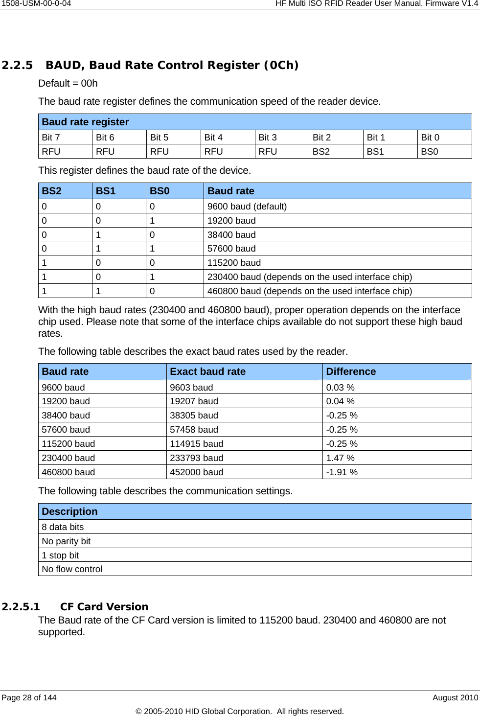
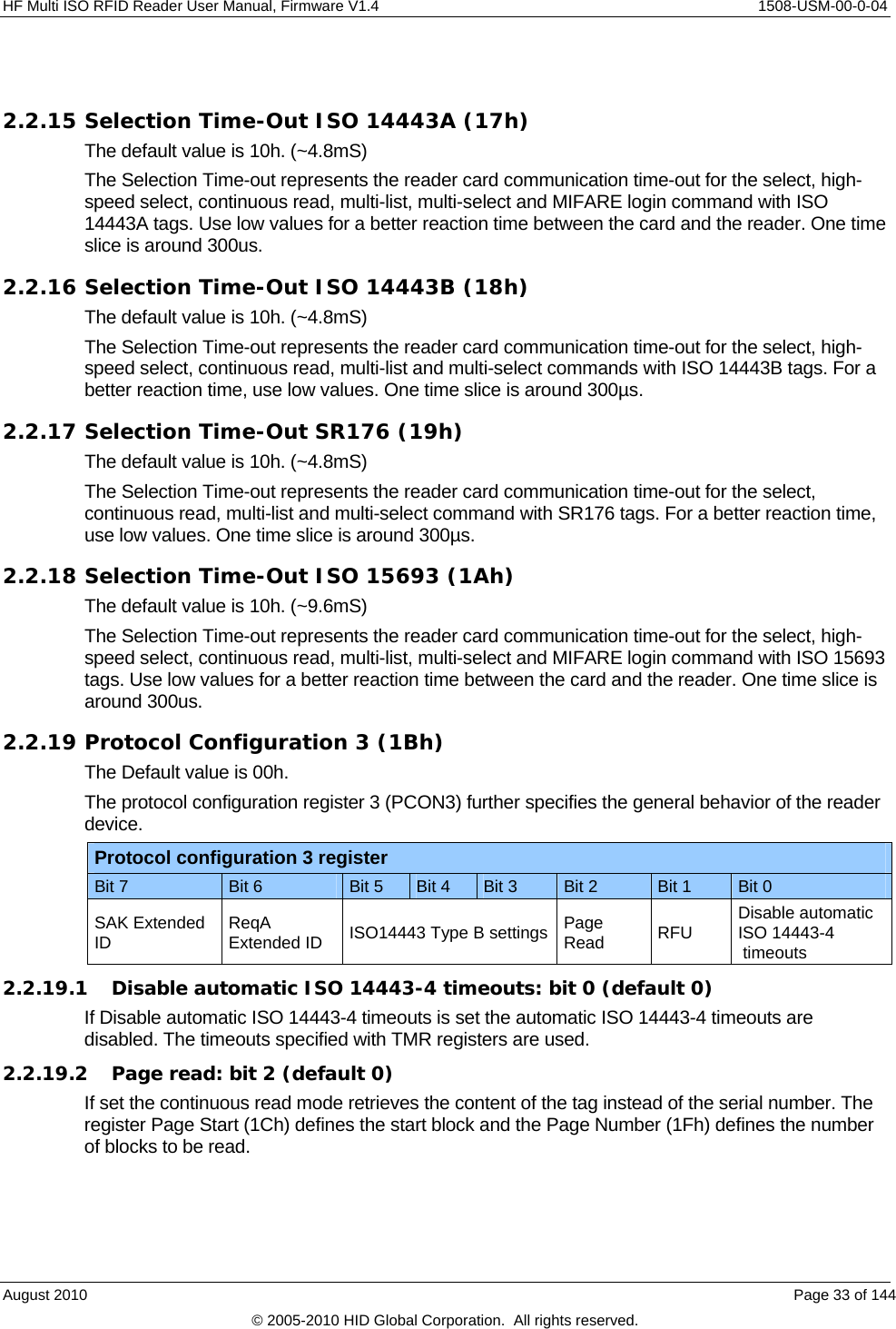
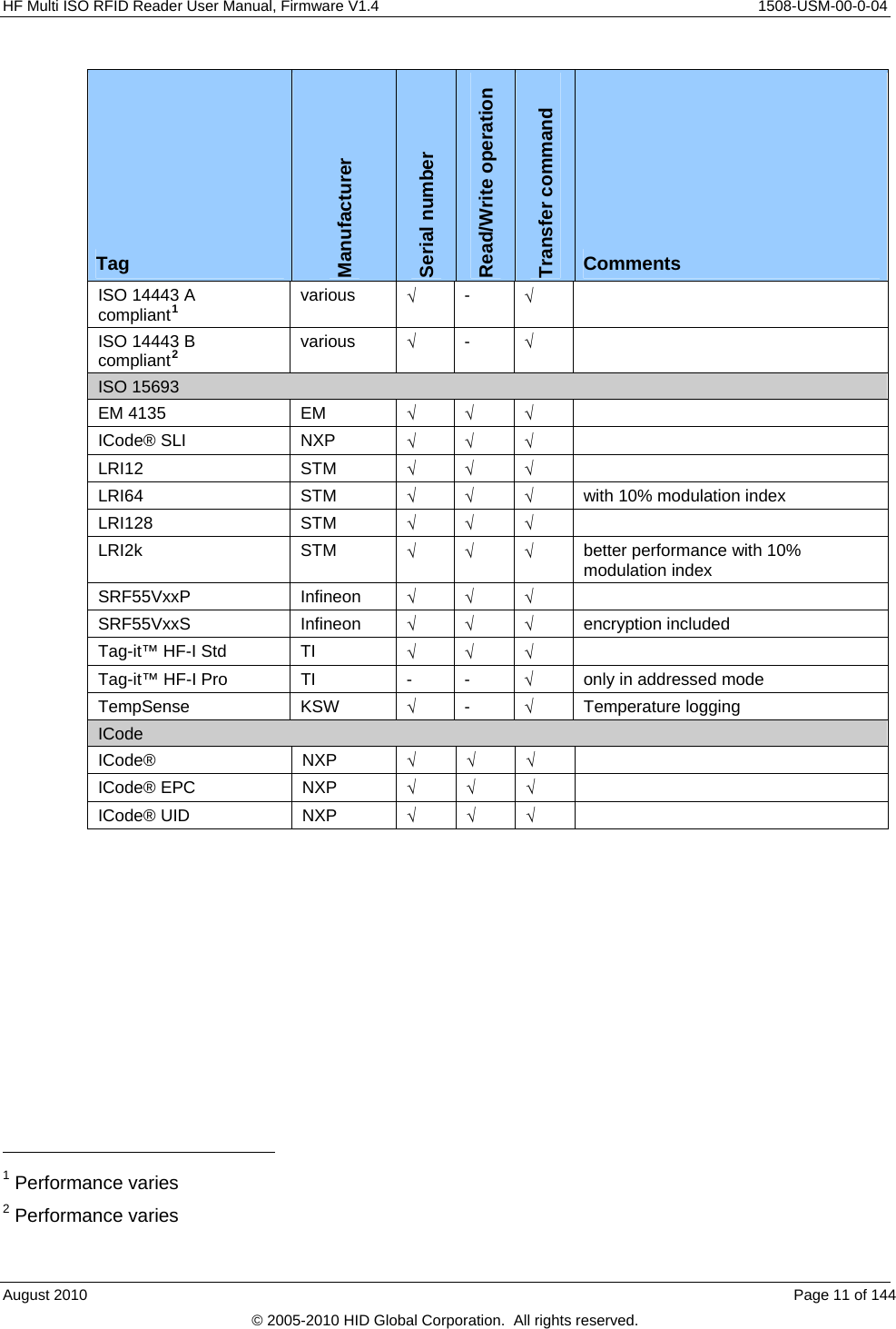
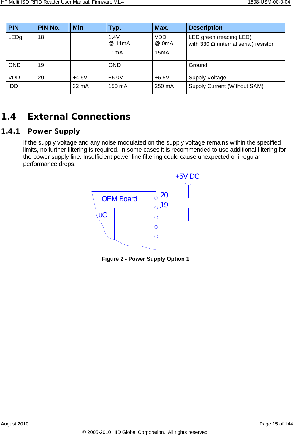
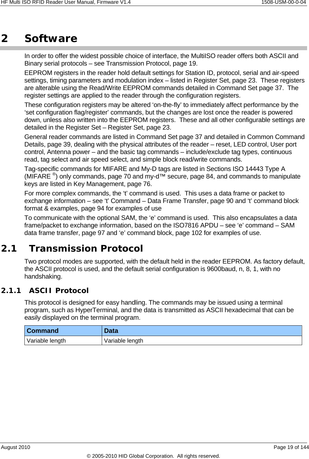
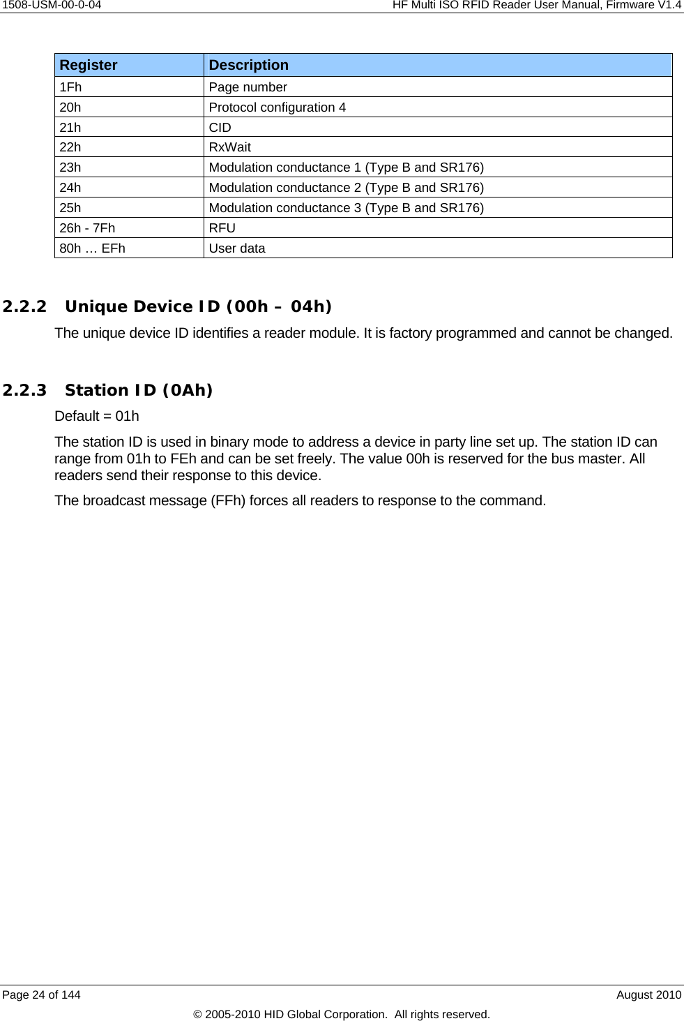
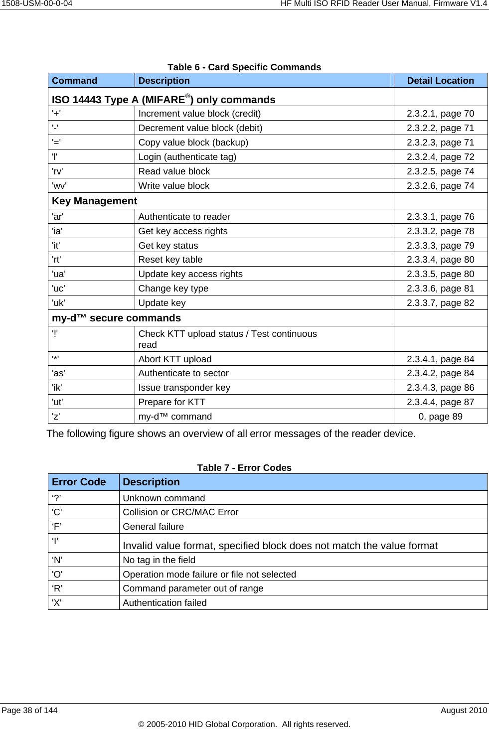
![1508-USM-00-0-04 HF Multi ISO RFID Reader User Manual, Firmware V1.4 2.2.19.3 ISO14443 Type B Rx frame COM settings: bits 3-5 (default 00h) The bits 3 - 5 of this register define the communication settings of ISO 14443 B cards for the receiving frame. Protocol Register 3: Bit 3 – 5 Bit 5 Bit 4 Bit 3 NoRxEOF NoRxEGT NoRxSOF Bit Description NoRxSOF If set to 1 a missing SOF of the received data frame will be ignored. NoRxEGT If set to 1 a too short or too long EGT of the received frame will be ignored. NoRxEOF If set to 1 a missing EOF of the received data frame will be ignored. 2.2.19.4 ReqA Extended ID: bit 6 (default 0) If set the Extended ID information for ISO14443 A tags replaces the cascade level information (1 byte) with Request A answer (2 bytes). 2.2.19.5 SAK Extended ID: bit 7 (default 0) If set the Extended ID information for ISO 14443 A tags will include the SAK byte behind the serial number. 2.2.20 Modulation Conductance 0 (1Dh) Default value is 05h. The modulation defines the conductance of the output driver for the ISO 14443 B and SR176 tags modulation time. If modulation is set to 10%, also include ISO15693 tags. Use this to regulate the modulation index. Note that the conductance values are not linear! For further information, refer to the NXP documentation. [6] 2.2.21 Threshold (1Eh) Default value is EBh The higher nibble of the Threshold register defines the minimum accepted signal strength at the decoder input. The lower nibble of the Threshold register defines the collision level. For further information, refer to the NXP documentation. [6] 2.2.22 Protocol Configuration 4 (20h) Default value is 00h. The protocol configuration register (PCON4) specifies general behavior of the reader device. Protocol configuration 4 register Bit 7 Bit 6 Bit 5 Bit 4 Bit 3 Bit 2 Bit 1 Bit 0 RFU RFU RFU RFU Huge data mode CID Extended ID Disable Read after Write WupA/B Page 34 of 144 August 2010 © 2005-2010 HID Global Corporation. All rights reserved.](https://usermanual.wiki/HID-Global/5553/User-Guide-1322038-Page-34.png)
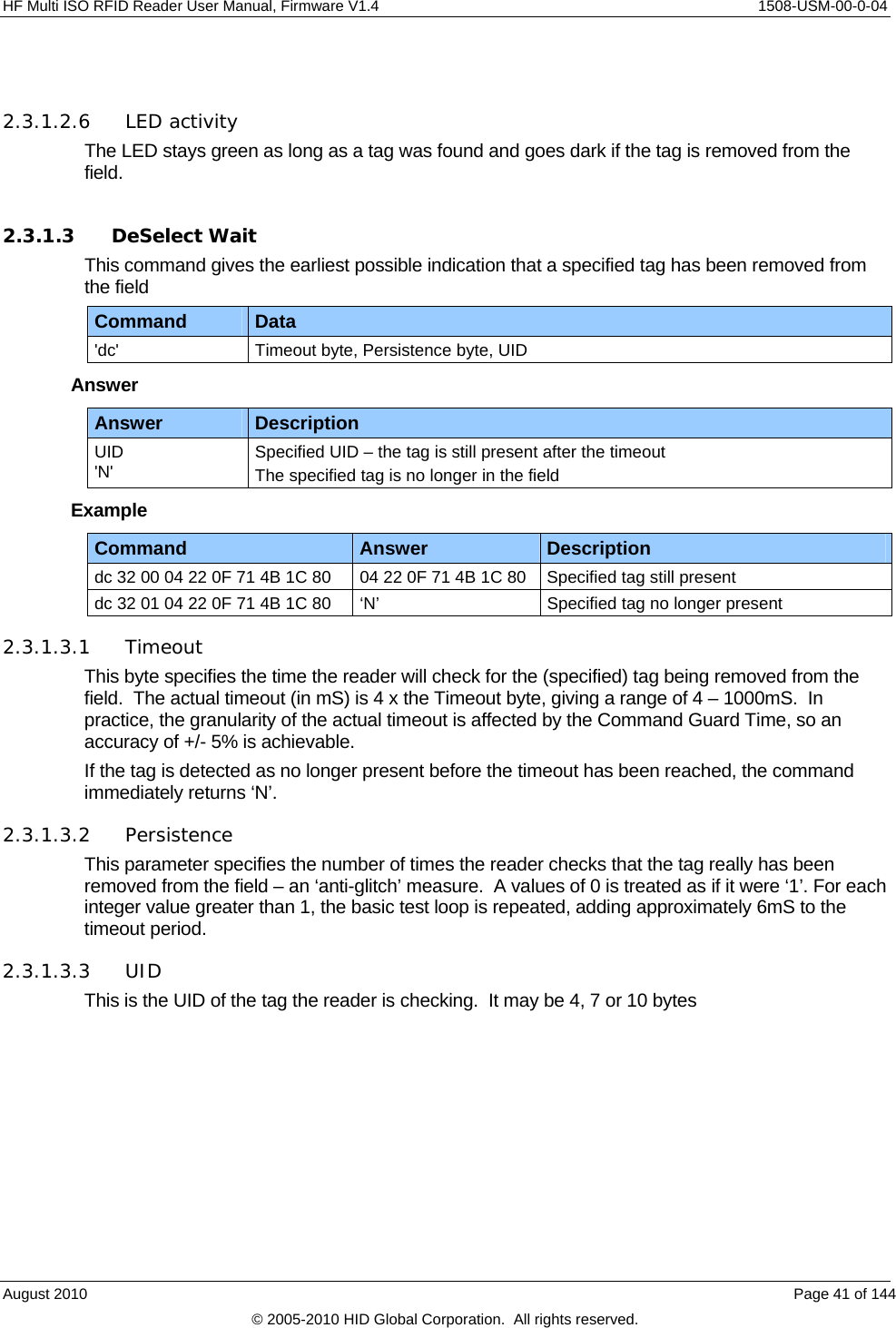
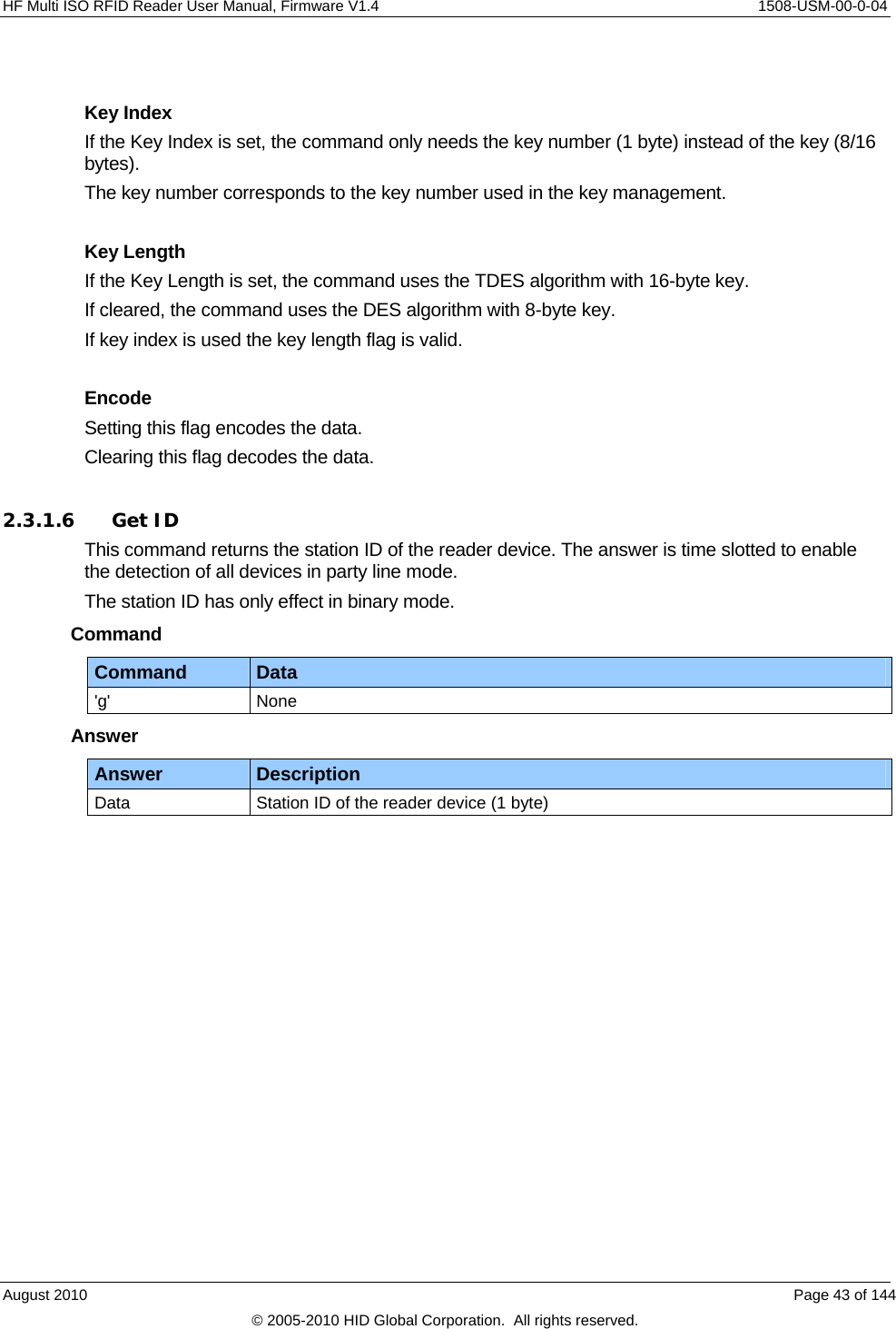
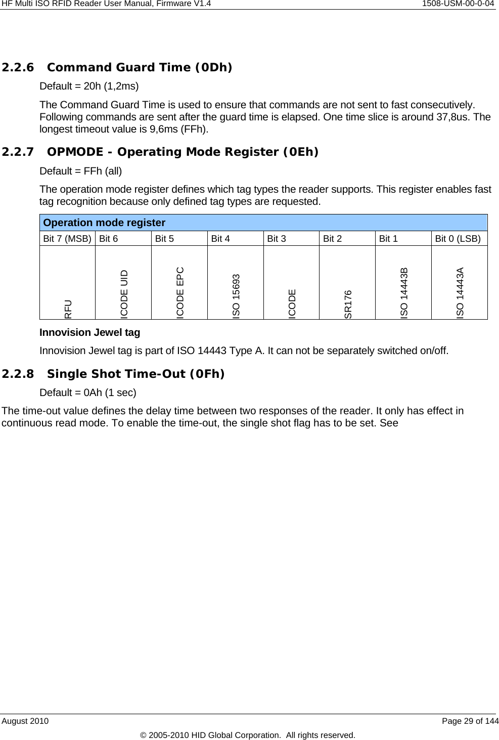
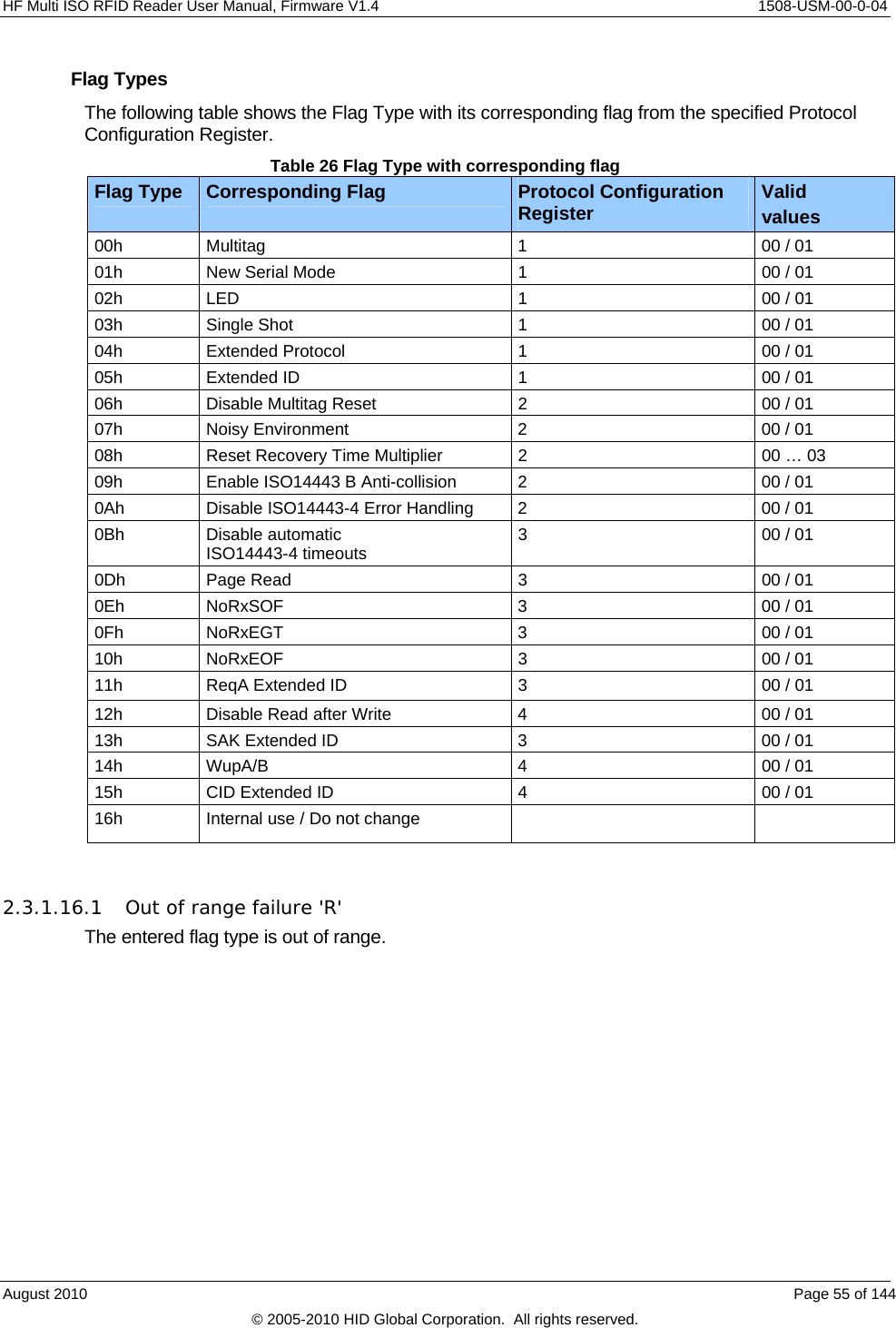
![1508-USM-00-0-04 HF Multi ISO RFID Reader User Manual, Firmware V1.4 2.3.1.6.1 Time slotted answer In party line mode, more than one reader can be used simultaneously. The time slotted answer allows separating in time the answers from all connected devices. The station ID is used to determine the correct time slot. The reader supports up to 254 unique time slots. The following formula calculates the duration of one time slot (only one baud rate is supported per party line): 6*10][0BaudratesT The following figure shows the timing diagram of time slotted answers. Timeslot 0 1 2 3 4 5 … 252 253 254 T0 T1 T2 T3 T4 T5 T252 T253 T254 HOST 'g' Reader (01) 01 Reader (03) 03 Reader (04) 04 Reader (254) 2542.3.1.6.2 Binary Protocol Version 2 This command never sends version 2 binary frames. Page 44 of 144 August 2010 © 2005-2010 HID Global Corporation. All rights reserved.](https://usermanual.wiki/HID-Global/5553/User-Guide-1322038-Page-44.png)
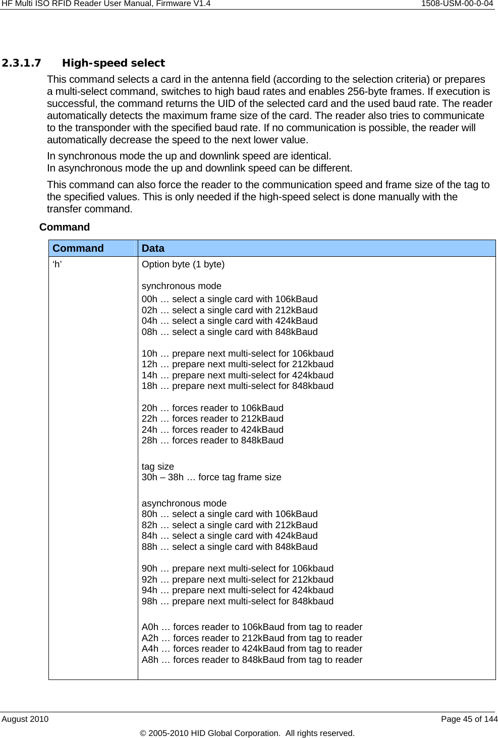
![1508-USM-00-0-04 HF Multi ISO RFID Reader User Manual, Firmware V1.4 Command Data B0h … forces reader to 106kBaud from reader to tag B2h … forces reader to 212kBaud from reader to tag B4h … forces reader to 424kBaud from reader to tag B8h … forces reader to 848kBaud from reader to tag Answer Answer Description Data (n bytes) + frame size and baud rate (1byte) Serial number + frame size used and baud rate 'F' Error: General failure ‘N’ Error: No Tag in field [addressed tag not present or not responding] Note: If the tag does not support ISO 14443 part 4 F0h will return after serial number instead of used frame size/baud rate. Examples High-speed select Command Description h08 1234567890ABCD84 Select the card with UID 1234567890SABCD. The card supports a 256-byte frame size and 424kBaud on the air interface. High-speed multi-select Command Description h18 m1234567890ABCD<CR> Prepare next multi-select for 848kBd 1234567890ABCD84 Select the card with UID 1234567890SABCD. The card supports a 256-byte frame size and 424kBaud on the air interface. 2.3.1.7.1 Answer from 0xh and 1xh The lower nibble contains the baud rate used for the air interface. Baud Rate Description x0 106kBaud x2 212kBaud x4 424kBaud x8 848kBaud The higher nibble contains the frame size used for the air interface. Frame Size Description 0x 16 Bytes 1x 24 Bytes 2x 32 Bytes Page 46 of 144 August 2010 © 2005-2010 HID Global Corporation. All rights reserved.](https://usermanual.wiki/HID-Global/5553/User-Guide-1322038-Page-46.png)
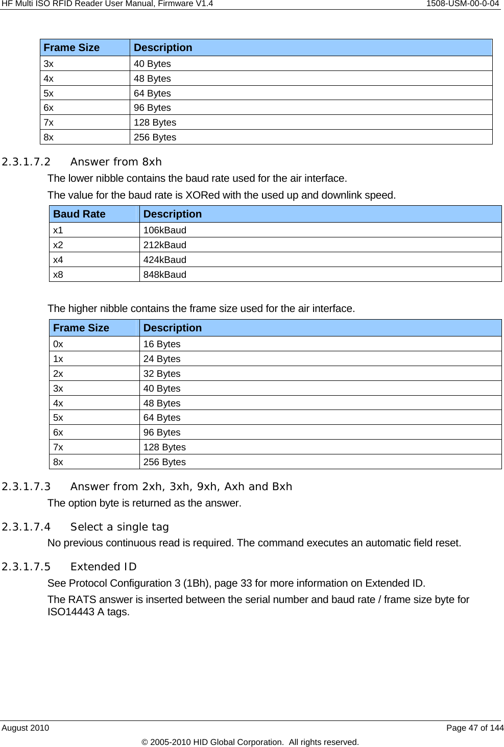
![1508-USM-00-0-04 HF Multi ISO RFID Reader User Manual, Firmware V1.4 2.3.1.7.6 Multiple tags This command with parameter 1xh prepares the next multi-select command as a high-speed select. Any other command will disable the preparation. 2.3.1.7.7 RATS Guard Time SFGT A high-speed select with parameters 0xh and 1xh automatically waits the SFGT guard time received from the tag before sending the PPS command. 2.3.1.8 High Speed Select Wait There are two command variants – ‘hc’ and ‘hw’. If one or more tag(s) are present, return both the selected UID and in the case of multiple tags, also report that a collision was detected, reducing the host processing overhead. The ‘hw’ command additionally allows specific Reset off and Reset recovery times to be set, without altering the Register values, and will search tags for a specified time, further reducing the host processing overhead. Command Command Data ‘hc’ Option byte ‘hw’ Option byte, Reset Off time, Reset Recovery time, Wait time Answer Answer Description Data (n bytes) + frame size and baud rate (1byte) + collision flag Serial number + frame size used and baud rate [+ collision flag] 'F' Error: General failure ‘N’ Error: No tag in field [addressed tag not present or not responding] Note: If the selected tag does not support ISO 14443 part 4, instead of the used frame size/baud rate byte being returned after the UID, the command will return byte F0h. Examples Command Description hc88 04 91 DF E9 F1 02 80 F0 08 Responding tag doesn’t support ISO14443-4 – hence FO – and multiple cards were detected – 08 04 22 0F 14 4B 1C 80 58 Responding tag supports a 64-byte frame size and 848kBaud on the air interface - 58 hc88 04 91 DF E9 F1 02 80 F0 08 Responding tag doesn’t support ISO14443-4 – hence FO – and multiple cards were detected – 08 hw88 0A 20 32 04 22 47 14 4B 1C 80 84 Responding tag supports a 256-byte frame size and 424kBaud on the air interface – 84 hw88 0A 20 32 hw88 0A 20 32 ‘N’ After a reset/recovery period, the reader searched for tags for 200mS (4 * 32h). None found. Page 48 of 144 August 2010 © 2005-2010 HID Global Corporation. All rights reserved.](https://usermanual.wiki/HID-Global/5553/User-Guide-1322038-Page-48.png)
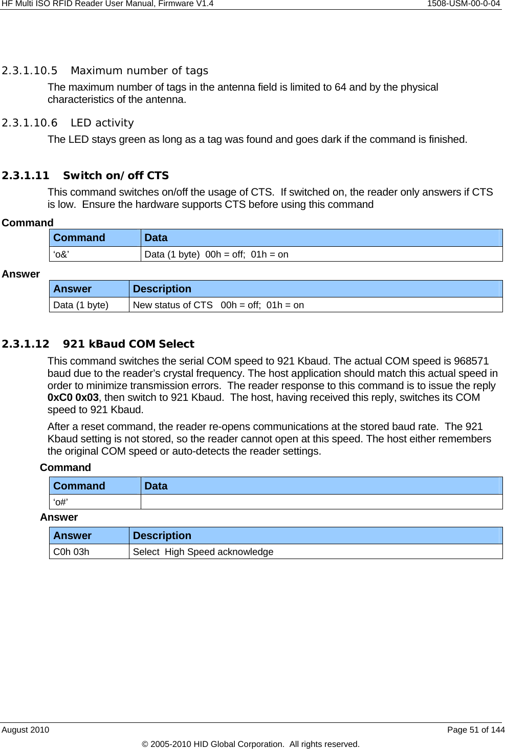
![HF Multi ISO RFID Reader User Manual, Firmware V1.4 1508-USM-00-0-04 Option See High-speed select, page 45 for a full description of this byte. Reset Off The length of time the field is switched off Reset Recovery The time for the field to stabilize after being switched on Wait The length of time in mS * 4 the reader will search for tags (19h = 25 * 4 = 100mS) Note: A zero wait time is not supported by the reader. 2.3.1.9 Lock Block This command locks a block permanently. Only SR176 and ISO 15693 tags are supported. Command Command Data 'k' Block address (1 byte) Answer Answer Description Data 'K' + page address 'F' Error: Lock failure 'N' Error: No tag in field [addressed tag not present or not responding] 'O' Error: Operation mode failure [tag is neither SR176 or ISO 15693 compliant] 'X' Error: Block already locked Example Command Description k05 K05 Lock block 05. 2.3.1.9.1 Apply settings After locking a block permanently, the tag needs to be selected for the settings to apply. August 2010 Page 49 of 144 © 2005-2010 HID Global Corporation. All rights reserved.](https://usermanual.wiki/HID-Global/5553/User-Guide-1322038-Page-49.png)
![1508-USM-00-0-04 HF Multi ISO RFID Reader User Manual, Firmware V1.4 2.3.1.10 Multi-Tag Selection / List This command detects several tags at the same time. It replaces the fast select command ('s') in multiple tag surroundings. The Multi-Tag List command lists all tags with their serial numbers. Use the Multi-Tag Select command to select a single tag. Each tag has to be selected separately. Command Command Data 'm' Serial number (n bytes) <CR> (1 byte) Answer Answer Description Data serial number 'N' Error: No Tag in the field [addressed tag not present or not responding] Example Command Description m<CR> 04E9E700000000 first card 34030F07 second card 02 number of detected tagsm04E9E700000000<CR> Select card with its serial number 2.3.1.10.1 Multi-tag list Sending a <CR> as the first parameter, the reader returns a list of all tags present in the antenna field. In the end the total number of tags detected is returned. 2.3.1.10.2 Reading distance Each card needs a specific amount of power. The reader always provides the same power level. Therefore, the reading distance will decrease if more tags are present. Basically, the reading distance depends on the tag, the antenna and the tuning of the antenna. 2.3.1.10.3 Multi-tag select Using the serial number with <CR> as parameter, the corresponding tag will be selected. High-level interactions can be performed addressing only this card. All other tags remain silent. 2.3.1.10.4 Multi-tag reset The antenna field reset can be deactivated with the Protocol configuration 2 register. By suppressing the antenna field reset, it is possible to detect only new tags in the antenna field. CAUTION: Possibly, ISO 15693 tags are interfered from ISO14443 type B and SR 176 tags. In this case, the ISO 15693 tag always answers on a multi list command even if there was no previous field reset. In this case, deactivate ISO 14443 B and SR 176 tags. Page 50 of 144 August 2010 © 2005-2010 HID Global Corporation. All rights reserved.](https://usermanual.wiki/HID-Global/5553/User-Guide-1322038-Page-50.png)
![1508-USM-00-0-04 HF Multi ISO RFID Reader User Manual, Firmware V1.4 2.3.1.17 Set Configuration Register This command allows setting some configuration registers just in time; no reset is needed. The values are not stored in the EEPROM; therefore the changed values are not available after a reset. Command Command Data Og Register type (1 byte) data (1 byte) Answer Answer Description Data (1 byte) Current state of changed register. 'R' Error: Out of range [entered register value is out of range] Example Command Description og0450 Answer: 50 Sets the Reset Recovery Time to 50h. Register Types The following table shows the Register Type with its corresponding register. Table 8 - Register Type with Corresponding Register Register Type Corresponding Register 00h Single shot time-out value 01h TMR low 02h TMR high 03h Reset Off Time 04h Reset Recovery Time 05h ISO 14443A Selection Time-out 06h ISO 14443B Selection Time-out 07h SR176 Selection Time-out 08h AFI 09h Modulation conductance 0Ah Threshold 0Ch Page Read Start 0Dh Page Read Number 0Eh Command Guard Time 0Fh CID 10h Internal use / Do not change Page 56 of 144 August 2010 © 2005-2010 HID Global Corporation. All rights reserved.](https://usermanual.wiki/HID-Global/5553/User-Guide-1322038-Page-56.png)
![HF Multi ISO RFID Reader User Manual, Firmware V1.4 1508-USM-00-0-04 2.3.1.18 Set target modulation conductance register This command allows switching to a different modulation conductance register. On startup, modulation conductance register 0 is used. When more than one antenna is used, it may be necessary to use different modulation conductance values for different antennas. Switching registers does not require knowledge of the actual values used. Ensure that Modulation Conductance registers 1-3 are initialized before using this feature. Command Command Data om Target modulation conductance register (1 byte) Valid range 00h – 03h Answer Answer Description Data (2 bytes) Target modulation conductance register (1 byte); register value (1 byte) ‘R’ Error: Out of range [selected register is out of range] 2.3.1.19 Reread all registers This command rereads and applies all register settings. Command Command Data Ox none Answer Answer Description Data (3 bytes) 'X' + new protocol + new baud rate Example Command Description Ox Answer: X0106 binary protocol and 460800 baud active New protocol 00h means ASCII and 01h means binary protocol. New baud rate Values of 00h-06h are valid. For baud rate values refer to August 2010 Page 57 of 144 © 2005-2010 HID Global Corporation. All rights reserved.](https://usermanual.wiki/HID-Global/5553/User-Guide-1322038-Page-57.png)
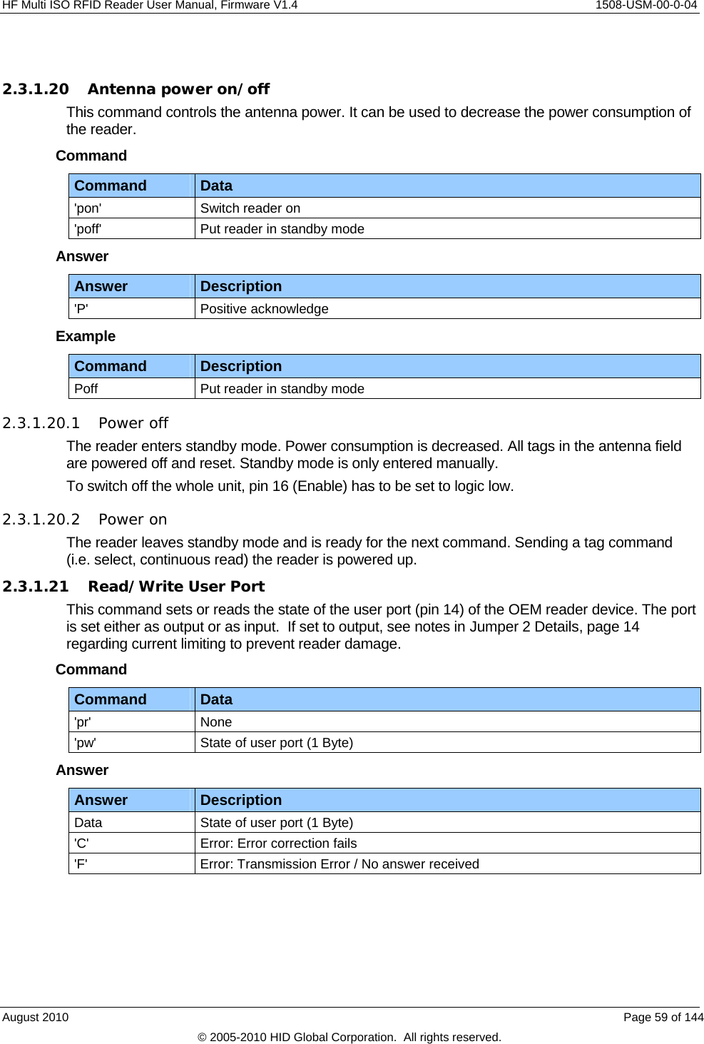
![HF Multi ISO RFID Reader User Manual, Firmware V1.4 1508-USM-00-0-04 After 2ms Guard Time the answer should be received on the User Port otherwise an error is returned. Table 10 - Receiving Serial Data Frame Receive Frame Description Low Start bit Error Bit If set, an error was detected. Data Bit 6 State of the User Port Bit 6 Data Bit 5 State of the User Port Bit 5 Data Bit 4 State of the User Port Bit 4 Data Bit 3 State of the User Port Bit 3 Data Bit 2 State of the User Port Bit 2 Data Bit 1 State of the User Port Bit 1 Data Bit 0 State of the User Port Bit 0 Parity Bit Even Parity Bit High Stop Bit If the Error bit is set or the Parity Bit is not correct, the Write User Port command returns an error code. 2.3.1.22 Quiet This command sets a selected tag into halt state. Only ISO14443 A+B and SR176 tags are supported. Command Command Data 'q' None Answer Answer Description 'Q' Halt state successfully set. 'N' Error: No Tag in the field [addressed tag not present or not responding] 2.3.1.22.1 ISO 14443 Type A With ISO14443-3 Type A tags, the Quiet command always answers with 'Q' because the halt command does not send any acknowledge. In Part 4 a 'Deselect' command will be performed. 2.3.1.22.2 ISO 14443 Type B Some ISO14443 Type B tags do not support this command or do not respond. ‘Quiet’ is an ISO 14443-4 command, so it will work only if the ‘Deselect’ command is supported by the corresponding transponder. 2.3.1.22.3 SR176 With SR176 tags the Quiet command always answer with 'Q' because the completion command does not send any acknowledge. August 2010 Page 61 of 144 © 2005-2010 HID Global Corporation. All rights reserved.](https://usermanual.wiki/HID-Global/5553/User-Guide-1322038-Page-61.png)
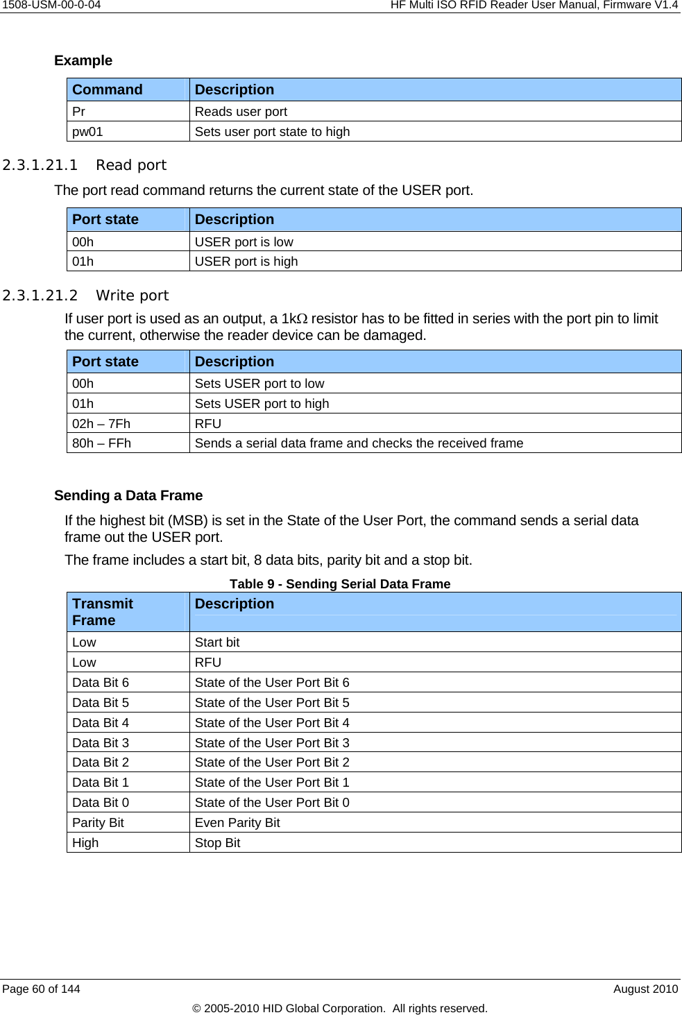
![1508-USM-00-0-04 HF Multi ISO RFID Reader User Manual, Firmware V1.4 2.3.1.23 Resend Last Answer This command resends the last answer from the internal serial buffer of the reader. Command Command Data 'ra' Resend last answer 2.3.1.24 Read block This command reads a data block on a card. The size of the returned data depends on the tag used. The block address range depends on the tag as well. Command Command Data 'r' Block address (1 byte), valid range 00h – 40h 'rb' Block address (1 byte) Answer Answer Description Data data block (depends on tag type) 'F' Error: read failure [bad data or address range error] 'N' Error: No tag in field [addressed tag not present or not responding] 'O' Error: Operation mode failure 'R' Error: Out of range Example Command Description rb05 Reads block 05. 2.3.1.24.1 Operation mode failure 'O' The presented tag is not ISO14443 type A, SR 176, ICode, ICode-UID and ISO 15693 compliant. For ISO 14443 type A only MIFARE tags are supported. This error also appears if the reader is not correctly configured. 2.3.1.24.2 Out of range failure 'R' The block address of the 'r' command is higher than 40h. The block address of the 'r' command conflicts with other commands, therefore the block address has to be limited to 40h. Use the 'rb' command instead. Page 62 of 144 August 2010 © 2005-2010 HID Global Corporation. All rights reserved.](https://usermanual.wiki/HID-Global/5553/User-Guide-1322038-Page-62.png)
![HF Multi ISO RFID Reader User Manual, Firmware V1.4 1508-USM-00-0-04 2.3.1.25 Read data (multiple blocks) This command reads multiple data blocks on a card. The size of the returned data depends on the tag used. The block address range depends on the tag as well. Command Command Data 'rd' Start block address (1 byte) Number of blocks to read (1 byte) Answer Answer Description Data data block (depends on tag type) 'F' Error: read failure [bad data or address range error] 'N' Error: No tag in field [addressed tag not present or not responding] 'O' Error: Operation mode failure Example Command Description rd0504 Reads 4 blocks starting with block 05. 2.3.1.25.1 Operation mode failure 'O' The presented tag is not ISO14443 type A, SR 176, ICode or ISO 15693 compliant. For ISO 14443 type A only MIFARE tags are supported. 2.3.1.26 Read reader EEPROM This command reads the internal reader EEPROM. It contains all start-up parameters and the device ID. Changes in the start-up settings will only go into effect after a reset of the device. Command Command Data 'rp' EEPROM address (1 byte) 00h … EFh Answer Answer Description Data EEPROM data (1 byte) 'R' Error: Out of range failure [entered address is not valid] Example Command Description rp0B Reads protocol configuration register. August 2010 Page 63 of 144 © 2005-2010 HID Global Corporation. All rights reserved.](https://usermanual.wiki/HID-Global/5553/User-Guide-1322038-Page-63.png)
![1508-USM-00-0-04 HF Multi ISO RFID Reader User Manual, Firmware V1.4 2.3.1.27 Select This command selects a single card in the antenna field. It can only be used in single tag mode. If successfully executed, the command returns the UID of the selected card. The reader detects the length of the UID automatically. Command Command Data 's' None Answer Answer Description Data serial number 'N' Error: No Tag in the field [addressed tag not present or not responding] Example Command Description S 1234567890ABCD Select the card with UID 1234567890SABCD. 2.3.1.27.1 Select a single tag No previous continuous read is required. The command executes an automatic field reset. 2.3.1.27.2 Extended ID See Page 64 of 144 August 2010 © 2005-2010 HID Global Corporation. All rights reserved.](https://usermanual.wiki/HID-Global/5553/User-Guide-1322038-Page-64.png)
![HF Multi ISO RFID Reader User Manual, Firmware V1.4 1508-USM-00-0-04 Protocol Configuration 1 (0Bh), page 25 for more information on Extended ID. 2.3.1.27.3 Multiple tags This command is designed for fast access of a single tag in the field. If multiple cards are used the 'm' instruction has to be used instead. 2.3.1.28 Get Version This command returns the current version of the reader module. Command Command Data 'v' None Answer Answer Description 'MultiISO 1.0' + <CR> + <LF> ASCII Mode 02 00 0C 4D 75 6C 74 69 49 53 4F 20 31 2E 30 1F 03 Binary Mode Example Command Description V ‘MultiISO 1.0’ Version of the reader module 2.3.1.29 Write block This command writes data to a block. Command Command Data 'w' Block address (1 byte), valid range 00h – 40h Data (n bytes) 'wb' Block address (1 byte) Data (n bytes) Answer Answer Description Data Data block (depends on tag type) 'F' Error: Write failure [bad transmission conditions or address range error] 'N' Error: No tag in field [addressed tag not present or not responding] 'O' Error: Operation mode failure 'R' Error: Out of range Example Command Description wb0511223344 Writes data 11223344 on block 05. 2.3.1.29.1 Operation mode failure 'O' August 2010 Page 65 of 144 © 2005-2010 HID Global Corporation. All rights reserved.](https://usermanual.wiki/HID-Global/5553/User-Guide-1322038-Page-65.png)
![HF Multi ISO RFID Reader User Manual, Firmware V1.4 1508-USM-00-0-04 2.3.1.30 Write data (multiple blocks) This command writes multiple blocks to a card. Command Command Data 'wd' Start block address (1 byte) Number of blocks (1 byte) Data (n bytes) Answer Answer Description Data Data block (depends on tag type) 'F' Error: Write failure [bad transmission conditions or address range error] 'N' Error: No tag in field [addressed tag not present or not responding] 'O' Error: Operation mode failure Example Command Description wd05021122334455667788 Writes data 11223344 on block 05 and 55667788 on block 06. 2.3.1.30.1 Operation mode failure 'O' The presented tag is not ISO14443 type A, SR 176, ICode or ISO 15693 compliant. For ISO 14443 type A only MIFARE tags are supported. 2.3.1.30.2 Disable Read after Write A read is done automatically after every write to ensure correct writing. If the "disable Read after Write flag" is set no read is done, and the returned data is a 00h byte in case of successfully written data. August 2010 Page 67 of 144 © 2005-2010 HID Global Corporation. All rights reserved.](https://usermanual.wiki/HID-Global/5553/User-Guide-1322038-Page-67.png)
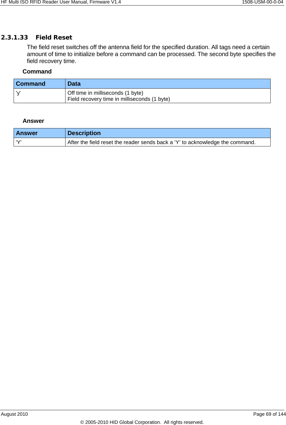
![1508-USM-00-0-04 HF Multi ISO RFID Reader User Manual, Firmware V1.4 2.3.1.31 Write EEPROM Writes to the internal reader EEPROM. It contains all start-up parameters and the device ID. Changes to the start-up settings will only go into effect after a reset of the device. Command Command Data 'wp' Address (1 byte), valid range 0Ah - EFh Data (1 byte) Answer Answer Description Data EEPROM data (1 byte) 'F' Error: Read after write failure 'R' Error: Out of range failure [entered address exceeds the address range] Example Command Description wp0A01 Set EEPROM address 0A (Station ID) to 01h 2.3.1.32 Reset This command executes a power on (software) reset. New configuration settings will be loaded. It resets all tags in the antenna field. Command Command Data 'x' None Answer Answer Description ‘MultiISO 1.2' + <CR> + <LF> ASCII Mode None Binary Mode 2.3.1.32.1 Disable Start-up Message If the start-up message is disabled in the protocol configuration 2 register, the ASCII mode does not respond with the version of the reader. 2.3.1.32.2 Reset Timing The power up timing depends on environmental conditions such as voltage ramp up. For handheld devices the timing can vary based on the charge state of the battery. Page 68 of 144 August 2010 © 2005-2010 HID Global Corporation. All rights reserved.](https://usermanual.wiki/HID-Global/5553/User-Guide-1322038-Page-68.png)
![1508-USM-00-0-04 HF Multi ISO RFID Reader User Manual, Firmware V1.4 2.3.2 ISO 14443 Type A (MIFARE ®) only commands 2.3.2.1 Increment value block (credit) Increments a value block with a defined value. A read is done automatically after a write to verify data integrity. The command fails if the source block is not in value block format. A previous login is needed to access a block. Command Command Data '+' Block # (1 byte); Value (4 bytes) Answer Answer Description Data Value (4 bytes) 'I' Error: value block failure 'F' Error: increment failure or inability to read after write 'N' Error: No tag in field [addressed tag not present or not responding] 'O' Error: Operation mode failure [tag is not ISO14443 type A compliant] Example Command Description +0400000001 Adds 1 to value block 4 +0500000100 Adds 256 to value block 5 2.3.2.1.1 No value block 'I' Specified block does not match the value format. The value block is corrupted. A backup block can be used to restore the correct value. Page 70 of 144 August 2010 © 2005-2010 HID Global Corporation. All rights reserved.](https://usermanual.wiki/HID-Global/5553/User-Guide-1322038-Page-70.png)
![HF Multi ISO RFID Reader User Manual, Firmware V1.4 1508-USM-00-0-04 2.3.2.2 Decrement value block (debit) Decrements a value block with a defined value. A read is done automatically after the write to verify data integrity. The command fails if the source block is not in value block format. A previous login is needed to access a block. Command Command Data '-' Block (1 byte) Value (4 bytes) Answer Answer Description Data Value (4 bytes) 'I' Error: value block failure 'F' Error: decrement failure or inability to read after write 'N' Error: No tag in field [addressed tag not present or not responding] 'O' Error: Operation mode failure [tag is not ISO14443 type A compliant] Example Command Description -0400000001 Subtract 1 to value block 4 -0500000100 Subtract 256 to value block 5 2.3.2.2.1 No value block 'I' Specified block does not match the value format. The value block is corrupted. A backup block can be used to restore the correct value. 2.3.2.3 Copy value block (backup) Copies a value block to another block of the same sector. A read is done automatically after the write to ensure data integrity. Used for backup and error recovery. A previous login is needed to access a block. Command Command Data '=' Source block (1 byte) Target block (1 byte) Answer Answer Description Data New value of target block (4 bytes). 'I' Error: value block failure 'F' Error: copy failure or inability to read after write 'N' Error: No tag in field [addressed tag not present or not responding] 'O' Error: Operation mode failure [tag is not ISO14443 type A compliant] August 2010 Page 71 of 144 © 2005-2010 HID Global Corporation. All rights reserved.](https://usermanual.wiki/HID-Global/5553/User-Guide-1322038-Page-71.png)
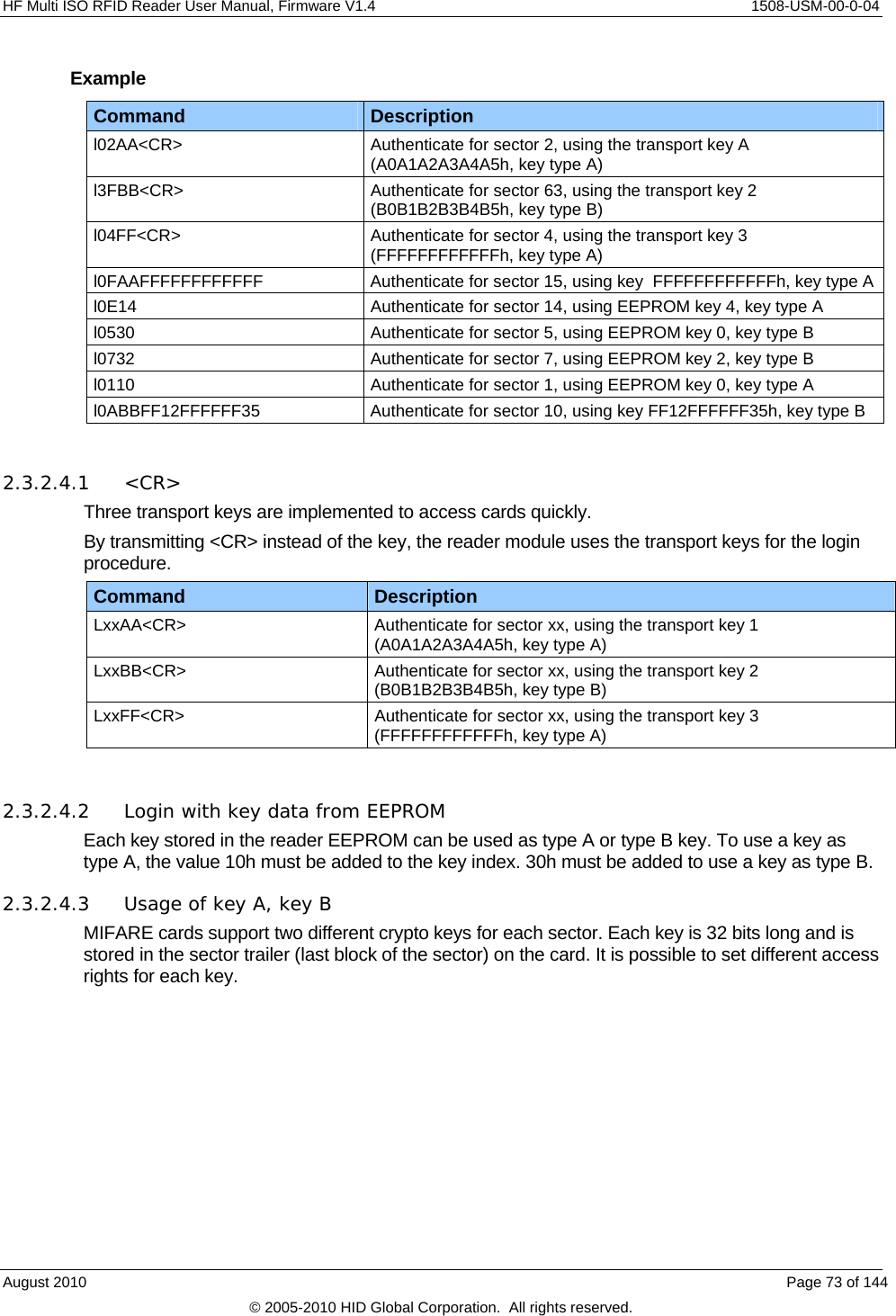
![1508-USM-00-0-04 HF Multi ISO RFID Reader User Manual, Firmware V1.4 Example Command Description =0405 Copy value block 4 to block 5 =0506 Copy value block 5 to block 6 2.3.2.3.1 Target block The target block does not need to be a valid value block. If the source block is not in value format, the command fails. 2.3.2.3.2 No value block 'I' Source value block is not in a valid value block. The value block is corrupted. A backup block can be used to restore the correct value. 2.3.2.4 Login (authenticate tag) Performs an authentication in order to access one sector of a MIFARE card. Only one sector can be accessed at a time. Command Command Data 'l' Sector (1 byte), valid range 00h - 3Fh Key type (1 byte) AAh authenticate with key type A FFh authenticate with key type A, transport key FFFFFFFFFFFFh BBh authenticate with key type B 10h … 2Fh authenticate with key type A using stored key (00h … 1Fh) 30h … 4Fh authenticate with key type B using stored key (00h … 1Fh) Key (6 bytes) / <CR> (1 byte), optional By transmitting <CR> instead of the key data authentication is done with manufacturer’s transport keys (A0A1A2A3A4A5h, B0B1B2B3B4B5h, FFFFFFFFFFFFh). Answer Answer Description data Login status (1 byte) 'L' Login success 'F' Error: General failure 'N' Error: No tag in field [addressed tag not present or not responding] 'O' Error: Operation mode failure [tag is not ISO14443 type A compliant] 'R' Error: Out of range [entered key type or the sector is out of range] 'X' Error: Authentication failed Page 72 of 144 August 2010 © 2005-2010 HID Global Corporation. All rights reserved.](https://usermanual.wiki/HID-Global/5553/User-Guide-1322038-Page-72.png)
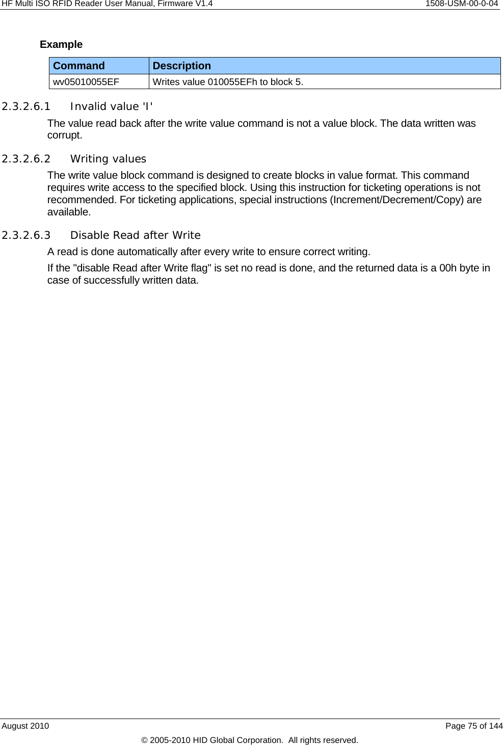
![1508-USM-00-0-04 HF Multi ISO RFID Reader User Manual, Firmware V1.4 2.3.2.5 Read value block Reads a value block. The command checks if data is in value block format. The read value block command needs a successful login. Command Command Data 'rv' Value block (1 byte) Answer Answer Description Data Read value (4 bytes) 'F' Error: General failure due to bad transmission conditions or address not authenticated 'I' Error: value block failure 'N' Error: No tag in field [addressed tag not present or not responding] 'O' Error: Operation mode failure [tag is not ISO14443 type A compliant] Example Command Description rv04 Reads value of block 4. 2.3.2.5.1 No value block 'I' The value read back after the write value command is not a value block. Data was corrupted. 2.3.2.6 Write value block This command formats a block as a value block containing a 32-bit value. Value blocks need a complete 16-byte block due to redundant storage. A successful login is required to run the command. Command Command Data 'wv' Value block (1 byte); Value (4 bytes) Answer Answer Description Data Written value (4 bytes) 'I' Error: value block failure 'F' Error: write failure due to bad transmission conditions or address not authenticated 'N' Error: No tag in field [addressed tag not present or not responding] 'O' Error: Operation mode failure [tag is not ISO14443 type A compliant] Page 74 of 144 August 2010 © 2005-2010 HID Global Corporation. All rights reserved.](https://usermanual.wiki/HID-Global/5553/User-Guide-1322038-Page-74.png)
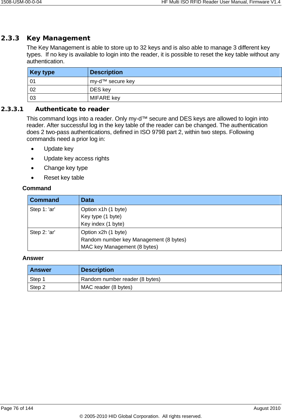
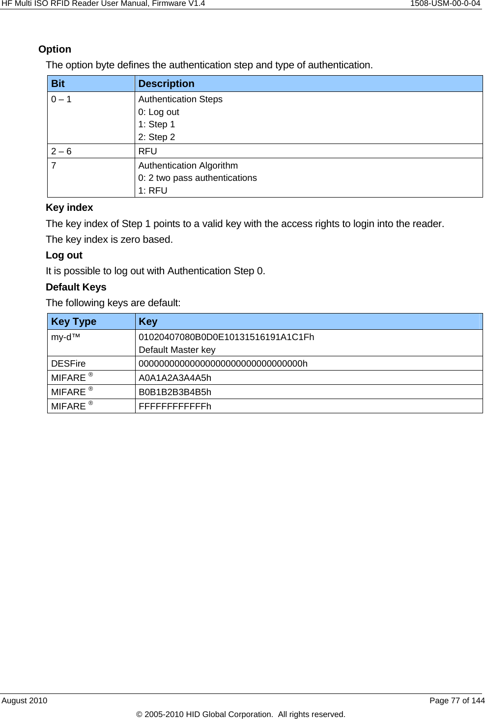
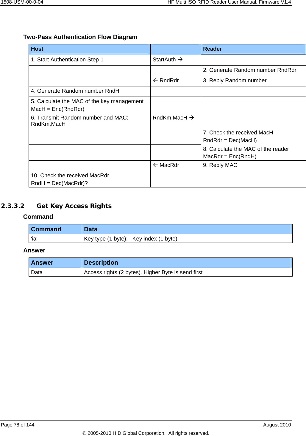
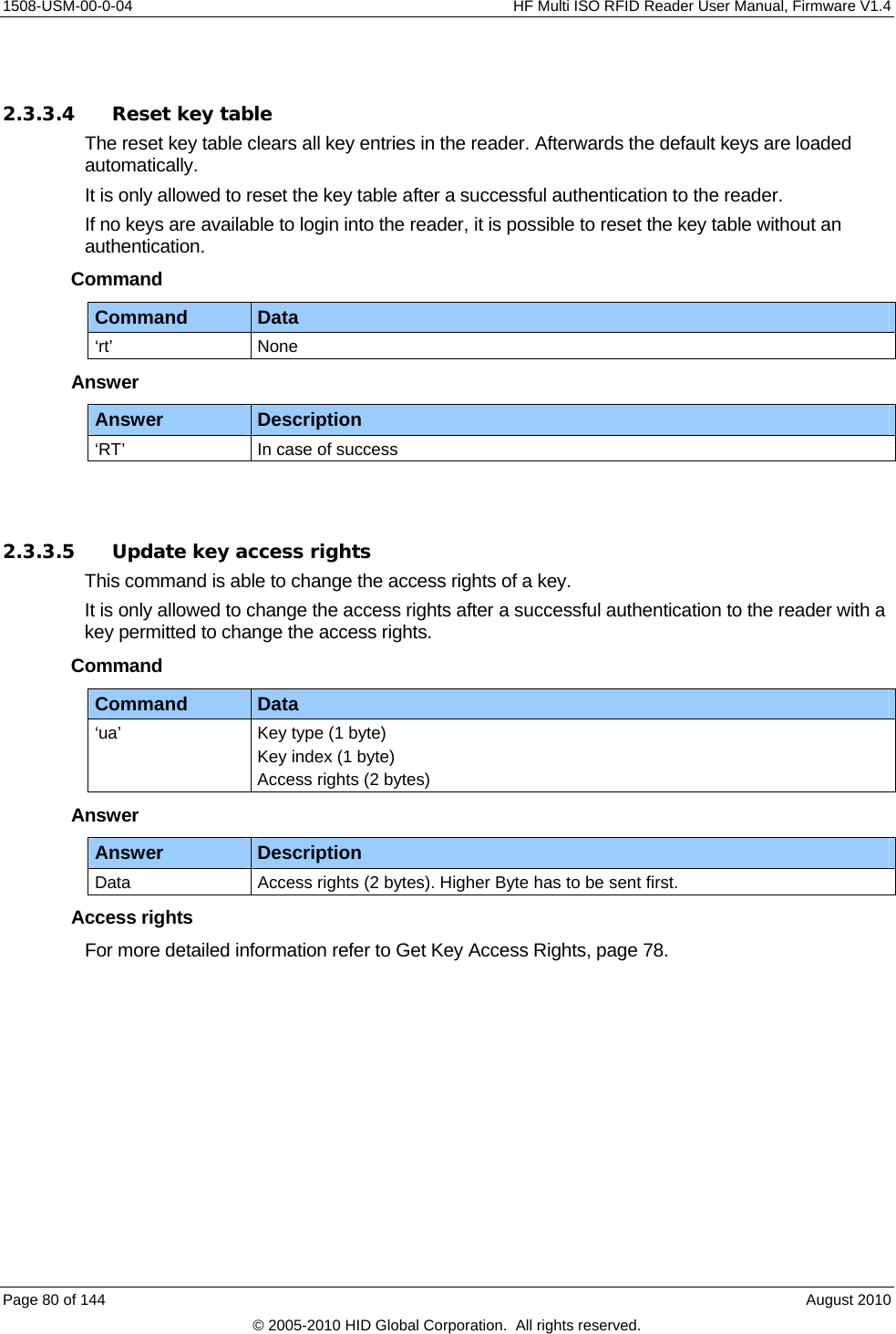
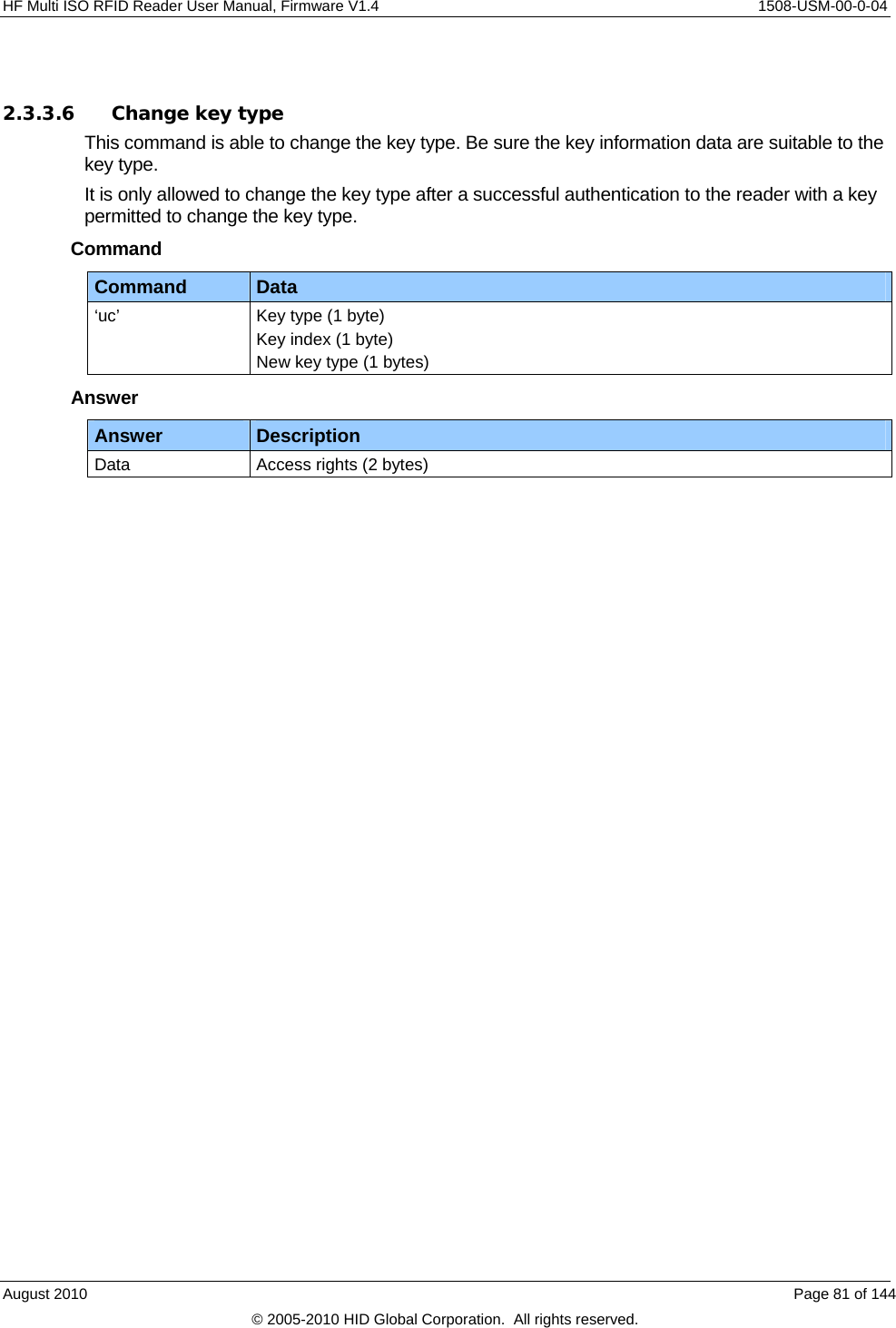
![HF Multi ISO RFID Reader User Manual, Firmware V1.4 1508-USM-00-0-04 Access Rights Only the default master key has all access rights. New keys got the default value 0000h. Bit Description 0 Allow Add Key 1 Allow Update Key 2 Allow Delete Key 3 Allow Reset Key table 4 – 7 RFU 8 RFU (Disable Serial Encryption) 9 Disable Authentication Tag 10 Allow Authentication Reader 11 Allow Changing Access rights 12 Allow Key Type changing 13 Allow 'ds' encryption 14 – 15 RFU 2.3.3.3 Get key status This command reports the key status of the reader. The reader lists for each key the key information. This command is used to inform the key management about the key status. The first byte of the response lists the number of stored keys. Command Command Data ‘it’ key type (1) Answer Answer Description my-d™ secure Data Number of keys (1 byte) [Key information (8 bytes)] Free User part (1 byte) Project ID (3 bytes) Logical Sector ID (1 byte) Key type (1 byte) KVV (2 bytes) DES Data Number of keys (1 byte) [Key information (10 bytes)] Option byte (1 byte) Free User part (9 bytes) MIFARE Data Number of keys (1 byte) [Key information 10 bytes)] Free User part (10 bytes) More than 255 bytes If the amount of data exceeds 255 bytes, than the answer is divided into more frames. If a frame follows, the Number of keys byte is extended with a set MSB (80h). August 2010 Page 79 of 144 © 2005-2010 HID Global Corporation. All rights reserved.](https://usermanual.wiki/HID-Global/5553/User-Guide-1322038-Page-79.png)
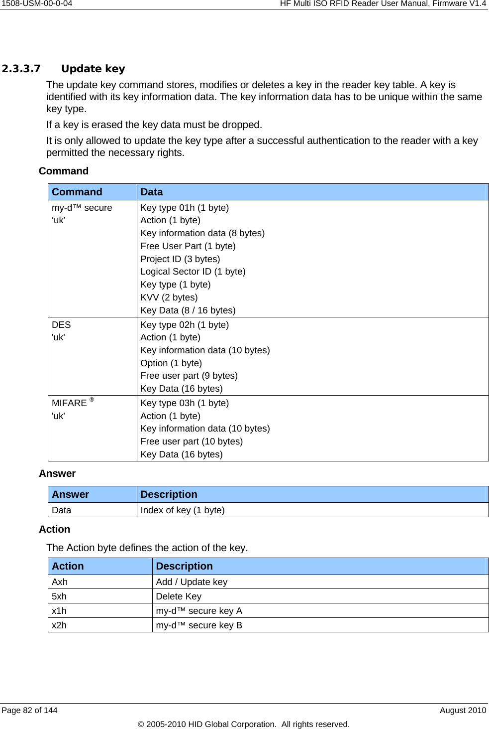
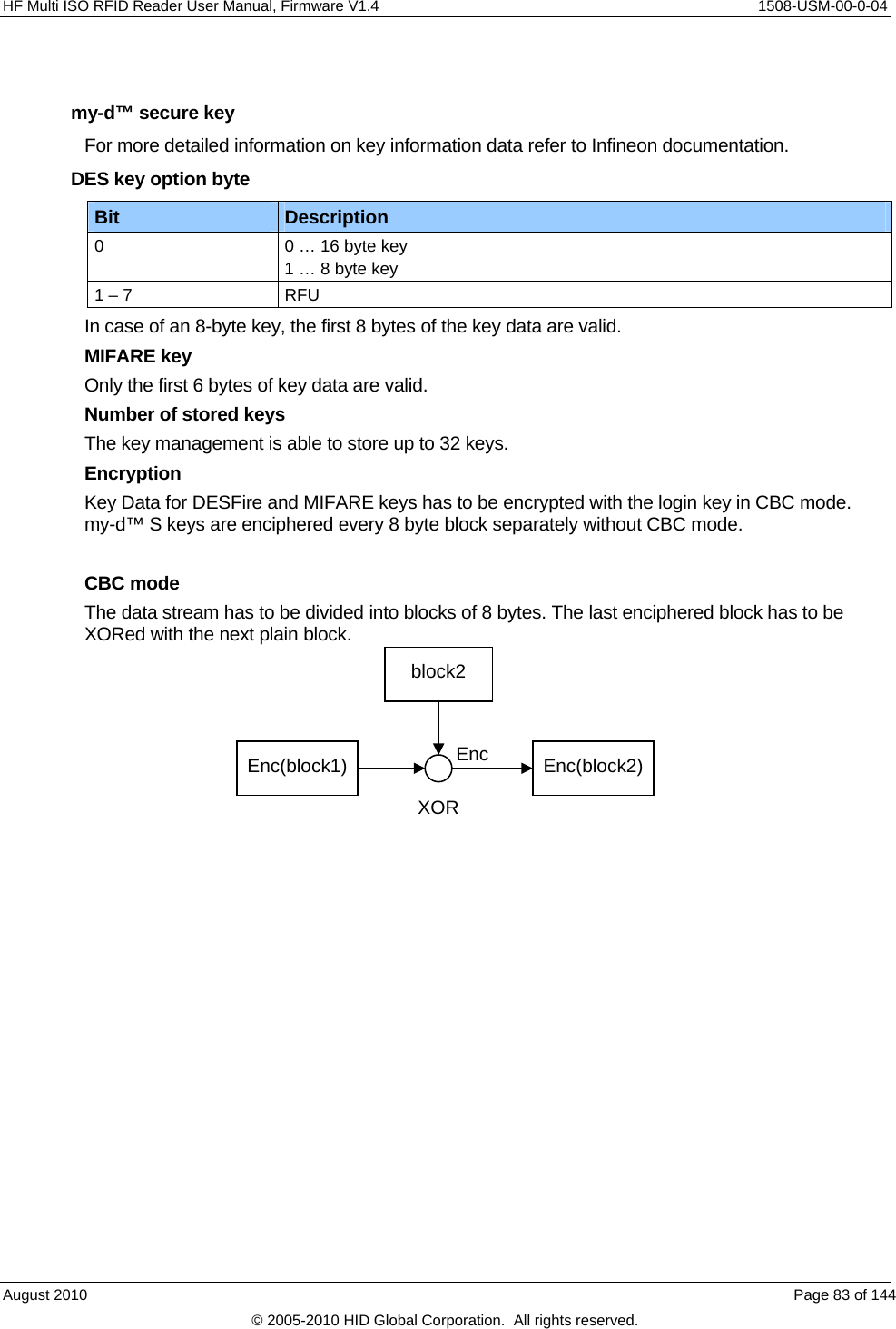
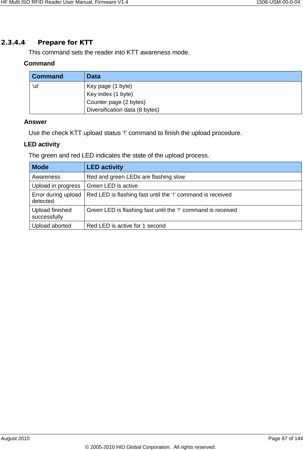
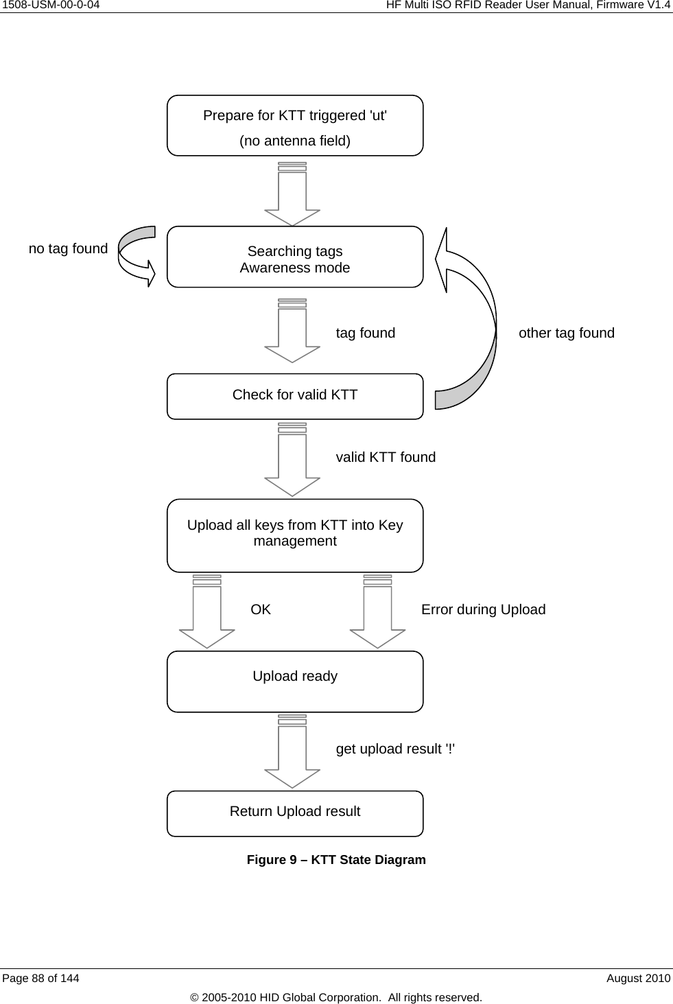
![1508-USM-00-0-04 HF Multi ISO RFID Reader User Manual, Firmware V1.4 2.3.4 my-d™ secure Note that ISO 14443 tags do not support the addressed mode. Bit 5 and 6 of the option byte are not used with ISO 14443 tags. The ISO 14443 tag only works in selected mode. 2.3.4.1 Abort KTT upload This command aborts the Prepare for KTT ‘ut’ command, if the reader is in prepare for KTT awareness mode. Command Command Data ‘*’ None Answer Answer Description 00h Prepare for KTT successfully aborted ‘F’ Prepare for KTT was not active No response Key uploading is in progress 2.3.4.2 Authenticate to sector The Authenticate to sector command sets up a secured transmission to a transponder. Command Command Data ‘as’ Option byte (1 byte) [UID (8 bytes)] Key page (1 byte) Key index (1 byte) Counter page (2 byte) Diversification data (8 bytes) Answer Answer Description ‘L’ In case of success Option byte The option byte defines the general behavior of the command. Note: ISO 14443 tags are only working in selected mode. Bit Description 7 RFU 6 If set the tag is in addressed mode. The UID is following as first 8 bytes after the option byte. The my-d™ frame is following. 5 If set the tag is selected. No UID is needed. 4 – 0 RFU Page 84 of 144 August 2010 © 2005-2010 HID Global Corporation. All rights reserved.](https://usermanual.wiki/HID-Global/5553/User-Guide-1322038-Page-84.png)
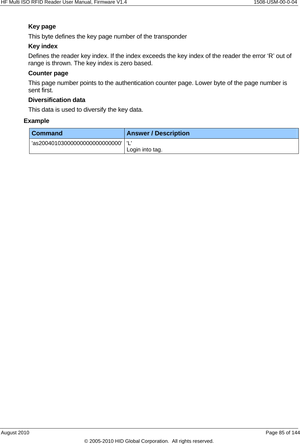
![1508-USM-00-0-04 HF Multi ISO RFID Reader User Manual, Firmware V1.4 2.3.4.3 Issue transponder key Writes a diversified key to the transponder. This command uses the write and Reread my-d™ command. Command Command Data ‘ik’ Option byte (1 byte) [UID (8 bytes)] Key index (1 byte) Destination page (2 bytes) Diversification data (8 bytes) [Sector index and access conditions (2 bytes)] Answer Answer Description ‘IK’ Key successfully written Option byte The option byte defines general behavior of the command. Note: ISO 14443 tags are only working in selected mode. Bit Description 7 If set the user mode is used and the MAC is calculated and added to the frame.If not set the issuer mode is used sector index and access conditions are included and no MAC is calculated. 6 If set the tag is in addressed mode. The UID is following as first 8 bytes after the option byte. The my-d™ frame is following. 5 If set the tag is selected. No UID is needed. 4 - 0 RFU Key index Defines the reader key index. If the index exceeds the key index of the reader the error ‘R’ out of range is thrown. The key index is zero based. Destination page Defines the transponder page index. Lower byte of the page number is sent first. Sector index and access conditions In issuer mode the sector index and the access conditions are added. Page 86 of 144 August 2010 © 2005-2010 HID Global Corporation. All rights reserved.](https://usermanual.wiki/HID-Global/5553/User-Guide-1322038-Page-86.png)
![HF Multi ISO RFID Reader User Manual, Firmware V1.4 1508-USM-00-0-04 2.3.4.5 my-d™ command This command sends and receives my-d™ plain and secure commands including my-d™ secure algorithm. Command Command Data ‘z’ Downlink length (1 byte) Option byte (1 byte) [UID (8 bytes)] my-d™ data (n bytes) Answer Answer Description Data Status byte: 00h (1 byte) Data without MAC and CRC (n bytes) Downlink length This byte is mandatory. It will define the length of the my-d™ data frame sent to the reader. The MAC, CRC and the framing overhead is not included. Option byte The option byte defines general behavior of the command. Note that ISO 14443 tags are only working in selected mode. Bit Description 7 If set the MAC is calculated and added to the frame 6 If set the tag is in addressed mode. The UID is following as first 8 bytes after the option byte. The my-d™ frame is following. 5 If set the tag is selected. No UID is needed. 4 – 0 RFU Data Data is sent as my-d™ plain command. It contains only data that is processed by the MAC calculation. If the tag is addressed, only valid with ISO 15693 tags, with its UID the first 8 bytes are interpreted as UID and not included into the MAC calculation. MAC calculation is done automatically if according flag is set. The ISO 15693 or the ISO 14443 frame is completed and the CRC is computed and added automatically. The commands Write Page, Restricted Write and Write Byte do not need any MAC verification for the answer. August 2010 Page 89 of 144 © 2005-2010 HID Global Corporation. All rights reserved.](https://usermanual.wiki/HID-Global/5553/User-Guide-1322038-Page-89.png)
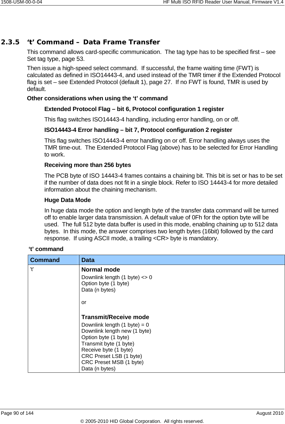
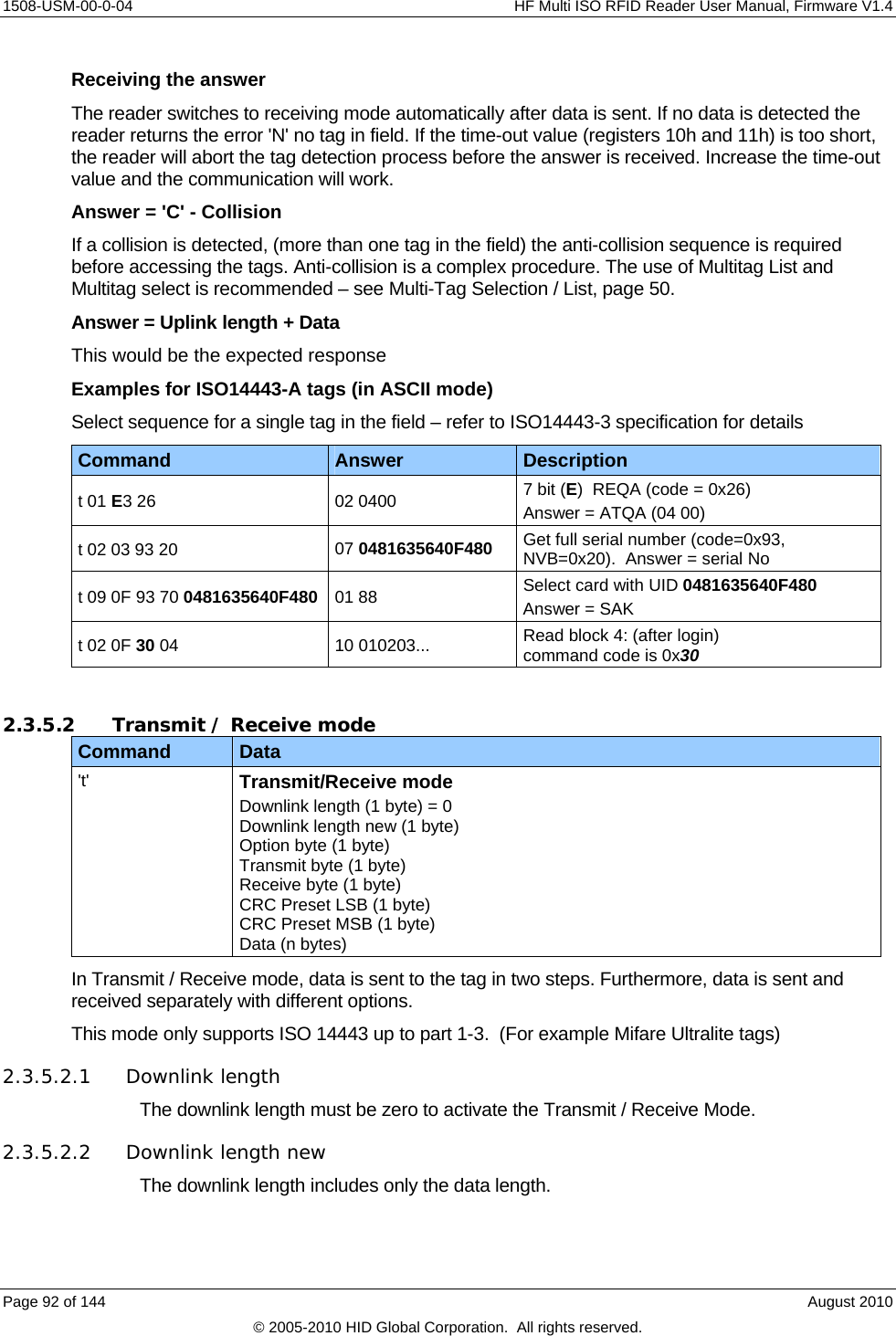
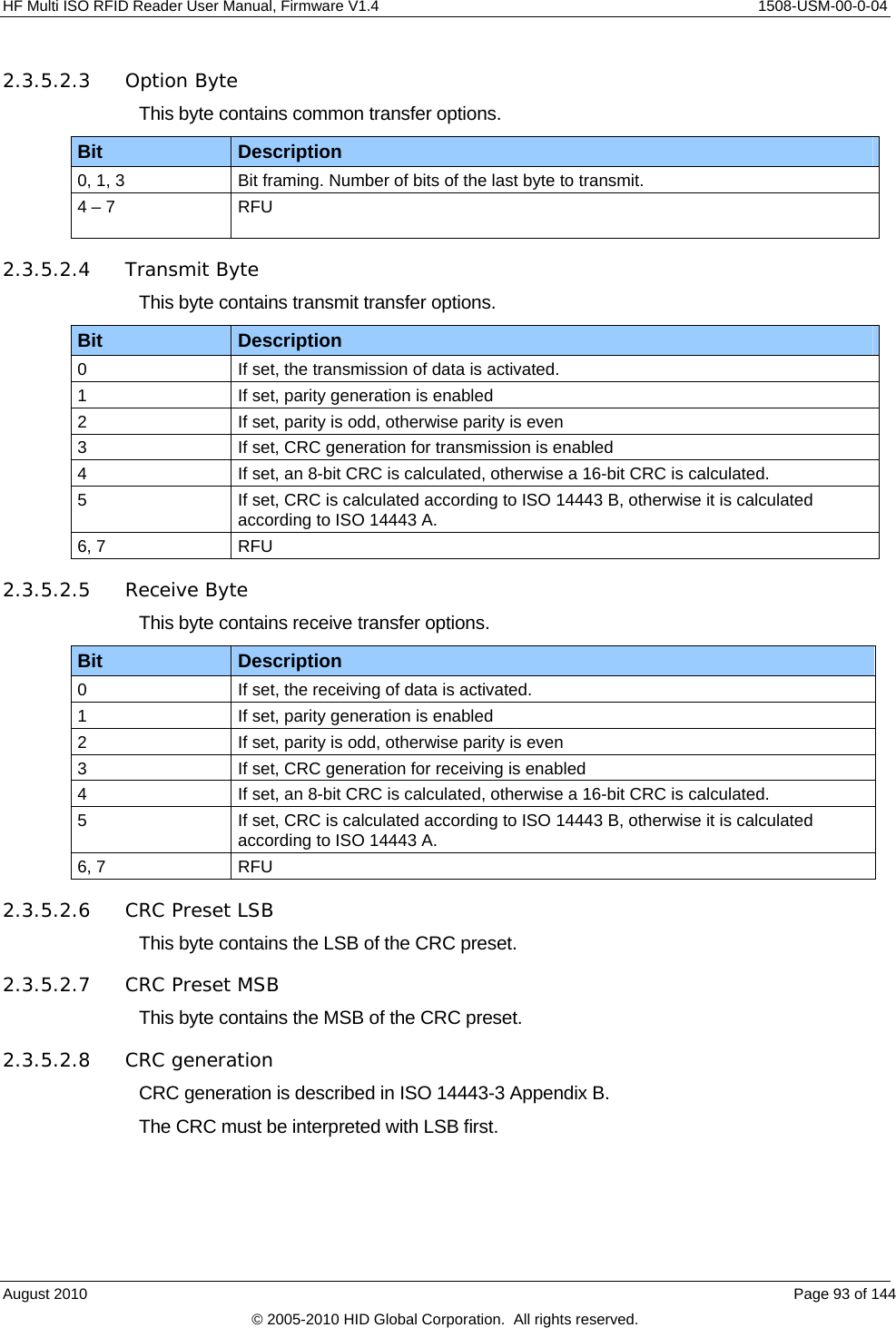
![HF Multi ISO RFID Reader User Manual, Firmware V1.4 1508-USM-00-0-04 Answer Answer Description Uplink length+Data Response of card 'C' Error: Collision 'F' Error: General failure 'N' Error: No tag in field [addressed tag not present or not responding] 'O' Error: Overflow 2.3.5.1 Normal Mode Downlink length The downlink length byte contains only the data length. This byte may not be zero. The CRC is computed automatically and is not included in the downlink length. CRC generation – see Option Byte - ISO 14443 or Option Byte – ISO 15693. CRC generation is described in ISO 14443-3 Appendix B. If enabled, interpret the CRC with the LSB first. If CRC checking and generation is disabled, the maximum size of data to receive and transmit decreases to 253 bytes. Option Byte - ISO 14443 This byte contains the transfer options for ISO 14443 and I-Code. For ISO 14443 type B, I-Code and SR176 tags, only bits 2 and 3 are interpreted. The crypto unit is only activated after a successful login. Bit Description 0 If set, parity generation is enabled 1 If set, parity is even, otherwise parity is odd 2 If set, CRC generation for transmission is enabled 3 If set, CRC checking for receiving is enabled If set, the crypto unit is deactivated prior to start of transmission. Only the login sequence switches on the crypto unit correctly. 4 5, 6, 7 Bit framing. Number of bits of the last byte to transmit. Option Byte - ISO 15693 This byte contains the transfer options for ISO 15693. Bit Description 7 If set the CRC is deactivated for transmit. 6 If set the CRC is deactivated for receive. 5 - 0 RFU August 2010 Page 91 of 144 © 2005-2010 HID Global Corporation. All rights reserved.](https://usermanual.wiki/HID-Global/5553/User-Guide-1322038-Page-91.png)
![1508-USM-00-0-04 HF Multi ISO RFID Reader User Manual, Firmware V1.4 Examples for ISO 14443 A, Innovision’s Jewel tag (in Binary mode) Sending the 'RID' command Command Answer Description oa OA Set tag type t00 01 07 01 07 00 00 26 02 00 0C Send ReqA (26) and receive the answer t00 01 07 01 00 00 00 78 00 Send first byte of RID command (78) t00 01 00 01 00 00 00 00 00 t00 01 00 01 00 00 00 00 00 t00 01 00 01 00 00 00 00 00 t00 01 00 01 00 00 00 00 00 t00 01 00 01 00 00 00 00 00 t00 01 00 01 00 00 00 00 00 t00 01 00 01 00 00 00 D0 00 t00 01 00 01 2F FF FF 43 06 00 00 00 00 00 00 Send last byte of RID command and receive the answer 2.3.6 ‘t’ command block format & examples For detailed coding of the Block format refer to ISO 14443-4:2001(E) section 7.1 The ‘t’ command block format is as specified in ISO 14443 part 4, and consists of some or all of the following elements: Prologue field Information field Epilogue field PCB [CID] [NAD] [INF] [EDC] 1 byte 1 byte 1 byte variable 2 bytes PCB – Protocol Control Byte [mandatory] The PCB is used to distinguish between three different block types (Information, Receive ready and Supervisory) as well as defining if CID is present and conveying block-related flags. CID – Card Identifier Byte [optional] 4-bit logical card address in the range of 00h to 0Eh, 0F is RFU. NAD – Node Address Byte [optional] Should be compliant to NAD as defined in ISO 7816-3. INF – Information Field [optional] Commands and data mainly used in the application. EDC – Error Detection Code [mandatory] EDC is defined as a 16-bit CRC. The reader calculates the CRC automatically (refer to section 2.3.5.2.3 Option Byte, Page 93). 2.3.6.1 Block formats - Example Description Data stream I-Block (no CID, no NAD) Application level command 02 INF EDC I-Block (CID=05, no NAD) Application level command 0A 05 INF EDC R-Block (no CID, no NAD) Acknowledged A2 EDC R-Block (CID=06, no NAD) Not acknowledged BA 06 EDC Page 94 of 144 August 2010 © 2005-2010 HID Global Corporation. All rights reserved.](https://usermanual.wiki/HID-Global/5553/User-Guide-1322038-Page-94.png)
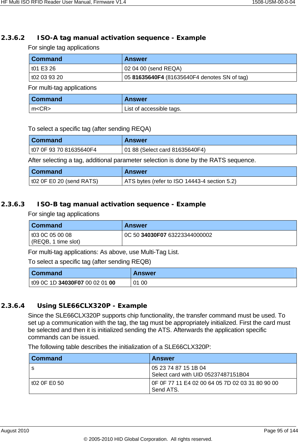
![1508-USM-00-0-04 HF Multi ISO RFID Reader User Manual, Firmware V1.4 2.3.6.5 Using ASK GTML - Example To work with the ASK GTML tag, the NoRxSOF flag has to be set to 1. The following table lists 2 examples: Command Answer t03 0C 00 0B 7F APGEN without ATR t04 0C 00 0B 3F 80 APGEN with ATR 2.3.6.6 Forcing higher baud rates - Example To force higher baud rates use the following sequence. Command Description oa Select tag type s Select tag t02 0F E0 80 RATS t03 0F D0 11 0A PPS h38 Force reader to use 256 Bytes frames h24 Force reader to use 424kBd 2.3.6.7 Using EAS with I-Code - Example To get the EAS answer from an I-Code tag enable the EAS bits on page 3 and send the following command with deactivated receiving CRC calculation: Command Description oi Preselect I-Code t06 04 E0 00 00 00 00 00 EAS command of I-Code with Family Code 00h and Application Identifier 00h. 2.3.6.8 Examples: How to send ISO 7816 commands? To work with ISO 7816 commands, the tag has to be set to ISO 14443-4 mode using the high speed select command. The data of the transfer data command is a combination of ISO 14443-4 block format and ISO 7816 command. First the ISO 14443-4 frame data has to be specified (refer to ISO 14443-4): PCB [CID] [NAD] … PCB is mandatory and the other data bytes are optional. After the block format data of the ISO 14443-4 the ISO 7816 command has to be specified (refer to ISO 7816-4): Definition of the ISO 7816 GetChallenge command: CLA INS P1 P2 Lc Data Le 00h 84h 00h 00h Empty Empty Maximum length of expected response The following table lists the example with an expected response length of 8: Command Answer t06 0F 02 00 84 00 00 08 GetChallenge command Page 96 of 144 August 2010 © 2005-2010 HID Global Corporation. All rights reserved.](https://usermanual.wiki/HID-Global/5553/User-Guide-1322038-Page-96.png)
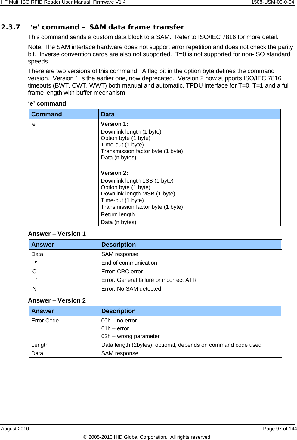
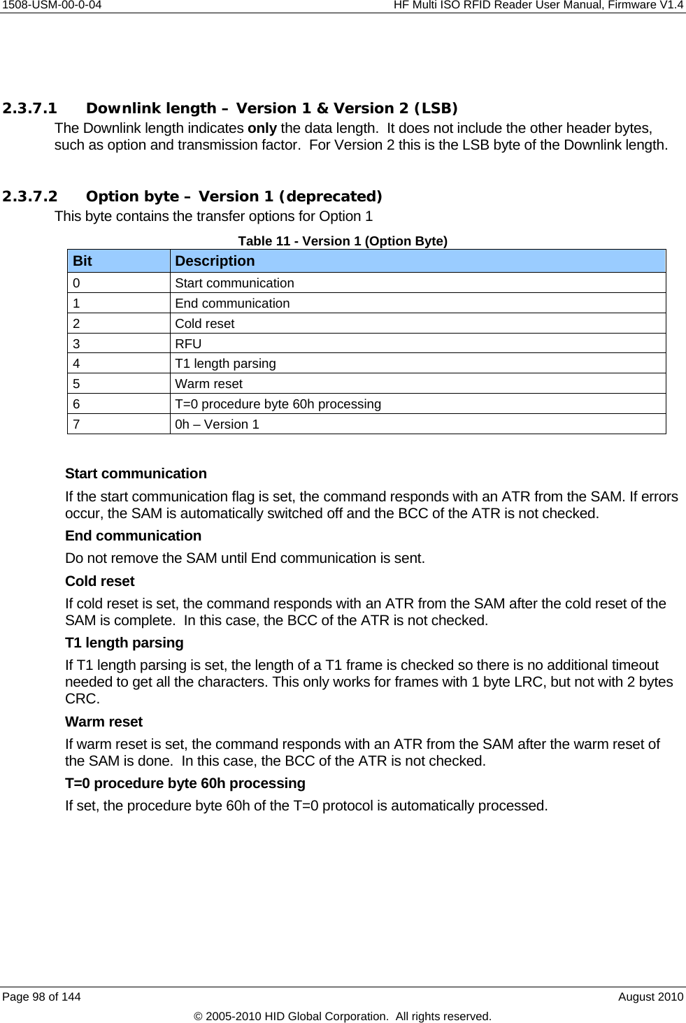
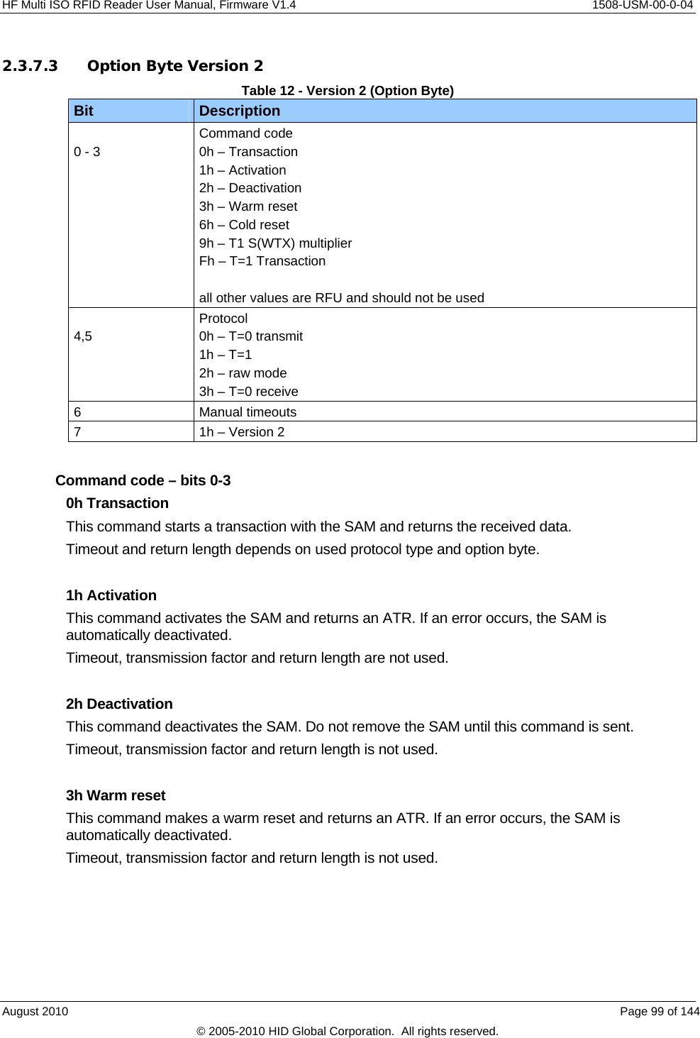
![1508-USM-00-0-04 HF Multi ISO RFID Reader User Manual, Firmware V1.4 Fh T=1 APDU implementation This command performs all of the wrapping for APDU message structures, using the T=1 block transmission protocol as detailed in ISO 7816-3. The ‘data’ field of the ‘e’ command comprises just the APDU Header [CLA, INS, P1, P2] and the Body [Lc, Data, Le] and the response APDU comprises the Body [Data] and Trailer [SW1, SW2] – see ISO 7816-4. Protocol – bits 4, 5 (The protocol flags are only used for the transaction command.) 0h T=0 This protocol type supports a full TPDU interface. Timeout is used as WWI value if the manual timeout flag is set, otherwise the timeout is automatically taken from the ATR. Return length is used. 1h T=1 For T=1 protocol include the frame in the data field. Timeouts are used as BWI/CWI values if the manual timeout flag is set, otherwise the timeouts automatically are taken from the ATR. Do not use return length. 2h RAW This protocol type uses a fixed timeout of WT = 9600etu and is only supported in the default speed (F/D=1). [NB If a zero return length is specified, the reader waits 9600etu after the last received character before returning the reply. Therefore, it is recommended to specify the return length (if known) in order to avoid any delay] Send the PPS command with this protocol type. Timeout is not used. Return length is used. 3h RFU Do not use the RFU value. Manual timeouts – bit 6 If set, the value of the timeout byte is used for T=0 and T=1 protocol; otherwise the timeouts are automatically taken from the ATR. 2.3.7.4 Time-out Version 1 The time-out byte is used as the communication time-out between two characters. One time slice is approximately 9.6ms. If setting the timeout value to zero, use a maximum timeout of 3.6 seconds. Use the TMR timeout until the first character is received. Version 2 The timeout byte represents the WWI value for T=0 protocol and BWI/CWI values for the T=1 protocol. BWI and CWI are encoded in the same way as in ATR. (See ISO/IEC 7816-3) These values are only used if the manual timeout flag is set – see Table 12 - Version 2 (Option Byte). Page 100 of 144 August 2010 © 2005-2010 HID Global Corporation. All rights reserved.](https://usermanual.wiki/HID-Global/5553/User-Guide-1322038-Page-100.png)
![HF Multi ISO RFID Reader User Manual, Firmware V1.4 1508-USM-00-0-04 2.3.7.5 Transmission Factor – Versions 1 & 2 This byte contains the clock rate conversion and baud rate adjustment according to ISO/IEC 7816-3. The default value on start-up is 11h (F/D = 1) The following pairs of F (clock rate conversion factor) and D (baud rate adjustment factor) are supported. F D Description 128 8, 16, 32 (Di = 4,5,6) Non ISO standard transmission factor [ T=0 not supported for these F|D values ] (Fi=8) 372 (Fi=0,1) 0, 1, 2, 4, 8, 12 (Di = 0,1,2,3,4,8) ISO standard transmission factors 512 32, 64 ISO standard transmission factors (Fi=9) (Di = 6,7) Clock A clock of 3.39MHz is used. Transmission Protocol The supported transmission protocol types are T=0 and T=1. For these protocol types, the ATR is checked. This command does not process the block frame of the transmission protocol T=1; all bytes are passed through. The user has to specify the block frame by itself. DESfire SAM The non-ISO standard transmission factors supporting baud rates up to 847500 Baud. Hardware The SAM interface does not support error repetition and does not check the parity bit. August 2010 Page 101 of 144 © 2005-2010 HID Global Corporation. All rights reserved.](https://usermanual.wiki/HID-Global/5553/User-Guide-1322038-Page-101.png)
![1508-USM-00-0-04 HF Multi ISO RFID Reader User Manual, Firmware V1.4 2.3.8 ‘e’ command block Examples – Version 1 & 2 Command Description e:00 01 10 11 (Version 1) Start communication Answer: ATR e:00 81 00 10 11 00 (Version 2) Start communication (T=0) e:00 91 00 10 11 00 (Version 2) Start communication (T=1) Answer: 00 len-ATR ATR e:04 00 10 11 FF 11 86 68 (V1) PPS Answer: FF 11 86 68 (if tag agrees with proposal) e:04 A0 00 00 11 04 FF 11 86 68 (V2) PPS Answer: 00 00 04 FF 11 86 68 (if tag agrees with proposal) e:00 20 10 11 (V1) Warm reset Answer: ATR e: 00 83 00 10 11 00 (V2) Warm reset (T=0) e: 00 93 00 10 11 00 Warm reset (T=1) Answer: 00 len-ATR ATR e:00 02 00 00 (V1) End communication Answer: P e:00 82 00 10 00 00 (V2) End communication (T=0) e:00 92 00 10 00 00 End communication (T=1) Answer: 00h The following commands are taken from the NXP DESFire8 SAM-X specification document e:05 00 00 10 11 00 00 84 00 00 08 GetChallenge for T=0 e:09 00 00 10 11 00 00 00 05 80 84 00 00 08 09 GetChallenge for T=1. This now includes the T=1 frame Answer: 00 len-reply reply (varies) e:08 00 10 11 00 5A 00 00 03 (3 bytes DF-AID) SelectApplication for T=0 e:0C 00 10 11 00 00 08 80 5A 00 00 03 SelectApplication for T=1 This now includes the T=1 frame (3 bytes DF-AID) EDC Answer: (2 bytes) – see DESFire SAM spec e:08 80 00 10 11 00 00 5A 00 00 03 (3 bytes DF-AID) SelectApplication for T=0 e:0C 90 00 10 11 00 00 00 08 80 5A 00 00 03 SelectApplication for T=1 This now includes the T=1 frame (3 bytes DF-AID) EDC Answer: 00 02 reply – see DESFire SAM spec e:08 9F 00 10 11 00 80 5A 00 00 03 (3 bytes DF_AID) DESFire SAM_SelectApplication using T=1 APDU. Notice there is no block format or EDC, just the ‘INF’ APDU data Answer: Data SW1 SW2 [ - 90 00 for ‘ack’] Page 102 of 144 August 2010 © 2005-2010 HID Global Corporation. All rights reserved.](https://usermanual.wiki/HID-Global/5553/User-Guide-1322038-Page-102.png)
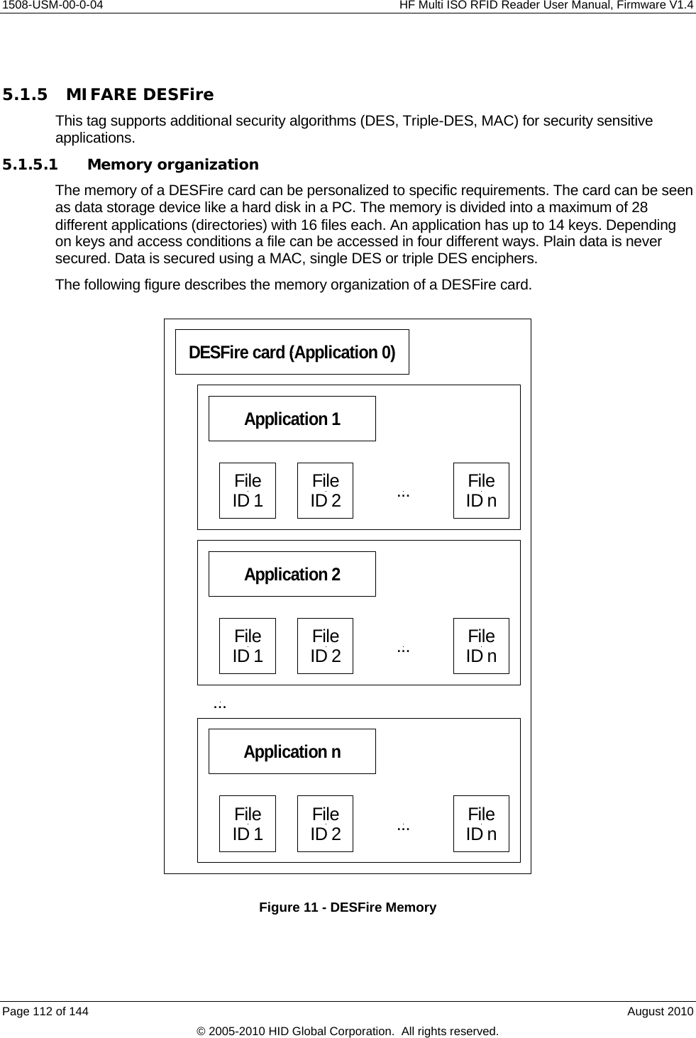
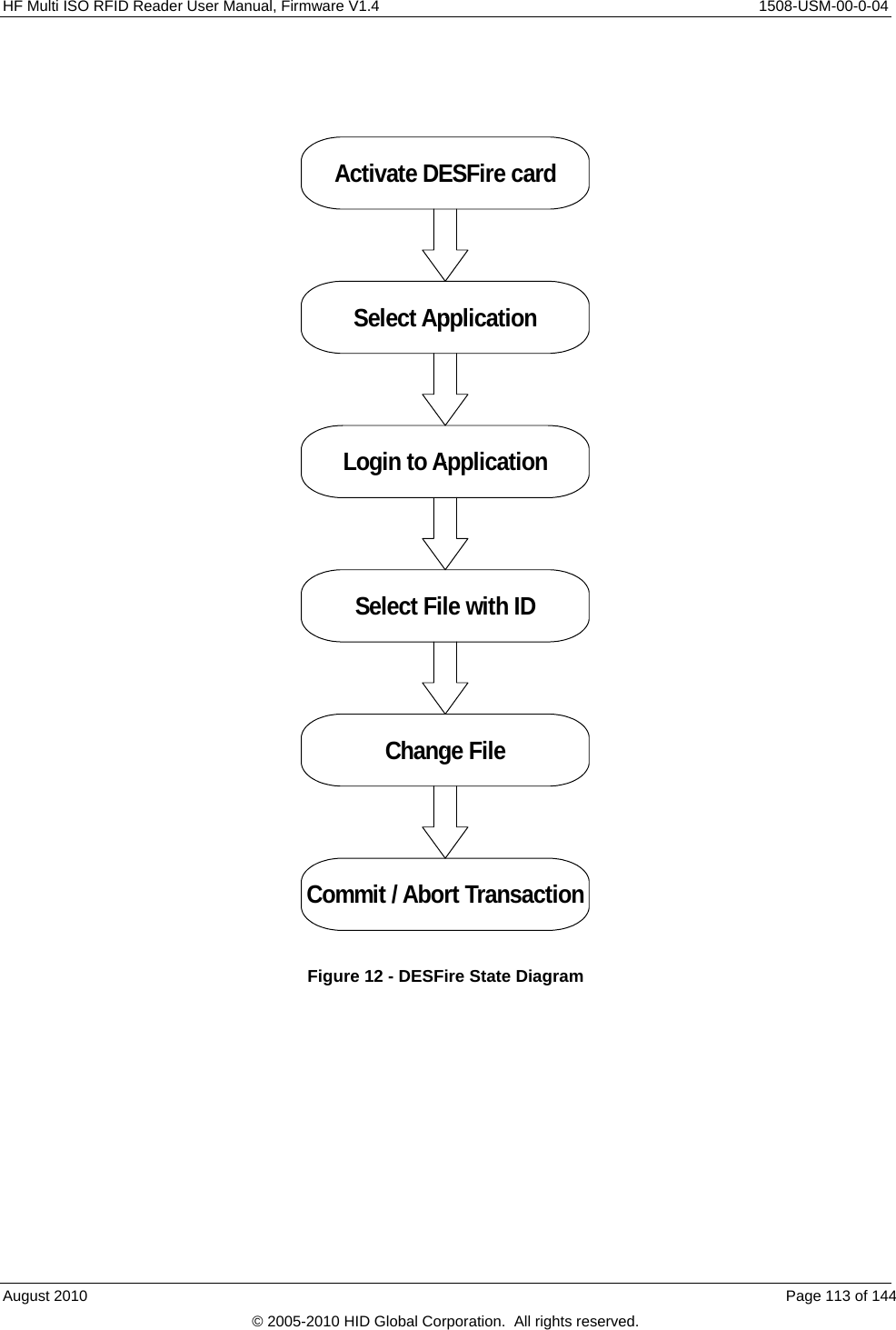
![1508-USM-00-0-04 HF Multi ISO RFID Reader User Manual, Firmware V1.4 5.1.5.2 Activate PICC Before accessing a DESFire card, the card must be selected. A DESFire card has a 7 byte UID. After activation, the card is powered up and ready to accept a DESFire command. Application 0 is selected automatically. 5.1.5.3 Select application To jump into another application, the application has to be selected. An application can be seen as a directory, which contains up to 16 files. The size of the application depends on the stored files. 5.1.5.4 Login to application Specific access rights can be set for each application. Login to an application allows changing the organization of the application. Login to a file opens a secured file for access. A file can be accessed in four different ways: without any security or secured with MAC, single DES or triple DES. 5.1.5.5 Select file Before accessing a file, the file must be selected 5.1.5.6 Change file A selected file can be changed according its access rights. If a file is secured, a login is required before changes can be made. 5.1.5.7 Commit / Abort transaction Value files, backup files, linear record files and cyclic record files only adapt their values after the commit transaction command is given. Several files can be changed within an application at the same time. The abort transactions command annuls all changes within an application. Power loss will cancel all modifications too. For more details about application settings and access rights refer to [2]. Page 114 of 144 August 2010 © 2005-2010 HID Global Corporation. All rights reserved.](https://usermanual.wiki/HID-Global/5553/User-Guide-1322038-Page-114.png)
![HF Multi ISO RFID Reader User Manual, Firmware V1.4 1508-USM-00-0-04 Appendix A - References [1] ISO/IEC 14443 Part 1-4, Identification Cards – Contact less integrated circuit(s) cards – Proximity cards [2] DESFire Documentation, NXP (formerly Philips), http://www.nxp.com [3] Data Encryption Standard (DES), FIPS PUB 46-3, Reaffirmed 1995 October 25 [4] HID Antenna Design Guide [5] NXP (formerly Philips); Application Note, MIFARE & I-Code, Micore Reader IC family Directly Matched Antenna Design [6] NXP (formerly Philips) Data sheet MC073933 for CL RC632 Reader IC [7] PayPass - ISO 14443 Implementation Specification PayPass - Terminal August 2010 Page 123 of 144 © 2005-2010 HID Global Corporation. All rights reserved.](https://usermanual.wiki/HID-Global/5553/User-Guide-1322038-Page-123.png)
![1508-USM-00-0-04 HF Multi ISO RFID Reader User Manual, Firmware V1.4 Appendix B - SAM Socket Details [These details appear in the Hardware Section (1), but are repeated here for convenience] Note: The power supply to the SAM must be turned off during the entire SAM insertion/withdrawal period; otherwise damage to the SAM may occur Communication with the SAM is performed using the ‘e’ command – see ‘e’ command – SAM data frame transfer, page 97. When using a SAM with the HID HF MultiISO OEM board, it is recommended that a 100nF decoupling capacitor be fitted between Vcc and GND close to the SAM socket to ensure proper operation. The complete circuit diagram is shown below. 7OEM Board89SAMModuleVccGNDCLKI/ORST100nF PIN-out for an 8 Pin SAM Socket and for a 6 Pin SAM Socket 8 NC7 I/O6 NC5 GND VCC 4RST 3CLK 2NC 18 PINSAM6 I/O5 NC4 GND VCC 3RST 2CLK 16 PINSAM Page 124 of 144 August 2010 © 2005-2010 HID Global Corporation. All rights reserved.](https://usermanual.wiki/HID-Global/5553/User-Guide-1322038-Page-124.png)
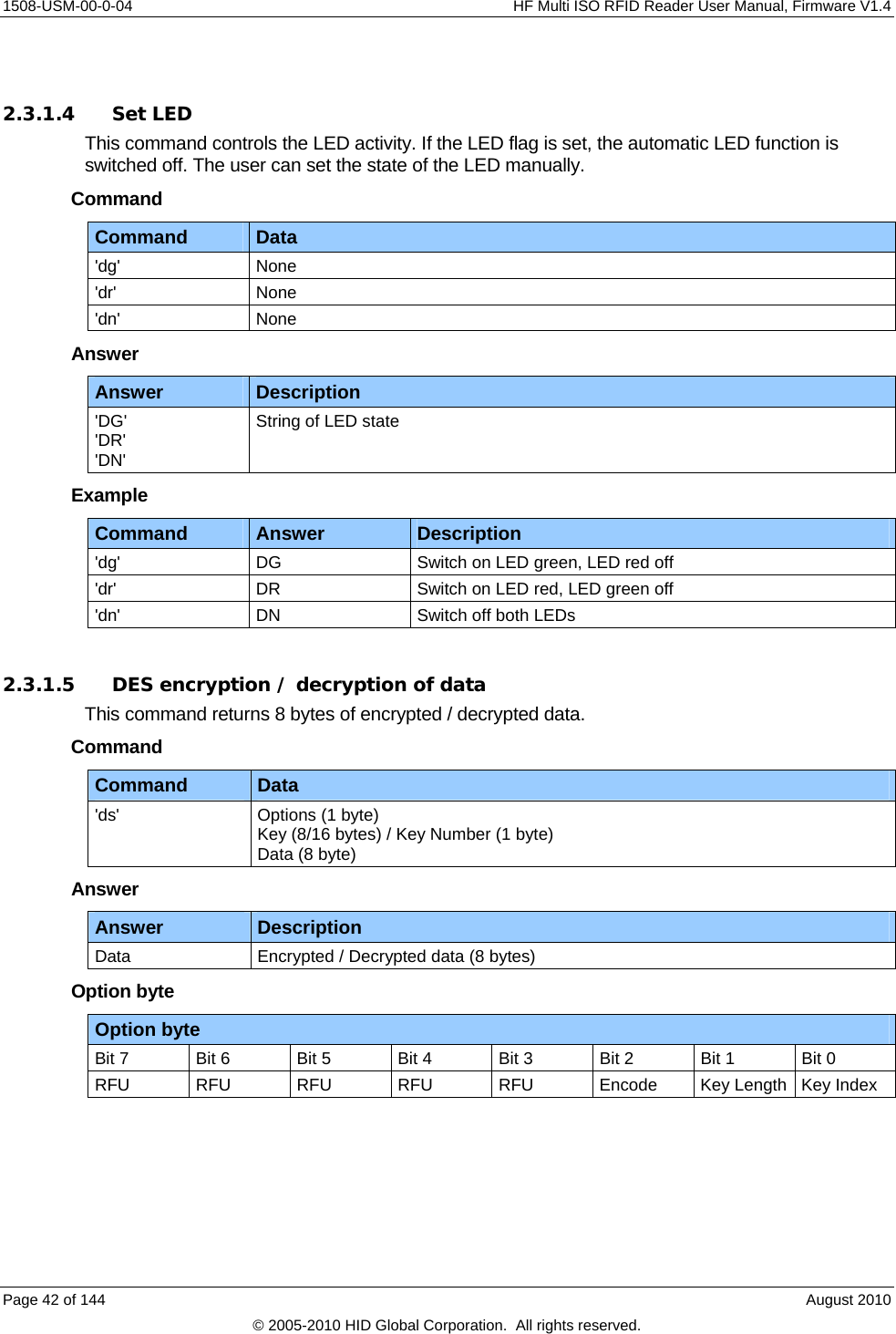
![HF Multi ISO RFID Reader User Manual, Firmware V1.4 1508-USM-00-0-04 Appendix C - Timings tCMD tEXEC tRES PC: Request Reader: Response Table 13 - Timings Command tEXEC [ms] Comments Common commands Cont. read (locked tag) 2.8 – 22.6 + Reset Off and Recovery Time Cont. read (worst case) 54 + 3x Reset Off and Recovery Time DES en/decryption 9.6 – 9.7 TDES en/decryption 28.7 – 28.8 High-speed select 'h08' (locked tag) 8.9 – 14.4 + Reset Off and Recovery Time + SFGT High-speed select 'h08' (no tag) 15 + 3x Reset Off and Recovery Time High-speed select 'h08' (worst case) 14.7 + 3x Reset Off and Recovery Time + SFGT Multi-select (locked tag) 5.8 – 11.4 + Reset Off and Recovery Time Multi-select (no tag) 67 + Reset Off and Recovery Time Multi-select (worst case) 67 + Reset Off and Recovery Time Antenna on 0.2 + Reset Recovery Time Antenna off 0.2 Port read 0.1 Port write 0.1 Read block 1.8 – 2.2 Write block 8.2 – 11 Reset 13.2 Select (locked tag) 5.4 – 22.8 + Reset Off and Recovery Time Select (no tag) 38 + 3x Reset Off and Recovery Time Select (worst case) 55 + 3x Reset Off and Recovery Time August 2010 Page 125 of 144 © 2005-2010 HID Global Corporation. All rights reserved.](https://usermanual.wiki/HID-Global/5553/User-Guide-1322038-Page-125.png)
![1508-USM-00-0-04 HF Multi ISO RFID Reader User Manual, Firmware V1.4 Command tEXEC [ms] Comments ISO 14443 Type A only commands Increment value block 18.4 Decrement value block 18.4 Copy value block 18.5 Read value block 2.3 Write value block 7.9 - 10.5 MIFARE Login 4.9 Power conditions Power on 79 Does not include rise time of power supply Enable on 85 Used was the default Command Guard Time (20h = 1.2ms). All timing data is advisory application information and does not form part of the specifications. It may change in future firmware releases. Note: All values specified in Table 13 - Timings depends on the tag used and Command Guard Time. Page 126 of 144 August 2010 © 2005-2010 HID Global Corporation. All rights reserved.](https://usermanual.wiki/HID-Global/5553/User-Guide-1322038-Page-126.png)