HID Global 5553 HID5553—Multi-ISO RFID Reader User Manual HID Install Guide
HID Global Corporation HID5553—Multi-ISO RFID Reader HID Install Guide
User Manual

15370 Barranca Parkway
Irvine, CA 92618-2215
OMNIKEY®
Multi-ISO (HID5553) RFID Reader
USER MANUAL
© 2005-2010 HID Global Corporation. All rights reserved.
1508-USM-00-0-04
Firmware Version 1.4
August 2010
Doc Number: 1508-USM-00, Rev D.1

1508-USM-00-0-04 HF Multi ISO RFID Reader User Manual, Firmware V1.4
Warning - Read before start-up!
The product may only be used for the intended purpose designed by the manufacturer. The
operation manual should be conveniently kept available at all times for each user.
Unauthorized changes that have not been sold or recommended by the manufacturer may have a
negative influence on the system the program has been installed or copied on. Such unauthorized
measures shall exclude any liability by the manufacturer.
The liability-prescriptions of the manufacturer in the issue valid at the time of purchase are valid for
the device. The manufacturer shall not be held legally responsible for inaccuracies, errors, or
omissions in the manual or automatically set parameters for a device or for an incorrect application
of a device.
Only qualified personnel should carry out installation, operation, and maintenance procedures.
Use of the program and its installation must be in accordance with national legal requirements.
When working on devices the valid safety regulations must be observed.
Read Me First
About this Guide
This manual describes the HF Multi ISO Reader. Its goal is to describe the reader, how it works,
how to integrate it and how to use it.
Contacts
Europe, Middle East and Africa
HID Global Corporation, Ltd. (Haverhill, UK)
email: eusupport@hidglobal.com
main: +44 (0) 1440 714 850
support: +44 (0) 1440 711 822
fax: +44 (0) 1440 714 840
HID GLOBAL, HID, the HID logo, and OMNIKEY are the trademarks or registered trademarks of HID
Global Corporation, or its licensors, in the U.S. and other countries.
Page 2 of 144 August 2010
© 2005-2010 HID Global Corporation. All rights reserved.

HF Multi ISO RFID Reader User Manual, Firmware V1.4 1508-USM-00-0-04
Contents
Scope ......................................................................................................................................................... 7
Overview ...................................................................................................................................................... 8
Definitions ........................................................................................................................................ 8
Abbreviations ................................................................................................................................... 8
Supported Tags.............................................................................................................................. 10
1 5553 Reader Core – Multi ISO.....................................................................................................12
1.1 Dimensions.............................................................................................................................. 12
1.2 Jumper 1 Details...................................................................................................................... 13
1.3 Jumper 2 Details...................................................................................................................... 14
1.4 External Connections .............................................................................................................. 15
1.4.1 Power Supply ...........................................................................................................................15
1.4.2 Antenna....................................................................................................................................16
1.4.3 Serial Interface .........................................................................................................................17
1.4.4 Function Control LEDs .............................................................................................................17
1.4.5 SAM Connector/Socket ............................................................................................................18
2 Software........................................................................................................................................19
2.1 Transmission Protocol............................................................................................................. 19
2.1.1 ASCII Protocol..........................................................................................................................19
2.1.2 Binary Protocol.........................................................................................................................20
2.2 Register Set............................................................................................................................. 23
2.2.1 EEPROM Memory Organization...............................................................................................23
2.2.2 Unique Device ID (00h – 04h) ..................................................................................................24
2.2.3 Station ID (0Ah)........................................................................................................................24
2.2.4 Protocol Configuration 1 (0Bh) .................................................................................................25
2.2.5 BAUD, Baud Rate Control Register (0Ch)................................................................................28
2.2.6 Command Guard Time (0Dh)...................................................................................................29
2.2.7 OPMODE - Operating Mode Register (0Eh).............................................................................29
2.2.8 Single Shot Time-Out (0Fh)......................................................................................................29
2.2.9 TMR, RF Time-Out Control Register (10h, 11h).......................................................................30
2.2.10 Type B framing Register (12h) .................................................................................................31
2.2.11 Protocol Configuration 2 (13h)..................................................................................................31
2.2.12 Reset Off Time (14h)................................................................................................................32
2.2.13 Reset Recovery Time (15h)......................................................................................................32
2.2.14 Application Family Identifier (16h) ............................................................................................32
2.2.15 Selection Time-Out ISO 14443A (17h).....................................................................................33
2.2.16 Selection Time-Out ISO 14443B (18h).....................................................................................33
2.2.17 Selection Time-Out SR176 (19h) .............................................................................................33
2.2.18 Selection Time-Out ISO 15693 (1Ah).......................................................................................33
2.2.19 Protocol Configuration 3 (1Bh) .................................................................................................33
2.2.20 Modulation Conductance 0 (1Dh).............................................................................................34
2.2.21 Threshold (1Eh)........................................................................................................................34
2.2.22 Protocol Configuration 4 (20h)..................................................................................................34
2.2.23 CID (21h)..................................................................................................................................35
2.2.24 RxWait (22h) ............................................................................................................................35
August 2010 Page 3 of 144
© 2005-2010 HID Global Corporation. All rights reserved.

1508-USM-00-0-04 HF Multi ISO RFID Reader User Manual, Firmware V1.4
2.2.25 Modulation conductance 1 (23h) ..............................................................................................35
2.2.26 Modulation conductance 2 (24h) ..............................................................................................35
2.2.27 Modulation conductance 3 (25h) ..............................................................................................36
2.2.28 User data (80h - EFh)...............................................................................................................36
2.3 Command Set.......................................................................................................................... 37
2.3.1 Common Command Details .....................................................................................................39
2.3.2 ISO 14443 Type A (MIFARE ®) only commands ......................................................................70
2.3.3 Key Management .....................................................................................................................76
2.3.4 my-d™ secure..........................................................................................................................84
2.3.5 ‘t’ Command – Data Frame Transfer ........................................................................................90
2.3.6 ‘t’ command block format & examples......................................................................................94
2.3.7 ‘e’ command – SAM data frame transfer ..................................................................................97
2.3.8 ‘e’ command block..................................................................................................................102
3 EMVCO Commands ...................................................................................................................103
4 Frequently Asked Questions ....................................................................................................104
4.1 Getting Started ...................................................................................................................... 104
4.2 Personalizing Multi ISO Reader ............................................................................................ 105
4.3 MIFARE Card Type ............................................................................................................... 106
4.4 MIFARE ................................................................................................................................. 106
4.5 Using NFC ............................................................................................................................. 108
5 Supported Tags..........................................................................................................................109
5.1 MIFARE Transponder Family................................................................................................ 109
5.1.1 MIFARE Standard ..................................................................................................................109
5.1.2 MIFARE Ultra-light .................................................................................................................111
5.1.3 MIFARE 4k.............................................................................................................................111
5.1.4 MIFARE Prox .........................................................................................................................111
5.1.5 MIFARE DESFire ...................................................................................................................112
5.1.6 my-d™ IC (SLE 55Rxx)..........................................................................................................115
5.2 ISO 14443 Type B................................................................................................................. 116
5.2.1 SR176 ....................................................................................................................................116
5.2.2 SRIX4K...................................................................................................................................117
5.3 ISO 15693.............................................................................................................................. 117
5.3.1 Coding of UID.........................................................................................................................117
5.3.2 Memory organization..............................................................................................................118
5.3.3 my-d™ IC (SRF55VxxP) ........................................................................................................118
5.3.4 EM 4135.................................................................................................................................119
5.4 ICODE ................................................................................................................................... 120
5.4.1 Memory organization..............................................................................................................120
5.4.2 Serial number .........................................................................................................................120
5.4.3 Write access condition............................................................................................................120
5.4.4 Special function (EAS,) AFI....................................................................................................121
5.4.5 User data................................................................................................................................121
5.5 ICODE EPC........................................................................................................................... 121
5.5.1 Memory organization..............................................................................................................121
5.5.2 Serial number .........................................................................................................................121
5.5.3 Read Block.............................................................................................................................121
5.5.4 Write Block .............................................................................................................................121
Page 4 of 144 August 2010
© 2005-2010 HID Global Corporation. All rights reserved.

HF Multi ISO RFID Reader User Manual, Firmware V1.4 1508-USM-00-0-04
5.6 ICODE UID ............................................................................................................................ 121
5.6.1 Memory organization..............................................................................................................121
5.6.2 Read Block.............................................................................................................................122
5.6.3 Write Block .............................................................................................................................122
Appendix A - References........................................................................................................................123
Appendix B - SAM Socket Details .........................................................................................................124
Appendix C - Timings .............................................................................................................................125
Appendix D ..............................................................................................................................................127
5553 Reader Board RS232 Compact MultiISO (RDHC-020xN0-02) ......................................... 127
5553 Reader Board USB Comfort Multi ISO (RDHS-0204N0-02)............................................... 134
5553 Desktop Multi ISO (RDHS-0204D0-02) .............................................................................. 139
4553 Mobile Multi ISO (RDHP-0206P0-02) ................................................................................. 140
Appendix E - Version History ................................................................................................................141
Appendix F - Approvals / Certificates...................................................................................................142
CE Declaration............................................................................................................................. 142
FCC Declaration........................................................................................................................... 143
RoHS Compliance........................................................................................................................ 144
List of Figures
Figure 1 - Reader Core - Top View............................................................................................................. 12
Figure 2 - Power Supply Option 1............................................................................................................... 15
Figure 3 - Power Supply Option 2............................................................................................................... 16
Figure 4 - Typical Antenna Tuning.............................................................................................................. 16
Figure 5 - OEM Board Serial Interface........................................................................................................ 17
Figure 6- Connecting External LEDs - Option 1.......................................................................................... 17
Figure 7 - Connecting External LEDs - Option 2......................................................................................... 17
Figure 8 - SAM Connector .......................................................................................................................... 18
Figure 9 – KTT State Diagram.................................................................................................................... 88
Figure 10 - State Diagram......................................................................................................................... 110
Figure 11 - DESFire Memory.................................................................................................................... 112
Figure 12 - DESFire State Diagram.......................................................................................................... 113
Figure 13 - 5553 Reader RS232 Compact Multi ISO - Top View ............................................................. 128
Figure 14 - 5553 Reader RS232 Compact Multi ISO - Side View ............................................................ 129
Figure 15 - 5553 Reader RS232 Compact Multi ISO - Front View........................................................... 129
Figure 16 - Pin Out – Jumper 3................................................................................................................. 129
Figure 17 - RS232 Configuration - Jumper 3 Pin Out............................................................................... 130
Figure 18 - RS422 Configuration - Jumper 3 Pin Out............................................................................... 131
Figure 19 – RS485 Configuration - Jumper 3 Pin Out.............................................................................. 132
Figure 20 - Jumper 4 Pin Out - Top View ................................................................................................. 132
Figure 21 - Jumper 4 Pin Out.................................................................................................................... 133
Figure 22 - 5553 Reader USB Comfort Multi ISO - Top View .................................................................. 135
Figure 23 - 5553 Reader USB Comfort Multi ISO - Front View ................................................................ 136
August 2010 Page 5 of 144
© 2005-2010 HID Global Corporation. All rights reserved.

1508-USM-00-0-04 HF Multi ISO RFID Reader User Manual, Firmware V1.4
Figure 24 - 5553 Reader USB Comfort Multi ISO - Bottom View............................................................. 137
Figure 25 - 5553 Reader USB Comfort Multi ISO - Jumper 5 Pin Out - Top View................................... 138
List of Tables
Table 1 - Pin out – Jumper 1....................................................................................................................... 13
Table 2 - Electrical characteristics of J1 PINs............................................................................................. 13
Table 3 - Pin out – Jumper 2....................................................................................................................... 14
Table 4 - Electrical characteristics of J2 PINs............................................................................................. 14
Table 5 - Common Command Overview..................................................................................................... 37
Table 6 - Card Specific Commands............................................................................................................ 38
Table 7 - Error Codes.................................................................................................................................. 38
Table 8 - Register Type with Corresponding Register................................................................................ 56
Table 9 - Sending Serial Data Frame ......................................................................................................... 60
Table 10 - Receiving Serial Data Frame..................................................................................................... 61
Table 11 - Version 1 (Option Byte) ............................................................................................................. 98
Table 12 - Version 2 (Option Byte) ............................................................................................................. 99
Table 13 - Timings .................................................................................................................................... 125
Table 14 - Pin out – Jumper 3 Detail ........................................................................................................ 130
Table 15 - J3 pins in RS232 Configuration - Electrical Characteristics .................................................... 130
Table 16 - J3 pins in RS422 Configuration - Electrical Characteristics .................................................... 131
Table 17 - J3 pins in RS485 Configuration - Electrical Characteristics .................................................... 132
Table 18 - J4 pins - Electrical Characteristics........................................................................................... 133
Table 19 - Pin Out of Jumper 5................................................................................................................. 138
Table 20 – J5 Pin - Electrical Characteristics ........................................................................................... 138
Page 6 of 144 August 2010
© 2005-2010 HID Global Corporation. All rights reserved.

HF Multi ISO RFID Reader User Manual, Firmware V1.4 1508-USM-00-0-04
Scope
The HID HF Multi ISO Reader Module supports a broad range of tags compliant with ISO 14443
type A and B standards, including SR176 tags, tags which belong to the NXP MIFARE family, ISO
15693 tags, ISO 18000-3, EPC and UID tags. An open command structure allows the device to
communicate with tags that use an operating system. The read/write unit supports ISO 14443-4
layer with automatic chaining, 256 byte buffer and frame length, extended time framing and up to
848kBaud transmission rates over the air interface.
Several protocols are available to enable the reader module to be connected to a variety of
equipment. The ASCII protocol facilitates the use of a simple terminal; the Binary protocol provides
robust communication more suitable for a dedicated host system. If a host computer is used, then a
function library is available, providing function calls rather than low-level ‘byte-bashing’.
For the SAM interface security features and DESFire credential DES encryption, the function library
provides access to these features in the Reader Module. The function library is available for
Windows CE and XP host applications.
Major applications are:
Access control, identification using security credentials
Ticketing using standard MIFARE and DESFire credentials
August 2010 Page 7 of 144
© 2005-2010 HID Global Corporation. All rights reserved.

1508-USM-00-0-04 HF Multi ISO RFID Reader User Manual, Firmware V1.4
Overview
Definitions
Anti-collision loop
An algorithm used to identify and handle a dialogue between a reader and one or more tags in its
antenna field.
ASCII notation
ASCII characters are listed within apostrophes, i.e. ‘x’ means a single x.
Hex notation
A hexadecimal value is marked with the suffix ‘h’, i.e. A1h has the value A1 hexadecimal.
Abbreviations
Abbreviation Description
AID Application ID
ASCII American Standard Code for Information Interchange
ATR Answer to Reset
ATS Answer to Select
AFI Application Family Identifier
Block For the MIFARE Standard one block contains 16 bytes
CBC Cipher Block Chaining
CID Card Identifier (logical card address, ISO 14443-4)
CRC Cyclic Redundancy Check
DES Data Encryption Standard, for more details about DES refer to [3].
DSFID Data storage format identifier
EDC Error Detection Code
EGT Extra Guard Time
EOF End of Frame
ETU Elementary time unit
Hex / xxh Value in Hexadecimal notation
I-block Information block
KTT Key Transfer Transponder
LSB Least Significant Bit or Byte
MSB Most Significant Bit or Byte
NAD Node Address (ISO 14443-4)
OSI Open System Interconnection
OTP One time programmable
PCB Protocol Control Byte (ISO 14443-4)
PCON Protocol Configuration byte of the reader
PPS Protocol and Parameter Selection
RATS Request for Answer to Select
Page 8 of 144 August 2010
© 2005-2010 HID Global Corporation. All rights reserved.

HF Multi ISO RFID Reader User Manual, Firmware V1.4 1508-USM-00-0-04
August 2010 Page 9 of 144
© 2005-2010 HID Global Corporation. All rights reserved.
Abbreviation Description
R-block Receive ready block
REQA Request ISO Type A
REQB Request ISO Type B
RFU Reserved for Future Use
S-block Supervisory block
SAM Secure Application Module
Sector For the MIFARE Standard one sector contains 4 blocks
SID Station ID
SFGT Guard time after RATS
SN Serial Number of a tag (a 32 bit number)
SOF Start of frame
TDES Triple DES
Value block 32 bit data block format. Used in ticketing application
<CR> Carriage return (0Dh)
<LF> Line feed (0Ah)
1508-USM-00-0-04 HF Multi ISO RFID Reader User Manual, Firmware V1.4
Supported Tags
For tag details see Supported Tags, page 109.
Tag
Manufacturer
Serial number
Read/Write operation
Transfer command
Comments
ISO 14443 A
MIFARE Standard NXP
MIFARE 4k NXP
MIFARE Ultra-light NXP
MIFARE ProX NXP
MIFARE DESFire NXP -
MIFARE Mini NXP
SLE66CLX320P Infineon
- encryption not included
SLE 55R04 / 08 Infineon - encryption included
Smart MX NXP -
Jewel Innovision
Topaz Innovision
ISO 14443 B
SLE6666CL160S Infineon
-
SR176 STM
SLIX 4K STM
ASK GTML2 ISO ASK -
ASK GTML ASK - extended setup needed
Sharp B Sharp -
TOSMART P0032/64 Toshiba -
Dual Interface
Page 10 of 144 August 2010
© 2005-2010 HID Global Corporation. All rights reserved.
HF Multi ISO RFID Reader User Manual, Firmware V1.4 1508-USM-00-0-04
August 2010 Page 11 of 144
© 2005-2010 HID Global Corporation. All rights reserved.
Tag
Manufacturer
Serial number
Read/Write operation
Transfer command
Comments
ISO 14443 A
compliant1 various -
ISO 14443 B
compliant2 various -
ISO 15693
EM 4135 EM
ICode® SLI NXP
LRI12 STM
LRI64 STM
with 10% modulation index
LRI128 STM
LRI2k STM
better performance with 10%
modulation index
SRF55VxxP Infineon
SRF55VxxS Infineon
encryption included
Tag-it™ HF-I Std TI
Tag-it™ HF-I Pro TI - - only in addressed mode
TempSense KSW
- Temperature logging
ICode
ICode® NXP
ICode® EPC NXP
ICode® UID NXP
1 Performance varies
2 Performance varies
1508-USM-00-0-04 HF Multi ISO RFID Reader User Manual, Firmware V1.4
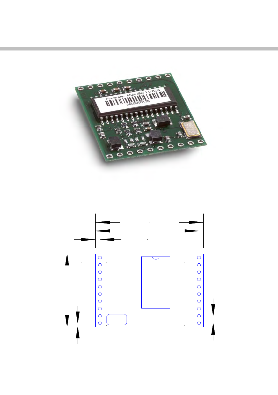
1 5553 Reader Core – Multi ISO
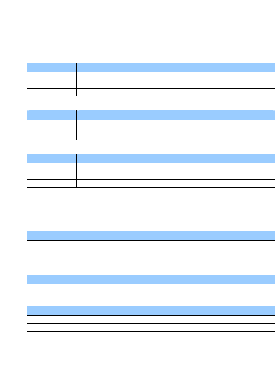
1.1 Dimensions
All dimensions listed in millimeters.
1
10 11
20J1 J2
2,54 mm
1,27 mm
29,21 mm
30,48 mm
1,27 mm
25,40 mm
Figure 1 - Reader Core - Top View
Page 12 of 144 August 2010
© 2005-2010 HID Global Corporation. All rights reserved.
HF Multi ISO RFID Reader User Manual, Firmware V1.4 1508-USM-00-0-04
1.2 Jumper 1 Details
Table 1 - Pin out – Jumper 1
PIN PIN No. Description
ARX 1 Antenna RX
ATX1 2 Antenna TX1
VDD 3 Supply Voltage
GND 4 Ground
ATX2 5 Antenna TX2
TGND 6 Antenna Ground
SAM CLK 7 SAM clock
SAM IO 8 SAM IO
SAM RESET 9 SAM Reset
RTS 10 Request to Send
Table 2 - Electrical characteristics of J1 PINs
PIN PIN No. Min Typ. Max. Description
ARX 1 1.1V 4.4V pk-pk Antenna RX
ATX1 2 13,56 MHz
34 VPP
13.56MHz
100 mAPP
50VPP
Antenna TX1
+4.5V +5.0V +5.5V Supply Voltage VDD 3
32mA 150mA 250mA Supply Current (without SAM)
GND 4 GND Ground
ATX2 5 13,56 MHz
34 VPP
13.56MHz
100 mAPP
50VPP
Antenna TX2
TGND 6 GND Antenna Ground
TTL
25mA
SAM CLK 7
3,39MHz
SAM clock
SAM IO 8 TTL 25 mA IO for SAM Input and SAM
Output
SAM RESET 9 TTL 25 mA SAM Reset
RTS 10 TTL 25 mA Request to Send
August 2010 Page 13 of 144
© 2005-2010 HID Global Corporation. All rights reserved.
1508-USM-00-0-04 HF Multi ISO RFID Reader User Manual, Firmware V1.4
Page 14 of 144 August 2010
© 2005-2010 HID Global Corporation. All rights reserved.
1.3 Jumper 2 Details
Table 3 - Pin out – Jumper 2
PIN PIN No. Description
VDD 20 Supply Voltage
GND 19 Ground
LEDg 18 LED green (reading LED)
LEDr 17 LED red
EN 16 Enable reader, open or logic high
MCLR 15 Master clear
USER 14 User Port
DIR 13 Direction of RS 485
TX 12 TX to PC
RX 11 RX from PC
Table 4 - Electrical characteristics of J2 PINs
PIN PIN No. Min Typ. Max. Description
RX 11 USART-TTL1 25 mA Rx to PC
To RS232, RS485 or RS422 device
driver
TX 12 USART-TTL1 25 mA Tx to PC
To RS232, RS485 or RS422 device
driver
DIR 13 TTL 25 mA Direction of RS 485
Logic High = Reader to Host
Logic Low = Host to Reader
USER 14 TTL3 25 mA User Port
MCLR 15 TTL4 Master clear
Leave unconnected
EN 16 ST5 25 mA Enable reader
logic low will disable the reader
Open or logic high
VDDmin
@ 25mA VDDtyp
@ 11mA VDDmax
@ 0 mA LED red
Output Voltage
LEDr 17
11mA 25mA External Resistor
min. 200
1 Universal Synchronous Asynchronous Receiver Transmitter
3 TTL buffer output / input. If user port is used as an output, a 1kΩ (current limiting) series resistor
has to be integrated into the connecting wire, otherwise the reader device can be damaged.
4 Voltage spikes below GND at the MCLR/VDD pin, including currents greater than 80mA, may
cause latch-up. Thus, a series resistor of 50-100 should be used when applying a "low" level to
the MCLR/VDD, rather than pulling this pin directly to GND.
5 Schmitt trigger buffer input
HF Multi ISO RFID Reader User Manual, Firmware V1.4 1508-USM-00-0-04
August 2010 Page 15 of 144
© 2005-2010 HID Global Corporation. All rights reserved.
PIN PIN No. Min Typ. Max. Description
1.4V
@ 11mA VDD
@ 0mA LED green (reading LED)
with 330 (internal serial) resistor
LEDg 18
11mA 15mA
GND 19 GND Ground
VDD 20 +4.5V +5.0V +5.5V Supply Voltage
IDD 32 mA 150 mA 250 mA Supply Current (Without SAM)
1.4 External Connections
1.4.1 Power Supply
If the supply voltage and any noise modulated on the supply voltage remains within the specified
limits, no further filtering is required. In some cases it is recommended to use additional filtering for
the power supply line. Insufficient power line filtering could cause unexpected or irregular
performance drops.
uC
20
19
OEM Board
+5V DC
Figure 2 - Power Supply Option 1
1508-USM-00-0-04 HF Multi ISO RFID Reader User Manual, Firmware V1.4
The board can be connected as shown in Figure 3 - Power Supply Option 2. Both alternatives are
possible and can be used as they fit best into the layout of the carrier board. The two VCC PINs and
the two GND PINs are connected internally.
3
4
OEM Board
+5V DC
Figure 3 - Power Supply Option 2
1.4.2 Antenna
The typical antenna tuning and matching network is shown in Figure 4 - Typical Antenna Tuning.
The external antenna has to have the right inductance and a certain resistor and capacitor
combination for an optimized frequency tuning and antenna matching.
6
5
1
2OEM Board
C1
C2
C3
C4
C5
L ANT
R1
Figure 4 - Typical Antenna Tuning
More details about the antenna design are available in the HID Antenna Design guide. Download
this document from http://www.hidglobal.com/Omnikey.
Reference the specific application notes for the NXP reader IC (MIFARE & I-Code, Micore Reader
IC family Directly Matched Antenna Design).
Page 16 of 144 August 2010
© 2005-2010 HID Global Corporation. All rights reserved.
HF Multi ISO RFID Reader User Manual, Firmware V1.4 1508-USM-00-0-04
1.4.3 Serial Interface
The OEM Board can be connected directly with a micro controller. Alternatively the OEM Board also
can be connected to most serial interface types by using the right interface converter circuit. In
order to optimize the communication quality the specific application note of the interface converter
circuit needs to be taken into consideration.
12
11
Interface
Converter
Circuit Host Interface
OEM Board
Figure 5 - OEM Board Serial Interface
1.4.4 Function Control LEDs
Two external LEDs can be connected to the OEM Board. There are two alternatives possible.
uC 18
17
OEM Board
330 Ohm
Figure 6- Connecting External LEDs - Option 1
uC 18
17
330 Ohm
OEM Board
330 Ohm
Figure 7 - Connecting External LEDs - Option 2
In both cases the LED supply voltage levels are TTL levels.
August 2010 Page 17 of 144
© 2005-2010 HID Global Corporation. All rights reserved.
1508-USM-00-0-04 HF Multi ISO RFID Reader User Manual, Firmware V1.4
1.4.5 SAM Connector/Socket
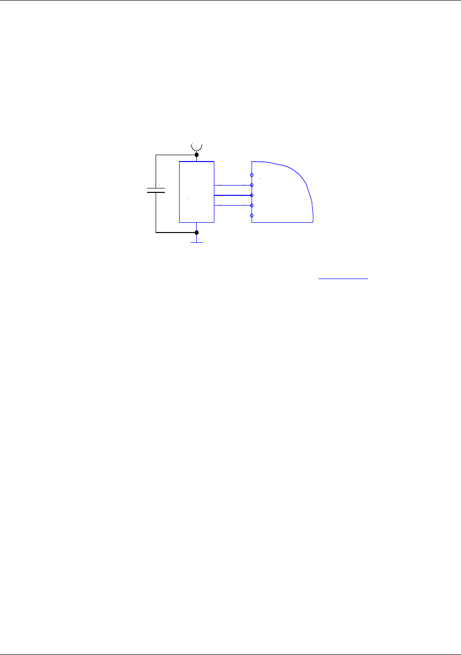
Note: The power supply to the SAM must be turned off during the entire SAM insertion/withdrawal
period; otherwise damage to the SAM may occur.
When using a SAM with the OEM board, it is recommended that a 100nF decoupling capacitor be
fitted between Vcc and GND close to the SAM socket to ensure proper operation. The complete
circuit diagram is shown in Figure 8 - SAM Connector.
7OEM Board
8
9
SAM
Module
Vcc
GND
CLK
I/O
RST
100nF
Figure 8 - SAM Connector
PIN-outs for 8 Pin SAM Socket and 6 Pin SAM Socket is shown in Appendix B.
Note: The SAM interface hardware does not support error repetition and does not check the parity
bit.
Page 18 of 144 August 2010
© 2005-2010 HID Global Corporation. All rights reserved.

HF Multi ISO RFID Reader User Manual, Firmware V1.4 1508-USM-00-0-04
2 Software
In order to offer the widest possible choice of interface, the MultiISO reader offers both ASCII and
Binary serial protocols – see Transmission Protocol, page 19.
EEPROM registers in the reader hold default settings for Station ID, protocol, serial and air-speed
settings, timing parameters and modulation index – listed in Register Set, page 23. These registers
are alterable using the Read/Write EEPROM commands detailed in Command Set page 37. The
register settings are applied to the reader through the configuration registers.
These configuration registers may be altered ‘on-the-fly’ to immediately affect performance by the
‘set configuration flag/register’ commands, but the changes are lost once the reader is powered
down, unless also written into the EEPROM registers. These and all other configurable settings are
detailed in the Register Set – Register Set, page 23.
General reader commands are listed in Command Set page 37 and detailed in Common Command
Details, page 39, dealing with the physical attributes of the reader – reset, LED control, User port
control, Antenna power – and the basic tag commands – include/exclude tag types, continuous
read, tag select and air speed select, and simple block read/write commands.
Tag-specific commands for MIFARE and My-D tags are listed in Sections ISO 14443 Type A
(MIFARE ®) only commands, page 70 and my-d™ secure, page 84, and commands to manipulate
keys are listed in Key Management, page 76.
For more complex commands, the ‘t’ command is used. This uses a data frame or packet to
exchange information – see ‘t’ Command – Data Frame Transfer, page 90 and ‘t’ command block
format & examples, page 94 for examples of use
To communicate with the optional SAM, the ‘e’ command is used. This also encapsulates a data
frame/packet to exchange information, based on the ISO7816 APDU – see ‘e’ command – SAM
data frame transfer, page 97 and ‘e’ command block, page 102 for examples of use.
2.1 Transmission Protocol
Two protocol modes are supported, with the default held in the reader EEPROM. As factory default,
the ASCII protocol is used, and the default serial configuration is 9600baud, n, 8, 1, with no
handshaking.
2.1.1 ASCII Protocol
This protocol is designed for easy handling. The commands may be issued using a terminal
program, such as HyperTerminal, and the data is transmitted as ASCII hexadecimal that can be
easily displayed on the terminal program.
Command Data
Variable length Variable length
August 2010 Page 19 of 144
© 2005-2010 HID Global Corporation. All rights reserved.
1508-USM-00-0-04 HF Multi ISO RFID Reader User Manual, Firmware V1.4
2.1.2 Binary Protocol
This protocol is designed for industrial applications with synchronization and frame checking. An
addressing byte for party line (master/slave, multi-drop) is also included.
The protocol usually requires a device driver. Data is transmitted in binary mode. The reader uses
an internal binary watchdog timer to ensure correct framing.
STX Station ID Length Data BCC ETX
1 byte 1 byte 1 byte Variable length 1 byte 1 byte
The binary frame version 2 is only sent to the host. It is implemented to give extended information to
the host. Version 2 must be enabled in the Protocol configuration 2 register.
STX Station ID Length Flags Data BCC ETX
1 byte 1 byte 1 byte 1 byte Variable length 1 byte 1 byte
2.1.2.1 STX
Start of transmission (02h)
2.1.2.2 Station ID
Unique ID of the station
00h: Reserved for the bus master. Readers send response to this device ID.
FFh: Broadcast message. All devices will execute the command and send their response.
2.1.2.3 Length
Length defines the length of the data block, including the flag byte, if binary protocol version 2 is
activated. If length is set to zero, 256 data bytes are transmitted. The reader module only can send
256 data bytes, but cannot receive commands with 256 bytes.
2.1.2.4 Flags
The flag byte gives additional information to the host.
Bit 3 – Bit 7 Bit 1 – Bit 2 Bit 0
RFU Leading Character Info Error State
Error State
If cleared, the command was processed successfully. If set, an error occurred.
Leading Character Info
Bit 1 & 2 defines how to interpret the data in the binary frame.
Bit 2 Bit 1 Description
0 0 No leading character available, all values are hexadecimal.
0 1 The data contains one leading character.
1 0 All data bytes are characters.
1 1 RFU
Page 20 of 144 August 2010
© 2005-2010 HID Global Corporation. All rights reserved.
HF Multi ISO RFID Reader User Manual, Firmware V1.4 1508-USM-00-0-04
2.1.2.5 Data
This part contains the command and the data. The command values are the same as in ASCII
protocol mode (‘x’, ‘s’, …) whereas data is transmitted in binary mode.
The length of the command block depends on the instruction.
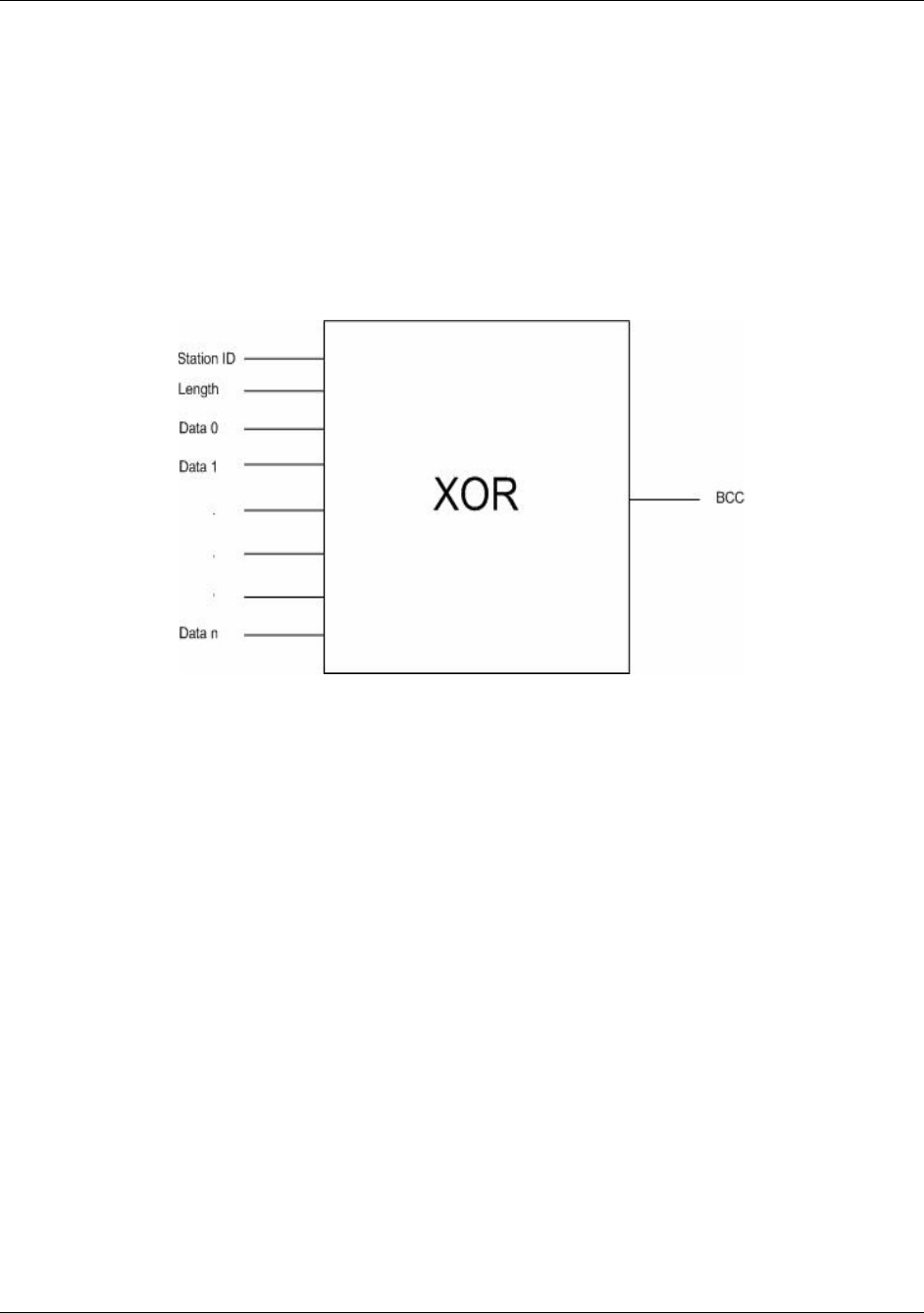
2.1.2.6 Block Check Character (BCC)
The BCC is used to detect transmission errors. The BCC is calculated XOR-ing each byte of the
transmission frame excluding the STX/BCC and ETX characters. The flags are part of the data.
)/(...)/()()( 0N
DataCommandXORXORDataCommandXORLengthXORStatIDBCC
2.1.2.7 ETX
End of transmission. (03h)
2.1.2.8 Remarks
If the reader device receives an invalid instruction frame (i.e. wrong BCC) or the requested station
ID does not match the internal ID of the reader, the command is not executed. The reader waits for
the next valid frame.
The automatic binary time-out (see
August 2010 Page 21 of 144
© 2005-2010 HID Global Corporation. All rights reserved.

1508-USM-00-0-04 HF Multi ISO RFID Reader User Manual, Firmware V1.4
Protocol Configuration 1 (0Bh), page 25) is used to detect incomplete binary frames.
2.1.2.9 Examples
02h 64h 01h 78h 1Dh 03h
STX Station ID Length ‘x’ BCC ETX
This instruction frame will reset the reader module with the station ID 64h.
Page 22 of 144 August 2010
© 2005-2010 HID Global Corporation. All rights reserved.

HF Multi ISO RFID Reader User Manual, Firmware V1.4 1508-USM-00-0-04
2.2 Register Set
The reader has several system registers used for customization purposes. These registers are
stored in its non-volatile EEPROM. The reader accepts changes to these settings only during the
start-up phase. [See Write EEPROM, page 68]
Some of the system registers are organized such that each of the 8 bits is an on-off selection for a
feature. These are referred to as Flags. [See Set Configuration Flags, page 54]
Clearing all RFU bits is recommended in order to guarantee compatibility with future releases.
In addition, direct changes to some of these system registers may be made at any time, with
immediate effect, but these changes are NOT stored in EEPROM and thus are lost when the reader
powers down. [See Set Configuration Flags, page 54 and Set Configuration Register page 56]
These ‘on-the-fly’ changes are mapped onto the EEPROM ‘registers’ or memory locations and do
not necessarily carry the same ‘register’ values.
The reader can store up to 32 authentication keys internally to login standard MIFARE cards. An
additional 32 keys can be stored for DESFire authentication. All keys are read only and cannot be
accessed through the interface lines.
2.2.1 EEPROM Memory Organization
Register Description
00h … 04h Unique device ID; read only
05h … 09h Administrative data; read only
0Ah Station ID
0Bh Protocol configuration 1
0Ch Baud rate
0Dh Command Guard Time
0Eh Operation Mode
0Fh Single shot time-out value
10h TMR low *
11h TMR high *
12h Type B framing *
13h Protocol configuration 2
14h Reset Off Time
15h Reset Recovery Time
16h Application Family Identifier
17h ISO 14443A Selection Time-out
18h ISO 14443B Selection Time-out
19h SR176 Selection Time-out
1Ah ISO 15693 Selection Time-out
1Bh Protocol configuration 3
1Ch Page Start
1Dh Modulation conductance 0 (Type B and SR176. Also ISO15693 if set to 10%
modulation)
1Eh Threshold
August 2010 Page 23 of 144
© 2005-2010 HID Global Corporation. All rights reserved.

1508-USM-00-0-04 HF Multi ISO RFID Reader User Manual, Firmware V1.4
Page 24 of 144 August 2010
© 2005-2010 HID Global Corporation. All rights reserved.
Register Description
1Fh Page number
20h Protocol configuration 4
21h CID
22h RxWait
23h Modulation conductance 1 (Type B and SR176)
24h Modulation conductance 2 (Type B and SR176)
25h Modulation conductance 3 (Type B and SR176)
26h - 7Fh RFU
80h … EFh User data
2.2.2 Unique Device ID (00h – 04h)
The unique device ID identifies a reader module. It is factory programmed and cannot be changed.
2.2.3 Station ID (0Ah)
Default = 01h
The station ID is used in binary mode to address a device in party line set up. The station ID can
range from 01h to FEh and can be set freely. The value 00h is reserved for the bus master. All
readers send their response to this device.
The broadcast message (FFh) forces all readers to response to the command.

HF Multi ISO RFID Reader User Manual, Firmware V1.4 1508-USM-00-0-04
2.2.4 Protocol Configuration 1 (0Bh)
Default = 41h
The protocol configuration register (PCON) specifies general behavior of the reader device, using
bit flags.
Protocol configuration register
Bit 7 Bit 6 Bit 5 Bit 4 Bit 3 Bit 2 Bit 1 Bit 0
Extended
ID Extended
Protocol Single-shot LED New serial
mode Multitag Protocol Auto- start
2.2.4.1 Auto start (default 1)
If set, the reader device will start up in continuous read mode automatically.
This is only valid in ASCII mode.
2.2.4.2 Protocol (default 0)
If Protocol is set to ‘1’, then the reader uses binary protocol mode. See
August 2010 Page 25 of 144
© 2005-2010 HID Global Corporation. All rights reserved.

1508-USM-00-0-04 HF Multi ISO RFID Reader User Manual, Firmware V1.4
Binary Protocol, page 20 for further information on the binary protocol format. Default setting =
ASCII protocol (0).
2.2.4.3 Multitag (default 0)
The Multitag flag will enable multi-tag recognition in continuous read mode. All tags are detected
and displayed. Due to the more complex search algorithm, the continuous read command
decreases its detection speed.
2.2.4.4 New Serial Mode (default 0)
If New Serial Mode is set to ‘1’, new serial mode is enabled. A leading character is added to the
serial number.
Leading Character Description
D ICode UID
E ICode EPC
I ICode
J ISO 14443 A Jewel tag
M ISO 14443 A
S SR 176
V ISO 15693
Z ISO 14443 B
2.2.4.5 LED (default 0)
If set the reader suppresses any LED activity. The user manages the state of the LEDs.
Page 26 of 144 August 2010
© 2005-2010 HID Global Corporation. All rights reserved.
HF Multi ISO RFID Reader User Manual, Firmware V1.4 1508-USM-00-0-04
2.2.4.6 Single Shot (default 0)
If Single Shot is set, the reader displays the serial number of a tag in continuous read mode once
within a specified time-out. The time-out is defined at EEPROM register 0Fh.
The delay time can be adjusted stepwise in 100ms steps. 00h indicates no delay and FFh
indicates infinite delay.
Note: The delay precision depends on reset off and reset recovery time.
2.2.4.7 Extended Protocol (default 1)
If Extended Protocol is set, the transfer data telegram command supports ISO14443-4 and
automatically process the WTX and chaining for smaller frames. This flag has to be set to enable
14443-4 error handling – see Extended Protocol (default 1), page 27.
If sending ISO 14443-3 commands this flag has to be switched off.
The transfer data telegram command is only supported in normal mode, not in transmit / receive
mode.
2.2.4.8 Extend ID (default 0)
If the Extend ID is set, the reader extends the serial number with additional information.
ISO 14443 A tags
Tag type / ReqA Serial number [SAK]
1 byte / 2 bytes 4 / 7 / 10 bytes 1 byte
Tag type / ReqA Serial number [SAK] ATS Used Speed [CID]
1 byte / 2 bytes 4 / 7 / 10 bytes 1 byte n bytes 1 byte 1 byte
The tag type byte indicates the type of cascade level.
Tag type Description
00h Cascade level 1 transponder
01h Cascade level 2 transponder
02h Cascade level 3 transponder
ISO 14443 B tags
Serial number Application data Protocol info MBLI/CID
4 bytes 4 bytes 3 bytes 1 byte
Serial number Application data Protocol info MBLI / CID Used Speed [CID]
4 bytes 4 bytes 3 bytes 1 byte 1 byte 1 byte
For detailed description of Application Data, Protocol Info and MBLI/CID, refer to the ISO 14443
documentation [1].
August 2010 Page 27 of 144
© 2005-2010 HID Global Corporation. All rights reserved.
1508-USM-00-0-04 HF Multi ISO RFID Reader User Manual, Firmware V1.4
2.2.5 BAUD, Baud Rate Control Register (0Ch)
Default = 00h
The baud rate register defines the communication speed of the reader device.
Baud rate register
Bit 7 Bit 6 Bit 5 Bit 4 Bit 3 Bit 2 Bit 1 Bit 0
RFU RFU RFU RFU RFU BS2 BS1 BS0
This register defines the baud rate of the device.
BS2 BS1 BS0 Baud rate
0 0 0 9600 baud (default)
0 0 1 19200 baud
0 1 0 38400 baud
0 1 1 57600 baud
1 0 0 115200 baud
1 0 1 230400 baud (depends on the used interface chip)
1 1 0 460800 baud (depends on the used interface chip)
With the high baud rates (230400 and 460800 baud), proper operation depends on the interface
chip used. Please note that some of the interface chips available do not support these high baud
rates.
The following table describes the exact baud rates used by the reader.
Baud rate Exact baud rate Difference
9600 baud 9603 baud 0.03 %
19200 baud 19207 baud 0.04 %
38400 baud 38305 baud -0.25 %
57600 baud 57458 baud -0.25 %
115200 baud 114915 baud -0.25 %
230400 baud 233793 baud 1.47 %
460800 baud 452000 baud -1.91 %
The following table describes the communication settings.
Description
8 data bits
No parity bit
1 stop bit
No flow control
2.2.5.1 CF Card Version
The Baud rate of the CF Card version is limited to 115200 baud. 230400 and 460800 are not
supported.
Page 28 of 144 August 2010
© 2005-2010 HID Global Corporation. All rights reserved.

HF Multi ISO RFID Reader User Manual, Firmware V1.4 1508-USM-00-0-04
2.2.6 Command Guard Time (0Dh)
Default = 20h (1,2ms)
The Command Guard Time is used to ensure that commands are not sent to fast consecutively.
Following commands are sent after the guard time is elapsed. One time slice is around 37,8us. The
longest timeout value is 9,6ms (FFh).
2.2.7 OPMODE - Operating Mode Register (0Eh)
Default = FFh (all)
The operation mode register defines which tag types the reader supports. This register enables fast
tag recognition because only defined tag types are requested.
Operation mode register
Bit 7 (MSB) Bit 6 Bit 5 Bit 4 Bit 3 Bit 2 Bit 1 Bit 0 (LSB)
RFU
ICODE UID
ICODE EPC
ISO 15693
ICODE
SR176
ISO 14443B
ISO 14443A
Innovision Jewel tag
Innovision Jewel tag is part of ISO 14443 Type A. It can not be separately switched on/off.
2.2.8 Single Shot Time-Out (0Fh)
Default = 0Ah (1 sec)
The time-out value defines the delay time between two responses of the reader. It only has effect in
continuous read mode. To enable the time-out, the single shot flag has to be set. See
August 2010 Page 29 of 144
© 2005-2010 HID Global Corporation. All rights reserved.

1508-USM-00-0-04 HF Multi ISO RFID Reader User Manual, Firmware V1.4
Protocol Configuration 1 (0Bh), page 25. One time-out slice is around 100ms. Exact timing depends
on the protocol used.
Value 00h indicates no delay time.
2.2.9 TMR, RF Time-Out Control Register (10h, 11h)
Default = 0300h (~230mS)
The RF time-out is used as reader card communication time-out. One time slice is around 300µs.
The longest time-out value is 19.7 seconds (FFFFh).
Value 0000h is not allowed and internally set to 0001h.
Page 30 of 144 August 2010
© 2005-2010 HID Global Corporation. All rights reserved.
HF Multi ISO RFID Reader User Manual, Firmware V1.4 1508-USM-00-0-04
2.2.10 Type B framing Register (12h)
Default value is 27h.
This register defines the communication settings of ISO 14443 B cards. The user can adjust this
register to set up the framing of type B cards individually. The register is applied when the operating
mode is set to type b (‘ob’) or toggle mode (‘ot’).
Type B Framing register
Bit 7 Bit 6 Bit 5 Bit 4 Bit 3 Bit 2 Bit 1 Bit 0
NoTx
SOF NoTx
EOF EOF
Width CharSpacing SOFWidth
Bit Description
NoTx SOF If set to 1 no SOF is sent
NoTx EOF If set to 1 no EOF is sent
EOF Width 0 Set the EOF to a length of 10 ETU
1 Set the EOF to a length of 11 ETU
CharSpacing Set the length of the EGT between 0 and 7 ETU
SOFWidth
00 Set the SOF to a length of 10 ETU low and 2 ETU high
01 Set the SOF to a length of 10 ETU low and 3 ETU high
10 Set the SOF to a length of 11 ETU low and 2 ETU high
11 Set the SOF to a length of 11 ETU low and 3 ETU high
2.2.11 Protocol Configuration 2 (13h)
Default value is 00h.
The protocol configuration register 2 (PCON2) further specifies the general behavior of the reader
device.
Protocol configuration 2 register
Bit 7 Bit 6 Bit 5 Bit 4 Bit 3 Bit 2 Bit 1 Bit 0
Disable
ISO 14443 -
4 Error
Handling
Enable ISO
14443B
Anti-
collision
Reset Recovery
Time Multiplier
Noisy
Environ-
ment
Disable start-
up message
Disable
multi-tag
reset
Enable
binary
frame v2
2.2.11.1 Disable multi-tag reset: bit 0 (default 0)
If set, the reader does not reset before the multi-tag list and multi-select command have been
performed.
2.2.11.2 Disable start-up message: bit 1 (default 0)
If Disable start-up message is set, the reader suppresses the start-up message in ASCII mode.
This flag is ignored in binary protocol mode.
August 2010 Page 31 of 144
© 2005-2010 HID Global Corporation. All rights reserved.

1508-USM-00-0-04 HF Multi ISO RFID Reader User Manual, Firmware V1.4
2.2.11.3 Enable binary frame v2: bit 2 (default 0)
If Enable binary frame v2 is set, the reader sends version 2 binary frames.
The get station ID command always sends version 1 binary frames!
2.2.11.4 Noisy Environment : bit 3 (default 0)
If Noisy Environment is set, the continuous read mode can only be aborted with the '.' character.
When working in a noisy environment, the probability for a reception of an arbitrary/stochastic
signal is quite high. This implies a high probability of an unintentional command execution. To
reduce this probability, only one character (out of 255) is chosen (‘.’) to be interpreted as the
continuous read stop command.
2.2.11.5 Reset Recovery Time Multiplier: bits 4-5 (default 0)
Multiplies the Reset Recovery Time, including the recovery time of the field reset command.
Reset Recovery Time Multiplier Reset Recovery Time
0 1x
1 2x
2 3x
3 4x
2.2.11.6 Enable ISO14443 B Anti-collision (default 0)
If set, the anti-collision algorithm for ISO 14443 B tags is enabled.
2.2.11.7 Disable ISO 14443-4 Error Handling (default 0)
If set, ISO14443-4 Error Handling is disabled. The error handling always uses the TMR time-out.
To enable Error Handling, the Extended Protocol flag in Protocol configuration 1 must be set. See
Extended Protocol (default 1), page27.
2.2.12 Reset Off Time (14h)
Default value is 0Ah.
The Reset Off Time register represents the field off time in ms.
This register is used for the select, continuous read and multi-tag commands.
2.2.13 Reset Recovery Time (15h)
Default value is 25h.
The Reset Recovery Time register represents the recovery time in ms after the field is turned on.
This register is used for the select, continuous read and multi-tag commands.
2.2.14 Application Family Identifier (16h)
Default value is 00h.
The AFI (Application Family Identifier) is only supported for ISO14443B and ISO15693 tags. If the
set value is different from 00h, the AFI is used. Only transponders with an identical AFI will answer
to the reader.
Page 32 of 144 August 2010
© 2005-2010 HID Global Corporation. All rights reserved.

HF Multi ISO RFID Reader User Manual, Firmware V1.4 1508-USM-00-0-04
2.2.15 Selection Time-Out ISO 14443A (17h)
The default value is 10h. (~4.8mS)
The Selection Time-out represents the reader card communication time-out for the select, high-
speed select, continuous read, multi-list, multi-select and MIFARE login command with ISO
14443A tags. Use low values for a better reaction time between the card and the reader. One time
slice is around 300us.
2.2.16 Selection Time-Out ISO 14443B (18h)
The default value is 10h. (~4.8mS)
The Selection Time-out represents the reader card communication time-out for the select, high-
speed select, continuous read, multi-list and multi-select commands with ISO 14443B tags. For a
better reaction time, use low values. One time slice is around 300µs.
2.2.17 Selection Time-Out SR176 (19h)
The default value is 10h. (~4.8mS)
The Selection Time-out represents the reader card communication time-out for the select,
continuous read, multi-list and multi-select command with SR176 tags. For a better reaction time,
use low values. One time slice is around 300µs.
2.2.18 Selection Time-Out ISO 15693 (1Ah)
The default value is 10h. (~9.6mS)
The Selection Time-out represents the reader card communication time-out for the select, high-
speed select, continuous read, multi-list, multi-select and MIFARE login command with ISO 15693
tags. Use low values for a better reaction time between the card and the reader. One time slice is
around 300us.
2.2.19 Protocol Configuration 3 (1Bh)
The Default value is 00h.
The protocol configuration register 3 (PCON3) further specifies the general behavior of the reader
device.
Protocol configuration 3 register
Bit 7 Bit 6 Bit 5 Bit 4 Bit 3 Bit 2 Bit 1 Bit 0
SAK Extended
ID ReqA
Extended ID ISO14443 Type B settings RFU Disable automatic
ISO 14443-4
timeouts
Page
Read
2.2.19.1 Disable automatic ISO 14443-4 timeouts: bit 0 (default 0)
If Disable automatic ISO 14443-4 timeouts is set the automatic ISO 14443-4 timeouts are
disabled. The timeouts specified with TMR registers are used.
2.2.19.2 Page read: bit 2 (default 0)
If set the continuous read mode retrieves the content of the tag instead of the serial number. The
register Page Start (1Ch) defines the start block and the Page Number (1Fh) defines the number
of blocks to be read.
August 2010 Page 33 of 144
© 2005-2010 HID Global Corporation. All rights reserved.

1508-USM-00-0-04 HF Multi ISO RFID Reader User Manual, Firmware V1.4
2.2.19.3 ISO14443 Type B Rx frame COM settings: bits 3-5 (default 00h)
The bits 3 - 5 of this register define the communication settings of ISO 14443 B cards for the
receiving frame.
Protocol Register 3: Bit 3 – 5
Bit 5 Bit 4 Bit 3
NoRxEOF NoRxEGT NoRxSOF
Bit Description
NoRxSOF If set to 1 a missing SOF of the received data frame will be ignored.
NoRxEGT If set to 1 a too short or too long EGT of the received frame will be ignored.
NoRxEOF If set to 1 a missing EOF of the received data frame will be ignored.
2.2.19.4 ReqA Extended ID: bit 6 (default 0)
If set the Extended ID information for ISO14443 A tags replaces the cascade level information (1
byte) with Request A answer (2 bytes).
2.2.19.5 SAK Extended ID: bit 7 (default 0)
If set the Extended ID information for ISO 14443 A tags will include the SAK byte behind the serial
number.
2.2.20 Modulation Conductance 0 (1Dh)
Default value is 05h.
The modulation defines the conductance of the output driver for the ISO 14443 B and SR176 tags
modulation time. If modulation is set to 10%, also include ISO15693 tags. Use this to regulate the
modulation index. Note that the conductance values are not linear! For further information, refer
to the NXP documentation. [6]
2.2.21 Threshold (1Eh)
Default value is EBh
The higher nibble of the Threshold register defines the minimum accepted signal strength at the
decoder input. The lower nibble of the Threshold register defines the collision level. For further
information, refer to the NXP documentation. [6]
2.2.22 Protocol Configuration 4 (20h)
Default value is 00h.
The protocol configuration register (PCON4) specifies general behavior of the reader device.
Protocol configuration 4 register
Bit 7 Bit 6 Bit 5 Bit 4 Bit 3 Bit 2 Bit 1 Bit 0
RFU RFU RFU RFU Huge data
mode
CID
Extended
ID
Disable
Read after
Write
WupA/B
Page 34 of 144 August 2010
© 2005-2010 HID Global Corporation. All rights reserved.

HF Multi ISO RFID Reader User Manual, Firmware V1.4 1508-USM-00-0-04
2.2.22.1 Disable Read after Write: bit 0 (default 0)
If set, the reader device will not make a read after write for the block write commands "w", "wb",
"wd" and "wv".
If the read after write is deactivated, acknowledge from the write commands is a 00h byte instead
of the written data.
2.2.22.2 WupA/B: bit 1 (default 0)
If set, the reader device will use WupA/B instead of ReqA/B during selection of an ISO 14443 tag.
Supported commands are select, high-speed select and multi-select.
2.2.22.3 CID Extended ID: bit 2 (default 0)
If set, the extended ID information for ISO 14443 A/B tags will be extended with the CID
information only for the high-speed select. The CID byte will be appended on the end of the
output.
2.2.22.4 Huge data mode: bit 3 (default 0)
If set, the huge data mode of the transfer data command will be enabled only for ISO 14443 A/B.
In huge data mode the option and length byte of the transfer data command will be turned off to
enable larger data transmission.
In ASCII mode a trailing CR byte is mandatory.
2.2.23 CID (21h)
Default value is 00h.
The Card Identifier (CID) is used to activate multiple ISO 14443-4 cards at the same time. If only
one tag at the same time is used this value should be left 0.
2.2.24 RxWait (22h)
Default value is 00h.
The RxWait value is a frame guard time until the receiver part will not receive any data. The value
is given in bit-clock cycles. A value of 0 indicates the RxWait timing will be done with predefined
values. For an air-speed of 106kBaud, the duration of one bit-clock cycle is ~9.4uS
2.2.25 Modulation conductance 1 (23h)
Default value is 00h.
This register is 1 of 4 different modulation conductance registers. The default used modulation
conductance register is 0. For more information refer to Modulation Conductance 0 (1Dh), page
34 and Set target modulation conductance register, page 57.
2.2.26 Modulation conductance 2 (24h)
Default value is 00h.
This register is 1 of 4 different modulation conductance registers. The default used modulation
conductance register is 0. For more information refer to Modulation Conductance 0 (1Dh), page
34 and Set target modulation conductance register, page 57.
August 2010 Page 35 of 144
© 2005-2010 HID Global Corporation. All rights reserved.

1508-USM-00-0-04 HF Multi ISO RFID Reader User Manual, Firmware V1.4
2.2.27 Modulation conductance 3 (25h)
Default value is 00h.
This register is 1 of 4 different modulation conductance registers. The default used modulation
conductance register is 0 For more information refer to Modulation Conductance 0 (1Dh), page 34
and Set target modulation conductance register, page 57.
2.2.28 User data (80h - EFh)
These registers are for free use.
Page 36 of 144 August 2010
© 2005-2010 HID Global Corporation. All rights reserved.

HF Multi ISO RFID Reader User Manual, Firmware V1.4 1508-USM-00-0-04
2.3 Command Set
The following table describes all the commands of the reader device. Each command returns an
answer to the host. Exceptions are mentioned explicitly. If fitted, the green LED acknowledges a
successfully executed command and the red LED indicates an error.
Table 5 - Common Command Overview
Description Detail Location Command
'!' Test continuous read / Check KTT upload status 2.3.1.1, page 39
'c' Continuous read 2.3.1.2, page 40
'.' Abort continuous read 2.3.1.2, page 40
‘dw’ De-select Wait 2.3.1.3, page 41
'dg' / 'dn' / 'dr' Set LED 2.3.1.4, page 42
'ds' DES encryption / decryption of data 2.3.1.5, page 42
'g' Get ID 2.3.1.6, page 43
'h' High-speed select 2.3.1.7, page 45
‘hc’ / ‘hw’ High-speed select Wait 2.3.1.8, page 48
'k' Lock block 2.3.1.9, page 49
'm' MultiTag select / tag list 2.3.1.10, page 50
‘o&’ Switch on/off CTS 2.3.1.11, page 51
‘o#’ 921kBaud Comms select 0, page 51
'o+a' / 'o+b' / 'o+d' / 'o+e' / 'o+i' / 'o+s' / 'o+v' Include tag type 2.3.1.13, page 52
'o-a' / 'o-b' / 'o-d' / 'o-e' / 'o-i' / 'o-s' / 'o-v' Exclude tag type 2.3.1.14, page 52
'oa' / 'ob' / 'od' / 'oe' / 'oi' / 'ot' / 'os' / 'ov' Set tag type 2.3.1.15, page 53
'of' Set configuration flags 2.3.1.16, page 54
'og' Set configuration register 2.3.1.17, page 56
‘om’ Set target modulation conductance register 2.3.1.18, page 57
'ox' Reread all registers 2.3.1.19, page 57
'poff' / 'pon' Antenna power off/on 2.3.1.20, page 59
'pr' / 'pw' Read / write user port 2.3.1.21, page 59
'q' Quiet 2.3.1.22, page 61
'ra' Resend last answer 2.3.1.23, page 62
'r' / 'rb' Read block 2.3.1.24, page 62
'rd' Read data (multiple blocks) 2.3.1.25, page 63
'rp' Read EEPROM register 2.3.1.26, page 63
's' Select 2.3.1.27, page 64
'v' Get version 2.3.1.28, page 65
'w' / 'wb' Write block 2.3.1.29, page 65
'wd' Write data (multiple blocks) 2.3.1.30, page 67
'wp' Write EEPROM register 2.3.1.31, page 68
'x' Reset 2.3.1.32, page 68
'y' Field reset 2.3.1.33, page 69
August 2010 Page 37 of 144
© 2005-2010 HID Global Corporation. All rights reserved.
1508-USM-00-0-04 HF Multi ISO RFID Reader User Manual, Firmware V1.4
Table 6 - Card Specific Commands
Command Description Detail Location
ISO 14443 Type A (MIFARE®) only commands
'+' Increment value block (credit) 2.3.2.1, page 70
'-' Decrement value block (debit) 2.3.2.2, page 71
'=' Copy value block (backup) 2.3.2.3, page 71
'l' Login (authenticate tag) 2.3.2.4, page 72
'rv' Read value block 2.3.2.5, page 74
'wv' Write value block 2.3.2.6, page 74
Key Management
'ar' Authenticate to reader 2.3.3.1, page 76
'ia' Get key access rights 2.3.3.2, page 78
'it' Get key status 2.3.3.3, page 79
'rt' Reset key table 2.3.3.4, page 80
'ua' Update key access rights 2.3.3.5, page 80
'uc' Change key type 2.3.3.6, page 81
'uk' Update key 2.3.3.7, page 82
my-d™ secure commands
'!' Check KTT upload status / Test continuous
read
'*' Abort KTT upload 2.3.4.1, page 84
'as' Authenticate to sector 2.3.4.2, page 84
'ik' Issue transponder key 2.3.4.3, page 86
'ut' Prepare for KTT 2.3.4.4, page 87
'z' my-d™ command 0, page 89
The following figure shows an overview of all error messages of the reader device.
Table 7 - Error Codes
Error Code Description
‘?’ Unknown command
'C' Collision or CRC/MAC Error
‘F’ General failure
‘I’ Invalid value format, specified block does not match the value format
‘N’ No tag in the field
'O' Operation mode failure or file not selected
‘R’ Command parameter out of range
'X' Authentication failed
Page 38 of 144 August 2010
© 2005-2010 HID Global Corporation. All rights reserved.

HF Multi ISO RFID Reader User Manual, Firmware V1.4 1508-USM-00-0-04
2.3.1 Common Command Details
2.3.1.1 Test Continuous Read / Check KTT Upload Status
This command tests the state of the continuous read command and the state of the Prepare for
KTT 'ut' command.
The test continuous read command is only valid in ASCII mode.
Command
Command Data
'!' None
Answer
Answer Description
'!' Continuous read mode is active.
00h Keys from KTT successfully uploaded
01h Error during key upload detected, upload aborted
02h No KTT found, other tag was detected
FFh Prepare for KTT is in awareness mode
'F' Continuous read and Prepare for KTT is not active.
no response Key uploading is in progress
August 2010 Page 39 of 144
© 2005-2010 HID Global Corporation. All rights reserved.

1508-USM-00-0-04 HF Multi ISO RFID Reader User Manual, Firmware V1.4
2.3.1.2 Continuous Read
The reader device reads and displays serial numbers continuously while one or more tags remain
in the field. This command stops if any character is sent to the reader module. The reader module
returns the character ‘S’ (53h).
The reader supports different tag types at the same time. To increase the reading performance
switch to a single tag mode. If more than one tag of the same type should be detected at the
same time, the Multitag flag must be activated. The response data length depends on the tag
type.
Command
Command Data
'c' None
Answer
Answer Description
Data Serial number (n bytes)
'N' Error: No Tag in the field (only binary protocol)
2.3.1.2.1 Multitag continuous read mode
If the Multitag flag is set in the Protocol Configuration (PCON) register the reader reads multiple
tags continuously.
2.3.1.2.2 Auto start
The continuous read mode is started automatically in ASCII mode. The auto start flag must be set
in the PCON register.
2.3.1.2.3 Noisy Environment
If the Noisy Environment flag is set, the continuous read mode can only be aborted with the '.'
character.
This is only valid in ASCII mode.
2.3.1.2.4 Binary mode
This command is fully supported in binary protocol mode except the test continuous read
command and the noisy environment flag.
Do not use this command on bus system environment in binary mode, because the continuous
read mode will take possession of the bus system.
2.3.1.2.5 Simple access control applications
Serial numbers are always sent plain. Data encryption is activated after a successful login.
For simple access control applications the use read-only blocks for the identification of the tag is
recommended.
Reading any block (even the manufacturer block) of the transponder will increase your security.
Page 40 of 144 August 2010
© 2005-2010 HID Global Corporation. All rights reserved.
HF Multi ISO RFID Reader User Manual, Firmware V1.4 1508-USM-00-0-04
2.3.1.2.6 LED activity
The LED stays green as long as a tag was found and goes dark if the tag is removed from the
field.
2.3.1.3 DeSelect Wait
This command gives the earliest possible indication that a specified tag has been removed from
the field
Command Data
'dc' Timeout byte, Persistence byte, UID
Answer
Answer Description
UID
'N' Specified UID – the tag is still present after the timeout
The specified tag is no longer in the field
Example
Answer Description Command
dc 32 00 04 22 0F 71 4B 1C 80 04 22 0F 71 4B 1C 80 Specified tag still present
dc 32 01 04 22 0F 71 4B 1C 80 ‘N’ Specified tag no longer present
2.3.1.3.1 Timeout
This byte specifies the time the reader will check for the (specified) tag being removed from the
field. The actual timeout (in mS) is 4 x the Timeout byte, giving a range of 4 – 1000mS. In
practice, the granularity of the actual timeout is affected by the Command Guard Time, so an
accuracy of +/- 5% is achievable.
If the tag is detected as no longer present before the timeout has been reached, the command
immediately returns ‘N’.
2.3.1.3.2 Persistence
This parameter specifies the number of times the reader checks that the tag really has been
removed from the field – an ‘anti-glitch’ measure. A values of 0 is treated as if it were ‘1’. For each
integer value greater than 1, the basic test loop is repeated, adding approximately 6mS to the
timeout period.
2.3.1.3.3 UID
This is the UID of the tag the reader is checking. It may be 4, 7 or 10 bytes
August 2010 Page 41 of 144
© 2005-2010 HID Global Corporation. All rights reserved.
1508-USM-00-0-04 HF Multi ISO RFID Reader User Manual, Firmware V1.4
2.3.1.4 Set LED
This command controls the LED activity. If the LED flag is set, the automatic LED function is
switched off. The user can set the state of the LED manually.
Command
Command Data
'dg' None
'dr' None
'dn' None
Answer
Answer Description
'DG'
'DR'
'DN'
String of LED state
Example
Answer Description Command
'dg' DG Switch on LED green, LED red off
'dr' DR Switch on LED red, LED green off
'dn' DN Switch off both LEDs
2.3.1.5 DES encryption / decryption of data
This command returns 8 bytes of encrypted / decrypted data.
Command
Command Data
'ds' Options (1 byte)
Key (8/16 bytes) / Key Number (1 byte)
Data (8 byte)
Answer
Answer Description
Data Encrypted / Decrypted data (8 bytes)
Option byte
Option byte
Bit 7 Bit 6 Bit 5 Bit 4 Bit 3 Bit 2 Bit 1 Bit 0
RFU RFU RFU RFU RFU Encode Key Length Key Index
Page 42 of 144 August 2010
© 2005-2010 HID Global Corporation. All rights reserved.

HF Multi ISO RFID Reader User Manual, Firmware V1.4 1508-USM-00-0-04
Key Index
If the Key Index is set, the command only needs the key number (1 byte) instead of the key (8/16
bytes).
The key number corresponds to the key number used in the key management.
Key Length
If the Key Length is set, the command uses the TDES algorithm with 16-byte key.
If cleared, the command uses the DES algorithm with 8-byte key.
If key index is used the key length flag is valid.
Encode
Setting this flag encodes the data.
Clearing this flag decodes the data.
2.3.1.6 Get ID
This command returns the station ID of the reader device. The answer is time slotted to enable
the detection of all devices in party line mode.
The station ID has only effect in binary mode.
Command
Command Data
'g' None
Answer
Answer Description
Data Station ID of the reader device (1 byte)
August 2010 Page 43 of 144
© 2005-2010 HID Global Corporation. All rights reserved.
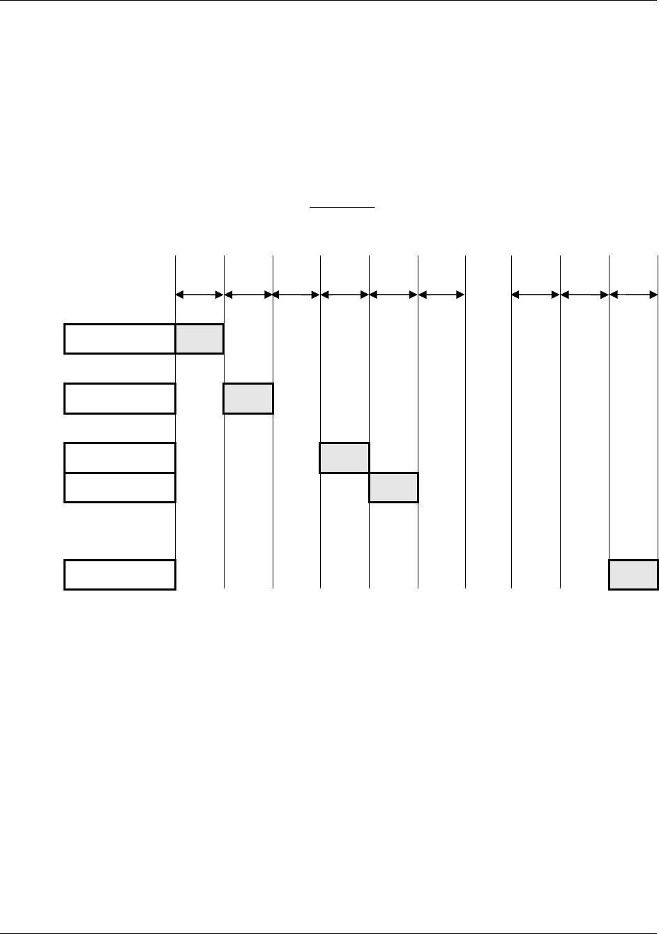
1508-USM-00-0-04 HF Multi ISO RFID Reader User Manual, Firmware V1.4
2.3.1.6.1 Time slotted answer
In party line mode, more than one reader can be used simultaneously. The time slotted answer
allows separating in time the answers from all connected devices. The station ID is used to
determine the correct time slot.
The reader supports up to 254 unique time slots. The following formula calculates the duration of
one time slot (only one baud rate is supported per party line):
6*
10
][
0Baudrate
sT
The following figure shows the timing diagram of time slotted answers.
Timeslot 0 1 2 3 4 5 … 252 253 254
T
0 T1 T2 T3 T4 T
5 T
252 T
253 T
254
HOST 'g'
Reader (01) 01
Reader (03) 03
Reader (04) 04
Reader (254) 254
2.3.1.6.2 Binary Protocol Version 2
This command never sends version 2 binary frames.
Page 44 of 144 August 2010
© 2005-2010 HID Global Corporation. All rights reserved.

HF Multi ISO RFID Reader User Manual, Firmware V1.4 1508-USM-00-0-04
2.3.1.7 High-speed select
This command selects a card in the antenna field (according to the selection criteria) or prepares
a multi-select command, switches to high baud rates and enables 256-byte frames. If execution is
successful, the command returns the UID of the selected card and the used baud rate. The reader
automatically detects the maximum frame size of the card. The reader also tries to communicate
to the transponder with the specified baud rate. If no communication is possible, the reader will
automatically decrease the speed to the next lower value.
In synchronous mode the up and downlink speed are identical.
In asynchronous mode the up and downlink speed can be different.
This command can also force the reader to the communication speed and frame size of the tag to
the specified values. This is only needed if the high-speed select is done manually with the
transfer command.
Command
Command Data
‘h’ Option byte (1 byte)
synchronous mode
00h … select a single card with 106kBaud
02h … select a single card with 212kBaud
04h … select a single card with 424kBaud
08h … select a single card with 848kBaud
10h … prepare next multi-select for 106kbaud
12h … prepare next multi-select for 212kbaud
14h … prepare next multi-select for 424kbaud
18h … prepare next multi-select for 848kbaud
20h … forces reader to 106kBaud
22h … forces reader to 212kBaud
24h … forces reader to 424kBaud
28h … forces reader to 848kBaud
tag size
30h – 38h … force tag frame size
asynchronous mode
80h … select a single card with 106kBaud
82h … select a single card with 212kBaud
84h … select a single card with 424kBaud
88h … select a single card with 848kBaud
90h … prepare next multi-select for 106kbaud
92h … prepare next multi-select for 212kbaud
94h … prepare next multi-select for 424kbaud
98h … prepare next multi-select for 848kbaud
A0h … forces reader to 106kBaud from tag to reader
A2h … forces reader to 212kBaud from tag to reader
A4h … forces reader to 424kBaud from tag to reader
A8h … forces reader to 848kBaud from tag to reader
August 2010 Page 45 of 144
© 2005-2010 HID Global Corporation. All rights reserved.

1508-USM-00-0-04 HF Multi ISO RFID Reader User Manual, Firmware V1.4
Command Data
B0h … forces reader to 106kBaud from reader to tag
B2h … forces reader to 212kBaud from reader to tag
B4h … forces reader to 424kBaud from reader to tag
B8h … forces reader to 848kBaud from reader to tag
Answer
Answer Description
Data (n bytes) +
frame size and
baud rate (1byte)
Serial number + frame size used and baud rate
'F' Error: General failure
‘N’ Error: No Tag in field [addressed tag not present or not responding]
Note: If the tag does not support ISO 14443 part 4 F0h will return after serial number instead of
used frame size/baud rate.
Examples
High-speed select
Command Description
h08 1234567890ABCD84
Select the card with UID 1234567890SABCD.
The card supports a 256-byte frame size and 424kBaud on the air interface.
High-speed multi-select
Command Description
h18
m1234567890ABCD<CR>
Prepare next multi-select for 848kBd
1234567890ABCD84
Select the card with UID 1234567890SABCD.
The card supports a 256-byte frame size and 424kBaud on the air
interface.
2.3.1.7.1 Answer from 0xh and 1xh
The lower nibble contains the baud rate used for the air interface.
Baud Rate Description
x0 106kBaud
x2 212kBaud
x4 424kBaud
x8 848kBaud
The higher nibble contains the frame size used for the air interface.
Frame Size Description
0x 16 Bytes
1x 24 Bytes
2x 32 Bytes
Page 46 of 144 August 2010
© 2005-2010 HID Global Corporation. All rights reserved.

HF Multi ISO RFID Reader User Manual, Firmware V1.4 1508-USM-00-0-04
Frame Size Description
3x 40 Bytes
4x 48 Bytes
5x 64 Bytes
6x 96 Bytes
7x 128 Bytes
8x 256 Bytes
2.3.1.7.2 Answer from 8xh
The lower nibble contains the baud rate used for the air interface.
The value for the baud rate is XORed with the used up and downlink speed.
Baud Rate Description
x1 106kBaud
x2 212kBaud
x4 424kBaud
x8 848kBaud
The higher nibble contains the frame size used for the air interface.
Frame Size Description
0x 16 Bytes
1x 24 Bytes
2x 32 Bytes
3x 40 Bytes
4x 48 Bytes
5x 64 Bytes
6x 96 Bytes
7x 128 Bytes
8x 256 Bytes
2.3.1.7.3 Answer from 2xh, 3xh, 9xh, Axh and Bxh
The option byte is returned as the answer.
2.3.1.7.4 Select a single tag
No previous continuous read is required. The command executes an automatic field reset.
2.3.1.7.5 Extended ID
See Protocol Configuration 3 (1Bh), page 33 for more information on Extended ID.
The RATS answer is inserted between the serial number and baud rate / frame size byte for
ISO14443 A tags.
August 2010 Page 47 of 144
© 2005-2010 HID Global Corporation. All rights reserved.

1508-USM-00-0-04 HF Multi ISO RFID Reader User Manual, Firmware V1.4
2.3.1.7.6 Multiple tags
This command with parameter 1xh prepares the next multi-select command as a high-speed
select. Any other command will disable the preparation.
2.3.1.7.7 RATS Guard Time SFGT
A high-speed select with parameters 0xh and 1xh automatically waits the SFGT guard time
received from the tag before sending the PPS command.
2.3.1.8 High Speed Select Wait
There are two command variants – ‘hc’ and ‘hw’. If one or more tag(s) are present, return both the
selected UID and in the case of multiple tags, also report that a collision was detected, reducing
the host processing overhead.
The ‘hw’ command additionally allows specific Reset off and Reset recovery times to be set,
without altering the Register values, and will search tags for a specified time, further reducing the
host processing overhead.
Command
Command Data
‘hc’ Option byte
‘hw’ Option byte, Reset Off time, Reset Recovery time, Wait time
Answer
Answer Description
Data (n bytes) + frame size and
baud rate (1byte) + collision flag Serial number + frame size used and baud rate [+ collision flag]
'F' Error: General failure
‘N’ Error: No tag in field [addressed tag not present or not
responding]
Note: If the selected tag does not support ISO 14443 part 4, instead of the used frame size/baud
rate byte being returned after the UID, the command will return byte F0h.
Examples
Command Description
hc88 04 91 DF E9 F1 02 80 F0 08
Responding tag doesn’t support ISO14443-4 – hence FO – and multiple cards were detected – 08
04 22 0F 14 4B 1C 80 58
Responding tag supports a 64-byte frame size and 848kBaud on the air interface - 58
hc88
04 91 DF E9 F1 02 80 F0 08
Responding tag doesn’t support ISO14443-4 – hence FO – and multiple cards were detected – 08
hw88 0A 20 32
04 22 47 14 4B 1C 80 84
Responding tag supports a 256-byte frame size and 424kBaud on the air interface – 84
hw88 0A 20 32
hw88 0A 20 32 ‘N’
After a reset/recovery period, the reader searched for tags for 200mS (4 * 32h). None found.
Page 48 of 144 August 2010
© 2005-2010 HID Global Corporation. All rights reserved.
HF Multi ISO RFID Reader User Manual, Firmware V1.4 1508-USM-00-0-04
Option
See High-speed select, page 45 for a full description of this byte.
Reset Off
The length of time the field is switched off
Reset Recovery
The time for the field to stabilize after being switched on
Wait
The length of time in mS * 4 the reader will search for tags (19h = 25 * 4 = 100mS)
Note: A zero wait time is not supported by the reader.
2.3.1.9 Lock Block
This command locks a block permanently. Only SR176 and ISO 15693 tags are supported.
Command
Command Data
'k' Block address (1 byte)
Answer
Answer Description
Data 'K' + page address
'F' Error: Lock failure
'N' Error: No tag in field [addressed tag not present or not responding]
'O' Error: Operation mode failure [tag is neither SR176 or ISO 15693 compliant]
'X' Error: Block already locked
Example
Command Description
k05 K05
Lock block 05.
2.3.1.9.1 Apply settings
After locking a block permanently, the tag needs to be selected for the settings to apply.
August 2010 Page 49 of 144
© 2005-2010 HID Global Corporation. All rights reserved.

1508-USM-00-0-04 HF Multi ISO RFID Reader User Manual, Firmware V1.4
2.3.1.10 Multi-Tag Selection / List
This command detects several tags at the same time. It replaces the fast select command ('s') in
multiple tag surroundings. The Multi-Tag List command lists all tags with their serial numbers. Use
the Multi-Tag Select command to select a single tag. Each tag has to be selected separately.
Command
Command Data
'm' Serial number (n bytes)
<CR> (1 byte)
Answer
Answer Description
Data serial number
'N' Error: No Tag in the field [addressed tag not present or not responding]
Example
Command Description
m<CR> 04E9E700000000 first card
34030F07 second card
02 number of detected tags
m04E9E700000000<CR> Select card with its serial number
2.3.1.10.1 Multi-tag list
Sending a <CR> as the first parameter, the reader returns a list of all tags present in the antenna
field. In the end the total number of tags detected is returned.
2.3.1.10.2 Reading distance
Each card needs a specific amount of power. The reader always provides the same power level.
Therefore, the reading distance will decrease if more tags are present. Basically, the reading
distance depends on the tag, the antenna and the tuning of the antenna.
2.3.1.10.3 Multi-tag select
Using the serial number with <CR> as parameter, the corresponding tag will be selected. High-
level interactions can be performed addressing only this card. All other tags remain silent.
2.3.1.10.4 Multi-tag reset
The antenna field reset can be deactivated with the Protocol configuration 2 register.
By suppressing the antenna field reset, it is possible to detect only new tags in the antenna field.
CAUTION: Possibly, ISO 15693 tags are interfered from ISO14443 type B and SR 176 tags.
In this case, the ISO 15693 tag always answers on a multi list command even if there was
no previous field reset. In this case, deactivate ISO 14443 B and SR 176 tags.
Page 50 of 144 August 2010
© 2005-2010 HID Global Corporation. All rights reserved.
HF Multi ISO RFID Reader User Manual, Firmware V1.4 1508-USM-00-0-04
2.3.1.10.5 Maximum number of tags
The maximum number of tags in the antenna field is limited to 64 and by the physical
characteristics of the antenna.
2.3.1.10.6 LED activity
The LED stays green as long as a tag was found and goes dark if the command is finished.
2.3.1.11 Switch on/off CTS
This command switches on/off the usage of CTS. If switched on, the reader only answers if CTS
is low. Ensure the hardware supports CTS before using this command
Command
Command Data
‘o&’ Data (1 byte) 00h = off; 01h = on
Answer
Answer Description
Data (1 byte) New status of CTS 00h = off; 01h = on
2.3.1.12 921 kBaud COM Select
This command switches the serial COM speed to 921 Kbaud. The actual COM speed is 968571
baud due to the reader’s crystal frequency. The host application should match this actual speed in
order to minimize transmission errors. The reader response to this command is to issue the reply
0xC0 0x03, then switch to 921 Kbaud. The host, having received this reply, switches its COM
speed to 921 Kbaud.
After a reset command, the reader re-opens communications at the stored baud rate. The 921
Kbaud setting is not stored, so the reader cannot open at this speed. The host either remembers
the original COM speed or auto-detects the reader settings.
Command
Command Data
‘o#’
Answer
Answer Description
C0h 03h Select High Speed acknowledge
August 2010 Page 51 of 144
© 2005-2010 HID Global Corporation. All rights reserved.
1508-USM-00-0-04 HF Multi ISO RFID Reader User Manual, Firmware V1.4
2.3.1.13 Include Tag Type
This command includes a specific tag type to those addressed by the reader device.
Command
Command Data
‘o+’ Tag type (1 byte)
Answer
Answer Description
'O+' + tag type (1 byte) Command code + String of tag type
Tag type character
Refer to Set tag type, page 53.
Example
Command Description
o+a Include ISO14443-A to the tag types addressed by the reader
2.3.1.14 Exclude tag type
This command excludes a specific tag type from being addressed by the reader device.
Command
Command Data
‘o-’ Tag type (1 byte)
Answer
Answer Description
'O-' + tag type (1 byte) Command code + String of tag type
Tag type character
Refer to Set tag type, page 53.
Example
Command Description
o-a Exclude ISO14443-A from the tag types addressed by the reader
Page 52 of 144 August 2010
© 2005-2010 HID Global Corporation. All rights reserved.

HF Multi ISO RFID Reader User Manual, Firmware V1.4 1508-USM-00-0-04
2.3.1.15 Set tag type
This command sets up the reader for a specific tag type. The continuous read function will speed
up because only this type of tag is addressed. After a reset, the reader starts as defined in its
start-up configuration.
Command
Command Data
'o' ISO type (1 byte)
'a' … ISO 14443 Type A
'b' … ISO 14443 Type B
'd' … ICODE UID
'e' … ICODE EPC
'i' … ICODE
's' … SR176
't' … activate all tags
'v' ... ISO 15693
Answer
Answer Description
'OA'
'OB'
'OD'
'OE'
'OI'
'OS'
'OT'
'OV'
String of tag type
Example
Command Description
oa Sets the reader device to address ISO14443-A type tags.
Innovision Jewel tag
Innovision Jewel tag is part of ISO 14443 Type A. It can not be separately switched on/off.
August 2010 Page 53 of 144
© 2005-2010 HID Global Corporation. All rights reserved.
1508-USM-00-0-04 HF Multi ISO RFID Reader User Manual, Firmware V1.4
2.3.1.16 Set Configuration Flags
This command allows setting some configuration flags just in time; no reset is needed. The values
are not stored in the EEPROM; therefore, the changed values are not available after a reset.
Command
Command Data
of flag type (1 byte)
data (1 byte)
Answer
Answer Description
Data (1 byte) Current state of changed flag.
'R' Error: Out of range
Example
Command Description
of 01 01 Answer: 01
Enables the New Serial Mode flag.
Page 54 of 144 August 2010
© 2005-2010 HID Global Corporation. All rights reserved.

HF Multi ISO RFID Reader User Manual, Firmware V1.4 1508-USM-00-0-04
Flag Types
The following table shows the Flag Type with its corresponding flag from the specified Protocol
Configuration Register.
Table 26 Flag Type with corresponding flag
Flag Type Corresponding Flag Protocol Configuration
Register Valid
values
00h Multitag 1 00 / 01
01h New Serial Mode 1 00 / 01
02h LED 1 00 / 01
03h Single Shot 1 00 / 01
04h Extended Protocol 1 00 / 01
05h Extended ID 1 00 / 01
06h Disable Multitag Reset 2 00 / 01
07h Noisy Environment 2 00 / 01
08h Reset Recovery Time Multiplier 2 00 … 03
09h Enable ISO14443 B Anti-collision 2 00 / 01
0Ah Disable ISO14443-4 Error Handling 2 00 / 01
0Bh Disable automatic
ISO14443-4 timeouts 3 00 / 01
0Dh Page Read 3 00 / 01
0Eh NoRxSOF 3 00 / 01
0Fh NoRxEGT 3 00 / 01
10h NoRxEOF 3 00 / 01
11h ReqA Extended ID 3 00 / 01
12h Disable Read after Write 4 00 / 01
13h SAK Extended ID 3 00 / 01
14h WupA/B 4 00 / 01
15h CID Extended ID 4 00 / 01
16h Internal use / Do not change
2.3.1.16.1 Out of range failure 'R'
The entered flag type is out of range.
August 2010 Page 55 of 144
© 2005-2010 HID Global Corporation. All rights reserved.
1508-USM-00-0-04 HF Multi ISO RFID Reader User Manual, Firmware V1.4
2.3.1.17 Set Configuration Register
This command allows setting some configuration registers just in time; no reset is needed. The
values are not stored in the EEPROM; therefore the changed values are not available after a
reset.
Command
Command Data
Og Register type (1 byte)
data (1 byte)
Answer
Answer Description
Data (1 byte) Current state of changed register.
'R' Error: Out of range [entered register value is out of range]
Example
Command Description
og0450 Answer: 50
Sets the Reset Recovery Time to 50h.
Register Types
The following table shows the Register Type with its corresponding register.
Table 8 - Register Type with Corresponding Register
Register Type Corresponding Register
00h Single shot time-out value
01h TMR low
02h TMR high
03h Reset Off Time
04h Reset Recovery Time
05h ISO 14443A Selection Time-out
06h ISO 14443B Selection Time-out
07h SR176 Selection Time-out
08h AFI
09h Modulation conductance
0Ah Threshold
0Ch Page Read Start
0Dh Page Read Number
0Eh Command Guard Time
0Fh CID
10h Internal use / Do not change
Page 56 of 144 August 2010
© 2005-2010 HID Global Corporation. All rights reserved.

HF Multi ISO RFID Reader User Manual, Firmware V1.4 1508-USM-00-0-04
2.3.1.18 Set target modulation conductance register
This command allows switching to a different modulation conductance register. On startup,
modulation conductance register 0 is used.
When more than one antenna is used, it may be necessary to use different modulation
conductance values for different antennas. Switching registers does not require knowledge of the
actual values used.
Ensure that Modulation Conductance registers 1-3 are initialized before using this feature.
Command
Command Data
om Target modulation conductance register (1 byte) Valid range 00h – 03h
Answer
Answer Description
Data (2 bytes) Target modulation conductance register (1 byte); register value (1 byte)
‘R’ Error: Out of range [selected register is out of range]
2.3.1.19 Reread all registers
This command rereads and applies all register settings.
Command
Command Data
Ox none
Answer
Answer Description
Data (3 bytes) 'X' + new protocol + new baud rate
Example
Command Description
Ox Answer: X0106
binary protocol and 460800 baud active
New protocol
00h means ASCII and 01h means binary protocol.
New baud rate
Values of 00h-06h are valid. For baud rate values refer to
August 2010 Page 57 of 144
© 2005-2010 HID Global Corporation. All rights reserved.

HF Multi ISO RFID Reader User Manual, Firmware V1.4 1508-USM-00-0-04
2.3.1.20 Antenna power on/off
This command controls the antenna power. It can be used to decrease the power consumption of
the reader.
Command
Command Data
'pon' Switch reader on
'poff' Put reader in standby mode
Answer
Answer Description
'P' Positive acknowledge
Example
Command Description
Poff Put reader in standby mode
2.3.1.20.1 Power off
The reader enters standby mode. Power consumption is decreased. All tags in the antenna field
are powered off and reset. Standby mode is only entered manually.
To switch off the whole unit, pin 16 (Enable) has to be set to logic low.
2.3.1.20.2 Power on
The reader leaves standby mode and is ready for the next command. Sending a tag command
(i.e. select, continuous read) the reader is powered up.
2.3.1.21 Read/Write User Port
This command sets or reads the state of the user port (pin 14) of the OEM reader device. The port
is set either as output or as input. If set to output, see notes in Jumper 2 Details, page 14
regarding current limiting to prevent reader damage.
Command
Command Data
'pr' None
'pw' State of user port (1 Byte)
Answer
Answer Description
Data State of user port (1 Byte)
'C' Error: Error correction fails
'F' Error: Transmission Error / No answer received
August 2010 Page 59 of 144
© 2005-2010 HID Global Corporation. All rights reserved.

1508-USM-00-0-04 HF Multi ISO RFID Reader User Manual, Firmware V1.4
Example
Command Description
Pr Reads user port
pw01 Sets user port state to high
2.3.1.21.1 Read port
The port read command returns the current state of the USER port.
Port state Description
00h USER port is low
01h USER port is high
2.3.1.21.2 Write port
If user port is used as an output, a 1k resistor has to be fitted in series with the port pin to limit
the current, otherwise the reader device can be damaged.
Port state Description
00h Sets USER port to low
01h Sets USER port to high
02h – 7Fh RFU
80h – FFh Sends a serial data frame and checks the received frame
Sending a Data Frame
If the highest bit (MSB) is set in the State of the User Port, the command sends a serial data
frame out the USER port.
The frame includes a start bit, 8 data bits, parity bit and a stop bit.
Table 9 - Sending Serial Data Frame
Transmit
Frame Description
Low Start bit
Low RFU
Data Bit 6 State of the User Port Bit 6
Data Bit 5 State of the User Port Bit 5
Data Bit 4 State of the User Port Bit 4
Data Bit 3 State of the User Port Bit 3
Data Bit 2 State of the User Port Bit 2
Data Bit 1 State of the User Port Bit 1
Data Bit 0 State of the User Port Bit 0
Parity Bit Even Parity Bit
High Stop Bit
Page 60 of 144 August 2010
© 2005-2010 HID Global Corporation. All rights reserved.
HF Multi ISO RFID Reader User Manual, Firmware V1.4 1508-USM-00-0-04
After 2ms Guard Time the answer should be received on the User Port otherwise an error is
returned.
Table 10 - Receiving Serial Data Frame
Receive
Frame Description
Low Start bit
Error Bit If set, an error was detected.
Data Bit 6 State of the User Port Bit 6
Data Bit 5 State of the User Port Bit 5
Data Bit 4 State of the User Port Bit 4
Data Bit 3 State of the User Port Bit 3
Data Bit 2 State of the User Port Bit 2
Data Bit 1 State of the User Port Bit 1
Data Bit 0 State of the User Port Bit 0
Parity Bit Even Parity Bit
High Stop Bit
If the Error bit is set or the Parity Bit is not correct, the Write User Port command returns an error
code.
2.3.1.22 Quiet
This command sets a selected tag into halt state. Only ISO14443 A+B and SR176 tags are
supported.
Command
Command Data
'q' None
Answer
Answer Description
'Q' Halt state successfully set.
'N' Error: No Tag in the field [addressed tag not present or not responding]
2.3.1.22.1 ISO 14443 Type A
With ISO14443-3 Type A tags, the Quiet command always answers with 'Q' because the halt
command does not send any acknowledge.
In Part 4 a 'Deselect' command will be performed.
2.3.1.22.2 ISO 14443 Type B
Some ISO14443 Type B tags do not support this command or do not respond. ‘Quiet’ is an ISO
14443-4 command, so it will work only if the ‘Deselect’ command is supported by the
corresponding transponder.
2.3.1.22.3 SR176
With SR176 tags the Quiet command always answer with 'Q' because the completion command
does not send any acknowledge.
August 2010 Page 61 of 144
© 2005-2010 HID Global Corporation. All rights reserved.
1508-USM-00-0-04 HF Multi ISO RFID Reader User Manual, Firmware V1.4
2.3.1.23 Resend Last Answer
This command resends the last answer from the internal serial buffer of the reader.
Command
Command Data
'ra' Resend last answer
2.3.1.24 Read block
This command reads a data block on a card. The size of the returned data depends on the tag
used. The block address range depends on the tag as well.
Command
Command Data
'r' Block address (1 byte), valid range 00h – 40h
'rb' Block address (1 byte)
Answer
Answer Description
Data data block (depends on tag type)
'F' Error: read failure [bad data or address range error]
'N' Error: No tag in field [addressed tag not present or not responding]
'O' Error: Operation mode failure
'R' Error: Out of range
Example
Command Description
rb05 Reads block 05.
2.3.1.24.1 Operation mode failure 'O'
The presented tag is not ISO14443 type A, SR 176, ICode, ICode-UID and ISO 15693 compliant.
For ISO 14443 type A only MIFARE tags are supported.
This error also appears if the reader is not correctly configured.
2.3.1.24.2 Out of range failure 'R'
The block address of the 'r' command is higher than 40h.
The block address of the 'r' command conflicts with other commands, therefore the block address
has to be limited to 40h.
Use the 'rb' command instead.
Page 62 of 144 August 2010
© 2005-2010 HID Global Corporation. All rights reserved.
HF Multi ISO RFID Reader User Manual, Firmware V1.4 1508-USM-00-0-04
2.3.1.25 Read data (multiple blocks)
This command reads multiple data blocks on a card. The size of the returned data depends on the
tag used. The block address range depends on the tag as well.
Command
Command Data
'rd' Start block address (1 byte)
Number of blocks to read (1 byte)
Answer
Answer Description
Data data block (depends on tag type)
'F' Error: read failure [bad data or address range error]
'N' Error: No tag in field [addressed tag not present or not responding]
'O' Error: Operation mode failure
Example
Command Description
rd0504 Reads 4 blocks starting with block 05.
2.3.1.25.1 Operation mode failure 'O'
The presented tag is not ISO14443 type A, SR 176, ICode or ISO 15693 compliant.
For ISO 14443 type A only MIFARE tags are supported.
2.3.1.26 Read reader EEPROM
This command reads the internal reader EEPROM. It contains all start-up parameters and the
device ID. Changes in the start-up settings will only go into effect after a reset of the device.
Command
Command Data
'rp' EEPROM address (1 byte) 00h … EFh
Answer
Answer Description
Data EEPROM data (1 byte)
'R' Error: Out of range failure [entered address is not valid]
Example
Command Description
rp0B Reads protocol configuration register.
August 2010 Page 63 of 144
© 2005-2010 HID Global Corporation. All rights reserved.

1508-USM-00-0-04 HF Multi ISO RFID Reader User Manual, Firmware V1.4
2.3.1.27 Select
This command selects a single card in the antenna field. It can only be used in single tag mode. If
successfully executed, the command returns the UID of the selected card. The reader detects the
length of the UID automatically.
Command
Command Data
's' None
Answer
Answer Description
Data serial number
'N' Error: No Tag in the field [addressed tag not present or not responding]
Example
Command Description
S 1234567890ABCD
Select the card with UID 1234567890SABCD.
2.3.1.27.1 Select a single tag
No previous continuous read is required. The command executes an automatic field reset.
2.3.1.27.2 Extended ID
See
Page 64 of 144 August 2010
© 2005-2010 HID Global Corporation. All rights reserved.
HF Multi ISO RFID Reader User Manual, Firmware V1.4 1508-USM-00-0-04
Protocol Configuration 1 (0Bh), page 25 for more information on Extended ID.
2.3.1.27.3 Multiple tags
This command is designed for fast access of a single tag in the field. If multiple cards are used the
'm' instruction has to be used instead.
2.3.1.28 Get Version
This command returns the current version of the reader module.
Command
Command Data
'v' None
Answer
Answer Description
'MultiISO 1.0' + <CR> + <LF> ASCII Mode
02 00 0C 4D 75 6C 74 69 49 53 4F 20 31 2E 30 1F 03 Binary Mode
Example
Command Description
V ‘MultiISO 1.0’
Version of the reader module
2.3.1.29 Write block
This command writes data to a block.
Command
Command Data
'w' Block address (1 byte), valid range 00h – 40h
Data (n bytes)
'wb' Block address (1 byte)
Data (n bytes)
Answer
Answer Description
Data Data block (depends on tag type)
'F' Error: Write failure [bad transmission conditions or address range error]
'N' Error: No tag in field [addressed tag not present or not responding]
'O' Error: Operation mode failure
'R' Error: Out of range
Example
Command Description
wb0511223344 Writes data 11223344 on block 05.
2.3.1.29.1 Operation mode failure 'O'
August 2010 Page 65 of 144
© 2005-2010 HID Global Corporation. All rights reserved.

1508-USM-00-0-04 HF Multi ISO RFID Reader User Manual, Firmware V1.4
The presented tag is not ISO14443 type A, SR 176, ICode, ICode-UID and ISO 15693 compliant.
For ISO 14443 type A only MIFARE tags are supported.
2.3.1.29.2 Out of range failure 'R'
The block address of the 'w' command is higher than 40h.
The block address of the 'w' command conflicts with other commands, therefore the block address
has to be limited to 40h.
Use the 'wb' command instead.
2.3.1.29.3 Disable Read after Write
A read is done automatically after every write to ensure correct writing.
If the "disable Read after Write flag" is set no read is done, and the returned data is a 00h byte in
case of successfully written data.
Page 66 of 144 August 2010
© 2005-2010 HID Global Corporation. All rights reserved.

HF Multi ISO RFID Reader User Manual, Firmware V1.4 1508-USM-00-0-04
2.3.1.30 Write data (multiple blocks)
This command writes multiple blocks to a card.
Command
Command Data
'wd' Start block address (1 byte)
Number of blocks (1 byte)
Data (n bytes)
Answer
Answer Description
Data Data block (depends on tag type)
'F' Error: Write failure [bad transmission conditions or address range error]
'N' Error: No tag in field [addressed tag not present or not responding]
'O' Error: Operation mode failure
Example
Command Description
wd050211223344556
67788 Writes data 11223344 on block 05 and 55667788 on block 06.
2.3.1.30.1 Operation mode failure 'O'
The presented tag is not ISO14443 type A, SR 176, ICode or ISO 15693 compliant.
For ISO 14443 type A only MIFARE tags are supported.
2.3.1.30.2 Disable Read after Write
A read is done automatically after every write to ensure correct writing.
If the "disable Read after Write flag" is set no read is done, and the returned data is a 00h byte in
case of successfully written data.
August 2010 Page 67 of 144
© 2005-2010 HID Global Corporation. All rights reserved.
1508-USM-00-0-04 HF Multi ISO RFID Reader User Manual, Firmware V1.4
2.3.1.31 Write EEPROM
Writes to the internal reader EEPROM. It contains all start-up parameters and the device ID.
Changes to the start-up settings will only go into effect after a reset of the device.
Command
Command Data
'wp' Address (1 byte), valid range 0Ah - EFh
Data (1 byte)
Answer
Answer Description
Data EEPROM data (1 byte)
'F' Error: Read after write failure
'R' Error: Out of range failure [entered address exceeds the address range]
Example
Command Description
wp0A01 Set EEPROM address 0A (Station ID) to 01h
2.3.1.32 Reset
This command executes a power on (software) reset. New configuration settings will be loaded. It
resets all tags in the antenna field.
Command
Command Data
'x' None
Answer
Answer Description
‘MultiISO 1.2' + <CR> + <LF> ASCII Mode
None Binary Mode
2.3.1.32.1 Disable Start-up Message
If the start-up message is disabled in the protocol configuration 2 register, the ASCII mode does
not respond with the version of the reader.
2.3.1.32.2 Reset Timing
The power up timing depends on environmental conditions such as voltage ramp up. For
handheld devices the timing can vary based on the charge state of the battery.
Page 68 of 144 August 2010
© 2005-2010 HID Global Corporation. All rights reserved.

HF Multi ISO RFID Reader User Manual, Firmware V1.4 1508-USM-00-0-04
2.3.1.33 Field Reset
The field reset switches off the antenna field for the specified duration. All tags need a certain
amount of time to initialize before a command can be processed. The second byte specifies the
field recovery time.
Command
Command Data
'y' Off time in milliseconds (1 byte)
Field recovery time in milliseconds (1 byte)
Answer
Answer Description
'Y' After the field reset the reader sends back a ‘Y’ to acknowledge the command.
August 2010 Page 69 of 144
© 2005-2010 HID Global Corporation. All rights reserved.
1508-USM-00-0-04 HF Multi ISO RFID Reader User Manual, Firmware V1.4
2.3.2 ISO 14443 Type A (MIFARE ®) only commands
2.3.2.1 Increment value block (credit)
Increments a value block with a defined value. A read is done automatically after a write to verify
data integrity. The command fails if the source block is not in value block format. A previous login
is needed to access a block.
Command
Command Data
'+' Block # (1 byte); Value (4 bytes)
Answer
Answer Description
Data Value (4 bytes)
'I' Error: value block failure
'F' Error: increment failure or inability to read after write
'N' Error: No tag in field [addressed tag not present or not responding]
'O' Error: Operation mode failure [tag is not ISO14443 type A compliant]
Example
Command Description
+0400000001 Adds 1 to value block 4
+0500000100 Adds 256 to value block 5
2.3.2.1.1 No value block 'I'
Specified block does not match the value format. The value block is corrupted. A backup block
can be used to restore the correct value.
Page 70 of 144 August 2010
© 2005-2010 HID Global Corporation. All rights reserved.
HF Multi ISO RFID Reader User Manual, Firmware V1.4 1508-USM-00-0-04
2.3.2.2 Decrement value block (debit)
Decrements a value block with a defined value. A read is done automatically after the write to
verify data integrity. The command fails if the source block is not in value block format. A previous
login is needed to access a block.
Command
Command Data
'-' Block (1 byte)
Value (4 bytes)
Answer
Answer Description
Data Value (4 bytes)
'I' Error: value block failure
'F' Error: decrement failure or inability to read after write
'N' Error: No tag in field [addressed tag not present or not responding]
'O' Error: Operation mode failure [tag is not ISO14443 type A compliant]
Example
Command Description
-0400000001 Subtract 1 to value block 4
-0500000100 Subtract 256 to value block 5
2.3.2.2.1 No value block 'I'
Specified block does not match the value format. The value block is corrupted. A backup block
can be used to restore the correct value.
2.3.2.3 Copy value block (backup)
Copies a value block to another block of the same sector. A read is done automatically after the
write to ensure data integrity. Used for backup and error recovery. A previous login is needed to
access a block.
Command
Command Data
'=' Source block (1 byte)
Target block (1 byte)
Answer
Answer Description
Data New value of target block (4 bytes).
'I' Error: value block failure
'F' Error: copy failure or inability to read after write
'N' Error: No tag in field [addressed tag not present or not responding]
'O' Error: Operation mode failure [tag is not ISO14443 type A compliant]
August 2010 Page 71 of 144
© 2005-2010 HID Global Corporation. All rights reserved.

1508-USM-00-0-04 HF Multi ISO RFID Reader User Manual, Firmware V1.4
Example
Command Description
=0405 Copy value block 4 to block 5
=0506 Copy value block 5 to block 6
2.3.2.3.1 Target block
The target block does not need to be a valid value block. If the source block is not in value format,
the command fails.
2.3.2.3.2 No value block 'I'
Source value block is not in a valid value block. The value block is corrupted. A backup block can
be used to restore the correct value.
2.3.2.4 Login (authenticate tag)
Performs an authentication in order to access one sector of a MIFARE card. Only one sector can
be accessed at a time.
Command
Command Data
'l' Sector (1 byte), valid range 00h - 3Fh
Key type (1 byte)
AAh authenticate with key type A
FFh authenticate with key type A, transport key
FFFFFFFFFFFFh
BBh authenticate with key type B
10h … 2Fh authenticate with key type A using stored
key (00h … 1Fh)
30h … 4Fh authenticate with key type B using stored
key (00h … 1Fh)
Key (6 bytes) / <CR> (1 byte), optional
By transmitting <CR> instead of the key data
authentication is done with manufacturer’s transport
keys (A0A1A2A3A4A5h, B0B1B2B3B4B5h,
FFFFFFFFFFFFh).
Answer
Answer Description
data Login status (1 byte)
'L' Login success
'F' Error: General failure
'N' Error: No tag in field [addressed tag not present or not responding]
'O' Error: Operation mode failure [tag is not ISO14443 type A compliant]
'R' Error: Out of range [entered key type or the sector is out of range]
'X' Error: Authentication failed
Page 72 of 144 August 2010
© 2005-2010 HID Global Corporation. All rights reserved.

HF Multi ISO RFID Reader User Manual, Firmware V1.4 1508-USM-00-0-04
Example
Command Description
l02AA<CR> Authenticate for sector 2, using the transport key A
(A0A1A2A3A4A5h, key type A)
l3FBB<CR> Authenticate for sector 63, using the transport key 2
(B0B1B2B3B4B5h, key type B)
l04FF<CR> Authenticate for sector 4, using the transport key 3
(FFFFFFFFFFFFh, key type A)
l0FAAFFFFFFFFFFFF Authenticate for sector 15, using key FFFFFFFFFFFFh, key type A
l0E14 Authenticate for sector 14, using EEPROM key 4, key type A
l0530 Authenticate for sector 5, using EEPROM key 0, key type B
l0732 Authenticate for sector 7, using EEPROM key 2, key type B
l0110 Authenticate for sector 1, using EEPROM key 0, key type A
l0ABBFF12FFFFFF35 Authenticate for sector 10, using key FF12FFFFFF35h, key type B
2.3.2.4.1 <CR>
Three transport keys are implemented to access cards quickly.
By transmitting <CR> instead of the key, the reader module uses the transport keys for the login
procedure.
Command Description
LxxAA<CR> Authenticate for sector xx, using the transport key 1
(A0A1A2A3A4A5h, key type A)
LxxBB<CR> Authenticate for sector xx, using the transport key 2
(B0B1B2B3B4B5h, key type B)
LxxFF<CR> Authenticate for sector xx, using the transport key 3
(FFFFFFFFFFFFh, key type A)
2.3.2.4.2 Login with key data from EEPROM
Each key stored in the reader EEPROM can be used as type A or type B key. To use a key as
type A, the value 10h must be added to the key index. 30h must be added to use a key as type B.
2.3.2.4.3 Usage of key A, key B
MIFARE cards support two different crypto keys for each sector. Each key is 32 bits long and is
stored in the sector trailer (last block of the sector) on the card. It is possible to set different access
rights for each key.
August 2010 Page 73 of 144
© 2005-2010 HID Global Corporation. All rights reserved.

1508-USM-00-0-04 HF Multi ISO RFID Reader User Manual, Firmware V1.4
2.3.2.5 Read value block
Reads a value block. The command checks if data is in value block format. The read value block
command needs a successful login.
Command
Command Data
'rv' Value block (1 byte)
Answer
Answer Description
Data Read value (4 bytes)
'F' Error: General failure due to bad transmission conditions or address not authenticated
'I' Error: value block failure
'N' Error: No tag in field [addressed tag not present or not responding]
'O' Error: Operation mode failure [tag is not ISO14443 type A compliant]
Example
Command Description
rv04 Reads value of block 4.
2.3.2.5.1 No value block 'I'
The value read back after the write value command is not a value block. Data was corrupted.
2.3.2.6 Write value block
This command formats a block as a value block containing a 32-bit value. Value blocks need a
complete 16-byte block due to redundant storage. A successful login is required to run the
command.
Command
Command Data
'wv' Value block (1 byte); Value (4 bytes)
Answer
Answer Description
Data Written value (4 bytes)
'I' Error: value block failure
'F' Error: write failure due to bad transmission conditions or address not authenticated
'N' Error: No tag in field [addressed tag not present or not responding]
'O' Error: Operation mode failure [tag is not ISO14443 type A compliant]
Page 74 of 144 August 2010
© 2005-2010 HID Global Corporation. All rights reserved.

HF Multi ISO RFID Reader User Manual, Firmware V1.4 1508-USM-00-0-04
Example
Command Description
wv05010055EF Writes value 010055EFh to block 5.
2.3.2.6.1 Invalid value 'I'
The value read back after the write value command is not a value block. The data written was
corrupt.
2.3.2.6.2 Writing values
The write value block command is designed to create blocks in value format. This command
requires write access to the specified block. Using this instruction for ticketing operations is not
recommended. For ticketing applications, special instructions (Increment/Decrement/Copy) are
available.
2.3.2.6.3 Disable Read after Write
A read is done automatically after every write to ensure correct writing.
If the "disable Read after Write flag" is set no read is done, and the returned data is a 00h byte in
case of successfully written data.
August 2010 Page 75 of 144
© 2005-2010 HID Global Corporation. All rights reserved.

1508-USM-00-0-04 HF Multi ISO RFID Reader User Manual, Firmware V1.4
2.3.3 Key Management
The Key Management is able to store up to 32 keys and is also able to manage 3 different key
types. If no key is available to login into the reader, it is possible to reset the key table without any
authentication.
Key type Description
01 my-d™ secure key
02 DES key
03 MIFARE key
2.3.3.1 Authenticate to reader
This command logs into a reader. Only my-d™ secure and DES keys are allowed to login into
reader. After successful log in the key table of the reader can be changed. The authentication
does 2 two-pass authentications, defined in ISO 9798 part 2, within two steps. Following
commands need a prior log in:
Update key
Update key access rights
Change key type
Reset key table
Command
Command Data
Step 1: 'ar' Option x1h (1 byte)
Key type (1 byte)
Key index (1 byte)
Step 2: 'ar' Option x2h (1 byte)
Random number key Management (8 bytes)
MAC key Management (8 bytes)
Answer
Answer Description
Step 1 Random number reader (8 bytes)
Step 2 MAC reader (8 bytes)
Page 76 of 144 August 2010
© 2005-2010 HID Global Corporation. All rights reserved.

HF Multi ISO RFID Reader User Manual, Firmware V1.4 1508-USM-00-0-04
Option
The option byte defines the authentication step and type of authentication.
Bit Description
0 – 1 Authentication Steps
0: Log out
1: Step 1
2: Step 2
2 – 6 RFU
7 Authentication Algorithm
0: 2 two pass authentications
1: RFU
Key index
The key index of Step 1 points to a valid key with the access rights to login into the reader.
The key index is zero based.
Log out
It is possible to log out with Authentication Step 0.
Default Keys
The following keys are default:
Key Type Key
my-d™ 01020407080B0D0E10131516191A1C1Fh
Default Master key
DESFire 00000000000000000000000000000000h
MIFARE ® A0A1A2A3A4A5h
MIFARE ® B0B1B2B3B4B5h
MIFARE ® FFFFFFFFFFFFh
August 2010 Page 77 of 144
© 2005-2010 HID Global Corporation. All rights reserved.
1508-USM-00-0-04 HF Multi ISO RFID Reader User Manual, Firmware V1.4
Two-Pass Authentication Flow Diagram
Host Reader
1. Start Authentication Step 1 StartAuth
2. Generate Random number RndRdr
RndRdr 3. Reply Random number
4. Generate Random number RndH
5. Calculate the MAC of the key management
MacH = Enc(RndRdr)
6. Transmit Random number and MAC:
RndKm,MacH RndKm,MacH
7. Check the received MacH
RndRdr = Dec(MacH)
8. Calculate the MAC of the reader
MacRdr = Enc(RndH)
MacRdr 9. Reply MAC
10. Check the received MacRdr
RndH = Dec(MacRdr)?
2.3.3.2 Get Key Access Rights
Command
Command Data
'ia' Key type (1 byte); Key index (1 byte)
Answer
Answer Description
Data Access rights (2 bytes). Higher Byte is send first
Page 78 of 144 August 2010
© 2005-2010 HID Global Corporation. All rights reserved.
HF Multi ISO RFID Reader User Manual, Firmware V1.4 1508-USM-00-0-04
Access Rights
Only the default master key has all access rights. New keys got the default value 0000h.
Bit Description
0 Allow Add Key
1 Allow Update Key
2 Allow Delete Key
3 Allow Reset Key table
4 – 7 RFU
8 RFU (Disable Serial Encryption)
9 Disable Authentication Tag
10 Allow Authentication Reader
11 Allow Changing Access rights
12 Allow Key Type changing
13 Allow 'ds' encryption
14 – 15 RFU
2.3.3.3 Get key status
This command reports the key status of the reader. The reader lists for each key the key
information. This command is used to inform the key management about the key status. The first
byte of the response lists the number of stored keys.
Command
Command Data
‘it’ key type (1)
Answer
Answer Description
my-d™ secure
Data
Number of keys (1 byte)
[Key information (8 bytes)]
Free User part (1 byte)
Project ID (3 bytes)
Logical Sector ID (1 byte)
Key type (1 byte)
KVV (2 bytes)
DES Data Number of keys (1 byte)
[Key information (10 bytes)]
Option byte (1 byte)
Free User part (9 bytes)
MIFARE Data Number of keys (1 byte)
[Key information 10 bytes)]
Free User part (10 bytes)
More than 255 bytes
If the amount of data exceeds 255 bytes, than the answer is divided into more frames.
If a frame follows, the Number of keys byte is extended with a set MSB (80h).
August 2010 Page 79 of 144
© 2005-2010 HID Global Corporation. All rights reserved.

1508-USM-00-0-04 HF Multi ISO RFID Reader User Manual, Firmware V1.4
2.3.3.4 Reset key table
The reset key table clears all key entries in the reader. Afterwards the default keys are loaded
automatically.
It is only allowed to reset the key table after a successful authentication to the reader.
If no keys are available to login into the reader, it is possible to reset the key table without an
authentication.
Command
Command Data
‘rt’ None
Answer
Answer Description
‘RT’ In case of success
2.3.3.5 Update key access rights
This command is able to change the access rights of a key.
It is only allowed to change the access rights after a successful authentication to the reader with a
key permitted to change the access rights.
Command
Command Data
‘ua’ Key type (1 byte)
Key index (1 byte)
Access rights (2 bytes)
Answer
Answer Description
Data Access rights (2 bytes). Higher Byte has to be sent first.
Access rights
For more detailed information refer to Get Key Access Rights, page 78.
Page 80 of 144 August 2010
© 2005-2010 HID Global Corporation. All rights reserved.

HF Multi ISO RFID Reader User Manual, Firmware V1.4 1508-USM-00-0-04
2.3.3.6 Change key type
This command is able to change the key type. Be sure the key information data are suitable to the
key type.
It is only allowed to change the key type after a successful authentication to the reader with a key
permitted to change the key type.
Command
Command Data
‘uc’ Key type (1 byte)
Key index (1 byte)
New key type (1 bytes)
Answer
Answer Description
Data Access rights (2 bytes)
August 2010 Page 81 of 144
© 2005-2010 HID Global Corporation. All rights reserved.

1508-USM-00-0-04 HF Multi ISO RFID Reader User Manual, Firmware V1.4
2.3.3.7 Update key
The update key command stores, modifies or deletes a key in the reader key table. A key is
identified with its key information data. The key information data has to be unique within the same
key type.
If a key is erased the key data must be dropped.
It is only allowed to update the key type after a successful authentication to the reader with a key
permitted the necessary rights.
Command
Command Data
my-d™ secure
‘uk’
Key type 01h (1 byte)
Action (1 byte)
Key information data (8 bytes)
Free User Part (1 byte)
Project ID (3 bytes)
Logical Sector ID (1 byte)
Key type (1 byte)
KVV (2 bytes)
Key Data (8 / 16 bytes)
DES
'uk'
Key type 02h (1 byte)
Action (1 byte)
Key information data (10 bytes)
Option (1 byte)
Free user part (9 bytes)
Key Data (16 bytes)
MIFARE ®
'uk'
Key type 03h (1 byte)
Action (1 byte)
Key information data (10 bytes)
Free user part (10 bytes)
Key Data (16 bytes)
Answer
Answer Description
Data Index of key (1 byte)
Action
The Action byte defines the action of the key.
Action Description
Axh Add / Update key
5xh Delete Key
x1h my-d™ secure key A
x2h my-d™ secure key B
Page 82 of 144 August 2010
© 2005-2010 HID Global Corporation. All rights reserved.
HF Multi ISO RFID Reader User Manual, Firmware V1.4 1508-USM-00-0-04
my-d™ secure key
For more detailed information on key information data refer to Infineon documentation.
DES key option byte
Bit Description
0 0 … 16 byte key
1 … 8 byte key
1 – 7 RFU
In case of an 8-byte key, the first 8 bytes of the key data are valid.
MIFARE key
Only the first 6 bytes of key data are valid.
Number of stored keys
The key management is able to store up to 32 keys.
Encryption
Key Data for DESFire and MIFARE keys has to be encrypted with the login key in CBC mode.
my-d™ S keys are enciphered every 8 byte block separately without CBC mode.
CBC mode
The data stream has to be divided into blocks of 8 bytes. The last enciphered block has to be
XORed with the next plain block.
Enc Enc(block2)
block2
XOR
Enc(block1)
August 2010 Page 83 of 144
© 2005-2010 HID Global Corporation. All rights reserved.

1508-USM-00-0-04 HF Multi ISO RFID Reader User Manual, Firmware V1.4
2.3.4 my-d™ secure
Note that ISO 14443 tags do not support the addressed mode. Bit 5 and 6 of the option byte are
not used with ISO 14443 tags. The ISO 14443 tag only works in selected mode.
2.3.4.1 Abort KTT upload
This command aborts the Prepare for KTT ‘ut’ command, if the reader is in prepare for KTT
awareness mode.
Command
Command Data
‘*’ None
Answer
Answer Description
00h Prepare for KTT successfully aborted
‘F’ Prepare for KTT was not active
No response Key uploading is in progress
2.3.4.2 Authenticate to sector
The Authenticate to sector command sets up a secured transmission to a transponder.
Command
Command Data
‘as’ Option byte (1 byte)
[UID (8 bytes)]
Key page (1 byte)
Key index (1 byte)
Counter page (2 byte)
Diversification data (8 bytes)
Answer
Answer Description
‘L’ In case of success
Option byte
The option byte defines the general behavior of the command.
Note: ISO 14443 tags are only working in selected mode.
Bit Description
7 RFU
6 If set the tag is in addressed mode. The UID is following as first 8 bytes after
the option byte. The my-d™ frame is following.
5 If set the tag is selected. No UID is needed.
4 – 0 RFU
Page 84 of 144 August 2010
© 2005-2010 HID Global Corporation. All rights reserved.

HF Multi ISO RFID Reader User Manual, Firmware V1.4 1508-USM-00-0-04
Key page
This byte defines the key page number of the transponder
Key index
Defines the reader key index. If the index exceeds the key index of the reader the error ‘R’ out of
range is thrown. The key index is zero based.
Counter page
This page number points to the authentication counter page. Lower byte of the page number is
sent first.
Diversification data
This data is used to diversify the key data.
Example
Command Answer / Description
'as20040103000000000000000000' 'L'
Login into tag.
August 2010 Page 85 of 144
© 2005-2010 HID Global Corporation. All rights reserved.

1508-USM-00-0-04 HF Multi ISO RFID Reader User Manual, Firmware V1.4
2.3.4.3 Issue transponder key
Writes a diversified key to the transponder.
This command uses the write and Reread my-d™ command.
Command
Command Data
‘ik’ Option byte (1 byte)
[UID (8 bytes)]
Key index (1 byte)
Destination page (2 bytes)
Diversification data (8 bytes)
[Sector index and access conditions (2 bytes)]
Answer
Answer Description
‘IK’ Key successfully written
Option byte
The option byte defines general behavior of the command.
Note: ISO 14443 tags are only working in selected mode.
Bit Description
7 If set the user mode is used and the MAC is calculated and added to the frame.
If not set the issuer mode is used sector index and access conditions are
included and no MAC is calculated.
6 If set the tag is in addressed mode. The UID is following as first 8 bytes after
the option byte. The my-d™ frame is following.
5 If set the tag is selected. No UID is needed.
4 - 0 RFU
Key index
Defines the reader key index. If the index exceeds the key index of the reader the error ‘R’ out of
range is thrown. The key index is zero based.
Destination page
Defines the transponder page index. Lower byte of the page number is sent first.
Sector index and access conditions
In issuer mode the sector index and the access conditions are added.
Page 86 of 144 August 2010
© 2005-2010 HID Global Corporation. All rights reserved.

HF Multi ISO RFID Reader User Manual, Firmware V1.4 1508-USM-00-0-04
2.3.4.4 Prepare for KTT
This command sets the reader into KTT awareness mode.
Command
Command Data
‘ut’ Key page (1 byte)
Key index (1 byte)
Counter page (2 bytes)
Diversification data (8 bytes)
Answer
Use the check KTT upload status ‘!’ command to finish the upload procedure.
LED activity
The green and red LED indicates the state of the upload process.
Mode LED activity
Awareness Red and green LEDs are flashing slow
Upload in progress Green LED is active
Error during upload
detected Red LED is flashing fast until the ‘!’ command is received
Upload finished
successfully Green LED is flashing fast until the ‘!’ command is received
Upload aborted Red LED is active for 1 second
August 2010 Page 87 of 144
© 2005-2010 HID Global Corporation. All rights reserved.
1508-USM-00-0-04 HF Multi ISO RFID Reader User Manual, Firmware V1.4
Prepare for KTT triggered 'ut'
(no antenna field)
Figure 9 – KTT State Diagram
Check for valid KTT
get upload result '!'
Return Upload result
OK Error during Upload
Upload ready
valid KTT found
other tag found
Searching tags
Awareness mode
tag found
Upload all keys from KTT into Key
management
no tag found
Page 88 of 144 August 2010
© 2005-2010 HID Global Corporation. All rights reserved.

HF Multi ISO RFID Reader User Manual, Firmware V1.4 1508-USM-00-0-04
2.3.4.5 my-d™ command
This command sends and receives my-d™ plain and secure commands including my-d™ secure
algorithm.
Command
Command Data
‘z’ Downlink length (1 byte)
Option byte (1 byte)
[UID (8 bytes)]
my-d™ data (n bytes)
Answer
Answer Description
Data Status byte: 00h (1 byte)
Data without MAC and CRC (n bytes)
Downlink length
This byte is mandatory. It will define the length of the my-d™ data frame sent to the reader. The
MAC, CRC and the framing overhead is not included.
Option byte
The option byte defines general behavior of the command.
Note that ISO 14443 tags are only working in selected mode.
Bit Description
7 If set the MAC is calculated and added to the frame
6 If set the tag is in addressed mode. The UID is following as first 8 bytes after
the option byte. The my-d™ frame is following.
5 If set the tag is selected. No UID is needed.
4 – 0 RFU
Data
Data is sent as my-d™ plain command. It contains only data that is processed by the MAC
calculation. If the tag is addressed, only valid with ISO 15693 tags, with its UID the first 8 bytes
are interpreted as UID and not included into the MAC calculation.
MAC calculation is done automatically if according flag is set. The ISO 15693 or the ISO 14443
frame is completed and the CRC is computed and added automatically.
The commands Write Page, Restricted Write and Write Byte do not need any MAC verification for
the answer.
August 2010 Page 89 of 144
© 2005-2010 HID Global Corporation. All rights reserved.

1508-USM-00-0-04 HF Multi ISO RFID Reader User Manual, Firmware V1.4
2.3.5 ‘t’ Command – Data Frame Transfer
This command allows card-specific communication. The tag type has to be specified first – see
Set tag type, page 53.
Then issue a high-speed select command. If successful, the frame waiting time (FWT) is
calculated as defined in ISO14443-4, and used instead of the TMR timer if the Extended Protocol
flag is set – see Extended Protocol (default 1), page 27. If no FWT is found, TMR is used by
default.
Other considerations when using the ‘t’ command
Extended Protocol Flag – bit 6, Protocol configuration 1 register
This flag switches ISO14443-4 handling, including error handling, on or off.
ISO14443-4 Error handling – bit 7, Protocol configuration 2 register
This flag switches ISO14443-4 error handling on or off. Error handling always uses the
TMR time-out. The Extended Protocol Flag (above) has to be selected for Error Handling
to work.
Receiving more than 256 bytes
The PCB byte of ISO 14443-4 frames contains a chaining bit. This bit is set or has to be set
if the number of data does not fit in a single block. Refer to ISO 14443-4 for more detailed
information about the chaining mechanism.
Huge Data Mode
In huge data mode the option and length byte of the transfer data command will be turned
off to enable larger data transmission. A default value of 0Fh for the option byte will be
used. The full 512 byte data buffer is used in this mode, enabling chaining up to 512 data
bytes. In this mode, the answer comprises two length bytes (16bit) followed by the card
response. If using ASCII mode, a trailing <CR> byte is mandatory.
‘t’ command
Command Data
Normal mode
't'
Downlink length (1 byte) <> 0
Option byte (1 byte)
Data (n bytes)
or
Transmit/Receive mode
Downlink length (1 byte) = 0
Downlink length new (1 byte)
Option byte (1 byte)
Transmit byte (1 byte)
Receive byte (1 byte)
CRC Preset LSB (1 byte)
CRC Preset MSB (1 byte)
Data (n bytes)
Page 90 of 144 August 2010
© 2005-2010 HID Global Corporation. All rights reserved.
HF Multi ISO RFID Reader User Manual, Firmware V1.4 1508-USM-00-0-04
Answer
Answer Description
Uplink length+Data Response of card
'C' Error: Collision
'F' Error: General failure
'N' Error: No tag in field [addressed tag not present or not responding]
'O' Error: Overflow
2.3.5.1 Normal Mode
Downlink length
The downlink length byte contains only the data length. This byte may not be zero. The CRC is
computed automatically and is not included in the downlink length.
CRC generation – see Option Byte - ISO 14443 or Option Byte – ISO 15693.
CRC generation is described in ISO 14443-3 Appendix B. If enabled, interpret the CRC with the
LSB first. If CRC checking and generation is disabled, the maximum size of data to receive and
transmit decreases to 253 bytes.
Option Byte - ISO 14443
This byte contains the transfer options for ISO 14443 and I-Code. For ISO 14443 type B, I-Code
and SR176 tags, only bits 2 and 3 are interpreted. The crypto unit is only activated after a
successful login.
Bit Description
0 If set, parity generation is enabled
1 If set, parity is even, otherwise parity is odd
2 If set, CRC generation for transmission is enabled
3 If set, CRC checking for receiving is enabled
If set, the crypto unit is deactivated prior to start of transmission. Only the login
sequence switches on the crypto unit correctly.
4
5, 6, 7 Bit framing. Number of bits of the last byte to transmit.
Option Byte - ISO 15693
This byte contains the transfer options for ISO 15693.
Bit Description
7 If set the CRC is deactivated for transmit.
6 If set the CRC is deactivated for receive.
5 - 0 RFU
August 2010 Page 91 of 144
© 2005-2010 HID Global Corporation. All rights reserved.

1508-USM-00-0-04 HF Multi ISO RFID Reader User Manual, Firmware V1.4
Receiving the answer
The reader switches to receiving mode automatically after data is sent. If no data is detected the
reader returns the error 'N' no tag in field. If the time-out value (registers 10h and 11h) is too short,
the reader will abort the tag detection process before the answer is received. Increase the time-out
value and the communication will work.
Answer = 'C' - Collision
If a collision is detected, (more than one tag in the field) the anti-collision sequence is required
before accessing the tags. Anti-collision is a complex procedure. The use of Multitag List and
Multitag select is recommended – see Multi-Tag Selection / List, page 50.
Answer = Uplink length + Data
This would be the expected response
Examples for ISO14443-A tags (in ASCII mode)
Select sequence for a single tag in the field – refer to ISO14443-3 specification for details
Command Answer Description
t 01 E3 26 02 0400 7 bit (E) REQA (code = 0x26)
Answer = ATQA (04 00)
t 02 03 93 20 07 0481635640F480 Get full serial number (code=0x93,
NVB=0x20). Answer = serial No
t 09 0F 93 70 0481635640F480 01 88 Select card with UID 0481635640F480
Answer = SAK
t 02 0F 30 04 10 010203... Read block 4: (after login)
command code is 0x30
2.3.5.2 Transmit / Receive mode
Command Data
Transmit/Receive mode
Downlink length (1 byte) = 0
Downlink length new (1 byte)
Option byte (1 byte)
Transmit byte (1 byte)
Receive byte (1 byte)
CRC Preset LSB (1 byte)
CRC Preset MSB (1 byte)
Data (n bytes)
't'
In Transmit / Receive mode, data is sent to the tag in two steps. Furthermore, data is sent and
received separately with different options.
This mode only supports ISO 14443 up to part 1-3. (For example Mifare Ultralite tags)
2.3.5.2.1 Downlink length
The downlink length must be zero to activate the Transmit / Receive Mode.
2.3.5.2.2 Downlink length new
The downlink length includes only the data length.
Page 92 of 144 August 2010
© 2005-2010 HID Global Corporation. All rights reserved.
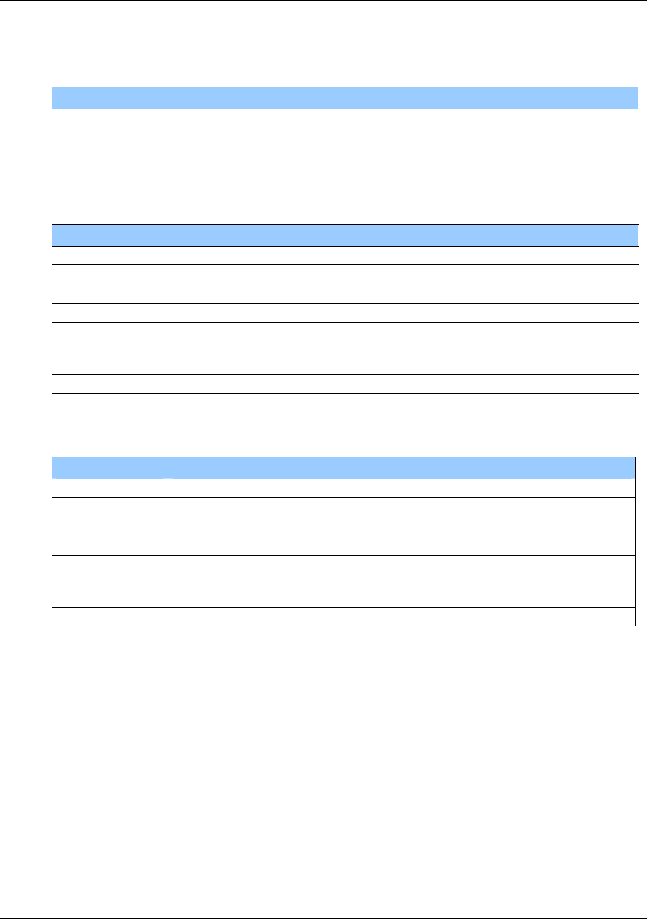
HF Multi ISO RFID Reader User Manual, Firmware V1.4 1508-USM-00-0-04
2.3.5.2.3 Option Byte
This byte contains common transfer options.
Bit Description
0, 1, 3 Bit framing. Number of bits of the last byte to transmit.
4 – 7 RFU
2.3.5.2.4 Transmit Byte
This byte contains transmit transfer options.
Bit Description
0 If set, the transmission of data is activated.
1 If set, parity generation is enabled
2 If set, parity is odd, otherwise parity is even
3 If set, CRC generation for transmission is enabled
4 If set, an 8-bit CRC is calculated, otherwise a 16-bit CRC is calculated.
5 If set, CRC is calculated according to ISO 14443 B, otherwise it is calculated
according to ISO 14443 A.
6, 7 RFU
2.3.5.2.5 Receive Byte
This byte contains receive transfer options.
Bit Description
0 If set, the receiving of data is activated.
1 If set, parity generation is enabled
2 If set, parity is odd, otherwise parity is even
3 If set, CRC generation for receiving is enabled
4 If set, an 8-bit CRC is calculated, otherwise a 16-bit CRC is calculated.
5 If set, CRC is calculated according to ISO 14443 B, otherwise it is calculated
according to ISO 14443 A.
6, 7 RFU
2.3.5.2.6 CRC Preset LSB
This byte contains the LSB of the CRC preset.
2.3.5.2.7 CRC Preset MSB
This byte contains the MSB of the CRC preset.
2.3.5.2.8 CRC generation
CRC generation is described in ISO 14443-3 Appendix B.
The CRC must be interpreted with LSB first.
August 2010 Page 93 of 144
© 2005-2010 HID Global Corporation. All rights reserved.
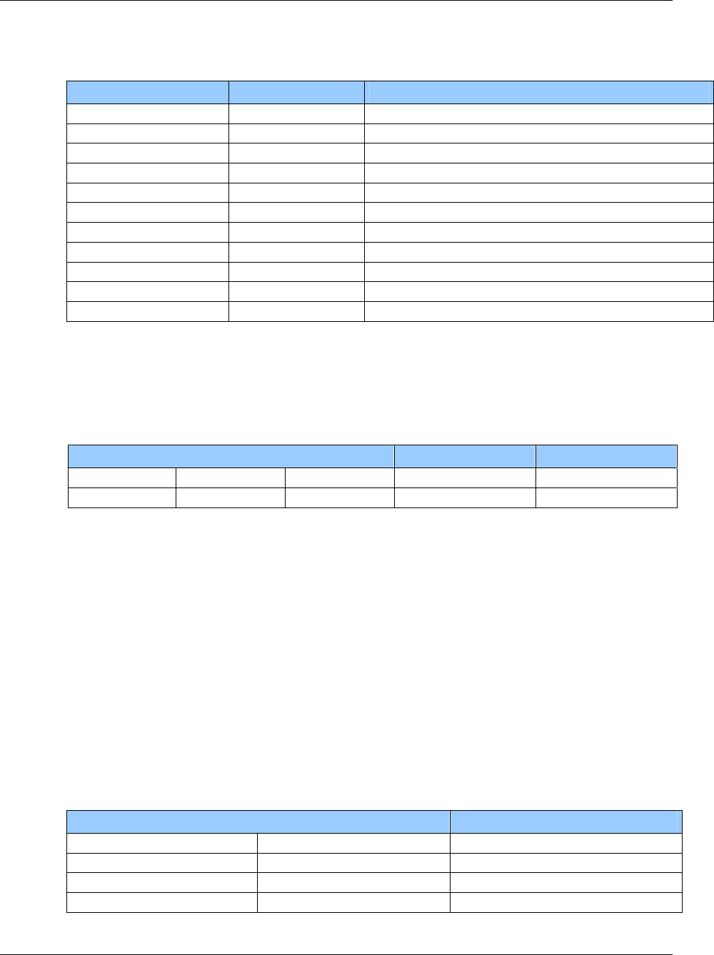
1508-USM-00-0-04 HF Multi ISO RFID Reader User Manual, Firmware V1.4
Examples for ISO 14443 A, Innovision’s Jewel tag (in Binary mode)
Sending the 'RID' command
Command Answer Description
oa OA Set tag type
t00 01 07 01 07 00 00 26 02 00 0C Send ReqA (26) and receive the answer
t00 01 07 01 00 00 00 78 00 Send first byte of RID command (78)
t00 01 00 01 00 00 00 00 00
t00 01 00 01 00 00 00 00 00
t00 01 00 01 00 00 00 00 00
t00 01 00 01 00 00 00 00 00
t00 01 00 01 00 00 00 00 00
t00 01 00 01 00 00 00 00 00
t00 01 00 01 00 00 00 D0 00
t00 01 00 01 2F FF FF 43 06 00 00 00 00 00 00 Send last byte of RID command and receive the answer
2.3.6 ‘t’ command block format & examples
For detailed coding of the Block format refer to ISO 14443-4:2001(E) section 7.1
The ‘t’ command block format is as specified in ISO 14443 part 4, and consists of some or all of
the following elements:
Prologue field Information field Epilogue field
PCB [CID] [NAD] [INF] [EDC]
1 byte 1 byte 1 byte variable 2 bytes
PCB – Protocol Control Byte [mandatory]
The PCB is used to distinguish between three different block types (Information, Receive ready
and Supervisory) as well as defining if CID is present and conveying block-related flags.
CID – Card Identifier Byte [optional]
4-bit logical card address in the range of 00h to 0Eh, 0F is RFU.
NAD – Node Address Byte [optional]
Should be compliant to NAD as defined in ISO 7816-3.
INF – Information Field [optional]
Commands and data mainly used in the application.
EDC – Error Detection Code [mandatory]
EDC is defined as a 16-bit CRC. The reader calculates the CRC automatically (refer to section
2.3.5.2.3 Option Byte, Page 93).
2.3.6.1 Block formats - Example
Description Data stream
I-Block (no CID, no NAD) Application level command 02 INF EDC
I-Block (CID=05, no NAD) Application level command 0A 05 INF EDC
R-Block (no CID, no NAD) Acknowledged A2 EDC
R-Block (CID=06, no NAD) Not acknowledged BA 06 EDC
Page 94 of 144 August 2010
© 2005-2010 HID Global Corporation. All rights reserved.
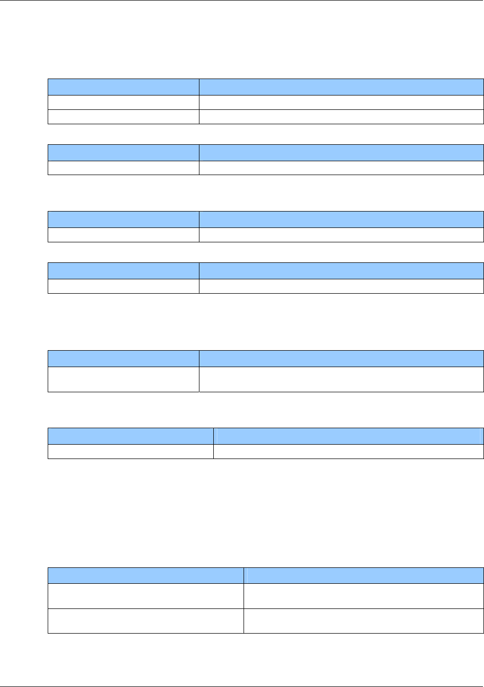
HF Multi ISO RFID Reader User Manual, Firmware V1.4 1508-USM-00-0-04
2.3.6.2 ISO-A tag manual activation sequence - Example
For single tag applications
Command Answer
t01 E3 26 02 04 00 (send REQA)
05 81635640F4 (81635640F4 denotes SN of tag)
t02 03 93 20
For multi-tag applications
Command Answer
m<CR> List of accessible tags.
To select a specific tag (after sending REQA)
Command Answer
t07 0F 93 70 81635640F4 01 88 (Select card 81635640F4)
After selecting a tag, additional parameter selection is done by the RATS sequence.
Command Answer
t02 0F E0 20 (send RATS) ATS bytes (refer to ISO 14443-4 section 5.2)
2.3.6.3 ISO-B tag manual activation sequence - Example
For single tag applications
Command Answer
t03 0C 05 00 08
(REQB, 1 time slot) 0C 50 34030F07 63223344000002
For multi-tag applications: As above, use Multi-Tag List.
To select a specific tag (after sending REQB)
Command Answer
t09 0C 1D 34030F07 00 02 01 00 01 00
2.3.6.4 Using SLE66CLX320P - Example
Since the SLE66CLX320P supports chip functionality, the transfer command must be used. To
set up a communication with the tag, the tag must be appropriately initialized. First the card must
be selected and then it is initialized sending the ATS. Afterwards the application specific
commands can be issued.
The following table describes the initialization of a SLE66CLX320P:
Command Answer
s 05 23 74 87 15 1B 04
Select card with UID 05237487151B04
t02 0F E0 50 0F 0F 77 11 E4 02 00 64 05 7D 02 03 31 80 90 00
Send ATS.
August 2010 Page 95 of 144
© 2005-2010 HID Global Corporation. All rights reserved.
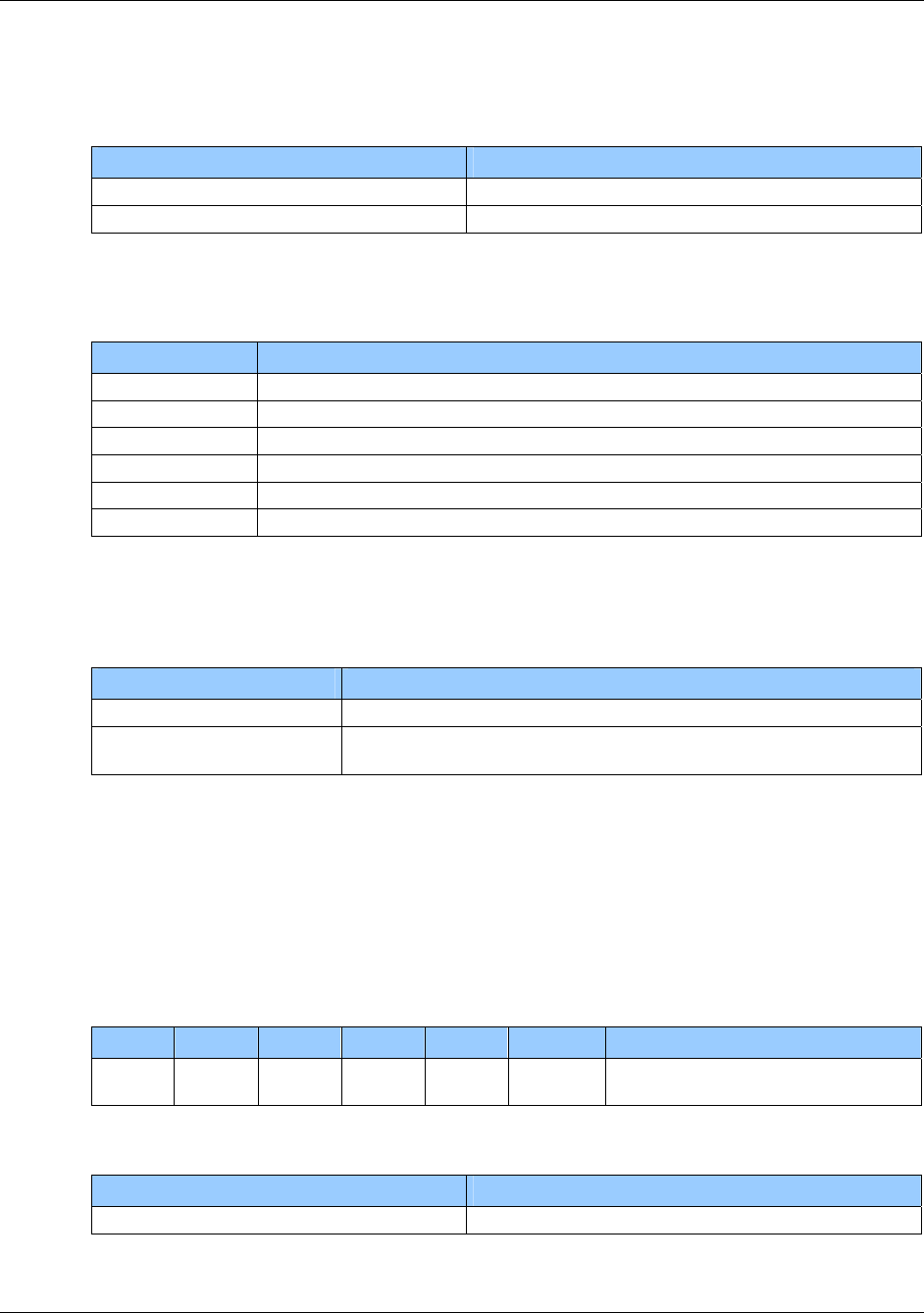
1508-USM-00-0-04 HF Multi ISO RFID Reader User Manual, Firmware V1.4
2.3.6.5 Using ASK GTML - Example
To work with the ASK GTML tag, the NoRxSOF flag has to be set to 1.
The following table lists 2 examples:
Command Answer
t03 0C 00 0B 7F APGEN without ATR
t04 0C 00 0B 3F 80 APGEN with ATR
2.3.6.6 Forcing higher baud rates - Example
To force higher baud rates use the following sequence.
Command Description
oa Select tag type
s Select tag
t02 0F E0 80 RATS
t03 0F D0 11 0A PPS
h38 Force reader to use 256 Bytes frames
h24 Force reader to use 424kBd
2.3.6.7 Using EAS with I-Code - Example
To get the EAS answer from an I-Code tag enable the EAS bits on page 3 and send the following
command with deactivated receiving CRC calculation:
Command Description
oi Preselect I-Code
t06 04 E0 00 00 00 00 00 EAS command of I-Code with Family Code 00h and Application
Identifier 00h.
2.3.6.8 Examples: How to send ISO 7816 commands?
To work with ISO 7816 commands, the tag has to be set to ISO 14443-4 mode using the high
speed select command. The data of the transfer data command is a combination of ISO 14443-4
block format and ISO 7816 command. First the ISO 14443-4 frame data has to be specified (refer
to ISO 14443-4): PCB [CID] [NAD] … PCB is mandatory and the other data bytes are optional.
After the block format data of the ISO 14443-4 the ISO 7816 command has to be specified (refer
to ISO 7816-4):
Definition of the ISO 7816 GetChallenge command:
CLA INS P1 P2 Lc Data Le
00h 84h 00h 00h Empty Empty Maximum length of expected
response
The following table lists the example with an expected response length of 8:
Command Answer
t06 0F 02 00 84 00 00 08 GetChallenge command
Page 96 of 144 August 2010
© 2005-2010 HID Global Corporation. All rights reserved.

HF Multi ISO RFID Reader User Manual, Firmware V1.4 1508-USM-00-0-04
2.3.7 ‘e’ command – SAM data frame transfer
This command sends a custom data block to a SAM. Refer to ISO/IEC 7816 for more detail.
Note: The SAM interface hardware does not support error repetition and does not check the parity
bit. Inverse convention cards are also not supported. T=0 is not supported for non-ISO standard
speeds.
There are two versions of this command. A flag bit in the option byte defines the command
version. Version 1 is the earlier one, now deprecated. Version 2 now supports ISO/IEC 7816
timeouts (BWT, CWT, WWT) both manual and automatic, TPDU interface for T=0, T=1 and a full
frame length with buffer mechanism
‘e’ command
Command Data
'e' Version 1:
Downlink length (1 byte)
Option byte (1 byte)
Time-out (1 byte)
Transmission factor byte (1 byte)
Data (n bytes)
Version 2:
Downlink length LSB (1 byte)
Option byte (1 byte)
Downlink length MSB (1 byte)
Time-out (1 byte)
Transmission factor byte (1 byte)
Return length
Data (n bytes)
Answer – Version 1
Answer Description
Data SAM response
'P' End of communication
'C' Error: CRC error
'F' Error: General failure or incorrect ATR
'N' Error: No SAM detected
Answer – Version 2
Answer Description
Error Code 00h – no error
01h – error
02h – wrong parameter
Length Data length (2bytes): optional, depends on command code used
Data SAM response
August 2010 Page 97 of 144
© 2005-2010 HID Global Corporation. All rights reserved.

1508-USM-00-0-04 HF Multi ISO RFID Reader User Manual, Firmware V1.4
2.3.7.1 Downlink length – Version 1 & Version 2 (LSB)
The Downlink length indicates only the data length. It does not include the other header bytes,
such as option and transmission factor. For Version 2 this is the LSB byte of the Downlink length.
2.3.7.2 Option byte – Version 1 (deprecated)
This byte contains the transfer options for Option 1
Table 11 - Version 1 (Option Byte)
Bit Description
0 Start communication
1 End communication
2 Cold reset
3 RFU
4 T1 length parsing
5 Warm reset
6 T=0 procedure byte 60h processing
7 0h – Version 1
Start communication
If the start communication flag is set, the command responds with an ATR from the SAM. If errors
occur, the SAM is automatically switched off and the BCC of the ATR is not checked.
End communication
Do not remove the SAM until End communication is sent.
Cold reset
If cold reset is set, the command responds with an ATR from the SAM after the cold reset of the
SAM is complete. In this case, the BCC of the ATR is not checked.
T1 length parsing
If T1 length parsing is set, the length of a T1 frame is checked so there is no additional timeout
needed to get all the characters. This only works for frames with 1 byte LRC, but not with 2 bytes
CRC.
Warm reset
If warm reset is set, the command responds with an ATR from the SAM after the warm reset of
the SAM is done. In this case, the BCC of the ATR is not checked.
T=0 procedure byte 60h processing
If set, the procedure byte 60h of the T=0 protocol is automatically processed.
Page 98 of 144 August 2010
© 2005-2010 HID Global Corporation. All rights reserved.

HF Multi ISO RFID Reader User Manual, Firmware V1.4 1508-USM-00-0-04
2.3.7.3 Option Byte Version 2
Table 12 - Version 2 (Option Byte)
Bit Description
0 - 3
Command code
0h – Transaction
1h – Activation
2h – Deactivation
3h – Warm reset
6h – Cold reset
9h – T1 S(WTX) multiplier
Fh – T=1 Transaction
all other values are RFU and should not be used
4,5
Protocol
0h – T=0 transmit
1h – T=1
2h – raw mode
3h – T=0 receive
6 Manual timeouts
7 1h – Version 2
Command code – bits 0-3
0h Transaction
This command starts a transaction with the SAM and returns the received data.
Timeout and return length depends on used protocol type and option byte.
1h Activation
This command activates the SAM and returns an ATR. If an error occurs, the SAM is
automatically deactivated.
Timeout, transmission factor and return length are not used.
2h Deactivation
This command deactivates the SAM. Do not remove the SAM until this command is sent.
Timeout, transmission factor and return length is not used.
3h Warm reset
This command makes a warm reset and returns an ATR. If an error occurs, the SAM is
automatically deactivated.
Timeout, transmission factor and return length is not used.
August 2010 Page 99 of 144
© 2005-2010 HID Global Corporation. All rights reserved.

1508-USM-00-0-04 HF Multi ISO RFID Reader User Manual, Firmware V1.4
Fh T=1 APDU implementation
This command performs all of the wrapping for APDU message structures, using the T=1 block
transmission protocol as detailed in ISO 7816-3. The ‘data’ field of the ‘e’ command comprises
just the APDU Header [CLA, INS, P1, P2] and the Body [Lc, Data, Le] and the response APDU
comprises the Body [Data] and Trailer [SW1, SW2] – see ISO 7816-4.
Protocol – bits 4, 5 (The protocol flags are only used for the transaction command.)
0h T=0
This protocol type supports a full TPDU interface.
Timeout is used as WWI value if the manual timeout flag is set, otherwise the timeout is
automatically taken from the ATR.
Return length is used.
1h T=1
For T=1 protocol include the frame in the data field.
Timeouts are used as BWI/CWI values if the manual timeout flag is set, otherwise the
timeouts automatically are taken from the ATR.
Do not use return length.
2h RAW
This protocol type uses a fixed timeout of WT = 9600etu and is only supported in the
default speed (F/D=1). [NB If a zero return length is specified, the reader waits 9600etu
after the last received character before returning the reply. Therefore, it is recommended to
specify the return length (if known) in order to avoid any delay]
Send the PPS command with this protocol type.
Timeout is not used. Return length is used.
3h RFU
Do not use the RFU value.
Manual timeouts – bit 6
If set, the value of the timeout byte is used for T=0 and T=1 protocol; otherwise the timeouts are
automatically taken from the ATR.
2.3.7.4 Time-out
Version 1
The time-out byte is used as the communication time-out between two characters. One time slice
is approximately 9.6ms. If setting the timeout value to zero, use a maximum timeout of 3.6
seconds. Use the TMR timeout until the first character is received.
Version 2
The timeout byte represents the WWI value for T=0 protocol and BWI/CWI values for the T=1
protocol. BWI and CWI are encoded in the same way as in ATR. (See ISO/IEC 7816-3)
These values are only used if the manual timeout flag is set – see Table 12 - Version 2 (Option
Byte).
Page 100 of 144 August 2010
© 2005-2010 HID Global Corporation. All rights reserved.

HF Multi ISO RFID Reader User Manual, Firmware V1.4 1508-USM-00-0-04
2.3.7.5 Transmission Factor – Versions 1 & 2
This byte contains the clock rate conversion and baud rate adjustment according to ISO/IEC
7816-3. The default value on start-up is 11h (F/D = 1)
The following pairs of F (clock rate conversion factor) and D (baud rate adjustment factor) are
supported.
F D Description
128 8, 16, 32
(Di = 4,5,6)
Non ISO standard transmission factor
[ T=0 not supported for these F|D values ] (Fi=8)
372
(Fi=0,1)
0, 1, 2, 4, 8, 12
(Di = 0,1,2,3,4,8)
ISO standard transmission factors
512 32, 64 ISO standard transmission factors
(Fi=9) (Di = 6,7)
Clock
A clock of 3.39MHz is used.
Transmission Protocol
The supported transmission protocol types are T=0 and T=1. For these protocol types, the ATR is
checked.
This command does not process the block frame of the transmission protocol T=1; all bytes are
passed through.
The user has to specify the block frame by itself.
DESfire SAM
The non-ISO standard transmission factors supporting baud rates up to 847500 Baud.
Hardware
The SAM interface does not support error repetition and does not check the parity bit.
August 2010 Page 101 of 144
© 2005-2010 HID Global Corporation. All rights reserved.

1508-USM-00-0-04 HF Multi ISO RFID Reader User Manual, Firmware V1.4
2.3.8 ‘e’ command block
Examples – Version 1 & 2
Command Description
e:00 01 10 11 (Version 1) Start communication
Answer: ATR
e:00 81 00 10 11 00 (Version 2) Start communication (T=0)
e:00 91 00 10 11 00 (Version 2) Start communication (T=1)
Answer: 00 len-ATR ATR
e:04 00 10 11 FF 11 86 68 (V1) PPS
Answer: FF 11 86 68 (if tag agrees with proposal)
e:04 A0 00 00 11 04 FF 11 86 68 (V2) PPS
Answer: 00 00 04 FF 11 86 68 (if tag agrees with proposal)
e:00 20 10 11 (V1) Warm reset
Answer: ATR
e: 00 83 00 10 11 00 (V2) Warm reset (T=0)
e: 00 93 00 10 11 00 Warm reset (T=1)
Answer: 00 len-ATR ATR
e:00 02 00 00 (V1) End communication
Answer: P
e:00 82 00 10 00 00 (V2) End communication (T=0)
e:00 92 00 10 00 00 End communication (T=1)
Answer: 00h
The following commands are taken from the NXP DESFire8 SAM-X specification document
e:05 00 00 10 11 00 00 84 00 00 08 GetChallenge for T=0
e:09 00 00 10 11 00 00 00 05 80 84 00 00 08 09 GetChallenge for T=1. This now includes the T=1 frame
Answer: 00 len-reply reply (varies)
e:08 00 10 11 00 5A 00 00 03 (3 bytes DF-AID) SelectApplication for T=0
e:0C 00 10 11 00 00 08 80 5A 00 00 03 SelectApplication for T=1 This now includes the T=1 frame
(3 bytes DF-AID) EDC
Answer: (2 bytes) – see DESFire SAM spec
e:08 80 00 10 11 00 00 5A 00 00 03 (3 bytes DF-AID) SelectApplication for T=0
e:0C 90 00 10 11 00 00 00 08 80 5A 00 00 03 SelectApplication for T=1 This now includes the T=1 frame
(3 bytes DF-AID) EDC
Answer: 00 02 reply – see DESFire SAM spec
e:08 9F 00 10 11 00 80 5A 00 00 03 (3 bytes DF_AID) DESFire SAM_SelectApplication using T=1 APDU. Notice
there is no block format or EDC, just the ‘INF’ APDU data
Answer: Data SW1 SW2 [ - 90 00 for ‘ack’]
Page 102 of 144 August 2010
© 2005-2010 HID Global Corporation. All rights reserved.

HF Multi ISO RFID Reader User Manual, Firmware V1.4 1508-USM-00-0-04
3 EMVCO Commands
For EMVCO processing details, reference the EMV Contactless Communication Protocol Specification.
Command Description Response Description
1.Card Number Single PICC found
2.’C’
Collision detected
‘_p’ ( Poll Command)
No Data
This command enters EMV
mode and starts polling. The
reader scans for the field for
ISO 14443 A and B cards
until card is found.
3.’N’
Timeout error
1. 0x01 Polling for PICC
2. 0x02
Activating PICC
3. 0x03
Transaction mode.
‘_s’ ( Status Command)
No Data
Gets the reader state in
EMVCO mode.
4. 0x04 Removal procedure of PICC
1. Card response
2. ‘N’
Timeout error
3. ‘P’
Protocol error
4.’F’ Transmission error(CRC/BCC)
‘_tt’ (Transfer command
)
Data – APDU(n Bytes)
This command starts a half
duplex block transmission
sequence with an already
activated tag.
5. ‘O’ FIFO Overflow error
‘_r’ ( Remove Command)
No Data
This command starts the
removal procedure of PICC. ‘N’ Timeout error after the removal
is completed.
‘_q’ ( Quit Command) This command quits the
reader form the EMV mode ‘Q’
Quit from EMV mode
No data
Unknown command ‘?’
August 2010 Page 103 of 144
© 2005-2010 HID Global Corporation. All rights reserved.

1508-USM-00-0-04 HF Multi ISO RFID Reader User Manual, Firmware V1.4
4 Frequently Asked Questions
4.1 Getting Started
Q. How do I get started?
A To test and interface the MultiISO Compact or Comfort Module, you do not need a
sophisticated µP development system. All you need is a PC, a connection cable and a
suitable power supply for the reader. If you are using Microsoft Windows
(95/98/NT/XP/...), take the following steps:
Make sure that your reader has an RS232 interface
Start HyperTerminal
Create a new connection (FILE/NEW CONNECTION)
Enter a name for the connection (i.e. ‘MIFARE ’)
Select connect COM2 (COM1) direct connection
Connection setup 9600,8,n,1,no handshake
Connect your reader to COM2 (COM1) of the PC and apply appropriate supply
voltage. The reader transmits a string (“MultiISO 1.2”) to the PC.
This string denotes the firmware provided with your reader module
Put a tag to your reader. Serial numbers should be displayed properly
Enter commands (see
Page 104 of 144 August 2010
© 2005-2010 HID Global Corporation. All rights reserved.

HF Multi ISO RFID Reader User Manual, Firmware V1.4 1508-USM-00-0-04
Command Set, page 37) with the keyboard. They should be transmitted to the reader
and the reader should reply
If using an operating system different from Microsoft Windows, you may use any other
terminal program that is capable of receiving/transmitting data through the serial port of
your PC.
4.2 Personalizing Multi ISO Reader
Q. How do I personalize the Multi ISO Reader?
A In ASCII protocol applications, no personalization is necessary.
In applications that are using the binary protocol mode, personalization is required. Use the
Utility program to set up your reader correctly. Contact support: eusupport@hidglobal.com
to acquire the utility. Minimum requirements are WIN98SE, WIN 2000, WIN XP and a free
COM port on the PC.
August 2010 Page 105 of 144
© 2005-2010 HID Global Corporation. All rights reserved.

1508-USM-00-0-04 HF Multi ISO RFID Reader User Manual, Firmware V1.4
4.3 MIFARE Card Type
Q. What type of MIFARE card should I use?
A The MIFARE standard is designed for multi-application environments. It contains 16
sectors each with 2 individual keys, access conditions, and 3 data or value blocks. Some
applications use the 1 Kbytes of the MIFARE Standard Card Memory only as storage
area.
MIFARE Ultra light has no crypto unit on chip. It only supports 16 blocks.
MIFARE Standard 4k cards have the same features as MIFARE Standard cards but
increased memory capacity.
4.4 MIFARE
Q. How safe is MIFARE Standard for cashless payment?
A Security is always a feature of the overall system, not of the components. It requires
careful design.
A properly designed system will require ALL barriers to be hacked in order to be broken.
For good design start identifying possible attacks and then create barriers to block them.
MIFARE was specifically designed for cashless payment applications. The MIFARE
concept provides the following security barriers:
Anti-collision/-selection
Atomic value transaction
Ciphered communication
Storage of values and data protected by mutual authentication
Weak field keys that allow decrement only
Stored keys in the reader that are not readable
Keys in the card that are not readable
A brute force attack based on trying many different keys is limited by the transaction
time (several ms) of the card and would last virtually forever.
Page 106 of 144 August 2010
© 2005-2010 HID Global Corporation. All rights reserved.

HF Multi ISO RFID Reader User Manual, Firmware V1.4 1508-USM-00-0-04
The Application can and should provide more barriers:
Sector access conditions. It is possible to assign access conditions in a way that only
decrementing of values is allowed with the keys used in the field. So even a
manipulated field station cannot be used to increment the value on the cards. As a
general rule, key A is used as a field key, allowing only to read and decrement values,
and key B is used to format the card or increment values.
Diversified keys. To make life even harder for attackers, keys can be modified using
the serial number and memory content of the card. So each card uses different keys
and a listening attack on the reader interface would be hopeless.
Limiting cash volume stored on a card
Do not use the transport keys (keys programmed at the time of delivery) for ticketing
applications!
Ciphered and scrambled data storage
Sabotage alarm
Even higher security with contact less controller cards like DESFire, MIFARE ProX,
MIFARE Smart MX etc.
Q. How do I use a MIFARE card?
A This example demonstrates the detection of a card in the antenna field with continuous
read and the reading of a page.
Command Answer
C Activate continuous read mode
B2197B58
a card responds with its serial number
. S
abort continuous read mode
S B2197B58
select card
l01AAFFFFFFFFFFFF L
login into sector 1 with key FFFFFFFFFFFFh key type A
rb04 00112233445566778899AABBCCDDEEFF
read block 04
c Activate continuous read mode to detect a new card
August 2010 Page 107 of 144
© 2005-2010 HID Global Corporation. All rights reserved.

1508-USM-00-0-04 HF Multi ISO RFID Reader User Manual, Firmware V1.4
4.5 Using NFC
Q. How do I use NFC?
A The example shows how to communicate with NFC using the NFC demo-board PN531.
The reader is the initiator. The NFC has to be configured as passive target using MIFARE
106kbps (other NFC modes are not supported).
As first step place the reader on top of the NFC demo-board antenna in 3 cm distance.
Then load the "passive_target_106.cmd" file from the "Scripts\Tama\P2P" subfolder into the
SCRTester application. Run the code.
Now it is possible to get a serial number from the NFC.
Command Answer
S 08123456
Page 108 of 144 August 2010
© 2005-2010 HID Global Corporation. All rights reserved.
HF Multi ISO RFID Reader User Manual, Firmware V1.4 1508-USM-00-0-04
5 Supported Tags
5.1 MIFARE Transponder Family
The MIFARE transponder family consists of various 13.56 MHz transponder ICs, all compliant to
the ISO 14443. Infineon My-D tags that support the MIFARE command set are also included here.
5.1.1 MIFARE Standard
The MIFARE Standard card consists of 16 sectors. A sector includes four blocks of 16 bytes each.
MIFARE Standard Sector 2
Sector 0 (Block: 0...3) Block 8: Data or value (16 bytes)
Sector 1 (Block: 4...7) Block 9: Data or value (16 bytes)
Sector 2 (Block 8...11) Block 10: Data or value (16 bytes)
... Block 11: Access Conditions (4 bytes),
Key A, Key B (16 bytes)
Sector 15 (Block 60...63)
5.1.1.1 Sector 0 / Block 0
Block 0 is read only.
Serial Number (4 bytes) Check byte (1 byte) Manufacturer data (11 bytes)
5.1.1.2 Blocks 3, 7, 11, 15 …
Transport keys are set on delivery:
Key A (6 bytes) Access Conditions (4 bytes) Key B (6 bytes)
Key A
A0 A1 A2 A3 A4 A5 (Infineon) or FF FF FF FF FF FF (new NXP cards)
Key B
B0 B1 B2 B3 B4 B5 (Infineon) or FF FF FF FF FF FF (new NXP cards)
Access Conditions
FF 07 80 xx (key A is used to read or write; key A itself is not readable; key B is data only). For
further information refer to the MIFARE card manual.
Remarks
Enabled keys are always read as 00 00 00 00 00 00
Using key B as a data area will cause a security gap, due to the fact that it is necessary to rewrite
key A and the access conditions at each write process. It is not recommended to use key B as a
data storage area.
August 2010 Page 109 of 144
© 2005-2010 HID Global Corporation. All rights reserved.
1508-USM-00-0-04 HF Multi ISO RFID Reader User Manual, Firmware V1.4
All MIFARE cards use the following state diagram.
Power Off
Idle
Ready
Active
Authenticated
Halt
Authenticate
Select
REQA
Reset
Wake Up Halt
Log In Select
read/write/... Tag interfacing
commands
Reader Instruction Set
ISO 14443 Commands
Anticollision Loop
Figure 10 - State Diagram
Page 110 of 144 August 2010
© 2005-2010 HID Global Corporation. All rights reserved.

HF Multi ISO RFID Reader User Manual, Firmware V1.4 1508-USM-00-0-04
5.1.2 MIFARE Ultra-light
MIFARE Ultra-light cards have no encryption included. They only support plain text data
transmission.
MIFARE Ultra-light only supports 4 bytes per sector, but the command set uses 16 bytes per sector.
Only the 4 least significant bytes are valid when using MIFARE Ultra-light.
Ensure that the other bytes match with the tag content when using the write command; otherwise
the read back will fail.
5.1.3 MIFARE 4k
MIFARE 4k cards have an increased memory. Beginning from sector 32 (20h), sectors have 16
blocks. Due to compatibility reasons, the sector indices have changed according to the following
table. The login sector has to be used to access the corresponding sector on the card.
Sector Block Login sector
00h 00h – 03h 00h
01h 04h – 07h 01h
… … …
1Fh 7Ch – 7Fh 1Fh
20h 80h – 8Fh 20h
21h 90h – 9Fh 24h
22h A0h – AFh 28h
23h B0h – BFh 2Ch
24h C0h – CFh 30h
25h D0h – DFh 34h
26h E0h – EFh 38h
27h F0h – FFh 3Ch
5.1.4 MIFARE Prox
MIFARE Prox tags have an operating system onboard. Data organization depends on the operating
system installed on the card. These cards can include additional functionalities such as DES or a
proprietary encipher algorithm.
Before accessing the operating system, the card must be selected. Customized commands are
issued using the transfer command.
August 2010 Page 111 of 144
© 2005-2010 HID Global Corporation. All rights reserved.

1508-USM-00-0-04 HF Multi ISO RFID Reader User Manual, Firmware V1.4
5.1.5 MIFARE DESFire
This tag supports additional security algorithms (DES, Triple-DES, MAC) for security sensitive
applications.
5.1.5.1 Memory organization
The memory of a DESFire card can be personalized to specific requirements. The card can be seen
as data storage device like a hard disk in a PC. The memory is divided into a maximum of 28
different applications (directories) with 16 files each. An application has up to 14 keys. Depending
on keys and access conditions a file can be accessed in four different ways. Plain data is never
secured. Data is secured using a MAC, single DES or triple DES enciphers.
The following figure describes the memory organization of a DESFire card.
File
ID 2
Application 1
File
ID 1 ... File
ID n
File
ID 2
Application 2
File
ID 1 ... File
ID n
File
ID 2
Application n
File
ID 1 ... File
ID n
...
DESFire card (Application 0)
Figure 11 - DESFire Memory
Page 112 of 144 August 2010
© 2005-2010 HID Global Corporation. All rights reserved.
HF Multi ISO RFID Reader User Manual, Firmware V1.4 1508-USM-00-0-04
Activate DESFire card
Select Application
Login to Application
Select File with ID
Change File
Commit / Abort Transaction
Figure 12 - DESFire State Diagram
August 2010 Page 113 of 144
© 2005-2010 HID Global Corporation. All rights reserved.

1508-USM-00-0-04 HF Multi ISO RFID Reader User Manual, Firmware V1.4
5.1.5.2 Activate PICC
Before accessing a DESFire card, the card must be selected. A DESFire card has a 7 byte UID.
After activation, the card is powered up and ready to accept a DESFire command. Application 0 is
selected automatically.
5.1.5.3 Select application
To jump into another application, the application has to be selected. An application can be seen as
a directory, which contains up to 16 files. The size of the application depends on the stored files.
5.1.5.4 Login to application
Specific access rights can be set for each application. Login to an application allows changing the
organization of the application. Login to a file opens a secured file for access. A file can be
accessed in four different ways: without any security or secured with MAC, single DES or triple
DES.
5.1.5.5 Select file
Before accessing a file, the file must be selected
5.1.5.6 Change file
A selected file can be changed according its access rights. If a file is secured, a login is required
before changes can be made.
5.1.5.7 Commit / Abort transaction
Value files, backup files, linear record files and cyclic record files only adapt their values after the
commit transaction command is given. Several files can be changed within an application at the
same time. The abort transactions command annuls all changes within an application. Power loss
will cancel all modifications too.
For more details about application settings and access rights refer to [2].
Page 114 of 144 August 2010
© 2005-2010 HID Global Corporation. All rights reserved.
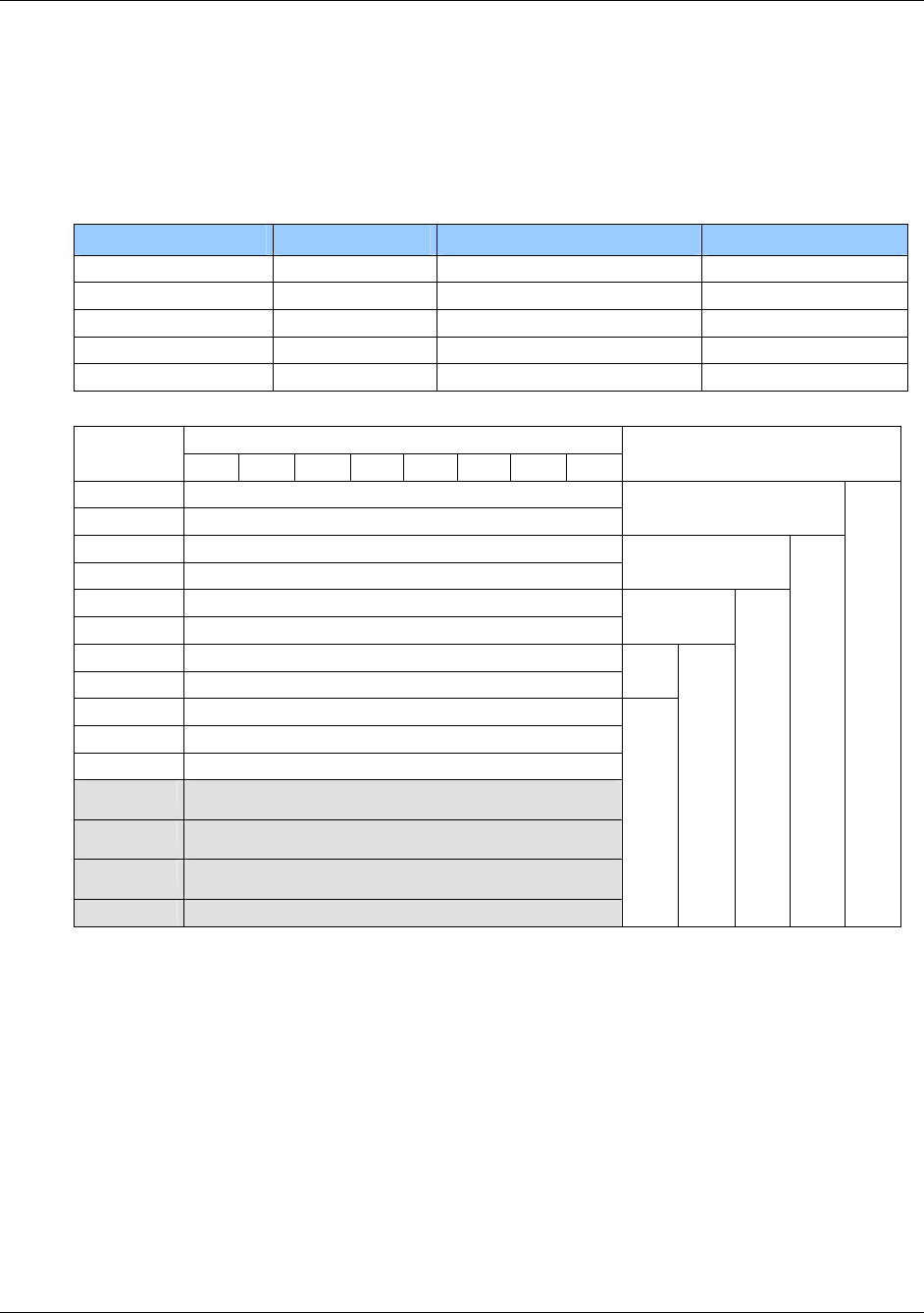
HF Multi ISO RFID Reader User Manual, Firmware V1.4 1508-USM-00-0-04
5.1.6 my-d™ IC (SLE 55Rxx)
my-d™ ICs are specific ICs from Infineon. These labels show a different memory organization. Two
different modes of tags are supported: plain and secure mode.
Memory Size of SLE Rxx-family
Type User Memory Administration Memory Number of pages
SLE 55R01 128 Bytes 32 Bytes 16
SLE 55R02 256 Bytes 64 Bytes 32
SLE 55R04 616 Bytes 154 Bytes 77
SLE 55R08 1024 Bytes 256 Bytes 128
SLE 55R16 2048 Bytes 512 Bytes 256
Byte number within a page
Address 0 1 2 3 4 5 6 7
FFh User data
… …
7Fh User data
… …
4Ch User data
… …
1Fh User data
… …
0Fh User data
… …
04h User data
03h
02h
01h
SLE 55R01
SLE 55R02
SLE 55R04
SLE 55R08
SLE 55R16
00h Serial number (UID)
August 2010 Page 115 of 144
© 2005-2010 HID Global Corporation. All rights reserved.
1508-USM-00-0-04 HF Multi ISO RFID Reader User Manual, Firmware V1.4
5.2 ISO 14443 Type B
ISO 14443 type B cards are supported.
5.2.1 SR176
The SR176 label contains only 30 bytes of data organized in two bytes per page.
5.2.1.1 Memory organization
Block address Byte 1 Byte 0
0Fh Lock byte RFU Chip ID
0Eh User data
… …
04h User data
03h Serial number
02h Serial number
01h Serial number
00h Serial number
5.2.1.2 Serial number UID
The UID is stored in the first 4 pages. Page 00h contains the LSB of the UID.
Page 03h Page 02h Page 01h Page 00h
Byte 1h Byte 0 Byte 1 Byte 0 Byte 1 Byte 0 Byte 1 Byte 0
5.2.1.3 Lock byte
The lock byte defines the write access condition of a pair of pages. Each bit can only be set once.
This procedure is irreversible. This byte is implemented as an OTP.
Bit 7 Bit 6 Bit 5 Bit 4 Bit 3 Bit 2 Bit 1 Bit 0
Page 0Eh Page 0Fh
Page 0Ch Page 0Dh
Page 0Ah Page 0Bh
Page 08h Page 09h
Page 06h Page 07h
Page 04h Page 05h
Page 02h Page 03h
Page 00h Page 01h
5.2.1.4 Chip ID
The Chip ID is defined in the low nibble of page 0Fh. It is manufacturer set and is used internally to
select and separate single tags.
Page 116 of 144 August 2010
© 2005-2010 HID Global Corporation. All rights reserved.
HF Multi ISO RFID Reader User Manual, Firmware V1.4 1508-USM-00-0-04
5.2.2 SRIX4K
The SRIX4K label contains 512 bytes of data organized into four-byte pages.
5.2.2.1 Memory organization
Block address Byte 3 Byte 2 Byte 1 Byte 0
FFh OTP Lock Reg ST Reserved ST Reserved Fixed Chip ID
7Fh User data
… …
07h User data
06h 32 bits binary counter
05h 32 bits binary counter
04h 32 bits Boolean Area
03h 32 bits Boolean Area
02h 32 bits Boolean Area
01h 32 bits Boolean Area
00h 32 bits Boolean Area
5.2.2.2 Lock block
Locking of blocks is not supported with this tag.
5.3 ISO 15693
The reader can communicate with ISO15693 tags. An anti-collision is needed if multiple instances
of tags are in the same antenna field. The reader detects each type of ISO15693 labels and
handles them individually
5.3.1 Coding of UID
The UID of a tag is defined in ISO/IEC 15693-3. All tags compliant to ISO15693 support the
specified format. The UID is factory programmed and cannot be changed. The UID is needed for
the anti-collision sequence to separate several tags in the same antenna field.
Byte
7 6 4 3 2 5 1 0
E0h MFR
Code Serial number
The MFR Code is listed in ISO/IEC 7816-6:1996/Amd.1: 2000(E). Following manufacturers are
tested with our reader.
MFR-Code Company
02h ST Microelectronics
04h NXP Semiconductors
05h Infineon Technologies AG
07h Texas Instrument
16h EM Microelectronic-Marin SA
August 2010 Page 117 of 144
© 2005-2010 HID Global Corporation. All rights reserved.
1508-USM-00-0-04 HF Multi ISO RFID Reader User Manual, Firmware V1.4
5.3.2 Memory organization
An ISO15693 tag is separated into two blocks. An administrative block contains the UID, AFI,
DSFID and the lock page state. The user block is free for custom use. The chip manufacturer
defines the amount of bytes and number of pages of each tag. As default four bytes are used for
several tags.
Byte
Page
address 0 1 2 3
3Fh User data
… …
00h User data
Administrative block
5.3.3 my-d™ IC (SRF55VxxP)
my-d™ ICs are specific ICs from Infineon. These labels show a different memory organization. Two
different modes of tags are supported: plain and secure mode.
Two different cards with 320 bytes or 1k bytes EEPROM memory are available. The EEPROM
memory is divided into pages.
Each tag is split into two parts: The administrative blocks (00h, 01h, 02h) and the user area.
Administrative pages are read only and cannot be changed. User data is free for use. Additionally
user data pages can be locked. This procedure is irreversible.
The EEPROM of SRF55V10P is organized in 128 pages addressed 00h to 7Fh. The EEPROM of
SRF55V02P consists of 32 pages addressed 00h to 1Fh.
Byte number within a page
Address 0 1 2 3 4 5 6 7
7Fh User data
… …
1Fh User data
… …
03h User data
02h
01h
SRF55V02P
SRF55V10P
00h Serial number (UID)
5.3.3.1 UID
The UID of SRF55Vxx labels starts with 60h or E0h.
Page 118 of 144 August 2010
© 2005-2010 HID Global Corporation. All rights reserved.

HF Multi ISO RFID Reader User Manual, Firmware V1.4 1508-USM-00-0-04
5.3.3.2 Security Bit
Bit 45 of the UID defines the secure mode of the SRF55Vxx. If set, the tag supports security
algorithm.
Bit 45 Description
1 Tag supports crypto security mechanism
0 Chip supports plain mode only
5.3.4 EM 4135
The EM4135 is an ISO15693 compliant label of EM Microelectronic-Marin SA. It has eight bytes per
page as the same as the my-d™ label. It only supports 36 pages. The administrative area holds the
information of the access condition and the UID.
Page
Address 0 1 3 4 2 5 6 7
23h User data
… …
00h User data
Administrative area
August 2010 Page 119 of 144
© 2005-2010 HID Global Corporation. All rights reserved.
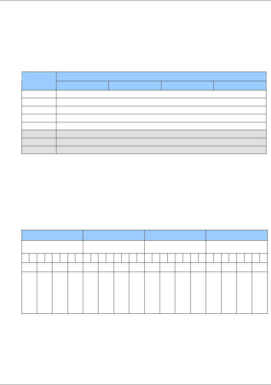
1508-USM-00-0-04 HF Multi ISO RFID Reader User Manual, Firmware V1.4
5.4 ICODE
ICODE® IC data is stored in a non-volatile EEPROM. Its capacity is 512 bits organized in 16 blocks
consisting 4 bytes each (1 block = 32 bits). First 3 blocks contain administrative data.
5.4.1 Memory organization
Byte
Page
address 0 1 2 3
0Fh User data
… …
05h User data
04h Family code identifier / User data
03h Special function (EAS) / User data
02h Write access condition
01h Serial number
00h Serial number
5.4.2 Serial number
The serial number of a label is defined at the manufacturer process. It is stored on page 00h and
page 01h. LSB is stored first.
5.4.3 Write access condition
Page 02h contains the write access condition for each page. Each page can be set to read only
(bits are set to 0). This procedure is irreversible. Locking page 2 no further changed of the access
condition can be done. Always two bits must be change at the same time. This register is
implemented as OTP.
Byte 0 Byte 1 Byte 2 Byte 3
MSB LSB MSB
LSB MSB
LSB MSB
LSB
1 1 1 1 0 0 0 0 1 1 1 1 1 1 1 1 1 1 1 1 1 1 1 1 1 1 1 1 1 1 1 1
3 2 1 0 7 6 5 4 B A 9 8 F E D C
Special function
Write access
Serial number
Serial number
User data
…
…
…
…
…
User data
…
…
…
…
…
Page 120 of 144 August 2010
© 2005-2010 HID Global Corporation. All rights reserved.

HF Multi ISO RFID Reader User Manual, Firmware V1.4 1508-USM-00-0-04
5.4.4 Special function (EAS,) AFI
Special Functions (EAS) and Family Code/Application Identifier are additional features. For more
information refer to the ICODE® manual.
5.4.5 User data
All other blocks are free for use and can be changed according the state of the write access
conditions.
5.5 ICODE EPC
ICODE EPC labels data is stored in a OTP memory. Its capacity is 136 bits organized in 17 blocks
consisting of 1 bytes each. All MSB of the different fields (EPC, CRC16, Destroy Code) are located
at the lowest block address.
5.5.1 Memory organization
Page address Byte
14h – 16h Destroy Code
12h – 13h CRC 16
00h – 11h EPC
5.5.2 Serial number
The serial number of a label is defined within the EPC blocks.
5.5.3 Read Block
It is not possible to read a block with the read block 'rb' command.
5.5.4 Write Block
It is possible to write the EPC data (12 bytes) with the write block 'wb' command using block
address 00h.
5.6 ICODE UID
The memory has a capacity of 192 bits and is organized in 24 blocks, consisting of 1 byte each. All
MSB of the different fields (UD, UD CRC, CRC16, Destroy Code) are located at the lowest block
address.
5.6.1 Memory organization
Page address Access Condition Description
21h – 23h OTP Destroy Code
19h - 20h OTP CRC16
14h – 18h RO UID
12h – 13h R/W UD CRC16
00h – 11h R/W User data (UD)
August 2010 Page 121 of 144
© 2005-2010 HID Global Corporation. All rights reserved.

1508-USM-00-0-04 HF Multi ISO RFID Reader User Manual, Firmware V1.4
5.6.2 Read Block
It is possible to read the user data (12 bytes) with the read block 'rb' command using block address
00h.
5.6.3 Write Block
It is possible to write the UD data (12 bytes) with the write block 'wb' command using block address
00h.
Additionally it is possible to write the destroy code (3 bytes) with the write block 'wb' command using
block address 01h.
Page 122 of 144 August 2010
© 2005-2010 HID Global Corporation. All rights reserved.

HF Multi ISO RFID Reader User Manual, Firmware V1.4 1508-USM-00-0-04
Appendix A - References
[1] ISO/IEC 14443 Part 1-4, Identification Cards – Contact less integrated circuit(s) cards – Proximity
cards
[2] DESFire Documentation, NXP (formerly Philips), http://www.nxp.com
[3] Data Encryption Standard (DES), FIPS PUB 46-3,
Reaffirmed 1995 October 25
[4] HID Antenna Design Guide
[5] NXP (formerly Philips); Application Note, MIFARE & I-Code, Micore Reader IC family Directly
Matched Antenna Design
[6] NXP (formerly Philips) Data sheet MC073933 for CL RC632 Reader IC
[7] PayPass - ISO 14443 Implementation Specification
PayPass - Terminal
August 2010 Page 123 of 144
© 2005-2010 HID Global Corporation. All rights reserved.
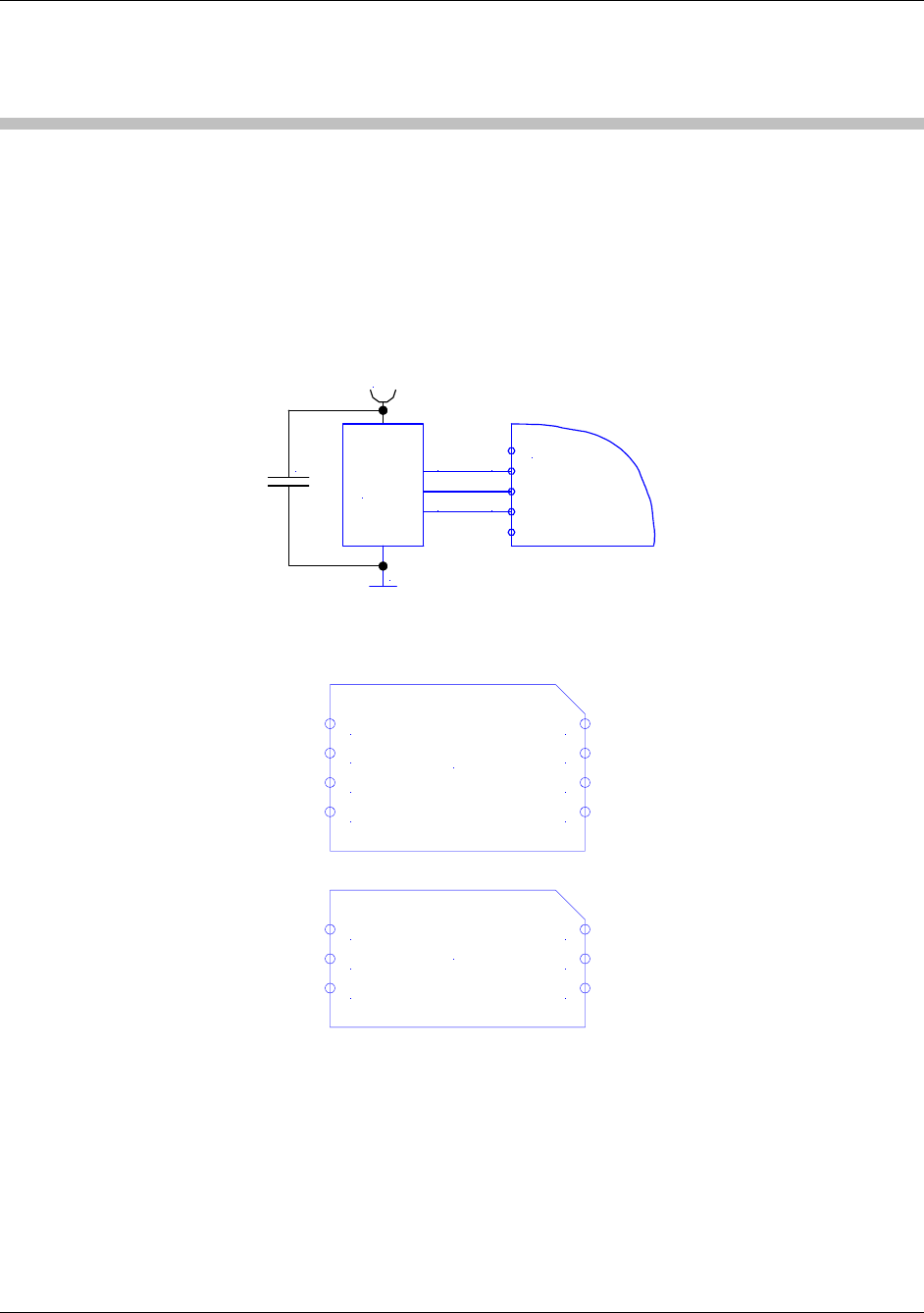
1508-USM-00-0-04 HF Multi ISO RFID Reader User Manual, Firmware V1.4
Appendix B - SAM Socket Details
[These details appear in the Hardware Section (1), but are repeated here for convenience]
Note: The power supply to the SAM must be turned off during the entire SAM insertion/withdrawal
period; otherwise damage to the SAM may occur
Communication with the SAM is performed using the ‘e’ command – see ‘e’ command – SAM data
frame transfer, page 97.
When using a SAM with the HID HF MultiISO OEM board, it is recommended that a 100nF
decoupling capacitor be fitted between Vcc and GND close to the SAM socket to ensure proper
operation. The complete circuit diagram is shown below.
7OEM Board
8
9
SAM
Module
Vcc
GND
CLK
I/O
RST
100nF
PIN-out for an 8 Pin SAM Socket and for a 6 Pin SAM Socket
8 NC
7 I/O
6 NC
5 GND VCC 4
RST 3
CLK 2
NC 1
8 PIN
SAM
6 I/O
5 NC
4 GND VCC 3
RST 2
CLK 1
6 PIN
SAM
Page 124 of 144 August 2010
© 2005-2010 HID Global Corporation. All rights reserved.
HF Multi ISO RFID Reader User Manual, Firmware V1.4 1508-USM-00-0-04
Appendix C - Timings
t
CMD t
EXEC t
RES
PC: Request
Reader: Response
Table 13 - Timings
Command tEXEC [ms] Comments
Common commands
Cont. read (locked tag) 2.8 – 22.6 + Reset Off and Recovery Time
Cont. read (worst case) 54 + 3x Reset Off and Recovery Time
DES en/decryption 9.6 – 9.7
TDES en/decryption 28.7 – 28.8
High-speed select 'h08'
(locked tag) 8.9 – 14.4 + Reset Off and Recovery Time + SFGT
High-speed select 'h08'
(no tag) 15 + 3x Reset Off and Recovery Time
High-speed select 'h08'
(worst case) 14.7 + 3x Reset Off and Recovery Time + SFGT
Multi-select (locked tag) 5.8 – 11.4 + Reset Off and Recovery Time
Multi-select (no tag) 67 + Reset Off and Recovery Time
Multi-select (worst case) 67 + Reset Off and Recovery Time
Antenna on 0.2 + Reset Recovery Time
Antenna off 0.2
Port read 0.1
Port write 0.1
Read block 1.8 – 2.2
Write block 8.2 – 11
Reset 13.2
Select (locked tag) 5.4 – 22.8 + Reset Off and Recovery Time
Select (no tag) 38 + 3x Reset Off and Recovery Time
Select (worst case) 55 + 3x Reset Off and Recovery Time
August 2010 Page 125 of 144
© 2005-2010 HID Global Corporation. All rights reserved.

1508-USM-00-0-04 HF Multi ISO RFID Reader User Manual, Firmware V1.4
Command tEXEC [ms] Comments
ISO 14443 Type A only commands
Increment value block 18.4
Decrement value block 18.4
Copy value block 18.5
Read value block 2.3
Write value block 7.9 - 10.5
MIFARE Login 4.9
Power conditions
Power on 79 Does not include rise time of power supply
Enable on 85
Used was the default Command Guard Time (20h = 1.2ms).
All timing data is advisory application information and does not form part of the specifications. It may
change in future firmware releases.
Note: All values specified in Table 13 - Timings depends on the tag used and Command Guard Time.
Page 126 of 144 August 2010
© 2005-2010 HID Global Corporation. All rights reserved.
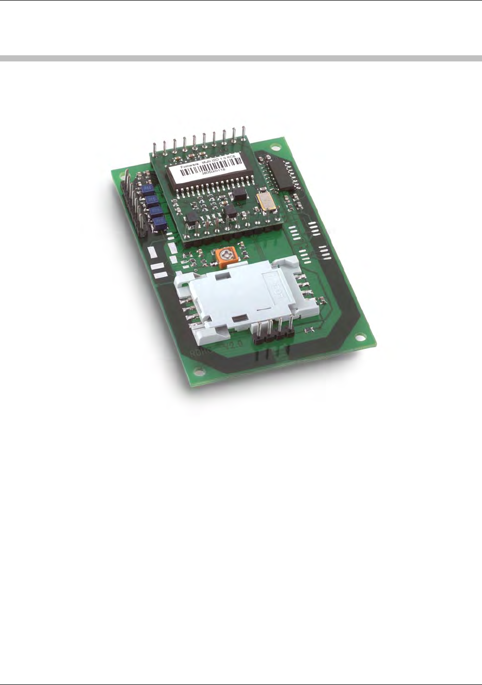
HF Multi ISO RFID Reader User Manual, Firmware V1.4 1508-USM-00-0-04
Appendix D
5553 Reader Board RS232 Compact MultiISO
(RDHC-020xN0-02)
Features
Interface type: RS232
Dimensions: 70x45x12.1 (LxWxH), all in mm
Reading Distance: up to 75mm, depending on the tag
SAM: supported
Boot loader: supported (1)
Drivers: DLL driver available
Antenna: on board
Signaling: reading LED, power LED
Power Supply: 5VDC ± 10% regulated
(1) The boot loader makes it easy to download new firmware to the unit without replacing or
dismantling the hardware.
August 2010 Page 127 of 144
© 2005-2010 HID Global Corporation. All rights reserved.
1508-USM-00-0-04 HF Multi ISO RFID Reader User Manual, Firmware V1.4
Dimensions
All dimensions are listed in millimeters.
1
10 11
20
17 J3
J4
14
SAM Socket
J2
2,80
A
A'
B'
B
70,00 mm
67,00 mm
62,00 mm
58,26 mm
41,06 mm
29,21 mm
7,38 mm
3,00 mm
1,27 mm
3,00 mm
9,43 mm
11,07 mm
26,31 mm
40,83 mm
42,00 mm
43,00 mm
45,00 mm
Figure 13 - 5553 Reader RS232 Compact Multi ISO - Top View
Page 128 of 144 August 2010
© 2005-2010 HID Global Corporation. All rights reserved.
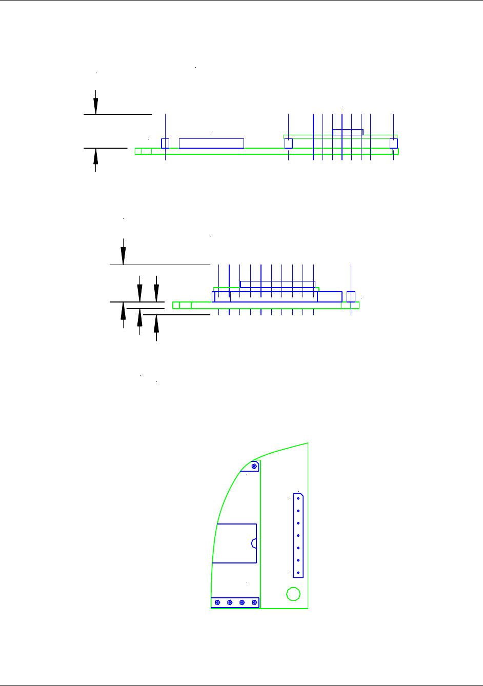
HF Multi ISO RFID Reader User Manual, Firmware V1.4 1508-USM-00-0-04
9,00
View A-A'
J4 J2
J3
Figure 14 - 5553 Reader RS232 Compact Multi ISO - Side View
9,00
1,60 mm
3,10 mm
J3
View B-B'
Figure 15 - 5553 Reader RS232 Compact Multi ISO - Front View
120
17 J3
Figure 16 - Pin Out – Jumper 3
August 2010 Page 129 of 144
© 2005-2010 HID Global Corporation. All rights reserved.
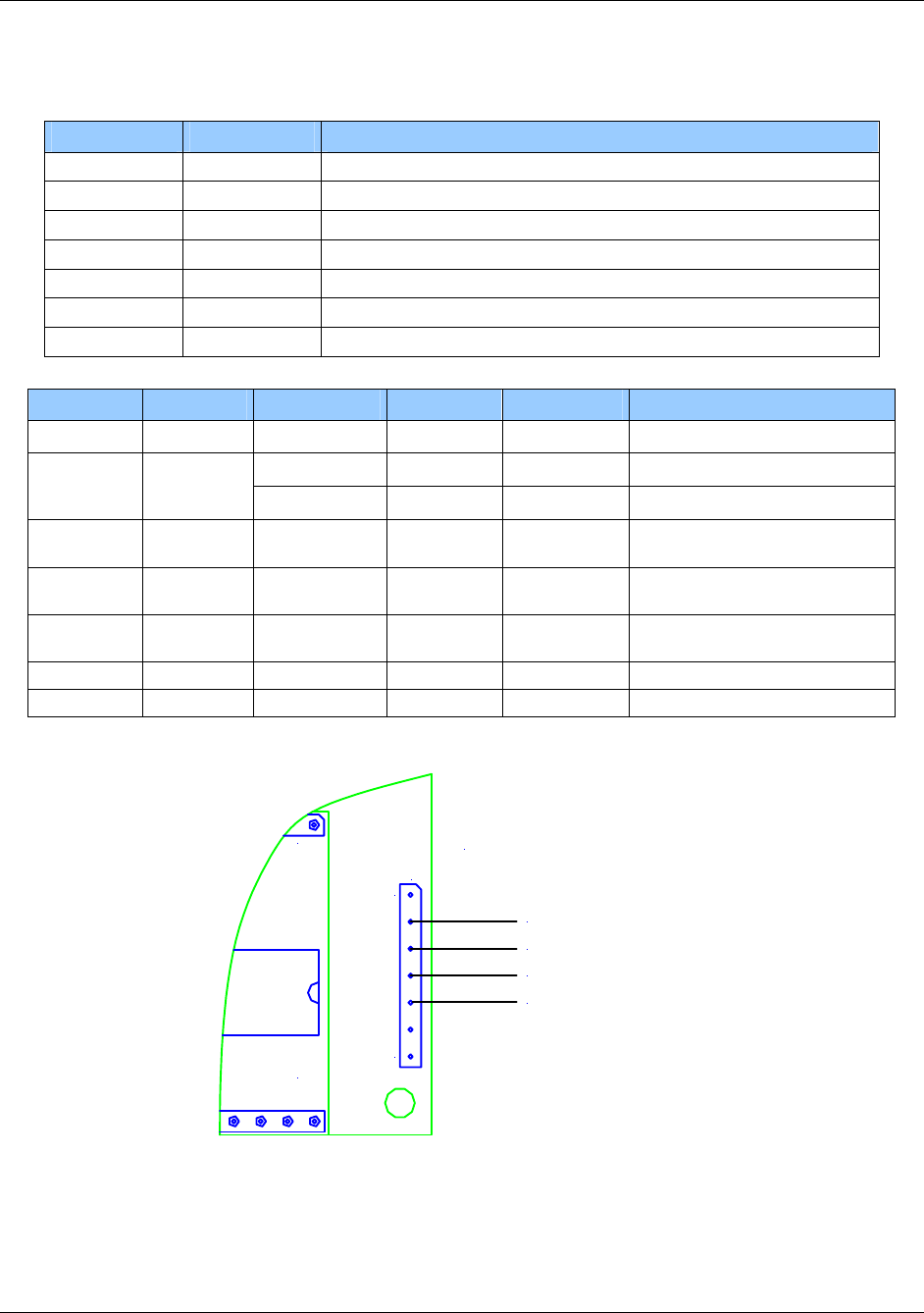
1508-USM-00-0-04 HF Multi ISO RFID Reader User Manual, Firmware V1.4
Table 14 - Pin out – Jumper 3 Detail
PIN PIN No. Description
RFU 1 RFU
+5V 2 Supply Voltage
GND 3 Ground
RX/RXA 4 RS232 RX / RS422 RXA
TX/TXA 5 RS232 TX / RS422 TXA
RXB 6 RS422 RXB
TXB 7 RS422 TXB
Table 15 - J3 pins in RS232 Configuration - Electrical Characteristics
PIN No. Min Typ. Max. Description PIN
RFU 1 Do not connect
4.5V 5V 5.5V Supply Voltage +5V 2
150mA 250mA Supply Current (without SAM)
GND 3 GND Ground for Power Supply and
Interface
RX/RXA 4 -15V
3kΩ
5kΩ +15V
7kΩ RS232 Voltage Levels
Input Impedance
TX/TXA 5 ±5V
300kΩ ±9V RS232 Voltage Levels
Output Impedance
RXB 6 Do not connect
TXB 7 Do not connect
120
17 J3
+5V
Ground
RX
TX
RS232 Configuration
Figure 17 - RS232 Configuration - Jumper 3 Pin Out
Page 130 of 144 August 2010
© 2005-2010 HID Global Corporation. All rights reserved.
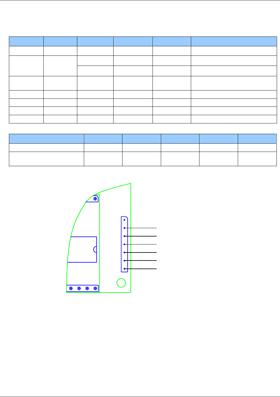
HF Multi ISO RFID Reader User Manual, Firmware V1.4 1508-USM-00-0-04
Table 16 - J3 pins in RS422 Configuration - Electrical Characteristics
PIN No. Min Typ. Max. Description PIN
RFU 1 Do not connect
4.5V 5V 5.5V Supply Voltage +5V 2
150mA 250mA Supply Current (without SAM)
GND 3 GND Ground for Power Supply and
Interface
RX/RXA 4 -7V +12V RXA RS422
TX/TXA 5 -7V +12V TXA RS422 / Differential
RXB 6 -7V +12V RXB RS422
TXB 7 -7V +12V TXB RS422 / Differential
PIN No. Conditions Min Typ. Max. Description
Differential Output Voltage 4/6 Unloaded GND VCC
Differential Output Voltage 5/7 Loaded:
RL=50Ω VCC 2V
120
17 J3
+5V
Ground
RXA
TXA
RS422 Configuration
RXB
TXB
Figure 18 - RS422 Configuration - Jumper 3 Pin Out
August 2010 Page 131 of 144
© 2005-2010 HID Global Corporation. All rights reserved.
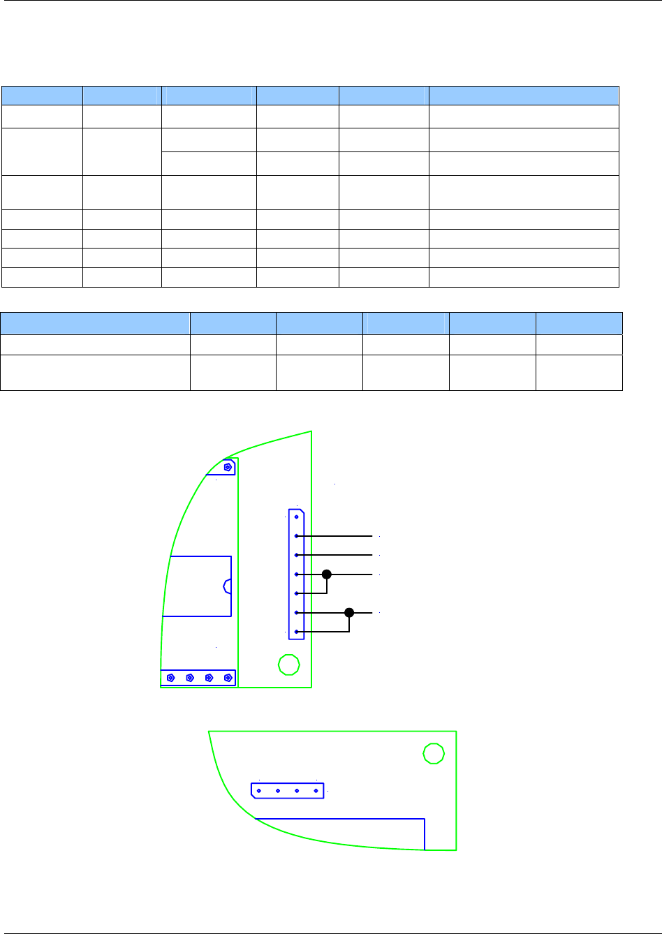
1508-USM-00-0-04 HF Multi ISO RFID Reader User Manual, Firmware V1.4
Table 17 - J3 pins in RS485 Configuration - Electrical Characteristics
PIN No. Min Typ. Max. Description PIN
RFU 1 Do not connect
4.5V 5V 5.5V Supply Voltage +5V 2
150mA 250mA Supply Current (without SAM)
GND 3 GND Ground for Power Supply and
Interface
RX/RXA 4 -7V +12V RX, connect to PIN 5
TX/TXA 5 -7V +12V TX
RXB 6 -7V +12V RX, connect to PIN 7
TXB 7 -7V +12V TX
PIN No. Conditions Min Typ. Max. Description
Differential Output Voltage 4/6 Unloaded GND VCC
Loaded:
RL=270Ω 1.5V VCC Differential Output Voltage 5/7
120
17 J3
+5V
Ground
RXA / TXA
RXB / TXB
RS485 Configuration
Figure 19 – RS485 Configuration - Jumper 3 Pin Out
J4
41
Figure 20 - Jumper 4 Pin Out - Top View
Page 132 of 144 August 2010
© 2005-2010 HID Global Corporation. All rights reserved.
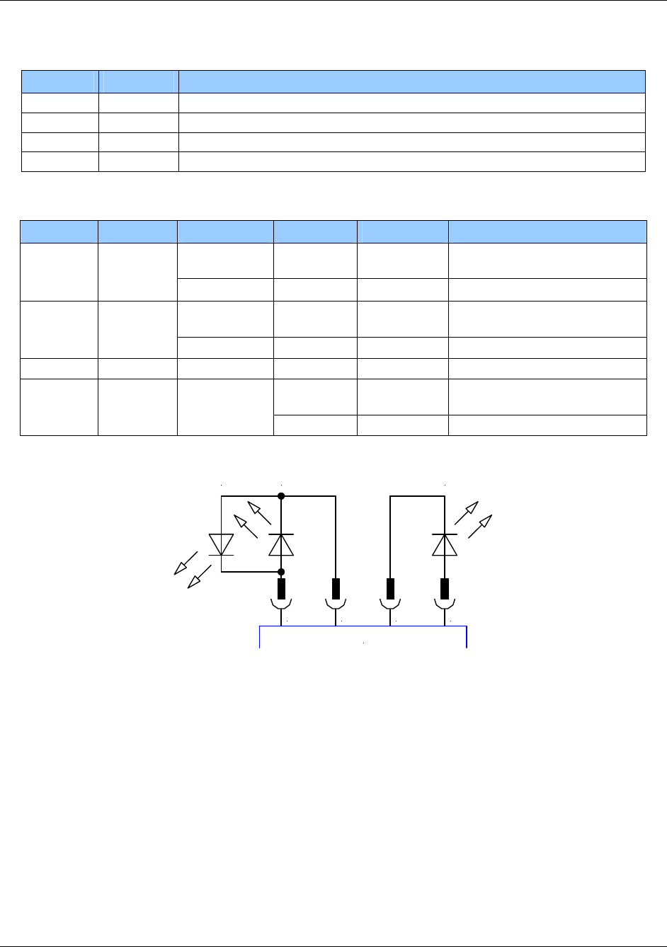
HF Multi ISO RFID Reader User Manual, Firmware V1.4 1508-USM-00-0-04
PIN PIN No. Description
Read+ 1 Connector for green Read Indicator LED
Read- 2 Connector for red Read Error Indicator LED
Power- 3 Ground
Power+ 4 Connector for Power Indicator LED
Table 18 - J4 pins - Electrical Characteristics
PIN No. Min Typ. Max. Description PIN
1.4V
@11mA VDDmax Read+ 1
11mA @15mA
1.4V
@11mA VDDmax Read- 2
11mA @15mA
Power- 3 GND
1.4V
@11mA VDDmax Power+ 4
11mA 15mA
1 2 3 4
J4
LEDgLEDr Power
Figure 21 - Jumper 4 Pin Out
August 2010 Page 133 of 144
© 2005-2010 HID Global Corporation. All rights reserved.
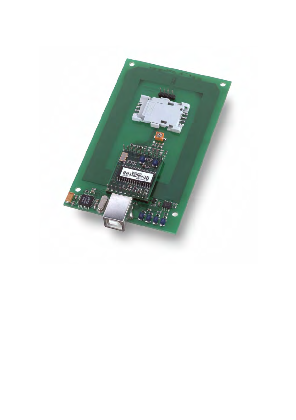
1508-USM-00-0-04 HF Multi ISO RFID Reader User Manual, Firmware V1.4
5553 Reader Board USB Comfort Multi ISO
(RDHS-0204N0-02)
Features
Interface type: USB 2.0
Dimensions: 110x70x14 (LxWxH), all in mm
Reading Distance: up to 90mm, depending on the tag
SAM: supported
Boot loader: supported (²)
Drivers: virtual COM port driver, DLL driver, PCSC driver available
Antenna: on board
Signaling: reading LED, power LED
Power Supply: through USB
(²) The boot loader makes it easy to download new firmware to the unit without replacing or
dismantling the hardware.
Page 134 of 144 August 2010
© 2005-2010 HID Global Corporation. All rights reserved.
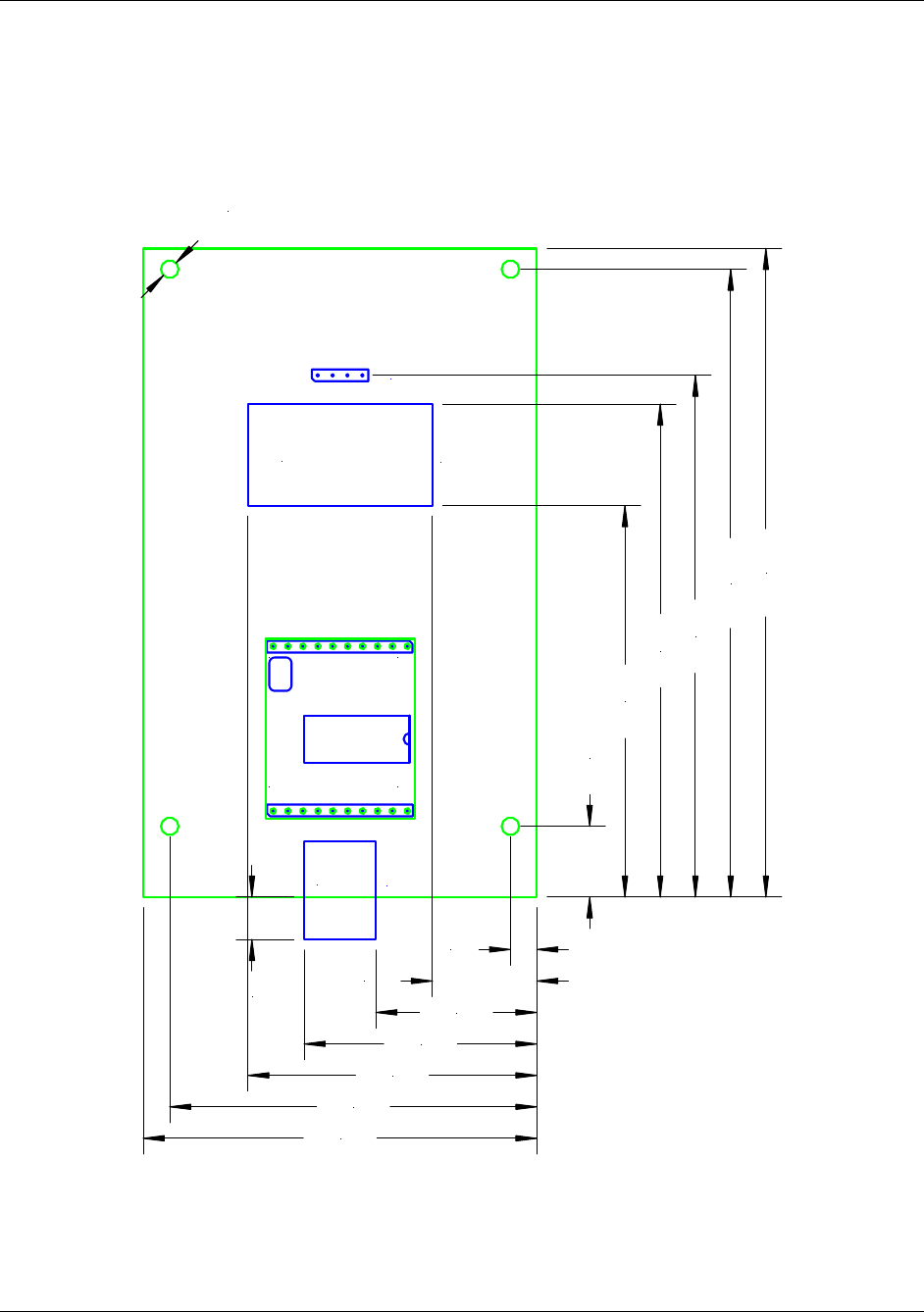
HF Multi ISO RFID Reader User Manual, Firmware V1.4 1508-USM-00-0-04
Dimensions
All dimensions are listed in millimeters.
J2
J5
J3
Read LED +
Read LED -
Power LED +
Power LED -
SAM Socket
USB
1
10 11
20
12,00
66,40
83,60
88,50
106,50
110,00
4,50
17,78
27,40
39,60
49,18
62,50
67,00
7,20
ø 3,00
Figure 22 - 5553 Reader USB Comfort Multi ISO - Top View
August 2010 Page 135 of 144
© 2005-2010 HID Global Corporation. All rights reserved.
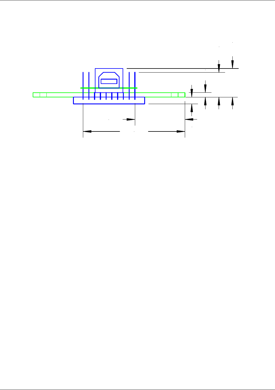
1508-USM-00-0-04 HF Multi ISO RFID Reader User Manual, Firmware V1.4
2,00
11,00
12,70
3,00
22,07
44,93
Figure 23 - 5553 Reader USB Comfort Multi ISO - Front View
Page 136 of 144 August 2010
© 2005-2010 HID Global Corporation. All rights reserved.
HF Multi ISO RFID Reader User Manual, Firmware V1.4 1508-USM-00-0-04
J2
J3
SAM Socket
USB
Read LED
(Option 1) Power LED
(Option 1)
Power LED
(Option 2)
Read LED
(Option 2)
31,00
106,70
21,00
46,00
Figure 24 - 5553 Reader USB Comfort Multi ISO - Bottom View
August 2010 Page 137 of 144
© 2005-2010 HID Global Corporation. All rights reserved.
1508-USM-00-0-04 HF Multi ISO RFID Reader User Manual, Firmware V1.4
J5
Read LED +
Read LED -
Power LED +
Power LED -
1 4
Figure 25 - 5553 Reader USB Comfort Multi ISO - Jumper 5 Pin Out - Top View
Table 19 - Pin Out of Jumper 5
PIN PIN No. Description
Read+ 1 Connector for green Read Indicator LED
Read- 2 Connector for red Read Error Indicator LED
Power- 3 Ground
Power+ 4 Connector for Power Indicator LED
Electrical characteristics of J5 pins
Table 20 – J5 Pin - Electrical Characteristics
PIN No. Min Typ. Max. Description PIN
1.4V
@11mA VDDmax Read+ 1
11mA @15mA
1.4V
@11mA VDDmax Read- 2
11mA @15mA
Power- 3 GND
1.4V
@11mA VDDmax Power+ 4
11mA 15mA
Page 138 of 144 August 2010
© 2005-2010 HID Global Corporation. All rights reserved.
HF Multi ISO RFID Reader User Manual, Firmware V1.4 1508-USM-00-0-04
5553 Desktop Multi ISO (RDHS-0204D0-02)
Features
Interface type: USB 2.0
Dimensions: 155x82x35 (LxWxH), all in mm
Reading Distance: up to 80mm, depending on the tag
SAM: supported
Boot loader: supported (²)
Drivers: virtual COM port driver, DLL driver, PCSC driver available
Antenna: on board
Signaling: reading LED, power LED
Power Supply: through USB
(²) The boot loader makes it easy to download new firmware to the unit without replacing or
dismantling the hardware.
August 2010 Page 139 of 144
© 2005-2010 HID Global Corporation. All rights reserved.
1508-USM-00-0-04 HF Multi ISO RFID Reader User Manual, Firmware V1.4
4553 Mobile Multi ISO (RDHP-0206P0-02)
Features
Interface type: CF Card Type II
Dimensions: (LxWxH) 86.50x43.0x10.0mm ± 0.1mm (LxWxH)
Reading Distance: up to 60mm, depending on the tag
SAM: not integrated
Boot loader: supported (²)
Drivers: virtual COM port driver, DLL driver available
Antenna: integrated
Signaling: reading LED integrated
Power Supply: through CF Card Interface
(²) The boot loader makes it easy to download new firmware to the unit without replacing or
dismantling the hardware.
Page 140 of 144 August 2010
© 2005-2010 HID Global Corporation. All rights reserved.

HF Multi ISO RFID Reader User Manual, Firmware V1.4 1508-USM-00-0-04
Appendix E - Version History
Date Description Firmware
Version Document
Revision
07/16/2010 Removed Paypass; added EMVCO. Modified High
Speed Select Wait and ‘e’ commands. Version 1.4 Rev D.0
11/30/2009 Corrected sample ‘e’ message
Added recommendation for using RAW message
type
Removed ambiguous description for MCLR pin
Version 1.3.1 Unreleased (A.1)
07/23/2009 Version 1.3 Rev C.0
07/07/2009 Contents of the Security Manual incorporated
Command table hyperlinks added
Explanations clarified and examples added
Text updated to reflect latest Brand names
Version 1.2 Rev B.0
10/22/2008 Extended ID supports the ISO 14443 A SAK byte
High Level support of the Innovision Jewel tag
(selection, read and write operations)
Added functionality to switch between ReqA/B or
WupA/B usage
The Quiet command now supports ISO 14443
part 3 and 4.
Improved ISO 14443 4 handling
Changed LED behavior in continuous read mode
and multi-list
Increased LED flash duration time
New command "ox" added to reread all register
settings
Basic Paypass 1.0 functionality
Improved SAM handling & support for new NXP
SAM.
Version 1.2 Rev. A.0
09/06/2006 Register default value changed for Selection
Timeout ISO 14443 B
Support of asynchronous baud rates for the high-
speed select command
Improved support of read / write operations for
LRI tags
Added commands to read and write multiple
blocks ('rd' / 'wd')
Flag added to disable read after write
Bug fixes
Version 1.1 Rev. 1.0
09/02/2005 Initial Release Version 1.0 Rev. 1.0
August 2010 Page 141 of 144
© 2005-2010 HID Global Corporation. All rights reserved.

1508-USM-00-0-04 HF Multi ISO RFID Reader User Manual, Firmware V1.4
Appendix F - Approvals / Certificates
CE Declaration
HID Global declares that, in conformity with the European CE requirements specified
in the EMC Directive 89/336/EEC, the HID HF Multi ISO Plug & Play Modules, the HID
HF Multi ISO Desktop Reader and the Plug-In Reader Module, described in this
manual, are
CE compliant
The relevant documents are available.
If any of the Multi ISO Plug & Play Modules or the CF Card Reader Module is operated
from a mains power supply, all power connections and additional components of the
final device must also comply with the EMC Directive 89/336/EEC directive.
Customers selling into Europe must themselves make sure that the final device
conforms to the EMC Directive 89/336/EEC directive.
The compliance of important international regulations into business practices are a
priority and the implementation of the EMC Directive 89/336/EEC is fully in line with
the company’s commitment to continuously improve its Quality Management System.
Page 142 of 144 August 2010
© 2005-2010 HID Global Corporation. All rights reserved.

HF Multi ISO RFID Reader User Manual, Firmware V1.4 1508-USM-00-0-04
FCC Declaration
HID Global declares that, in conformity with the U.S. Directive FCC part 15, HID HF
Multi ISO Plug & Play Modules, the HID HF Multi ISO Desktop Reader and the Plug-In
Reader Module, described in this manual, are
FCC part15 compliant
The relevant documents are available.
If any of the Multi ISO Plug & Play Modules or the CF Card Reader Module is operated
from a mains power supply, all power connections and additional components of the
final device must also comply with the US FCC Part 15 directive.
Customers selling into the USA must themselves make sure that the final device
conforms to the US FCC Part 15 directive.
Caution: Any changes or modifications not expressly approved by the party
responsible for compliance could void the user's authority to operate the equipment.
For HID Identification Technologies GmbH, the compliance of important international
regulations into business practices are a priority and the implementation of the FCC
part 15 is fully in line with the company’s commitment to continuously improve its
Quality Management System.
This device complies with part 15 of the FCC Rules. Operation is subject to the
following two conditions: (1) This device may not cause harmful interference, and
(2) this device must accept any interference received, including interference that
may cause undesired operation.
August 2010 Page 143 of 144
© 2005-2010 HID Global Corporation. All rights reserved.

1508-USM-00-0-04 HF Multi ISO RFID Reader User Manual, Firmware V1.4
Page 144 of 144 August 2010
© 2005-2010 HID Global Corporation. All rights reserved.
RoHS Compliance
HID Global declares that, in conformity with the Directive 2002/95/EC about the
Restriction of Hazardous Substances (RoHS), its HID HF Multi ISO RFID Reader
products, listed in this manual, are
RoHS compliant
The following substances are contained in accordance with the limits required by
the Directive.
Cadmium and cadmium compounds
Lead and lead compounds
Mercury and mercury compounds
Hexavalent chromium compounds
Polybrominated biphenyls (PBB)
Polybrominated Diphenylethers (BPDE)
For HID Global, the integration of environmental considerations into business
practices is a priority and the implementation of RoHS Directive is fully in line with
the company’s commitment to continuously improve its Quality Management System.