HID Global 6015 User Manual I Master 5 5 900 5 90
HID Global Corporation I Master 5 5 900 5 90
UserManual.wiki
>
HID Global
>
6015 User Manual
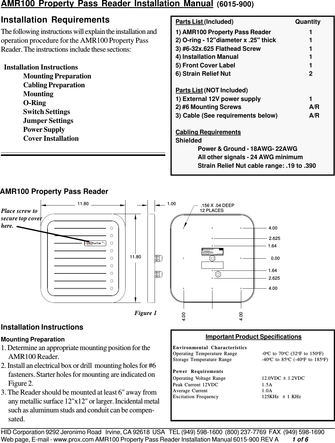
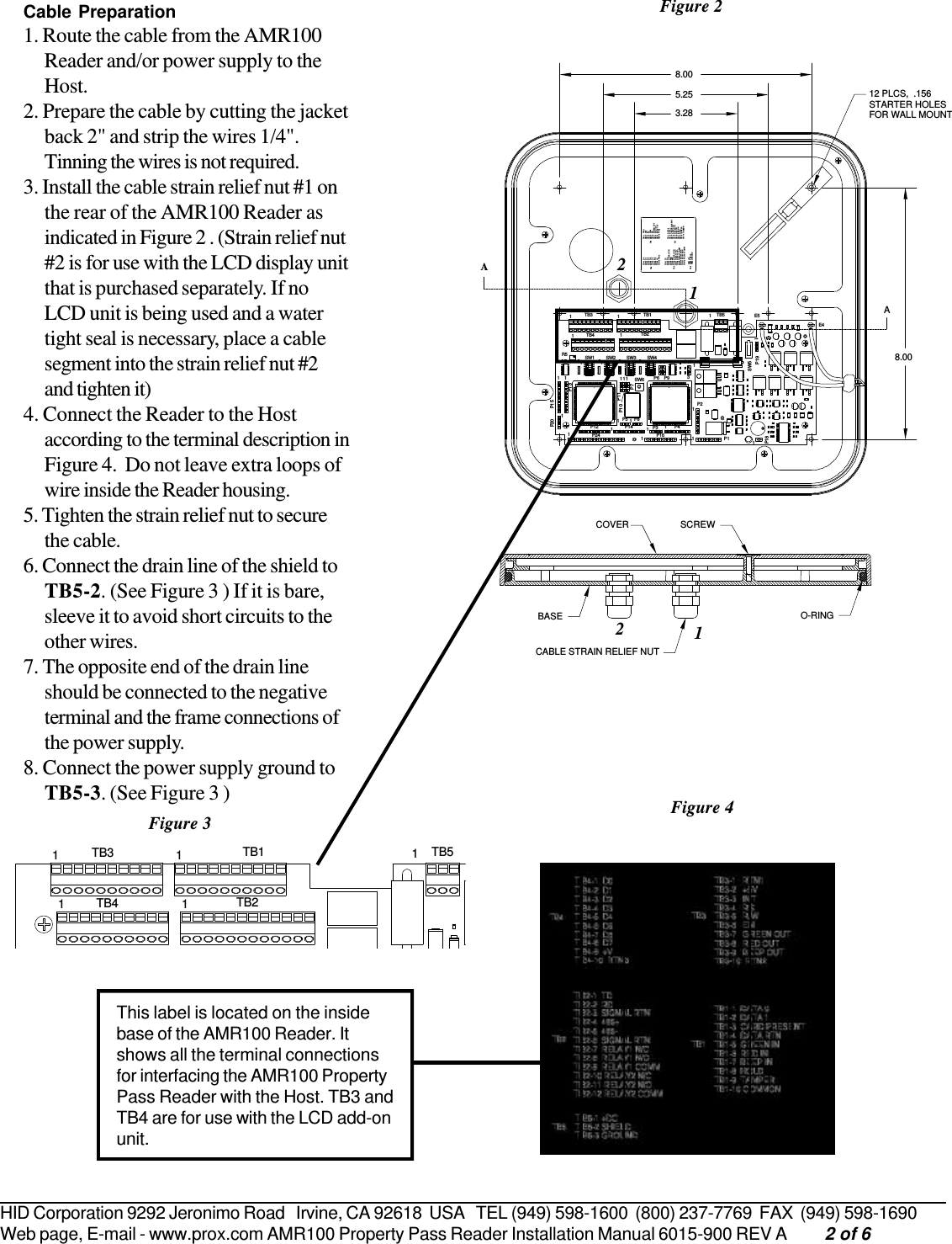
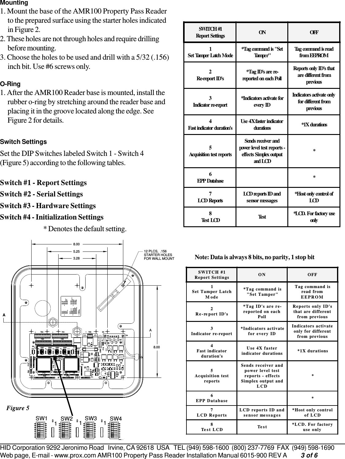
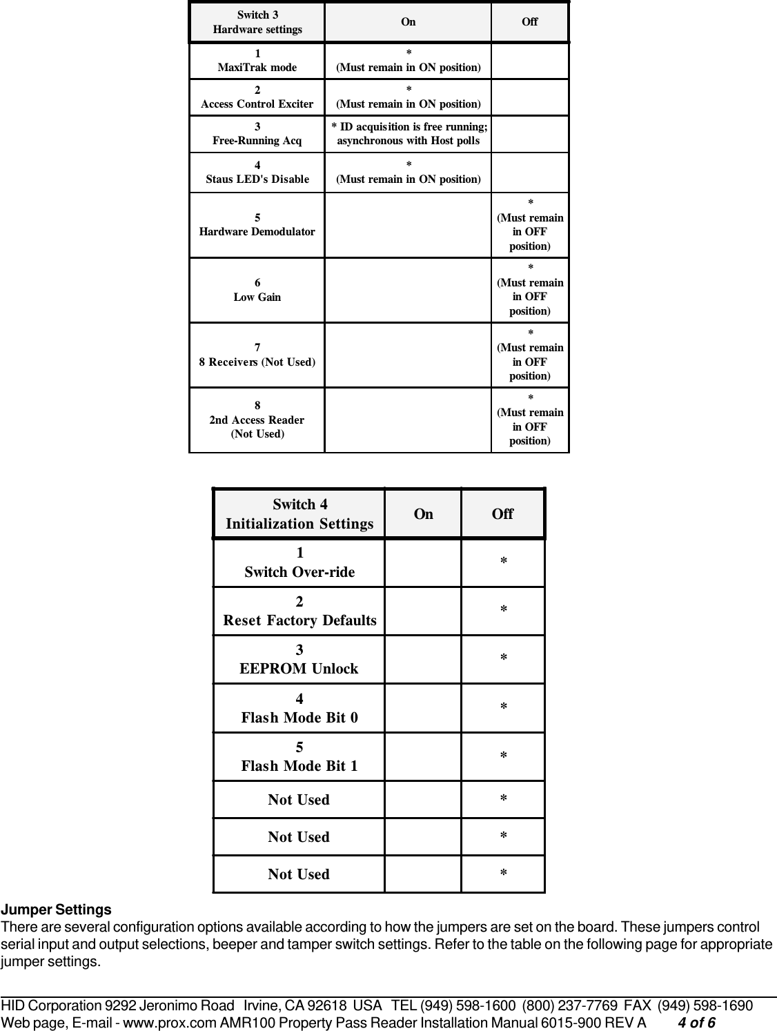
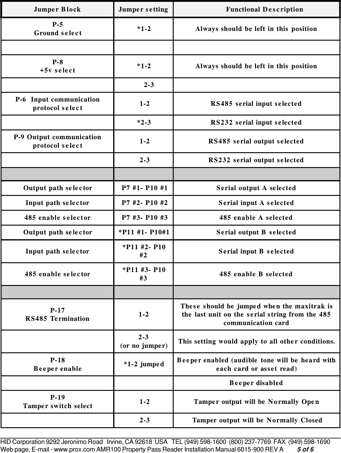
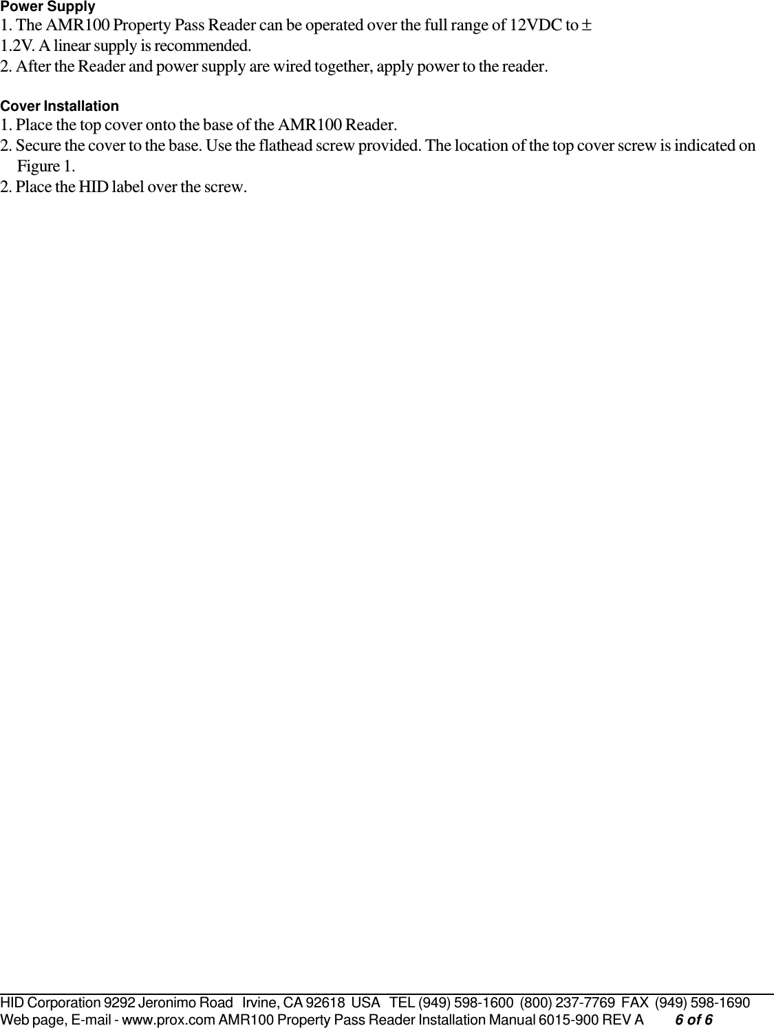
AMR100 Property Pass Reader Installation Manual
Navigation menu
Upload a User Manual
Namespaces
Wiki Guide
HTML
PDF
Info
Views
User Manual
Discussion / Help
Navigation