HID Global 6015 User Manual I Master 5 5 900 5 90
HID Global Corporation I Master 5 5 900 5 90
AMR100 Property Pass Reader Installation Manual
HID Corporation 9292 Jeronimo Road Irvine, CA 92618 USA TEL (949) 598-1600 (800) 237-7769 FAX (949) 598-1690
Web page, E-mail - www.prox.com AMR100 Property Pass Reader Installation Manual 6015-900 REV A 1 of 6
HID ProxTrak
TM
This de vi ce c ompli es with pa rt 15 of the FCC
may ca us e u nd es ired op era tio n.
inte rfere nc e re ci ev ed, in cl udi ng in terfe ren ce tha t
inte rfere nc e, a nd (2) T his d ev ic e mus t ac c ept an y
con dit ion s: (1) T his d ev ic e may no t c aus e harmful
rules . Ope rati on is s ubj ec t to th e fo ll owin g two
1998 HID CORPORATION
U.S. PATENT NO. 4,7 30 ,18 8 5 ,04 1,6 25
C
FCC ID: JQ6601 5
ELECTRICAL RATING: 1 0.8 -13. 2VDC/25 0mA
REFER TO OPERATORS MANUAL 601 5-90 0.
ACCESS CONTROL SYSTEM UNIT ACCESSORY.
8T29
R
LISTED
HID CORPORATION
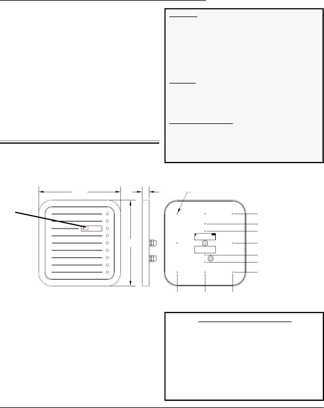
11.80 1.00
11.80
.156 X .04 DEEP
12 PLACES
0.00
1.64
2.625
4.00
1.64
2.625
4.00
4.00
4.00
Installation Requirements
The following instructions will explain the installation and
operation procedure for the AMR100 Property Pass
Reader. The instructions include these sections:
Installation Instructions
Mounting Preparation
Cabling Preparation
Mounting
O-Ring
Switch Settings
Jumper Settings
Power Supply
Cover Installation
AMR100 Property Pass Reader
AMR100 Property Pass Reader Installation Manual (6015-900)
Installation Instructions
Mounting Preparation
1. Determine an appropriate mounting position for the
AMR100 Reader.
2. Install an electrical box or drill mounting holes for #6
fasteners. Starter holes for mounting are indicated on
Figure 2.
3. The Reader should be mounted at least 6" away from
any metallic surface 12"x12" or larger. Incidental metal
such as aluminum studs and conduit can be compen-
sated.
Figure 1
Important Product Specifications
Environmental Characteristics
Operating Temperature Range -0oC to 70oC (32oF to 150oF)
Storage Temperature Range -40oC to 85oC (-40oF to 185oF)
Power Requirements
Operating Voltage Range 12.0VDC ± 1.2VDC
Peak Current 12VDC 1.5A
Average Current 1.0A
Excitation Frequency 125KHz ± 1 KHz
Parts List (Included) Quantity
1) AMR100 Property Pass Reader 1
2) O-ring - 12"diameter x .25" thick 1
3) #6-32x.625 Flathead Screw 1
4) Installation Manual 1
5) Front Cover Label 1
6) Strain Relief Nut 2
Parts List (NOT Included)
1) External 12V power supply 1
2) #6 Mounting Screws A/R
3) Cable (See requirements below) A/R
Cabling Requirements
Shielded
Power & Ground - 18AWG- 22AWG
All other signals - 24 AWG minimum
Strain Relief Nut cable range: .19 to .390
Place screw to
secure top cover
here.
HID Corporation 9292 Jeronimo Road Irvine, CA 92618 USA TEL (949) 598-1600 (800) 237-7769 FAX (949) 598-1690
Web page, E-mail - www.prox.com AMR100 Property Pass Reader Installation Manual 6015-900 REV A 2 of 6
E4
E5
P19
SW5
P18
1
1
TB4
TB4-1 D0
TB4-2 D1
TB4-3 D2
TB4-4 D3
TB4-5 D4
TB4-6 D5
TB4-7 D6
TB4-8 D7
TB4-9 +V
TB2
TB2-1 TD
TB2-2 RD
TB2-3 SIGNAL RTN
TB2-4 485+
TB2-5 485-
TB2-6 SIGNAL RTN
TB2-7 RELAY1 N/C
TB2-8 RELAY2 N/O
TB2-9 RELAY1 COMM
TB2-10 RELAY2 N/C
TB2-11 RELAY2 N/O
TB2-12 RELAY2 COMM
TB3
TB3-1 RTN1
TB3-2 +5V
TB3-3 INT
TB3-4 RS
TB3-5 R/W
TB3-6 EN
TB3-7 GREEN OUT
TB3-8 RED OUT
TB3-9 BEEP OUT
TB3-10 RTN2
TB1
TB1-1 DATA 0
TB1-2 DATA 1
TB1-3 CARD PRESENT
TB1-4 DATA RTN
TB1-5 GREEN IN
TB1-6 RED IN
TB1-7 BEEP IN
TB1-8 HOLD
TB1-9 TAMPER
TB1-10 COMMON
TB5
TB5-1 +DC
TB5-2 SHIELD
TB5-3 GROUND
TB4-10 RTN3
TB5
1
P2
1
P11
P41
P17 1
3
TB3
TB4
TB1
TB2
SW1
R5 SW2 SW3 SW4
SW6
P12 P14
P8P5
P3
P16
P24 1
11
1
1
1
1 1
1 1 1 1 1 1
111
11
1
11
1
P7
P10P11
P15
P13
P20
P9P6
A
3.28
5.25
8.00
8.00
12 PLCS, .156
STARTER HOLES
FOR WALL MOUNT
CABLE STRAIN RELIEF NUT
BASE
SCREW
O-RING
COVER
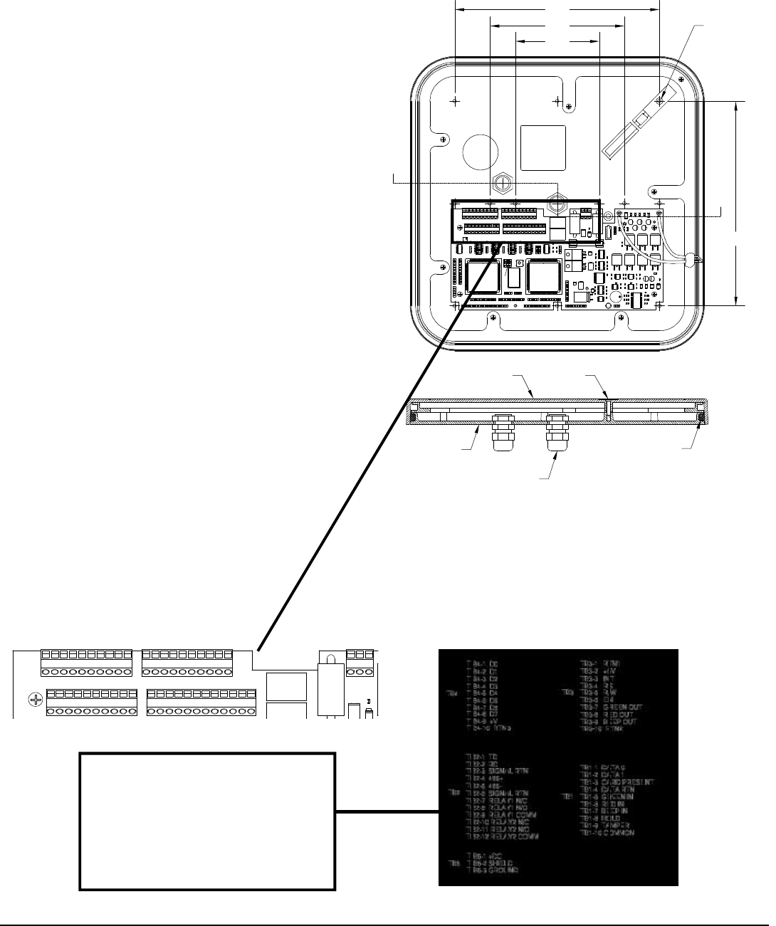
Cable Preparation
1. Route the cable from the AMR100
Reader and/or power supply to the
Host.
2. Prepare the cable by cutting the jacket
back 2" and strip the wires 1/4".
Tinning the wires is not required.
3. Install the cable strain relief nut #1 on
the rear of the AMR100 Reader as
indicated in Figure 2 . (Strain relief nut
#2 is for use with the LCD display unit
that is purchased separately. If no
LCD unit is being used and a water
tight seal is necessary, place a cable
segment into the strain relief nut #2
and tighten it)
4. Connect the Reader to the Host
according to the terminal description in
Figure 4. Do not leave extra loops of
wire inside the Reader housing.
5. Tighten the strain relief nut to secure
the cable.
6. Connect the drain line of the shield to
TB5-2. (See Figure 3 ) If it is bare,
sleeve it to avoid short circuits to the
other wires.
7. The opposite end of the drain line
should be connected to the negative
terminal and the frame connections of
the power supply.
8. Connect the power supply ground to
TB5-3. (See Figure 3 )
Figure 2
TB5
1
TB3
TB4
TB1
TB2
1
1
1
1
Figure 3
This label is located on the inside
base of the AMR100 Reader. It
shows all the terminal connections
for interfacing the AMR100 Property
Pass Reader with the Host. TB3 and
TB4 are for use with the LCD add-on
unit.
Figure 4
1
2
1
2
A
HID Corporation 9292 Jeronimo Road Irvine, CA 92618 USA TEL (949) 598-1600 (800) 237-7769 FAX (949) 598-1690
Web page, E-mail - www.prox.com AMR100 Property Pass Reader Installation Manual 6015-900 REV A 3 of 6
E4
E5
P19
SW5
P18
1
1
TB4
TB4-1 D0
TB4-2 D1
TB4-3 D2
TB4-4 D3
TB4-5 D4
TB4-6 D5
TB4-7 D6
TB4-8 D7
TB4-9 +V
TB2
TB2-1 TD
TB2-2 RD
TB2-3 SIGNAL RTN
TB2-4 485+
TB2-5 485-
TB2-6 SIGNAL RTN
TB2-7 RELAY1 N/C
TB2-8 RELAY2 N/O
TB2-9 RELAY1 COMM
TB2-10 RELAY2 N/C
TB2-11 RELAY2 N/O
TB2-12 RELAY2 COMM
TB3
TB3-1 RTN1
TB3-2 +5V
TB3-3 INT
TB3-4 RS
TB3-5 R/W
TB3-6 EN
TB3-7 GREEN OUT
TB3-8 RED OUT
TB3-9 BEEP OUT
TB3-10 RTN2
TB1
TB1-1 DATA 0
TB1-2 DATA 1
TB1-3 CARD PRESENT
TB1-4 DATA RTN
TB1-5 GREEN IN
TB1-6 RED IN
TB1-7 BEEP IN
TB1-8 HOLD
TB1-9 TAMPER
TB1-10 COMMON
TB5
TB5-1 +DC
TB5-2 SHIELD
TB5-3 GROUND
TB4-10 RTN3
TB5
1
P2
1
P1
1
P41
P171
3
TB3
TB4
TB1
TB2
SW1
R5 SW2 SW3 SW4
SW6
P12 P14
P8P5
P3
P16P24 1
11
1
1
1
1 1
111 1 11
111
1 1
1
1
1
1
P7
P10P11
P15
P13
P20
P9P6
A
3.28
5.25
8.00
8.00
12 PLCS, .156
STARTER HOLES
FOR WALL MOUNT
SW1 SW2 SW3 SW4
11 1
P6
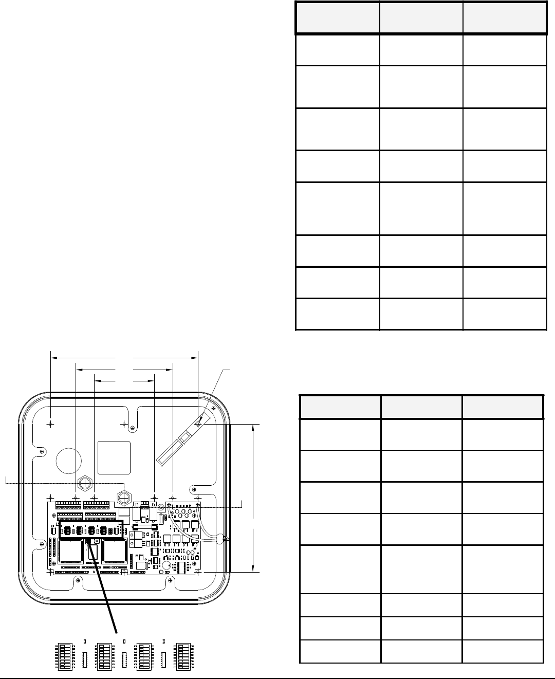
Figure 5
Mounting
1. Mount the base of the AMR100 Property Pass Reader
to the prepared surface using the starter holes indicated
in Figure 2.
2. These holes are not through holes and require drilling
before mounting.
3. Choose the holes to be used and drill with a 5/32 (.156)
inch bit. Use #6 screws only.
O-Ring
1. After the AMR100 Reader base is mounted, install the
rubber o-ring by stretching around the reader base and
placing it in the groove located along the edge. See
Figure 2 for details.
Switch Settings
Set the DIP Switches labeled Switch 1 - Switch 4
(Figure 5) according to the following tables.
Switch #1 - Report Settings
Switch #2 - Serial Settings
Switch #3 - Hardware Settings
Switch #4 - Initialization Settings
* Denotes the default setting.
Note: Data is always 8 bits, no parity, 1 stop bit
A
SWITCH #1
Report Settings ON OFF
1
Set Tamper Latch Mode
*Tag command is "Set
Tamper"
Tag command is read
from EEPROM
2
Re-report ID's
*Tag ID's are re-
reported on each Poll
Reports only ID's that
are different from
previous
3
Indicator re-report
*Indicators activate for
every ID
Indicators activate only
for different from
previous
4
Fast indicator duration's
Use 4X faster indicator
durations *1X durations
5
Acquisition test reports
Sends receiver and
power level test reports -
effects Simplex output
and LCD
*
6
EPP Database *
7
LCD Reports
LCD reports ID and
sensor messages
*Host only control of
LCD
8
Test LCD Test *LCD. For factory use
only
SWITCH #1
Report Settings ON OFF
1
Set Tamper Latch
Mode
*Tag command is
"Set Tamper"
Tag command is
read from
EEPROM
2
Re-report ID's
*Tag ID's are re-
reported on each
Poll
Reports only ID's
that are different
from previous
3
Indicator re-report
*Indicators activate
for every ID
Indicators activate
only for different
from previous
4
Fast indicator
duration's
Use 4X faster
indicator durations *1X durations
5
Acquisition test
reports
Sends receiver and
power level test
reports - effects
Simplex output and
LCD
*
6
EPP Database *
7
LCD Reports
LCD reports ID and
sensor messages
*Host only control
of LCD
8
Test LCD Test*LCD. For factory
use only

HID Corporation 9292 Jeronimo Road Irvine, CA 92618 USA TEL (949) 598-1600 (800) 237-7769 FAX (949) 598-1690
Web page, E-mail - www.prox.com AMR100 Property Pass Reader Installation Manual 6015-900 REV A 4 of 6
Switch 4
Initialization Settings On Off
1
Switch Over-ride*
2
Reset Factory Defaults *
3
EEPROM Unlock *
4
Flash Mode Bit 0 *
5
Flash Mode Bit 1 *
Not Used *
Not Used *
Not Used *
Switch 3
Hardware settings On Off
1
MaxiTrak mode
*
(Must remain in ON position)
2
Access Control Exciter
*
(Must remain in ON position)
3
Free-Running Acq
* ID acquisition is free running;
asynchronous with Host polls
4
Staus LED's Disable
*
(Must remain in ON position)
5
Hardware Demodulator
*
(Must remain
in OFF
position)
6
Low Gain
*
(Must remain
in OFF
position)
7
8 Receivers (Not Used)
*
(Must remain
in OFF
position)
8
2nd Access Reader
(Not Used)
*
(Must remain
in OFF
position)
Jumper Settings
There are several configuration options available according to how the jumpers are set on the board. These jumpers control
serial input and output selections, beeper and tamper switch settings. Refer to the table on the following page for appropriate
jumper settings.

HID Corporation 9292 Jeronimo Road Irvine, CA 92618 USA TEL (949) 598-1600 (800) 237-7769 FAX (949) 598-1690
Web page, E-mail - www.prox.com AMR100 Property Pass Reader Installation Manual 6015-900 REV A 5 of 6
Jumper BlockJumper setting Functional Description
P-5
Ground select*1-2 Always should be left in this position
P-8
+5v select*1-2 Always should be left in this position
2-3
P-6 Input communication
protocol select 1-2 RS485 serial input selected
*2-3 RS232 serial input selected
P-9 Output communication
protocol select 1-2 RS485 serial output selected
2-3 RS232 serial output selected
Output path selector P7 #1- P10 #1 Serial output A selected
Input path selector P7 #2- P10 #2 Serial input A selected
485 enable selector P7 #3- P10 #3 485 enable A selected
Output path selector *P11 #1- P10#1 Serial output B selected
Input path selector *P11 #2- P10
#2 Serial input B selected
485 enable selector *P11 #3- P10
#3 485 enable B selected
P-17
RS485 Termination 1-2
These should be jumped when the maxitrak is
the last unit on the serial string from the 485
communication card
2-3
(or no jumper) This setting would apply to all other conditions.
P-18
Beeper enable *1-2 jumpedBeeper enabled (audible tone will be heard with
each card or asset read)
Beeper disabled
P-19
Tamper switch select 1-2 Tamper output will be Normally Open
2-3 Tamper output will be Normally Closed

HID Corporation 9292 Jeronimo Road Irvine, CA 92618 USA TEL (949) 598-1600 (800) 237-7769 FAX (949) 598-1690
Web page, E-mail - www.prox.com AMR100 Property Pass Reader Installation Manual 6015-900 REV A 6 of 6
Power Supply
1. The AMR100 Property Pass Reader can be operated over the full range of 12VDC to ±
1.2V. A linear supply is recommended.
2. After the Reader and power supply are wired together, apply power to the reader.
Cover Installation
1. Place the top cover onto the base of the AMR100 Reader.
2. Secure the cover to the base. Use the flathead screw provided. The location of the top cover screw is indicated on
Figure 1.
2. Place the HID label over the screw.