HID Global 607XA 6074A HID MIFARE Wiegand Reader User Manual 474681
HID Global Corporation 6074A HID MIFARE Wiegand Reader 474681
Users Manual
REV DESCRIPTION DATE APPROVED
1 6074A INITIAL RELEASE
2 ADDED FCC STATEMENT, FIX LED INPUT
NOTE: Cover sheet is for Revision Control only, and is not to be sent with document.
REV
SHEET 34 35 36 37 38 39 40 41 42 43 44 45 46 47 48 49 50 51
REV
SHEET 16 17 18 19 20 21 22 23 24 25 26 27 28 29 30 31 32 33
REV STATUS A A A A A A A
OF SHEETS 0 1 2 3 4 5 6 7 8 9 10 11 12 13 14 15
TOLERANCES APPROVALS DATE HID CORPORATION
.XX = +/- .03” IRVINE, CALIFORNIA
.XXX = +/- .010” Installation Manual
ANGLES = +/- 1° MIFARE® WIEGAND Reader
MATERIAL N/A
FINISH N/A P/N 6074-901 REV 2
SCALE N/A SIZE A SHEET 0 OF 6

____________________________________________________________________________________________
HID Corporation 9292 Jeronimo Road Irvine, CA 92618-1905 USA TEL (714) 598-1600 (800) 237-7769 FAX (714) 598-1690
Web page, E-mail - www.prox.com MIFARE Wiegand Reader Installation Manual 6074-901 REV 2 1 of 5
Installation Manual – 6074-901 Rev A
HID MIFARE WIEGAND READER 6074A
____________________________________________________________________________________________
HID Corporation 9292 Jeronimo Road Irvine, CA 92618-1905 USA TEL (714) 598-1600 (800) 237-7769 FAX (714) 598-1690
Web page, E-mail - www.prox.com MIFARE Wiegand Reader Installation Manual 6074-901 REV 2 2 of 5
MIFARE WIEGAND Reader Installation Manual
System Overview
The MIFARE Wiegand Reader is a self contained proximity Reader, frequently used in Access Control
Systems. The antenna and all associated electronics are assembled in a polycarbonate housing. The
Reader contains a micro-controller unit that controls an RF field that is generated at 13.56MHz. The
Reader has a sensitive receiver circuit that detects ID card data and passes it along to the micro-
controller for decoding. The Reader output is configured in the "Wiegand" style electrical interface for
model 6074A. The Reader has a single Bicolor LED that will emit red, green or amber colors. Installation
of the MIFARE Wiegand Reader consists of mounting the Reader and connecting the cable to the Host
via the Pigtail.
Operation
Access Cards are to be presented to the front of the Reader. The LED is red when ready to read an ID
card. The LED turns green when the card is read and a message is transmitted to the Host computer or
interface panel. When the system is ready for another card, the LED returns to red. The LED is flashed
green and the Beeper is activated for 500 milliseconds when they are controlled by the internal micro-
controller. The operation of the LED and beeper is often controlled by the Host panel. If Host controlled,
the operation will deviate from Host to Host. The MIFARE Wiegand reader’s default configuration can
accept green and beeper input control lines that allows control of green LED and beeper only (Red input
is not supported).
Parts List Quantity
1) MIFARE Wiegand Reader 1 (included)
2) #6-32 x 1" self tapping, Type T or 23 2 (included)
3) This Installation Sheet 1 (included)
4) Wire Splice 9 (installer supplied)
5) Grommet 1 Recommended (installer supplied)
6) DC Power Supply 10.0 to 14.0VDC, 50mA 1 (installer supplied)
7) Cable, 9 conductor , 22 AWG Up to 500ft. (installer supplied) Alpha 1295C
See Cable Notes
Installation Procedure:
1. Determine an appropriate mounting position for the Reader. Drill two 7/64th (.109) Inch holes for
mounting the Reader to the surface (see figure 1). Drill a 3/8 to 1.0 Inch hole for the cable. Place a
grommet around the edge of the hole. Route the interface cable from the Reader and/or power
supply to the Host. Check all electrical codes for proper cable installation.
2. The MIFARE Wiegand Reader is a Pigtail style with a 18” - 9 conductor cable. Prepare the new
cable by cutting the cable jacket back 1-1/4” and strip the wires ¼”. Splice the cable and the pigtail
together and seal the splice. Trim and cover all conductors that are not used.
3. Connect the Reader and Host together according to the wiring diagram with figure 2 and the Host
installation guide. The legend for wiring is color coded (according to the "Wiegand Standard") for the
recommended cable.
4. After wiring the Reader and power supply, the Reader is ready to be tested. Power up the Reader
and the red LED will be on when operating under the factory default reader configuration. This
indicates that the micro-controller unit is working properly. Present an ID card to the Reader and the
LED should momentarily turn green, indicating a read of the card. If the Reader LED is controlled by
the Host refer to the Host description of the LED operation.
5. Mount the Reader with the provided screws when mounting onto metal mullions or junction boxes.
On other materials use the appropriate fastener.
____________________________________________________________________________________________
HID Corporation 9292 Jeronimo Road Irvine, CA 92618-1905 USA TEL (714) 598-1600 (800) 237-7769 FAX (714) 598-1690
Web page, E-mail - www.prox.com MIFARE Wiegand Reader Installation Manual 6074-901 REV 2 3 of 5
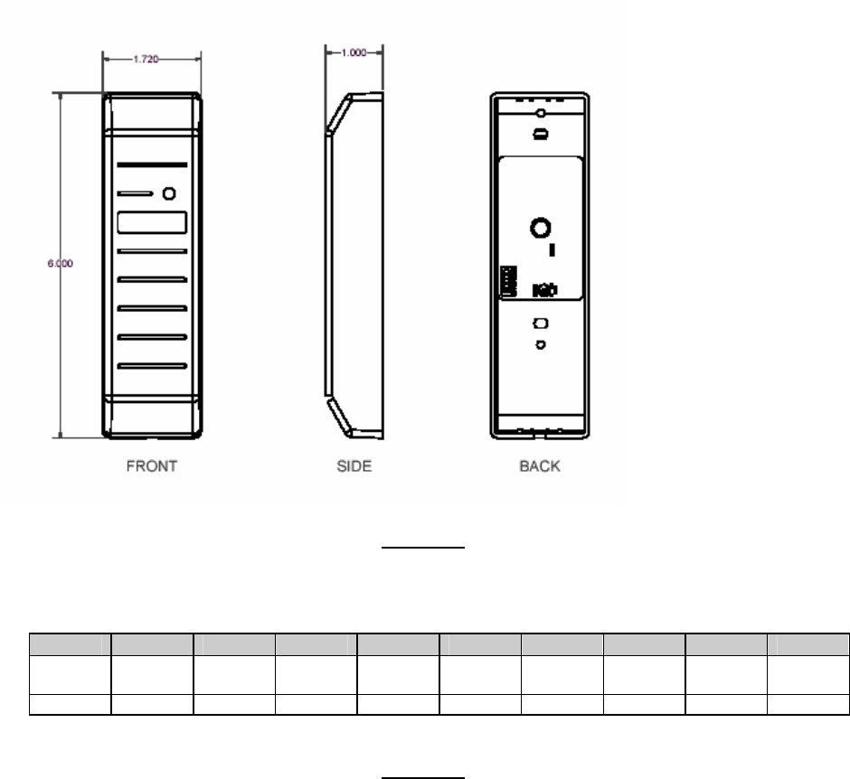
Dimension Diagrams, front, side and back views
FIGURE 1
Wire Connections
1 2 3 4 5 6 7 8 9 10
+DC Ground Data0 Data1 Shield
Ground
Green
LED
Red
LED
Beeper --- ---
Red Black Green White Drain Orange Brown Yellow --- ---
FIGURE 2
Cable Notes
1) Wiegand - +DC, Ground, Shield Ground, Data0 and Data1 are required for Wiegand Operation. All
others (Green LED, Red LED, and Beeper) are optional.
2) When using a separate power supply for the MIFARE Wiegand Reader, the power supply and Host
should have a common ground (voltage reference).
3) If the Host is controlling the beeper or the LEDs are configured for the external LED mode, additional
conductors will be required. The recommended cables are Alpha 1295C, 1296C, 1297C, 1298C and
1299C, which are five, six, seven, eight and nine conductors respectively. Larger wire gauges are
acceptable. The wire is to be stranded with an overall foil shield plus the drain wire.
4) The Cable shield (drain) should be connected to the earth ground at the panel or power supply end of
the cable. Also, for emissions compliance, tie earth ground and common together at the power supply.
This configuration is the best for shielding the reader cable from external interference and reducing the
likelihood of the Reader causing interference. Changes or modifications not expressly approved by the
party responsible for compliance could void the user’s authority to operate the equipment.
____________________________________________________________________________________________
HID Corporation 9292 Jeronimo Road Irvine, CA 92618-1905 USA TEL (714) 598-1600 (800) 237-7769 FAX (714) 598-1690
Web page, E-mail - www.prox.com MIFARE Wiegand Reader Installation Manual 6074-901 REV 2 4 of 5
Testing and Operation
When power is applied to the reader the LED will turn – on Red. This indicates that the microcontroller is
operating properly. Present an ID card to the reader. The LED will momentarily turn green while the
beeper beeps once, indicating that the card was read successfully. In normal operation, the Red LED is
normally on and the Green LED flashes on a valid card read. The Green LED and Beeper respond when
their respective user input line is pulled low. There is no operation for the Red LED user input.
Please note that typical read range for MIFARE cards is 1.5 – 2.0” (37-50 mm).
Card Compatibility
The HID MIFARE Reader reads serial number data from these cards: HID MIFARE, Any Philips
compatible MIFARE Standard contactless smart card. The reader will read the MIFARE Card Serial
Number only from all MIFARE cards, including MIFARE Lite and MIFARE Pro cards.
*The HID MIFARE reader will not read 125 kHz HID Proximity cards.
CSN Read Only Mode
In CSN Only mode, the reader reads the 32-bit MIFARE random card serial number (CSN or UID) from
any MIFARE card, including MIFARE Lite, MIFARE Standard and MIFARE Pro, outputting that data
in a 40-bit Wiegand format - 32-bit CSN + 8 bit checksum format.
Sector Read Only Mode
In Sector Read Only Mode the reader reads and outputs a specified number of bits from a specified
sector based on reader configuration. The following reader attributes can be configured at the factory to
meet individual needs.
• Application sector (0 – 15)
• Application Block (0-2)
• Sector Key
• Number of Bits Output (1-128)
• Starting Bit Number (0-127)
• Audio/Visual feedback (ON/Off)
Product Configuration/Ordering Options
6074 A X X XX -XXXX Y
Customer Custom Artwork or Firmware Number - 1 through 9, A
through Z
Customer Custom Number
Configuration Options - (00 standard)
Standard Hardware Options - P = Pigtail
Color - G = Gray
Current Revision Letter
Model Number 6074 = MIFARE Wiegand
¾ Standard Wiegand Part Number = 6074AGP00 is a MIFARE Wiegand, Gray Standard (1”)
housing, Potted, with 9 conductor, 18” Pigtail.
____________________________________________________________________________________________
HID Corporation 9292 Jeronimo Road Irvine, CA 92618-1905 USA TEL (714) 598-1600 (800) 237-7769 FAX (714) 598-1690
Web page, E-mail - www.prox.com MIFARE Wiegand Reader Installation Manual 6074-901 REV 2 2 of 5
Product Specifications
Read Distance
¾ Overall Operating Limits (10VDC - minimum) 1.0-1.5 inches (2.5-3.8 cm)
¾ Non-Metallic Mounting (12VDC - typical) 1.0-1.5 inches (2.5-3.8 cm)
¾ Mounted on Metal (12VDC - typical) 1.0-2.5 inches (2.5-3.8 cm)
Environmental Characteristics
¾ Operating Temperature Range -30oC to 65oC (-22oF to 150oF)
¾ Storage Temperature Range -40oC to 85oC (-40oF to 185oF)
¾ Operating Humidity Range 5% to 95% non-condensing
¾ Operating Vibration Limit .04 g2/Hz 20-2000Hz
¾ Operating Shock Limit 30g, 11mS, Half Sine
¾ Potting Material UL Recognized Filled Polyurethane
¾ Enclosure Material UL Recognized Lexan Polycarbonate
¾ Potted Weight 8.2oz (228grms)
Power Requirements
¾ Power supply Linear type recommended
¾ Operating Voltage Range (+DC) 10.0VDC -14.0VDC
¾ Absolute Maximum (+DC non-operating) 14.0VDC
¾ Maximum Average Current at 12V 60mA
¾ Transient Protection (all terminals) 8,000 volts
¾ Reverse Voltage Protection -15V on all I/O and -35 for power lines
¾ Input Voltage (maximum data-0/1 lines) 15.0VDC
¾ Input Voltage (maximum interface lines) 15.0VDC
Operating Parameters
¾ Excitation Frequency 13.56MHz
¾ Read and Report Speed (26 bit Wiegand Card) 200mS (1K card) + output data
¾ Maximum Cable Distance to Host 500 feet (152 meters)
¾ LED Type Bi-colored Red/Green
¾ LED Operation (host control of red/green) <.5V on LED control line
¾ Beeper Operation (host control) <.5V on beeper line
¾ Beeper Control (default) Beeper enabled
FCC Compliance Statement:
This device complies with part 15 of the FCC rules. Operation is subject to the following two
conditions: (1) this device may not cause harmful interference, and (2) this device must accept
any interference received, including interference that may cause undesired operation.
NOTE: THE ABOVE ARE RECOMMENDED INSTALLATION PROCEDURES. ALL LOCAL, STATE
AND NATIONAL ELECTRICAL CODES TAKE PRECEDENCE.