HID Global SDC1000 Door Access Controller User Manual SDC1000 MANUAL
HID Global Corporation Door Access Controller SDC1000 MANUAL
Manual
MOTOROLA
SDC1000
SINGLE DOOR ACCESS CONTROLLER
- 1 -
OPERATING MANUAL
MOTOROLA SDC1000

MOTOROLA
SDC1000
SINGLE DOOR ACCESS CONTROLLER
- 2 -
CONTENTS
1. Important Safety Instructions
2. General
3. Features
4. Specifications
5. Name of the Parts
6. Identifying supplied parts
7. Installation of the Product
8. Wire Color Table of the Main Unit
9. Wire Connection in of basic application
10. Initial Setup
11. Operation
12. Setting Changes
13. FCC REGISTRATION INFORMATION
14. Warranty and Service

MOTOROLA
SDC1000
SINGLE DOOR ACCESS CONTROLLER
- 3 -
1. Important Safety Instructions
When using your door access controller, basing safety precautions should always be followed to reduce the risk of fire,
electrical shock, and injury to persons including following:
1. Read and understand all instructions.
2. Follow all warnings and instructions marked on the product
3. Do not use liquid cleaners, or aerosol cleaners. Use a damp cloth for cleaning. if necessary, use a mild soap.
4. Do not use this product near water, for example near a bath tub, wash bowl, kitchen sink, or laundry tub, in a wet
basement, or near a swimming pool.
5. This product should be operated only from the type of power source indicated on the marking label. if you are not sure of
the type of power supply to your home, consult your dealer or local power company.
6. Never push objects of any kind into this product though the cabinet slots as they may touch voltage points or short out
parts that could result in a risk of fire or electric shock. Never spill liquid of any kind on the product.
7. To reduce the risk of electric shock, do not disassemble this product, but take it to a qualified serviceman when some
service or repair work is required. Opening or removing covers may expose you to dangerous voltages or other risks.
incorrect reassembly can cause electric shock when the appliance is subsequently used.
8. Unplug this product from the wall outlet and refer to qualified service personnel under the following conditions:
a. When the power supply cord or plug is damaged or frayed.
b. If liquid has been spilled into the product
c. If the product has exposed to rain or water.
d. If the product doses not operate normally by following the operating instructions.
Adjust only those controls, that are covered by the operating instructions. Improper
adjustment of other controls in damage and will often require extensive work by a qualified
technician to restore the to normal operation.
e. If the product exhibit a distinct change in performance.
2. General
SDC1000 is an intelligent one door Access Controller based on powerful 8 bit Microprocessor to meet a simple and
cost-effective access control market requirement. User friendly device allows you to register max. 128 USER IDs and easy
to add or delete USER RFIDs.
There are 5 inputs to connect EXIT Button, door contact, PIR sensor , Fire sensor and extra and you can program related
output sources and activate timing from the front keypads. System will make alarm in case of number of times wrong entry
and Temper switch opens and one TTL output can be connected to Auto-dialer (option) will make a call to the pre-defined
phone numbers (max 4ch) and report the alarm to Police, Fire station and/or to your cellular phone by voice message. All
event transaction report to the computer by RS232C communication.
The modern design and easy installation will provide you an accurate access control for single door and 3 LED indicators
informs you all system operating at real time. SDC1000 will give you field proven reliability and cost-effective solution
anywhere the access controls and high security is required.
3. Features
- One door Access Controller
- Powerful dual 8 bit Microprocessors
- Built-in 4” Proximity Reader
- 128 USER Access RFIDs including one Master RFID
- Independant 5 inputs and 4 outputs including 2 output Relays
- All I/Os and activating Times user front programmable
- Door Lock and Unlock function
- Setting for Safe/Secure mode
- Numbers of Try-out error Alarm
- RS232 communication port for remote control and events report
- 3 LEDs for system operation status
- Modern design and easy operation
MOTOROLA
SDC1000
SINGLE DOOR ACCESS CONTROLLER
- 4 -
4. Specification
.CPU : Dual 8 bit Microprocessors
.Memory : 8 KB Program memory
512 bytes Flash memory
.User PIN numbers : 128 User RFIDs including one Master RFID
.Proximity Reader : Built-in 4” Proximity reader
.Input/Output : 5 Inputs max. rating at DC 12V/20mA
: 2 Relay outputs : DC12V/2A
: 1 chime bell output : 5V/150mA ,
: 1 TTL output : 5V/20mA
.Communication : One RS232C port, 9600 Baud Rate,N,8,1
.Keypads : 12 Numeric Keypads
.LED : 3 LEDs(RED, GREEN, YELLOW)
.Power : DC 12V/ 200mA
.Operating Environment : 0°C to +60°C, 10% to 90% Humidity
.Reset : Power ON Reset
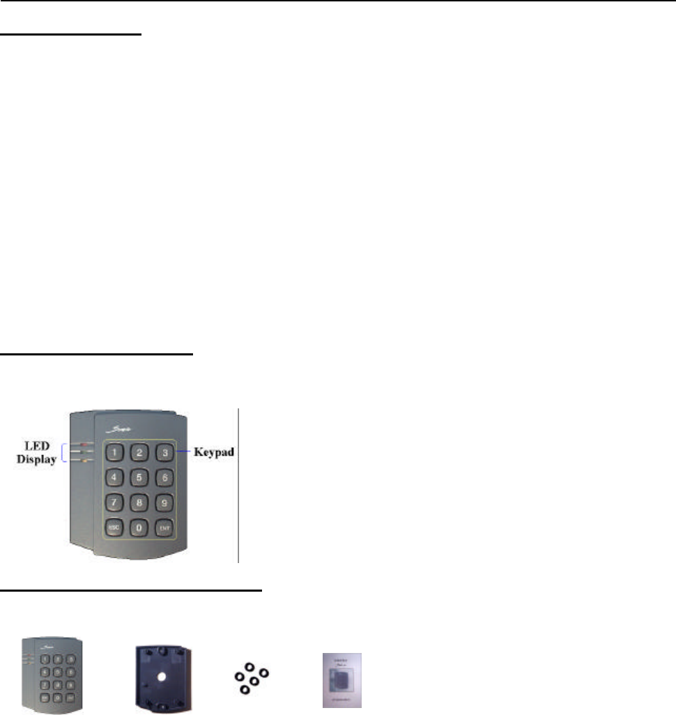
5. Name of each part
SDC1000
Main Unit
6. Identifying supplied parts
Please unpack and check the contents of the box.
Main Unit Wall Mount O-Ring Instructions
(1 EA) (1 EA) (5 EA) (1 EA)
MOTOROLA
SDC1000
SINGLE DOOR ACCESS CONTROLLER
- 5 -
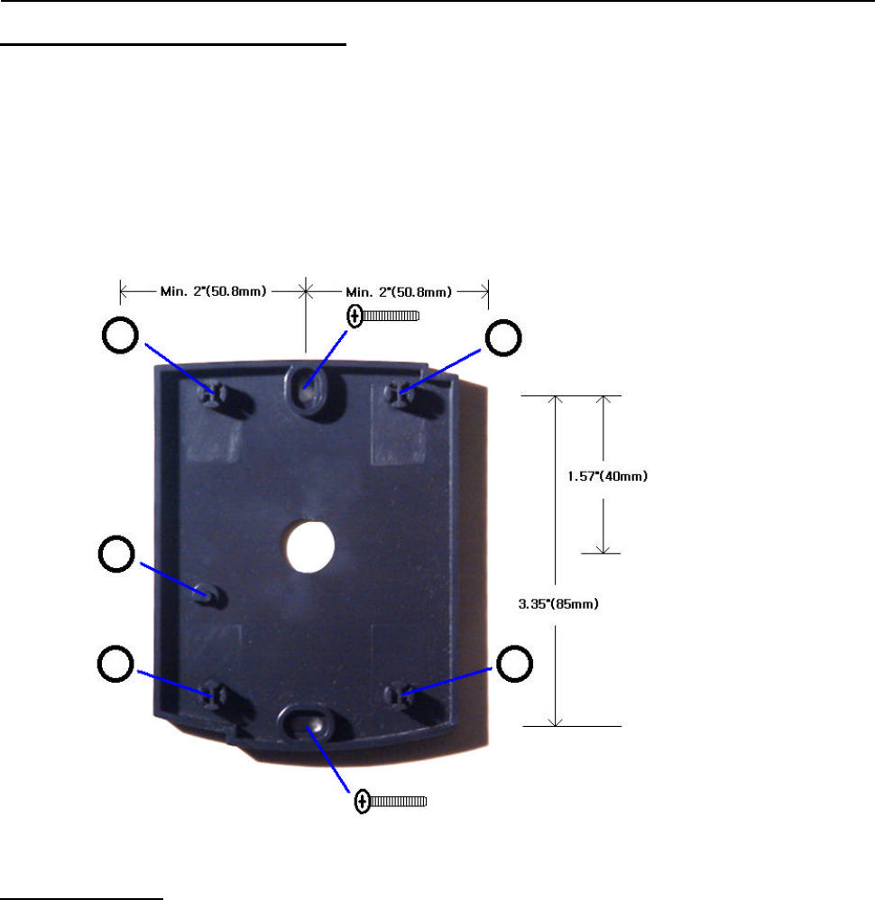
7. Installation of the Product
7-1. Drill two 6-32 holes and one 1/2" hole on the proper location of the wall.
(If the gang box is already installed on the wall then skip this step.)
7-2. Using 2 screws, install wall mount to the wall.
7-3. Insert 5 O-rings to the wall mount as indicated, then route the cable of the main
unit through the center hole and push the main unit to wall mount to lock the main
unit and make sure that the main unit is locked with wall mount.
* CAUTIONS *
When the main unit is once fixed to wall mount, the locking pins will tighten the main unit
therefore the operation test of the main unit should be required prior to fix the main unit to
wall mount. If the main unit has to be disassembled from the wall mount, then you need another
wall mount to be replaced as the locking pins of wall mount will be broken when the main unit
detached from the wall mount.

MOTOROLA
SDC1000
SINGLE DOOR ACCESS CONTROLLER
- 6 -
8. Wire Color Table of the Main Unit
POWER
Power(DC 12V) +12V Red wire, Red with White stripe
Power(DC 12V) 0V(GND) Black wire, Black with White stripe
OUTPUT
Door RELAY(2A) COM Gray wire with Red stripe
Door RELAY(2A) NC Blue wire with White stripe
Door RELAY(2A) NO White wire with Red stripe
Alarm RELAY(2A) COM White wire
Alarm RELAY(2A) NC Purple wire with White stripe
Alarm RELAY(2A) NO Purple wire
TTL Output TTL Orange wire with White stripe
CHIME BELL Output BELL Brown wire with White stripe
INPUT
Exit Button EXIT Yellow wire with Red stripe
Door Sensor CONTACT Green wire
External Input #1 IN#1 Orange wire
External Input #2 IN#2 Green wire with White stripe
External Input #3 IN#3 Brown wire
Extra Reader Input DATA0 Pink wire
Extra Reader Input DATA1 Cyan wire
RS232C INTERFACE
RS232-TX TXD Grey wire
RS232-RX RXD Blue wire
RS232-GND GND Yellow wire
MOTOROLA
SDC1000
SINGLE DOOR ACCESS CONTROLLER
- 7 -
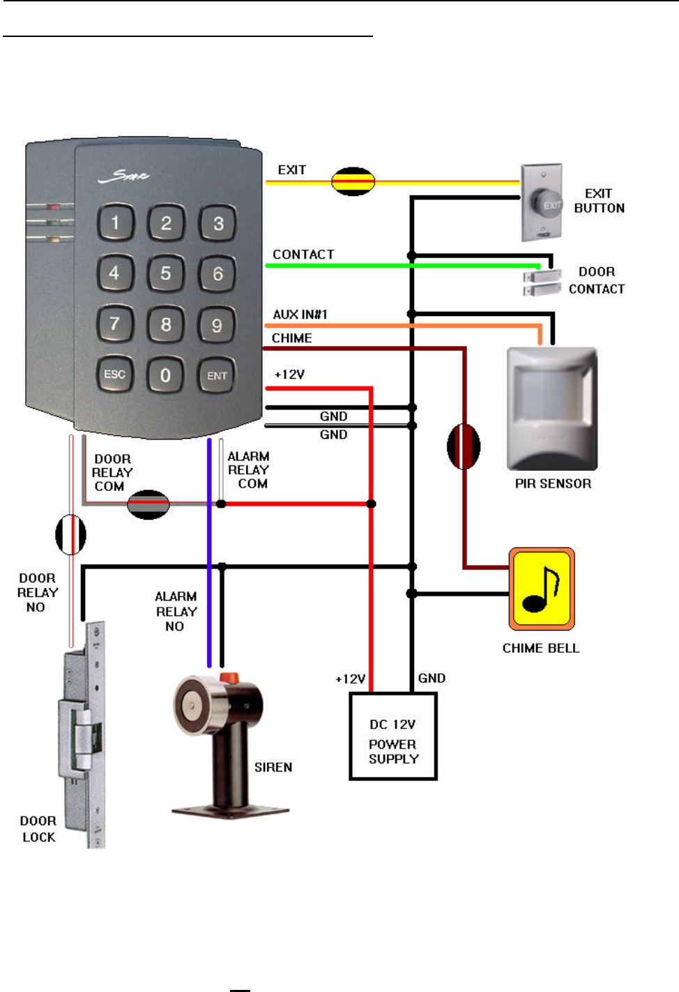
9. Wire connection for basic application
This connection can be changed for different applications.

MOTOROLA
SDC1000
SINGLE DOOR ACCESS CONTROLLER
- 8 -
9-1. Power Connection
Connect (+)wire of DC 12V power to Red wire and Red/White stripe wire and
connect Power GND(-)wire of DC 12V to Black wire and Black/White stripe wire.
9-2. Door Lock connection
9-2-1 Connection of POWER FAIL SAFE: Door Lock
- Connect Door RELAY(COM),Grey/Red stripe wire to DC +12V.
- Connect (+)wire of Door Lock to Door RELAY(NC),Blue/White stripe wire.
- Connect (-)wire of Door Lock to Power GND(-) wire.
9-2-2 Connection of POWER FAIL SECURE Door Lock
- Connect Door RELAY(COM),Grey/Red stripe wire to DC +12V.
- Connect (+)wire of Door Lock to Door RELAY(NO),White/Red stripe wire.
- Connect (-)wire of Door Lock to Power GND(-) wire.
9-3. Alarm Device connection
- Connect Alarm RELAY(COM),white wire to DC +12V.
- Connect (+)wire of Alarm Device to Alarm RELAY(NO),Purple wire.
- Connect (-)wire of Alarm Device to Power GND(-) wire.
9-4. Exit Button connection
- Connect one of the wire of Exit Button to Exit Button Input, Yellow/Red stripe wire.
- Connect the other wire of Exit Button to Power GND(-) wire.
(In case of using Normal Closing Contact for Exit Button then please make setting
change of ACTIVE level of Exit Button in section 8-20)
9-5. Door Contact sensor connection
- Connect Door Contact sensor(COM) wire to Door Contact Input, Green wire.
- Connect Door Contact sensor(NO) wire to Power GND(-) wire.
(In case of using Normal Closing(NC) Contact for Door Contact sensor then
please make setting change of ACTIVE level of Door Contact in section 8-21)
9-6. Auxiliary Input Device connection(Applied to AUX Input#1,#2,#3)
- Connect one wire of Auxiliary Input Device to AUX Input wire
(Input#1 Orange, Input#2 Green/White stripe, Input#3 Brown wire).
- Connect the other wire of Auxiliary Input Device to Power GND(-) wire.
(In case of using Normal Closing(NC) Contact for Auxiliary Input Device then
please make setting change of ACTIVE level of AUX Input in section 8-17 ~ 8-19)

MOTOROLA
SDC1000
SINGLE DOOR ACCESS CONTROLLER
- 9 -
9-7. Auto-dialer connection(Extra Purchase, If Necessary)
- Connect the input wire of Auto-dialer to TTL output, Orange/White stripe wire.
- Connect (+)wire of Auto-dialer to DC +12V.
- Connect (-)wire of Auto-dialer to Power GND(-) wire.
- Connect Telephone Line plug(RJ-14) to Auto-dialer.
(In case of using Low ACTIVE for Auto-dialer then
please make setting change of ACTIVE level of TTL Output in section 8-22)
9-8. RS232C Communication port Connection
9-pin connector(COM Port, female) is required to connect Serial communication
(RS232C) between Main Unit to Personal Computer.
Purchase 9-pin Female Connector, then connect wires as follow.
- Connect RS232-TX, Grey wire of Main Unit to pin number 2 of 9-pin connector.
- Connect RS232-RX, Blue wire of Main Unit to pin number 3 of 9-pin connector.
- Connect RS232-GND, Yellow wire of Main Unit to pin number 5 of 9-pin connector.
- Plug in 9-pin connector to COM1 or COM2 Port of Personal Computer.
- Install and run SDC1000 Time & Attendance Software.
9-9. Chime Bell Unit connection(Extra Purchase, If Necessary)
- Connect Red(+) wire of Chime Bell Unit to Bell Output, Brown/White wire of Main Unit.
- Connect Black(-) wire of Chime Bell Unit to Power GND(-) wire.
9-10. Extra Proximity Reader connection(Extra Purchase, If Necessary)
- Connect (+)wire of Reader to DC +12V.
- Connect (-)wire of Reader to Power GND(-) wire.
- Connect Wiegand output DATA0 of Reader to Pink wire
- Connect Wiegand output DATA1 of Reader to Cyan wire.
MOTOROLA
SDC1000
SINGLE DOOR ACCESS CONTROLLER
- 10 -
10. Initial Setup
Main Unit has Flash Memory to retain all setting values and when it delivered to customer there is no
data in the memory therefore Initial Setup is required for the first use.
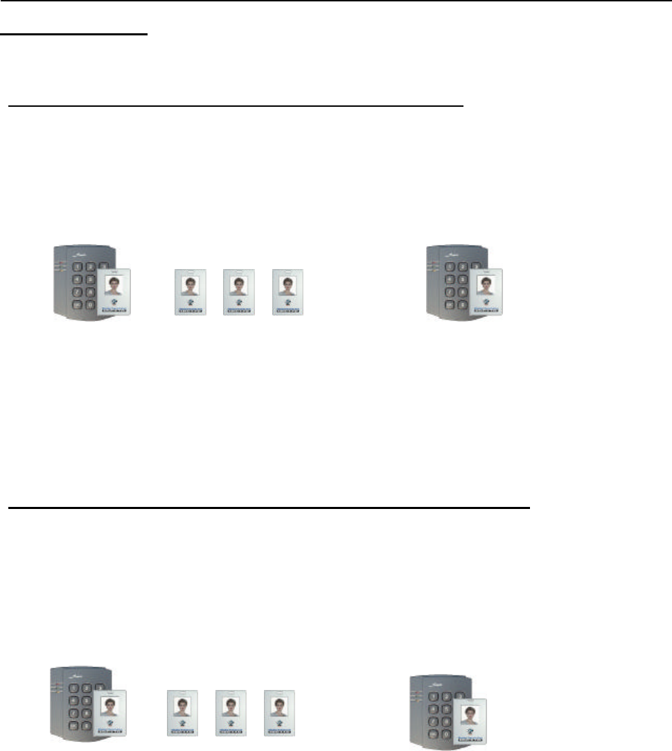
10-1. Registration of RF Cards for RF CARD ONLY MODE
* This mode is only applicable when the extra proximity reader is connected.
¨ç Turn switch on DC12V Power Supply.
All 3 LEDs will be flashing with starting sound.
¨è Press 0 1 ENT from the keypad.(RF CARD ONLY MODE )
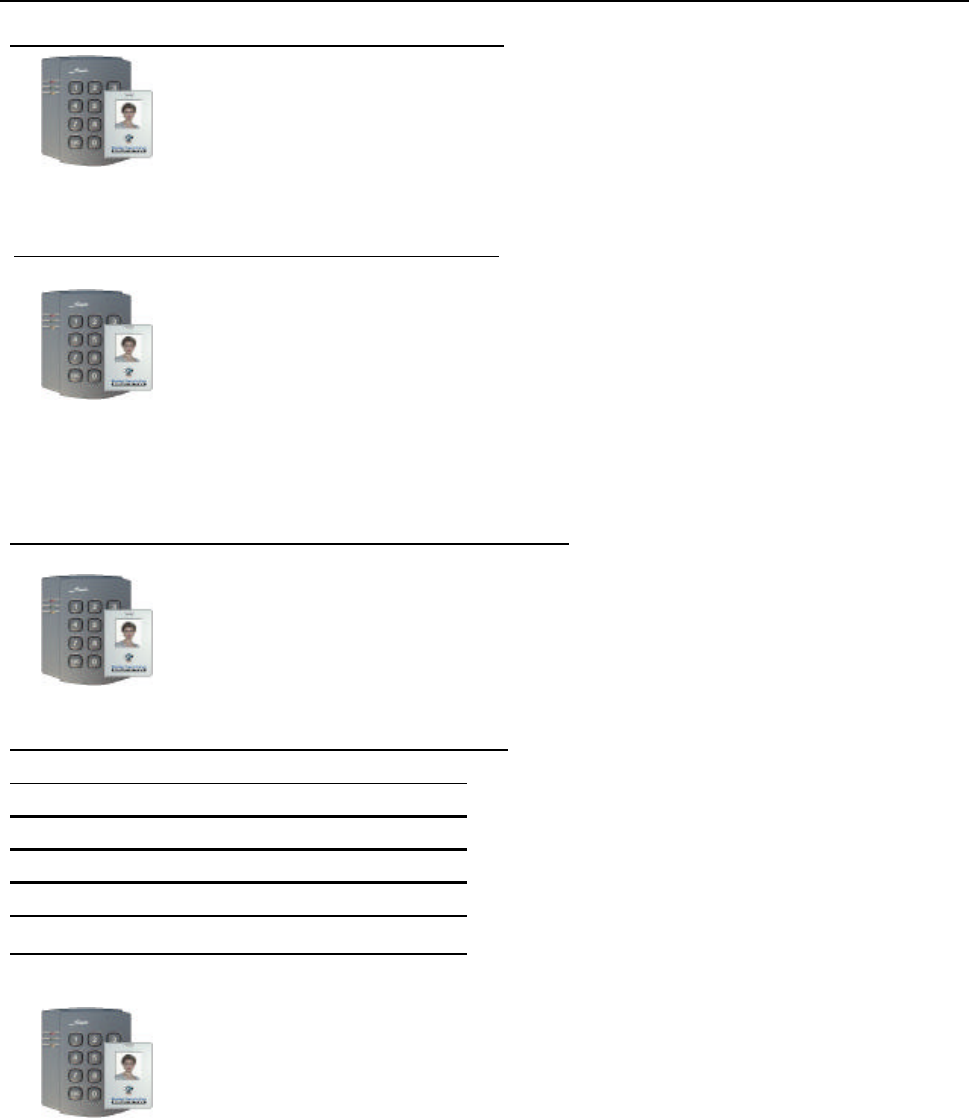
¨é Present RF Cards as follow to register Master Card and User Access Cards.
........
Master Card User Access Cards Master Card(Finish setup)
¨ê First read card is registered as Master Card and the RF Cards followed to Master
Card are registered as User Access Cards then present Master Card again to finish
setup. (Please keep Master Card at the secure location for further setting changes.)
¨ë Now, the Main Unit is entered to normal operation mode with default setting.
10-2. Registration of RF Cards with PIN for RF CARD + PIN MODE
* This mode is only applicable when the extra proximity reader is connected.
¨ç Turn switch on DC12V Power Supply.
All 3 LEDs will be flashing with starting sound.
¨è Press 0 2 ENT from the keypad.(RF CARD + PIN MODE )
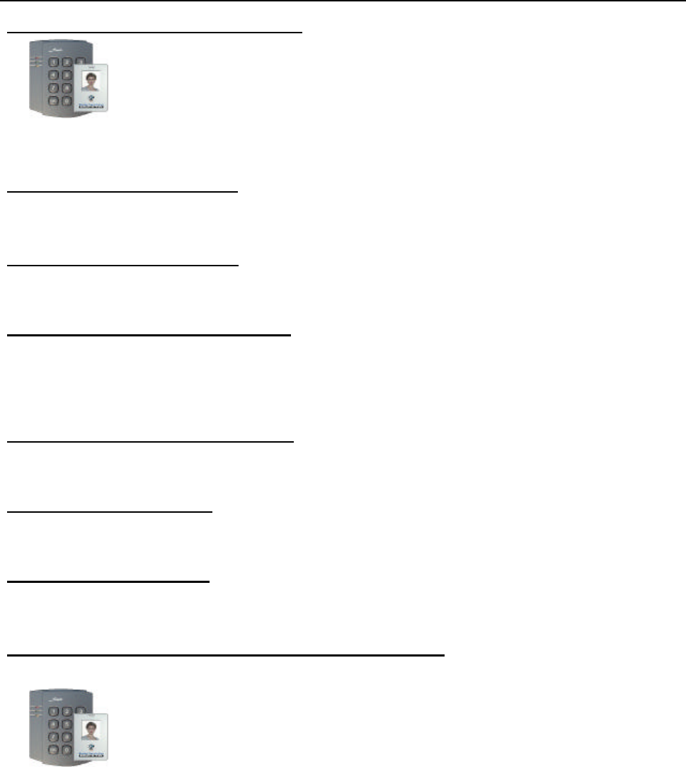
¨é Present RF Cards as follow to register Master Card and User Access Cards and type
4~6 digits Personal Identification Number(PIN) followed by each User Access Card.
........
Master Card User Access Cards+PINENT Master Card(Finish setup)
¨ê First read card is registered as Master Card and the RF Cards+PINENT followed
to Master Card are registered as User Access Cards with PIN numbers then present
Master Card again to finish setup.
(Please keep Master Card at the secure location for further setting changes.)

MOTOROLA
SDC1000
SINGLE DOOR ACCESS CONTROLLER
- 11 -
¨ë Now, the Main Unit is entered to normal operation mode with default setting.
10-3. Registration of PIN ONLY MODE
¨ç Turn switch on DC12V Power Supply.
All 3 LEDs will be flashing with starting sound.
¨è Press 0 3 ENT from the keypad.(PIN ONLY MODE )
¨é Enter a 8 digits PIN number + ENT to register Master PIN number then type 4~6
digits PIN number + ENT to register User Access PIN numbers then type 8 digits
Master PIN number to finish setup.
8digits PINENT 4~6digits PINENT ... 8digits Master PINENT
Master PIN User Access PIN ... Master PIN(Finish setup)
¨ê First 8 digits PIN number is registered as Master PIN and 4~6 digits PIN followed
to Master PIN are registered as User Access PIN numbers then type Master PIN
again to finish setup.
(Please write and remember Master PIN number for further setting changes.)
¨ë Now, the Main Unit is entered to normal operation mode with default setting.
10-4. Default Setting Values
After the Initial Setup, the Main Unit stores its default setting values as follows and run
normal operation mode. If you want to change the setting values, add or delete USER
Access Cards(or PIN) then please refer to "Setting Changes" in section 8.
¨ç When User Access Card(or PIN) is granted
- Door RELAY activates for 3sec.
- Green LED lights on for 3sec.
¨è When User Access Card(or PIN) is denied
- Alarm RELAY activates for 2sec.
- Red LED lights on for 2sec.
MOTOROLA
SDC1000
SINGLE DOOR ACCESS CONTROLLER
- 12 -
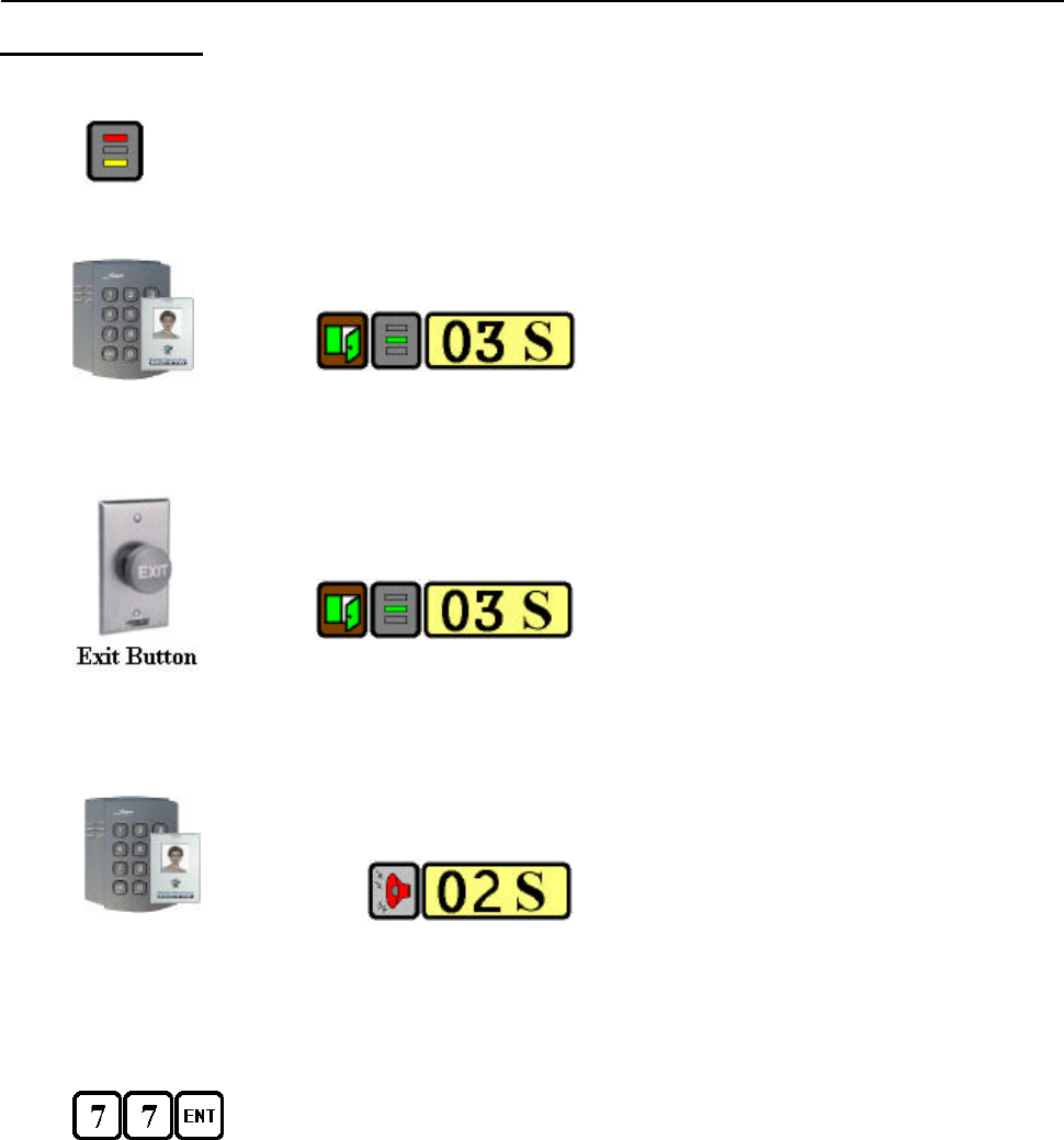
11. Operation
11-1. Normal Operation Mode(Safe Mode)
When the Main Unit is running in normal operation mode,
Yellow LED is flashing every second.
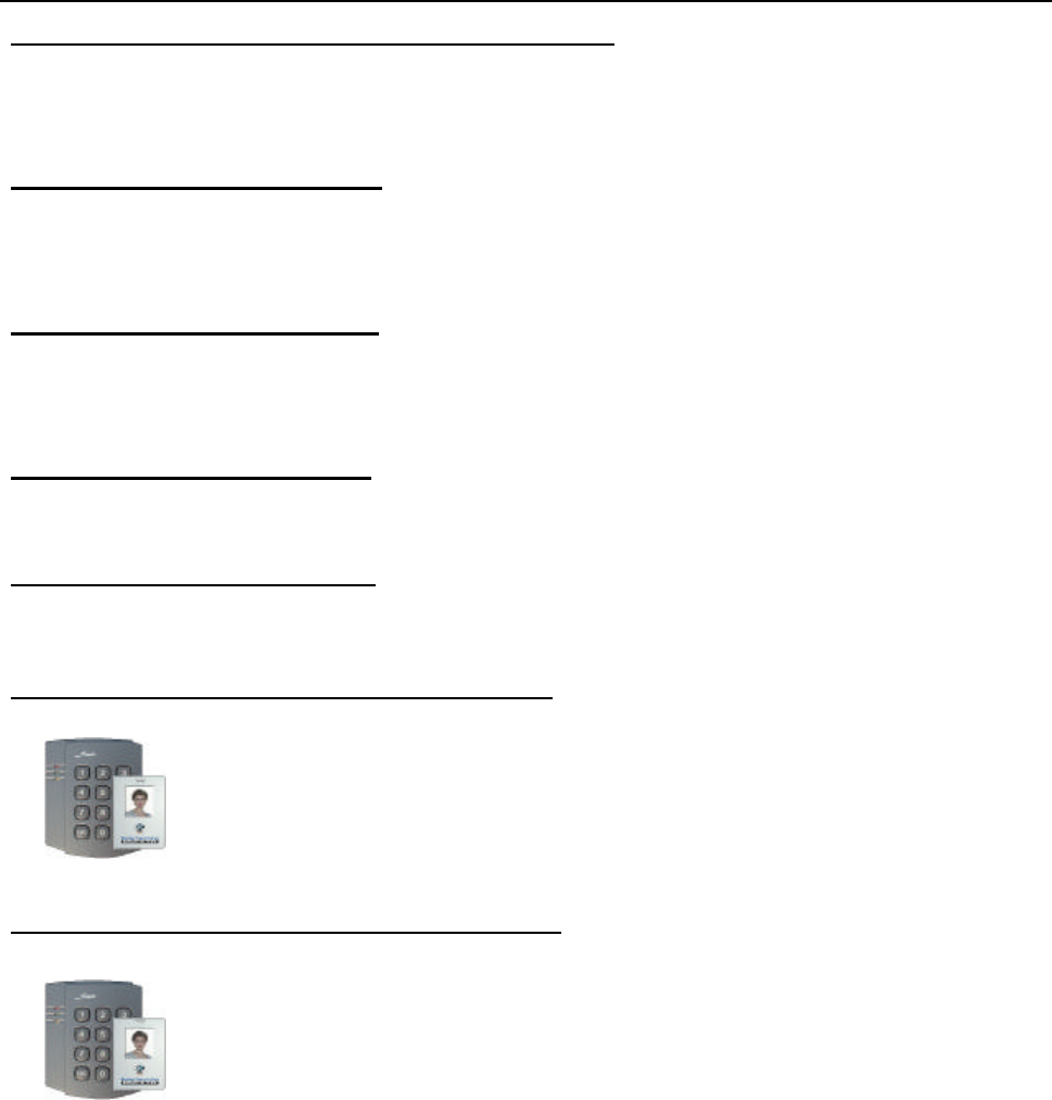
11-2. Open the Door
User Access Card(or PIN) is granted, Door opens for 3 seconds
with "do-mi-sol-do" melody.
Registered card(or PIN)
11-3. Exit(Open the Door)
To exit, press Exit Button and Door opens for 3 seconds.
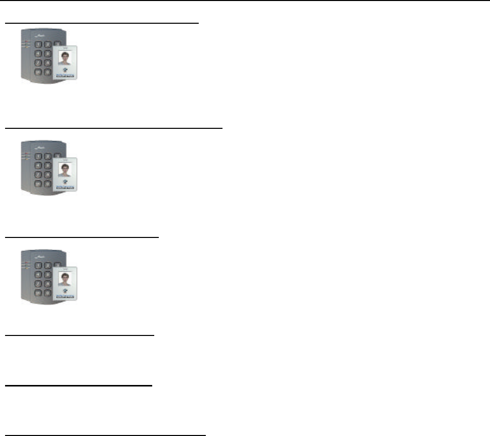
11-4. Alarm by Unregistered Card(or PIN)
User Access Card(or PIN) is not registered and access is denied,
then Alarm RELAY activates for 2 sec. with "sol-do-sol-do" melody.
Unregistered card(or PIN)
(If you do not want to activate Alarm, then please change settings in section 8-22.)
11-5. Secure Mode
Last exit person can change the mode from Safe Mode to Secure Mode by pressing.
Secure Code from the keypad so that the Alarm will generate by AUX Inputs.
-> Change to Secure Mode.
It will canceled automatically when the registered card(or PIN) is present.
11-6. DURESS Alarm
In case of opening the door by Duress condition, press Duress PassWordENT and
open the door as usual then Duress Alarm(TTL Output) will activate.

MOTOROLA
SDC1000
SINGLE DOOR ACCESS CONTROLLER
- 13 -
11-7. Chime Bell operation
When the guest presses ESC(Bell) Button from the keypad, Chime Bell melody is
activating for 5 seconds.
12. Setting Changes
To change previous setting values, you need Master Card(or PIN) to get in to Setting Change mode.
First present Master Card(or press Master PIN) and enter 2-digit command code.
Present Master Card(or PIN) and press 2digit command code.
+ Command code +
Command Change setting values
11 Add User Access Cards(RF CARD ONLY MODE)
12 Add User Access Cards and PIN(RF CARD + PIN MODE)
13 Add User Access PIN numbers(PIN ONLY MODE)
14 Delete User Access Cards(or PIN)
21 Change Door open time when User Access Card(or PIN) is granted
22 Change Alarm time when User Access Card(or PIN) is denied
23 Change Alarm time when Try Our error detected
24 Change Alarm time when Door Contact error detected
25 Change Alarm time when AUX#1 Input detected
26 Change Alarm time when AUX#2 Input detected
27 Change Alarm time when AUX#3 Input detected
28 Change Alarm time when magnet detected
29 Register 2 digits Duress Alarm Code
30 Change Alarm time when Duress Alarm detected
31 Test Door open time set by command "21"
32 Test Alarm time set by command "22"
33 Test Alarm time set by command "23"
34 Test Alarm time set by command "24"
35 Test Alarm time set by command "25"
36 Test Alarm time set by command "26"
37 Test Alarm time set by command "27"
39 Change Chime Bell activating time

MOTOROLA
SDC1000
SINGLE DOOR ACCESS CONTROLLER
- 14 -
Command Change setting values
41 Unconditional Door Open
42 Unconditional Door Close
43 Enable QUICK ACCESS MODE(Operate only PIN MODE)
44 Disable QUICK ACCESS MODE(Operate only PIN MODE)
51 Disable Melody sound
52 Enable Melody sound
60 Change keypad lock time when Try Out error detected
61 Detect AUX#1 Input from 'L' to ‘H'
62 Detect AUX#1 Input from 'H' to ‘L'
63 Detect AUX#2 Input from 'L' to ‘H'
64 Detect AUX#2 Input from 'H' to ‘L'
65 Detect AUX#3 Input from 'L' to ‘H'
66 Detect AUX#3 Input from 'H' to ‘L'
67 Detect Exit Button Input from 'L' to 'H'
68 Detect Exit Button Input from 'H' to 'L'
69 Detect Door Contact sensor Input from 'L' to 'H'
70 Detect Door Contact sensor Input from 'H' to 'L'
71 Activate TTL output to ‘H'
72 Activate TTL output to ‘L'
77 Enable Chime Bell Output
78 Disable Chime Bell Output
80 Set delay time to activate SECURE MODE
81 Set watch-dog time for Door Contact sensor
82 Set number of times of Try-Out
83 Set input limit time from the keypad
84 Set Temper Alarm port
88 Enable Temper Alarm
89 Disable temper Alarm
99 Initialize and erase all setup data
MOTOROLA
SDC1000
SINGLE DOOR ACCESS CONTROLLER
- 15 -
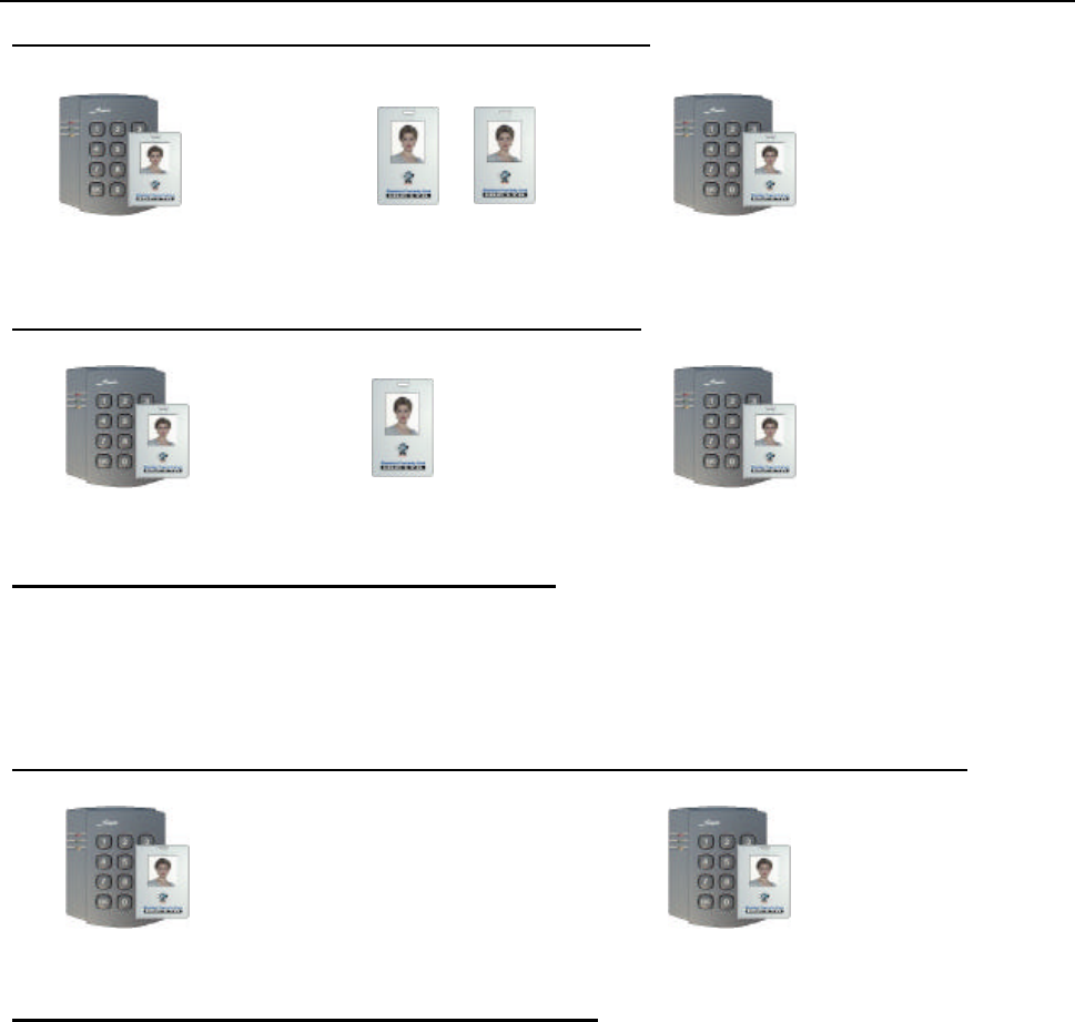
12-11. Add User Access Cards(RF CARD ONLY MODE)
11ENT .....
Master card Command Cards to be registered .... Master card
12-12. Add User Access Cards(RF CARD + PIN MODE)
12ENT PINENT .....
Master card Command Cards to be registered .... Master card
12-13. Add User Access PIN(PIN ONLY MODE)
MasterPINENT 13ENT PINENT ..... MasterPINENT
Master PIN Command PIN to be registered .... Master PIN
12-14.1. Delete User Access Cards(RF CARD ONLY MODE, RF CARD+PIN MODE)
14ENT CardNumberENT .....
Master Card Command Cards to be deleted .... Master Card
12-14.2. Delete User Access PIN(PIN ONLY MODE)
MasterPINENT 14ENT PINENT ..... MasterPINENT
Master PIN Command PIN to be deleted .... Master PIN

MOTOROLA
SDC1000
SINGLE DOOR ACCESS CONTROLLER
- 16 -
<Table 1> Settings for command 21~28
Symbol Setting Values Examples/Remarks
Output
Mode
OM
(You must add value ¨ç and ¨è)
Setting value for activating time
¨ç Activate Time Value
Activate only Secure Mode : 00
Activate all the time : 50
____________________________________________
Setting Value for activate Output Port
¨è Activate Output Port Value
Activate only Door Relay : 01
Activate only Alarm Relay : 02
Activate only TTL Output : 04
Activate Door Relay & TTL : 05
Activate Alarm Relay & TTL : 06
EX1)Activate Door Relay
all the time
Door RELAY 01
All the time 50
OM = 51
EX2)Activate Alarm Relay
and TTL during the
Secure mode
Alarm+TTL 06
Secure Mode 00
OM = 06
tt tt is the activating time value(seconds)
from 01sec. to 99sec. tt value 00sec. means
no operation.
PW PW is the 2 digits PassWord for
Duress Alarm. Do not use
‘
77
’
as it Is
used for Secure Mode
mm mm is activating time value(minutes)
from 01min. to 99min. mm value 00min. means
no operation.
MOTOROLA
SDC1000
SINGLE DOOR ACCESS CONTROLLER
- 17 -
12-21. Change Door open time when User Access Card(or PIN) is granted
(Please refer to Table 1 for tt)
21ENT ttENT ttENT
Master card or Command Door time TTL time
MasterPINENT
12-22. Change Alarm time when User Access Card(or PIN) is denied
(Please refer to Table 1 for OM, tt)
22ENT OMENT ttENT ttENT ttENT
Master card or Command Output Mode Door time Alarm Time TTL time
MasterPINENT
12-23. Change Alarm time when Try Our error detected
(Please refer to Table 1 for OM, tt)
23ENT OMENT ttENT ttENT ttENT
Master card or Command Output Mode Door Time Alarm Time TTL Time
MasterPINENT
12-24. Change Alarm time when Door Contact error detected
(Please refer to Table 1 for OM, tt)
24ENT OMENT ttENT ttENT ttENT
Master card or Command Output Mode Door Time Alarm Time TTL Time
MasterPINENT
12-25. Change Alarm time when AUX#1 Input detected
12-26. Change Alarm time when AUX#2 Input detected
12-27. Change Alarm time when AUX#3 Input detected
(Please refer to Table 1 for OM, tt)
25ENT
26ENT OMENT ttENT ttENT ttENT
27ENT
Master card or Command Output Mode Door Time Alarm Time TTL Time
MasterPINENT
MOTOROLA
SDC1000
SINGLE DOOR ACCESS CONTROLLER
- 18 -
12-28. Change Alarm time when magnet detected
(Please refer to Table 1 for OM, tt)
28ENT OMENT ttENT ttENT ttENT
Master card or Command Output Mode Door Time Alarm Time TTL Time
MasterPINENT
12-29. Register 2 digits Duress Alarm PassWord
(Please refer to Table 1 for PW)
29ENT PW
Master card or Command PassWord
MasterPINENT
* ‘00’ is registered as default PassWord.
12-30. Change Alarm time when Duress Alarm detected
(Please refer to Table 1 for OM, tt)
30ENT OMENT ttENT ttENT ttENT
Master card or Command Output Mode Door Time Alarm Time TTL Time
MasterPINENT
12-31. Test Door open time set by command "21"
12-32. Test Alarm time set by command "22"
12-33. Test Alarm time set by command "23"
12-34. Test Alarm time set by command "24"
12-35. Test Alarm time set by command "25"
12-36. Test Alarm time set by command "26"
12-37. Test Alarm time set by command "27"
Outputs set by command will be tested.
31~37ENT
Master card or Command
MasterPINENT
MOTOROLA
SDC1000
SINGLE DOOR ACCESS CONTROLLER
- 19 -
12-39. Change Chime Bell activating time
(Please refer to Table 1 for tt)
39ENT ttENT
Master card or Command Chime Bell Time
MasterPINENT
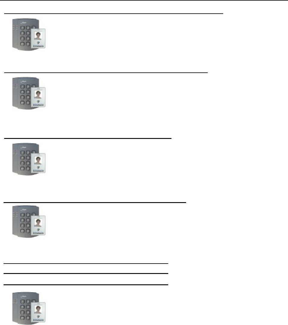
12-41. Unconditional Door Open
Master card or 41ENT
MasterPINENT
12-42. Unconditional Door Close
Master card or 42ENT
MasterPINENT
12-43. Enable QUICK ACCESS MODE
When QUICK ACCESS MODE is enabled in PIN ONLY MODE,
Door will open just press ENT key.
Master card or 43ENT
MasterPINENT
12-44. Disable QUICK ACCESS MODE
Master card or 44ENT
MasterPINENT
12-51. Disable Melody sound
Master card or 51ENT
MasterPINENT
12-52. Enable Melody sound
Master card or 52ENT
MasterPINENT
12-60. Change keypad lock time when Try Out error detected
(Please refer to Table 1 for tt)
60ENT ttENT
Master card or Command Keypad Lock Time
MasterPINENT

MOTOROLA
SDC1000
SINGLE DOOR ACCESS CONTROLLER
- 20 -
12-61. Detect AUX#1 Input from 'L' to ‘H'
AUX#1 input is detected on the raising edge of AUX#1 input
Master card or 61ENT
MasterPINENT
12-62. Detect AUX#1 Input from 'H' to ‘L'
AUX#1 input is detected on the falling edge of AUX#1 input
Master card or 62ENT
MasterPINENT
12-63. Detect AUX#2 Input from 'L' to ‘H'
AUX#2 input is detected on the raising edge of AUX#2 input
Master card or 63ENT
MasterPINENT
12-64. Detect AUX#2 Input from 'H' to ‘L'
AUX#2 input is detected on the falling edge of AUX#2 input
Master card or 64ENT
MasterPINENT
12-65. Detect AUX#3 Input from 'L' to ‘H'
AUX#3 input is detected on the raising edge of AUX#3 input
Master card or 65ENT
MasterPINENT
12-66. Detect AUX#3 Input from 'H' to ‘L'
AUX#3 input is detected on the falling edge of AUX#3 input
Master card or 66ENT
MasterPINENT
12-67. Detect Exit Button Input from 'L' to 'H'
Exit Button input is detected on the raising edge of Exit Button input
Master card or 67ENT
MasterPINENT
12-68. Detect Exit Button Input from 'H' to 'L'
Exit Button input is detected on the falling edge of Exit Button input
Master card or 68ENT
MasterPINENT
12-69. Detect Door Contact sensor Input from 'L' to 'H'
Door Contact input is detected on the raising edge of Door Contact input
Master card or 69ENT
MasterPINENT
MOTOROLA
SDC1000
SINGLE DOOR ACCESS CONTROLLER
- 21 -
12-70. Detect Door Contact sensor Input from 'H' to 'L'
Door Contact input is detected on the falling edge of Door Contact input
Master card or 70ENT
MasterPINENT
12-71. Activate TTL output to ‘H'
TTL output changes the state from logic '0' to logic '1' when it activates.
Master card or 71ENT
MasterPINENT
12-72. Activate TTL output to ‘L'
TTL output changes the state from logic '1' to logic '0' when it activates.
Master card or 72ENT
MasterPINENT
12-77. Enable Chime Bell Output
Master card or 77ENT
MasterPINENT
12-78. Disable Chime Bell Output
Master card or 78ENT
MasterPINENT
12-80. Set delay time to activate SECURE MODE
(Please refer to Table 1 for mm)
80ENT mmENT
Master card or Command Delay Time
MasterPINENT
12-81. Set watch-dog time for Door Contact sensor
(Please refer to Table 1 for tt)
81ENT ttENT
Master card or Command Watch-dog Time
MasterPINENT
MOTOROLA
SDC1000
SINGLE DOOR ACCESS CONTROLLER
- 22 -
12-82. Set number of times of Try-Out
NN is the Try-out numbers from 00 to 99 times.
82ENT NNENT
Master card or Command Try-out Numbers
MasterPINENT
12-83. Set input limit time from the keypad
(Please refer to Table 1 for tt from 10 ~ 99)
83ENT ttENT
Master card or Command Input Limit Time
MasterPINENT
12-84. Set Temper Alarm port
(Please refer to Table 1 for OM)
84ENT OMENT
Master card or Command Alarm Port
MasterPINENT
12-88. Enable Temper Alarm
Master card or 88ENT
MasterPINENT
12-89. Disable temper Alarm
Master card or 89ENT
MasterPINENT
12-99. Initialize and erase all setup data
Please use this command when you really want to erase all data and start
the unit from the begining.
Master card or 99ENT
MasterPINENT

MOTOROLA
SDC1000
SINGLE DOOR ACCESS CONTROLLER
- 23 -
13. FCC REGISTRATION INFORMATION
FCC REQUIREMENTS PART 15
Caution: Any changes or modifications in construction of this device which are not expressly approved by the responsible
for compliance cold void the user's authority to operate the equipment.
NOTE: This device complies with Part 15 of the FCC Rules.
Operation is subject to the following two conditions;
1. This device may not cause harmful interface, and
2. This device must accept any interference received, including interference that may cause undesired
operation.
This equipment has been tested and found to comply with the limits for a Class A digital device, pursuant to part 15
of the FCC Rules. These limits are designed to provide reasonable protection against harmful interference when
the equipment is operated in a commercial environment. This equipment generates, uses, and can radiate radio
frequency energy and, if not installed and used in accordance with the instruction manual, may cause harmful
interference to radio communications. Operation of this equipment in a residential area is likely to cause harmful
interference in which case the user will be required to correct the interference at his own expense.

MOTOROLA
SDC1000
SINGLE DOOR ACCESS CONTROLLER
- 24 -
14. Warranty and Service
The following warranty and service information applies only to the United States of America and Republic of Korea. For
the information in other countries, please contact your local distributor.
To obtain in or out of warranty service, please prepay shipment and return the unit to the appropriate facility listed below.
IN THE UNITED STATES
RF LOGICS Inc. Service Center
3026 Scott Blvd.,
SANTA CLARA, CA95054 USA
Tel.: (408) 980-0001
Fax.: (408) 980-8060
E-mail: rflogics@rflogics.com
Web-site: www.rflogics.com
OUTSIDE OF THE UNITED STATES
ID TECK CO., LTD. Service Center
5F Ace Techno Tower Bldg.,
684-1 Deungchon-dong, Gangsuh-gu,
SEOUL 157-030, KOREA
Tel.: +82 (2) 659-0055
Fax.: +82 (2) 659-0086
E-mail: webmaster@idteck.com
Web-site: www.idteck.com
Please use the original container, or pack the unit(s) in a sturdy carton with sufficient packing to prevent damage, include
the following information:
1. A proof-of-purchase indicating model number and date of purchase.
2. Bill-to address
3. Ship-to address
4. Number and description of units shipped.
5. Name and telephone number of person to contact.
6. Reason for return and description of the problem.
NOTE: Damage occuring during shipment is deemed the responsibility of the carrier, and claims should be made directly to
the carrier.