HUNAN FN LINK TECHNOLOGY F11AMIM13-B1 WIFI Module User Manual
FN-LINK TECHNOLOGY LIMITED WIFI Module Users Manual
15_F11AMIM13-B1 UserMan,r1
Product Specification
IEEE 802.11 b/g/n 2.4GHz 1T1R WiFi Module
Project Name RTL8711AM IoT Module
Model NO F11AMIM13-B1
Customer
Customer’s Part NO
Approved: William Tan Checked: Jim Hu Drafted: Neal Yu
Feedback of customer’s Confirmation
We accept the specification after Confirmed.
Customer Customer signature Approved Date
FN-LINK TECHNOLOGY LIMITED
A Building,HuiXin industrial park,No 31,
YongHe road, Fuyong town, Bao'an
District,Shenzhen City, CHINA
TEL: 86-0755-29558186
FAX: 86-0755-29558196
Website: www.fn-link.com

FN-LINK TECHNOLOGY LIMITED
Page2/12
CONTENTS
0 REVESION HISTORY....................................................................................................................................3
1 INTRODUCTIONS.......................................................................................................................................... 4
1.1 OVERVEIW.............................................................................................................................................. 4
1.2 PRODUCT FEATURES..........................................................................................................................4
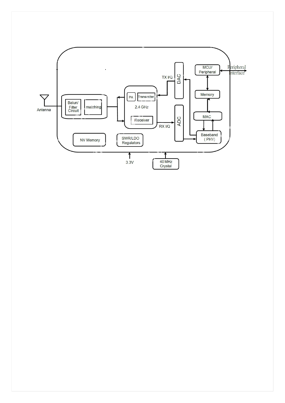
2 BLOCK DIAGRAM..........................................................................................................................................5
3 GENERAL SPECIFICATION.........................................................................................................................6
4 MECHANICAL AND ELECTRICAL SPECIFICATION.............................................................................. 7
4.1 OUTLINE DRAWING..............................................................................................................................7
4.2 PIN DEFINITION.....................................................................................................................................9
4.3 PCB LAY-OUT REFERENCE..............................................................................................................11
4.4 RECOMMENDED REFLOW PROFILE............................................................................................ 12
4.5 NOTICE.................................................................................................................................................. 12


FN-LINK TECHNOLOGY LIMITED
Page4/12
1. Introduction
1.1 Overview
F11AMIM13-B1 is a highly integrated module with low power 802.11n Wireless LAN(WLAN) network
controller. It combines an ARM-CM3 MCU, WLAN MAC, a 1T1R capable WLAN baseband, and RF
function. It also provides a bunch of configurable GPIOs which are configured as digital peripherals for
different applications and control usage.
F11AMIM13 integrates internal memories for complete WIFI protocol functions.
1.2 Product Features
General
24mm*18mm*1.6mm
CMOS MAC, Baseband PHY, and RF in the module for 802.11b/g/n compatible WLAN
Complete 802.11n solution for 2.4G band
150Mbps receive PHY rate and 150Mbps transmit PHY rate using 40MHz bandwidth
Standards Supported
802.11b/g/n compatible WLAN
802.11e QoS Enhancement(WMM)
802.11i(WPA,WP2). Open, shared key, and pair-wise key authentication services
WiFi Direct support
Light Weight TCP/IP protocol
WLAN PHY Features
802.11n OFDM
One Transmit and one Receive path(1T1R)
20MHz and 40MHz bandwidth transmission
Short Guard Interval(400ns)
Maximum data rate 54Mbps in 802.11g and 150Mbps in 802.11n
Host Interface
2 x UART
1x I2C
1x SPI
3x PWM
1x ADC
GPIO

FN-LINK TECHNOLOGY LIMITED
Page6/12
3. General specification
General features
Main Chipset Realtek RTL8711AM
Host Interface UART,I2C,SPI,PWM,ADC
WiFi Standards 802.11b/g/n
Other RF Standards None
Dimension L24.0mm*W18.0mm*H0.8mm
Operating conditions
Operating Voltage 3.3±10% Vdc
Operating Temperature 0°C to +70°C
Storage Temperature -40°C to +80°C
RF features
Operating Frequency 2.400~2.4835GHz
Channels
WiFi:
USA/Canada: channel 1~11;
Europe/China/Australia: channel 1~13;
Japan: channel 1~14
Modulation
WiFi:
802.11b(DSSS): CCK(11, 5.5Mbps), DQPSK(2Mbps), DBPSK(1Mbps);
802.11g(OFDM): BPSK(9,6Mbps), QPSK(18,12Mbps),
16QAM(36,24Mbps), 64QAM(54,48Mbps);
802.11n(OFDM): BPSK, QPSK, 16QAM, 64QAM(150Mbps)
PHY Data rates
WiFi:
802.11b: 11,5.5,2,1 Mbps
802.11g: 54,48,36,24,18,12,9,6 Mbps
802.11n: up to 150Mbps
Output Power
WiFi:
802.11b 16±2dBm
802.11g 14±2dBm
802.11n 13±2dBm
EVM
802.11b EVM≦35%
802.11g EVM≦-25dB
802.11n EVM≦-28dB
FN-LINK TECHNOLOGY LIMITED
Page7/12
Sensitivity
WiFi:
802.11b@8% PER
1Mbps -88dBm
2Mbps -87dBm
5.5Mbps -85dBm
11Mbps -82dBm
802.11g@10% PER
6Mbps -86dBm
9Mbps -85dBm
12Mbps -84dBm
18Mbps -82dBm
24Mbps -80dBm
36Mbps -77dBm
48Mbps -73dBm
54Mbps -71dBm
802.11n_HT20@10% PER
MCS 0 -83dBm
MCS 1 -82dBm
MCS 2 -80dBm
MCS 3 -78dBm
MCS 4 -75dBm
MCS 5 -71dBm
MCS 6 -69dBm
MCS 7 -67dBm
Other features
Antenna Internal Antenna
Network Architecture
WiFi:
Ad-hoc mode (Peer-to-Peer )
Infrastructure mode
WiFi Direct
Security 802.11i(WPA,WP2). Open, shared key, and pair-wise key
authentication services
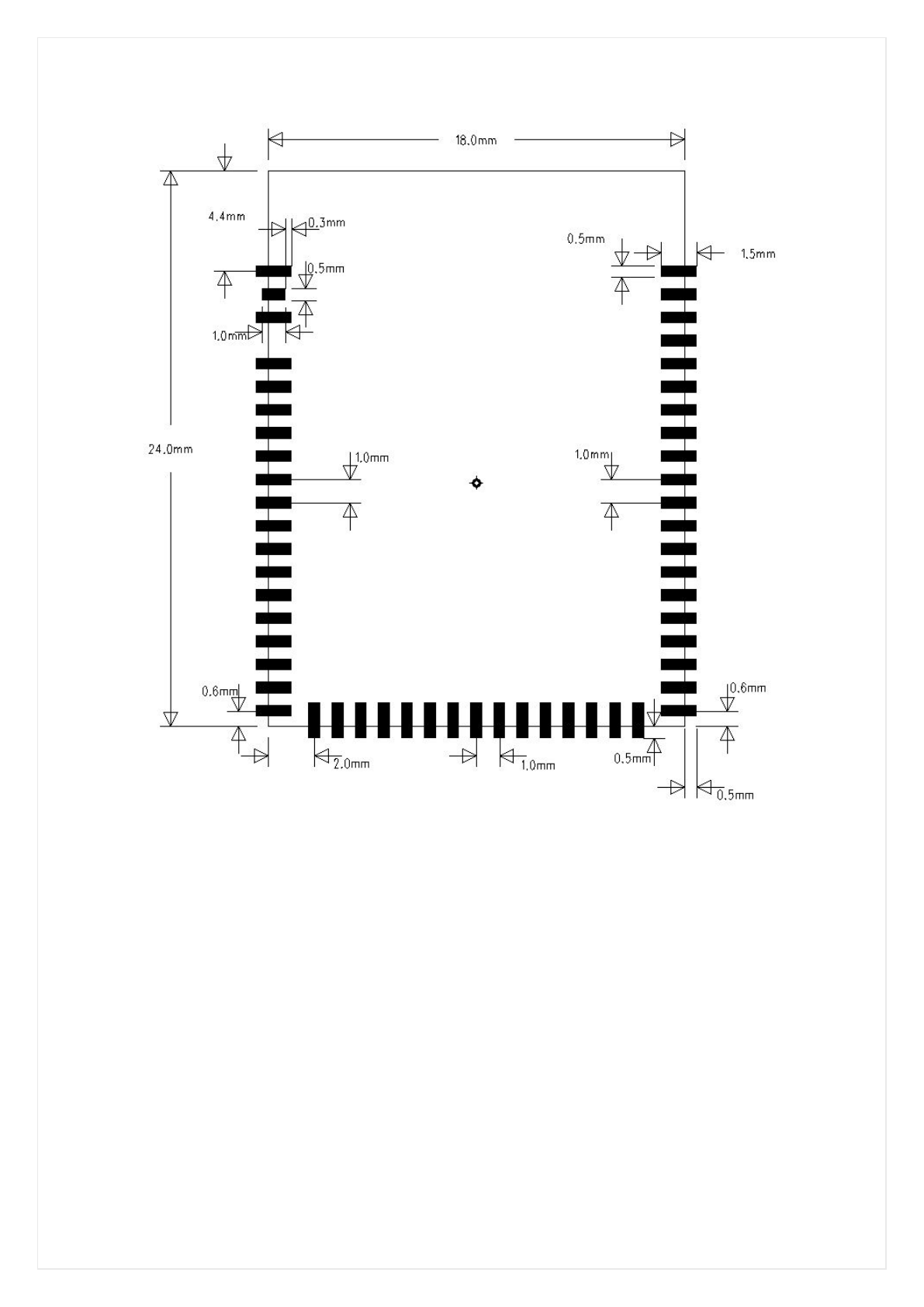
4. Mechanical and Electrical Specification
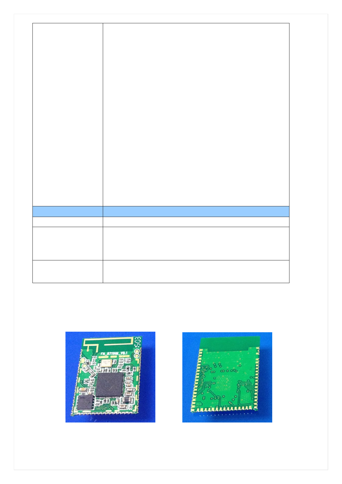
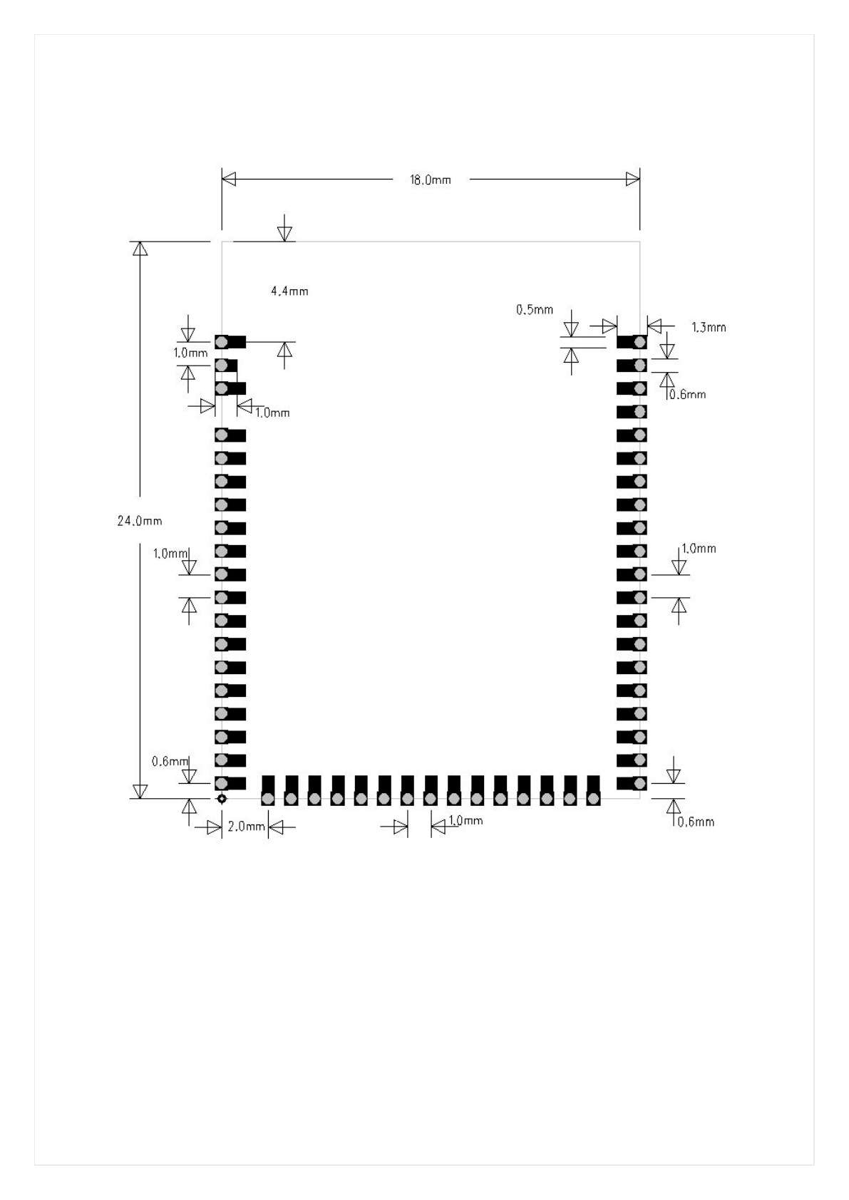
4.1 Outline Drawing(Unit: mm)
Top Side Bottom Side
Note:There Will be Changes in Layout ,But the Outline Will not Change,The Follow-up Will be Updated
FN-LINK TECHNOLOGY LIMITED
Page9/12
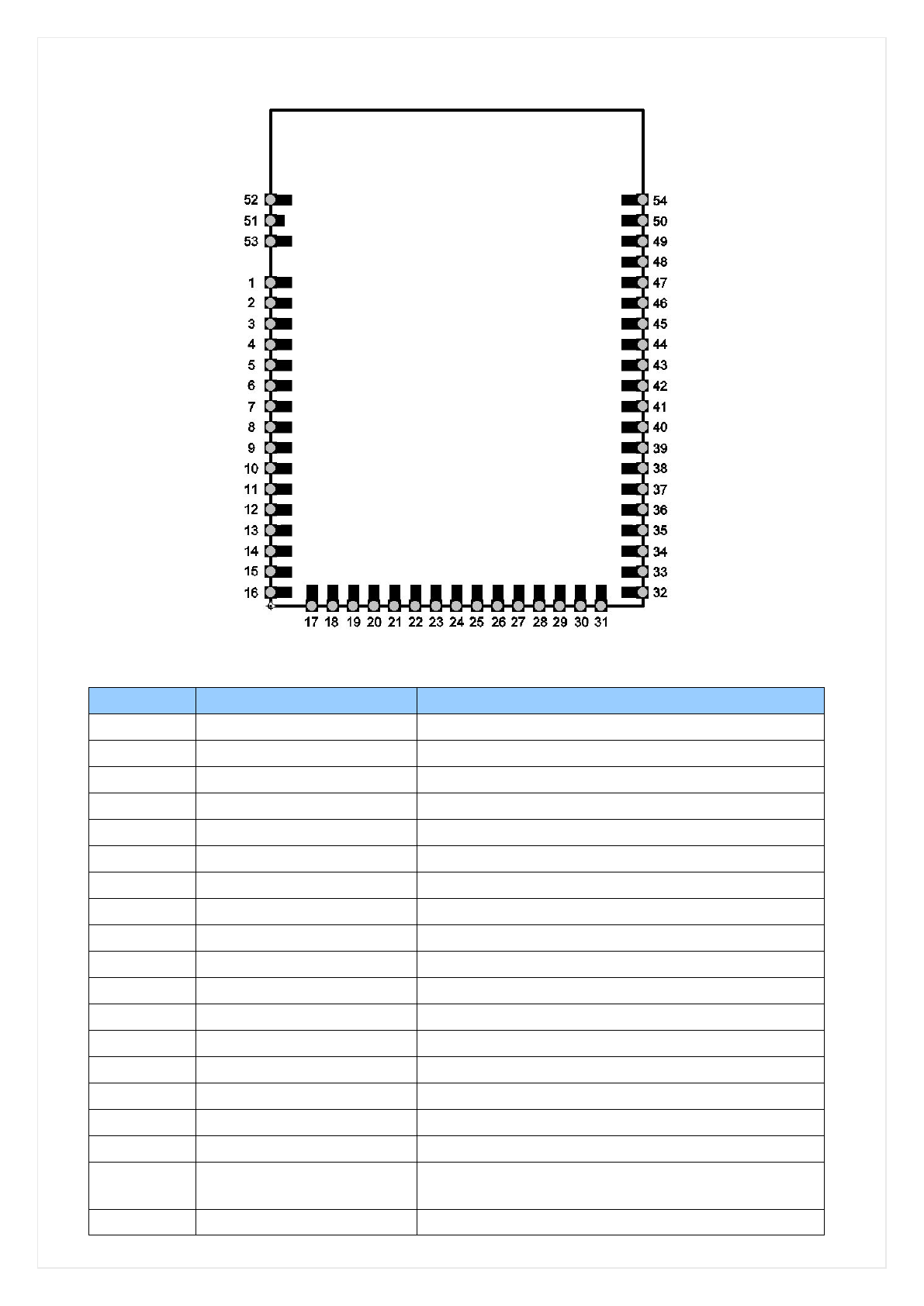
4.2 Pin Definition(Top View)
Pin Assignment
Pin# Name Description
1 GND Ground
2 GND Ground
3 NC Not Connected
4 NC Not Connected
5 NC Not Connected
6 NC Not Connected
7 VDDIO GPIOE and GPIOC group IO power
8 NC Not Connected
9 GPIO_4 GPIO Pin
10 GPIO_3 GPIO Pin
11 GPIOE_2/PWM2 GPIO Pin, PWM(multiplexing)
12 GPIOE_1/PWM1 GPIO Pin, PWM(multiplexing)
13 GPIOE_0 GPIO Pin
14 NC Not Connected
15 ADC_CH2 AD converter input
16 NC Not Connected
17 GND Ground
18 CHIP_EN 1: Enable Chip
0: Disable chip in shutdown mode
19 NC Not Connected

FN-LINK TECHNOLOGY LIMITED
Page10/12
20 NC Not Connected
21 NC Not Connected
22 GPIOA_3 GPIO Pin
23 NC Not Connected
24 GPIOA_5 GPIO Pin
25 GPIOA_6/UART0_RXD GPIO Pin, UART0_IN(multiplexing)
26 GPIOA_7/UART0_TXD GPIO Pin, UART0_OUT(multiplexing)
27 GND Ground
28 NC Not Connected
29 NC Not Connected
30 GND Ground
31 NC Not Connected
32 NC Not Connected
33 GND Ground
34 VD33 3.3V Power Supply
35 GND Ground
36 GPIOC_3/SPI0_MISO GPIO Pin, SPI0_MISO(multiplexing)
37 GPIOC_2/SPI0_MOSI GPIO Pin, SPI0_MOSI(multiplexing)
38 GPIOC_1/SPI0_CLK GPIO Pin, SPI0_CLK(multiplexing)
39 GPIOC_0/PWM0 GPIO Pin, PWM(multiplexing)
40 GPIOC_4/SPI0_CS1 GPIO Pin, SPI0_CS1(multiplexing)
41 GPIOC_5 GPIO Pin
42 GPIOB_3/I2C_SDA GPIO Pin
43 GPIOB_2/I2C_SCL GPIO Pin
44 GPIOB_1/UART1_RXD GPIO Pin, UART1_IN(multiplexing)
45 GPIOB_0/UART1_TXD GPIO Pin, UART1_OUT(multiplexing)
46 NC Not Connected
47 NC Not Connected
48 GND Ground
49 NFCIP_1 NFC input differential signal
50 NFCIN_1 NFC input differential signal
51 RF_1 WL RF signal
52 GND Ground
53 GND Ground
54 GND Ground
FN-LINK TECHNOLOGY LIMITED
Page12/12
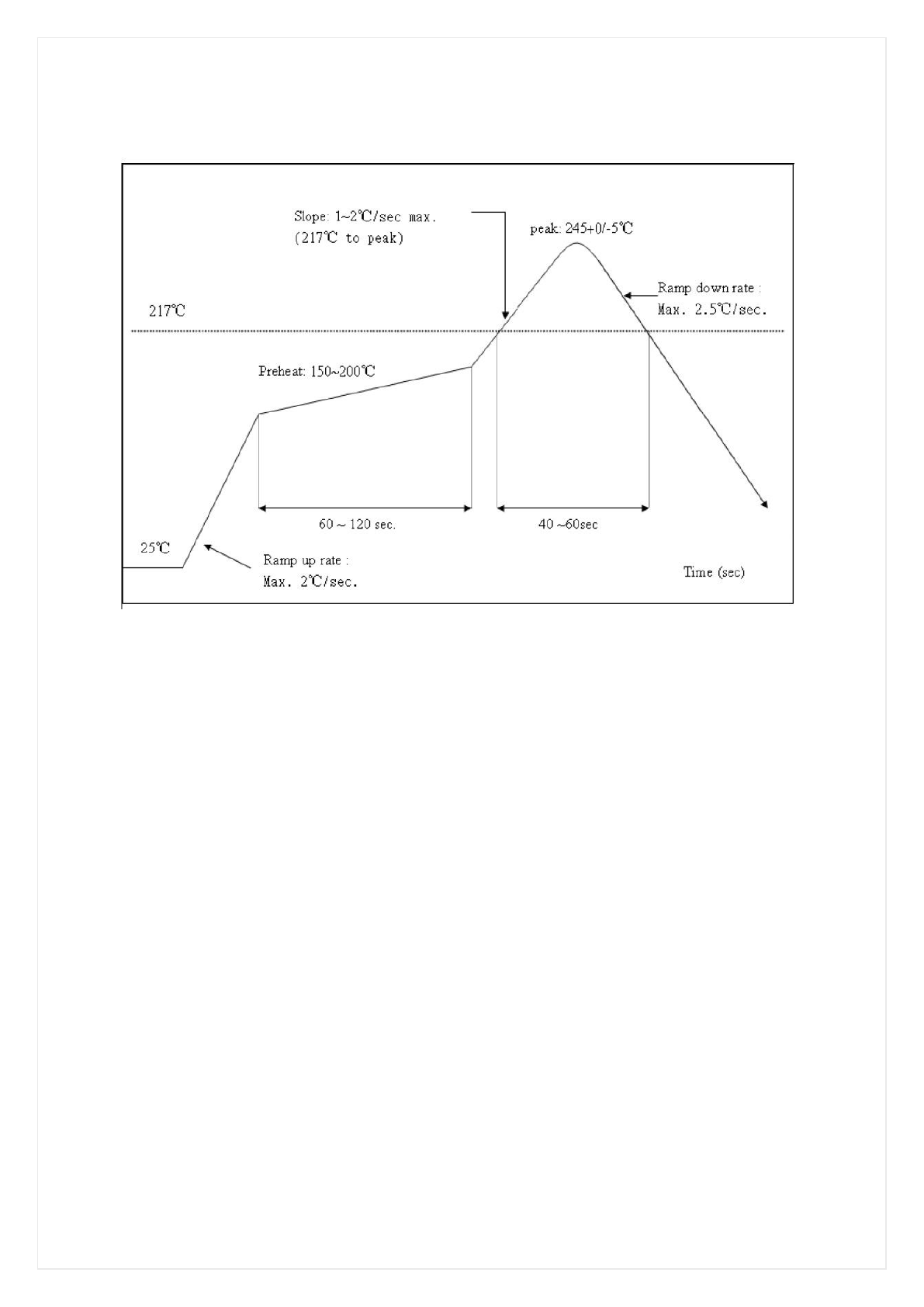
4.4 Recommended Reflow Profile
Referred to IPC/JEDEC standard.
Peak Temperature : <250°C
Number of Times : ≤2 times
4.5 Patch WIFI modules installed before the notice:
WIFI module installed note:
1. Please press 1 : 1 and then expand outward proportion to 0.7 mm, 0.12 mm thickness When open a
stencil
2. Take and use the WIFI module, please insure the electrostatic protective measures.
3. Reflow soldering temperature should be according to the customer the main size of the products,
such as the temperature set at 250 + 5 ℃for the MID motherboard.
About the module packaging, storage and use of matters needing attention are as follows:
1. The module of the reel and storage life of vacuum packing: 1). Shelf life: 8 months, storage
environment conditions: temperature in: < 40 ℃, relative humidity: < 90% r.h.
2. The module vacuum packing once opened, time limit of the assembly:
Card: 1) check the humidity display value should be less than 30% (in blue), such as: 30% ~ 40%
(pink), or greater than 40% (red) the module have been moisture absorption.
2.) factory environmental temperature humidity control: ≦30 ℃,≦60% r.h..
3). Once opened, the workshop the preservation of life for 168 hours.
3. Once opened, such as when not used up within 168 hours:
1). The module must be again to remove the module moisture absorption.
2). The baking temperature: 125 ℃, 8 hours.
3.) After baking, put the right amount of desiccant to seal packages.

WARING:
This device complies with Part 15 of the FCC Rules. Operation is subject to the following two conditions:
(1) T his devic e ma y n ot ca use h armful interference. ( 2) T his device must accept any interfer ence
received, including interference that may cause undesired operation.
NOTE: This equipment has been tested and found to comply with the limits for a Class B digital dev ice,
pursuant to Part 15 of the FCC Rules. These limits are designed to provide reasonable protection against
harmful interfe rence in a residential installation. This equipment generates uses and ca n radiate radio
frequency energy and, if not installed and used in accordance with the instructions, may cause harmful
interference to radio communications. However, there is no guarantee that interference will not occur in a
particular installation. If this equipment does cause ha rmful interference to radio or televi sion reception,
which can be determined by turning the equipment off and on, the user is encouraged to try to correct the
interference by one or more of the following measures:
---Reorient or relocate the receiving antenna.
---Increase the separation between the equipment and receiver.
---Connect the equipment into an outlet on a circuit different from that to which the receiver is connected.
---Consult the dealer or an experienced radio/TV technician for help.
WARNING: C hanges or modifications not expressly approved by the party responsible for comp liance
could void the user's authority to operate the equipment.
LABEL OF THE END PRODUCT:
The final end prod uct must be lab elled in a visible are a with the foll owing "Co ntains TX F CC ID:
2AATL-F11AMIM13-B1". If the size of the end product is smaller than 8x10cm, then additional FCC part
15.19 statement is required to be available in the users manual: This device complies with Part 15 of the
FCC Rules. Operati on is sub ject to the following two conditions: (1) this d evice may not cause harmfu l
interference, and (2) this device must accept any interference received, including interference that may
cause undesired operation.
RF Exposure
This device has been eval uated and sho wn compli ant with the F CC R F Exposur e limits under fix ed
exposure c onditions ( antennas are greater than 20cm from a p erson's body) when i nstalled in certa in
specific OEM configurations.
IMPORTANT NOTE:
This device is intended only for OEM integrators under the following conditions:
(1) According to F CC Part 15 Subpart C Se ction 15.212, the rad io elements of the mod ular transmitter
must have the ir o wn s hielding. Ho wever, d ue to t here is no shiel ding for this W IFI/BT module, this
module is granted as a Limited Modular Approval.
(2) This modul e has be en d esigned to op erate with E xternal anten na(I-PEX connector ) havi ng a
maximum gain of 0dBi. The module is only certif ied with the installed antenna. An y change of the
antenna will void the certification.
(3) Integration is typically strictly restricted to Grantee himself or dedicated OEM integrators under control
of the Grantee . The modul e will be res ponsible to satisfy SAR/RF Exp osure req uirements, when the
module int egrated into any (portable, mob ile, fix ed) h ost device. T his modu le is int ended for OEM
integrator on ly and the OEM integr ators an d instructe d to ensure th at the e nd us er h as no ma nual
instructions to remove or install the device. T he OEM i ntegrator is still res ponsible for the FC C
compliance requirement of the end product, which integrates this module.
The module has no sh ielding an d tested s tand alone. This modu le is te sted an d approved as Limited
modular ap proval with stand alon e configuration, an y OE M incorpor ated this radio m odule into a ny
system are require additional testing and evaluation.
EU Regulatory Conformance
Hereby, we (F N-Link T echnology Limited) declared that this device is in compliance with the essenti al
requirements and other relevant provisions of Directive 1999/5/EC.