Hanatech MULTISCAN Automotive Handheld Scantool User Manual User s Manual H
Hanatech Co.,Ltd Automotive Handheld Scantool User s Manual H
UserManual.wiki
>
Hanatech
>
MULTISCAN User Manual
users manual
Navigation menu
Upload a User Manual
Namespaces
Wiki Guide
HTML
PDF
Info
Views
User Manual
Discussion / Help
Navigation
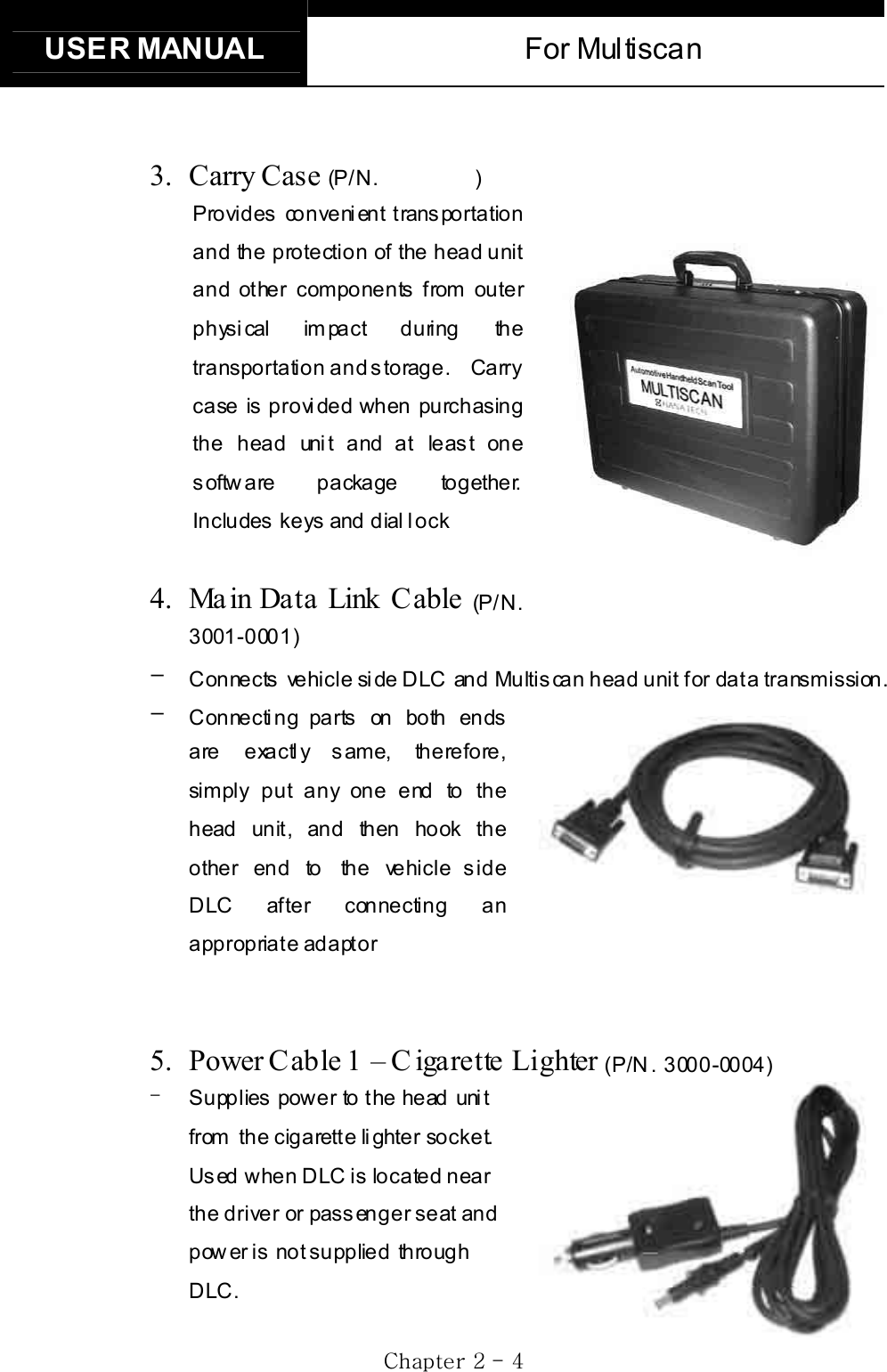
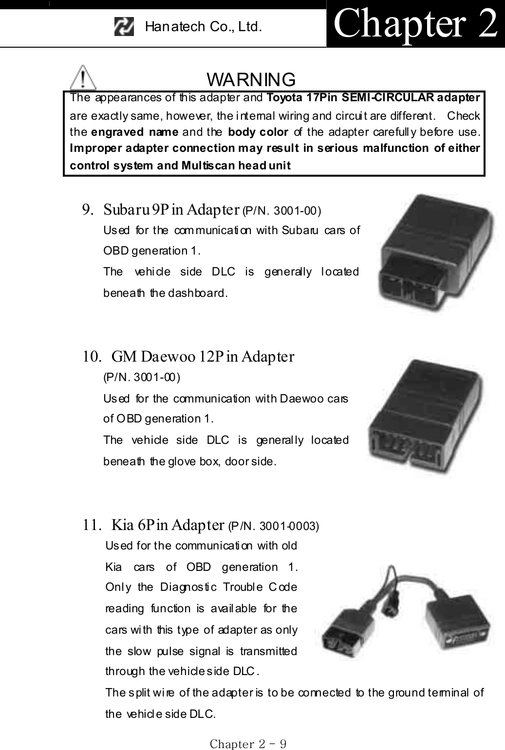
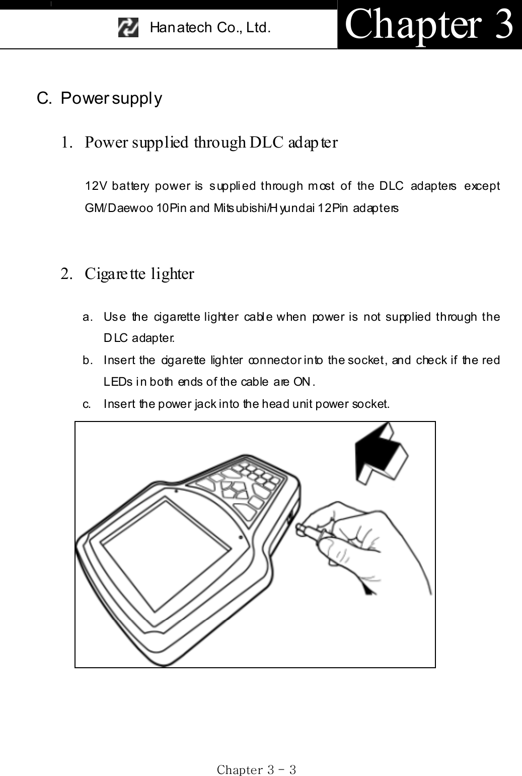
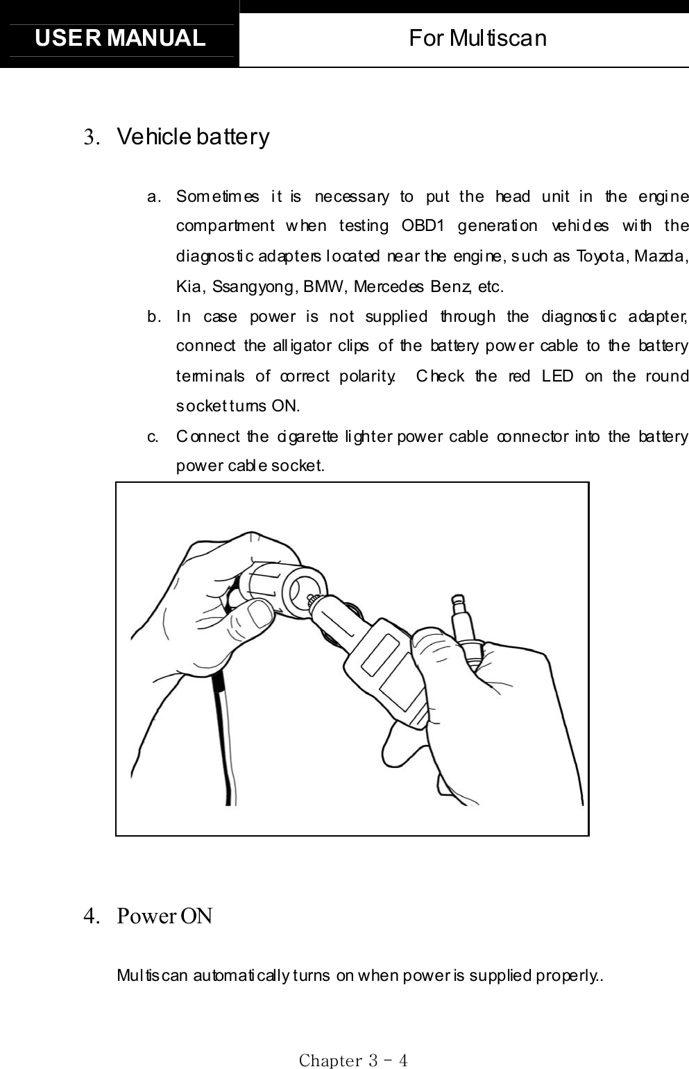
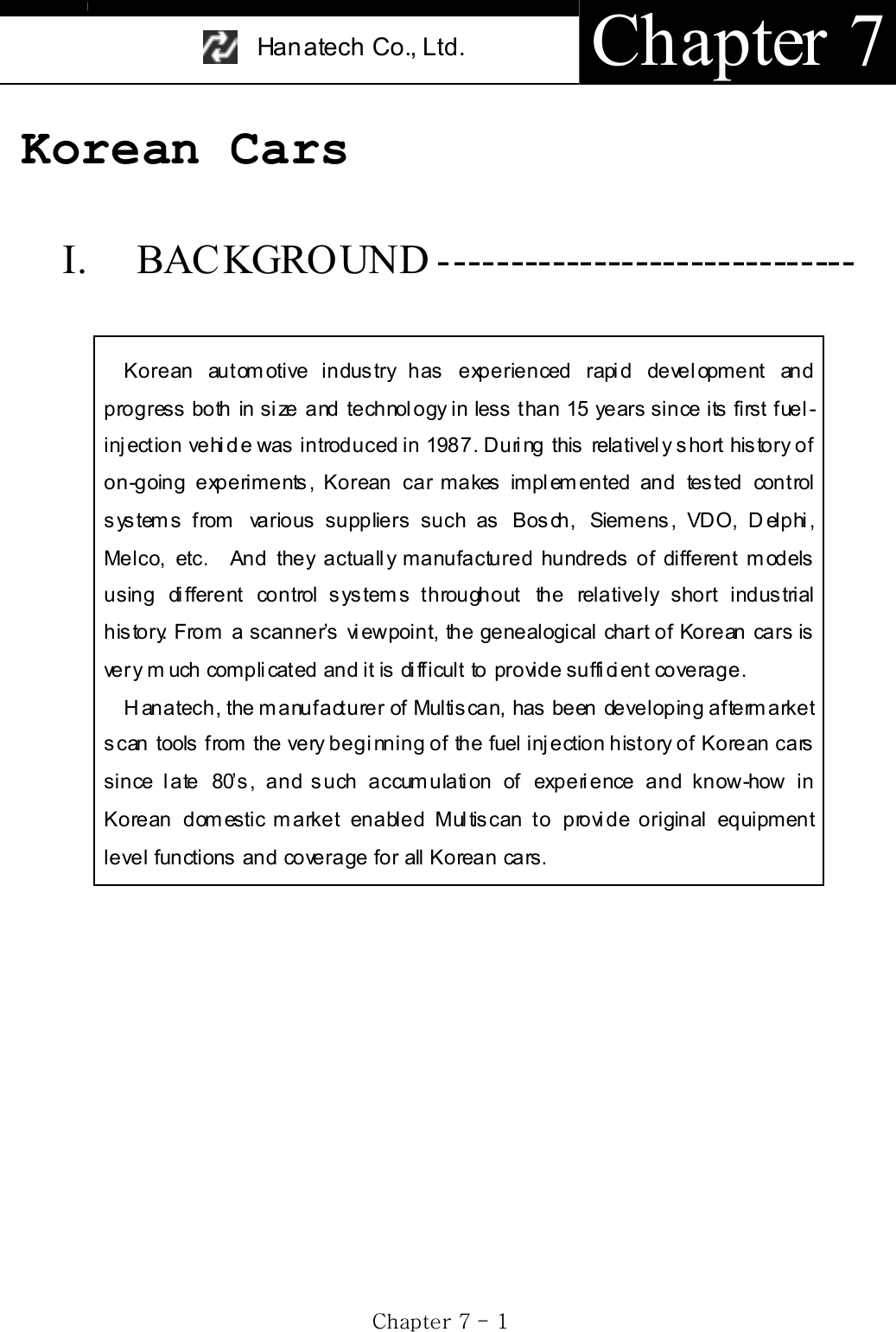
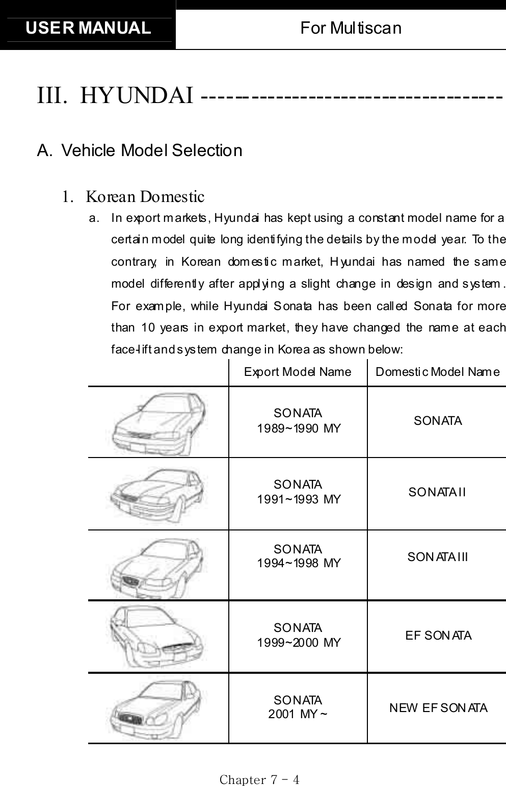
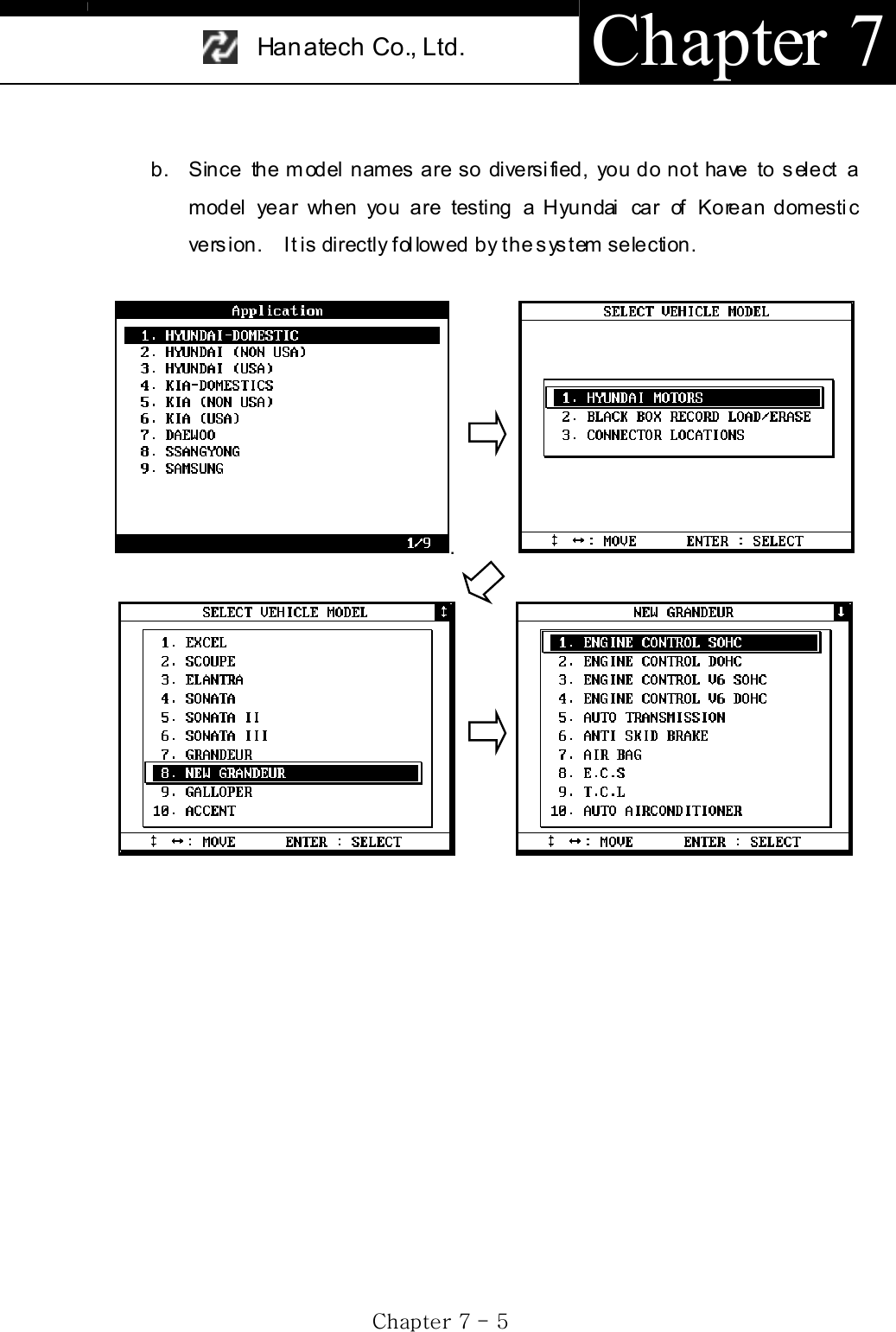
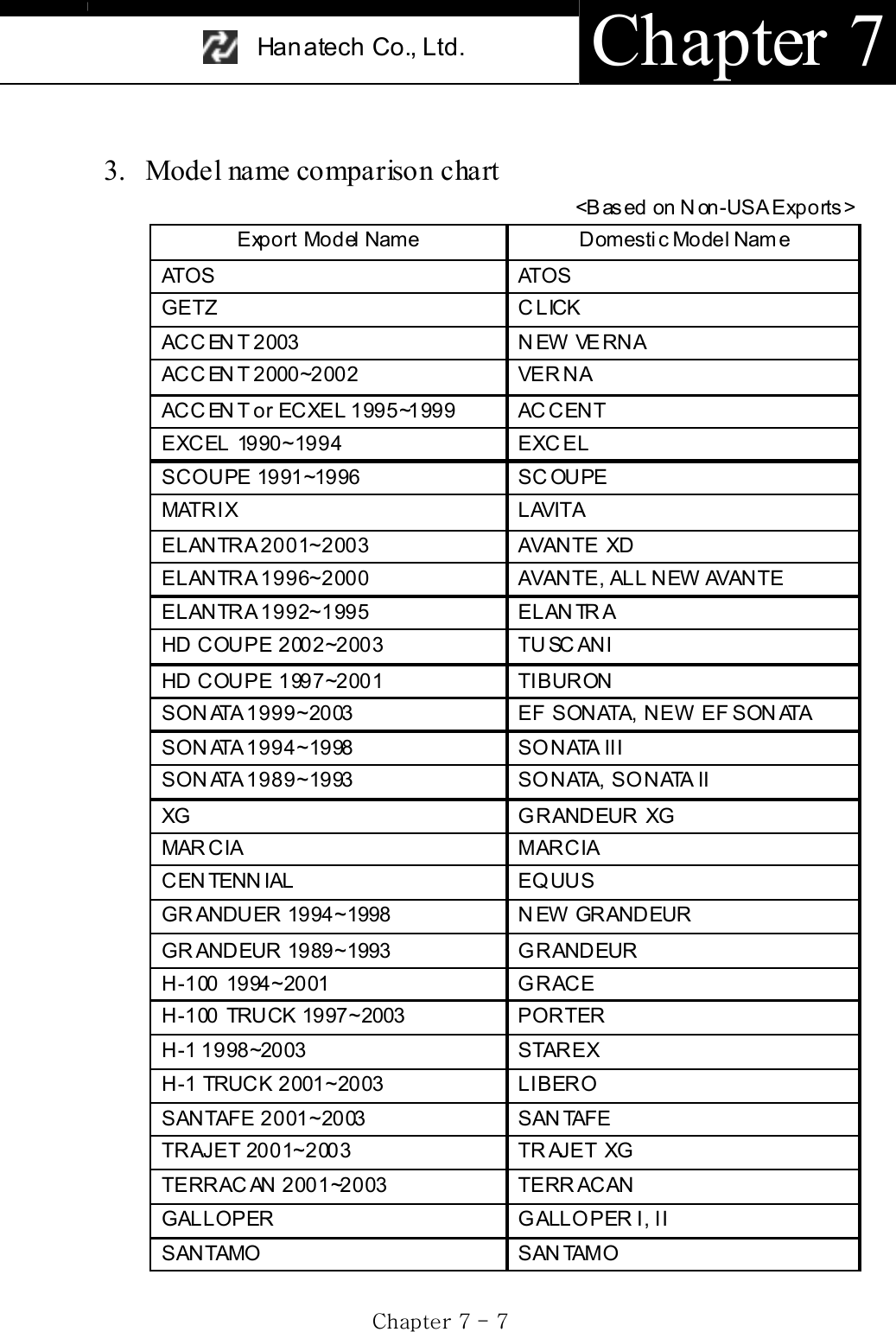
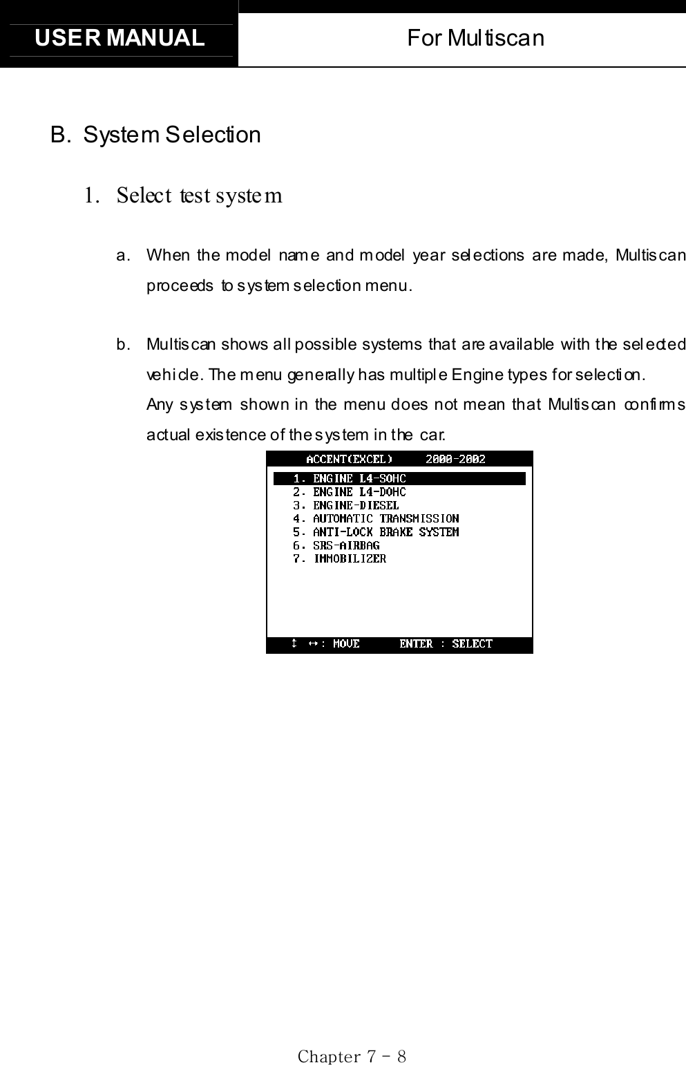
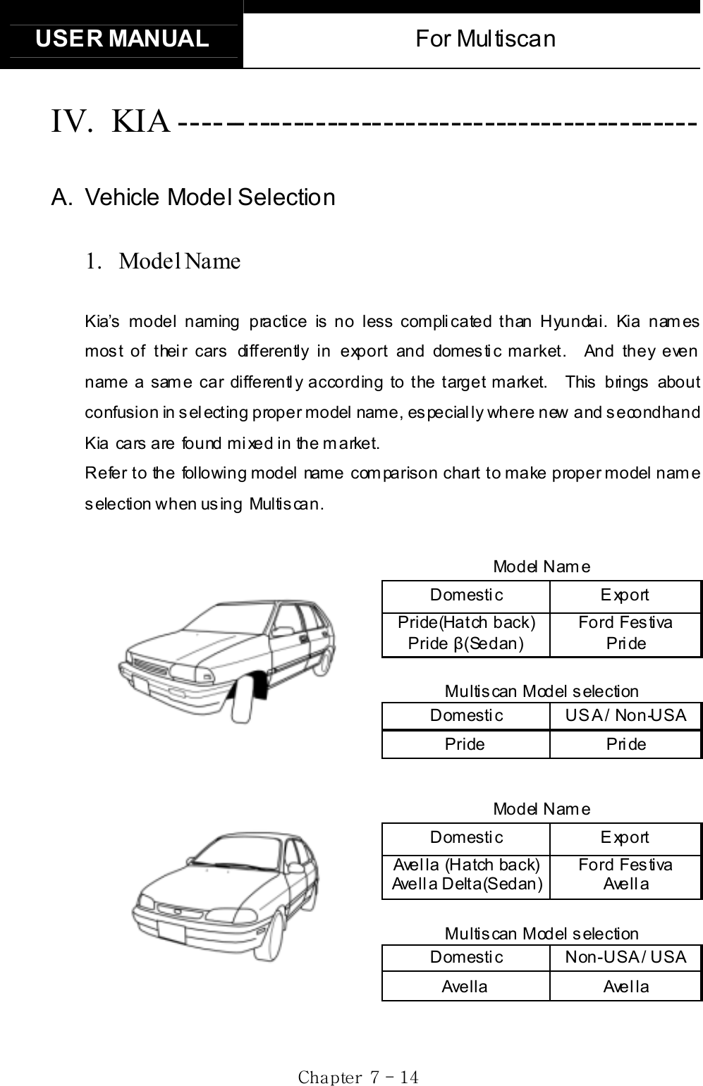
![USER MANUAL For Multiscan GjGXGTG ]GGIII. WARRANTY SERVICE ------------------------- Warranty PeriodIn principle, Multiscan is warranted to the consumer to be free of defects in material and workmanship for the period of 3 years after the date of purchase. If the product is found defective during this period, the product can be returned to Hanatech and will be repaired or replaced free of charge. Freight and repair Cost For the repair of head unit, Hanatech covers the freight cost for the service during one year from the date of purchase, and you can send the troubled unit to your local distributor without having to pay the freight cost. You should consult with your local distributor about the validity of remaining warranty period before sending the unit. For the remaining two years, you are liable for any international cost incurred. Repair or replacement will be provided free of charge. When the warranty period is expired after three years, the customer must pay the round trip freight and the repair or replacement cost. Upon delivery Hanatech inspects all the ordered product parts and components are included in the package before shipment, and includes the original copy of pre-shipment inspection report in the box. As soon as the product is delivered to you, please ensure everything you ordered is properly checked and included referring to the pre-shipment inspection report. If there is anything missing or damaged, you must notify the local distributor immediately within 3 working days from the delivery date for free of charge replacement of the parts. In case of trouble If you encounter any malfunction or trouble with the equipment, please refer to the Trouble Shooting chapter in this manual. If the problem cannot be solved, please contact your local distributor for assistance. For early identification of a fault or error,](https://usermanual.wiki/Hanatech/MULTISCAN/User-Guide-415188-Page-9.png)


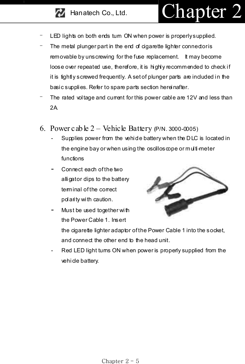
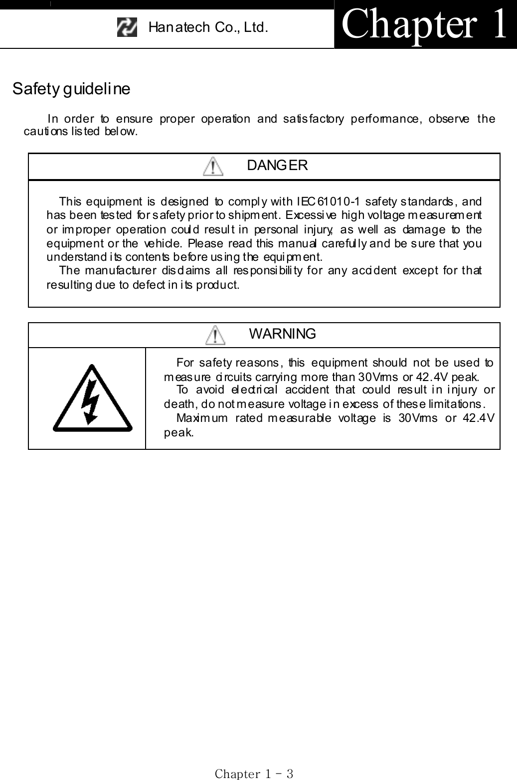
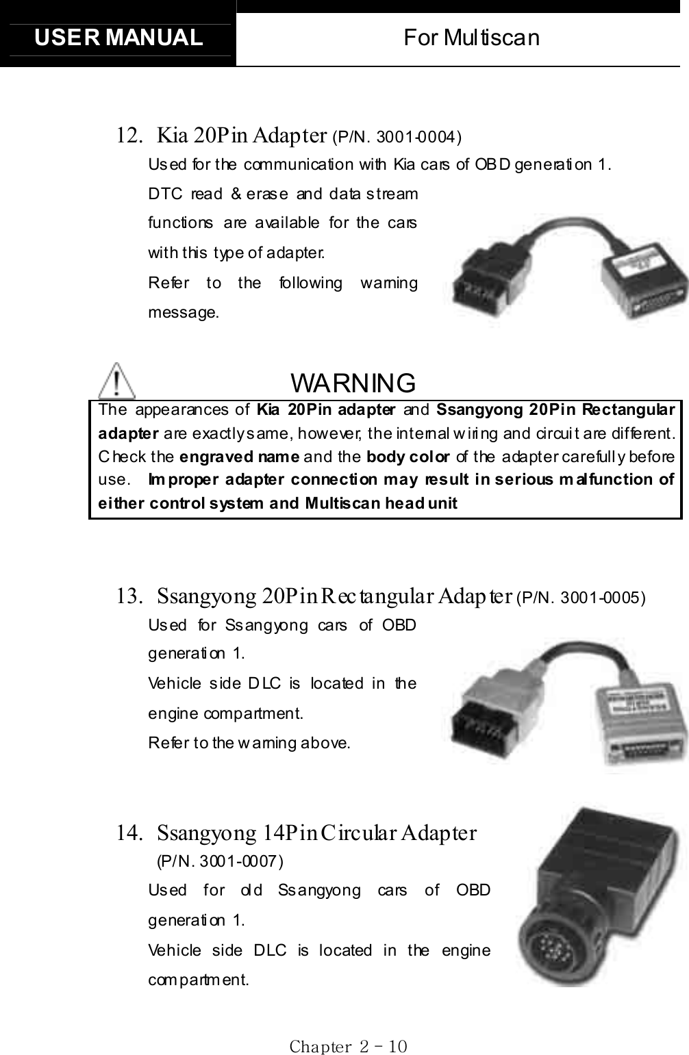
![USER MANUAL For Multiscan GjGYGTG ]GB. Diagnostic Adapters Diagnostic adapters are sold separately, therefore check if all the adapters you ordered are included in the package upon delivery. There are two types of adapters: capsulated and wired types. Mos t of Mul tis can DLC adapters are capsul ated for bett er durability and s torage, however, s om etimes i t is diffi cult or alm ost im possible to connect t he capsulated adapter to vehicle side DLC when it is located deep inside beneath t he das hboard. W e use wi re type adapters for t he cars s uch as Hyundai and Kia that we were reported to have such connecting difficulties. Capsule type Wire type 1. OBD2 Sta ndard Adapter (P/N. 3001-0010)Used for all OBD generation 2 and EOBD com pa tible ve hicl es . Vehi cle side D LC is generally located near the driver’s seat and most frequently found beneath the dash panel. 2. Toyota / Lexus 17Pin Rectangular Adapter (P/ N. 3001-0011)Us ed for t he diagnosis of Toyota and Lexus of OBD generation 1. Vehicle s ide D LC of this type is generally located in the engine com pa rtm en t .](https://usermanual.wiki/Hanatech/MULTISCAN/User-Guide-415188-Page-18.png)
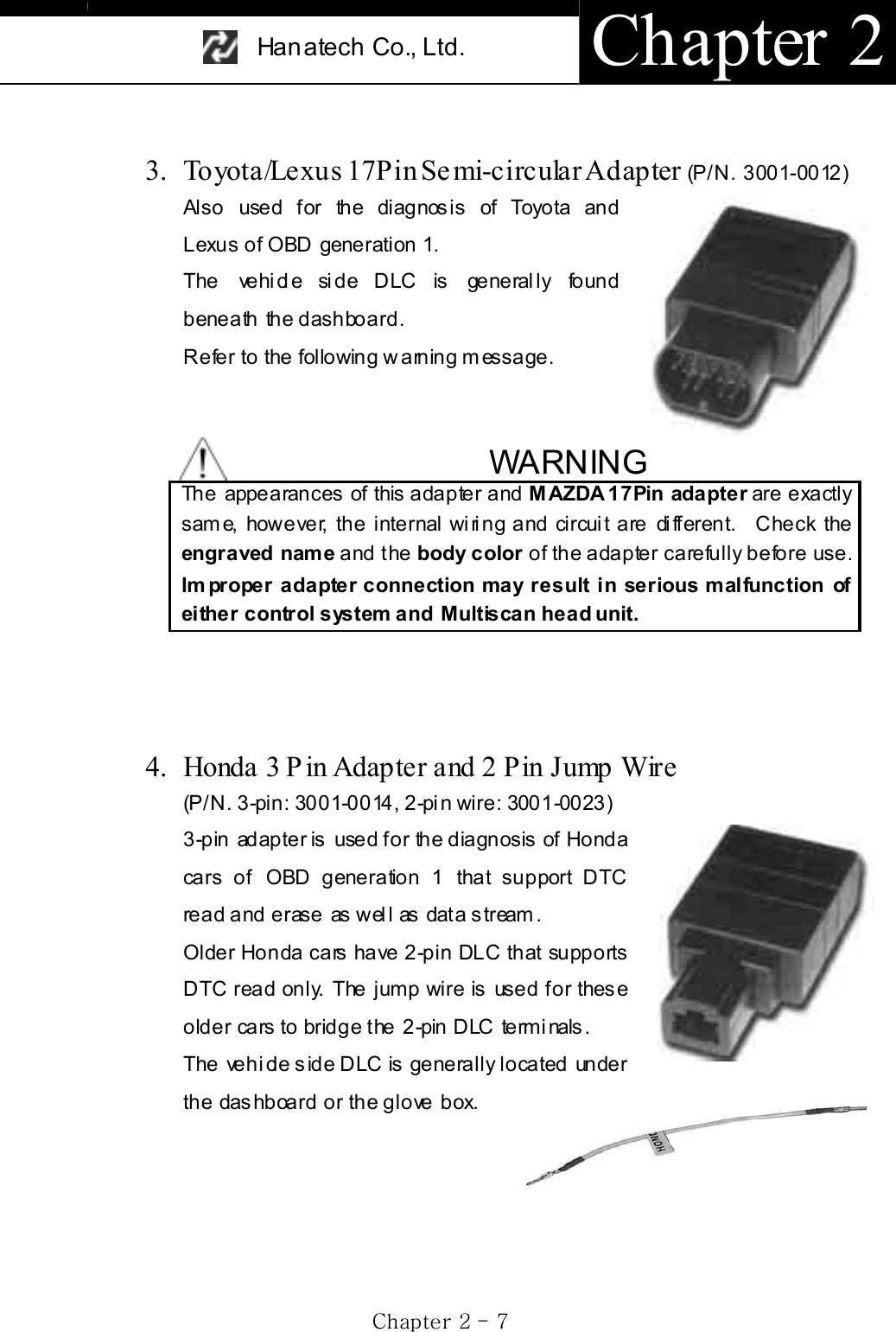
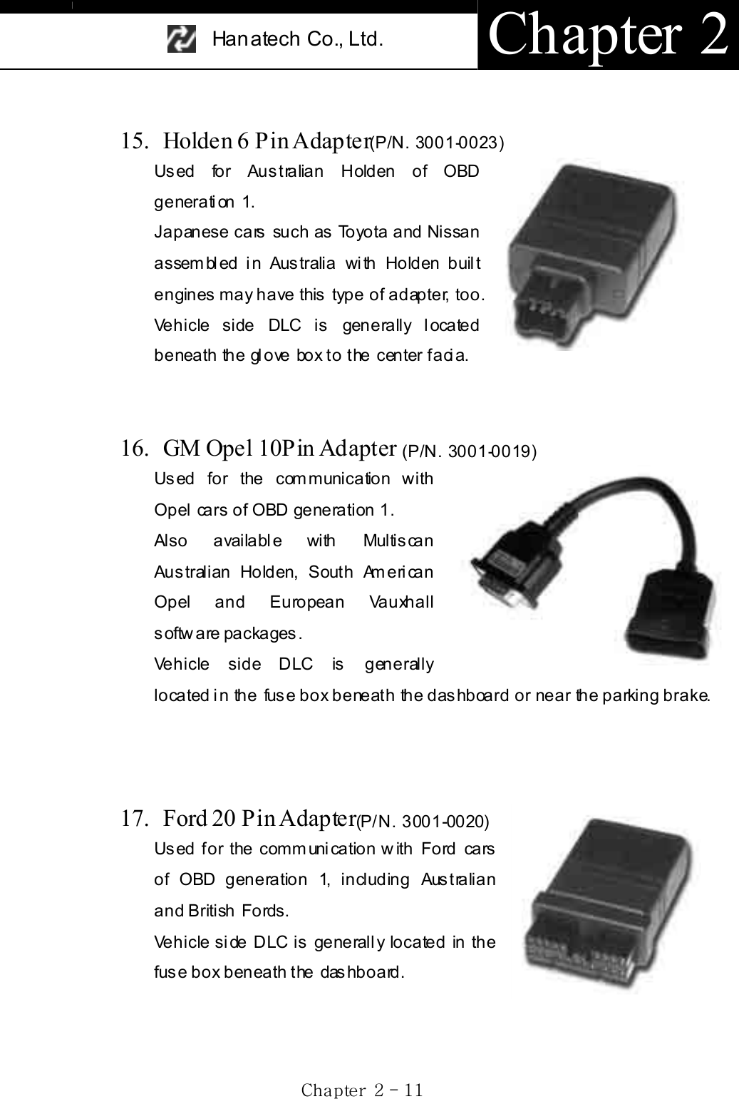
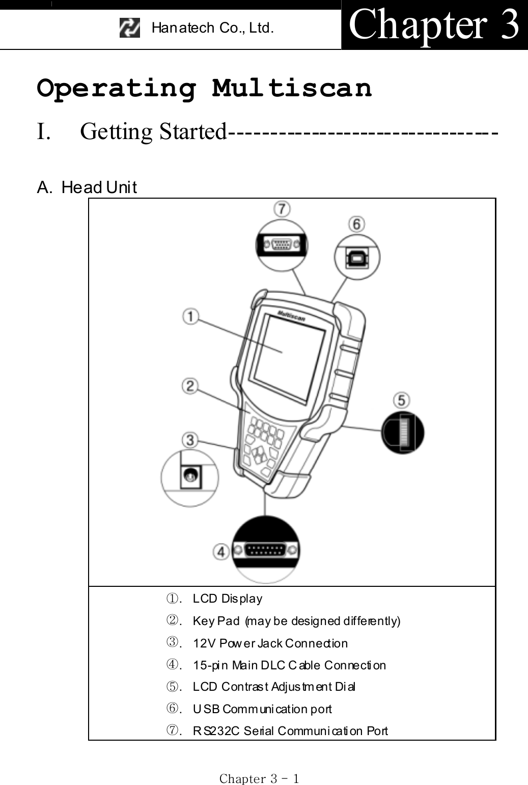
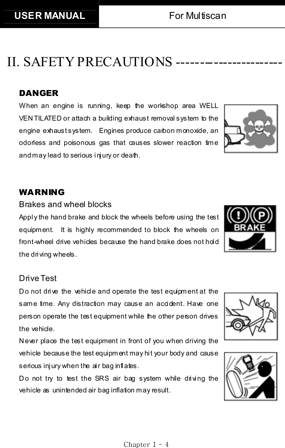
![USER MANUAL For Multiscan GjGZGTG ]GII. Control Keys ----------------------------------- A. Keypad The keypad is made of chemistry proofing PVC material that prevents contamination and damage from hazardous oily workshop environment. The membrane keypad is designed and tested to maintain its normal operation over a million keystroke for each. Each key is rais ed for better tactile feel. The keypad has total of 20 keys . B. Making selec tio n i n the me nu 1. Numeric Keypad in the bottom Sim pl y press the corres pondi ng num ber when m aki ng s el ection from a menu. This is available only when you are selecting an item of which number is 9 or less. For more than 10, you should locate the highlighted bar on the desired item and press the [ENTER] key. 2. Arrow keys in the middle](https://usermanual.wiki/Hanatech/MULTISCAN/User-Guide-415188-Page-32.png)
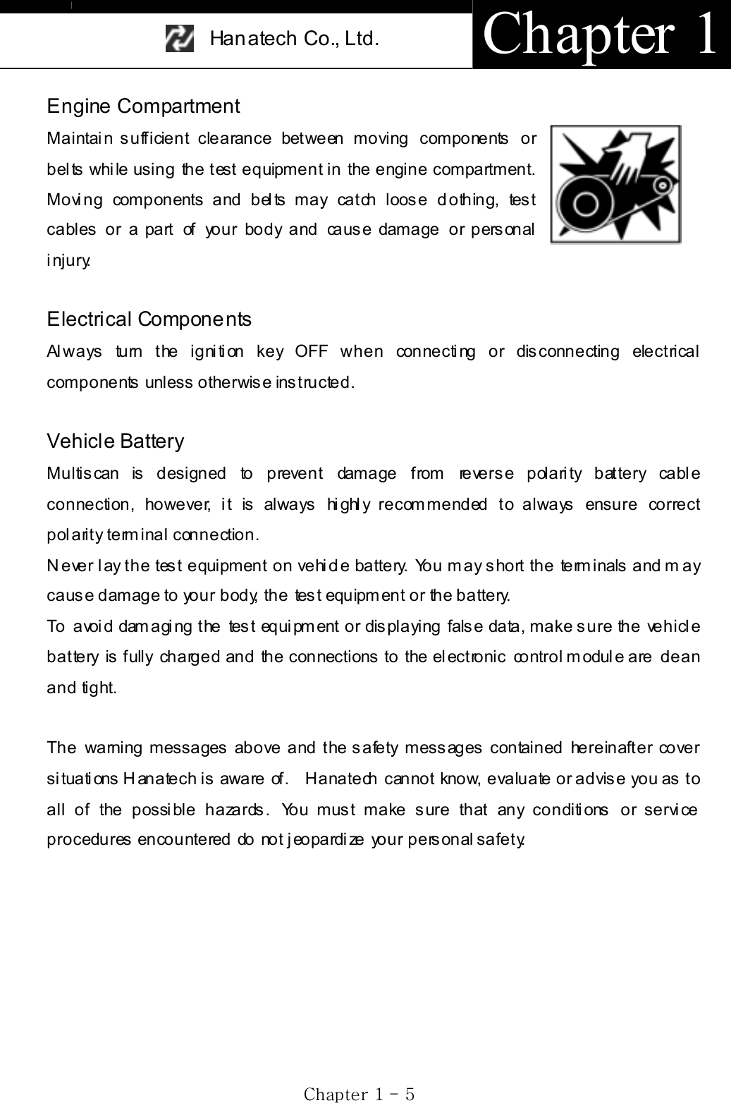
![Han atech Co., Ltd. Chapter 3 GjGZGTG ^Gൖ ൘ Page Up/Down Scroll Up/ Down a. Scroll up and down the highlighted bar in the menu by pressing Up/Down arrow keys and press the [ENTER] key to confirm the selection. b. If the menu has more than 12 items, you may have to move between the pages t o make selection. You do not have to pound on Up/Down arrow keys to s croll the whole page. Sim pl y press ing the Left or Right arrow key will shift page to page. Move the highlighted bar by pressing the up/down keys when the desired item appears on the screen, and press t h e [ EN T ER ] ke y.c. If differently defined, key instructions will be given in the bottom of the s creen. C. Func tio n keys 1. ESC Used to abort an operation of Multiscan or to return to the upper level menu. If differently defined, key instructions will be given in the bottom of the screen.2. HELP a. DTC Read -When a trouble code is detected, you can press this key to view the detailed information of the DTC. -DTC definition, DTC registration conditions and check points are provided (For Korean and Malaysian cars only as of May, 2003)](https://usermanual.wiki/Hanatech/MULTISCAN/User-Guide-415188-Page-33.png)
![Han atech Co., Ltd. Chapter 3 GjGZGTG `GIII. Configuration ---------------------------------- Press the [3] key from the initial function menu to proceed to the configuration menu. You can check the version numbers of the software packages contained in the built-in 128MB memory, test the keypad and LCD, set up sound and language options and download software updates in the configuration menu. A. Software Information When you select [1. SOFTWARE INFORMATION] in the configuration menu, a list of software packages contained in the built-in memory will appear as below: Should you get any update files from your local distributor or from Hanatech website, please compare the version number and last update date to check if the update is necessary.](https://usermanual.wiki/Hanatech/MULTISCAN/User-Guide-415188-Page-35.png)
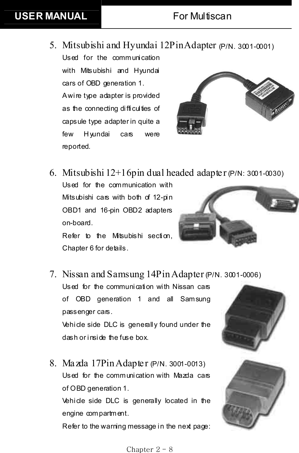
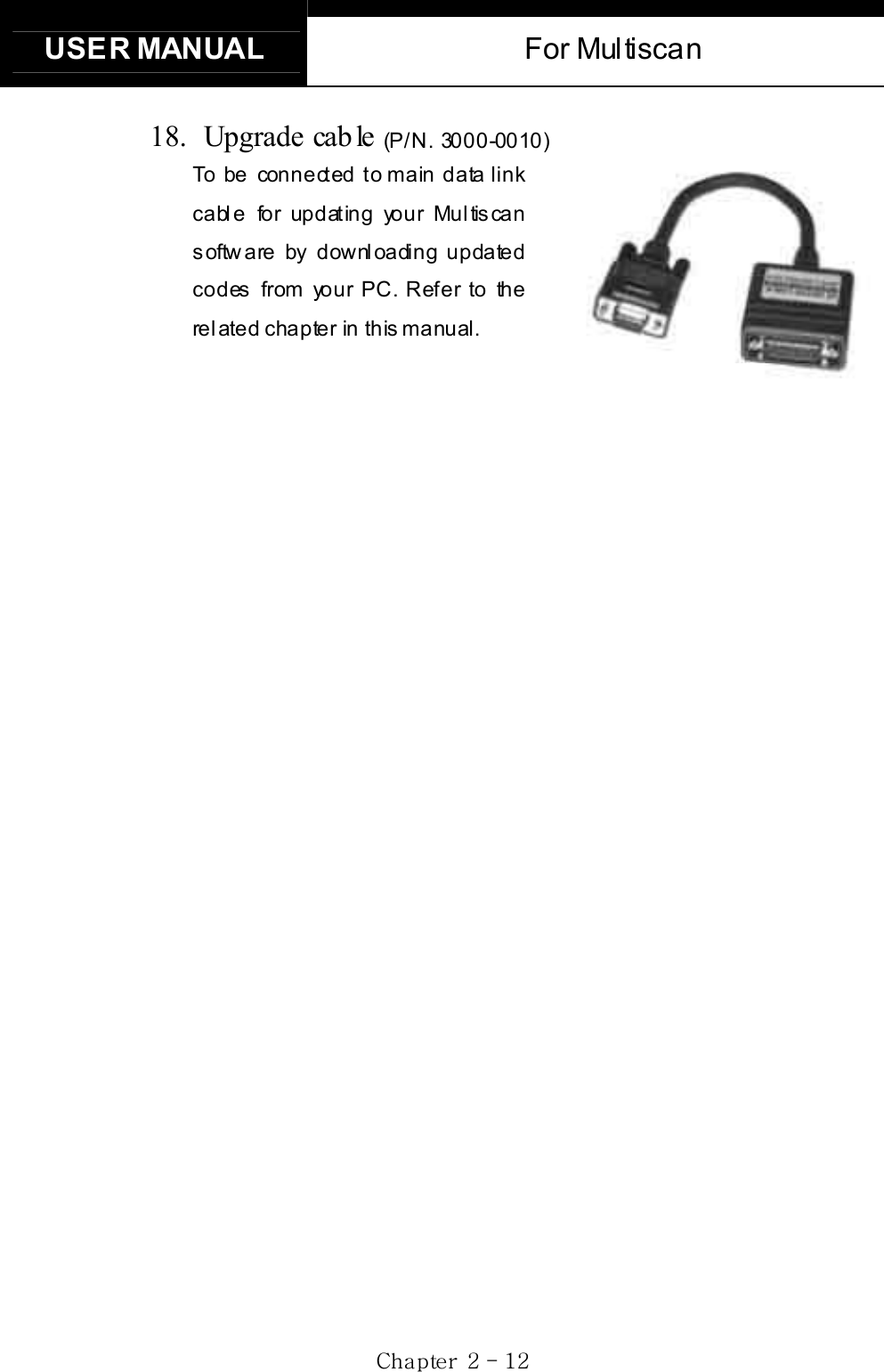
![USER MANUAL For Multiscan GjGZGTGXWGB. Special functions G1. Download software -You can download the software updates from your PC when you s elect [1. D OWNLOAD SOFTWARE]. -Instructions will be given separately whenever an update is available. Contact your local distributor for the availability of update frequently and keep posted of such events. 2. Language-You can select provided language. English and Spanish languages are available for selection as of March 2004. 3. Sound -You can toggle ON and OFF the key sound. 4. Save Configuration -If you have made any change in this [Special Function] menu, you have to save the confi gurati on to m ake such changes ef fective. -Press the [4] key to save the changes in configuration](https://usermanual.wiki/Hanatech/MULTISCAN/User-Guide-415188-Page-36.png)

![Han atech Co., Ltd. Chapter 4 GjG[GTG \GC. DTC Help tips a. Help tips are provided when you press the [HELP] key after locating the highlighted bar on one of the detected trouble code(s). This function is available when Multiscan detects one or more trouble code(s) b. Help tips including trouble code definition, conditions and check points are provided for all Korean cars and Malaysian cars as of May 2003. Wiring diagrams are also provided for Korean cars of 2000 model-year or older. c. Press the [ESC] key to return to DTC list.](https://usermanual.wiki/Hanatech/MULTISCAN/User-Guide-415188-Page-42.png)
![USER MANUAL For Multiscan GjG[GTG ]GII. Current Data ----------------------------------- (= Da ta S tream, Live Da ta, Service Da ta ) A. Pulse Signal Type a. Data stream is not generally supported for this type of old cars because the s peed of puls e signal com munication is too sl ow to read the data st ream variables . b. Some of old Toyota cars using 17-pin rectangular adapter exceptionally support data readings as the system supports relatively high speed pulse signal comm uni cation. B. Serial Communicatio n Type a. Most of control systems with serial communication support data stream function. Sel ect [C urrent data] from the menu, then the data readings follow. b. Some systems like SRS or ABS may be designed not to support data stream on purpose by the car manufacturer while the other systems are supported. A scanner is a passive tool that reads inform ation from the control system, and it is unable to actively generate information that the system does not provide. c. Some old OBD1 generation Korean and European cars equipped with Bosch control system that communicates in ISO9141 protocol provide relatively slower communicati on s peed. Data s ampling may seem slow with these cars](https://usermanual.wiki/Hanatech/MULTISCAN/User-Guide-415188-Page-43.png)
![Han atech Co., Ltd. Chapter 4 GjG[GTG ^GC. Data Freeze The [Data Freeze] function places the selected data stream variable on top of the LCD screen so that the user can check and compare desired sensor values continually without having to scroll up and down. This i s different from ‘Freeze Fram e Data’ function of Generic OBD2. 1) Step One Select a desired sensor using the [ൖ][൘] and the [][] keys. 2) Step Two Press the [ENTER] key to freeze the selected sensor. i.e., when O2 sensor and MAP sensor are selected and frozen, these sensor values will be placed at the top of the display as below : 3) Step ThreeUp to five sensors may be frozen at a time. For example, if the Injection Time, which can be shown when scrolled down, is selected and frozen, Injection Time value will be placed below the previously frozen O2 and MAP sensor.](https://usermanual.wiki/Hanatech/MULTISCAN/User-Guide-415188-Page-44.png)
![USER MANUAL For Multiscan GjG[GTG _GD. Data Graph Multiscan provides the [Data Graph] function for more efficient data an alysis . a When you press the [1] key after locating the highlight bar on the desired sensor, the sensor data graph will be displayed as shown below. b You can display up to 3 graphs in a screen by choosing the sensors as previously explained [Data Freeze] procedure - Press the [Enter] key after locating the highlight bar on the desired sensor, and then press the [1] key. When more than 4 sensors are selected, the graphs of upper three sensors will be displayed.](https://usermanual.wiki/Hanatech/MULTISCAN/User-Guide-415188-Page-45.png)
![Han atech Co., Ltd. Chapter 4 GjG[GTG `Gc For each sensor data graph, the name of the sensor and its current value will be simultaneously displayed together. d To change the sensor, go back to the previous Service Data display by pressing the [Esc] key, and then choose other sensors. e To halt the graph output, press the [ENTER] key. It will resume when you press the [ENTER] key again.](https://usermanual.wiki/Hanatech/MULTISCAN/User-Guide-415188-Page-46.png)
![USER MANUAL For Multiscan Gj G[G TGXWGE. Help tips a When you press the [HELP] key after locating the highlight bar on a certain data stream variable, the help message will be displayed. This works the same for detected Trouble Codes in [Self Diagnosis] function. b Detailed information including conditional standard range on the selected sensor will be displayed as shown below. c Press t he [ESC ] key to go back to the data s tream dis pl ay.](https://usermanual.wiki/Hanatech/MULTISCAN/User-Guide-415188-Page-47.png)
![USER MANUAL For Multiscan Gj G[G TGXYGA. Menu Selectiona Choose [ACTUATION TEST] from the function Selection Menu b The name of the actuator to be tested, test method and the test condition are shown in the display. Available actuators, test methods and condi tions m ay di ffer in each vehi cl e. B. Test S ta r t 1. Selecting Test Item a Choose an actuator to test from the menu by using the [] and [] keys. b Check the test conditions and press the [ENTER] key when all the conditions are met. 2. Testing a [TESTING...] message will be displayed during the actuation test Test method means how the actuation test will be performed. Check the actual reaction of the actuator b In the example below, the injector will stop injecting fuel for 6 seconds](https://usermanual.wiki/Hanatech/MULTISCAN/User-Guide-415188-Page-49.png)
![Han atech Co., Ltd. Chapter 4 Gj G[G TGXZGwhile engine is idling, and it will make engine stall or unstable. c Testing a fan or an injector is easy to check the proper reaction as it generates distinctive changes in vehicle condition such as fan whining or unstable idling. However, valves or motors are generally tested while engine is stopped and all you can hear may be a small and unclear electric buzzing sound. Test in a quite place and observe the test results carefull y. d When the test is completed, the [TEST COMPLETE] message will be displayed. You can choose other actuators by using the [] and []keys. Press the [ESC] key to quit test mode.](https://usermanual.wiki/Hanatech/MULTISCAN/User-Guide-415188-Page-50.png)
![USER MANUAL For Multiscan Gj G[G TGX[GٻIV. Black Box -------------------------------------- Just like the 'Black Box' or a ‘flight recorder’ of an aircraft, Multiscan can 'record' data stream during the vehicle drive test and the recorded data can be 'retrieved' later for intensive analysis of vehicle's condition. A. Func tio n sele ctio n Choose [#. Black Box D ata] from the [Function Selection Menu] after selecting Origin, Car Manufacturer, Model name and system to test.](https://usermanual.wiki/Hanatech/MULTISCAN/User-Guide-415188-Page-51.png)
![Han atech Co., Ltd. Chapter 4 Gj G[G TGX\GB. Capacitya Duri ng a norm al tes t, the [Data Stream ] frames pass by in rapi d s uccessi on, and cannot be recalled unl ess the data has been s aved. Thanks to its extensive internal memory, Multiscan can record up to 2040 frames of Data Stream for multiple cars. b By loading the recorded data, you can diagnose sensor data frame to frame without missing a single cri tical moment. B. Memo ry Check a. Multiscan checks its internal memory before it starts recording Black Box data. If there is no sufficient free memory space available, Multiscan will suggest deleting one or more of previous record(s). b. Press the [ERASE] key to proceed, then a list of saved data will follow. Locate the highlight bar on data to delete, and press t he [EN TER ] key. A query for your confirmation will follow. Press the [YES] key to erase otherwise press the [NO] key.](https://usermanual.wiki/Hanatech/MULTISCAN/User-Guide-415188-Page-52.png)
![USER MANUAL For Multiscan Gj G[G TGX]GC. PID(Live data parame ter) selection a You are required to s el ect the param eters to record. b Multiscan will show you the whole live data parameters available in the control system you selected. Locate the highlight bar on the desired parameter and press the [ENTER] key. Selected parameter will be marked star(*). You can also deselect the parameter by repeating the procedure. c You can select up to 40 PIDs to record. Press the [ESC] key when the selection is completed, then Multiscan will start recording data.](https://usermanual.wiki/Hanatech/MULTISCAN/User-Guide-415188-Page-53.png)
![Han atech Co., Ltd. Chapter 4 Gj G[G TGX^GD. Trigger Modes There are three trigger modes in the black box function. a Continuous Record Mode (No trigger m ode) -Multis can will record li ve dat a of s elect ed parameters up to 2040 fram es or until you press the [ESC] key. -Percentile memory usage and sampling time(frequency) will appear in the center of the screen while recording data, and the actual live data values will remain unchanged. -Since no DTC trigger is applied in this mode, number of “Before DTC” frames will remain 0, and the “After DTC” will keep increasing as the more frames are recorded.](https://usermanual.wiki/Hanatech/MULTISCAN/User-Guide-415188-Page-54.png)
![USER MANUAL For Multiscan Gj G[G TGX_Gb Autom atic Trigger Mode (Triggered by DTC) -Multiscan will keep recording live data of selected parameters up to 128 fram es . -Once a DTC is detected or the [ESC] key is pressed by the user, it will proceed with recording remaining frames up to 2,040 or until you abort. -This function will let you have a set of data stream before and after the ECM’s DTC recognition when you perform the test drive. -Before DTC, you will see the Live Data of the selected parameters keep refreshing, however, once triggered by DTC or [ESC] key stroke, only the percentile process information and sampling frequency will be displayed.](https://usermanual.wiki/Hanatech/MULTISCAN/User-Guide-415188-Page-55.png)
![Han atech Co., Ltd. Chapter 4 Gj G[G TGX`Gc Manual Trigger M ode -Multiscan will keep recording live data of selected parameters up to 128 frames, and once the [ESC] key is pressed by the user, it will proceed with recording remaining frames up to 2040. -The s creen dis play is t he sam e as when selecti ng the Auto Trigger Mode.](https://usermanual.wiki/Hanatech/MULTISCAN/User-Guide-415188-Page-56.png)
![USER MANUAL For Multiscan Gj G[G TGYWGE. Saving the recorded data a When the total frame number reaches 2040 or when you press the [ESC] key to abort, a query asking you if you would like to save recorded data or to discard it. Press [YES] to save or [NO] to cancel. b When pressed [YES], a dialog box follows and asks you to input the test date. Enter the date and press the [ENTER] key to save the recorded data to Multiscan memory. Pressing the [ESC] key cancels saving data. Date form at is DD-MM-YYYY(D-day, M-month, Y-year), and only numeric values are available. c Tested Vehicle model name and control system will be saved as well as the date s tamp for future retri eval .](https://usermanual.wiki/Hanatech/MULTISCAN/User-Guide-415188-Page-57.png)
![Han atech Co., Ltd. Chapter 4 Gj G[G TGYXGF. Black Box Da ta Load a You can load saved data by choosing [BLACKBOX RECORD LOAD / ERASE] from the [Car Manufacturer Selection] menu as shown below: b A list of recorded Black Box Data will follow for your selection Up to 4 back box data can be stored in the memory per car manufacturer, therefore, up to 4 saved black box data can be listed in the menu. c The details of recorded data will be displayed for confirmation. If the record is correct, press the [ENTER] key. Press the [ESC] key to abort. d If you want to erase any of these saved data, locate the highlight bar and press the erase key.](https://usermanual.wiki/Hanatech/MULTISCAN/User-Guide-415188-Page-58.png)
![USER MANUAL For Multiscan Gj G[G TGYYGG. Loaded Blackbox data Loaded black box data has basically the same form at as the [Service Data (Live Data Stream)]. See the illustration below. 1. Data forma t In the lower part of the display, the total number of recorded frames, frame number before and after the DTC(Diagnostic Trouble Code), and the number of DTC detected is displayed. In the example below, you can see that a total of 458 frames were recorded, and data stream currently shown in the mai n window is of the 336th fram e f rom the beginning. It als o tells you that the current frame is the 80th after 2 trouble codes were detected. The live data values m ay not be realis tic as the s creen was captured while the scan tool was linked to a simulator. 2. Data Replay a. Press the [YES] key then the saved blackbox data will start replying Multiscan preserves the refresh time intervals of Black Box data. Therefore, Black Box data is replayed at the same speed as when it w as origi n all y re co rd ed .](https://usermanual.wiki/Hanatech/MULTISCAN/User-Guide-415188-Page-59.png)
![Han atech Co., Ltd. Chapter 4 Gj G[G TGYZGb. If you want to go forward or backward faster, press the [ൖ] o r [൘]key while replaying. Replay speed will restore to the original speed w he n t h e k ey is r el e as ed . c. Pressing the [YES] key will pause the replay. You can resume replaying from the frame where it was paused by pressing the [YES] key again. d. Pressing the [NO] key will stop replaying. You can restart replay by pressing the [YES] key again, but i t will s tart from the firs t frame.](https://usermanual.wiki/Hanatech/MULTISCAN/User-Guide-415188-Page-60.png)
![USER MANUAL For Multiscan Gj G[G TGY[G3. Graph a As previously explained in section [3. Service Data], data from up to three selected parameter data can be graphed. b Make sure that the Black Box data replay is stopped. If it is being replayed or paused, press the [NO] key to stop replaying completely. c Choose the parameter by locating the highlight bar and pressing the [ENTER] key. The selected parameter will be marked with a triangle as shown below: d Then press the [1] key to view the data in graph format. The line graphs are flat as it is not based on data recorded from the active vehicle.](https://usermanual.wiki/Hanatech/MULTISCAN/User-Guide-415188-Page-61.png)
![Han atech Co., Ltd. Chapter 4 Gj G[G TGY\Ge Up to 316 frames can be displayed on a single page. If recorded data has more than 316 frames, you can shift to next or previous page by using the [] and [] k e ys . f The dotted line indicates from which frame the live data parameter val ues are bei ng displayed. You can m ove it left and right wi th the [ൖ]and [൘] keys . g Elapsed time and frame number are indicated in the bottom. -Continuous Record (No trigger) Mode: Elapsed time and number of fram es from the fi rst fram e -Automatic / Manual Trigger (Triggered by DTC or user) Mode:Elapsed time and number of frames from the trigger point (DTC detection or [ESC] key stroke by the user). Before the trigger point will be marked in negative values. h To return to the Black Box Data Display, press the [ESC] key.](https://usermanual.wiki/Hanatech/MULTISCAN/User-Guide-415188-Page-62.png)
![USER MANUAL For Multiscan Gj G[G TGY]G4. DTC a You can check the DTC(s) found during recording Black Box Data. b Make sure that the Black Box data replay is stopped. If it is being replayed or paused, press the [NO] key to stop replaying completely. c Press the [2] key then the list of DTC(s) will appear as below: d Because Black Box Data is not live or active, you cannot erase DTC(s).](https://usermanual.wiki/Hanatech/MULTISCAN/User-Guide-415188-Page-63.png)
![Han atech Co., Ltd. Chapter 4 Gj G[G TGY^GV. Connector Location --------------------------- a The vehicle side OBD2 adapter is easy to find as the location is quite regular – under the dash, however, the old vehicle side DLC adapters of OBD generation 1 are located quite randomly and sometimes it is very difficult to find. Multiscan has the vehicle side adapter location maps for each car make to aid the user in locating the adapters. The locations suggested in this function are purely from Hanatech’s experience, therefore, it may contain incorrect information. It is always highly recommended to refer to the original repair manual published by the car manufacturers for correct information. Gb Select [CONNECTOR LOCATION] from the vehicle selection menu if the adapter is not found in the place where it is supposed to be. A drawing indicating the location of the vehicle side adapter follows. In the right bottom of the display, the total number of location maps for the selected car make is indicated. The example below is when Hyundai motors is selected, and it tells there are total 5 maps.](https://usermanual.wiki/Hanatech/MULTISCAN/User-Guide-415188-Page-64.png)
![USER MANUAL For Multiscan Gj G[G TGY_Gc The maps are provided in the order of most frequently found location. Press Up or Down key to view the next or previous map. Press the [ESC ] key to return to vehicle s election menu. d Location maps for Korean cars are based on Left Hand Drive vehicles, and the others such as Japanese, Australian and Malaysian cars are based on Right Hand Drive cars. You may have to consider reversed image according to your local practice. Refer to each car make section in this manual for further information.](https://usermanual.wiki/Hanatech/MULTISCAN/User-Guide-415188-Page-65.png)
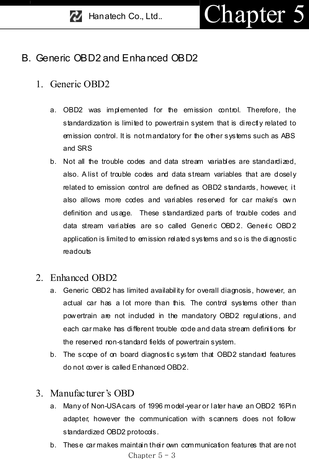
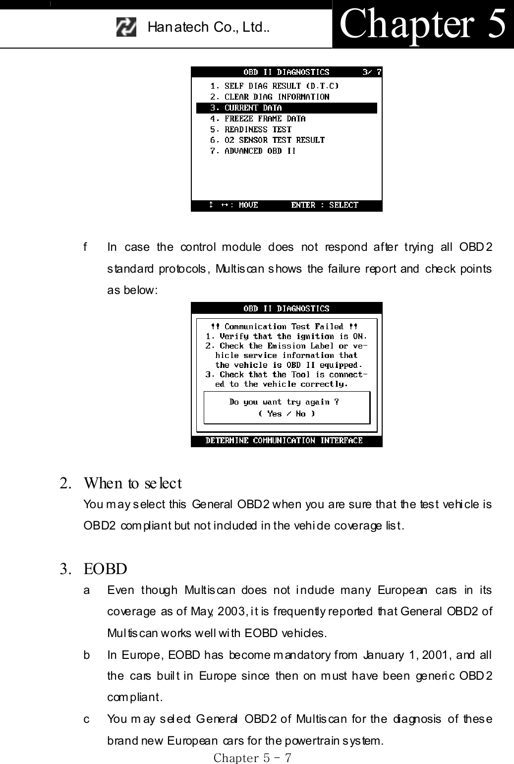
![Han atech Co., Ltd.. Chapter 5 GjG\GTG \GIII. Multiscan and OBD2 ------------------------ A. Ge ne ric OB D 2 i n M ul ti sca n 1. General OBD2 a You will find General OBD2 category in the initial menu. b Selecting [2. Generic OBD2] will be followed by the diagnostic adapter s ugges ti on. P ress the [ENTER] key to proceed. c Multiscan then automatically tries to establish communication with the powertrain control module using standard OBD2 communication protocols in turn.](https://usermanual.wiki/Hanatech/MULTISCAN/User-Guide-415188-Page-71.png)
![USER MANUAL For Multiscan GjG\GTG ]G d When succeeded in communicating with the control module with any of these 4 standard protocols, Multiscan reports the successful establishment of communication and waits for your command to com mence generic O BD2 diagnos is as below: e Available functions for the generic OBD2 system is listed as shown below:](https://usermanual.wiki/Hanatech/MULTISCAN/User-Guide-415188-Page-72.png)
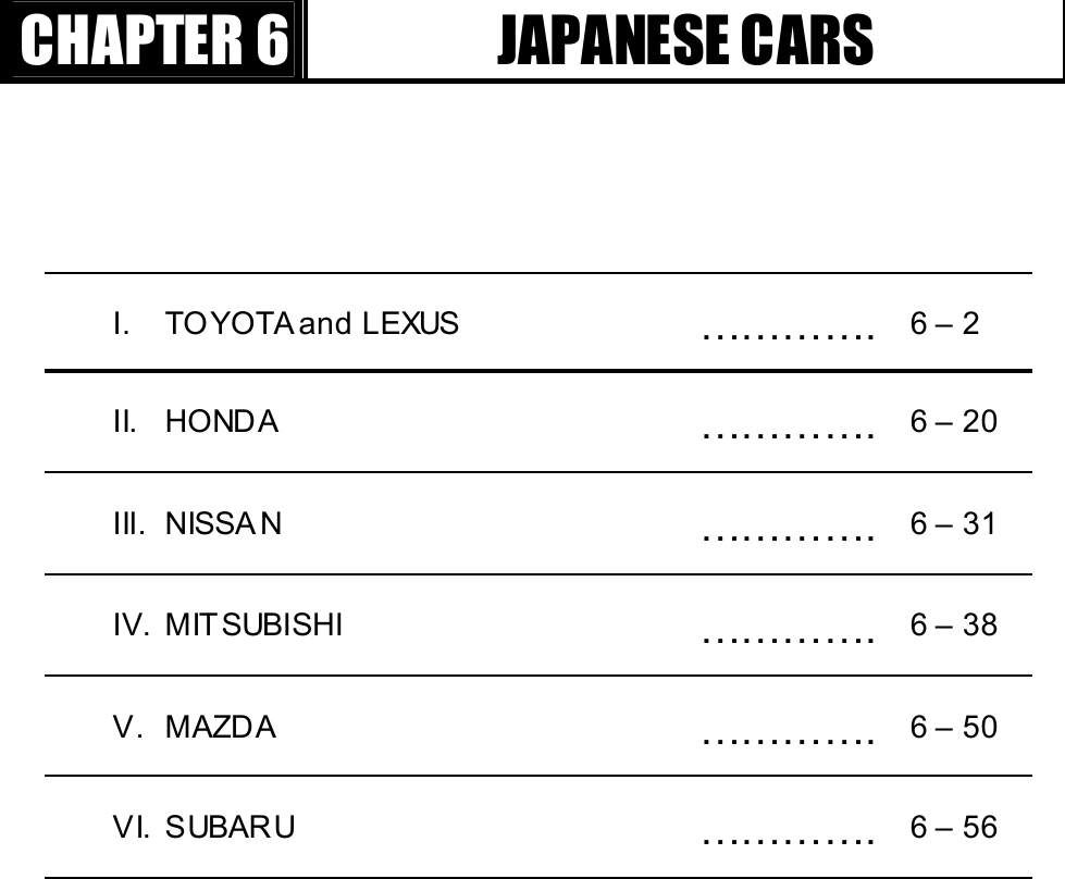
![Han atech Co., Ltd. Chapter 6 GjG]GTG XGJapanese Cars -Multiscan software package for Japanese cars is provided as a part of 128MB built-in flash m em ory. -The Japanese car package contains a set of software comprising of the following s oftw are groups. 9 TOYOTA / LEXUS USA 9 HONDA 9 NISSAN 9 MITSUBISHI 9 MAZD A 9 SUBARU 9 SUZUKI 9 ISUZU 9 Generi c OBD2 -Loading software Select [1.SCAN] from the initial function selection, select Japanese cars, then the lis t of Japanes e car makes will f ollow. The detailed m enu s el ection queries will guide you to the correct diagnostic readouts.](https://usermanual.wiki/Hanatech/MULTISCAN/User-Guide-415188-Page-75.png)
![USER MANUAL For Multiscan GjG]GTG YGI. TOYOTA and LEXUS ----------------------- Toyota and Lexus cars share the same scanner communication methods from a scanner’s viewpoint. Multiscan does not separate Toyota and Lexus in the car make menu because the detailed menu selection procedure and other features are exactly same for both marques. You can select either Toyota or Lexus in the next step. This chapter covers Toyota cars. You can also refer to this section for diagnosing Lexus cars. A. Menu Selection Toyota software of Multiscan follows the exactly same menu selection procedure as the m anufacturer’s original equipment. 1. Select TOYOTA/LEXUS Sel ect TO YO TA / LEXU S from the car make menu.](https://usermanual.wiki/Hanatech/MULTISCAN/User-Guide-415188-Page-76.png)
![Han atech Co., Ltd. Chapter 6 GjG]GTG ZG2. Select Model Name You can select between Toyota and Lexus at this stage. Toyota non-USA version is applicable to all Toyota cars outside N orth Am erica. It covers 32 di fferent model vari ants . 3. Select model cod e You have to s el ect the exact m odel code of the vehicle model (i.e. MCV10, MCV20, SXV10 and SXV11 for Camry) Each model code represents a significant difference in overall system from other model codes .](https://usermanual.wiki/Hanatech/MULTISCAN/User-Guide-415188-Page-77.png)
![USER MANUAL For Multiscan GjG]GTG [G4. Select model ye ar and other detailed model specifications Multiscan may ask for your selection for a few more steps including model year, manufacturing plant and the existence of O2 sensor or immobilizer system to specify the exact vehicle details for precise and accurate results. G](https://usermanual.wiki/Hanatech/MULTISCAN/User-Guide-415188-Page-78.png)
![Han atech Co., Ltd. Chapter 6 GjG]GTG \GB. Why so complicated The flow chart shows the menu selection procedure presented above for Camry as an exampl e. Many of aftermarket scanners have a very simple selection procedure for Toyota cars by only s electi ng the di agnos ti c adapter type. Indonesian Tamaraw and Lexus RX300 are considered same for these scanners. However, the Toyota OE tool has a very detailed vehicle selection procedure up to 5 or 6 steps. The selection procedure of Multiscan is also designed to provide reliable and diversifi ed diagnosis at OE tool level for each specific vehicle.](https://usermanual.wiki/Hanatech/MULTISCAN/User-Guide-415188-Page-79.png)
![USER MANUAL For Multiscan GjG]GTG ]G1. The difference of Toyota from the other Japanese cars Japanese cars with the exception of Toyota and Nissan have ID check system. A scanner communicates with an ECM to get the ECM ID number to identify the test vehicle. Then automatically determines the appropriate communication protocol accordingly. However, Toyota has no such ID check system. To get the correct response, it is absolutely necess ary to let the s canner know which car it is going to talk to. Each vehi cle m odel code has different types of engine and control s yst em. Even the number of sensors is different. To get full information that the vehicle ECM transmits , the m odel sel ection m us t be as speci fi c as possibl e. If a scanner starts communicating with the ECM after simply selecting the adapter, the best result you can get is limited data for the generic items that are commonly found in all Toyota cars.](https://usermanual.wiki/Hanatech/MULTISCAN/User-Guide-415188-Page-80.png)
![Han atech Co., Ltd. Chapter 6 GjG]GTG ^G2. How to get the detailed specifications a Model Code (Chass is number) O pen the engine hood and fi nd the m odel code stamped i nto the vehicl e specification tag, attached to firewall on the driver’s side. b Model year and manufacturing plant Model year and manufacturing plant information is contained in the Vehicle Identification Number. Refer to the manufacturer’s manual book for the details of VIN translation c Equipped System Some models may require you to confirm the existence of a certain system like immobilizer or traction control. You can check this from the warning lamps displayed in the dash panel right after turning the ignition key ON. 3. [33. Others] You will find this category in the end of the Toyota vehicle model list. You may select this when you cannot find the model name in the list or when you do not want to make selections for all the details. Only the adapter type selection menu will follow, and then Multiscan will begin to communicate with the ECM. As mentioned above, it will work just like an ordinary aftermarket tool does, and limited data for the common generic items will be available in this mode.](https://usermanual.wiki/Hanatech/MULTISCAN/User-Guide-415188-Page-81.png)
![USER MANUAL For Multiscan GjG]GTG _G4. Incorrect Ad apter a No match in the list Despite detailed vehicle selection procedure of Multiscan, you may encounter a situation where you cannot find the correct vehicle details in the list. If you s elect a similar vehi cl e model code or other details from the menu, an incorrect adapter may be suggested. For example, when you select AB-CD1 model code while the actual vehicle is AB-CD2 which is not included in the list, Multiscan may ask you to use 17 pin rectangular adapter even though the vehicle has the 17 pin semi-circular adapter. The communication may fail in this case. You are recommended to select [33. Others] to test the car in generic mode. b Mul tiple adapters If Multis can sugges ts to use a diagnostic adapter that is different f rom the one that you found in the car, the suggested adapter may be found elsewhere in the car. Some Japanese cars have m ultiple DLC adapters, and generally each of them covers different systems. R efer to the adapter location maps below, and check the car for the suggested adapter.](https://usermanual.wiki/Hanatech/MULTISCAN/User-Guide-415188-Page-82.png)
![Han atech Co., Ltd. Chapter 6 GjG]GTG `GC. Func tio ns 1. 17 Pin Rectangular and Semi-Circular Adaptera Diagnostic Trouble Code -D TC readout is provi ded i n Flash code pulse signals for all s ys tems when usi ng t his adapter. -This old communication type does not allow bi-directional communication between the scanner and the ECM. ECM simply transmits the slow pulse signal when the appropriate DLC terminal is grounded. b DTC Erase -Faul t code erase by a s canner is not available f or t he pulse signal type communication. -You m ust remove the (-) battery terminal to clear the fault codes. Removing the battery terminal will get rid of all inform ation contained in the car stereo and other electronic devices. And it may not effectively erase the fault codes in some cars. Refer to the original repair manual for further information. c Data Stream -Data Stream / Service Data / Live Data is supported for Engine only for this type of adapter.](https://usermanual.wiki/Hanatech/MULTISCAN/User-Guide-415188-Page-83.png)
![USER MANUAL For Multiscan Gj G]G TGXWGd Supported systems -Rectangular Adapter: Generally only Engine and SRS systems are s upported with this t ype of adapter. For the other systems such as ABS, TCS and Cruise Control, only the flash code manual reading is available by counting the relevant Malfunction Indication Lamp blinking when the adapter is connected to the vehicle side DLC. -Semi-Circular Adapter: When the vehicle has 17 Pin Semi-Circular adapter, all systems including Engine and SRS are supported through this adapter. 2. 16 Pin OBD2 Adap ter a Diagnostic Trouble Code -Fault code read and erase are both available when using the OBD2 adapter -Neither manual flash code reading nor battery terminal removal is necessary for code read and erase. b Data Stream -Service data / Data stream / Live data is available for most systems -Suspension and Cruise control systems of a few models may s upport D TC pulse signal onl y. Data s tream is not available for these exceptional models. c Actuation test -Actuation test is available for vari ous s ys tem s when usi ng this adapter.](https://usermanual.wiki/Hanatech/MULTISCAN/User-Guide-415188-Page-84.png)
![Han atech Co., Ltd. Chapter 6 Gj G]G TGXXGD. Diagnostic Adapter Location The DLC adapter location drawings are purely from the experience of Hanatech and provided for your reference only. The drawings are based on Right Hand Drive cars, therefore, you m ay have to consider the mirror image for any Left Hand Drive cars. You can view these drawings on the Multiscan screen by selecting [3.Connector Location] after selecting [2. Toyota / Lexus] from the car make list. 17 Pin Rectangular Adapter 16 Pin OBD2 Adapter 17P Semi-Circular Adapter 17 Pin Rectangular Adapter](https://usermanual.wiki/Hanatech/MULTISCAN/User-Guide-415188-Page-85.png)
![USER MANUAL For Multiscan Gj G]G TGXYG17 Pin Rectangul ar Adapter 17 Pin Rectangul ar Adapter 17 Pin Rectangular Adapter 17 Pin Rectangular Adapter](https://usermanual.wiki/Hanatech/MULTISCAN/User-Guide-415188-Page-86.png)
![HANA TECH CO., LTD. Chapter 6 Gj G]G TGXZGE. Vehicle Coverage Refer to the following coverage list. (In Alphabetic order) TOYOTA MODEL CODE Supported System 4RUNN ER KZN185 RZN180 RZN185 VZN130 VZN180 VZN185 ENGINE CONTROL SR S AIR BAG ANTI LOC K BRAKE SYSTEM POWERTRAIN CONTROL MODULE I MMOB ILISER 99L.O -- SRS AIRBAG AVALON MCX10 MCX20 POWERTRAIN CONTROL MODULE EC T ANTI LOC K BRAKE SYSTEM TRACTION CONTROL SYSTEM I MMOB ILISER CR UISE CONTROL SYSTEM SR S AIR BAG AVEN SIS AT200 AT221 CT220 ST220 AZT220 CDT220 ZZT220 ZZT221 POWERTRAIN CONTROL MODULE I MMOB ILISER SR S AIR BAG ANTI LOC K BRAKE SYSTEM CAMRY MCV10 MCV20 SXV10 SXV11 SXV20 VSV10 POWERTRAIN CONTROL MODULE EC T CR UISE CONTROL SYSTEM, I MMOB IL ISER, SR S AIR BAG ANTI LOC K BRAKE SYSTEM CARINA AT190 AT191 CT190 ST919 ENGINE CONTROL I MMOB ILISER SR S AIR BAG](https://usermanual.wiki/Hanatech/MULTISCAN/User-Guide-415188-Page-87.png)
![USER MANUAL For Multiscan Gj G]G TGX[GCELICA AT180 AT200 ST182 ST184 ST185 ST202 ST204 ST205 ZZT230 ZZT231 POWERTRAIN CONTROL MODULE, I MMOB ILISER SR S AIR BAG ANTI LOC K BRAKE SYSTEM CENTURY GZG50 ENGINE CONTROL AIR SU SPENSION, CR UISE CONTROL SYSTEM I MMOB ILISER SR S AIR BAG, BODY C ONTROL COASTER BB50 BB58 RZB40 RZB50 POWERTRAIN CONTROL ANTI LOC K BRAKE SYSTEM CONDOR LF6X,8X RZF80 RXF85 ENGINE CONTROL I MMOB ILISER COROLLA AE100 AE101 AE102 AE103 AE110 AE111 AE112 AE115 AE92 CE110 EE101 EE104 EE111 CDE110 NZE120 NZE121 WZE110 ZZE111 ZZE112 ZZE121 ZZE122 POWERTRAIN CONTROL MODULE I MMOB ILISER SR S AIR BAG ANTI LOC K BRAKE SYSTEM EMPS](https://usermanual.wiki/Hanatech/MULTISCAN/User-Guide-415188-Page-88.png)
![HANA TECH CO., LTD. Chapter 6 Gj G]G TGX\GCORONA AT190 AT210 AT220 CT220 ST171 ST191 ST210 ST220 POWERTRAIN CONTROL MODULE ANTI LOC K BRAKE SYSTEM I MMOB ILISER SR S AIR BAG CRESSIDA -- ENGINE CONTROL ANTI LOC K BRAKE SYSTEM CR UISE CONTROL SYSTEM EC T CROWN GS151 JZS133 JZS155 JZS175 POWERTRAIN CONTROL MODULE CR UISE CONTROL SYSTEM ANTI LOC K BRAKE SYSTEM VSC , EC T, SR S AIR BAG AIR CONDITIONING SYSTEM I MMOB ILISER BODY1/2/3, D/P DOOR , SLIDE ROOF, TILT & TELESCO, METER, COMBINATION SWITCH DYNA RZU100 BU213 BU223 XZU300 XZU320 XZU330 XZU340 XZU342 XZU 4XX POWERTRAIN CONTROL MODULE ANTI LOC K BRAKE SYSTEM](https://usermanual.wiki/Hanatech/MULTISCAN/User-Guide-415188-Page-89.png)
![USER MANUAL For Multiscan Gj G]G TGX]GHIACE LH103 LH114 LH125 LXH12,22 LXH18,28 RCH12 RCH13 RCH18 RCH19 RCH22 RCH23 RCH28 RZH102 RZH103 RZH105 RZH109 RZH112 RZH113 RZH115 RZH119 RZH125 RZH135 RZH153 LH162 LH172 LH174 LH184 RCH29 RZH155 ENGINE CONTROL, POWERTRAIN CONTROL MODULE, SRS AIR BAG, IMMOBILISER LAND CRUISER FZ75 FZJ80 FZJ100 FZJ105 FZJ71,74 FZJ73 HDJ100 HDJ80 HZJ105 HZJ80 KDJ90,95 KJZ90,95 RZJ90 RZJ95 UZJ100 VZJ90,95 POWERTRAIN CONTROL MODULE AH C ANTI LOC K BRAKE SYSTEM I MMOB ILISER SR S AIR BAG CR UISE CONTROL SYSTEM BODY POWER SEAT CONTROL SYSTEM TILT & TELESCO MIRROR](https://usermanual.wiki/Hanatech/MULTISCAN/User-Guide-415188-Page-90.png)
![HANA TECH CO., LTD. Chapter 6 Gj G]G TGX^GHILUX LN14X LN15X LN16X LN17X LN19X RN 106 RN 110 RN85 RXN142 RZN144 RZN149 RZN147 RZN148 RZN154 RZN168 RZN169 RZN173 RZN174 RZN193 RZN194 KZN165 KZN190 POWERTRAIN CONTROL MODULE I MMOB ILISER SR S AIR BAG KIJAN G KF72 KF82 RZF71 RZF81 ENGINE CONTROL LITEACE CR42 KR42 SR40 YR22,29 POWERTRAIN CONTROL MODULE SR S AIR BAG I MMOB ILISER MR2 SW20 ZZW30 POWERTRAIN CONTROL MODULE SR S AIR BAG I MMOB ILISER ANTI LOC K BRAKE SYSTEM EH PS SEQUENTIAL MT PASEO EL54 ENGINE CONTROL SR S AIR BAG I MMOB ILISER PICNIC CXM10 SXM10 POWERTRAIN CONTROL I MMOB ILISER SR S AIR BAG PREVIA TCR10,11 TCR20,21 ACR30 CLR30 POWERTRAIN CONTROL MODULE SR S AIR BAG I MMOB ILISER ANTI LOC K BRAKE SYSTEM CRUISE CONTROL MODULE](https://usermanual.wiki/Hanatech/MULTISCAN/User-Guide-415188-Page-91.png)
![USER MANUAL For Multiscan Gj G]G TGX_GPRIUS -- POWERTRAIN CONTROL MODULE EMPS ANTI LOC K BRAKE SYSTEM SR S AIR BAG CR UISE CONTROL SYSTEM I MMOB ILISER RAV4 SXA10,11 ACA20,21 ZCA25,26 POWERTRAIN CONTROL MODULE SR S AIR BAG ANTI LOC K BRAKE SYSTEM I MMOB ILISER RAV4 EV -- SR S AIR BAG SOLUNA(AFC) AL50 ENGINE CONTROL SPACI O AE111 ENGINE CONTROL SR S AIR BAG ANTI LOC K BRAKE SYSTEM STARLET EP81 EP82 EP91 ENGINE CONTROL I MMOB ILISER SR S AIR BAG SU PR A JZA80 ENGINE CONTROL EC T ANTI LOC K BRAKE SYSTEM CR UISE CONTROL SYSTEM SR S AIR BAG TRACTION CONTROL SYSTEM TAM AR AW KF80 RZF81 ENGINE CONTROL, TERCEL EL51 EL53 ENGINE CONTROL SR S AIR BAG UN SER -- EN GINE CONTROL YAR IS ECHO SCP10 NCP10 NC P11 NCP12 NCP13 NCP20 NCP21 NCP22 POWERTRAIN CONTR OL SYSTEM EMPS ANTI LOC K BRAKE SYSTEM SR S AIR BAG I MMOB ILISER FREE-TRONIC STOP&GO ZACE KF60 KF80 RZF84 RZF85 ENGINE CONTROL SR S AIR BAG](https://usermanual.wiki/Hanatech/MULTISCAN/User-Guide-415188-Page-92.png)
![HANA TECH CO., LTD. Chapter 6 Gj G]G TGX`GLEXUS MODEL CODE Supported Systems ES300 MCV20 VC V10 POWERTRAINEMS, ABS, CC S, IMM, SRS GS 300 JZS147 JZS1 60 POWERTRAIN, ABS/VSC, CCS, A/C, IMM, SRS, BODY, BODY2, DOOR (D, P, RR, RL), SEAT, SLIDE ROOF, TILT&TELESCO, METER GS 430 U ZS161 POWERTRAIN, ABS/VSC, CCS, A/C, IMM, SRS, BODY, BODY2, D OOR (D, P, RR, RL), SEAT, SLIDE ROOF, TILT, METER , STEERING PAD IS200 GXE10 POW ER TRAIN, ABS, CCS, A/ C , IMM, SRS , BO D Y, METER , TDS LS400 UCF10 UCF20 POWERTRAIN, ECT, AIR SUS, ABS, TRACTION, CCS, A/C , IMM, SR S, SRS SID E LS430 UCF30 POW ER TRAIN, AI R SU S, ABS/VSC , CC S, A/C , I MM, SR S , GATE W AY, B O D Y ( 1 ,2 ,3 , 4 ,5 ), D OOR (D , P, RR , R L ) , SEAT(D , P, ``RR, RL), REAR SEAT S/W, SLIDE ROOF, TILT, METER, COMBI S/W, STEERI NG PAD, TDS , CLEARANCE SONAR, RAIN SENSOR LX470 UZJ100 POWERTRAIN, AHC, ABS/TRACTION/VSC, CCS, IMM, SRS, BOD Y, SEAT, TILT/TELESCO, MIRROR RX300 MCU15 POWERTRAIN, ABS/TRAC/VSC, CC S, A/C, IMM, SRS, BODY, DOOR(D, P, RR, RL), SLIDE ROOF, METER, TDS SC430 UZZ40 POWERTRAIN, TIRE PRESSUR E WARNIN G, ABS/VSC , CCS, A/C, IMM, SRS.GATEWAY, BODY (2, 3, 4, 5), DOOR (D , P), SEAT (D , P), RETRACTABLE HARDTOP, TILT, METER, COMBI S/W, STEERING PAD, TDS](https://usermanual.wiki/Hanatech/MULTISCAN/User-Guide-415188-Page-93.png)
![USER MANUAL For Multiscan Gj G]G TGYWGII. HONDA ---------------------------------------- A. Features of Honda S/W 1. Communicatio n Start-up a Honda has the ECM ID check system. Complicated menu selection procedure as in Toyota is not necessary for Honda cars. b The user is simply required to check the adapter type of the vehicle and to select the adapter and the desired system to test. c Then Multiscan automatically begins to talk to the ECM to identify the system ID and determines its communication details according to the response from the ECM.](https://usermanual.wiki/Hanatech/MULTISCAN/User-Guide-415188-Page-94.png)
![HANA TECH CO., LTD. Chapter 6 Gj G]G TGYXG2. Performancea Multiscan HONDA software is applicable to all Honda cars regardless of regional market and covers up to 4,000 different system IDs when counting the Engine control system only. Total 7,000 IDs are included in the database for all Honda car systems. b Multiscan Honda software provides original equipment level reliability and accuracy for Honda cars up to 2003 model year. 3. Difference a It is very di fficult and time consuming to analyze al l the s ys tem IDs for Honda cars. Most scanners provide only the limited readouts that are commonly available in all Honda cars. Honda Civic and Acura Legend are considered same for these scanners. b Multiscan identifies each ECM version and provides the most optimized and precise diagnostic inform ation of OE tool level.](https://usermanual.wiki/Hanatech/MULTISCAN/User-Guide-415188-Page-95.png)
![USER MANUAL For Multiscan Gj G]G TGYYGB. Menu Selection1. Select HONDA/AC URA Select HONDA /ACURA from the car make menu. 2. Select the adapter type Search for the diagnostic connector in the car referring to the connector location drawings hereinafter and select the connector type found.](https://usermanual.wiki/Hanatech/MULTISCAN/User-Guide-415188-Page-96.png)
![HANA TECH CO., LTD. Chapter 6 Gj G]G TGYZG3. Select Test System Select the system you want to test.](https://usermanual.wiki/Hanatech/MULTISCAN/User-Guide-415188-Page-97.png)
![USER MANUAL For Multiscan Gj G]G TGY[GC. Adapters 1. 2-Pin Connector a 2-pin adapter is generally found together with the 3-pin adapter, however, some old cars may have this adapter only. b Live data (Data stream ) is not available for all systems when using this 2-pin adapter. Only reading the flash signal in the dash panel is available with this adapter and bi-directional serial communication with a scanner is not available. Therefore, it supports the Trouble Code read function only. 2. 3 Pin connecto r a 3-pin adapter is generally found together with the 2 -pi n ada pte r, how eve r, som e ca rs m a y have this adapter only. b Live data is available but some ABS and SRS systems may support Trouble Code pulse signal onl y. 3. 2 + 3 Pin connector a 2-pin and 3-pin adapters are generally found together. In this case,](https://usermanual.wiki/Hanatech/MULTISCAN/User-Guide-415188-Page-98.png)
![HANA TECH CO., LTD. Chapter 6 Gj G]G TGY\Geach adapter is assigned to different systems in the car. b You are recomm ended to try to tes t the s ys tem wi th 3-pin adapter f irs t, and then try with 2-pin adapter in the event communication using 3-pin adapter fails. 4. 16 Pin connecto r 16-pin adapter equates to the OBD2 s tandard adapter. Fault Code read and erase, and live data is supported for all systems.](https://usermanual.wiki/Hanatech/MULTISCAN/User-Guide-415188-Page-99.png)
![USER MANUAL For Multiscan Gj G]G TGY]GD. ECM RESET function-Foll owing ECM repl acem ent, faul t code erasi ng or when you feel the necessity to reset ECM adaptation due to poor engine perform ance, you can activate this function. -It cleans up the ECM memory and makes the ECM ready for self-adaptation. 1. Select ECM RES ET You may select this function when you select the ENGINE CONTROL system from the SELECT DEVICE menu that follows the adapter type selection. 2. A fter Reset After the resetting, ECM needs some time to relearn the idling condition and finalize self-adaptation. Start and idle the car for more than 5 minutes after warm -up. Otherwise poor engine performance will result.G](https://usermanual.wiki/Hanatech/MULTISCAN/User-Guide-415188-Page-100.png)
![HANA TECH CO., LTD. Chapter 6 Gj G]G TGY^GGE. Adapter location a The location drawings are purely from the experience of Hanatech and provided for your reference only. b The drawings are based on Right Hand Drive cars, therefore, you may have to consider the mirror image for any Left Hand Drive cars. c You can view these drawings on the Multiscan screen by selecting [3.Connector Location] after s electi ng [3. HOND A] from the car make list.](https://usermanual.wiki/Hanatech/MULTISCAN/User-Guide-415188-Page-101.png)
![USER MANUAL For Multiscan Gj G]G TGY_GF. Vehicle Coverage -The vehicle coverage listed below is limited to the cars that supports live data (Data stream / Service data) with 3-pin or 16-pin adapter -Older cars with 2-pin adapter are not included. JAPAN ESE DOMESTIC Model Name From Until Accord 1994 2002 Acty 1994 2002 As cot 1994 1997 Avancier 2000 2002 Capa 1998 2001 Civic 1992 2002 Civic Coupe 1993 1996 Civic 5Door 2001 2002 Civic Hybrid 2002 2002 Stream 2001 2002 CR-V 1996 2002 CR-X 1992 1996 Domani 1993 2000 Fit 2002 2002 HR-V 1999 2002 Insight 2000 2002 Inspire 1995 2000 Ins pire V6 1995 2003 Integra 1992 2002 Integra SJ 1996 2000 Lagreat 1999 2002 Legend 1996 2002 Life 1997 2002 Logo 1997 2001 Mobilio 2002 2002 NSX 1995 2002 Odyssey 1995 2002 Odyssey V6 1998 2002 Orthia 1996 2000 Partner 1996 2000 Prelude 1992 2001 Rafaga 1994 1997 S2000 1999 2002 Saber 1995 2003 S-MX 1997 2001 Step Wagon 1996 2002 That's 2002 2002 Today 1993 1998 Toreno 1998 2002 Vamos 1999 2002 Z 1999 2000](https://usermanual.wiki/Hanatech/MULTISCAN/User-Guide-415188-Page-102.png)
![HANA TECH CO., LTD. Chapter 6 Gj G]G TGY`GNORTH AMERICAN Model Name From Until Accord 1994 2002 Accord V6 1995 2002 Acura 1.6EL 1997 2000 Acura 1.7EL 2001 2002 Acura 2.2CL 1997 1997 Acura 2.3CL 1998 1999 Acura2.5TL 1995 1998 Acura 3.0CL 1997 2000 Acura 3.2CL 2001 2003 Acura 3.2TL 1995 2003 Acura 3.5RL 1996 2002 Acura MD-X 2001 2002 Acura RSX 2002 2002 Civic 1992 2002 Civic Coupe 1993 2002 Civic Hybrid 2002 2003 CR-V 1997 2002 CR-X 1992 1997 Insight 2000 2002 Integra 1992 2001 NSX 1995 2002 O dyss ey 1995 2002 Pil ot 2003 2003 Prelude 1992 2001 S2000 2000 2002 EUROPEAN Accord 1994 2002 Accord V6 1998 2002 Civic 1992 2002 Civic Aero 1998 2000 Civic Coupe 1994 2002 Civic 5Door 1995 2001 Stream 2001 2002 CR-V 1997 2002 CR-X 1992 1997 HR-V 1999 2002 Insight 2000 2002 Integra 1998 2002 Jazz 2002 2002 Legend 1996 2002 Logo 1999 2000 NSX 1995 2002 Prelude 1992 2001 S2000 2000 2002 Shuttle 1995 1999](https://usermanual.wiki/Hanatech/MULTISCAN/User-Guide-415188-Page-103.png)
![USER MANUAL For Multiscan Gj G]G TGZWGGENER AL Accord 1994 2002 Accord V6 1995 2002 Acura 2.5TL 1995 1998 Acura 3.2TL 1996 2002 Acura 3.5TL 1996 2002 Ci ty 1996 2001 Civic 1992 2002 Civic Coupe 1994 2002 Civic 5Door 1997 2002 Stream 2001 2002 CR-V 1996 2002 CR-X 1992 1997 FIT 2002 2002 HR-V 1999 2002 Insight 2001 2002 Ins pire V6 1999 2000 Integra 1992 2002 Jazz 2002 2002 Legend 1996 2002 Logo 1999 2000 NSX 1995 2002 O dyss ey 1995 2002 O dyss ey V6 2000 2002 Pil ot 2003 2003 Prelude 1992 2001 S2000 2000 2002 Step Wagon 1998 2003 Vigor 1995 1998](https://usermanual.wiki/Hanatech/MULTISCAN/User-Guide-415188-Page-104.png)
![HANA TECH CO., LTD. Chapter 6 Gj G]G TGZXGIII. NISSAN ---------------------------------------- A. Features of Nissan S/W 1. Communicatio n Start-up a Nissan has neither the ECM ID check system like Honda nor the compli cated menu selection system like Toyota. b After system selection, the scanner sends a set of commands to the ECM for all data listings available within the vehicle, and then com municates with the ECM for the avail able items only.](https://usermanual.wiki/Hanatech/MULTISCAN/User-Guide-415188-Page-105.png)
![USER MANUAL For Multiscan Gj G]G TGZYGc The system check commands and communication details have been constant without change for both 14-pin and 16-pin diagnostic adapters. Therefore, a scanner does not need to know the ID number or the detailed vehicle specification. Simply select the adapter type and the s canner will comm uni cate with the ECM for all avail able items. 2. Performance a Mul tis can NI SSAN s oftware is appli cable to all Niss an cars up to 2002 model year as of May 2003. b System Coverage Engine, Transmission, ABS, SRS, IVMS (In Vehicle Multiple System): Body control HICAS (High Intelligence Control Active Steering) AS CD (Automatic Speed Control Device): Cruise control. 3. Menu Se lection a Select NISSAN Select NISSAN / INFINITI from the car make menu.](https://usermanual.wiki/Hanatech/MULTISCAN/User-Guide-415188-Page-106.png)
![HANA TECH CO., LTD. Chapter 6 Gj G]G TGZZGb Select the adapter type Find the diagnostic connector in the car referring to the connector location drawings hereinafter and select the connector type found. c Select test system Select the system you want to test Mul tis can alw ays shows 7 s ys tems for sel ection i n the m enu. However, it doesn’ t m ean that the car has all the systems and that all of the systems are available for communication with Multiscan. Select any control module from the menu as illustrated above, then Multiscan will try to talk to the selected control module. If the control module responses properly, then Multiscan shows the detailed function listings for the control module. If it shows the “Communication Error” message, it is considered the vehicle has no such a system or the control module does not support scanner communication.](https://usermanual.wiki/Hanatech/MULTISCAN/User-Guide-415188-Page-107.png)
![USER MANUAL For Multiscan Gj G]G TGZ[GB. Adapters a 14-pin and 16-pin adapters are being used for Nissan cars. In North America, Nissan cars of 1995 model year or later usually have 16-pin OBD2 adapter while the older cars have 14-pin adapter. Some cars released around 1996 may have both connectors. b Outside North America, late models of Nissan continue to use the 14-pin adapter in some countries, therefore, the application of each adapter is yet to be confirmed. Refer to the connector location hereinafter, and search for the adapter first to make a correct selection. C. IV MS (als o appli cabl e to HICAS and ASC D s ystems)1. System Me nu a Mul tis can always s hows the IVMS in the s ystem s election m enu. However, it doesn’ t conclude that the car has the s ys tem or i t is availabl e for comm uni cation with Mul tiscan.](https://usermanual.wiki/Hanatech/MULTISCAN/User-Guide-415188-Page-108.png)
![HANA TECH CO., LTD. Chapter 6 Gj G]G TGZ\Gb Select IVMS from the system menu as shown above, then Multiscan will attempt communication to the IVMS control module. If the car has the IVMS system, then Multiscan will show you the IVMS item listing. c If the “Com municati on Error” mess age is displayed, the s ys tem is ei ther not fitted to the vehicle or does not feature self-diagnos tics . 2. IVMS items a Once the communication is established, Multiscan lists all 22 IVMS items, however, in the same manner, it doesn’t mean that communication with each of 22 items is supported by the IVMS m odule. b Select an IVMS item from the IVMS menu, then Multiscan will communicate to the IVMS control module to check if the item is supported. If the item is supported, then Multiscan will show the available functions with the item, in example, live data and actuation test. c If the “Communicati on Error” mess age is displayed, it is probable that the item is not supported by the IVMS module.](https://usermanual.wiki/Hanatech/MULTISCAN/User-Guide-415188-Page-109.png)
![USER MANUAL For Multiscan Gj G]G TGZ]GD. Adapter location -The location drawings are purely from the experience of Hanatech and provided for your reference only. The drawings are based on Right Hand Drive cars, therefore, you may have to consider the mirror image for any Left Hand Drive cars. -You can view these drawings on the Multis can s creen by s electi ng [3.Connector Location] after selecting [4. NISAN] from the car make list.](https://usermanual.wiki/Hanatech/MULTISCAN/User-Guide-415188-Page-110.png)
![HANA TECH CO., LTD. Chapter 6 Gj G]G TGZ^GE. Vehicle Coverage -Since the communication protocol for Nissan cars is quite stable with few vari ations , vehi cl e coverage is meaningless to lis t in detail as for Toyota or Honda. -The followings are the examples of Nissan models that Hanatech or its worldwide partners have tested and confirmed its successful communication 200SX, 240SX, 300ZX, ALTIMA, AXXESS, FAIRLADY, FRONTIER, MAXIMA, MIN I VAN , N X, PATH FIND ER, PICKU P, PULSAR N X, QUEST, SEN TRA, SKYLINE, STANZA, XTERRA, CEFIRO, SILVIA, TINO, 240SE, MAR C H, VERI TA, AL MER A, PR I MER A, TERR AN O II , PATR OL GR, etc.](https://usermanual.wiki/Hanatech/MULTISCAN/User-Guide-415188-Page-111.png)
![USER MANUAL For Multiscan Gj G]G TGZ_GIV. MITSUBISHI ---------------------------------- A. Fea tures o f Mits ubis hi S /W 1. Communicatio n Start-up a Mi ts ubishi has the ECM ID check s ys tem sim ilar to Honda. Complicated menu selecting procedure as for Toyota is not necessary for Mitsubishi cars. b The user is simply required to check the adapter type of the vehicle and to select the adapter and the desired system to test. Then Multiscan automatically begins to talk to the ECM to identify the ID number and determines its communication details according to the response. c One thing different from Nissan is that the communication speed varies a lot, therefore, Multiscan checks the speed of the incoming signal from an ECM and determines communication speed automatically thereupon.](https://usermanual.wiki/Hanatech/MULTISCAN/User-Guide-415188-Page-112.png)
![HANA TECH CO., LTD. Chapter 6 Gj G]G TGZ`G2. Performance a Mi ts ubishi original equipment has vari ous regional versions that cover the Mitsubis hi cars in each regional m arket. b Mul tis can Non-US A vers ion compris es of Japanese domes ti c, Aus tralian, Mal aysian and European regional versions . c Mitsubishi software covers up to 1,500 different system IDs when counting the Engine control system only. Total 2,500 IDs are included in the database for all Mitsubishi car systems. d Multiscan Mitsubishi software provides original equipment level reliability and accuracy for Mitsubishi cars up to 2002 model year. B. Ge tting Started 1. Select Mitsub ishi Select MITSSUB ISHI from the car m ake menu.](https://usermanual.wiki/Hanatech/MULTISCAN/User-Guide-415188-Page-113.png)
![USER MANUAL For Multiscan Gj G]G TG[WG2. Select the adapter typeSearch for the diagnostic connector in the car referring to the connector location drawings hereinafter and s elect the connector type you found. 3. Select test systemSelect the system you want to test](https://usermanual.wiki/Hanatech/MULTISCAN/User-Guide-415188-Page-114.png)
![HANA TECH CO., LTD. Chapter 6 Gj G]G TG[XGC. Adapters 1. 12-Pin Connector a 12-pin adapter is widely used for all Mitsubishi cars of OBD generation 1. b It provides the same level of data readings as the OBD2 adapter. Read / Erase of fault codes, actuation test and data stream are available for all systems except ETACS. c This adapter is also used for Korean Hyundai and Malaysian Proton cars. Pin number Assigned System 1 Engine – MPI 2 Steering - 4WS 3 Sus pension - Acti ve ECS 4 Brake – ABS 5 Cruise Control – ASC 6 Transmissi on - ELC-4AT 7 Air Conditioner - Full Auto AC 8 Air Ba g – SRS 9 ETACS: Pulse signal onl y 12 Ground](https://usermanual.wiki/Hanatech/MULTISCAN/User-Guide-415188-Page-115.png)
![USER MANUAL For Multiscan Gj G]G TG[YG2. 12+16 Pin Connectors a Many of Mitsubishi cars manufactured in mid 90`s have both the 12-pin Mitsubishi adapter and OBD2 16-pin adapter. b Many Mitsubishi control modules with MELCO system communicate using its own conventional protocol, which is not OBD2 compliant even though t he vehi cle has the O BD 2 standard adapter. c With MELCO s yst em, each pin of the OBD 2 adapter is ass igned to individual control module, therefore, when the total number of control module exceeds the number of pins, it is necessary to use additional ad apt e r to co ve r t h e e xce ssive co ntrol mo dules . d When the vehicle has both the OBD2 16-pin and Mitsubishi 12-pin adapters, the 12+16 pin dual headed adapter must be connected for proper operation. WARNING Do not use this adapter when there is only one 16-Pin OBD2 adapter or 12-Pin Mitsubis hi adapter. Us e the corres ponding s ingle adapter.](https://usermanual.wiki/Hanatech/MULTISCAN/User-Guide-415188-Page-116.png)
![HANA TECH CO., LTD. Chapter 6 Gj G]G TG[ZG3. 16 Pin connecto ra 16-pin adapter equates to the OBD2 standard adapter. Live data is supported for all systems except ETACS and some early transmissions b All systems in the control system selection menu are covered with this adapter when it is found alone in the vehicle.](https://usermanual.wiki/Hanatech/MULTISCAN/User-Guide-415188-Page-117.png)
![USER MANUAL For Multiscan Gj G]G TG[[GD. Unidentified system ID 1. System ID Check As explained herein, Multiscan automatically checks the system ID when you select a control system and sets up the communication with the control module thereupon. Multiscan Mitsubishi software contains thousands of system ID for various regional market specifications, however, it is still possible that you may encounter Mitsubishi cars of which system ID is not included in the Mul tis can softw are databas e. 2. Alternative System IDs When Multiscan finds an unknown system ID or when it cannot find the matching system ID in the database, it shows the closest system IDs for you to alternatively s elect as shown below : In the example, Multiscan found that the actual system ID E123 is not i ncl uded in the database, and it presents tw o clos est IDs of E122 and E124 for the user’s alternative selection.](https://usermanual.wiki/Hanatech/MULTISCAN/User-Guide-415188-Page-118.png)
![HANA TECH CO., LTD. Chapter 6 Gj G]G TG[\G3. Possible inco rrect values This is bas ed on the concept that t he closest s ystem IDs s hare the majority of system characteristics with the least differences. However, we cannot guarantee the accuracy of data values when choosing an alternative ID. 4. Cooperation for Update Should you encounter any of these missing IDs, please contact your local distributor with the ID numbers so that we can add them in the next software update.](https://usermanual.wiki/Hanatech/MULTISCAN/User-Guide-415188-Page-119.png)
![USER MANUAL For Multiscan Gj G]G TG[]GE. Communication Error 1. Menu Mul tis can always s hows 7 control s ys tem s in the menu as shown in the il lus tration, however, it does n’t m ean that the test vehicle has all the lis ted systems available for scanner communication. 2. Checking the existence of selected contro l systems To confirm that the selected is equipped with the electronic control module for the system you want to test, observing the warning lamp soon after turning the ignition key ON. Then let Multiscan talk to the control module first by selecting a system after connecting the correct adapter. 3. Success and FailureSuccessful communication or Unidentified ID report confirms that the system is available for scanner communication. To the contrary, in the case of communication failure, please check the following: z The vehicle does not have an electronic control module for the selected system z If the vehicle has the electronic control system: 9 Im proper adapter selection or poor contact 9 Control module or communication wiring is defective 9 Unable to establish communication with the control module due t o i n comp le te Multis can s of twa re (C on t act you r local dis trib utor)](https://usermanual.wiki/Hanatech/MULTISCAN/User-Guide-415188-Page-120.png)
![HANA TECH CO., LTD. Chapter 6 Gj G]G TG[^GF. Power supply 1. 12-pin adapter Mi ts ubishi 12-pi n adapter has no pin for power supply. You have to use the cigarette lighter power cabl e to s upply power t o Multiscan head unit when you are using this adapter for communication. 2. OBD2 adapter The OBD 2 adapter does not require external power s uppl y as 12V battery power is supplied from the adapter.](https://usermanual.wiki/Hanatech/MULTISCAN/User-Guide-415188-Page-121.png)
![USER MANUAL For Multiscan Gj G]G TG[_GG. Adapter location z The location drawings are purely from the experience of Hanatech and provided for your reference only. z The drawings are based on Right Hand Drive cars, therefore, you may have to consider the mirror image for any Left Hand Drive cars. z You can view thes e drawings on the Mul tis can s creen by s electi ng [4.Connector Location] after s electi ng [MITSUBISHI] from the car m ake l ist.](https://usermanual.wiki/Hanatech/MULTISCAN/User-Guide-415188-Page-122.png)
![HANA TECH CO., LTD. Chapter 6 Gj G]G TG[`GH. Vehicle Coverage z The communication protocol for Mitsubishi cars is quite stable with few variations. Since the communication between a scanner and control module is established not by the model name but by the system ID, knowing the exact system ID is the most important and the vehicle coverage in the list of model nam es as Toyota or Honda is almost meani ngless . z The following are the examples of Mitsubishi model names that Hanatech and its worldwide partners have tested and confirmed its successful communication 3000 GT, Carisma, Diamante, Eclipse, Expo, Galant, Lancer, L200, Mirage, Legnum, Libero, Montero, Pajero, Shogun, Space W agon, etc.](https://usermanual.wiki/Hanatech/MULTISCAN/User-Guide-415188-Page-123.png)
![USER MANUAL For Multiscan Gj G]G TG\WGV. MAZDA ---------------------------------------- A. Features of Mazda S/W 1. Communicatio n Start-up a Mazda has no ID check system like Honda or Mitsubishi. Since the communication protocol is quite simple with few variations, complicated menu selecting procedure as Toyota is not necessary, either. b The user is simply required to check the adapter type of the vehicle and to select the adapter and the desired system to test. 2. Performance a Mazda has three different communication methods: Pulse signal type for old cars, Mazda MOBD and Generic OBD2 of SAE J1850 type, and uses three types of diagnostic adapter: 6-pin Mazda/Kia adapter, 17-pin Mazda adapter and OBD2 16-pin adapter. b Only the pulse signal type Diagnostic Trouble Code reading function is](https://usermanual.wiki/Hanatech/MULTISCAN/User-Guide-415188-Page-124.png)
![HANA TECH CO., LTD. Chapter 6 Gj G]G TG\XGavailable when using 6-pin or 17-pin manufacturer’s adapter. Fault code erase and Data Stream are available only when the OBD2 16-pin adapter is used. c Multiscan Mazda software is based on the vehicles built in Japan. It may not be compatible with Mazda cars locally manufactured in other countries. B. Adapters 1. Mazda/Kia 6-pin adapter Only the pulse signal type DTC reading function for Engine control system is available when using this type of adapter. 2. Mazda 17-pin adaptera Mul tis can s upports only t he Di agnos tic Trouble Code reading function for Power train, Transmission, Airbag, ABS, Cruis e Control and Air conditioner control systems when using this type of adapter b The adapter looks the same as Toyota/Lexus Semi-circular adapter. The Mazda adapter is colored light gray for distinction from Toyota. Be careful not to apply the wrong adapter. This may cause malfunction of either vehicle control module or Multiscan.](https://usermanual.wiki/Hanatech/MULTISCAN/User-Guide-415188-Page-125.png)
![USER MANUAL For Multiscan Gj G]G TG\YG3. OBD2 16-pin adapter1) DTC read / erase and Data stream functions are available when using OBD2 16-pin adapter. 2) You can make selection among “B s eri es t rucks ” and other cars in the next step menu when choosing this adapter. 3) Powertrain, ABS, Generic Electronic and Integrated Airbag modules are available for the “B series” trucks. Only Powertrain and ABS are available for other models.](https://usermanual.wiki/Hanatech/MULTISCAN/User-Guide-415188-Page-126.png)
![HANA TECH CO., LTD. Chapter 6 Gj G]G TG\ZG4) Powertrai n m odul e comm uni cation is made by Generic OBD2 standard J1850 protocol, and the Mazda MOBD protocol is used for all other systems.](https://usermanual.wiki/Hanatech/MULTISCAN/User-Guide-415188-Page-127.png)
![USER MANUAL For Multiscan Gj G]G TG\[GC. Adapter location z The location drawings are purely from the experience of Hanatech and provided for your reference only. z The drawings are based on Right Hand Drive cars, therefore, you may have to consider the mirror image for any Left Hand Drive cars. z You can view thes e drawings on the Mul tis can s creen by s electi ng [4.Connector Location] after s electi ng [MAZDA] from the car make lis t.](https://usermanual.wiki/Hanatech/MULTISCAN/User-Guide-415188-Page-128.png)
![HANA TECH CO., LTD. Chapter 6 Gj G]G TG\\GD. Vehicle Coverage z The communication protocol for Mazda cars is very stable without variations. Since the communication between a scanner and control module is established automatically solely by selecting an adapter type without any specified vehicle model selection or system ID check, detailed vehicle coverage like Toyota or Honda is meaningless . z The following are the examples of Mazda model names that Hanatech and its worldwi de partners have tes ted and confirmed i ts success ful com munication. 323, 626, 929, MX3, MX6, Miata, Protégé, RX7, etc](https://usermanual.wiki/Hanatech/MULTISCAN/User-Guide-415188-Page-129.png)
![USER MANUAL For DCN Scanners Gj G]G TG\]GVI. SUBARU --------------------------------------- A. Features of SUBARU S/W 1. Communicatio n Start-up a SUBARU has the ECM ID check system like Honda and Mitsubishi. Complicated menu selection procedure as in Toyota is not necessary for Subaru cars. b The user is simply required to check the model year and then select the system to test. c Then Multiscan automatically begins to talk to the ECM to identify the system ID and determines its communication details according to the response from the ECM.](https://usermanual.wiki/Hanatech/MULTISCAN/User-Guide-415188-Page-130.png)
![HANA TECH CO., LTD. Chapter 6 Gj G]G TG\^G2. Performancea Multiscan SUBARU software was engineered and developed in Australia and New Zealand for the cars in this regional market where Multiscan provides more than 90% of the original equipment coverage. b Mu l tis can SU BAR U s oftwa re cove rs SU BARU ca rs from 19 94 model -year up to 2002 as of May 2003. c Subaru software is being upgraded and is scheduled to extend its coverage to 1994 or earlier model years before the end of year 2003. Please contact your local distributor and check the availability of update 3. Difference a It is very diffi cult and tim e consuming to anal yze al l the s ystem IDs for a certain car make. Most scanners provide only the limited readouts that are commonly available in all SUBARU cars. b Multiscan identifies each ECM version and provides the most optimized and precise diagnostic inform ation of OE tool level.](https://usermanual.wiki/Hanatech/MULTISCAN/User-Guide-415188-Page-131.png)
![USER MANUAL For DCN Scanners Gj G]G TG\_GB. Menu Selection1. Select SUBARU Select SUBARU from the car make menu. 2. Select Model-year Select the model year of the test vehicle.](https://usermanual.wiki/Hanatech/MULTISCAN/User-Guide-415188-Page-132.png)
![HANA TECH CO., LTD. Chapter 6 Gj G]G TG\`G3. Select Test System Select the system you want to test zGGGG GGGGGG G GGGGSG G GGGGvikG G G G SG G G hizGUGGhGGGGGGGGG SG G SG G SG G SG G G G ¡ G G G G G UGwGGGGGGGGGG GUG](https://usermanual.wiki/Hanatech/MULTISCAN/User-Guide-415188-Page-133.png)
![USER MANUAL For DCN Scanners Gj G]G TG]WGC. Adapters 1. 9 Pin Connector SUBARU 9 pin adapter is widely used for most of SUBARU cars. Trouble code read, erase and data stream are all available through this adapter. 2. 16-pin OBD2 connectorA standard adapter used for relatively new SUBARU cars. Trouble code read and erase, and Data stream are supported.](https://usermanual.wiki/Hanatech/MULTISCAN/User-Guide-415188-Page-134.png)
![HANA TECH CO., LTD. Chapter 6 Gj G]G TG]XGD. SRS airbag diagnosisIt is s aid t hat the manufacturer has designed the s ys tem without s canner communication for safety reasons. You are recommended to check the trouble codes m anuall y referring to the following inform ation. It is also recom mended NOT to test SRS sys tem when using diagnostic equipment for t he other s ys tem s s uch as Engine and Transm ission. 1. Selecting SRS a When you select [4. Airbag] from the system selection menu, Multiscan will show a message as shown below: Please note that Airbag DTC descriptions that Multiscan provides on screen are extracted from a few famous models of Subaru, roughly identified by model years. However, the DTC definitions and descriptions may differ according to the regional and vehicle detail vari atio ns . Therefore, Airbag DTC inform ation of Multiscan does not cover all Subaru cars and may be incorrect. It is always highly recommended to refer to factory m anuals for correct and detailed information.](https://usermanual.wiki/Hanatech/MULTISCAN/User-Guide-415188-Page-135.png)
![USER MANUAL For DCN Scanners Gj G]G TG]YGb Function sel ecti on menu follows when the [ENTER] key is pressed as shown below: 2. Fault code list When sel ected, Multis can shows the DTC des criptions of Subaru airbag s ys tem as s h ow n b elo w. Yo u c a n r e fe r t o t hi s l is t aft e r rea di ng th e f a ul t code(s) manually. Once again, Airbag DTC information of Multiscan does not cover all Subaru cars and may be incorrect. It is always highly recommended to refer to factory manuals for correct and detailed in formati on.](https://usermanual.wiki/Hanatech/MULTISCAN/User-Guide-415188-Page-136.png)
![HANA TECH CO., LTD. Chapter 6 Gj G]G TG]ZG3. Connector a A separate connector is used for airbag system check. When the [4. CONNECTOR] is selected, the illustration as shown below follows. b Locate the separate 6-pin harness for the SRS airbag under the dash panel referring to the above illustration. The 6 pins of the connector are numbered as shown below: c Following charts are for SUBARU Forester 1997~98 and 99~00MY. Refer to the original repair manual for the details of trouble codes of the other models. 4. Fault Code Extraction a Subaru SRS system does not support serial communication, therefore, you have to read the fault code(s) from the 6-pin separate connector](https://usermanual.wiki/Hanatech/MULTISCAN/User-Guide-415188-Page-137.png)
![USER MANUAL For DCN Scanners Gj G]G TG][Gmanually observing the instructions displayed on Multiscan screen. b There are two types of fault code extraction procedure, and you can s elect am ong these two i n the menu that foll ows as below: c ALL EXCEPT LIBERTY 2.2L (EJ22) Select this item from the menu to extract fault code(s) from all Subaru cars except Liberty 2.2L(EJ22). Following instruction will appear. -Turn the ignition key ON without starting engine. Bridge Instructions for manually reading DTC of Subaru airbag system are from Hana Tech’s experiences only. It is recommended to refer to the factory m anual to extract correct fault code(s).](https://usermanual.wiki/Hanatech/MULTISCAN/User-Guide-415188-Page-138.png)
![HANA TECH CO., LTD. Chapter 6 Gj G]G TG]\Gterminal 1 of the 6-pin connector and earth. -The SRS warni ng lamp will begin t o f las h. -Long flashes (1.2 sec) indicate the [Tens] of the DTC, and the s hort ones (0.3 s ec) indicate the [ones (units )]. d LIBER TY 2.2L (EJ22) Select this i tem from the menu to extract fault code(s ) from S ubaru Liberty 2.2L(EJ22). Following instruction will appear. -Turn the igniti on key ON without starting engine. -For t he older cars f rom 1989 to 1993 model year, bridge the connector terminal 1 and earth. For the newer cars from 1994 model year, bridge the connector terminal 5 and earth.](https://usermanual.wiki/Hanatech/MULTISCAN/User-Guide-415188-Page-139.png)
![USER MANUAL For DCN Scanners Gj G]G TG]]G-The SRS warning lamp initially flashes for 1.3 second. There is a pause for 1 second, followed by the codes of 0.5-s econd flashes. -When there are multiple codes, the next code follows after a 1.5-second pause. -No Fault Code is represented by ON/OFF flashes on regular intervals of 1.3 seconds . 5. Fault Code Erasure a In the sam e manner as i n Fault Code Extraction, Subaru SRS s ys tem does not support serial communication, therefore, you have to erase the faul t code(s ) f rom the 6-pin s eparate connector m anuall y observi ng the ins t ructions dis played on Mul tis can s creen. b There are two types of fault code erasure procedure, and you can select among these two in the menu that follows as below: Instructions for manually reading DTC of Subaru airbag system are from Hanatech’s experiences only. It is recommended to refer to the factory m anual to extract correct fault code(s).](https://usermanual.wiki/Hanatech/MULTISCAN/User-Guide-415188-Page-140.png)
![HANA TECH CO., LTD. Chapter 6 Gj G]G TG]^Gc ALL EXCEPT LIBERTY 2.2L (EJ22) Select this item f rom the m enu to erase faul t code(s ) of all Subaru cars except Liberty 2.2L(EJ22). Following instruction will appear. -Turn the ignition key ON without starting engine. Bridge terminal 1 of the connector and earth. The SRS warning lamp will begin t o fl as h. -Bridge terminal 2 and earth while the SRS warning lamp fl ashes for at least 3 s econds, then the faul t memory will be cleared. -When the fault code is erased, the SRS warning lamp flashes ON and OFF on regular intervals.](https://usermanual.wiki/Hanatech/MULTISCAN/User-Guide-415188-Page-141.png)
![USER MANUAL For DCN Scanners Gj G]G TG]_Gd LIBER TY 2.2L (EJ22) Select this item from the menu to erase fault code(s) of Subaru Liberty 2.2L(EJ22). Following instruction will appear. -Turn the igniti on key OFF. -R em ove Fuse #25 for one m inute.](https://usermanual.wiki/Hanatech/MULTISCAN/User-Guide-415188-Page-142.png)
![HANA TECH CO., LTD. Chapter 6 Gj G]G TG]`GGE. Uni den ti fied s ys te m ID 1. System ID Check As explained herein, Multiscan automatically checks the system ID when you select a control system and sets up the communication with the control module thereupon. Multiscan SUBARU software contains thousands of system ID, however, it is still possible that you encounter a SUBARU car of which s ys tem ID is not i ncl uded in the Multis can sof tware databas e. 2. Cooperation for update When Multiscan encounters a system ID that is not included in its data base, it shows the detected system ID and communication features. If you encounter these systems, contact your local distributor, and the system ID will be relayed to Hanatech for a future update.](https://usermanual.wiki/Hanatech/MULTISCAN/User-Guide-415188-Page-143.png)
![USER MANUAL For DCN Scanners Gj G]G TG^WGF. Adapter location a The location drawings are purely from the experience of Hanatech and provided for your reference only. b The drawings are based on Right Hand Drive cars, therefore, you may have to consider the mirror image for any Left Hand Drive cars. c You can view these drawings on the Multiscan screen by selecting [2.Connector Location] after selecting [SUBARU] from the car make list.](https://usermanual.wiki/Hanatech/MULTISCAN/User-Guide-415188-Page-144.png)
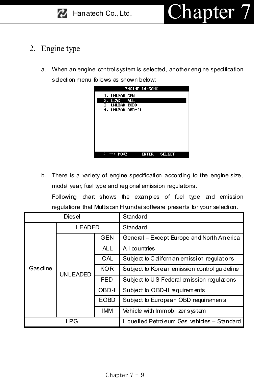
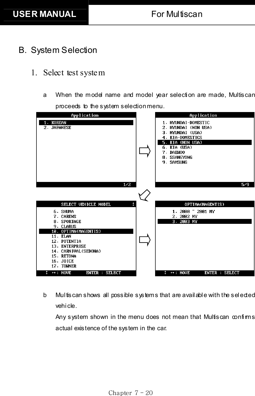
![USER MANUAL For Multiscan GjG^GTG ]G2. USA / NON-US A Exports a. As explained above, in export market, Hyundai and Kia maintained the same model name quite long, therefore, it is necessary to specify the model year and other details to successfully establish communication with the control module. b. A detailed model name and model year listings are provided for your s electi on, and followed by t he s ys tem s election.](https://usermanual.wiki/Hanatech/MULTISCAN/User-Guide-415188-Page-151.png)
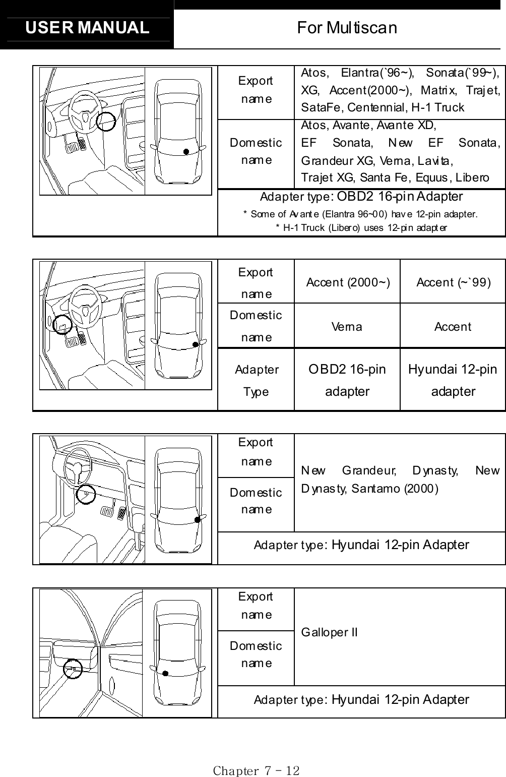
![Han atech Co., Ltd. Chapter 7 Gj G^G TGXXGGC. Diagnostic Adapter Location a. The DLC adapter location drawings are purely from t he experience of Hanatech and provided for your reference only. b. The drawings are based on Left Hand Drive cars, therefore, you may have to consider the mirror image for the Right Hand Drive cars. c. You can view these drawings on the Multiscan screen by selecting [3.Connector Location] after sel ecting [Hyundai (Dom es tic / Non-USA / USA)] from the car make list. 12-pin Mitsubishi / Hyundai adapter 16-pin OBD2 adapter Export name Excel, Scoupe, Sonata (~`98), Marcia, LPG Taxi, H-100 Truck, H -1, Santamo, Elantra(~`95), Grandeur Domestic name Excel, Scupe, Tiburon, Sonata I, II, III, Marcia, LPG Taxi, Porter, Starex, Santamo, Elatra, Grandeur Adapter type: Hyundai 12-pin Adapter](https://usermanual.wiki/Hanatech/MULTISCAN/User-Guide-415188-Page-156.png)
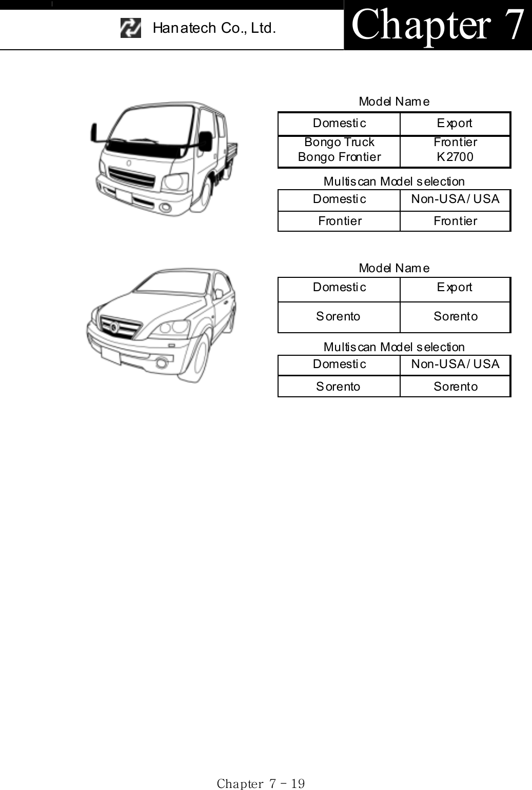
![USER MANUAL For Multiscan Gj G^G TGX]GModel Name Domestic Export Spectra Wing S h um a II Spectra Multiscan Model selection Domestic Non-USA / USA Spectra Shuma Model Name Domestic Export Carens Carens Multiscan Model selection Domestic Non-USA / USA Carens Carens Model Name Domestic Export Sportage Sportage Multiscan Model selection Domestic Non-USA / USA Sportage Sportage Model Name Domestic Export Credos Credos II Clarus Multiscan Model selection Domestic Non-USA / USA Credos / Credos II Clarus](https://usermanual.wiki/Hanatech/MULTISCAN/User-Guide-415188-Page-161.png)
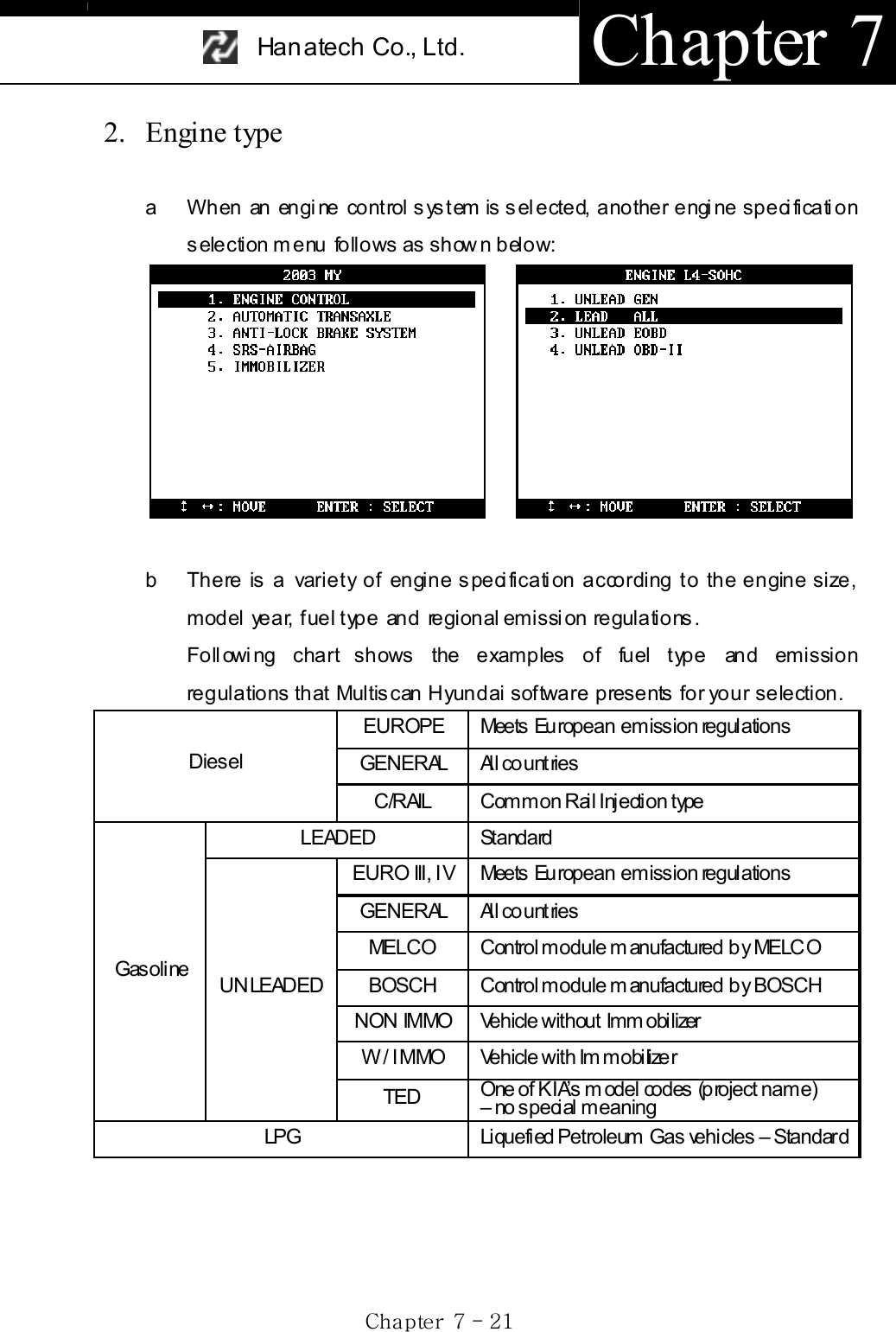
![USER MANUAL For Multiscan Gj G^G TGYYGC. Diagnostic Adapter Location a. The DLC adapter location drawings are purely from the experience of Hanatech and provided for your reference only. b. The drawings are based on Left Hand Drive cars, therefore, you may have to consider the mirror image for the Right Hand Drive cars. c. You can view these drawings on the Multiscan screen by selecting [3.Connector Location] after selecting [KIA (Dom estic / Non-USA / USA)] from the car make list. 14-pin circular adapter 20-pin adapter 16-pin OBD2 adapter Export name Joice Domestic name C ars tar Adapter type: Hyundai 12-pinExport name Optima (Magentis), Visto Domestic name Optima, Optima R egal , Visto Adapter type: OBD2 16-pin](https://usermanual.wiki/Hanatech/MULTISCAN/User-Guide-415188-Page-167.png)
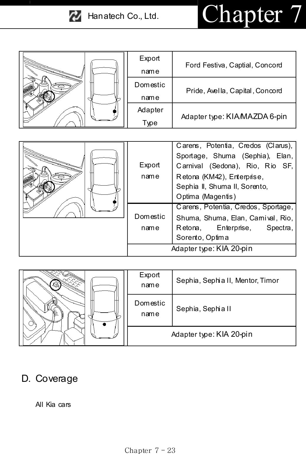
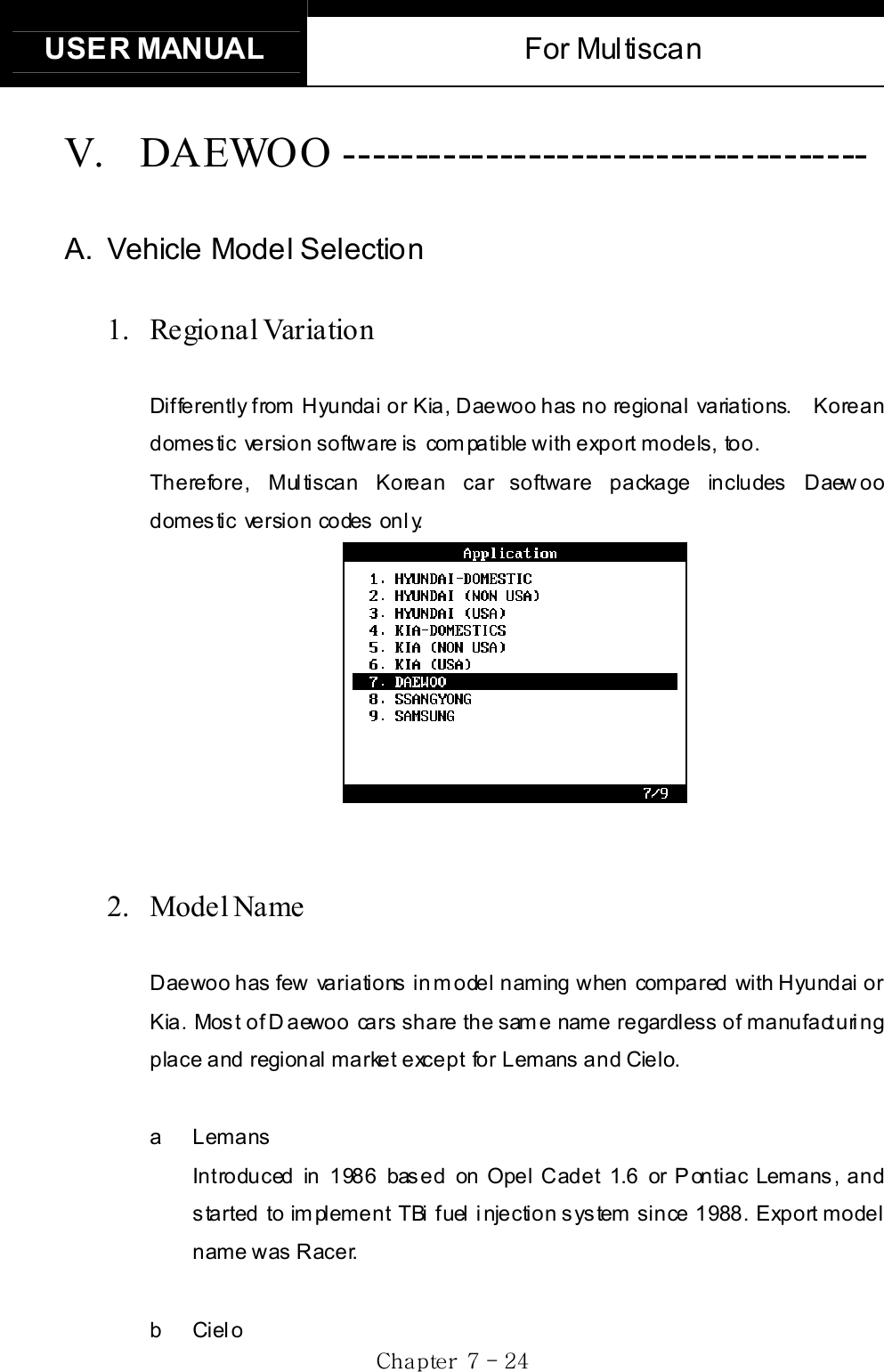
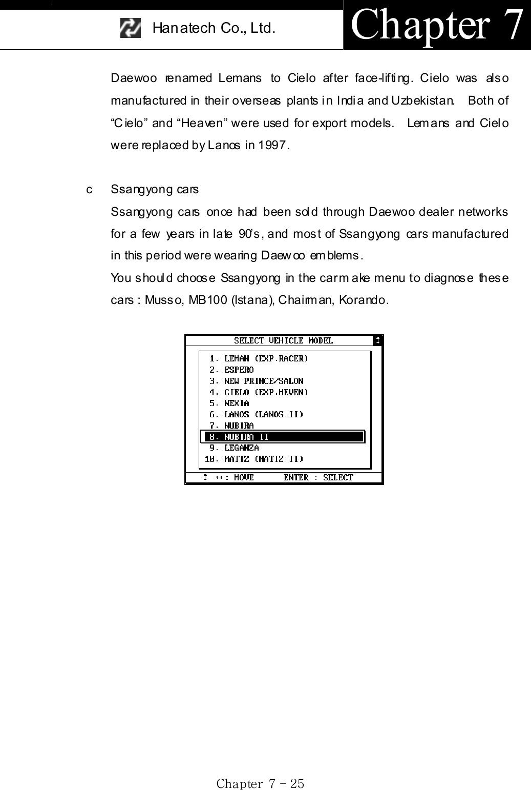
![USER MANUAL For Multiscan Gj G^G TGY]GB. System Selection G1. Menu Se lection A s ys tem selection menu promptly foll ows the model name s el ection. Mul tis can Daewoo s oftw are does not require you to make s electi ons am ong complicated model codes and applied emission regulations. A simple engine size and model year selection menu follows when [Engine control] system is selected. 2. Auto Transmission Until late 1990’s, “New Prince / Salon” of Daewoo had mechanical type automatic transmission, not the electronic control type. These mechanical types are not subject to scanner communication.](https://usermanual.wiki/Hanatech/MULTISCAN/User-Guide-415188-Page-171.png)
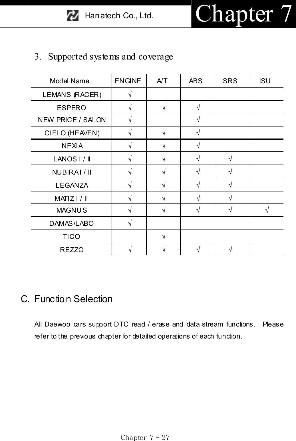
![USER MANUAL For Multiscan Gj G^G TGY_GD. Diagnostic Adapter Location a. The DLC adapter location drawings are purely from the experience of Hanatech and provided for your reference only. b. The drawings are based on Left Hand Drive cars, therefore, you may have to consider the mirror image for the Right Hand Drive cars. c. You can view these drawings on the Multiscan screen by selecting [3.Connector Location] after selecting [DAEWOO VEHICLES] from the car make list. 12-pin adapter 16-pin OBD2 adapter Model Name NUBIRA II Adapter type: OBD2 16-pin Model Name Magnus Leganza Adapter type OBD2 16-pin DAEWOO 12-pin](https://usermanual.wiki/Hanatech/MULTISCAN/User-Guide-415188-Page-173.png)
![Han atech Co., Ltd. Chapter 7 Gj G^G TGY`GModel N am e Damas, Labo Adapter type: DAEWOO 12-pin Model Name Matiz Adapter type: DAEWOO 12-pin Model Name Lemans(Racer), Espero, New Price / Salon, Cielo(Heaven), Nexi a, Ti co, Lanos , Nubira Adapter type: DAEWOO 12-pin E. Coverage All Daewoo cars Refer t o the [B-3. Supported System s and Coverage] f or furt her inform ation.](https://usermanual.wiki/Hanatech/MULTISCAN/User-Guide-415188-Page-174.png)
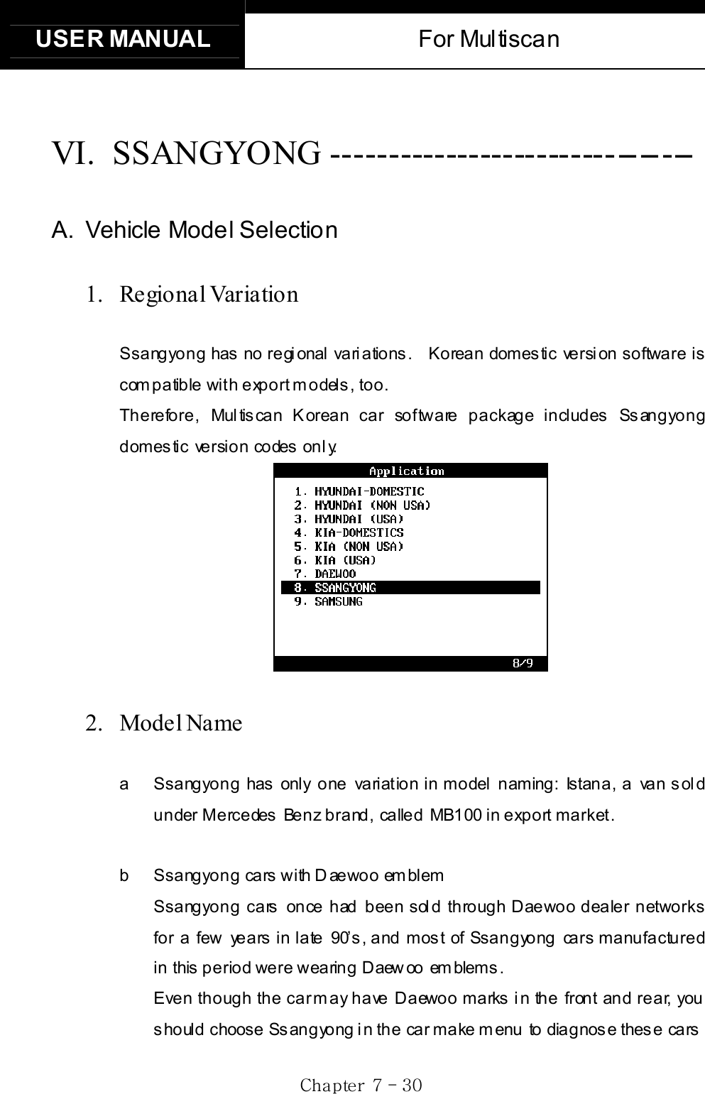
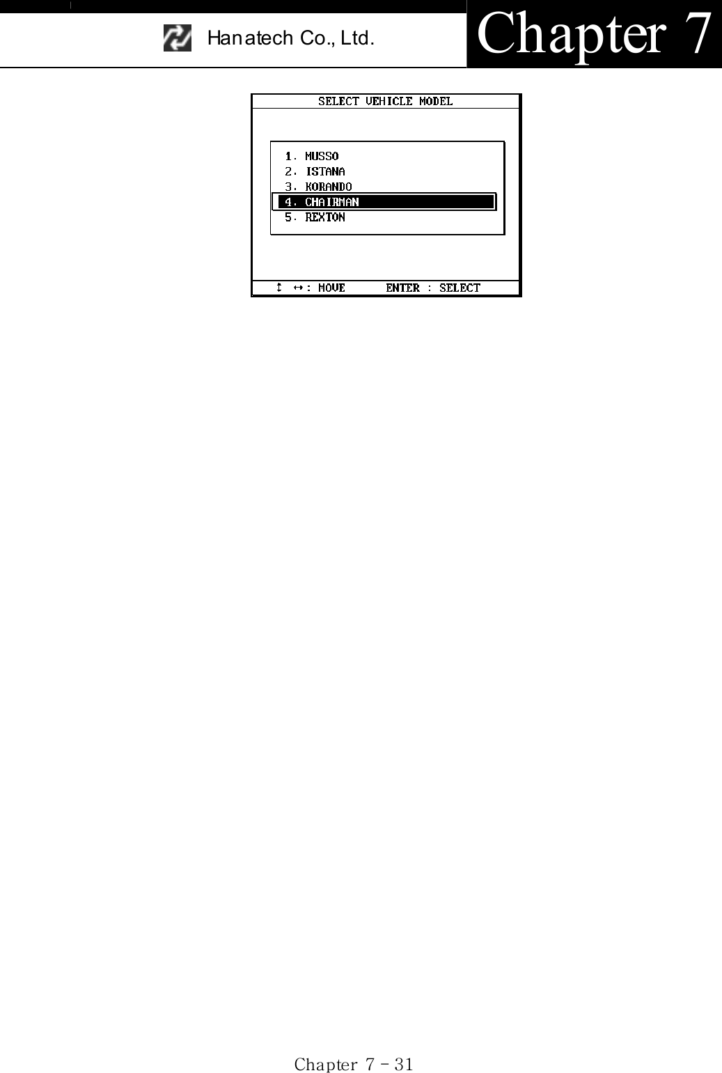
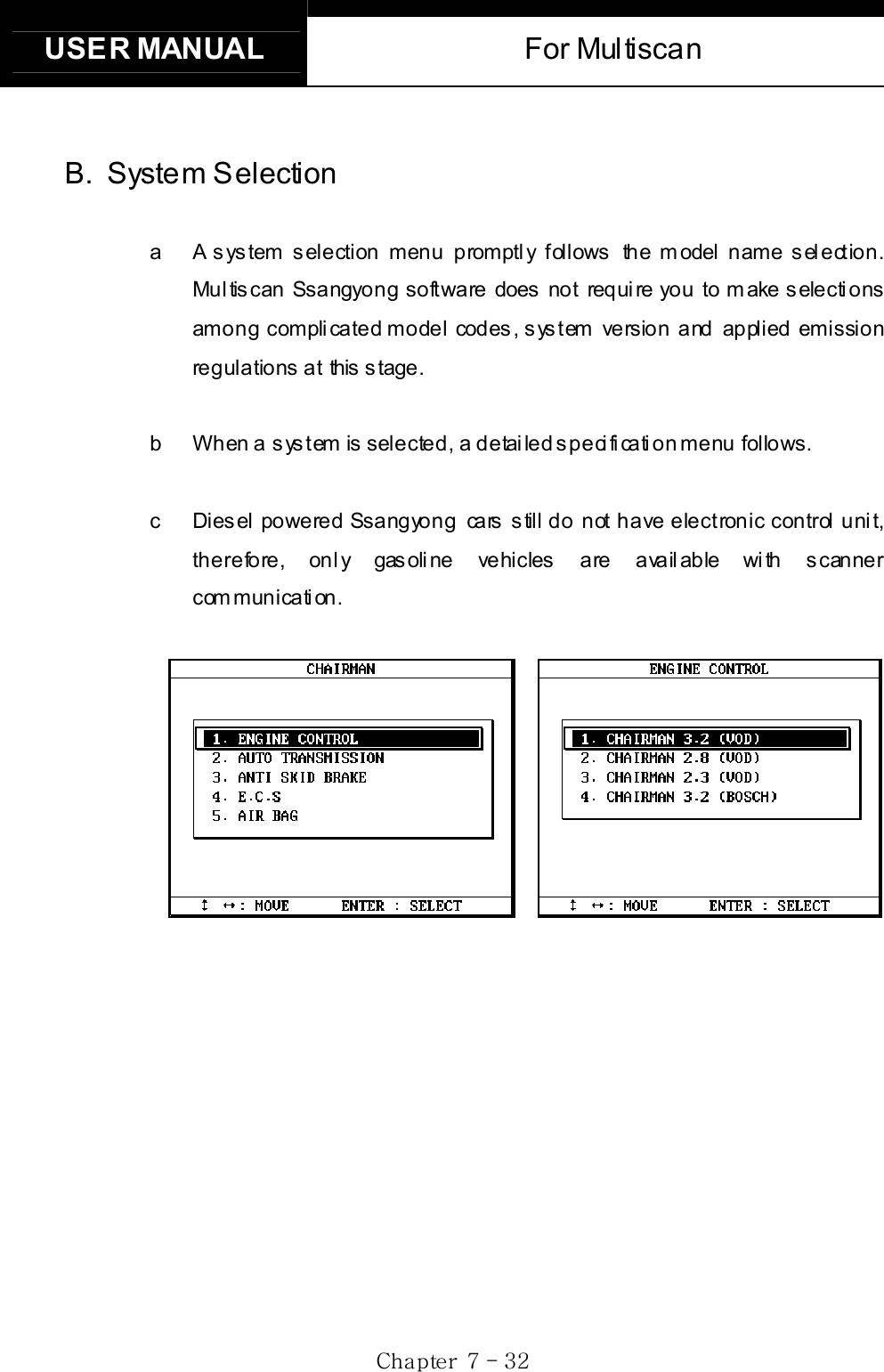
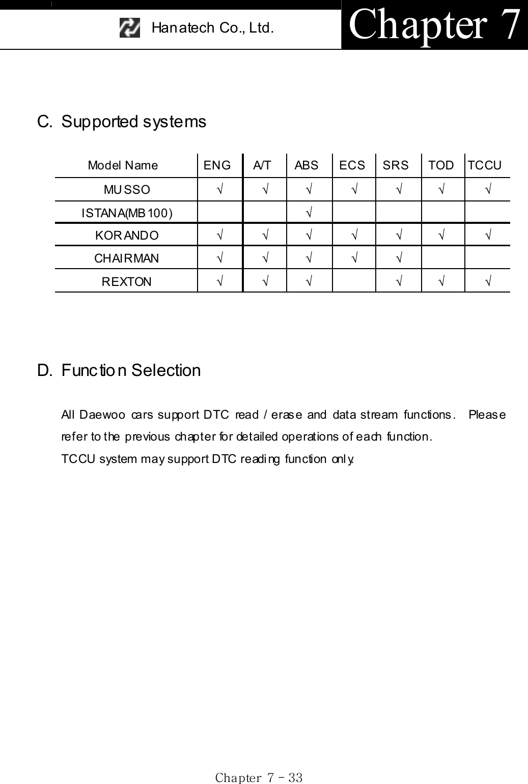
![USER MANUAL For Multiscan Gj G^G TGZ[GE. Diagnostic Adapter Location a The DLC adapter location drawi ngs are purely f rom the experience of Hanatech and provided for your reference only. b The drawings are based on Left Hand Drive cars, therefore, you may have to consider the mirror image for the Right Hand Drive cars. c You can view these drawings on the Multiscan screen by selecting [3.Connector Location] after selecting [DAEWOO VEHICLES] from the car m ake lis t . 14-pin circular adapter 20-pin adapter 16-pin OBD2 adapter Model Name Korando, Musso (before 1999) Adapter type: 14-pin circular or 20-pin](https://usermanual.wiki/Hanatech/MULTISCAN/User-Guide-415188-Page-179.png)
![Han atech Co., Ltd. Chapter 7 Gj G^G TGZ\GModel Name Chairman Adapter type: 14-pin circular You have to remove the plastic cover Model Name Istana (MB100) Adapter type: 14-pin circular This dra wing i s base d on passe nger car.You may have to access the adapter t hr ough the engin e compar tment f or t his kind of v an.Model Name Musso, Rexton Adapter type: 16-pin OBD2 F. Coverage Refer to the [C. Supported Systems] section hereinbefore.](https://usermanual.wiki/Hanatech/MULTISCAN/User-Guide-415188-Page-180.png)
![USER MANUAL For Multiscan Gj G^G TGZ]GVII. SAMSUNG ---------------------------------- A. Background Renault-Nissan-Samsung a Samsung motor company’s official name is Renault-Samsung motor company, and is a family of Renault-Nissan network, and manufactures knockdown models of Nissan cars in the assembly plant in Korea. Samsung has two models of SM5 and SM3, which are the same as Nissan Maxima and Bluebird. b The electronic control system of these Nissan cars are directly migrated to Samsung cars wi th leas t modifi cation, and therefore, the s canner communication is the same as ordinary Nissan cars. Refer to the Nissan section in the previous chapter for further information. c The licensed models are basically prohibited to sell in other countries, therefore, Samsung cars are found in a few limited countries. Samsung SM5 being sold in Chile is renamed to SQ5. B. Supported Systems Model Name ENGINE A/T ABS SRS IVMS SM5 (SQ 5 ) ¥¥¥¥ ¥SM3 ¥¥¥¥](https://usermanual.wiki/Hanatech/MULTISCAN/User-Guide-415188-Page-181.png)
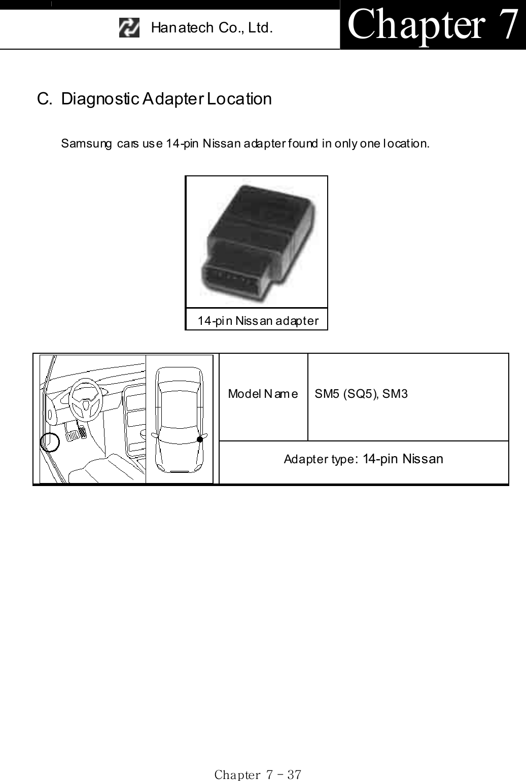
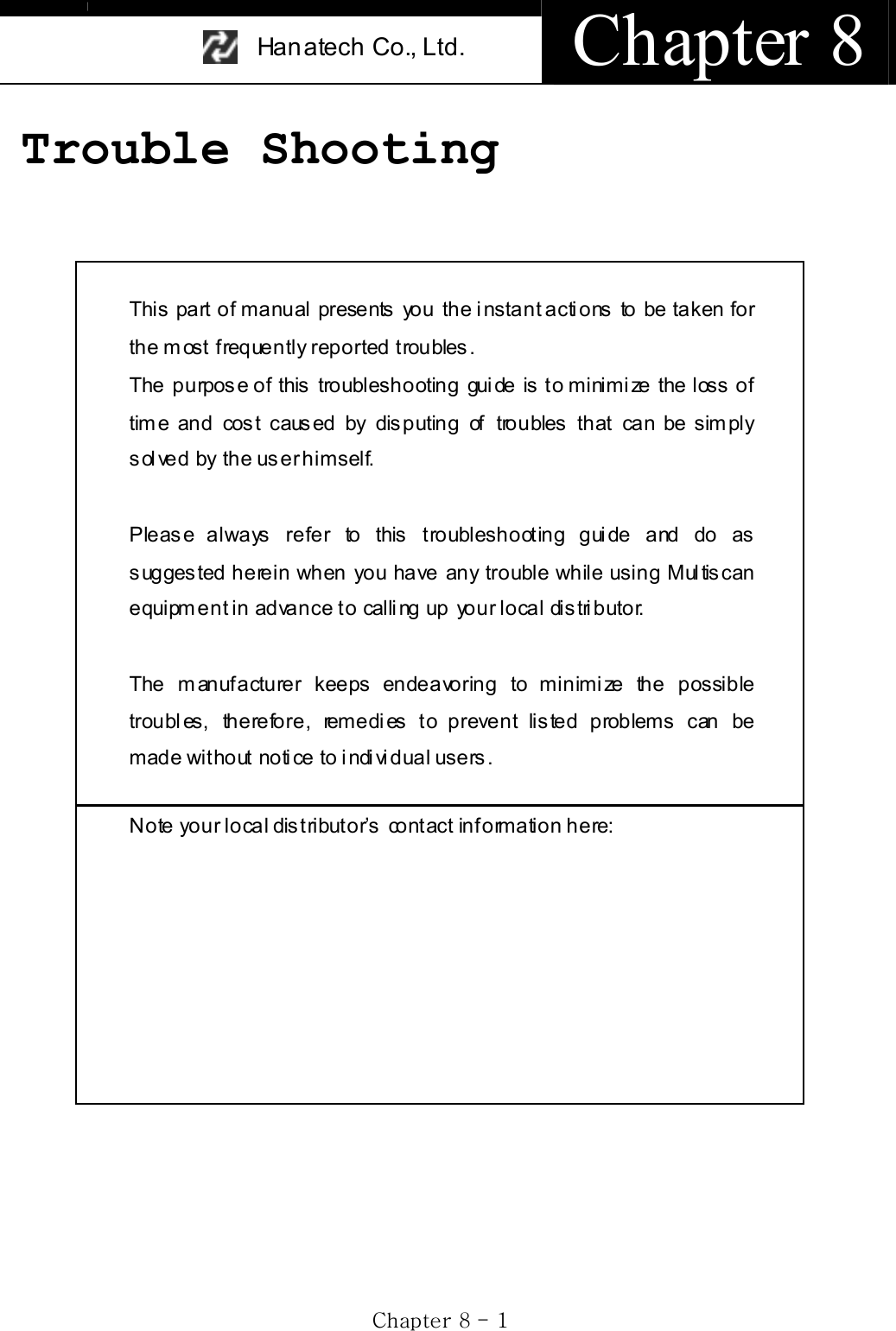
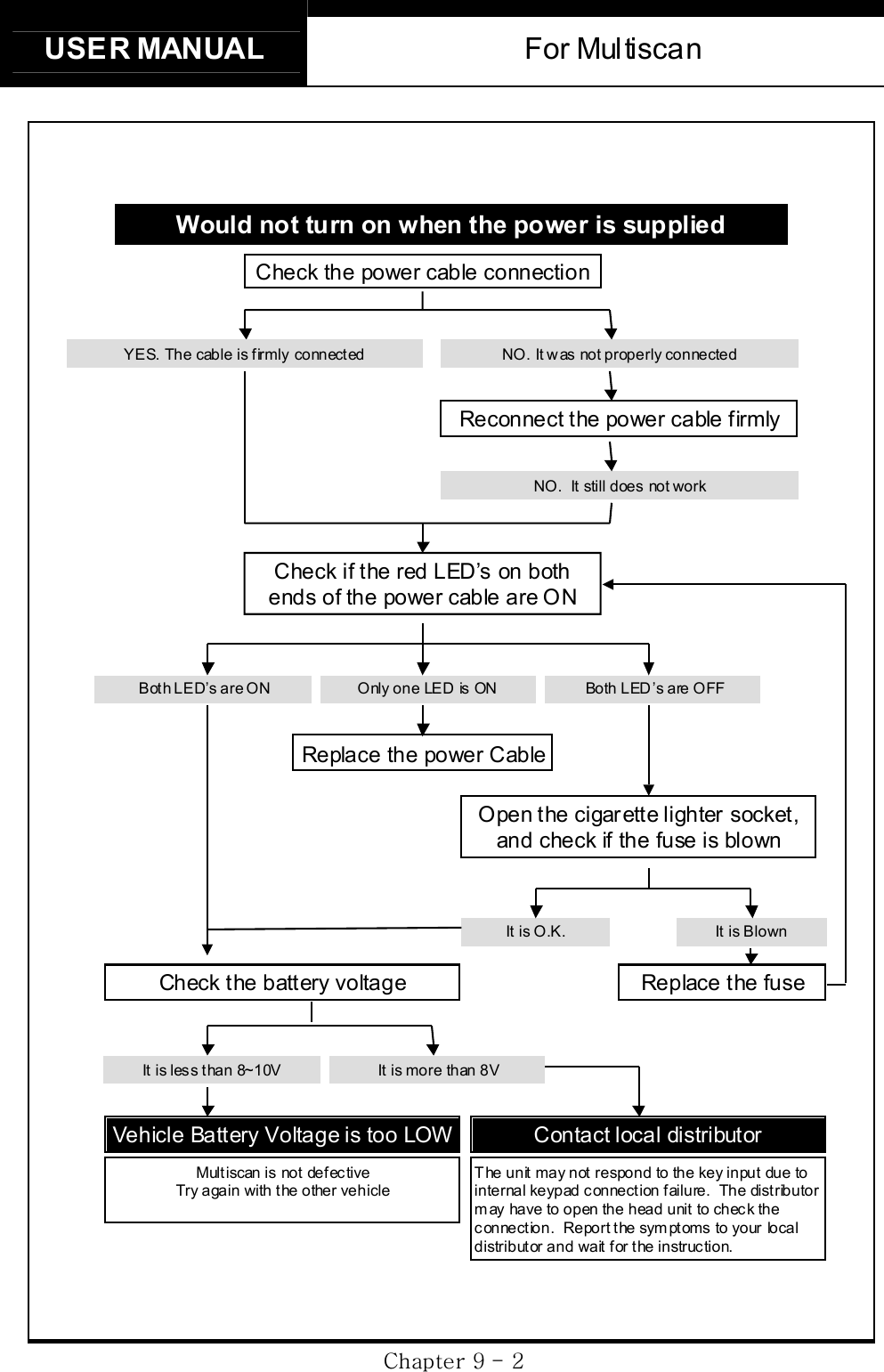
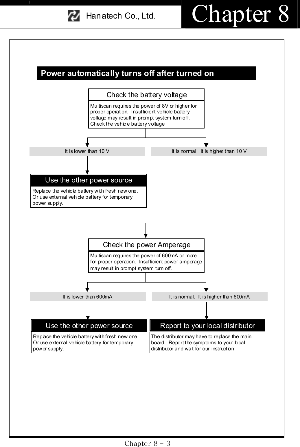
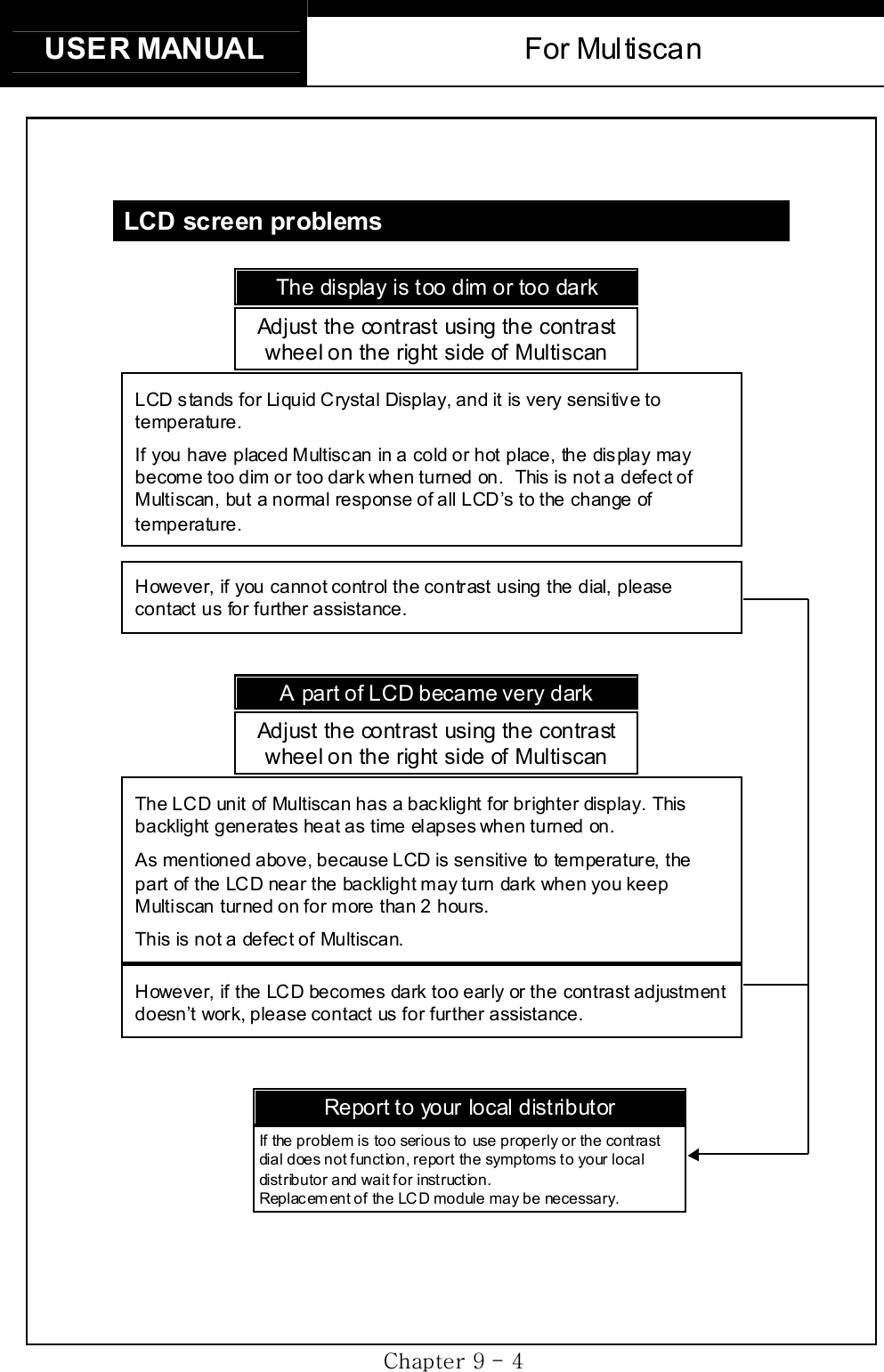
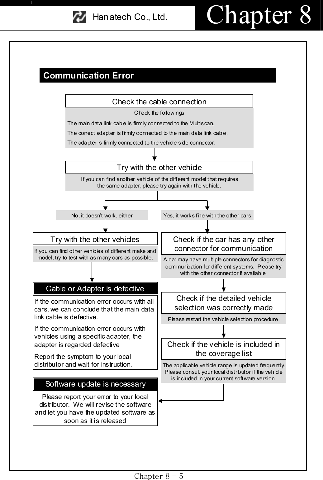
![USER MANUAL For Multiscan GjG`GTG ]GٻٻٻٻٻٻHanatech Co., Ltd. Autom otive Diagnostic Equipment Specialist ٻٻٻٻٻٻoTiVkSG_WTXSGzTSG GnTOnGPSGGnTOnPSGrUGwGjaG^ZW`XZGPhone: +82-54-454-9009 Fax: +82-54-454-8554 Website: http://www.hanatech.net Copyright 2003 by Hanat ech Co., Ltd. P ublished in KoreaGG](https://usermanual.wiki/Hanatech/MULTISCAN/User-Guide-415188-Page-189.png)