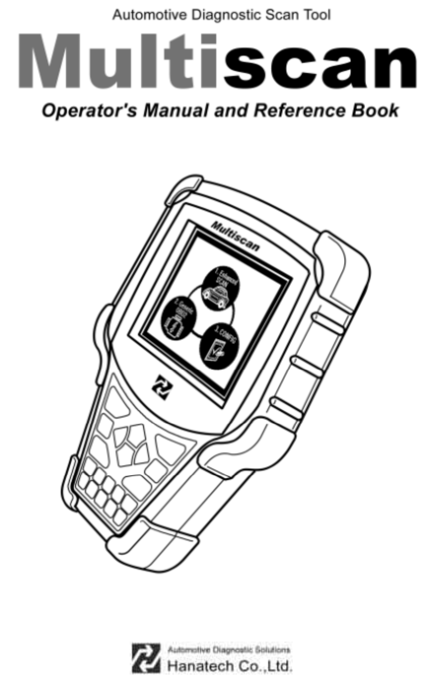
Hanatech MULTISCAN Automotive Handheld Scantool User Manual User s Manual H
Hanatech Co.,Ltd Automotive Handheld Scantool User s Manual H
Hanatech >
users manual

EUT Type: Automotive Handheld Scantool
FCC ID : RZXMULTISCAN
Test Report No.: GETEC-E3-04-014
FCC Class B Certification
APPENDIX G
: USER’S MANUAL
G

G
G
ٻ
ٻ
ٻ
ٻ
CHAPTER 1 SAFETY AND WARRANTY
I. SAFETY INSTRUCTIONS …………. 1 - 2
II. SAFETY PRECAUTIO NS …………. 1 - 4
III. WAR RANT Y SERVICE …………. 1 - 6
FCC RF INTERFERENCE STAT EMENT …………. 1 - 8
Han atech Co., Ltd. Chapter 1
G
jGXGTG XG
Safety and Warranty
G
About this Manual
All rights reserved by Hanatech Co., Ltd., Gumi, Korea.
The contents of this manual are the result of contributions by dozens
of individuals all who have added their vital expertise and experience to
the evolution of the contents of this manual.
The information contained in this manual may contain printing errors
and is subject to change without notice according to product upgrade.
Hanatech shall not be liable for errors contained herein or for incidental
or consequential damage in connection with the furnishing, performance,
or use of this material.
N o part of this m anual may be photocopied, reproduced, or translated
to another language in any way without the prior written consent of
Hanatech Co., Ltd.ٻ
ٻ
ٻٻٻ
ٻ
Using this Manual
It is recommended that the user become familiar with the
operating procedures , term inologies and informati on contained
within this user’s manual. This will help to increase the user’s
effectiveness with this equipment.
Vehicle system familiarity
While this equipment provides very powerful functions with extensive
vehicle coverage, it cannot replace knowledge and skill. To get the
most out of this equipment, a full understanding of vehicle systems is
required. It is recommended that the equipment be used in conjunction
with the original service manual for the vehicle being tested.
The equipment is designed for use by trained service personnel and
this manual assumes that the service technician who is going to use this
equipment has a familiarity with vehicle electronic control systems,
however, the lates t servi ce manuals and bulletins s hould always be
referenced before using this equipment.ٻ
USER MANUAL For Multiscan
G
jGXGTG YG
I. SAFETY INSTRUCITONS -----------------------
Thank you for purchasing Multiscan. To get the maximum performance of the
equipment, please carefully read this manual first, and keep it at hand.
On delivery inspection
When the equipment is delivered, a check should be made for any damaged or
missing components. If the unit is damaged or fails to operate according to the
specifications, contact your local distributor or the manufacturer, Hanatech Co., Ltd.,
Hana bldg., 80-1 Songjung-dong, Gumi-shi, Kyung-buk Republic of Korea 730-090.
In the unli kel y event the equipm ent requires shipping back to the manufacturer, pleas e
use the original packing material.
Safety symbols
The following symbols are used throughout this manual:
DANGER
This mark means that dangerous consequences may
arise, with the possibility of death or serious injury to the
user, if the machine is handled incorrectly.
WARNING
This mark means dangerous consequences may arise,
with the possibility of somewhat serious injury to the user
and or damage to the machine and facilities, if the
equipment is handheld incorrectl y.
SYMBOL Description
This symbol is affixed to locations on the equipment where
the operat or s houl d cons ult correspondi ng topics in this
manual (which are also marked with the symbol) before
using relevant functions of the equipment. In the manual,
this symbol indicates explanations that are particularly
important that the user is expected to read the manual before
using the equi pment.
This sym bol represents DC (Direct Current)
Han atech Co., Ltd. Chapter 1
G
jGXGTG ZG
Safety guideline
In order to ensure proper operation and satisfactory performance, observe the
cauti ons lis ted bel ow.
DANGER
This equipment is designed to comply with IEC61010-1 safety standards, and
has been tested for safety prior to shipment. Excessive high voltage measurement
or improper operation could result in personal injury, as well as damage to the
equipment or the vehicle. Please read this manual carefully and be sure that you
understand its contents before using the equipment.
The manufacturer disclaims all responsibility for any accident except for that
resulting due to defect in its product.
WARNING
For safety reasons, this equipment should not be used to
measure circuits carrying more than 30Vrms or 42.4V peak.
To avoid el ectri cal accident that could res ult i n i njury or
death, do not measure voltage in excess of these limitations.
Maximum rated measurable voltage is 30Vrms or 42.4V
peak.
USER MANUAL For Multiscan
G
jGXGTG [G
G
II. SAFETY PRECAUTIONS -----------------------
G
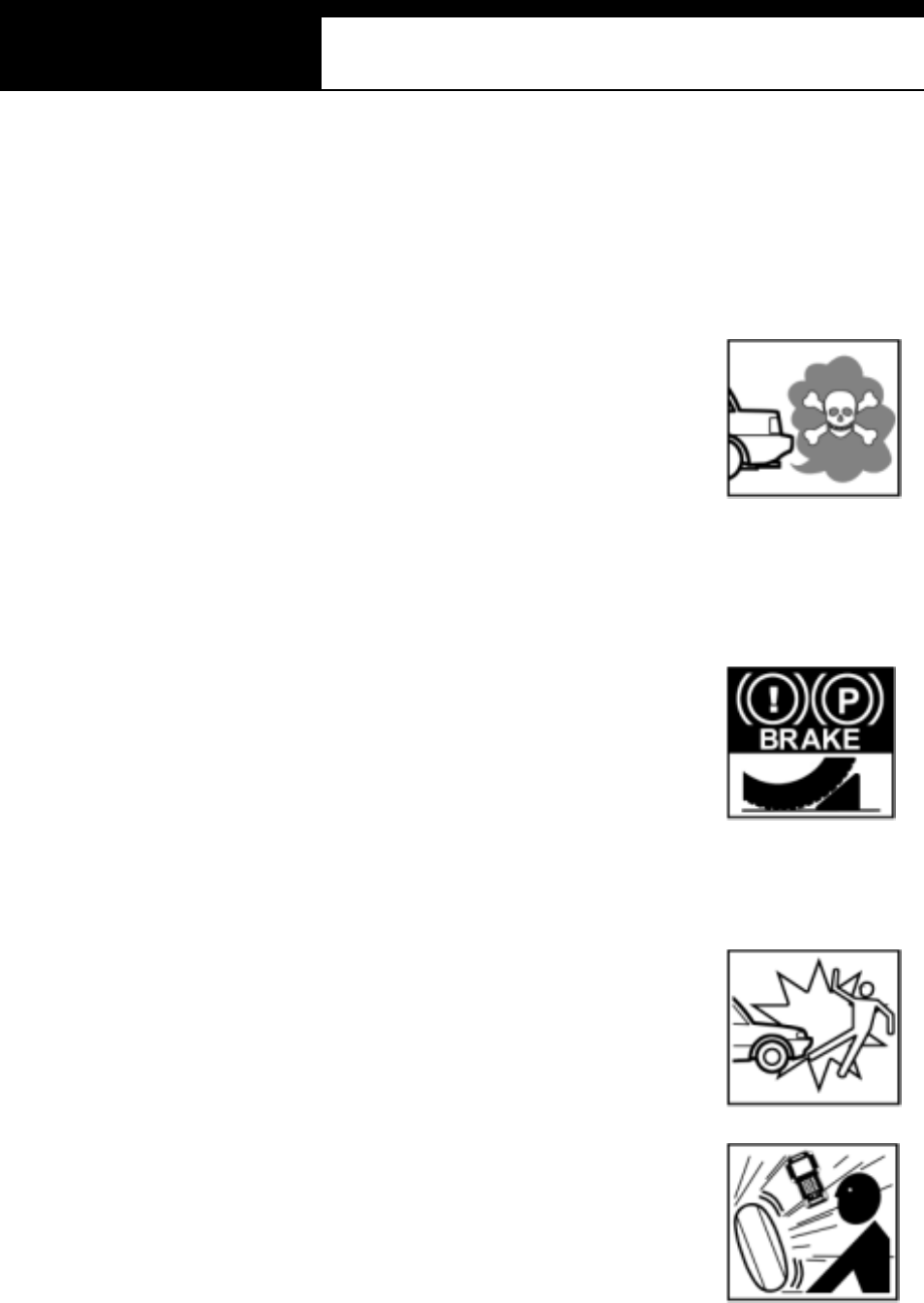
DANGER
When an engine is running, keep the workshop area WELL
VENTILATED or attach a building exhaust removal system to the
engine exhaust system. Engines produce carbon monoxide, an
odorless and poisonous gas that causes slower reaction time
and may lead to serious injury or death.
G
G
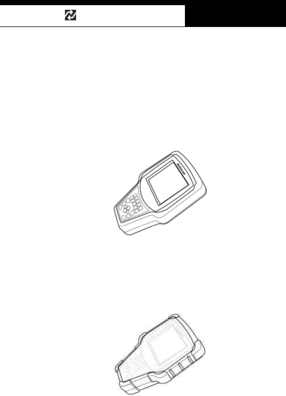
WARNING
Brakes and wheel blocks
Apply the hand brake and block the wheels before using the test
equipment. It is highly recommended to block the wheels on
front-wheel drive vehicles because the hand brake does not hold
the driving wheels.
G
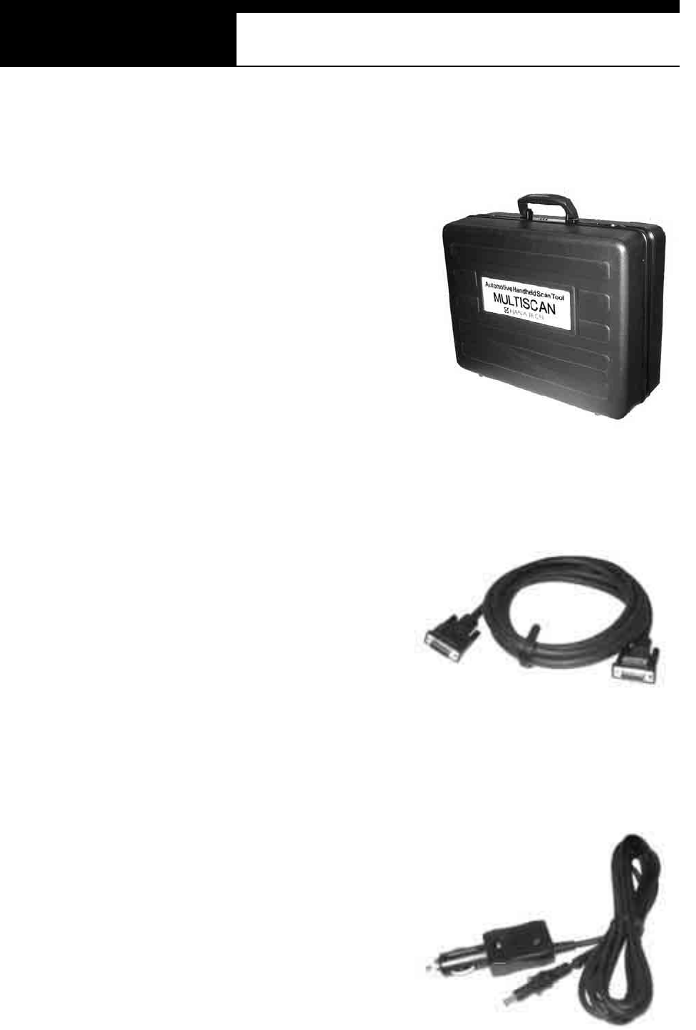
Drive Test
Do not drive the vehicle and operate the test equipment at the
same time. Any distraction may cause an accident. Have one
person operate the test equipment while the other person drives
the vehicle.
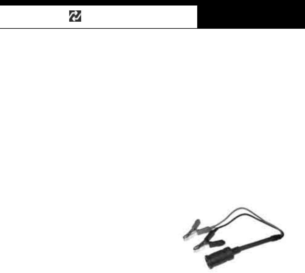
Never place the test equipment in front of you when driving the
vehicle becaus e the test equipm ent may hi t your body and caus e
s erious inj ury when the ai r bag infl ates .
D o not try to tes t the SRS air bag s ystem while dri vi ng the
vehicle as unintended air bag inflation may result.

Han atech Co., Ltd. Chapter 1
G
jGXGTG \G
Engine Compartment
Maintain sufficient clearance between moving components or
belts while using the test equipment in the engine compartment.
Moving components and belts may catch loose clothing, test
cables or a part of your body and cause damage or personal
injury.
Electrical Components
Always turn the ignition key OFF when connecting or disconnecting electrical
components unless otherwise instructed.
Vehicle Battery
Multiscan is designed to prevent damage from reverse polarity battery cable
connection, however, it is always highly recommended to always ensure correct
polarity terminal connection.
Never lay the test equipment on vehicle battery. You may short the terminals and m ay
cause damage to your body, the test equipment or the battery.
To avoi d dam agi ng t he tes t equi pm ent or dis playing fals e data, make s ure the vehicl e
battery is f ully charged and the connections to the el ect ronic control m odul e are clean
and tight.
The warning messages above and the safety messages contained hereinafter cover
situations Hanatech is aware of. Hanatech cannot know, evaluate or advise you as to
all of the possible hazards. You must make sure that any conditions or service
procedures encountered do not jeopardize your personal safety.
G
G
G
G
G
G

USER MANUAL For Multiscan
G
jGXGTG ]G
G
III. WARRANTY SERVICE -------------------------
Warranty Period
In principle, Multiscan is warranted to the consumer to be free of defects in material
and workmanship for the period of 3 years after the date of purchase.
If the product is found defective during this period, the product can be returned to
Hanatech and will be repaired or replaced free of charge.
Freight and repair Cost
For the repair of head unit, Hanatech covers the freight cost for the service during one
year from the date of purchase, and you can send the troubled unit to your local
distributor without having to pay the freight cost. You should consult with your local
distributor about the validity of remaining warranty period before sending the unit.
For the remaining two years, you are liable for any international cost incurred. Repair
or replacement will be provided free of charge.
When the warranty period is expired after three years, the customer must pay the
round trip freight and the repair or replacement cost.
Upon delivery
Hanatech inspects all the ordered product parts and components are included in the
package before shipment, and includes the original copy of pre-shipment inspection
report in the box. As soon as the product is delivered to you, please ensure
everything you ordered is properly checked and included referring to the pre-shipment
inspection report. If there is anything missing or damaged, you must notify the local
distributor immediately within 3 working days from the delivery date for free of charge
replacement of the parts.
In case of trouble
If you encounter any malfunction or trouble with the equipment, please refer to the
Trouble Shooting chapter in this manual. If the problem cannot be solved, please
contact your local distributor for assistance. For early identification of a fault or error,

Han atech Co., Ltd. Chapter 1
G
jGXGTG ^G
your local distributor will require the following details:
1. Symptom of problem you are experiencing
2. Serial num ber of the head unit
3. Vehicle information: Which specific car were you testing when the problem
occurred – Model name, Model year and system ID number if available (for Mitsubishi,
Subaru and Suzuki only: Refer to Japanes e car chapter for details )
Warranty Void
Even in the effective warranty period, if the problem is found to be caused by any of
the followings, Hanatech charges the cost for round trip freight and actual cost for the
service to the customer, and the shipment back to the customer will be suspended
until the customer’s payment is duly made
1. Evidence of improper use or application of the product ignoring the cautions and
warnings stipulated in the user’s manual
2. Intentional damage or modifications to the product or user’s attempt to repair
without proper authorization
3. Any damage caused by Force Majeure including war and natural disaster
4. Loss of time, inconvenience and other consequential damage or loss
Warranty void seal
In addition to the above m entioned warranty void conditions, warranty service is not
provided in case the warranty void seal is broken or removed.
If you remove the head unit safety boot, you will see a yellow round sticker covering
one of the screw holes in the back. Please be careful not to break this seal and never
try to open the head unit without direct authorization from the manufacturer.
Bought in other countries
Only the products properly supplied by the contracted authorized local distributors are
recognizable for free of charge warranty service. Any equipment bought outside the
contracted national territory of your local distributor will be charged for service.

USER MANUAL For Multiscan
G
jGXGTG _G
Note
This equipment has been tested and found to comply with the limits for a Class B
digital device, pursuant to Part 15 of the FCC Rules.
These limits are designed to provide reasonable protection against harm ful
interference in a residential installation.
The equipment generates, uses and can radiate radio frequency energy and, if not
install ed and used i n accordance with the ins t ructi ons , may caus e harmful i nt erference
to radio communications. However, there is no guarantee that interference will not
occur in a particular installation.
If this equipment does not cause harmful interference to radio or television reception
which can be determined by turning the equipment off and on, the user is encouraged
to try to correct the interference by one or more of the following measures:
-Reorient or relocate the receiving antenna
-Increase the separation between the equipment and receiverG
-Connect the equipment into an outlet on a circuit different from that to which the
receiver is connectedG
CAUTION
Changes or modification not expressly approved by the party responsible for
compliance could void the user’s authority to operate the equipment.
G
G
THIS DEVICE COMPLIES WITH PART 15 OF THE FCC RULES. OPERATION I
S
SUBJECT TO THE FOLLOWIN G TWO CONDITIONS: (1) THIS D EVICE MAY NO
T
CAUSE HARMFUL INTERFERENCE. AND (2) THIS DEVICE MUST ACCEPT AN
Y
INTERFERENCE RECEIVED INCLUDING INTERFERENCE THAT MAY CAUSE
UNDESIRED OPERATION.G
FCC RF INTERFERENCE STATEMET

G
G
ٻ
ٻ
ٻ
ٻ
CHAPTER 2 SPECIFICATION AND PARTS
I. SPECIFICATION …………. 2 – 1
II. PART LIST …………. 2 – 3
A. Head unit and basic supplies 2 - 3
B. Diagnostic Adapters 2 - 6
C. Spare Parts 2 - 13
D. O ptional Supplies 2 - 13

Han atech Co., Ltd. Chapter 2
G
jGYGTG XG
Specification and Parts
I. Specification -----------------------------------
A. Hardware
CPU: 16bit, 33MHz
RAM: 1 Mbyt e (SR AM)
Program Cartridge Memory: 128Mbytes built-in Flash Memory
Display: 320Ý240 Monochrome Graphic LCD with Back Light
Key Pad: 20 membrane keys, embossing type
Com Port: USB and RS232
Printer: General PC printer
Power: DC 8~18V, 600m A or higher
B. Envi ronmental Specificatio n
Indoor use only
Operating temperature: Max 50ଇ / 122
Maxim um relative hum idit y: 80% (up to 31ଇ/88) and 50% (40ଇ/104 or
higher)
Installation overvoltage categories: CATซ
Maximum measurable voltage: DC 30V Max
Pollution degree 2
Max. Alti tude: Up to 2000m

USER MANUAL For Multiscan
G
jGYGTG YG
G
C. Mechanical Di mensions
Length: 222ໄ / 9 "
Width: 187ໄ / 7.5"
Height: 51ໄ / 2 "
Wei ght: 950g / 2.1 lb (head uni t onl y)
Body Color: Dark Grey
Safety Boot Col or: Yel low / Blue / RedG
All specifications are subject to change without notice for the purpose of product
and quality improvem ent.
Han atech Co., Ltd. Chapter 2
G
jGYGTG ZG
II. Part List -----------------------------------------
A. Head unit and basic supplies
1. Head Unit
(P/N. )
- Made of strong ABS resin, each unit has passed internal impact test
before shipment. .
2. Safety Boot
(P/N. )
- Flexible plastic cover that protects the head unit from physical,
chem ical and elect rical dam age
-Basic color is blue, however, it can be changed according to the
distributor’s demand.
G
USER MANUAL For Multiscan
G
jGYGTG [G
3. Carry Case (P/N. )
Provides convenient transportation
and the protection of the head unit
and other components f rom outer
physical impact during the
transportation and storage. Carry
case is provided when purchasing
the head unit and at least one
software package together.
Includes keys and dial l ock
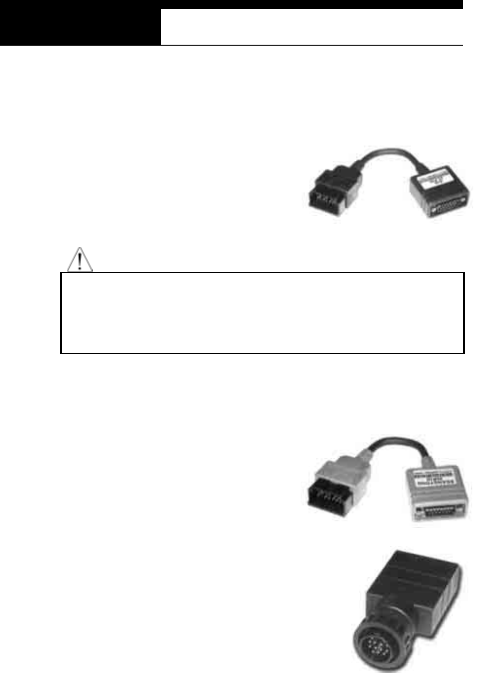
4. Ma in Data Link Cable
(P/ N .
3001-0001)
ڈٻ Connects vehicle side DLC and Multiscan head unit for data transmission.
ڈٻ Connecting parts on both ends
are exactly same, therefore,
simply put any one end to the
head unit, and then hook the
other end to the vehicle s ide
DLC after connecting an
appropriate adaptor
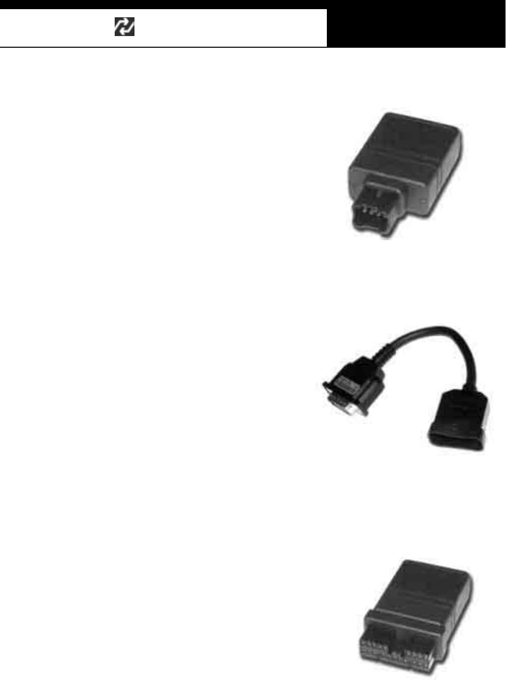
5. Power Cable 1 – C igarette Lighter (P/N. 3000-0004)
ڈٻ Supplies power to the head uni t
from the cigarette li ghter socket.
Used when DLC is located near
the driver or passenger seat and
pow er is not supplied through
DLC.
Han atech Co., Ltd. Chapter 2
G
jGYGTG \G
ڈٻ LED lights on both ends turn ON when power is properly supplied.
ڈٻ The metal plunger part in the end of cigarette lighter connector is
removable by unscrewing for the fuse replacement. It may become
loose over repeated use, therefore, it is highly recommended to check if
it is tightly screwed frequently. A set of plunger parts are included in the
basic supplies. Refer to spare parts section hereinafter.
ڈٻ The rated voltage and current for this power cable are 12V and less than
2A.
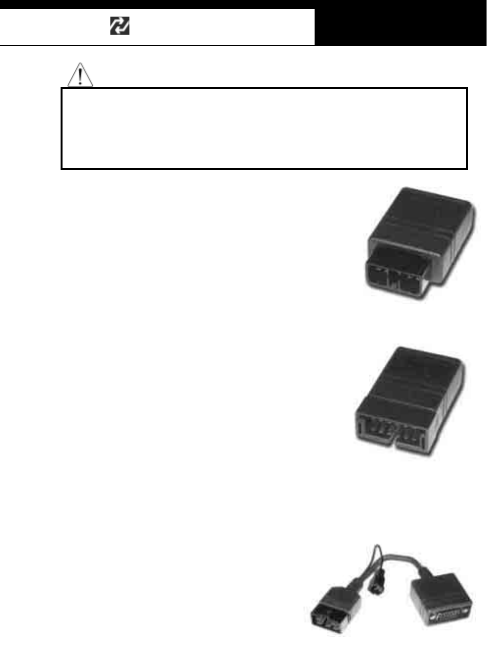
6. Power cab le 2 – Vehicle Battery (P/N. 3000-0005)
- Supplies power from the vehicle battery when the DLC is located in
the engine bay or when using the oscilloscope or multi-meter
functions
-Connect each of the two
alli gator clips to the battery
term inal of the correct
pol ari ty wi th caution.
-Must be used together with
the Power Cable 1. Insert
the cigarette lighter adaptor of the Power Cable 1 into the socket,
and connect the other end to the head unit.
- Red LED light turns ON when power is properly supplied from the
vehicle battery.ٻ
USER MANUAL For Multiscan
G
jGYGTG ]G
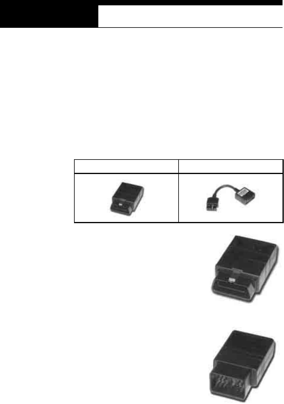
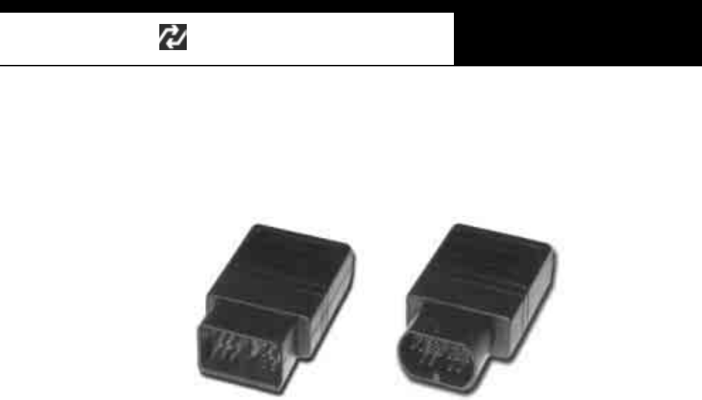
B. Diagnostic Adapters
Diagnostic adapters are sold separately, therefore check if all the adapters
you ordered are included in the package upon delivery.
There are two types of adapters: capsulated and wired types.
Mos t of Mul tis can DLC adapters are capsul ated for bett er durability and
s torage, however, s om etimes i t is diffi cult or alm ost im possible to connect t he
capsulated adapter to vehicle side DLC when it is located deep inside
beneath t he das hboard. W e use wi re type adapters for t he cars s uch as
Hyundai and Kia that we were reported to have such connecting difficulties.
Capsule type Wire type
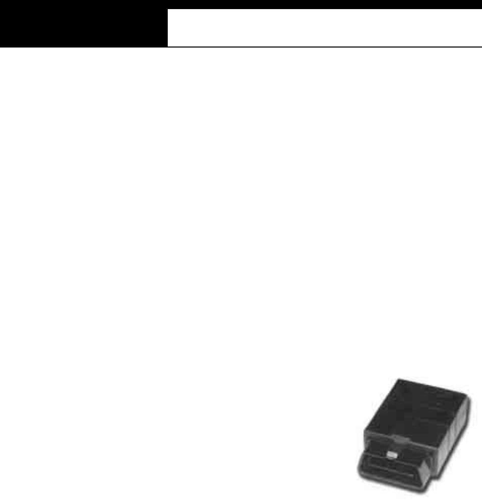
1. OBD2 Sta ndard Adapter
(P/N. 3001-0010)
Used for all OBD generation 2 and EOBD
com pa tible ve hicl es . Vehi cle side D LC is
generally located near the driver’s seat and
most frequently found beneath the dash panel.
2. Toyota / Lexus 17Pin Rectangular
Adapter (P/ N. 3001-0011)
Us ed for t he diagnosis of Toyota and Lexus
of OBD generation 1. Vehicle s ide D LC of
this type is generally located in the engine
com pa rtm en t .
Han atech Co., Ltd. Chapter 2
G
jGYGTG ^G
3. Toyota/Lexus 17Pin Semi-circular Adapter (P/N. 3001-0012)
Also used f or the diagnos is of Toyota and
Lexus of OBD generation 1.
The vehi cl e si de DLC is general ly found
beneath the dashboard.
Refer to the following warning message.
WARNING
The appearances of this adapter and MAZDA 17Pin adapter are exactly
same, however, the internal wiring and circuit are different. Check the
engraved name and the body color of the adapter carefully before use.
Im proper adapter connection may result in serious malfunction of
either control system and Multiscan head unit.
4. Honda 3 P in Adapter and 2 Pin Jump Wire
(P/N. 3-pin: 3001-0014, 2-pin wire: 3001-0023)
3-pin adapter is used for the diagnosis of Honda
cars of OBD generation 1 that support DTC
read and erase as well as data stream.
Older Honda cars have 2-pin DLC that supports
DTC read only. The jump wire is used for these
older cars to bridge the 2-pin DLC terminals.
The vehicle side DLC is generally located under
the dashboard or the glove box.
USER MANUAL For Multiscan
G
jGYGTG _G
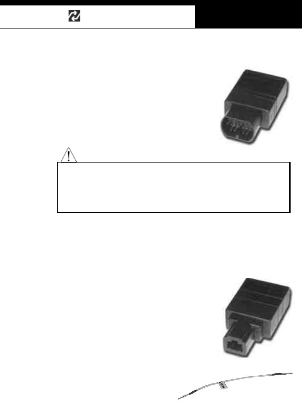
5. Mitsubishi and Hyundai 12Pin Adapter (P/N. 3001-0001)
Us ed for t he comm uni cation
with Mitsubishi and Hyundai
cars of OBD generation 1.
A wire type adapter is provided
as the connecting difficulties of
caps ule type adapter in quite a
few H yundai cars were
reported.
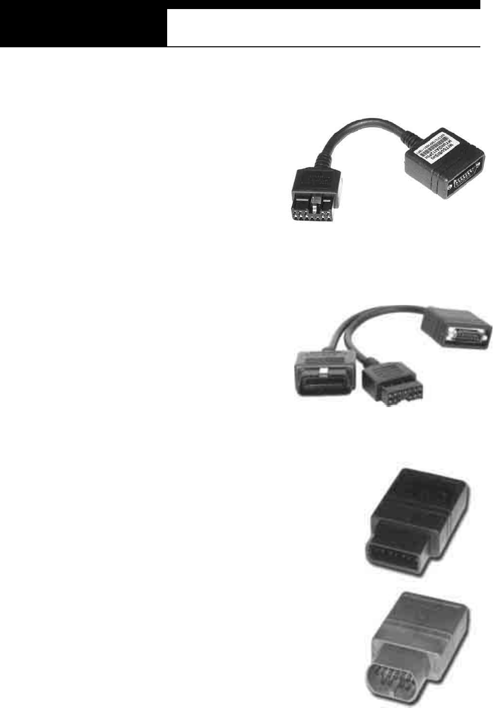
6. Mitsubishi 12+16pin dual headed adapte r (P/N: 3001-0030)
Us ed for the com munication with
Mitsubishi cars with both of 12-pin
OBD1 and 16-pin OBD2 adapters
on-board.
R e fe r to th e Mi ts u bis hi s e c ti on ,
Chapter 6 for details.
7. Nissan and Samsung 14Pin Adapter (P/N. 3001-0006)
Used for the communication with Nissan cars
of OBD generation 1 and all Samsung
passenger cars.
Vehicle side DLC is generally found under the
dash or inside the fuse box.
8. Ma zda 17Pin Adapte r (P / N . 30 01 - 0 01 3 )
Us ed fo r th e c om m uni cat io n w i th Ma zd a c a rs
of OBD generation 1.
Vehicle side DLC is generally located in the
engine com partm ent.
Refer to the warning message i n the next page:
Han atech Co., Ltd. Chapter 2
G
jGYGTG `G
WARNING
The appearances of this adapter and Toyota 17Pin SEMI-CIRCULAR adapter
are exactly same, however, the internal wiring and circuit are different. Check
the engraved name and the body color of t he adapter carefull y before use.
Improper adapter connection may result in serious malfunction of either
control system and Multiscan head unit
9. Subaru 9P in Adapter (P/N. 3001-00)
Used for the communication with Subaru cars of
OBD generation 1.
The vehicle side DLC is generally located
beneath the dashboard.
10. GM Daewoo 12P in Adapter
(P/N. 3001-00)
Us ed fo r the c om m un i ca ti on wi t h D ae wo o ca rs
of OBD generation 1.
The vehicle side DLC is generally located
beneath the glove box, door side.
11. Kia 6Pin Adapter (P /N. 3001-0003)
Us ed for the communicati on with old
Kia cars of OBD generation 1.
Onl y the Diagnos ti c Troubl e C ode
reading function is available for the
cars with this type of adapter as only
the slow pulse signal is transmitted
through the vehicle side DLC.
The split wire of the adapter is to be connected to the ground terminal of
the vehicle side DLC.
USER MANUAL For Multiscan
G
j GYG TGXWG
12. Kia 20Pin Adapter (P/N. 3001-0004)
Us ed for the communication with Kia cars of OB D generati on 1.
DTC read & erase and data stream
functions are available for the cars
with this type of adapter.
Refer to the following warning
message.
WARNING
The appearances of Kia 20Pin adapter and Ssangyong 20Pin Rectangular
adapter are exactly same, however, the internal wiring and circuit are different.
C heck the engraved name and the body color of the adapter carefully before
use. Improper adapter connection may result in serious m alfunction of
either control system and Multiscan head unit
13. Ssangyong 20Pin Rec tangular Adap ter (P/N. 3001-0005)
Used for Ssangyong cars of OBD
generation 1.
Vehicle side DLC is located in the
engine compartment.
Refer to the warning above.
14. Ssangyong 14Pin Circular Adapter
(P/N. 3001-0007)
Used for old Ssangyong cars of OBD
generation 1.
Vehicle side DLC is located in the engine
compartment.
Han atech Co., Ltd. Chapter 2
G
j GYG TGXXG
15. Holden 6 Pin Adapter(P/N. 3001-0023)
Used for Australian Holden of OBD
generation 1.
Japanese cars such as Toyota and Nissan
assem bl ed i n Aus tralia wi th Holden buil t
engines may have this type of adapter, too.
Vehicle side DLC is generally located
beneath the glove box to the center facia.
16. GM Opel 10Pin Adapter (P/N. 3001-0019)
Used for the com munication with
Opel cars of OBD generation 1.
Also available with Multiscan
Australian Holden, South American
Opel and European Vauxhall
s oftw are packages .
Vehicle side DLC is generally
located in the fuse box beneath the dashboard or near the parking brake.
17. Ford 20 Pin Adapter(P/N. 3001-0020)
Used for the communication with Ford cars
of OBD generation 1, including Australian
and British Fords.
Vehicle side DLC is generally located in the
fuse box beneath the dashboard.
USER MANUAL For Multiscan
G
j GYG TGXYG
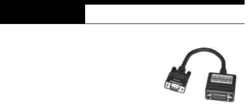
18. Upgrade cab le
(P/ N . 30 0 0 -00 10 )
To be connected to main data link
cable for updating your Multiscan
software by downloading updated
codes from your PC. Refer to the
related chapter in this manual.
Han atech Co., Ltd. Chapter 2
G
j GYG TGXZG
C. Spare Parts
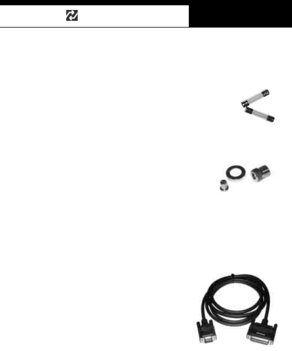
-Extra fuses (P/N. 3008-0003)
For the replacement of the fus e located inside the
ci garette li ghter power cable. You can als o replace
it with a fuse of which rated current is 2 Am pere or
less.
-Spare cigarette lighter power cable plunger parts
A set of spare parts for replacement when
the original parts are lost.
D. Op tional Supplies
1. Printer Cable
(P/N. 3000-0009)
To be connected between head unit
RS232 port and printer to enable direct
interface with a PC printer.
Compatible with the printers that support
PCL mode, and Hewlett Packard ® is
highly recommended.

G
G
ٻ
ٻ
ٻ
ٻ
CHAPTER 3 OPERATING Multiscan
I. GETTING STARTED …………. 3 – 1
A. Head unit 3 – 1
B. Main DLC Cable 3 – 2
C. Power Supply 3 – 3
D. Contrast 3 – 5
II. CONT ROL KEYS …………. 3 – 6
A. Key pad 3 – 6
B. Making Selection in the menu 3 – 6
C. Function keys 3 – 7
III. CONFIGURATION …………. 3 – 9
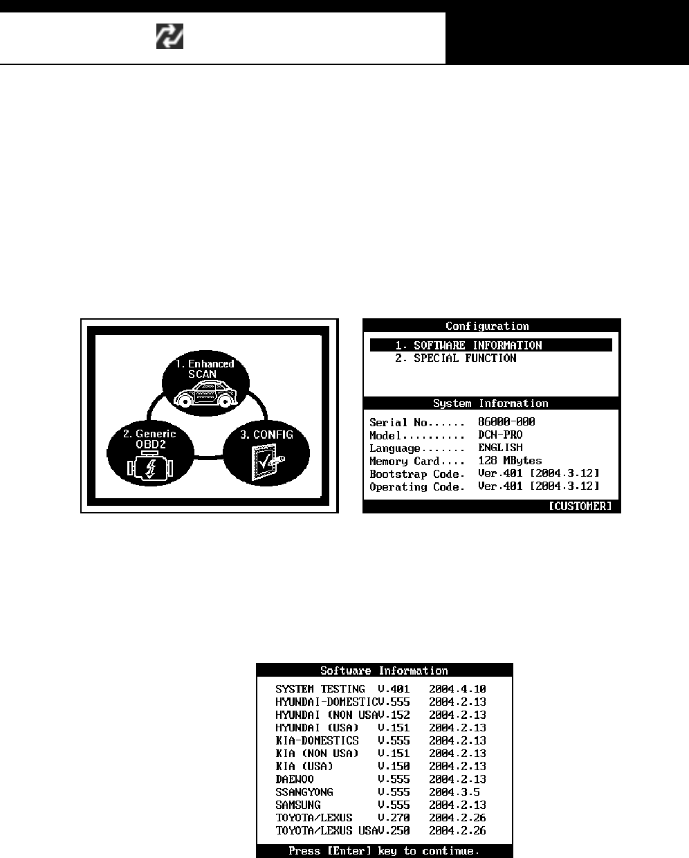
A. Software Information 3 – 9
B. Special Functions 3 – 10
Han atech Co., Ltd. Chapter 3
G
jGZGTG XG
Operating Multiscan
I. Getting Started---------------------------------
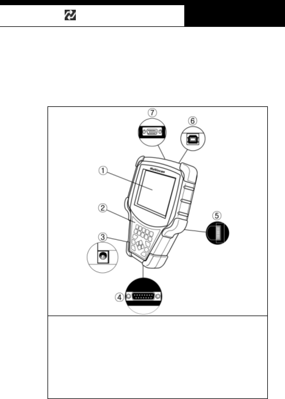
A. Head Unit
ཛ.GLCD Display
ཛྷ.GKey Pad (may be designed differently)
ཝ.G12V Power Jack Connection
ཞ.G15-pin Main DLC Cable Connection
ཟ.GLCD Contrast Adjustment Dial
འ.GUSB Communication port
ཡ.GRS232C Serial Communication Port
USER MANUAL For Multiscan
G
jGZGTG YG
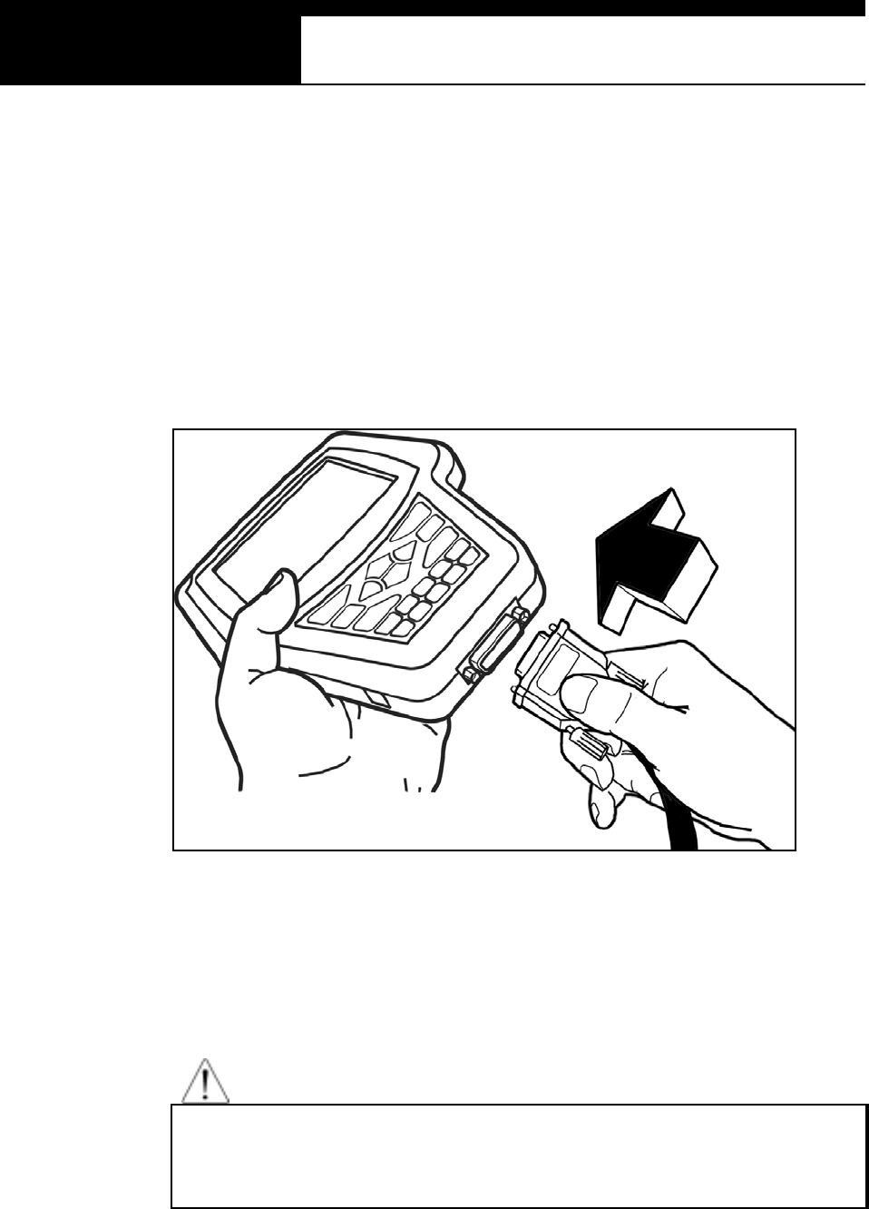
B. Main DLC Cable
1. Connection to the head unit
a. The male connectors in both ends of the main DLC cable are exactly
s am e and you can connect any of them to the head uni t.
b. Press the main DLC cable connector into the head unit 15 pin female
connector, and tighten up the two screws for firm connection.
2. Connecting the DLC adapters
Locate the vehicle side adapter and connect the corresponding DLC adapter
to the remaining male connector of the main DLC cable
CAUT ION
It is recom mended to keep the main DLC cable connected and s crewed
to the head unit. Frequent connection and removal of the main DLC
cable may loose the fastening parts and bend the connecting pins.
Han atech Co., Ltd. Chapter 3
G
jGZGTG ZG
C. Power supply
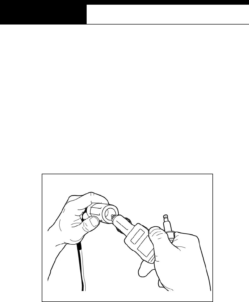
1. Power supplied through DLC adap ter
12V battery power is supplied through most of the DLC adapters except
GM/Daewoo 10Pin and Mitsubishi/Hyundai 12Pin adapters
2. Ciga re tte lighter
a. Use the cigarette lighter cable when power is not supplied through the
DLC adapter.
b. Insert the cigarette lighter connector into the socket, and check if the red
LEDs in both ends of the cable are ON.
c. Insert the power jack into the head unit power socket.
USER MANUAL For Multiscan
G
jGZGTG [G
3. Vehicle battery
a. Sometimes it is necessary to put the head unit in the engine
compartment when testing OBD1 generation vehicles with the
diagnostic adapters located near the engine, such as Toyota, Mazda,
Kia, Ssangyong, BMW, Mercedes Benz, etc.
b. In case power is not supplied through the diagnostic adapter,
connect the alligator clips of the battery power cable to the battery
terminals of correct polarity. Check the red LED on the round
socket turns ON.
c. Connect the cigarette lighter power cable connector into the battery
power cable socket.
4. Power ON
Multiscan automatically turns on when power is supplied properly..

Han atech Co., Ltd. Chapter 3
G
jGZGTG \G
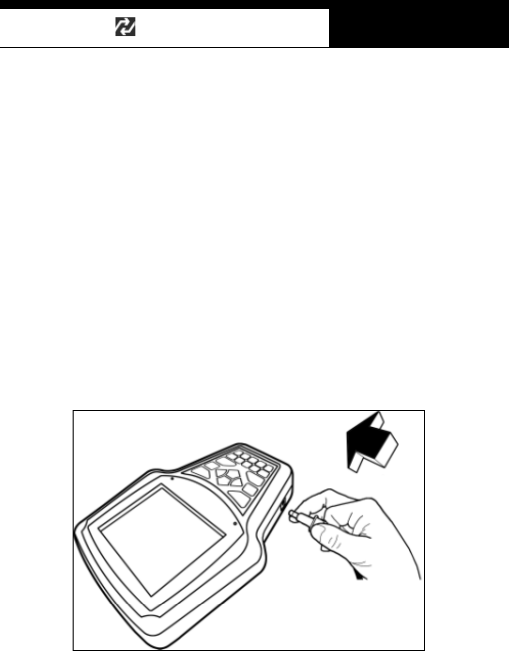
D. Contrast
a. The LCD display is sensitive to the temperature.
It may become too faint when it is cold and too dark when it is hot.
b. If the screen is too faint or too dark to read, you can adjust the contrast by
turning the contrast dial in the right side of the head unit.
c. In case of any trouble with the display, please refer to the Trouble Shooting
chapter i n this manual .
USER MANUAL For Multiscan
G
jGZGTG ]G
II. Control Keys -----------------------------------
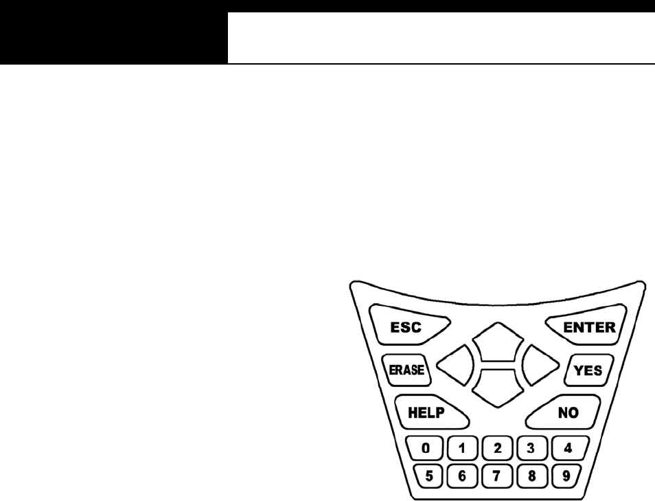
A. Keypad
The keypad is made of chemistry
proofing PVC material that
prevents contamination and
damage from hazardous oily
workshop environment.
The membrane keypad is designed
and tested to maintain its normal
operation over a million keystroke
for each.
Each key is rais ed for better tactile feel. The keypad has total of 20 keys .
B. Making selec tio n i n the me nu
1. Numeric Keypad in the bottom
Sim pl y press the corres pondi ng num ber when m aki ng s el ection from a menu.
This is available only when you are selecting an item of which number is 9 or
less. For more than 10, you should locate the highlighted bar on the desired
item and press the [ENTER] key.
2. Arrow keys in the middle

Han atech Co., Ltd. Chapter 3
G
jGZGTG ^G
ൖ ൘ Page Up/Down
Scroll Up/ Down
a. Scroll up and down the highlighted bar in the menu by pressing Up/Down
arrow keys and press the [ENTER] key to confirm the selection.
b. If the menu has more than 12 items, you may have to move between the
pages t o make selection. You do not have to pound on Up/Down arrow
keys to s croll the whole page. Sim pl y press ing the Left or Right arrow
key will shift page to page. Move the highlighted bar by pressing the
up/down keys when the desired item appears on the screen, and press
t h e [ EN T ER ] ke y.
c. If differently defined, key instructions will be given in the bottom of the
s creen.
C. Func tio n keys
1. ESC
Used to abort an operation of Multiscan or to return to the upper level menu.
If differently defined, key instructions will be given in the bottom of the screen.
2. HELP
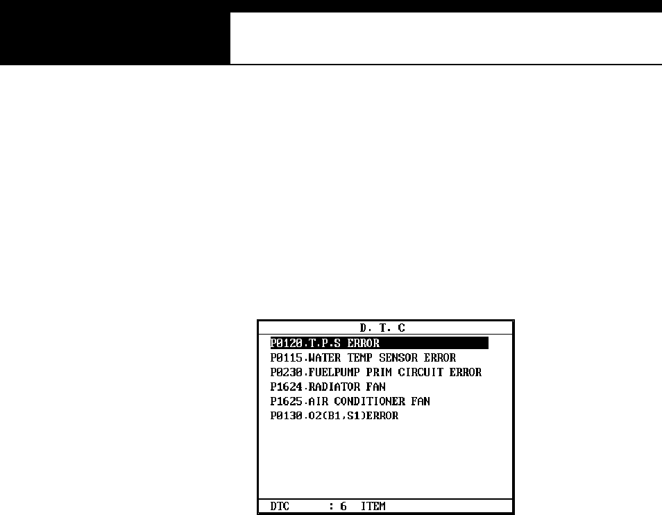
a. DTC Read
-When a trouble code is detected, you can press this key to view the
detailed information of the DTC.
-DTC definition, DTC registration conditions and check points are
provided (For Korean and Malaysian cars only as of May, 2003)

USER MANUAL For Multiscan
G
jGZGTG _G
b. Service Data (Live Data Stream)
-While live data is being displayed on the screen, select a live data
item by m oving the highlighted bar, and press this key to view the
detailed information about the selected item.
-Standard value and technical explanations are provided. (For
Korean and Malaysian cars only as of March, 2004)
3. ERASE
When one or m ore D TC (s ) are found, you can press t his butt on to erase the
DTC. A query to confirm your intention to erase the DTC will follow.
4. ENTER
a. To confirm the selection after locating the highlight bar on a desired item
in the menu.
b. To proceed to the next step when the instruction or pop-up message
appears.
c. To freeze the live data parameter in the top of the screen. Refer to the
freeze data function in the foll ow ing chapter.
d. If differently defined, key instructions will be given in the bottom of the
s creen.
Han atech Co., Ltd. Chapter 3
G
jGZGTG `G
III. Configuration ----------------------------------
Press the [3] key from the initial function menu to proceed to the configuration
menu. You can check the version numbers of the software packages contained
in the built-in 128MB memory, test the keypad and LCD, set up sound and
language options and download software updates in the configuration menu.
A. Software Information
When you select [1. SOFTWARE INFORMATION] in the configuration menu, a
list of software packages contained in the built-in memory will appear as below:
Should you get any update files from your local distributor or from Hanatech
website, please compare the version number and last update date to check if the
update is necessary.
USER MANUAL For Multiscan
G
jGZGTGXWG
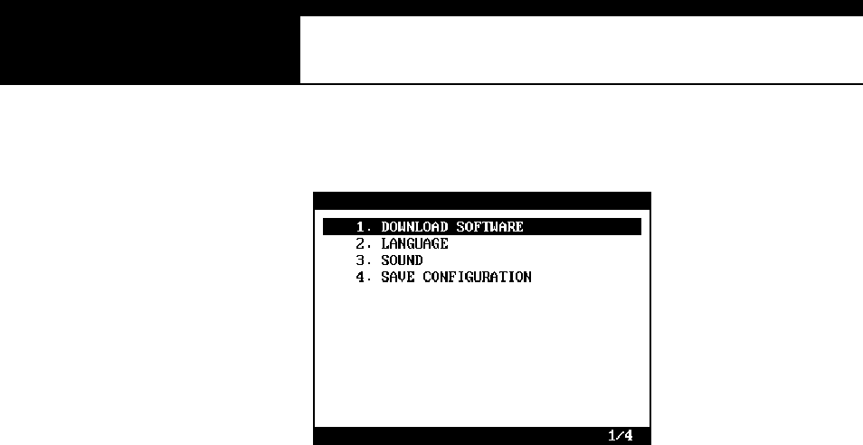
B. Special functions
G
1. Download software
-You can download the software updates from your PC when you
s elect [1. D OWNLOAD SOFTWARE].
-Instructions will be given separately whenever an update is available.
Contact your local distributor for the availability of update frequently
and keep posted of such events.
2. Language
-You can select provided language. English and Spanish languages
are available for selection as of March 2004.
3. Sound
-You can toggle ON and OFF the key sound.
4. Save Configuration
-If you have made any change in this [Special Function] menu, you
have to save the confi gurati on to m ake such changes ef fective.
-Press the [4] key to save the changes in configuration

G
G
ٻ
ٻ
ٻ
ٻ
CHAPTER 4 FUNCTIONS
I. DIAGNOSTIC T ROUBLE CODE …………. 4 – 1
A. DTC Read 4 – 1
B. DTC Erase 4 – 4
C. DTC Help Tips 4 – 5
II. CURRENT DATA …………. 4 – 6
A. Pulse Signal Type 4 – 6
B. Serial Communication Type 4 – 6
C. Data Freeze 4 – 7
D. Data Graph 4 – 8
E. Help Tips 4 – 10
III. ACTUAT ION TEST …………. 4 – 11
IV. BLACK BOX …………. 4 – 14
V. CONNECTOR LOCATION …………. 4 – 27
G
Han atech Co., Ltd. Chapter 4
G
jG[GTG XG
Multiscan Functions
The functions you can choose when all the test vehicle details are selected
properly are explained in this chapter of the manual. The actual list of
available functions may be different according to the vehicle you want to test.
I. Diagnostic Trouble Code---------------------
A. DTC Read
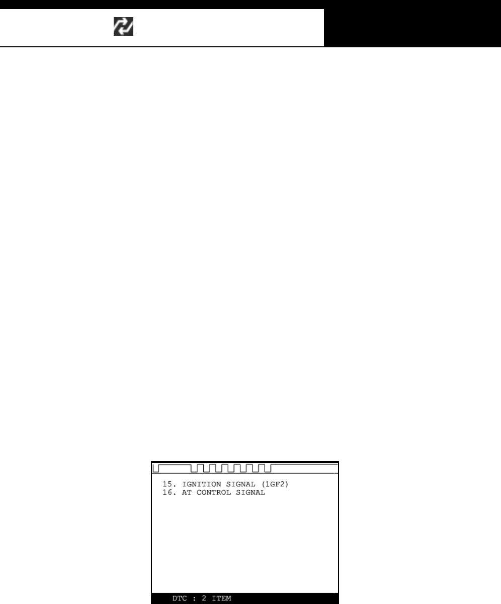
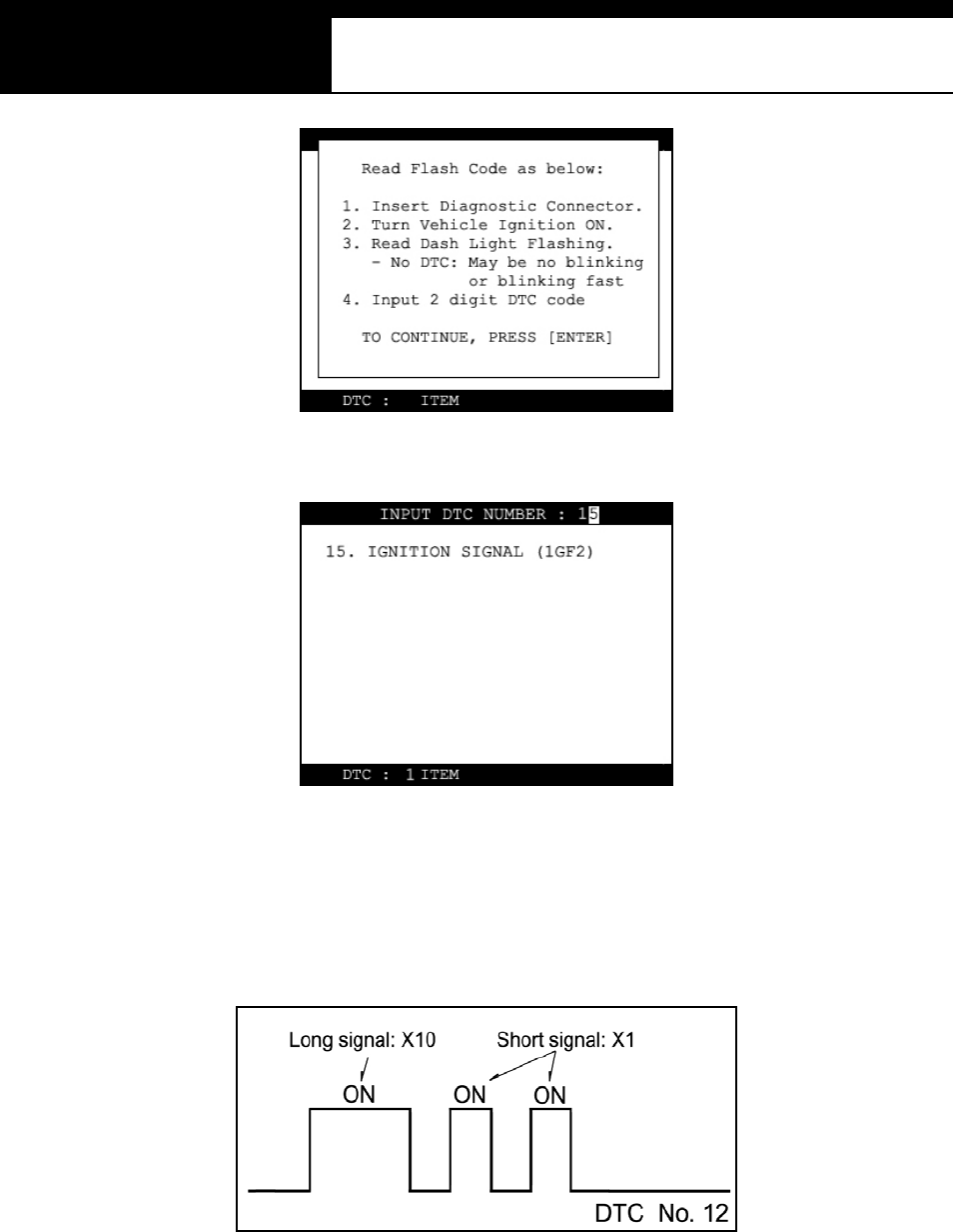
1. Pulse signa l type
a. Many of old Toyota, Honda, Mazda, Hyundai and Kia cars until early 90’s
support slow pulse signal output for the DTC reading function.
As shown below, Multiscan shows the pulse signal being received
through the DLC adapter in the top and the received DTC numbers.
b. Manual input
-Even older cars such as Honda with 2-pin adapter have no signal
output terminal for DTC in the DLC adapter. In this case, Multiscan
shows the following message as there is no signal input through the
adapter.
USER MANUAL For Multiscan
G
jG[GTG YG
-You have to count the MIL flashing on the dashboard and manually
input the DTC number to Multiscan to view the details as below:
-Long fl as h si gnals count for tens and short signals for ones . Input
two digits for tens and ones in sequence using the numeric keypad.
A flash signal for a code is followed by another if there are multiple
troubl e codes . Bli nki ng si gnals f or all troubl e codes flas h i n
sequence, and repeat after a pause.
c. Others
-Generall y Multis can reads DTC puls e signal from the di agnosti c

Han atech Co., Ltd. Chapter 4
G
jG[GTG ZG
adapter and shows the DTC number, title and details automatically.
2. Serial Communication type
a. Most of the cars built in 1990’s or later support serial communication with
a scanner, and the DTC is read by bi-directional communication.
b. Multiscan sends a command to the control module to reply with the DTC
numbers stored in memory, and the control module replies thereupon.
USER MANUAL For Multiscan
G
jG[GTG [G
B. DTC Erase (Clear fault code )
1. Pulse signa l type
a. Puls e s ignal type does not s upport bi-di recti onal s eri al com muni cat ion,
therefore, a scanner is unable to send a command to the control module
to erase the DTC information from memory.
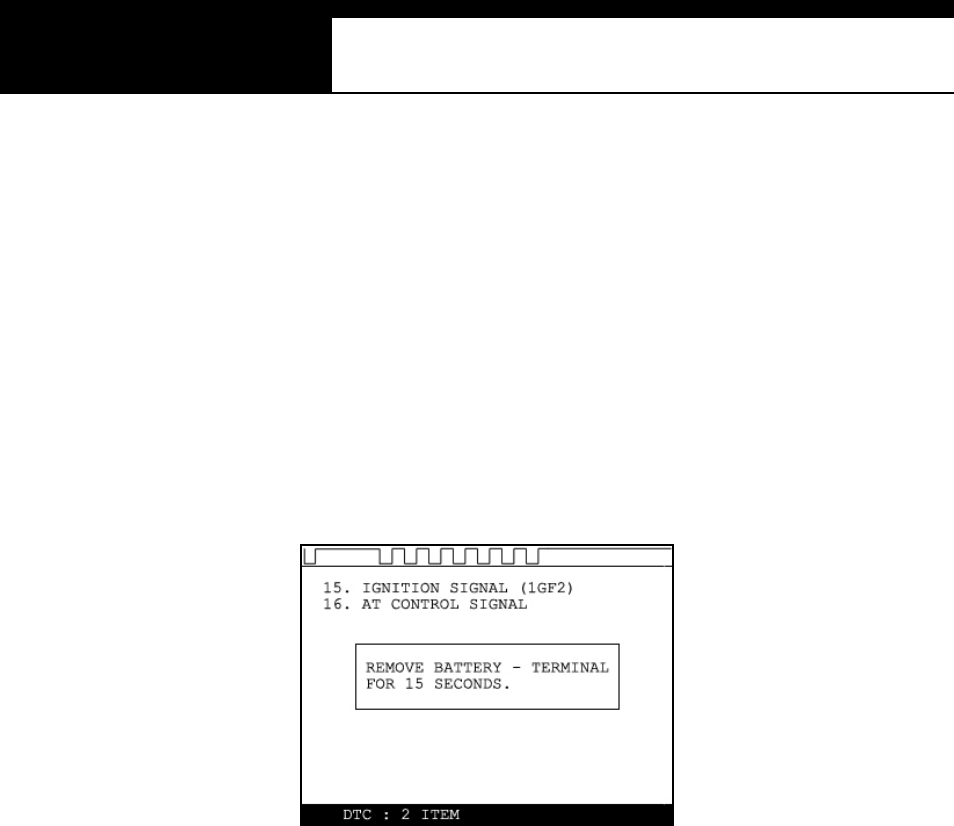
These old cars require you to remove battery terminal to clean up
diagnos ti c informati on f rom control m odule memory.
Removing the battery terminal will get rid of all information contained in
the car stereo and other electronic devices. And it may not effectively
erase the fault codes in some cars. Refer to the original repair manual
for further information.
Check if DTC information is properly rem oved by reading the trouble
code again after erasing the code.
2. Serial communicatio n type
a. Multiscan sends a command to the control module to erase DTC
information stored in memory, and the control module replies thereupon.
b. Check if DTC information is properly removed by reading the trouble
code again after erasing the code
Han atech Co., Ltd. Chapter 4
G
jG[GTG \G
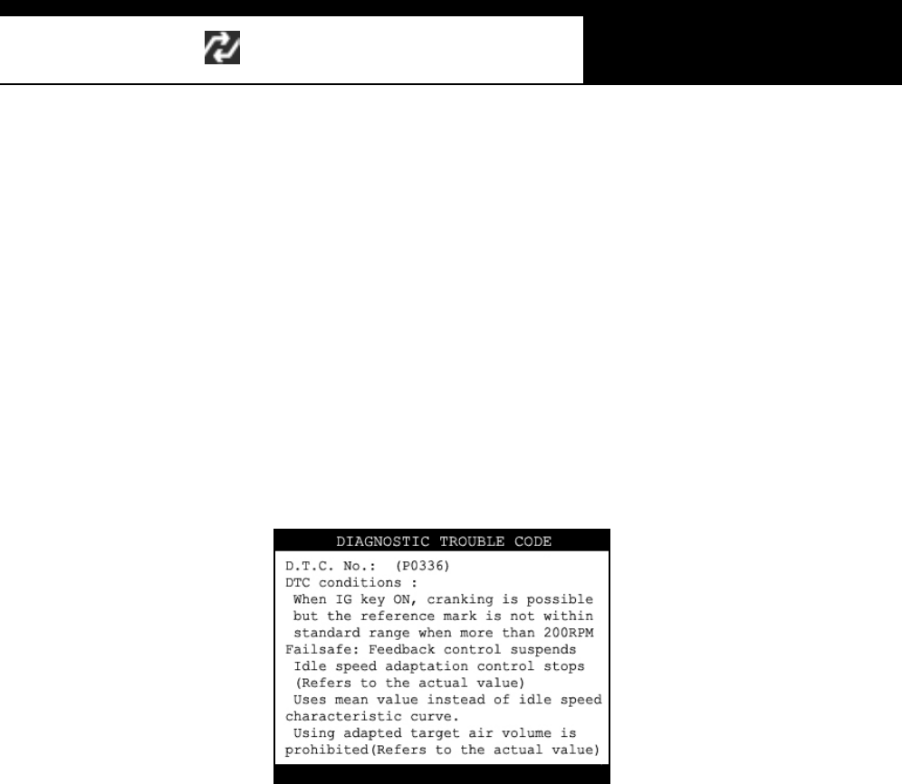
C. DTC Help tips
a. Help tips are provided when you press the [HELP] key after locating the
highlighted bar on one of the detected trouble code(s). This function is
available when Multiscan detects one or more trouble code(s)
b. Help tips including trouble code definition, conditions and check points
are provided for all Korean cars and Malaysian cars as of May 2003.
Wiring diagrams are also provided for Korean cars of 2000 model-year or
older.
c. Press the [ESC] key to return to DTC list.

USER MANUAL For Multiscan
G
jG[GTG ]G
II. Current Data -----------------------------------
(= Da ta S tream, Live Da ta, Service Da ta )
A. Pulse Signal Type
a. Data stream is not generally supported for this type of old cars because the
s peed of puls e signal com munication is too sl ow to read the data st ream
variables .
b. Some of old Toyota cars using 17-pin rectangular adapter exceptionally
support data readings as the system supports relatively high speed pulse
signal comm uni cation.
B. Serial Communicatio n Type
a. Most of control systems with serial communication support data stream
function. Sel ect [C urrent data] from the menu, then the data readings follow.
b. Some systems like SRS or ABS may be designed not to support data stream
on purpose by the car manufacturer while the other systems are supported.
A scanner is a passive tool that reads inform ation from the control system,
and it is unable to actively generate information that the system does not
provide.
c. Some old OBD1 generation Korean and European cars equipped with Bosch
control system that communicates in ISO9141 protocol provide relatively
slower communicati on s peed. Data s ampling may seem slow with these
cars
Han atech Co., Ltd. Chapter 4
G
jG[GTG ^G
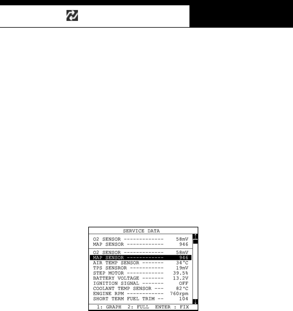
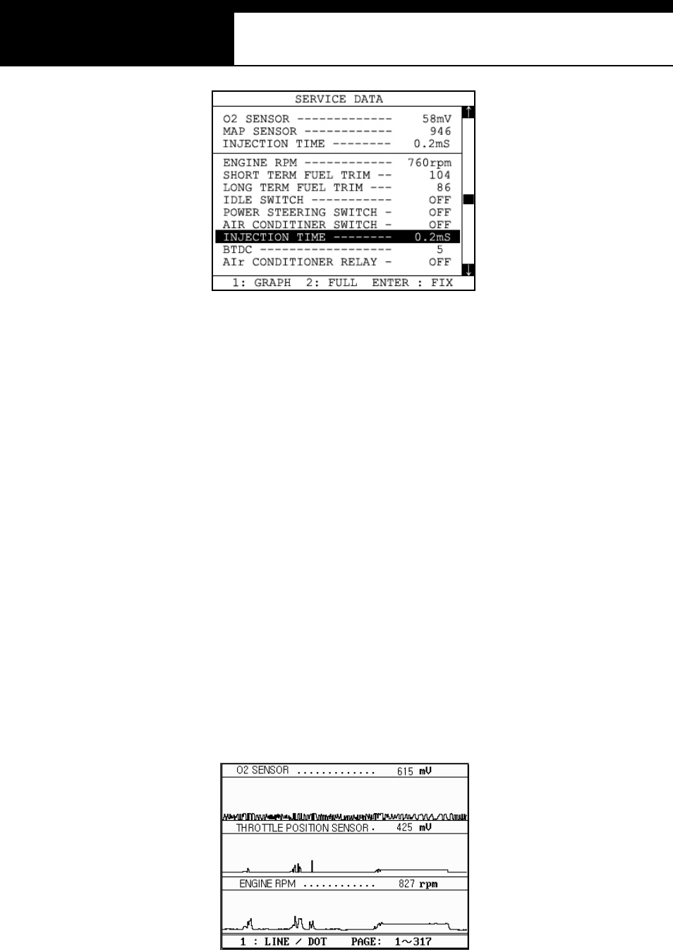
C. Data Freeze
The [Data Freeze] function places the selected data stream variable on top of
the LCD screen so that the user can check and compare desired sensor
values continually without having to scroll up and down.
This i s different from ‘Freeze Fram e Data’ function of Generic OBD2.
1) Step One
Select a desired sensor using the [ൖ][൘] and the [][] keys.
2) Step Two
Press the [ENTER] key to freeze the selected sensor.
i.e., when O2 sensor and MAP sensor are selected and frozen, these
sensor values will be placed at the top of the display as below :
3) Step Three
Up to five sensors may be frozen at a time. For example, if the Injection
Time, which can be shown when scrolled down, is selected and frozen,
Injection Time value will be placed below the previously frozen O2 and MAP
sensor.
USER MANUAL For Multiscan
G
jG[GTG _G
D. Data Graph
Multiscan provides the [Data Graph] function for more efficient data
an alysis .
a When you press the [1] key after locating the highlight bar on the desired
sensor, the sensor data graph will be displayed as shown below.
b You can display up to 3 graphs in a screen by choosing the sensors as
previously explained [Data Freeze] procedure - Press the [Enter] key
after locating the highlight bar on the desired sensor, and then press the
[1] key. When more than 4 sensors are selected, the graphs of upper
three sensors will be displayed.

Han atech Co., Ltd. Chapter 4
G
jG[GTG `G
c For each sensor data graph, the name of the sensor and its current
value will be simultaneously displayed together.
d To change the sensor, go back to the previous Service Data display by
pressing the [Esc] key, and then choose other sensors.
e To halt the graph output, press the [ENTER] key. It will resume when
you press the [ENTER] key again.
USER MANUAL For Multiscan
G
j G[G TGXWG
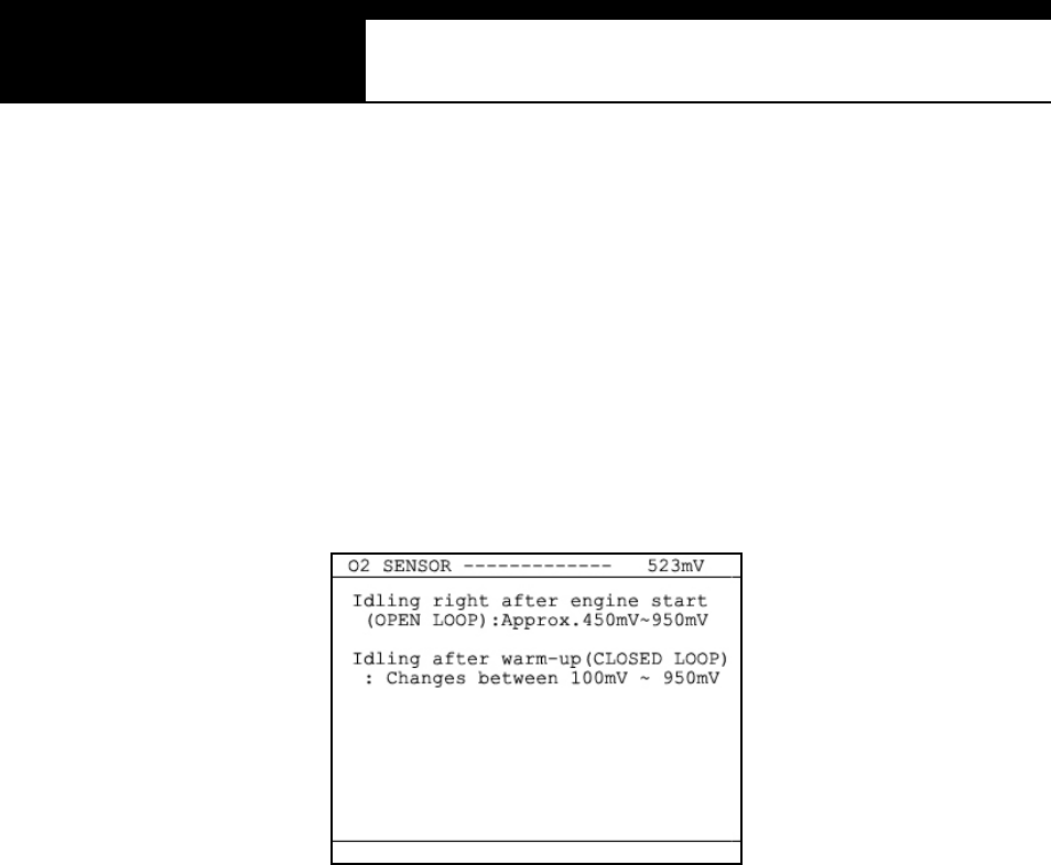
E. Help tips
a When you press the [HELP] key after locating the highlight bar on a
certain data stream variable, the help message will be displayed. This
works the same for detected Trouble Codes in [Self Diagnosis] function.
b Detailed information including conditional standard range on the selected
sensor will be displayed as shown below.
c Press t he [ESC ] key to go back to the data s tream dis pl ay.

Han atech Co., Ltd. Chapter 4
G
j G[G TGXXG
III. Actuation Test ---------------------------------
-The actuation test is a very helpful function that temporarily activates
or stops a certain actuator such as an injector, a motor or a solenoid
by force, so that the user can evaluate the system's condition or the
part’s normal operation by observing its reaction
-Signals from various sensors are input to a control unit, and the
actions are taken by controlling to actuators. Sensors and
actuators are causes and effects in a control system.
-While the data stream function is useful to observe if the sensors are
working properly and the control unit is collecting correct data from
the sensors without problem, the actuator test is helpful to examine if
the actuators are working in normal conditions and the control unit is
commanding proper control over the system.
-Some of the cars such as Nissan or Toyota provide even more
advanced actuation tests by letting the user observe the reaction of
overall control system when manually adjusting the sensor input
va l u es .
USER MANUAL For Multiscan
G
j G[G TGXYG
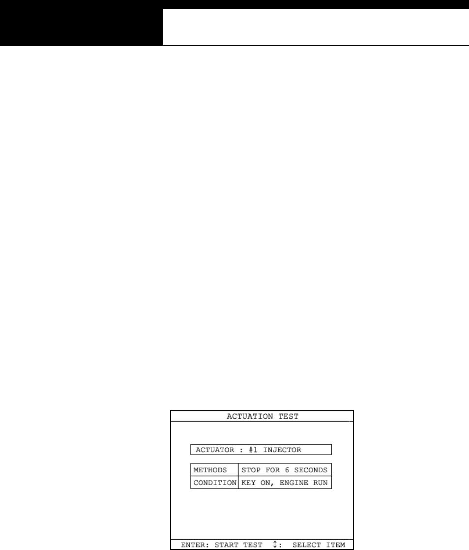
A. Menu Selection
a Choose [ACTUATION TEST] from the function Selection Menu
b The name of the actuator to be tested, test method and the test condition
are shown in the display. Available actuators, test methods and
condi tions m ay di ffer in each vehi cl e.
B. Test S ta r t
1. Selecting Test Item
a Choose an actuator to test from the menu by using the [] and [] keys.
b Check the test conditions and press the [ENTER] key when all the
conditions are met.
2. Testing
a [TESTING...] message will be displayed during the actuation test
Test method means how the actuation test will be performed. Check
the actual reaction of the actuator
b In the example below, the injector will stop injecting fuel for 6 seconds
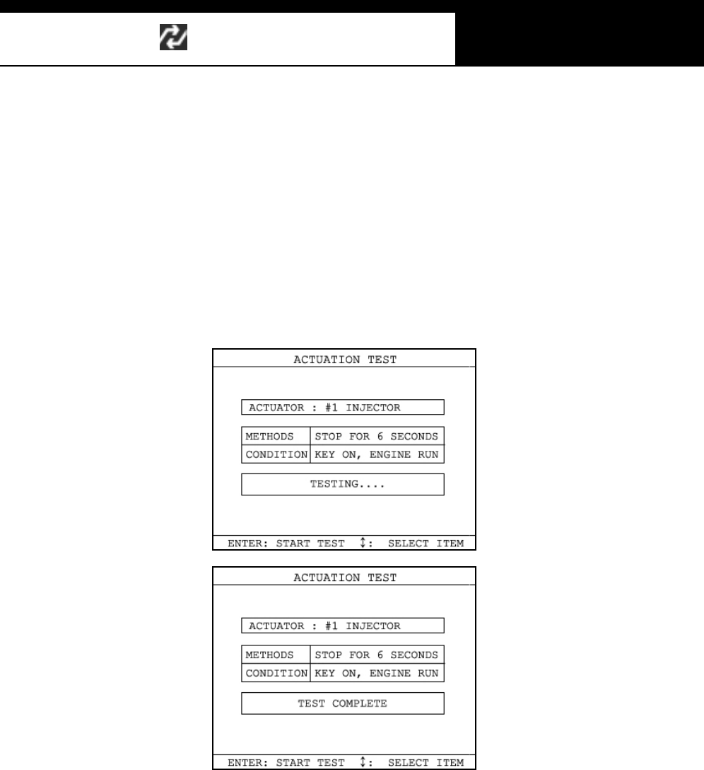
Han atech Co., Ltd. Chapter 4
G
j G[G TGXZG
while engine is idling, and it will make engine stall or unstable.
c Testing a fan or an injector is easy to check the proper reaction as it
generates distinctive changes in vehicle condition such as fan whining or
unstable idling. However, valves or motors are generally tested while
engine is stopped and all you can hear may be a small and unclear
electric buzzing sound. Test in a quite place and observe the test
results carefull y.
d When the test is completed, the [TEST COMPLETE] message will be
displayed. You can choose other actuators by using the [] and []
keys. Press the [ESC] key to quit test mode.
USER MANUAL For Multiscan
G
j G[G TGX[G
ٻ
IV. Black Box --------------------------------------
Just like the 'Black Box' or a ‘flight recorder’ of an aircraft, Multiscan can
'record' data stream during the vehicle drive test and the recorded data can
be 'retrieved' later for intensive analysis of vehicle's condition.
A. Func tio n sele ctio n
Choose [#. Black Box D ata] from the [Function Selection Menu] after
selecting Origin, Car Manufacturer, Model name and system to test.
Han atech Co., Ltd. Chapter 4
G
j G[G TGX\G
B. Capacity
a Duri ng a norm al tes t, the [Data Stream ] frames pass by in rapi d
s uccessi on, and cannot be recalled unl ess the data has been s aved.
Thanks to its extensive internal memory, Multiscan can record up to
2040 frames of Data Stream for multiple cars.
b By loading the recorded data, you can diagnose sensor data frame to
frame without missing a single cri tical moment.
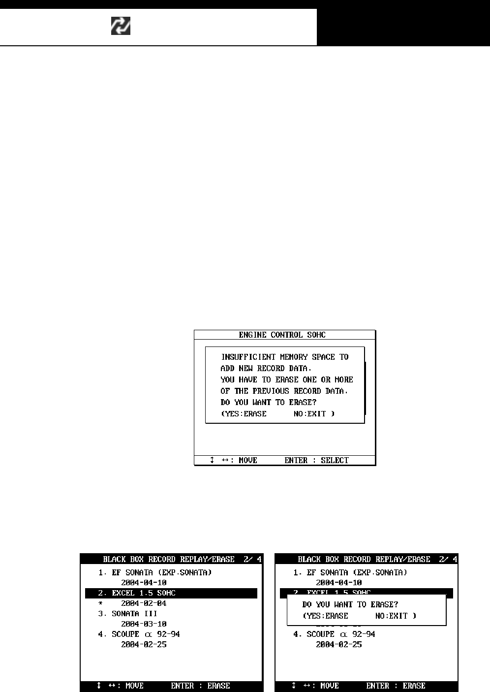
B. Memo ry Check
a. Multiscan checks its internal memory before it starts recording Black Box
data. If there is no sufficient free memory space available, Multiscan will
suggest deleting one or more of previous record(s).
b. Press the [ERASE] key to proceed, then a list of saved data will follow.
Locate the highlight bar on data to delete, and press t he [EN TER ] key.
A query for your confirmation will follow. Press the [YES] key to erase
otherwise press the [NO] key.
USER MANUAL For Multiscan
G
j G[G TGX]G
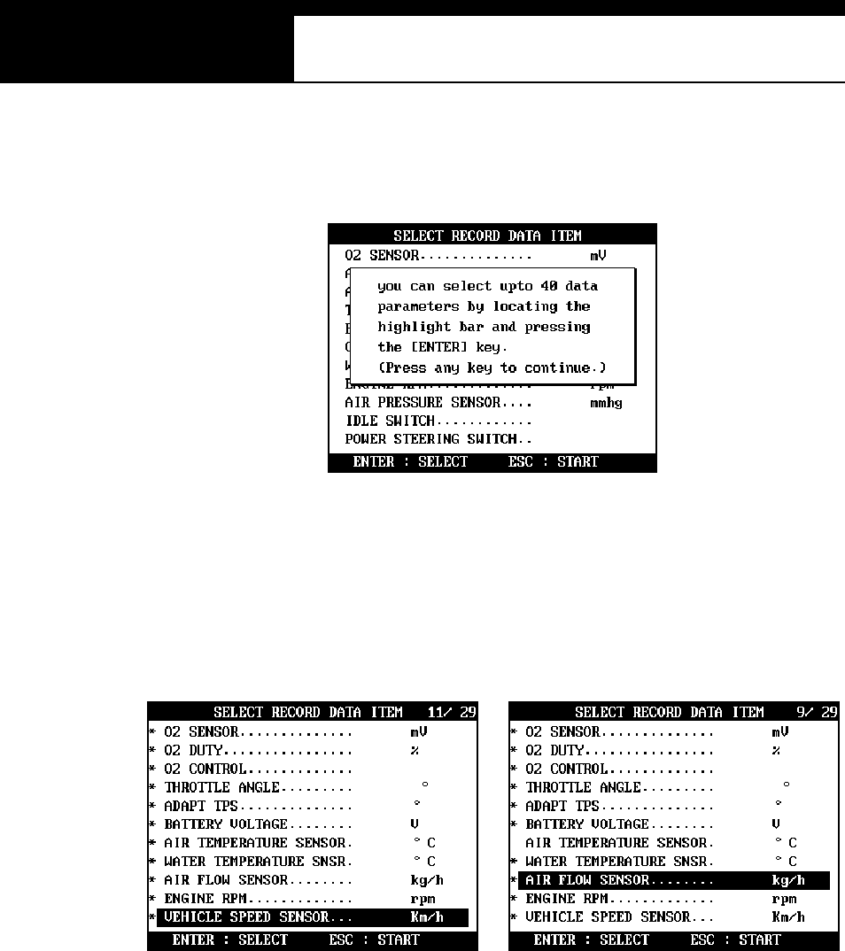
C. PID(Live data parame ter) selection
a You are required to s el ect the param eters to record.
b Multiscan will show you the whole live data parameters available in the
control system you selected. Locate the highlight bar on the desired
parameter and press the [ENTER] key.
Selected parameter will be marked star(*).
You can also deselect the parameter by repeating the procedure.
c You can select up to 40 PIDs to record. Press the [ESC] key when the
selection is completed, then Multiscan will start recording data.
Han atech Co., Ltd. Chapter 4
G
j G[G TGX^G
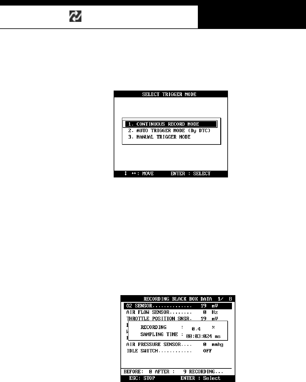
D. Trigger Modes
There are three trigger modes in the black box function.
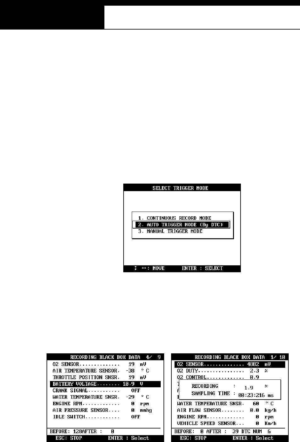
a Continuous Record Mode (No trigger m ode)
-Multis can will record li ve dat a of s elect ed parameters up to 2040
fram es or until you press the [ESC] key.
-Percentile memory usage and sampling time(frequency) will appear
in the center of the screen while recording data, and the actual live
data values will remain unchanged.
-Since no DTC trigger is applied in this mode, number of “Before
DTC” frames will remain 0, and the “After DTC” will keep increasing
as the more frames are recorded.
USER MANUAL For Multiscan
G
j G[G TGX_G
b Autom atic Trigger Mode (Triggered by DTC)
-Multiscan will keep recording live data of selected parameters up to
128 fram es .
-Once a DTC is detected or the [ESC] key is pressed by the user, it
will proceed with recording remaining frames up to 2,040 or until you
abort.
-This function will let you have a set of data stream before and after
the ECM’s DTC recognition when you perform the test drive.
-Before DTC, you will see the Live Data of the selected parameters
keep refreshing, however, once triggered by DTC or [ESC] key
stroke, only the percentile process information and sampling
frequency will be displayed.
Han atech Co., Ltd. Chapter 4
G
j G[G TGX`G
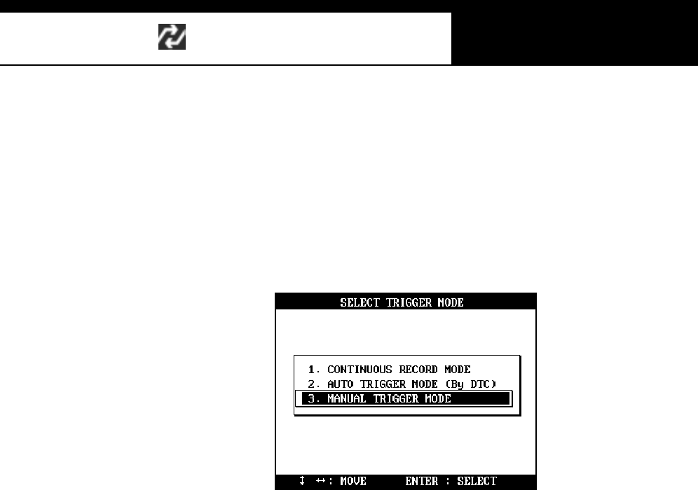
c Manual Trigger M ode
-Multiscan will keep recording live data of selected parameters up to
128 frames, and once the [ESC] key is pressed by the user, it will
proceed with recording remaining frames up to 2040.
-The s creen dis play is t he sam e as when selecti ng the Auto Trigger
Mode.
USER MANUAL For Multiscan
G
j G[G TGYWG
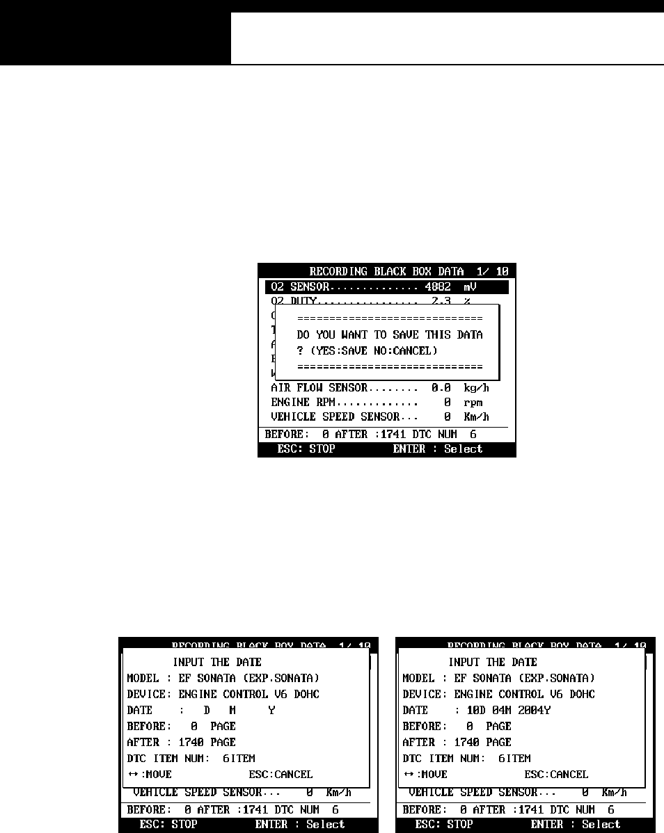
E. Saving the recorded data
a When the total frame number reaches 2040 or when you press the
[ESC] key to abort, a query asking you if you would like to save recorded
data or to discard it. Press [YES] to save or [NO] to cancel.
b When pressed [YES], a dialog box follows and asks you to input the test
date. Enter the date and press the [ENTER] key to save the recorded
data to Multiscan memory.
Pressing the [ESC] key cancels saving data.
Date form at is DD-MM-YYYY(D-day, M-month, Y-year), and only
numeric values are available.
c Tested Vehicle model name and control system will be saved as well as
the date s tamp for future retri eval .
Han atech Co., Ltd. Chapter 4
G
j G[G TGYXG
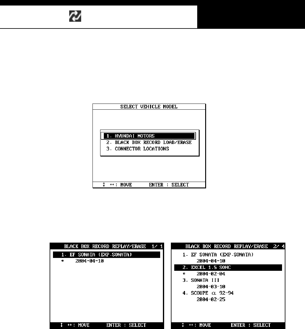
F. Black Box Da ta Load
a You can load saved data by choosing [BLACKBOX RECORD LOAD /
ERASE] from the [Car Manufacturer Selection] menu as shown below:
b A list of recorded Black Box Data will follow for your selection
Up to 4 back box data can be stored in the memory per car manufacturer,
therefore, up to 4 saved black box data can be listed in the menu.
c The details of recorded data will be displayed for confirmation. If the
record is correct, press the [ENTER] key. Press the [ESC] key to abort.
d If you want to erase any of these saved data, locate the highlight bar and
press the erase key.
USER MANUAL For Multiscan
G
j G[G TGYYG
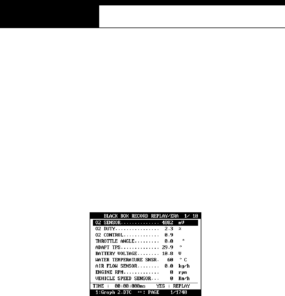
G. Loaded Blackbox data
Loaded black box data has basically the same form at as the [Service
Data (Live Data Stream)]. See the illustration below.
1. Data forma t
In the lower part of the display, the total number of recorded frames, frame
number before and after the DTC(Diagnostic Trouble Code), and the number
of DTC detected is displayed. In the example below, you can see that a
total of 458 frames were recorded, and data stream currently shown in the
mai n window is of the 336th fram e f rom the beginning. It als o tells you that
the current frame is the 80th after 2 trouble codes were detected.
The live data values m ay not be realis tic as the s creen was
captured while the scan tool was linked to a simulator.
2. Data Replay
a. Press the [YES] key then the saved blackbox data will start replying
Multiscan preserves the refresh time intervals of Black Box data.
Therefore, Black Box data is replayed at the same speed as when it
w as origi n all y re co rd ed .
Han atech Co., Ltd. Chapter 4
G
j G[G TGYZG
b. If you want to go forward or backward faster, press the [ൖ] o r [൘]
key while replaying. Replay speed will restore to the original speed
w he n t h e k ey is r el e as ed .
c. Pressing the [YES] key will pause the replay. You can resume
replaying from the frame where it was paused by pressing the [YES]
key again.
d. Pressing the [NO] key will stop replaying. You can restart replay
by pressing the [YES] key again, but i t will s tart from the firs t frame.
USER MANUAL For Multiscan
G
j G[G TGY[G
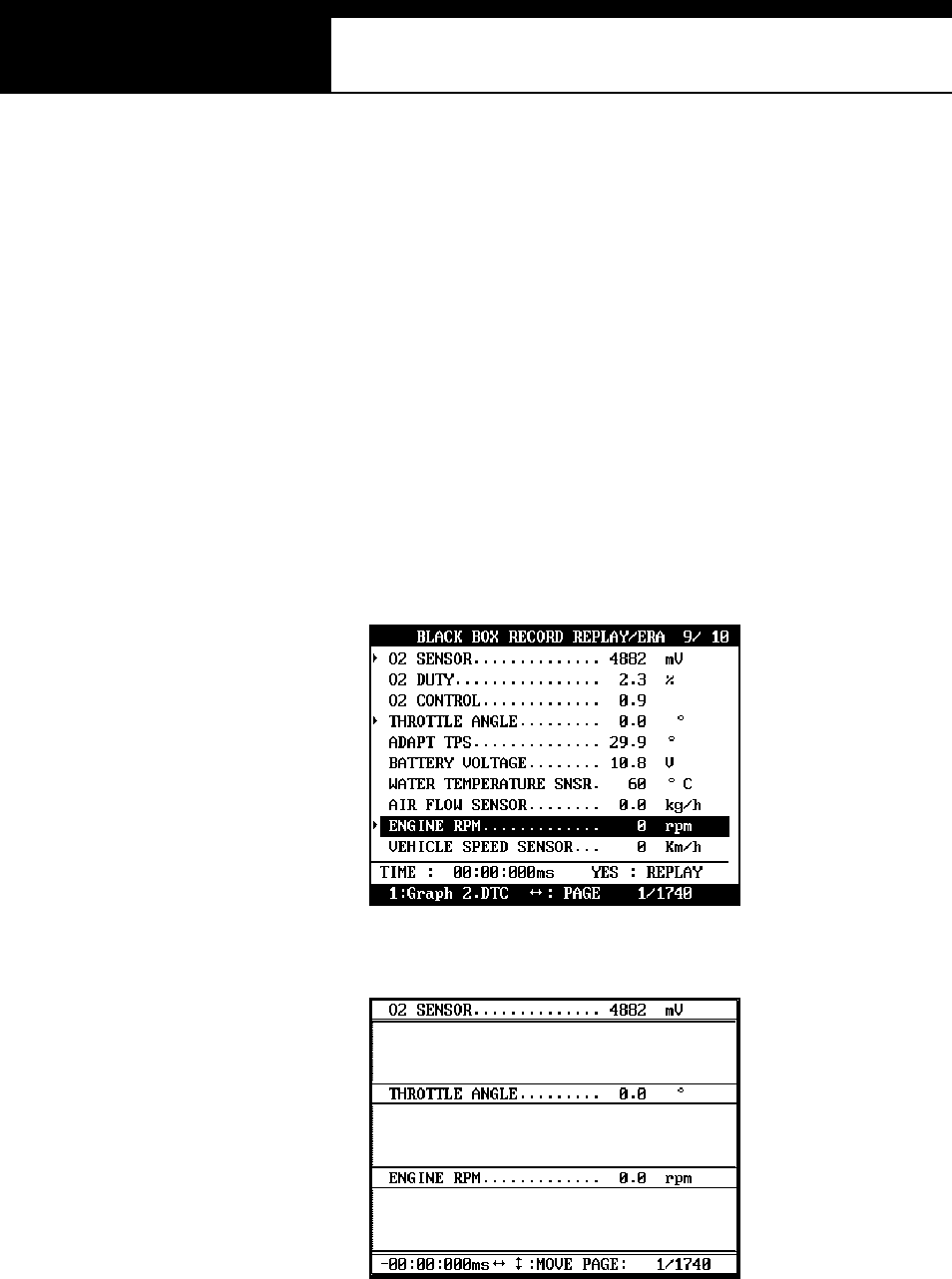
3. Graph
a As previously explained in section [3. Service Data], data from up to
three selected parameter data can be graphed.
b Make sure that the Black Box data replay is stopped. If it is being
replayed or paused, press the [NO] key to stop replaying completely.
c Choose the parameter by locating the highlight bar and pressing the
[ENTER] key. The selected parameter will be marked with a triangle as
shown below:
d Then press the [1] key to view the data in graph format.
The line graphs are flat as it is not based on
data recorded from the active vehicle.
Han atech Co., Ltd. Chapter 4
G
j G[G TGY\G
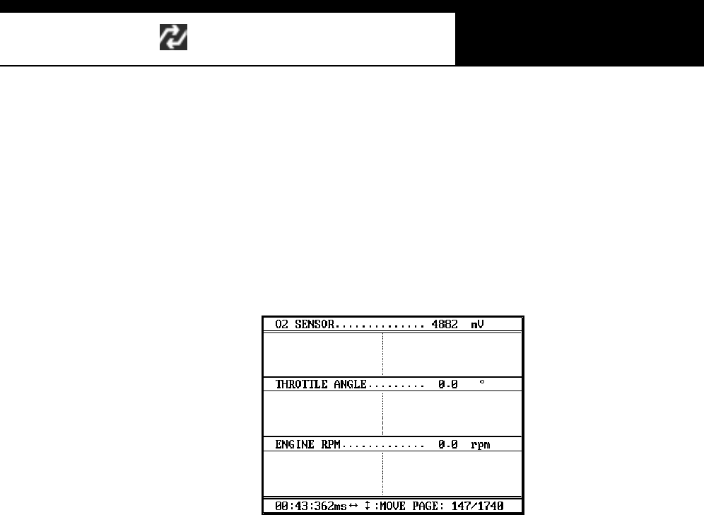
e Up to 316 frames can be displayed on a single page.
If recorded data has more than 316 frames, you can shift to next or
previous page by using the [] and [] k e ys .
f The dotted line indicates from which frame the live data parameter
val ues are bei ng displayed. You can m ove it left and right wi th the [ൖ]
and [൘] keys .
g Elapsed time and frame number are indicated in the bottom.
-Continuous Record (No trigger) Mode: Elapsed time and number of
fram es from the fi rst fram e
-Automatic / Manual Trigger (Triggered by DTC or user) Mode:
Elapsed time and number of frames from the trigger point (DTC
detection or [ESC] key stroke by the user). Before the trigger point
will be marked in negative values.
h To return to the Black Box Data Display, press the [ESC] key.
USER MANUAL For Multiscan
G
j G[G TGY]G
4. DTC
a You can check the DTC(s) found during recording Black Box Data.
b Make sure that the Black Box data replay is stopped. If it is being
replayed or paused, press the [NO] key to stop replaying completely.
c Press the [2] key then the list of DTC(s) will appear as below:
d Because Black Box Data is not live or active, you cannot erase DTC(s).
Han atech Co., Ltd. Chapter 4
G
j G[G TGY^G
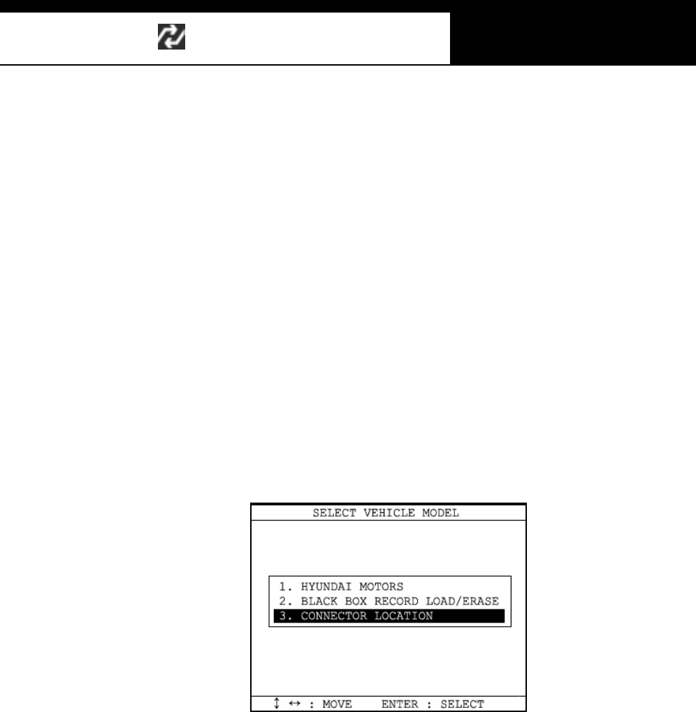
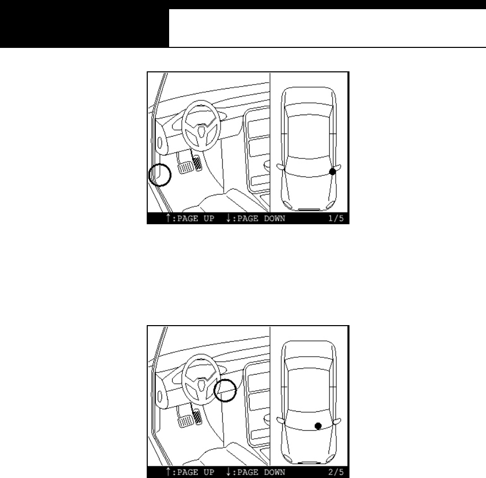
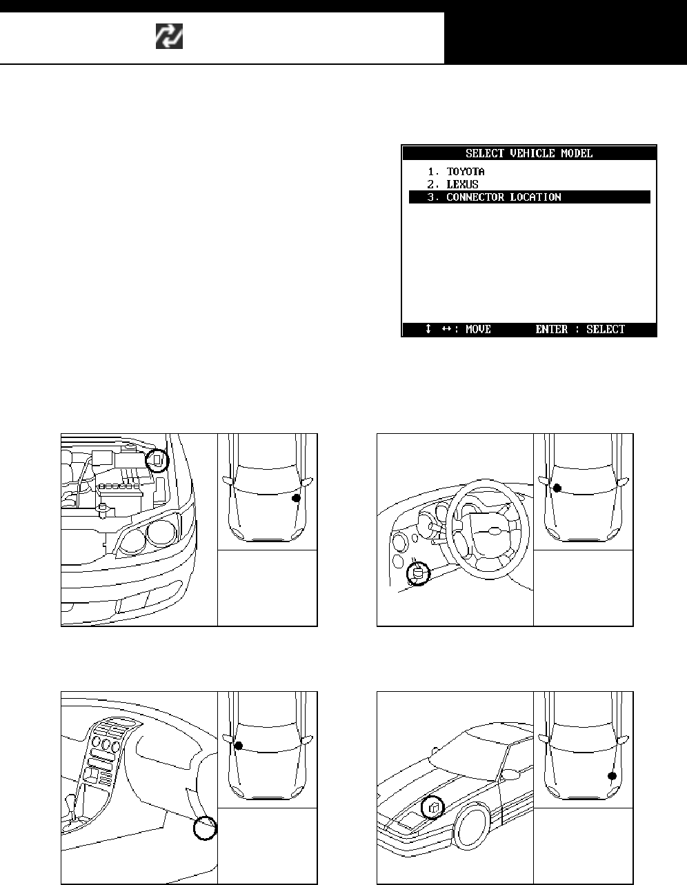
V. Connector Location ---------------------------
a The vehicle side OBD2 adapter is easy to find as the location is quite
regular – under the dash, however, the old vehicle side DLC adapters of
OBD generation 1 are located quite randomly and sometimes it is very
difficult to find.
Multiscan has the vehicle side adapter location maps for each car make
to aid the user in locating the adapters.
The locations suggested in this function are purely from Hanatech’s
experience, therefore, it may contain incorrect information. It is always
highly recommended to refer to the original repair manual published by
the car manufacturers for correct information.
G
b Select [CONNECTOR LOCATION] from the vehicle selection menu if the
adapter is not found in the place where it is supposed to be.
A drawing indicating the location of the vehicle side adapter follows. In
the right bottom of the display, the total number of location maps for the
selected car make is indicated. The example below is when Hyundai
motors is selected, and it tells there are total 5 maps.
USER MANUAL For Multiscan
G
j G[G TGY_G
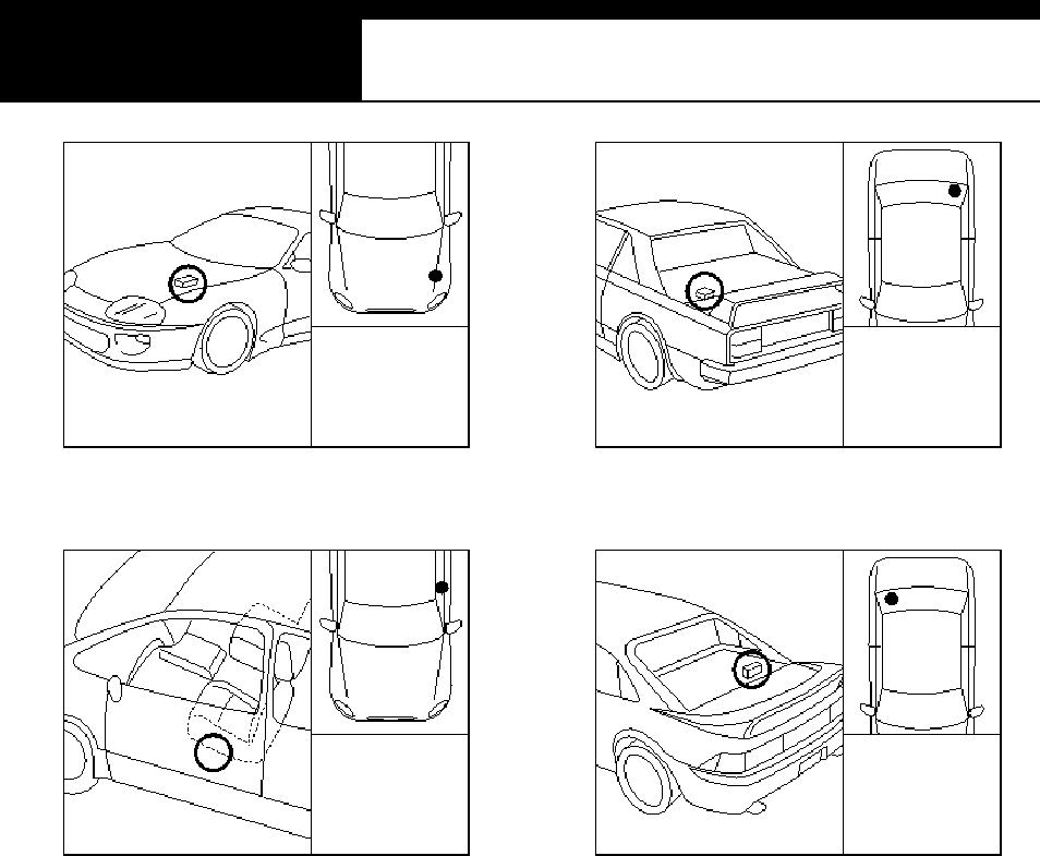
c The maps are provided in the order of most frequently found location.
Press Up or Down key to view the next or previous map. Press the
[ESC ] key to return to vehicle s election menu.
d Location maps for Korean cars are based on Left Hand Drive vehicles,
and the others such as Japanese, Australian and Malaysian cars are
based on Right Hand Drive cars. You may have to consider reversed
image according to your local practice.
Refer to each car make section in this manual for further information.

G
G
ٻ
ٻ
ٻ
ٻ
CHAPTER 5 GENERIC OBD2
I. LITERAL DEFINITION OF OBD2 …………. 5 – 1
II. MORE PRACTICAL NOTES …………. 5 – 2
A. Technical meaning of OBD2 5 – 2
B. Generic and Enhanced OBD2 5 – 3
III. Multiscan and OBD2 …………. 5 – 5
G

Han atech Co., Ltd.. Chapter 5
G
jG\GTG XG
Generic OBD2
G
I. Literal definition of OBD and OBD2-------
OBD is an abbreviation for On Board Diagnostics. OBD-1 is in reference to
Title 13 California Code 1968 titled "Malfunction and Diagnostic System for
1988 and Subsequent Model Year Passenger Cars, Light-Duty Trucks, and
Medium -Duty Vehicles with Three-Way Catalyst Systems and Feedback
Control." filed on 11-15-85. This required cars sold in California to have an
on-board computer processor for on-board self-diagnostics of computer
sensed emission related components, fuel metering device and EGR
(exhaust gas recalculation system). A partial or total malfunction that
exceeded exhaust emission standard would illuminate a MIL (malfunction
i ndi cator li ght) and provi de on-board identi ficati on of the m alfunction
location. To provide malfunction location information, codes are stored in on-
board computer memory. To read codes manufactures use methods, such
as flashing MIL light or various serial data protocols.
OBD-2 is in reference to Title 13 California Code 1968.1 titled "Malfunction
and Diagnos ti c System Requirements -1994 and Subsequent Model-Year
Pass enger Cars, Light-Duty Trucks, and Medium -Duty Vehi cl es and
Engines . Filed on 8-27-90 to Air Res ouce Board (ARB)
This requires a standard electrical connector, open source standardized
diagnostic trouble codes (DTC), data, and communication protocol with more
specific self-diagnostic on-board monitoring of emission malfunctions.G

USER MANUAL For Multiscan
G
jG\GTG YG
II. More practical notes --------------------------
A. Technical meaning of OBD2
1. Standardization
a For the technicians and scan tool engineers, OBD2 has its technical
meaning as bringing the standardized methods of vehicle diagnosis to
the chaotic afterm arket where dozens of car make use different
diagnostic adapters and communication protocols of their own.
b The 16-pin trapezoid diagnostic adapter and a few of most influential
communication protocols including ISO9141-2, KWP2000, and SAE
J1850 VPW and PWM form the standard OBD2 specifications.
c Trouble codes and Data stream variables were also standardized and
opened to public, so that all the s canners that support aforem entioned
standard communication protocols through the 16-pin OBD2 adapter can
always get the same readouts.
2. Purpose of OBD and OBD2
a. OBD and OBD2 are the names of regulation that were legislated in USA
for the emission control.
b. On board diagnostics was implemented to monitor malfunction or failure
of the emission related parts and components to minimize the possibility
of excessive exhaust gas emission by letting the driver know that the car
has a problem and the technician immediately perceive what is the
problem when any trouble is detected in the emission control system .
And OBD2 became effective later to increase the efficiency of OBD by
s tandardization.

Han atech Co., Ltd.. Chapter 5
G
jG\GTG ZG
B. Ge ne ric OB D2 and E nha nced OB D2
1. Generic OBD2
a. OBD2 was implemented for the emission control. Therefore, the
standardization is limited to powertrain system that is directly related to
emission control. It is not mandatory for the other systems such as ABS
and SRS
b. Not all the trouble codes and data stream variables are standardized,
also. A list of trouble codes and data stream variables that are closely
related to emission control are defined as OBD2 standards, however, it
also allows more codes and variables reserved for car make’s own
definition and usage. These standardized parts of trouble codes and
data stream variables are so called Generic OBD2. Generic OBD2
application is limited to emission related systems and so is the diagnostic
readouts
2. Enhanced OBD2
a. Generic OBD2 has limited availability for overall diagnosis, however, an
actual car has a lot more than this. The control systems other than
powertrain are not included in the mandatory OBD2 regulations, and
each car make has different trouble code and data stream definitions for
the reserved non-s tandard fields of powertrain s ystem.
b. The scope of on board diagnostic system that OBD2 standard features
do not cover is called Enhanced OBD2.
3. Manufac turer’s OBD
a. Many of Non-USA cars of 1996 model-year or later have an OBD2 16Pin
adapter, however the communication with scanners does not follow
standardized OBD2 protocols.
b. These car makes maintain their own communication features that are not

USER MANUAL For Multiscan
G
jG\GTG [G
much different from OBD generation 1 but only the appearance of
diagnos ti c adapter. This is s o cal led MO BD or manufacturer’s OBD.
c. With Multiscan, MOBD communication is supported for all car makes that
are included in the coverage list.
Han atech Co., Ltd.. Chapter 5
G
jG\GTG \G
III. Multiscan and OBD2 ------------------------
A. Ge ne ric OB D 2 i n M ul ti sca n
1. General OBD2
a You will find General OBD2 category in the initial menu.
b Selecting [2. Generic OBD2] will be followed by the diagnostic adapter
s ugges ti on. P ress the [ENTER] key to proceed.
c Multiscan then automatically tries to establish communication with the
powertrain control module using standard OBD2 communication
protocols in turn.
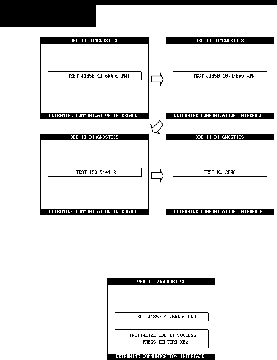
USER MANUAL For Multiscan
G
jG\GTG ]G
d When succeeded in communicating with the control module with any of
these 4 standard protocols, Multiscan reports the successful
establishment of communication and waits for your command to
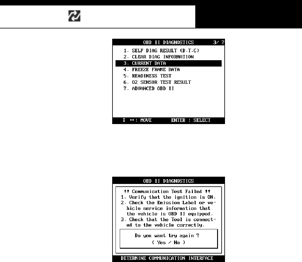
com mence generic O BD2 diagnos is as below:
e Available functions for the generic OBD2 system is listed as shown
below:
Han atech Co., Ltd.. Chapter 5
G
jG\GTG ^G
f In case the control module does not respond after t rying all OBD 2
standard protocols, Multiscan shows the failure report and check points
as below:
2. Whe n to se lec t
You may select this General OBD2 when you are sure that the test vehicle is
OBD2 com pliant but not included in the vehi cle coverage lis t .
3. EOBD
a Even though Multiscan does not include many European cars in its
coverage as of May, 2003, it is frequently reported that General OBD2 of
Mul tiscan works well wi th EOBD vehicles.
b In Europe, EOBD has become mandatory from January 1, 2001, and all
the cars built in Europe since then on must have been generic OBD2
compliant.
c You m ay select General OBD2 of Multiscan for the diagnosis of these
brand new European cars for the powertrain system.

G
G
ٻ
ٻ
ٻ
ٻ
CHAPTER 6 JAPANESE CARS
I. TOYOTA and LEXUS …………. 6 – 2
II. HONDA …………. 6 – 20
III. NISSA N …………. 6 – 31
IV. MITSUBISHI …………. 6 – 38
V. MAZDA …………. 6 – 50
VI. SUBARU …………. 6 – 56
G
Han atech Co., Ltd. Chapter 6
G
jG]GTG XG
Japanese Cars
-Multiscan software package for Japanese cars is provided as a part of 128MB built-
in flash m em ory.
-The Japanese car package contains a set of software comprising of the following
s oftw are groups.
9 TOYOTA / LEXUS USA
9 HONDA
9 NISSAN
9 MITSUBISHI
9 MAZD A
9 SUBARU
9 SUZUKI
9 ISUZU
9 Generi c OBD2
-Loading software
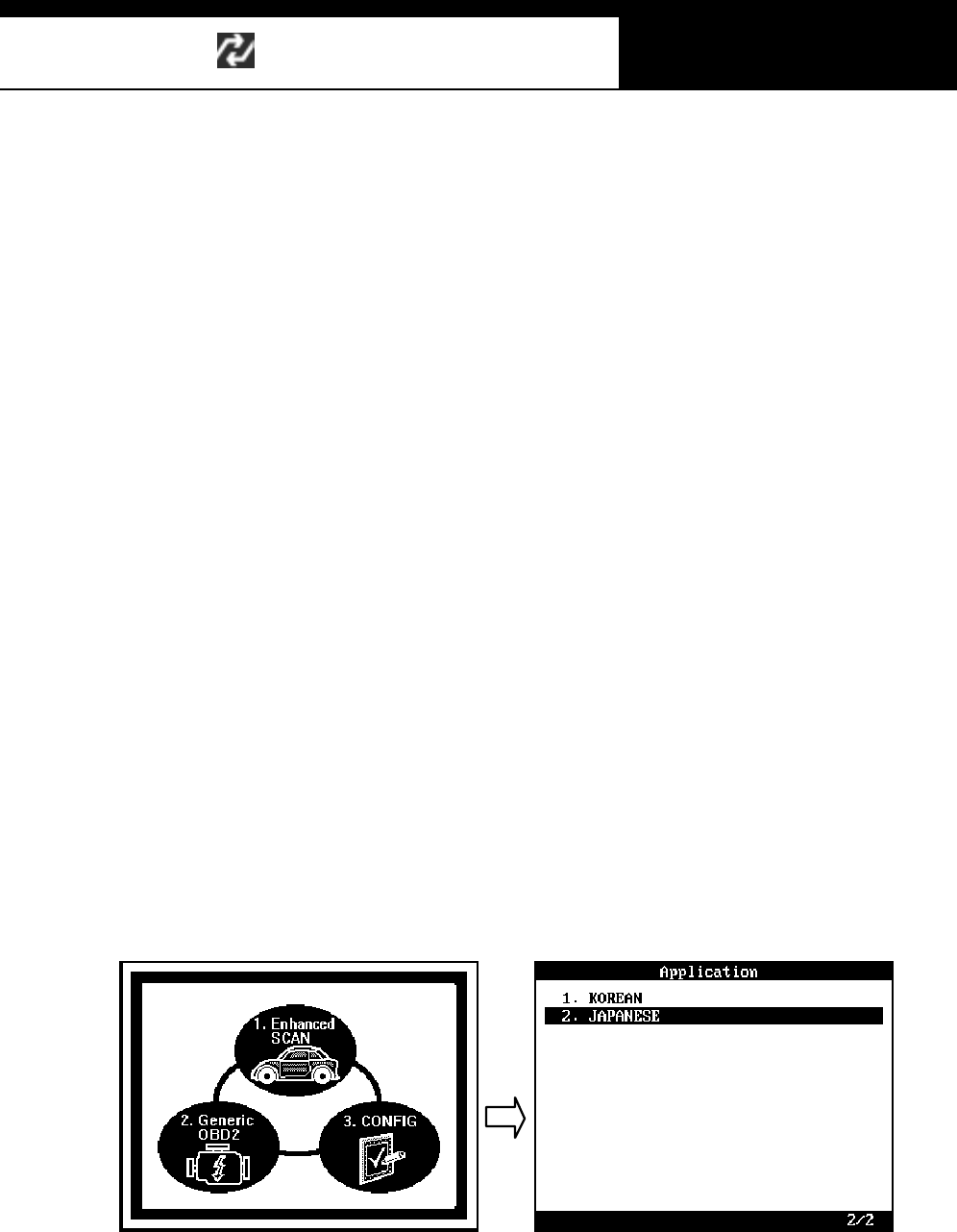
Select [1.SCAN] from the initial function selection, select Japanese cars, then the
lis t of Japanes e car makes will f ollow. The detailed m enu s el ection queries will
guide you to the correct diagnostic readouts.
USER MANUAL For Multiscan
G
jG]GTG YG
I. TOYOTA and LEXUS -----------------------
Toyota and Lexus cars share the same scanner communication methods
from a scanner’s viewpoint.
Multiscan does not separate Toyota and Lexus in the car make menu
because the detailed menu selection procedure and other features are
exactly same for both marques. You can select either Toyota or Lexus in the
next step.
This chapter covers Toyota cars. You can also refer to this section for
diagnosing Lexus cars.
A. Menu Selection
Toyota software of Multiscan follows the exactly same menu selection procedure as
the m anufacturer’s original equipment.
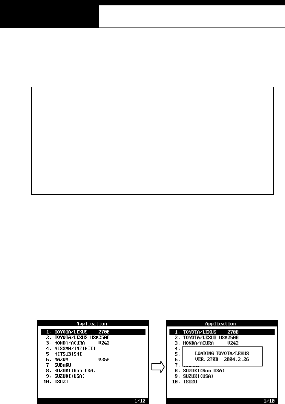
1. Select TOYOTA/LEXUS
Sel ect TO YO TA / LEXU S from the car make menu.
Han atech Co., Ltd. Chapter 6
G
jG]GTG ZG
2. Select Model Name
You can select between Toyota and Lexus at this stage.
Toyota non-USA version is applicable to all Toyota cars outside N orth
Am erica. It covers 32 di fferent model vari ants .
3. Select model cod e
You have to s el ect the exact m odel code of the vehicle model (i.e. MCV10,
MCV20, SXV10 and SXV11 for Camry)
Each model code represents a significant difference in overall system from
other model codes .
USER MANUAL For Multiscan
G
jG]GTG [G
4. Select model ye ar and other detailed model specifications
Multiscan may ask for your selection for a few more steps including model
year, manufacturing plant and the existence of O2 sensor or immobilizer
system to specify the exact vehicle details for precise and accurate results.
G
Han atech Co., Ltd. Chapter 6
G
jG]GTG \G
B. Why so complicated
The flow chart shows the menu selection procedure presented above for Camry
as an exampl e.
Many of aftermarket scanners have a very simple selection procedure for Toyota
cars by only s electi ng the di agnos ti c adapter type. Indonesian Tamaraw and Lexus
RX300 are considered same for these scanners.
However, the Toyota OE tool has a very detailed vehicle selection procedure up to
5 or 6 steps. The selection procedure of Multiscan is also designed to provide
reliable and diversifi ed diagnosis at OE tool level for each specific vehicle.
USER MANUAL For Multiscan
G
jG]GTG ]G
1. The difference of Toyota from the other Japanese cars
Japanese cars with the exception of Toyota and Nissan have ID check system.
A scanner communicates with an ECM to get the ECM ID number to identify
the test vehicle. Then automatically determines the appropriate communication
protocol accordingly.
However, Toyota has no such ID check system. To get the correct response, it
is absolutely necess ary to let the s canner know which car it is going to talk to.
Each vehi cle m odel code has different types of engine and control s yst em. Even
the number of sensors is different. To get full information that the vehicle ECM
transmits , the m odel sel ection m us t be as speci fi c as possibl e.
If a scanner starts communicating with the ECM after simply selecting the adapter,
the best result you can get is limited data for the generic items that are commonly
found in all Toyota cars.

Han atech Co., Ltd. Chapter 6
G
jG]GTG ^G
2. How to get the detailed specifications
a Model Code (Chass is number)
O pen the engine hood and fi nd the m odel code stamped i nto the vehicl e
specification tag, attached to firewall on the driver’s side.
b Model year and manufacturing plant
Model year and manufacturing plant information is contained in the
Vehicle Identification Number. Refer to the manufacturer’s manual
book for the details of VIN translation
c Equipped System
Some models may require you to confirm the existence of a certain
system like immobilizer or traction control. You can check this from the
warning lamps displayed in the dash panel right after turning the ignition
key ON.
3. [33. Others]
You will find this category in the end of the Toyota vehicle model list. You
may select this when you cannot find the model name in the list or when you
do not want to make selections for all the details.
Only the adapter type selection menu will follow, and then Multiscan will begin
to communicate with the ECM.
As mentioned above, it will work just like an ordinary aftermarket tool does,
and limited data for the common generic items will be available in this mode.

USER MANUAL For Multiscan
G
jG]GTG _G
4. Incorrect Ad apter
a No match in the list
Despite detailed vehicle selection procedure of Multiscan, you may
encounter a situation where you cannot find the correct vehicle details in
the list. If you s elect a similar vehi cl e model code or other details from
the menu, an incorrect adapter may be suggested.
For example, when you select AB-CD1 model code while the actual
vehicle is AB-CD2 which is not included in the list, Multiscan may ask
you to use 17 pin rectangular adapter even though the vehicle has the
17 pin semi-circular adapter.
The communication may fail in this case. You are recommended to
select [33. Others] to test the car in generic mode.
b Mul tiple adapters
If Multis can sugges ts to use a diagnostic adapter that is different f rom
the one that you found in the car, the suggested adapter may be found
elsewhere in the car.
Some Japanese cars have m ultiple DLC adapters, and generally each
of them covers different systems.
R efer to the adapter location maps below, and check the car for the
suggested adapter.
Han atech Co., Ltd. Chapter 6
G
jG]GTG `G
C. Func tio ns
1. 17 Pin Rectangular and Semi-Circular Adapter
a Diagnostic Trouble Code
-D TC readout is provi ded i n Flash code pulse signals for all s ys tems
when usi ng t his adapter.
-This old communication type does not allow bi-directional
communication between the scanner and the ECM. ECM simply
transmits the slow pulse signal when the appropriate DLC terminal
is grounded.
b DTC Erase
-Faul t code erase by a s canner is not available f or t he pulse signal
type communication.
-You m ust remove the (-) battery terminal to clear the fault codes.
Removing the battery terminal will get rid of all inform ation contained
in the car stereo and other electronic devices. And it may not
effectively erase the fault codes in some cars. Refer to the original
repair manual for further information.
c Data Stream
-Data Stream / Service Data / Live Data is supported for Engine only
for this type of adapter.
USER MANUAL For Multiscan
G
j G]G TGXWG
d Supported systems
-Rectangular Adapter: Generally only Engine and SRS systems are
s upported with this t ype of adapter.
For the other systems such as ABS, TCS and Cruise Control, only
the flash code manual reading is available by counting the relevant
Malfunction Indication Lamp blinking when the adapter is connected
to the vehicle side DLC.
-Semi-Circular Adapter: When the vehicle has 17 Pin Semi-Circular
adapter, all systems including Engine and SRS are supported
through this adapter.
2. 16 Pin OBD2 Adap ter
a Diagnostic Trouble Code
-Fault code read and erase are both
available when using the OBD2 adapter
-Neither manual flash code reading nor
battery terminal removal is necessary
for code read and erase.
b Data Stream
-Service data / Data stream / Live data is available for most systems
-Suspension and Cruise control systems of a few models may
s upport D TC pulse signal onl y. Data s tream is not available for
these exceptional models.
c Actuation test
-Actuation test is available for vari ous s ys tem s when usi ng this
adapter.
Han atech Co., Ltd. Chapter 6
G
j G]G TGXXG
D. Diagnostic Adapter Location
The DLC adapter location drawings are
purely from the experience of Hanatech and
provided for your reference only.
The drawings are based on Right Hand
Drive cars, therefore, you m ay have to
consider the mirror image for any Left Hand
Drive cars.
You can view these drawings on the Multiscan screen by selecting [3.Connector
Location] after selecting [2. Toyota / Lexus] from the car make list.
17 Pin Rectangular Adapter
16 Pin OBD2 Adapter
17P Semi-Circular Adapter
17 Pin Rectangular Adapter
USER MANUAL For Multiscan
G
j G]G TGXYG
17 Pin Rectangul ar Adapter
17 Pin Rectangul ar Adapter
17 Pin Rectangular Adapter
17 Pin Rectangular Adapter

HANA TECH CO., LTD. Chapter 6
G
j G]G TGXZG
E. Vehicle Coverage
Refer to the following coverage list.
(In Alphabetic order)
TOYOTA
MODEL CODE Supported System
4RUNN ER
KZN185
RZN180
RZN185
VZN130
VZN180
VZN185
ENGINE CONTROL
SR S AIR BAG
ANTI LOC K BRAKE SYSTEM
POWERTRAIN CONTROL MODULE
I MMOB ILISER
99L.O -- SRS AIRBAG
AVALON MCX10
MCX20
POWERTRAIN CONTROL MODULE
EC T
ANTI LOC K BRAKE SYSTEM
TRACTION CONTROL SYSTEM
I MMOB ILISER
CR UISE CONTROL SYSTEM
SR S AIR BAG
AVEN SIS
AT200
AT221
CT220
ST220
AZT220
CDT220
ZZT220
ZZT221
POWERTRAIN CONTROL MODULE
I MMOB ILISER
SR S AIR BAG
ANTI LOC K BRAKE SYSTEM
CAMRY
MCV10
MCV20
SXV10
SXV11
SXV20
VSV10
POWERTRAIN CONTROL MODULE
EC T
CR UISE CONTROL SYSTEM,
I MMOB IL ISER, SR S AIR BAG
ANTI LOC K BRAKE SYSTEM
CARINA
AT190
AT191
CT190
ST919
ENGINE CONTROL
I MMOB ILISER
SR S AIR BAG

USER MANUAL For Multiscan
G
j G]G TGX[G
CELICA
AT180
AT200
ST182
ST184
ST185
ST202
ST204
ST205
ZZT230
ZZT231
POWERTRAIN CONTROL MODULE,
I MMOB ILISER
SR S AIR BAG
ANTI LOC K BRAKE SYSTEM
CENTURY GZG50
ENGINE CONTROL
AIR SU SPENSION,
CR UISE CONTROL SYSTEM
I MMOB ILISER
SR S AIR BAG, BODY C ONTROL
COASTER
BB50
BB58
RZB40
RZB50
POWERTRAIN CONTROL
ANTI LOC K BRAKE SYSTEM
CONDOR
LF6X,8X
RZF80
RXF85
ENGINE CONTROL
I MMOB ILISER
COROLLA
AE100
AE101
AE102
AE103
AE110
AE111
AE112
AE115
AE92
CE110
EE101
EE104
EE111
CDE110
NZE120
NZE121
WZE110
ZZE111
ZZE112
ZZE121
ZZE122
POWERTRAIN CONTROL MODULE
I MMOB ILISER
SR S AIR BAG
ANTI LOC K BRAKE SYSTEM
EMPS
HANA TECH CO., LTD. Chapter 6
G
j G]G TGX\G
CORONA
AT190
AT210
AT220
CT220
ST171
ST191
ST210
ST220
POWERTRAIN CONTROL MODULE
ANTI LOC K BRAKE SYSTEM
I MMOB ILISER
SR S AIR BAG
CRESSIDA --
ENGINE CONTROL
ANTI LOC K BRAKE SYSTEM
CR UISE CONTROL SYSTEM
EC T
CROWN
GS151
JZS133
JZS155
JZS175
POWERTRAIN CONTROL MODULE
CR UISE CONTROL SYSTEM
ANTI LOC K BRAKE SYSTEM
VSC , EC T, SR S AIR BAG
AIR CONDITIONING SYSTEM
I MMOB ILISER
BODY1/2/3, D/P DOOR , SLIDE ROOF, TILT &
TELESCO, METER, COMBINATION SWITCH
DYNA
RZU100
BU213
BU223
XZU300
XZU320
XZU330
XZU340
XZU342
XZU 4XX
POWERTRAIN CONTROL MODULE
ANTI LOC K BRAKE SYSTEM

USER MANUAL For Multiscan
G
j G]G TGX]G
HIACE
LH103
LH114
LH125
LXH12,22
LXH18,28
RCH12
RCH13
RCH18
RCH19
RCH22
RCH23
RCH28
RZH102
RZH103
RZH105
RZH109
RZH112
RZH113
RZH115
RZH119
RZH125
RZH135
RZH153
LH162
LH172
LH174
LH184
RCH29
RZH155
ENGINE CONTROL, POWERTRAIN CONTROL
MODULE, SRS AIR BAG, IMMOBILISER
LAND
CRUISER
FZ75
FZJ80
FZJ100
FZJ105
FZJ71,74
FZJ73
HDJ100
HDJ80
HZJ105
HZJ80
KDJ90,95
KJZ90,95
RZJ90
RZJ95
UZJ100
VZJ90,95
POWERTRAIN CONTROL MODULE
AH C
ANTI LOC K BRAKE SYSTEM
I MMOB ILISER
SR S AIR BAG
CR UISE CONTROL SYSTEM
BODY
POWER SEAT CONTROL SYSTEM
TILT & TELESCO
MIRROR
HANA TECH CO., LTD. Chapter 6
G
j G]G TGX^G
HILUX
LN14X
LN15X
LN16X
LN17X
LN19X
RN 106
RN 110
RN85
RXN142
RZN144
RZN149
RZN147
RZN148
RZN154
RZN168
RZN169
RZN173
RZN174
RZN193
RZN194
KZN165
KZN190
POWERTRAIN CONTROL MODULE
I MMOB ILISER
SR S AIR BAG
KIJAN G
KF72
KF82
RZF71
RZF81
ENGINE CONTROL
LITEACE
CR42
KR42
SR40
YR22,29
POWERTRAIN CONTROL MODULE
SR S AIR BAG
I MMOB ILISER
MR2 SW20
ZZW30
POWERTRAIN CONTROL MODULE
SR S AIR BAG
I MMOB ILISER
ANTI LOC K BRAKE SYSTEM
EH PS
SEQUENTIAL MT
PASEO EL54
ENGINE CONTROL
SR S AIR BAG
I MMOB ILISER
PICNIC CXM10
SXM10
POWERTRAIN CONTROL
I MMOB ILISER
SR S AIR BAG
PREVIA
TCR10,11
TCR20,21
ACR30
CLR30
POWERTRAIN CONTROL MODULE
SR S AIR BAG
I MMOB ILISER
ANTI LOC K BRAKE SYSTEM
CRUISE CONTROL MODULE

USER MANUAL For Multiscan
G
j G]G TGX_G
PRIUS --
POWERTRAIN CONTROL MODULE
EMPS
ANTI LOC K BRAKE SYSTEM
SR S AIR BAG
CR UISE CONTROL SYSTEM
I MMOB ILISER
RAV4
SXA10,11
ACA20,21
ZCA25,26
POWERTRAIN CONTROL MODULE
SR S AIR BAG
ANTI LOC K BRAKE SYSTEM
I MMOB ILISER
RAV4 EV -- SR S AIR BAG
SOLUNA(AFC) AL50 ENGINE CONTROL
SPACI O AE111
ENGINE CONTROL
SR S AIR BAG
ANTI LOC K BRAKE SYSTEM
STARLET
EP81
EP82
EP91
ENGINE CONTROL
I MMOB ILISER
SR S AIR BAG
SU PR A JZA80
ENGINE CONTROL
EC T
ANTI LOC K BRAKE SYSTEM
CR UISE CONTROL SYSTEM
SR S AIR BAG
TRACTION CONTROL SYSTEM
TAM AR AW KF80
RZF81 ENGINE CONTROL,
TERCEL EL51
EL53
ENGINE CONTROL
SR S AIR BAG
UN SER -- EN GINE CONTROL
YAR IS
ECHO
SCP10
NCP10
NC P11
NCP12
NCP13
NCP20
NCP21
NCP22
POWERTRAIN CONTR OL SYSTEM
EMPS
ANTI LOC K BRAKE SYSTEM
SR S AIR BAG
I MMOB ILISER
FREE-TRONIC
STOP&GO
ZACE
KF60
KF80
RZF84
RZF85
ENGINE CONTROL
SR S AIR BAG
HANA TECH CO., LTD. Chapter 6
G
j G]G TGX`G
LEXUS
MODEL CODE Supported Systems
ES300 MCV20
VC V10 POWERTRAINEMS, ABS, CC S, IMM, SRS
GS 300 JZS147
JZS1 60
POWERTRAIN, ABS/VSC, CCS, A/C, IMM, SRS, BODY,
BODY2, DOOR (D, P, RR, RL), SEAT, SLIDE ROOF,
TILT&TELESCO, METER
GS 430 U ZS161
POWERTRAIN, ABS/VSC, CCS, A/C, IMM, SRS, BODY,
BODY2, D OOR (D, P, RR, RL), SEAT, SLIDE ROOF, TILT,
METER , STEERING PAD
IS200 GXE10
POW ER TRAIN, ABS, CCS, A/ C , IMM, SRS , BO D Y,
METER , TDS
LS400 UCF10
UCF20
POWERTRAIN, ECT, AIR SUS, ABS, TRACTION, CCS,
A/C , IMM, SR S, SRS SID E
LS430 UCF30
POW ER TRAIN, AI R SU S, ABS/VSC , CC S, A/C , I MM, SR S ,
GATE W AY, B O D Y ( 1 ,2 ,3 , 4 ,5 ), D OOR (D , P, RR , R L ) ,
SEAT(D , P, ``RR, RL), REAR SEAT S/W, SLIDE ROOF,
TILT, METER, COMBI S/W, STEERI NG PAD, TDS ,
CLEARANCE SONAR, RAIN SENSOR
LX470 UZJ100
POWERTRAIN, AHC, ABS/TRACTION/VSC, CCS, IMM,
SRS, BOD Y, SEAT, TILT/TELESCO, MIRROR
RX300 MCU15
POWERTRAIN, ABS/TRAC/VSC, CC S, A/C, IMM, SRS,
BODY, DOOR(D, P, RR, RL), SLIDE ROOF, METER, TDS
SC430 UZZ40
POWERTRAIN, TIRE PRESSUR E WARNIN G, ABS/VSC ,
CCS, A/C, IMM, SRS.GATEWAY, BODY (2, 3, 4, 5), DOOR
(D , P), SEAT (D , P), RETRACTABLE HARDTOP, TILT,
METER, COMBI S/W, STEERING PAD, TDS
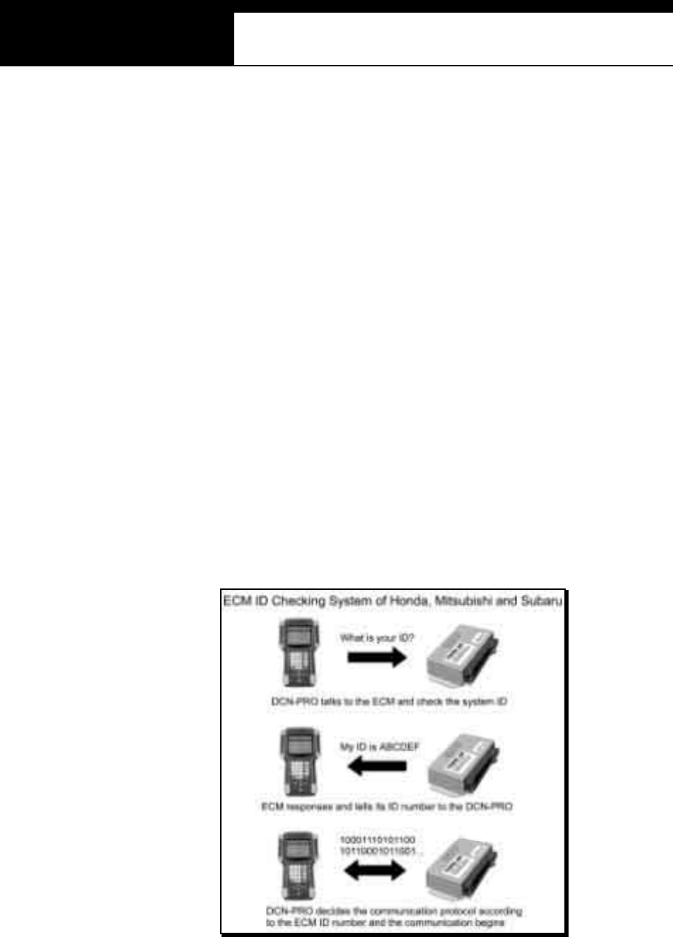
USER MANUAL For Multiscan
G
j G]G TGYWG
II. HONDA ----------------------------------------
A. Features of Honda S/W
1. Communicatio n Start-up
a Honda has the ECM ID check system.
Complicated menu selection procedure as in Toyota is not necessary for
Honda cars.
b The user is simply required to check the adapter type of the vehicle and
to select the adapter and the desired system to test.
c Then Multiscan automatically begins to talk to the ECM to identify the
system ID and determines its communication details according to the
response from the ECM.

HANA TECH CO., LTD. Chapter 6
G
j G]G TGYXG
2. Performance
a Multiscan HONDA software is applicable to all Honda cars regardless of
regional market and covers up to 4,000 different system IDs when
counting the Engine control system only. Total 7,000 IDs are included
in the database for all Honda car systems.
b Multiscan Honda software provides original equipment level reliability
and accuracy for Honda cars up to 2003 model year.
3. Difference
a It is very di fficult and time consuming to analyze al l the s ys tem IDs for
Honda cars. Most scanners provide only the limited readouts that are
commonly available in all Honda cars. Honda Civic and Acura Legend
are considered same for these scanners.
b Multiscan identifies each ECM version and provides the most optimized
and precise diagnostic inform ation of OE tool level.
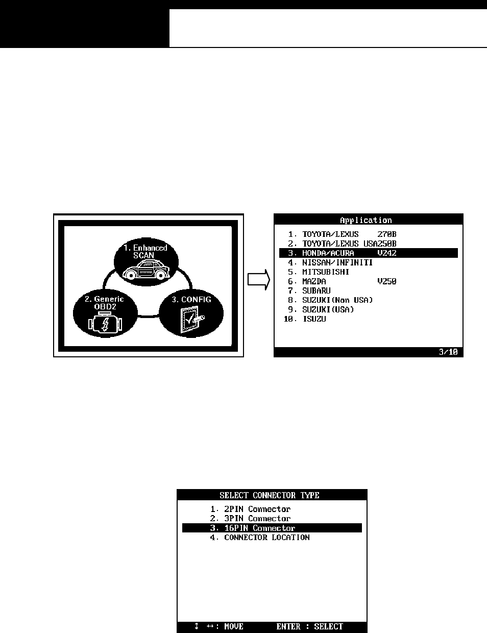
USER MANUAL For Multiscan
G
j G]G TGYYG
B. Menu Selection
1. Select HONDA/AC URA
Select HONDA /ACURA from the car make menu.
2. Select the adapter type
Search for the diagnostic connector in the car referring to the connector
location drawings hereinafter and select the connector type found.
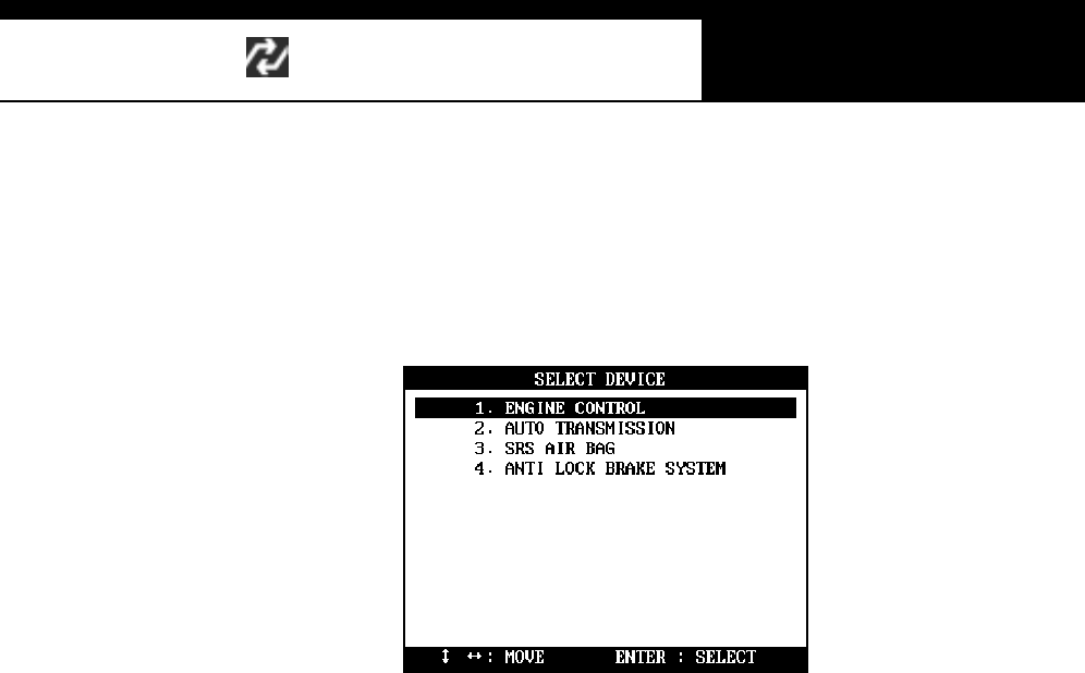
HANA TECH CO., LTD. Chapter 6
G
j G]G TGYZG
3. Select Test System
Select the system you want to test.
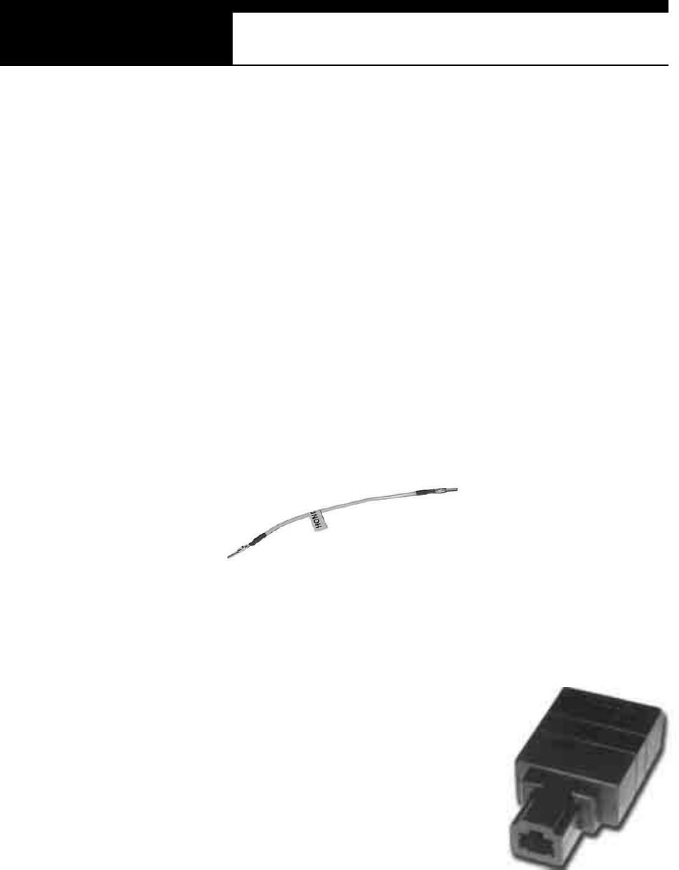
USER MANUAL For Multiscan
G
j G]G TGY[G
C. Adapters
1. 2-Pin Connector
a 2-pin adapter is generally found together with the 3-pin adapter, however,
some old cars may have this adapter only.
b Live data (Data stream ) is not available for all systems when using this
2-pin adapter. Only reading the flash signal in the dash panel is available
with this adapter and bi-directional serial communication with a scanner
is not available. Therefore, it supports the Trouble Code read function
only.
2. 3 Pin connecto r
a 3-pin adapter is generally found together with
the 2 -pi n ada pte r, how eve r, som e ca rs m a y
have this adapter only.
b Live data is available but some ABS and SRS
systems may support Trouble Code pulse
signal onl y.
3. 2 + 3 Pin connector
a 2-pin and 3-pin adapters are generally found together. In this case,
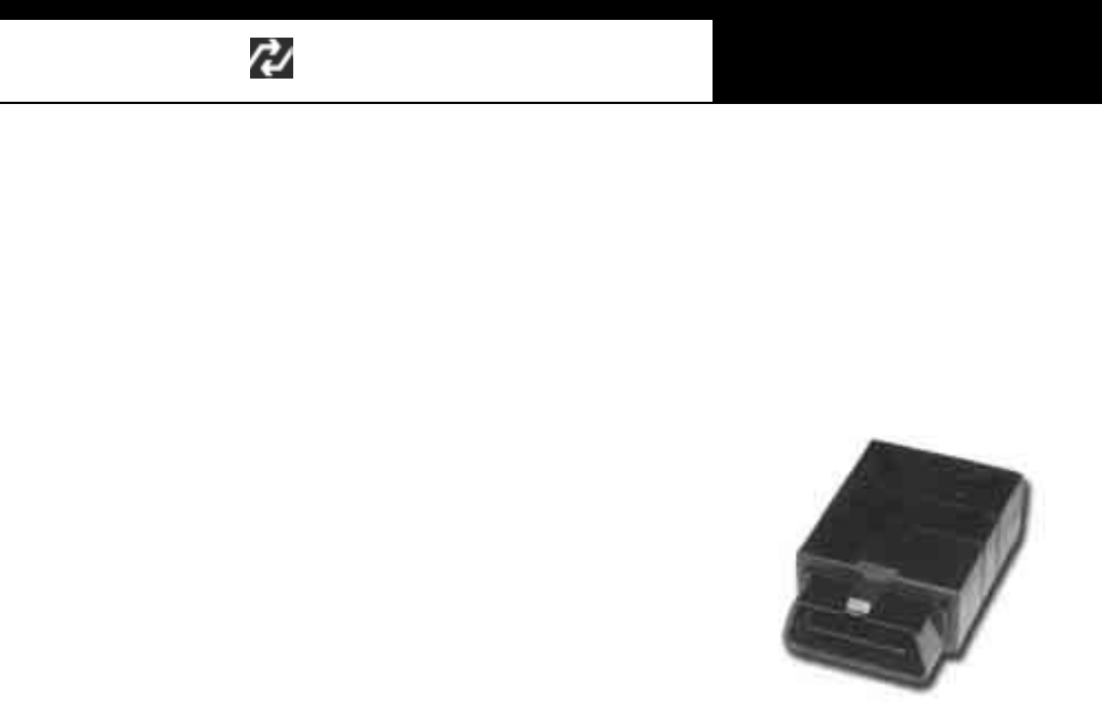
HANA TECH CO., LTD. Chapter 6
G
j G]G TGY\G
each adapter is assigned to different systems in the car.
b You are recomm ended to try to tes t the s ys tem wi th 3-pin adapter f irs t,
and then try with 2-pin adapter in the event communication using 3-pin
adapter fails.
4. 16 Pin connecto r
16-pin adapter equates to the OBD2 s tandard
adapter. Fault Code read and erase, and live
data is supported for all systems.
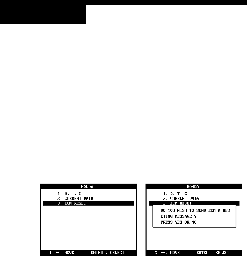
USER MANUAL For Multiscan
G
j G]G TGY]G
D. ECM RESET function
-Foll owing ECM repl acem ent, faul t code erasi ng or when you feel the
necessity to reset ECM adaptation due to poor engine perform ance, you can
activate this function.
-It cleans up the ECM memory and makes the ECM ready for self-adaptation.
1. Select ECM RES ET
You may select this function when you select the ENGINE CONTROL
system from the SELECT DEVICE menu that follows the adapter type
selection.
2. A fter Reset
After the resetting, ECM needs some time to relearn the idling condition
and finalize self-adaptation.
Start and idle the car for more than 5 minutes after warm -up.
Otherwise poor engine performance will result.G
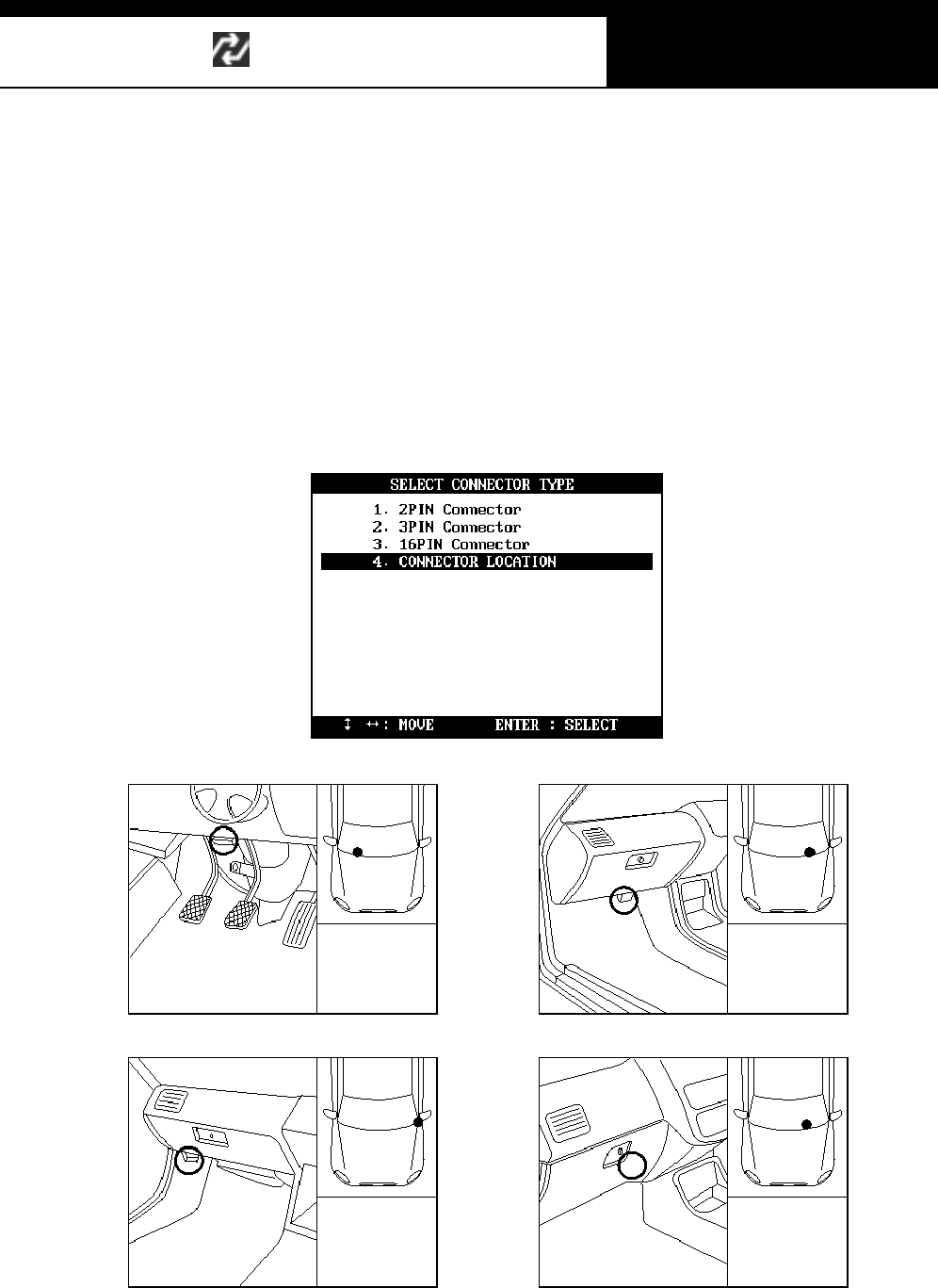
HANA TECH CO., LTD. Chapter 6
G
j G]G TGY^G
G
E. Adapter location
a The location drawings are purely from the experience of Hanatech and
provided for your reference only.
b The drawings are based on Right Hand Drive cars, therefore, you may
have to consider the mirror image for any Left Hand Drive cars.
c You can view these drawings on the Multiscan screen by selecting
[3.Connector Location] after s electi ng [3. HOND A] from the car make list.
USER MANUAL For Multiscan
G
j G]G TGY_G
F. Vehicle Coverage
-The vehicle coverage listed below is limited to the cars that supports live
data (Data stream / Service data) with 3-pin or 16-pin adapter
-Older cars with 2-pin adapter are not included.
JAPAN ESE DOMESTIC
Model Name From Until
Accord 1994 2002
Acty 1994 2002
As cot 1994 1997
Avancier 2000 2002
Capa 1998 2001
Civic 1992 2002
Civic Coupe 1993 1996
Civic 5Door 2001 2002
Civic Hybrid 2002 2002
Stream 2001 2002
CR-V 1996 2002
CR-X 1992 1996
Domani 1993 2000
Fit 2002 2002
HR-V 1999 2002
Insight 2000 2002
Inspire 1995 2000
Ins pire V6 1995 2003
Integra 1992 2002
Integra SJ 1996 2000
Lagreat 1999 2002
Legend 1996 2002
Life 1997 2002
Logo 1997 2001
Mobilio 2002 2002
NSX 1995 2002
Odyssey 1995 2002
Odyssey V6 1998 2002
Orthia 1996 2000
Partner 1996 2000
Prelude 1992 2001
Rafaga 1994 1997
S2000 1999 2002
Saber 1995 2003
S-MX 1997 2001
Step Wagon 1996 2002
That's 2002 2002
Today 1993 1998
Toreno 1998 2002
Vamos 1999 2002
Z 1999 2000
HANA TECH CO., LTD. Chapter 6
G
j G]G TGY`G
NORTH AMERICAN
Model Name From Until
Accord 1994 2002
Accord V6 1995 2002
Acura 1.6EL 1997 2000
Acura 1.7EL 2001 2002
Acura 2.2CL 1997 1997
Acura 2.3CL 1998 1999
Acura2.5TL 1995 1998
Acura 3.0CL 1997 2000
Acura 3.2CL 2001 2003
Acura 3.2TL 1995 2003
Acura 3.5RL 1996 2002
Acura MD-X 2001 2002
Acura RSX 2002 2002
Civic 1992 2002
Civic Coupe 1993 2002
Civic Hybrid 2002 2003
CR-V 1997 2002
CR-X 1992 1997
Insight 2000 2002
Integra 1992 2001
NSX 1995 2002
O dyss ey 1995 2002
Pil ot 2003 2003
Prelude 1992 2001
S2000 2000 2002
EUROPEAN
Accord 1994 2002
Accord V6 1998 2002
Civic 1992 2002
Civic Aero 1998 2000
Civic Coupe 1994 2002
Civic 5Door 1995 2001
Stream 2001 2002
CR-V 1997 2002
CR-X 1992 1997
HR-V 1999 2002
Insight 2000 2002
Integra 1998 2002
Jazz 2002 2002
Legend 1996 2002
Logo 1999 2000
NSX 1995 2002
Prelude 1992 2001
S2000 2000 2002
Shuttle 1995 1999
USER MANUAL For Multiscan
G
j G]G TGZWG
GENER AL
Accord 1994 2002
Accord V6 1995 2002
Acura 2.5TL 1995 1998
Acura 3.2TL 1996 2002
Acura 3.5TL 1996 2002
Ci ty 1996 2001
Civic 1992 2002
Civic Coupe 1994 2002
Civic 5Door 1997 2002
Stream 2001 2002
CR-V 1996 2002
CR-X 1992 1997
FIT 2002 2002
HR-V 1999 2002
Insight 2001 2002
Ins pire V6 1999 2000
Integra 1992 2002
Jazz 2002 2002
Legend 1996 2002
Logo 1999 2000
NSX 1995 2002
O dyss ey 1995 2002
O dyss ey V6 2000 2002
Pil ot 2003 2003
Prelude 1992 2001
S2000 2000 2002
Step Wagon 1998 2003
Vigor 1995 1998
HANA TECH CO., LTD. Chapter 6
G
j G]G TGZXG
III. NISSAN ----------------------------------------
A. Features of Nissan S/W
1. Communicatio n Start-up
a Nissan has neither the ECM ID check system like Honda nor the
compli cated menu selection system like Toyota.
b After system selection, the scanner sends a set of commands to the
ECM for all data listings available within the vehicle, and then
com municates with the ECM for the avail able items only.
USER MANUAL For Multiscan
G
j G]G TGZYG
c The system check commands and communication details have been
constant without change for both 14-pin and 16-pin diagnostic adapters.
Therefore, a scanner does not need to know the ID number or the
detailed vehicle specification. Simply select the adapter type and the
s canner will comm uni cate with the ECM for all avail able items.
2. Performance
a Mul tis can NI SSAN s oftware is appli cable to all Niss an cars up to 2002
model year as of May 2003.
b System Coverage
Engine, Transmission, ABS, SRS,
IVMS (In Vehicle Multiple System): Body control
HICAS (High Intelligence Control Active Steering)
AS CD (Automatic Speed Control Device): Cruise control.
3. Menu Se lection
a Select NISSAN
Select NISSAN / INFINITI from the car make menu.
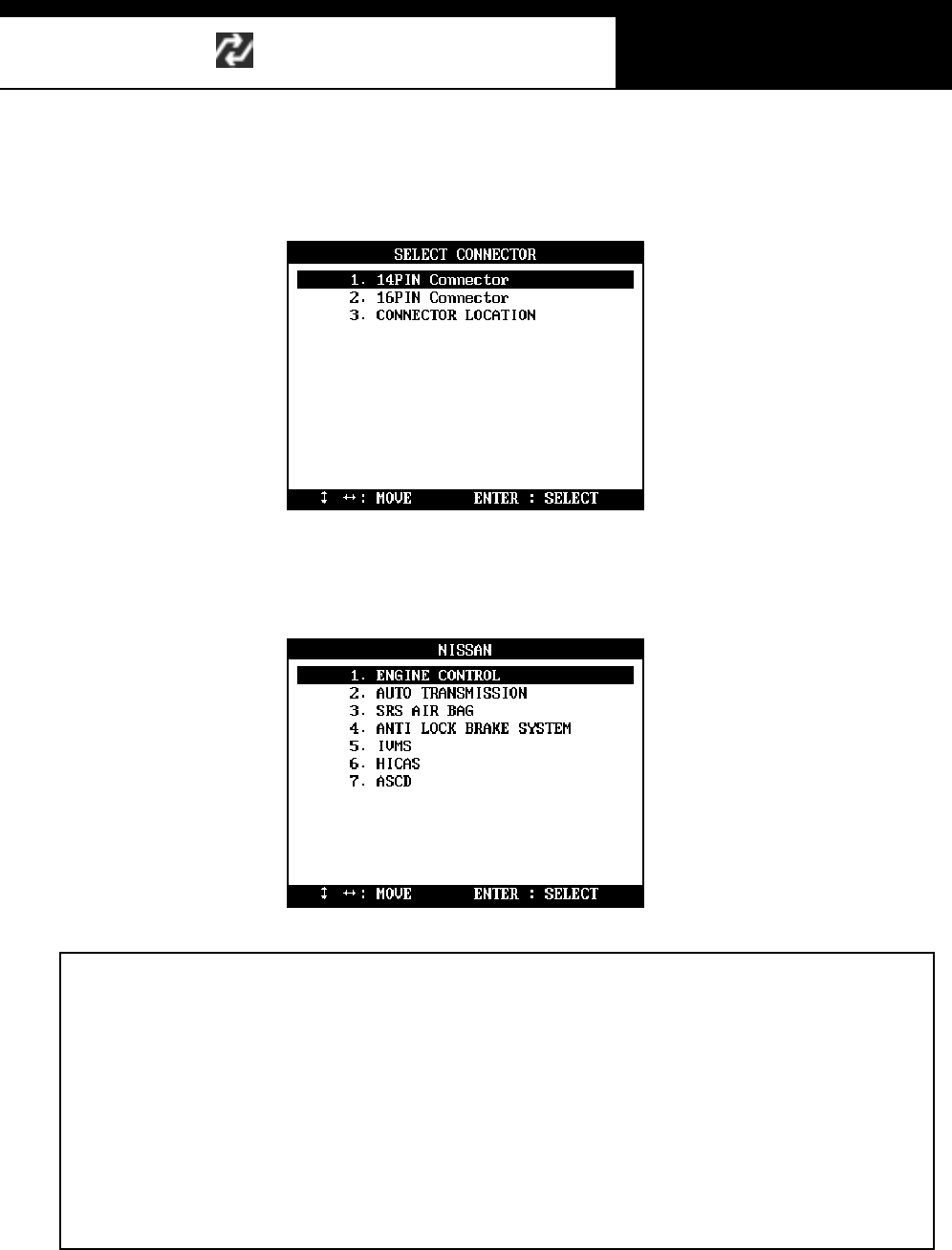
HANA TECH CO., LTD. Chapter 6
G
j G]G TGZZG
b Select the adapter type
Find the diagnostic connector in the car referring to the connector location
drawings hereinafter and select the connector type found.
c Select test system
Select the system you want to test
Mul tis can alw ays shows 7 s ys tems for sel ection i n the m enu. However, it doesn’ t m ean
that the car has all the systems and that all of the systems are available for
communication with Multiscan.
Select any control module from the menu as illustrated above, then Multiscan will try to
talk to the selected control module. If the control module responses properly, then
Multiscan shows the detailed function listings for the control module.
If it shows the “Communication Error” message, it is considered the vehicle has no
such a system or the control module does not support scanner communication.
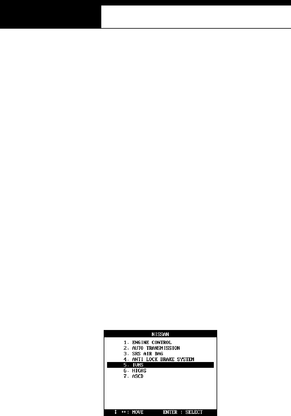
USER MANUAL For Multiscan
G
j G]G TGZ[G
B. Adapters
a 14-pin and 16-pin adapters are being used for Nissan cars.
In North America, Nissan cars of 1995 model year or later usually have
16-pin OBD2 adapter while the older cars have 14-pin adapter. Some
cars released around 1996 may have both connectors.
b Outside North America, late models of Nissan continue to use the 14-pin
adapter in some countries, therefore, the application of each adapter is
yet to be confirmed.
Refer to the connector location hereinafter, and search for the adapter
first to make a correct selection.
C. IV MS (als o appli cabl e to HICAS and ASC D s ystems)
1. System Me nu
a Mul tis can always s hows the IVMS in the s ystem s election m enu.
However, it doesn’ t conclude that the car has the s ys tem or i t is availabl e
for comm uni cation with Mul tiscan.
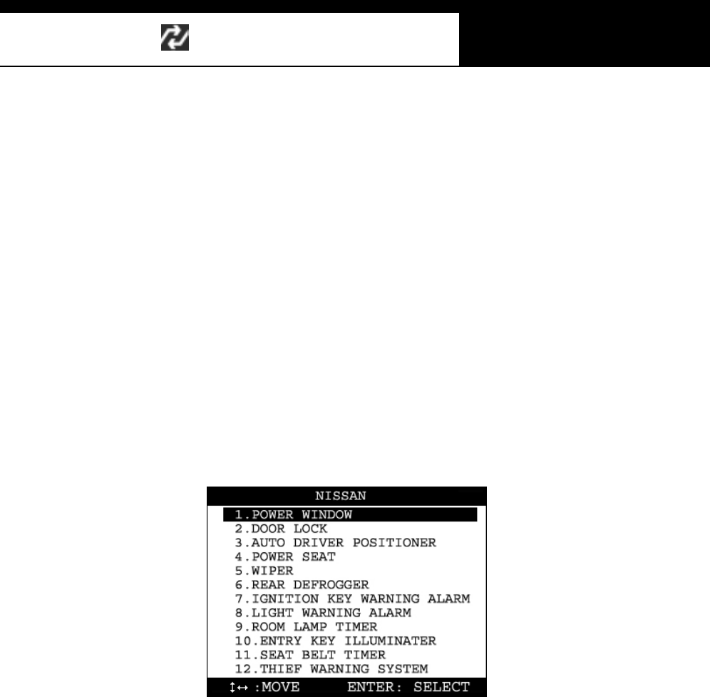
HANA TECH CO., LTD. Chapter 6
G
j G]G TGZ\G
b Select IVMS from the system menu as shown above, then Multiscan will
attempt communication to the IVMS control module. If the car has the
IVMS system, then Multiscan will show you the IVMS item listing.
c If the “Com municati on Error” mess age is displayed, the s ys tem is ei ther
not fitted to the vehicle or does not feature self-diagnos tics .
2. IVMS items
a Once the communication is established, Multiscan lists all 22 IVMS items,
however, in the same manner, it doesn’t mean that communication with
each of 22 items is supported by the IVMS m odule.
b Select an IVMS item from the IVMS menu, then Multiscan will
communicate to the IVMS control module to check if the item is
supported. If the item is supported, then Multiscan will show the
available functions with the item, in example, live data and actuation test.
c If the “Communicati on Error” mess age is displayed, it is probable that
the item is not supported by the IVMS module.
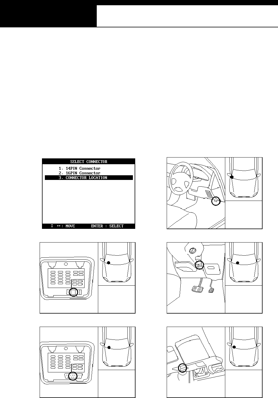
USER MANUAL For Multiscan
G
j G]G TGZ]G
D. Adapter location
-The location drawings are purely from the experience of Hanatech and
provided for your reference only.
The drawings are based on Right Hand Drive cars, therefore, you may
have to consider the mirror image for any Left Hand Drive cars.
-You can view these drawings on the Multis can s creen by s electi ng
[3.Connector Location] after selecting [4. NISAN] from the car make list.

HANA TECH CO., LTD. Chapter 6
G
j G]G TGZ^G
E. Vehicle Coverage
-Since the communication protocol for Nissan cars is quite stable with few
vari ations , vehi cl e coverage is meaningless to lis t in detail as for Toyota or
Honda.
-The followings are the examples of Nissan models that Hanatech or its
worldwide partners have tested and confirmed its successful communication
200SX, 240SX, 300ZX, ALTIMA, AXXESS, FAIRLADY, FRONTIER,
MAXIMA, MIN I VAN , N X, PATH FIND ER, PICKU P, PULSAR N X, QUEST,
SEN TRA, SKYLINE, STANZA, XTERRA, CEFIRO, SILVIA, TINO, 240SE,
MAR C H, VERI TA, AL MER A, PR I MER A, TERR AN O II , PATR OL GR, etc.
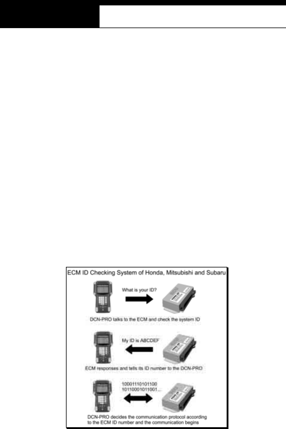
USER MANUAL For Multiscan
G
j G]G TGZ_G
IV. MITSUBISHI ----------------------------------
A. Fea tures o f Mits ubis hi S /W
1. Communicatio n Start-up
a Mi ts ubishi has the ECM ID check s ys tem sim ilar to Honda.
Complicated menu selecting procedure as for Toyota is not necessary
for Mitsubishi cars.
b The user is simply required to check the adapter type of the vehicle and
to select the adapter and the desired system to test. Then Multiscan
automatically begins to talk to the ECM to identify the ID number and
determines its communication details according to the response.
c One thing different from Nissan is that the communication speed varies a
lot, therefore, Multiscan checks the speed of the incoming signal from an
ECM and determines communication speed automatically thereupon.
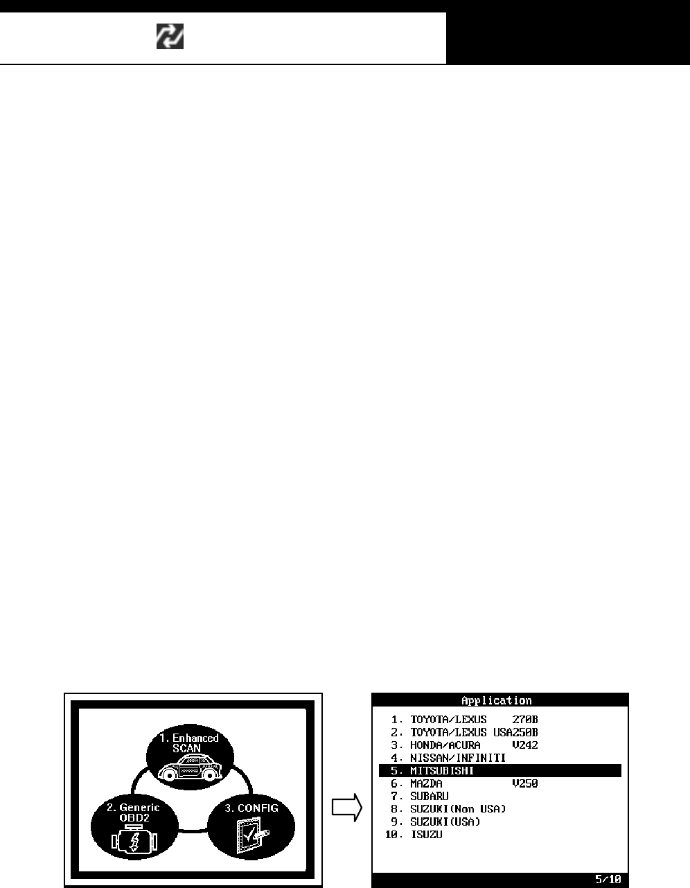
HANA TECH CO., LTD. Chapter 6
G
j G]G TGZ`G
2. Performance
a Mi ts ubishi original equipment has vari ous regional versions that cover
the Mitsubis hi cars in each regional m arket.
b Mul tis can Non-US A vers ion compris es of Japanese domes ti c, Aus tralian,
Mal aysian and European regional versions .
c Mitsubishi software covers up to 1,500 different system IDs when
counting the Engine control system only. Total 2,500 IDs are included
in the database for all Mitsubishi car systems.
d Multiscan Mitsubishi software provides original equipment level reliability
and accuracy for Mitsubishi cars up to 2002 model year.
B. Ge tting Started
1. Select Mitsub ishi
Select MITSSUB ISHI from the car m ake menu.
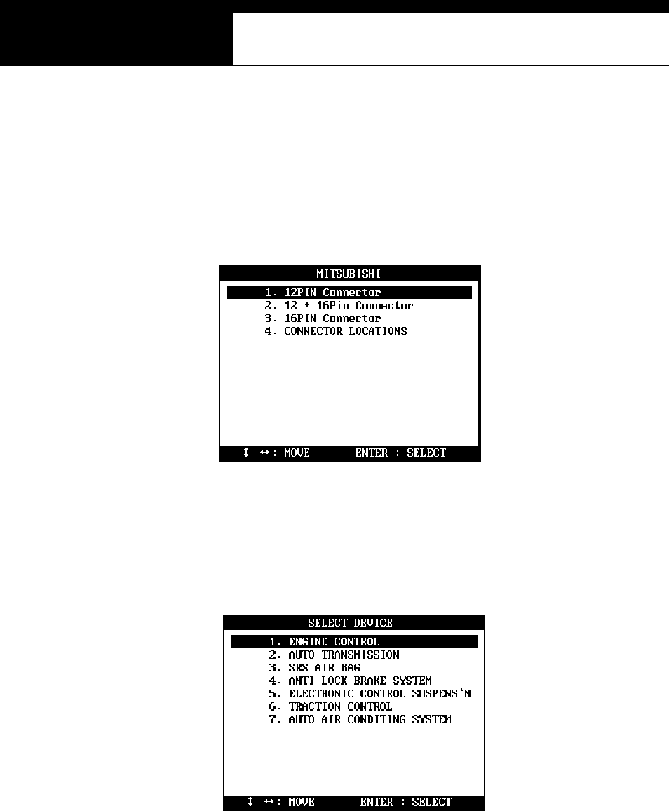
USER MANUAL For Multiscan
G
j G]G TG[WG
2. Select the adapter type
Search for the diagnostic connector in the car referring to the connector
location drawings hereinafter and s elect the connector type you found.
3. Select test system
Select the system you want to test
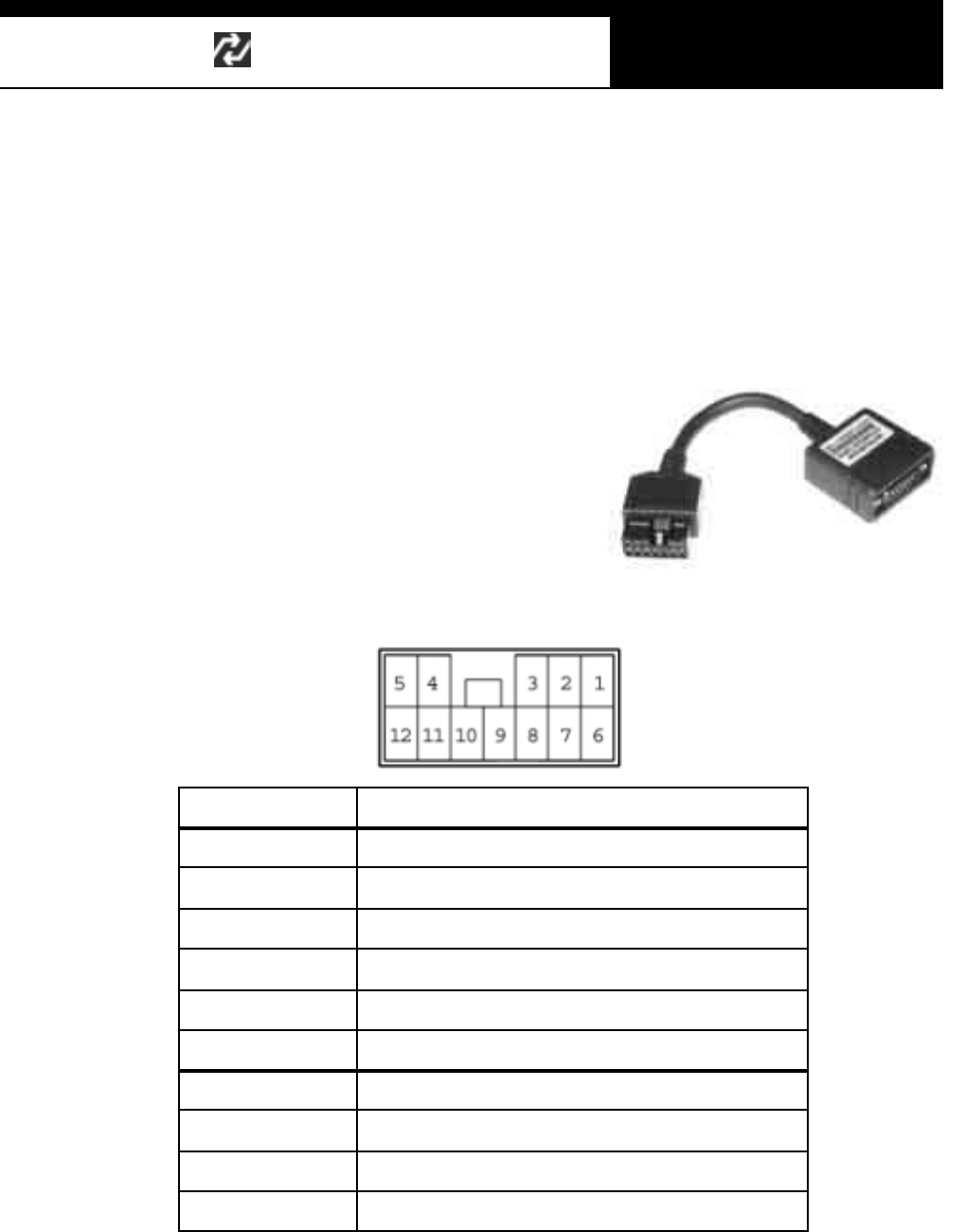
HANA TECH CO., LTD. Chapter 6
G
j G]G TG[XG
C. Adapters
1. 12-Pin Connector
a 12-pin adapter is widely used for all Mitsubishi cars of OBD generation 1.
b It provides the same level of data
readings as the OBD2 adapter. Read
/ Erase of fault codes, actuation test
and data stream are available for all
systems except ETACS.
c This adapter is also used for Korean
Hyundai and Malaysian Proton cars.
Pin number Assigned System
1 Engine – MPI
2 Steering - 4WS
3 Sus pension - Acti ve ECS
4 Brake – ABS
5 Cruise Control – ASC
6 Transmissi on - ELC-4AT
7 Air Conditioner - Full Auto AC
8 Air Ba g – SRS
9 ETACS: Pulse signal onl y
12 Ground
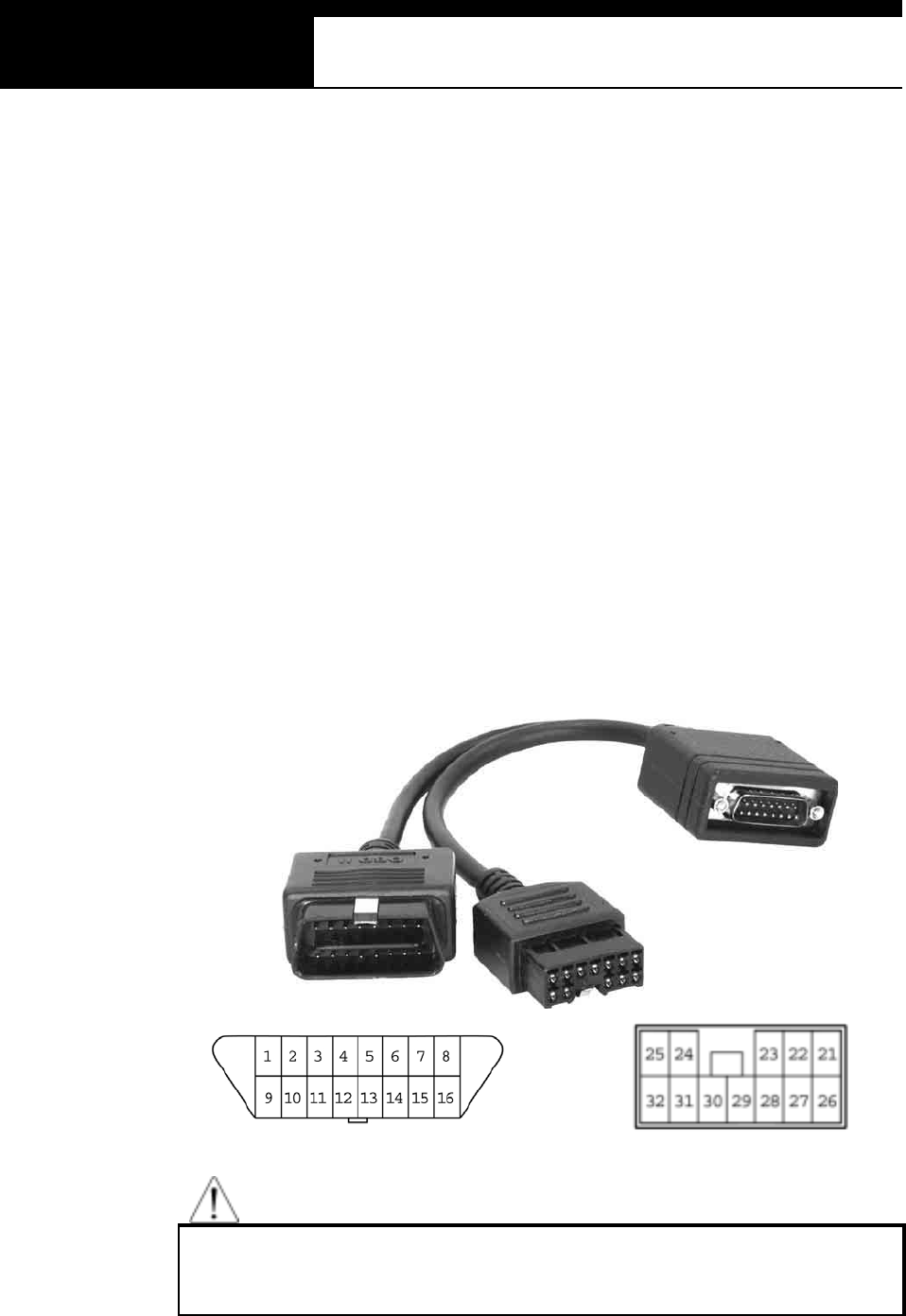
USER MANUAL For Multiscan
G
j G]G TG[YG
2. 12+16 Pin Connectors
a Many of Mitsubishi cars manufactured in mid 90`s have both the 12-pin
Mitsubishi adapter and OBD2 16-pin adapter.
b Many Mitsubishi control modules with MELCO system communicate
using its own conventional protocol, which is not OBD2 compliant even
though t he vehi cle has the O BD 2 standard adapter.
c With MELCO s yst em, each pin of the OBD 2 adapter is ass igned to
individual control module, therefore, when the total number of control
module exceeds the number of pins, it is necessary to use additional
ad apt e r to co ve r t h e e xce ssive co ntrol mo dules .
d When the vehicle has both the OBD2 16-pin and Mitsubishi 12-pin
adapters, the 12+16 pin dual headed adapter must be connected for
proper operation.
WARNING
Do not use this adapter when there is only one 16-Pin OBD2 adapter or
12-Pin Mitsubis hi adapter. Us e the corres ponding s ingle adapter.
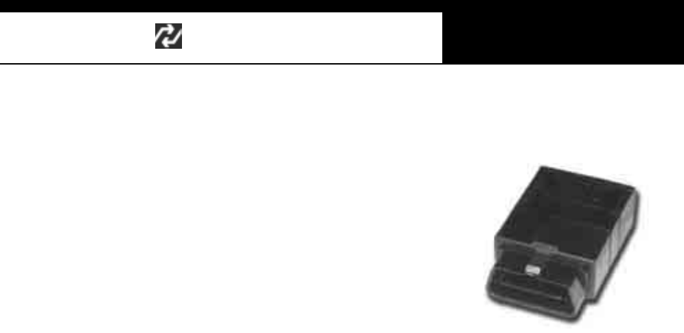
HANA TECH CO., LTD. Chapter 6
G
j G]G TG[ZG
3. 16 Pin connecto r
a 16-pin adapter equates to the OBD2
standard adapter. Live data is supported
for all systems except ETACS and some
early transmissions
b All systems in the control system selection
menu are covered with this adapter when it is found alone in the vehicle.
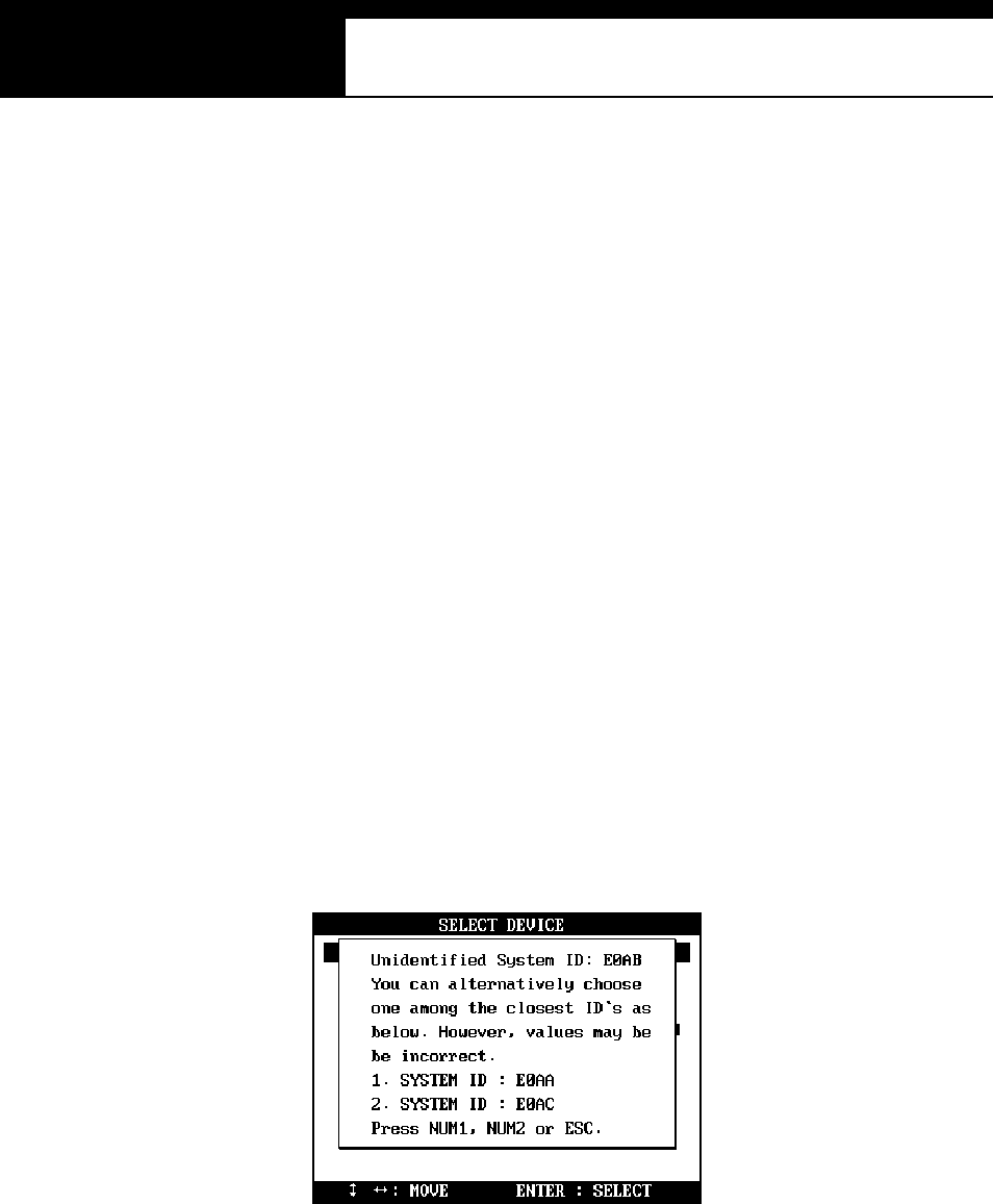
USER MANUAL For Multiscan
G
j G]G TG[[G
D. Unidentified system ID
1. System ID Check
As explained herein, Multiscan automatically checks the system ID when you
select a control system and sets up the communication with the control
module thereupon. Multiscan Mitsubishi software contains thousands of
system ID for various regional market specifications, however, it is still
possible that you may encounter Mitsubishi cars of which system ID is not
included in the Mul tis can softw are databas e.
2. Alternative System IDs
When Multiscan finds an unknown system ID or when it cannot find the
matching system ID in the database, it shows the closest system IDs for you
to alternatively s elect as shown below :
In the example, Multiscan found that the actual system ID E123 is not
i ncl uded in the database, and it presents tw o clos est IDs of E122 and
E124 for the user’s alternative selection.

HANA TECH CO., LTD. Chapter 6
G
j G]G TG[\G
3. Possible inco rrect values
This is bas ed on the concept that t he closest s ystem IDs s hare the
majority of system characteristics with the least differences. However,
we cannot guarantee the accuracy of data values when choosing an
alternative ID.
4. Cooperation for Update
Should you encounter any of these missing IDs, please contact your local
distributor with the ID numbers so that we can add them in the next
software update.
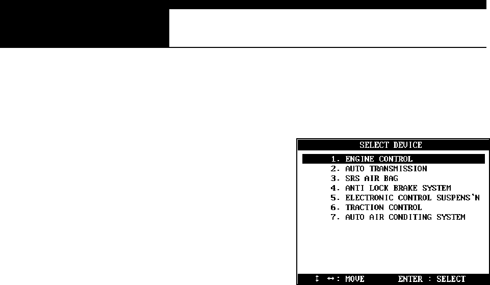
USER MANUAL For Multiscan
G
j G]G TG[]G
E. Communication Error
1. Menu
Mul tis can always s hows 7 control
s ys tem s in the menu as shown in the
il lus tration, however, it does n’t m ean
that the test vehicle has all the lis ted
systems available for scanner
communication.
2. Checking the existence of selected contro l systems
To confirm that the selected is equipped with the electronic control module for
the system you want to test, observing the warning lamp soon after turning
the ignition key ON. Then let Multiscan talk to the control module first by
selecting a system after connecting the correct adapter.
3. Success and Failure
Successful communication or Unidentified ID report confirms that the system
is available for scanner communication.
To the contrary, in the case of communication failure, please check the
following:
z The vehicle does not have an electronic control module for the
selected system
z If the vehicle has the electronic control system:
9 Im proper adapter selection or poor contact
9 Control module or communication wiring is defective
9 Unable to establish communication with the control module due
t o i n comp le te Multis can s of twa re (C on t act you r local dis trib utor)
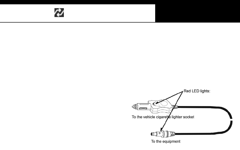
HANA TECH CO., LTD. Chapter 6
G
j G]G TG[^G
F. Power supply
1. 12-pin adapter
Mi ts ubishi 12-pi n adapter has no
pin for power supply. You have
to use the cigarette lighter power
cabl e to s upply power t o
Multiscan head unit when you
are using this adapter for
communication.
2. OBD2 adapter
The OBD 2 adapter does not require external power s uppl y as 12V battery
power is supplied from the adapter.
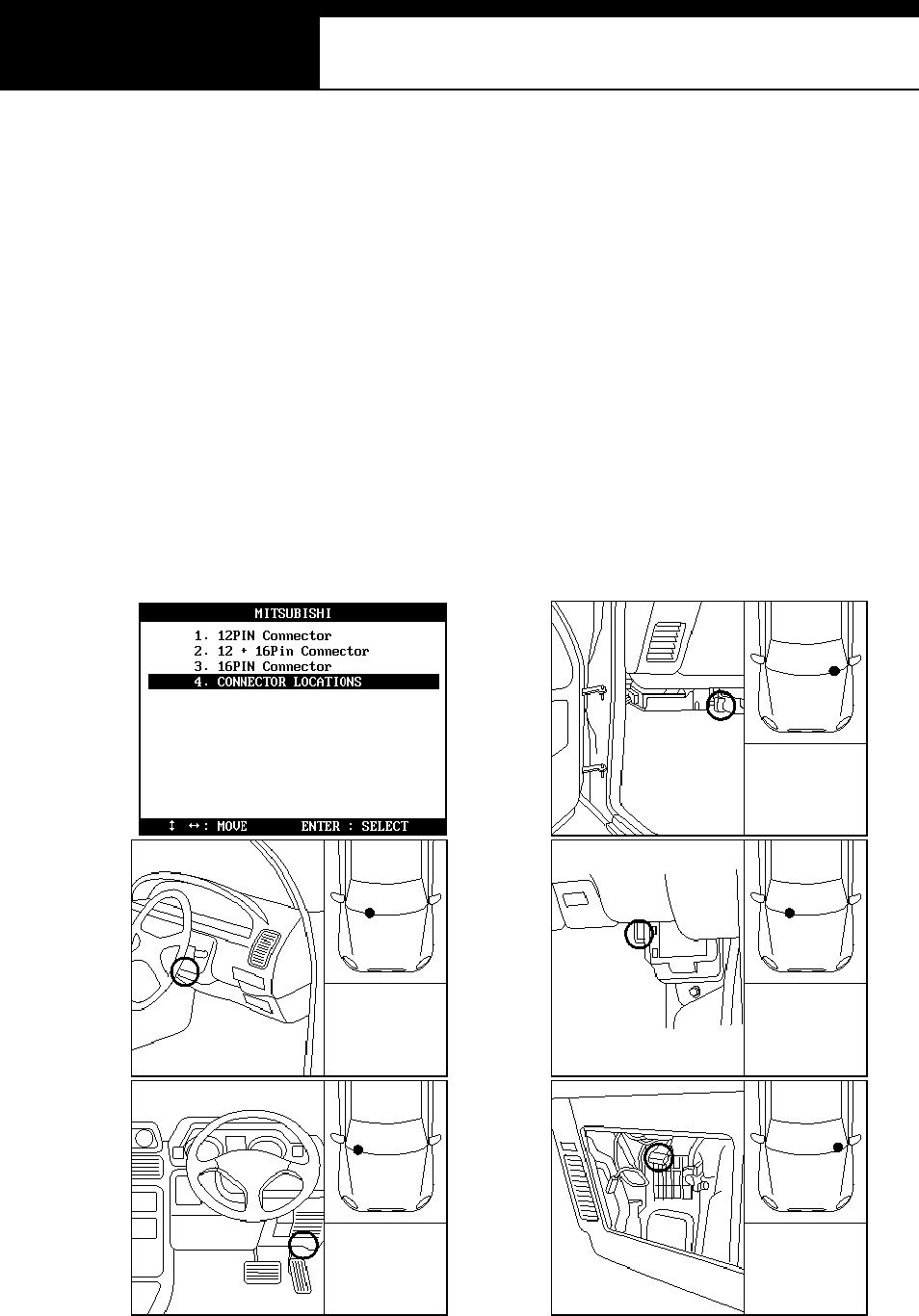
USER MANUAL For Multiscan
G
j G]G TG[_G
G. Adapter location
z The location drawings are purely from the experience of Hanatech and
provided for your reference only.
z The drawings are based on Right Hand Drive cars, therefore, you may have
to consider the mirror image for any Left Hand Drive cars.
z You can view thes e drawings on the Mul tis can s creen by s electi ng
[4.Connector Location] after s electi ng [MITSUBISHI] from the car m ake l ist.

HANA TECH CO., LTD. Chapter 6
G
j G]G TG[`G
H. Vehicle Coverage
z The communication protocol for Mitsubishi cars is quite stable with few
variations. Since the communication between a scanner and control module
is established not by the model name but by the system ID, knowing the exact
system ID is the most important and the vehicle coverage in the list of model
nam es as Toyota or Honda is almost meani ngless .
z The following are the examples of Mitsubishi model names that Hanatech and
its worldwide partners have tested and confirmed its successful communication
3000 GT, Carisma, Diamante, Eclipse, Expo, Galant, Lancer, L200, Mirage,
Legnum, Libero, Montero, Pajero, Shogun, Space W agon, etc.
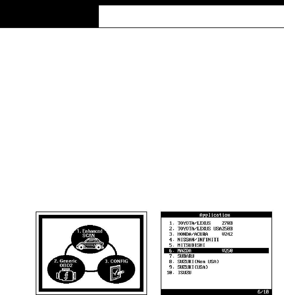
USER MANUAL For Multiscan
G
j G]G TG\WG
V. MAZDA ----------------------------------------
A. Features of Mazda S/W
1. Communicatio n Start-up
a Mazda has no ID check system like Honda or Mitsubishi.
Since the communication protocol is quite simple with few variations,
complicated menu selecting procedure as Toyota is not necessary, either.
b The user is simply required to check the adapter type of the vehicle and
to select the adapter and the desired system to test.
2. Performance
a Mazda has three different communication methods: Pulse signal type for
old cars, Mazda MOBD and Generic OBD2 of SAE J1850 type, and uses
three types of diagnostic adapter: 6-pin Mazda/Kia adapter, 17-pin
Mazda adapter and OBD2 16-pin adapter.
b Only the pulse signal type Diagnostic Trouble Code reading function is
HANA TECH CO., LTD. Chapter 6
G
j G]G TG\XG
available when using 6-pin or 17-pin manufacturer’s adapter.
Fault code erase and Data Stream are available only when the OBD2
16-pin adapter is used.
c Multiscan Mazda software is based on the vehicles built in Japan. It
may not be compatible with Mazda cars locally manufactured in other
countries.
B. Adapters
1. Mazda/Kia 6-pin adapter
Only the pulse signal type DTC reading
function for Engine control system is
available when using this type of
adapter.
2. Mazda 17-pin adapter
a Mul tis can s upports only t he Di agnos tic Trouble
Code reading function for Power train,
Transmission, Airbag, ABS, Cruis e Control and
Air conditioner control systems when using this
type of adapter
b The adapter looks the same as Toyota/Lexus Semi-circular adapter.
The Mazda adapter is colored light gray for distinction from Toyota. Be
careful not to apply the wrong adapter. This may cause malfunction of
either vehicle control module or Multiscan.
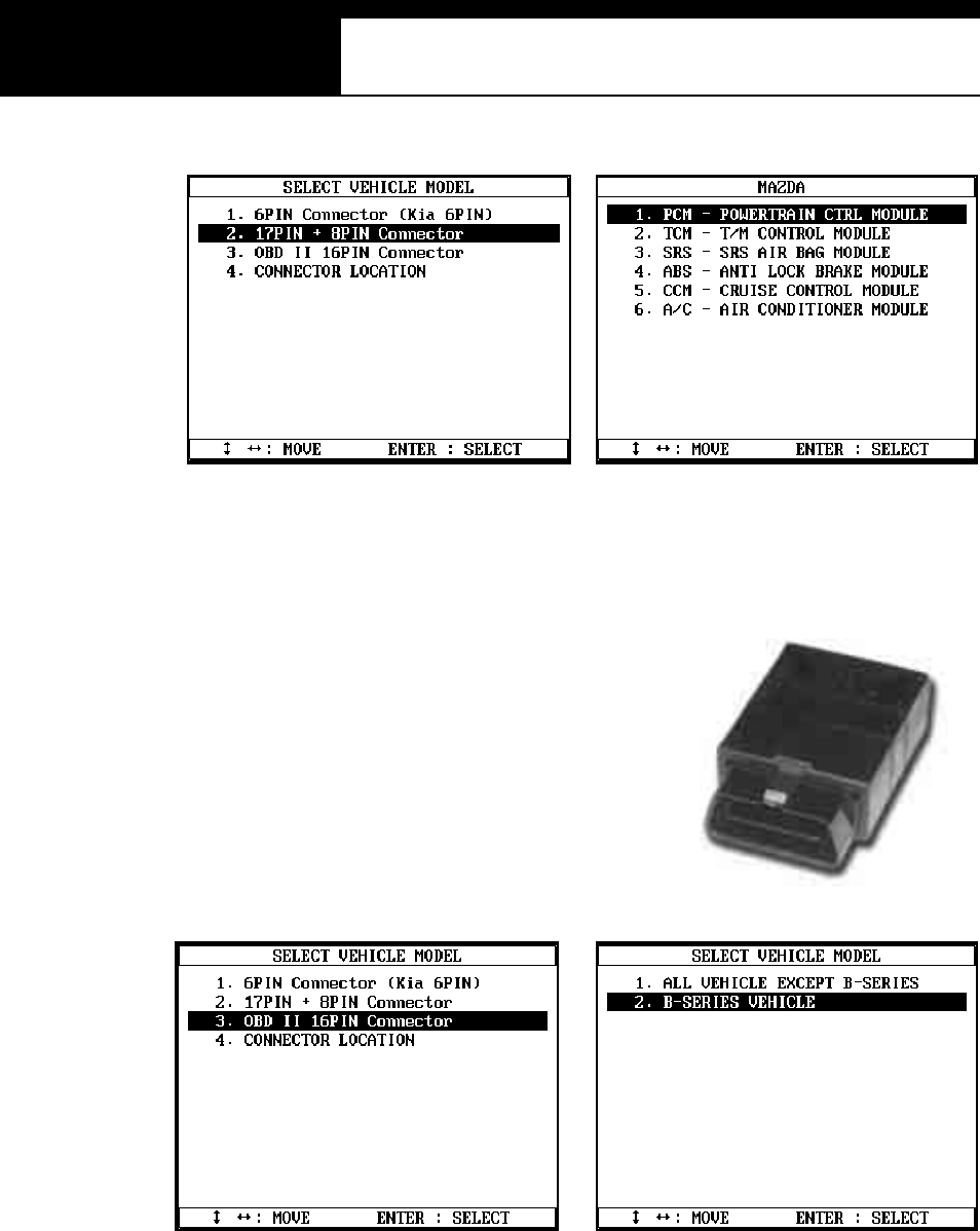
USER MANUAL For Multiscan
G
j G]G TG\YG
3. OBD2 16-pin adapter
1) DTC read / erase and Data stream
functions are available when using
OBD2 16-pin adapter.
2) You can make selection among “B
s eri es t rucks ” and other cars in the
next step menu when choosing this adapter.
3) Powertrain, ABS, Generic Electronic and Integrated Airbag modules
are available for the “B series” trucks. Only Powertrain and ABS
are available for other models.
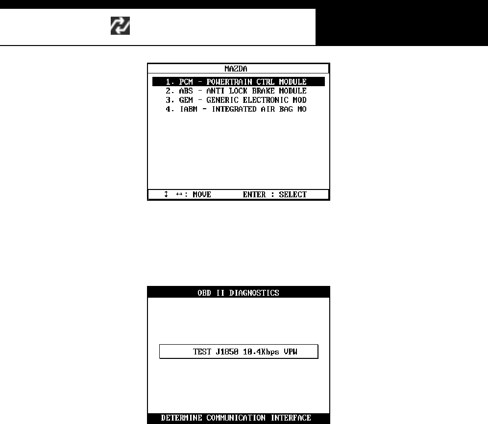
HANA TECH CO., LTD. Chapter 6
G
j G]G TG\ZG
4) Powertrai n m odul e comm uni cation is made by Generic OBD2
standard J1850 protocol, and the Mazda MOBD protocol is used for
all other systems.
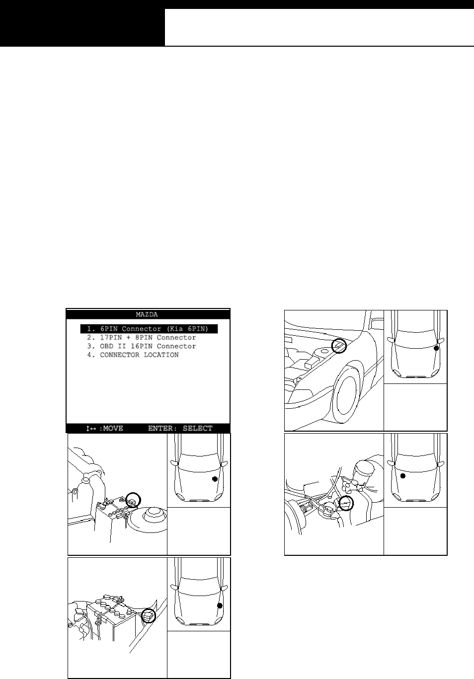
USER MANUAL For Multiscan
G
j G]G TG\[G
C. Adapter location
z The location drawings are purely from the experience of Hanatech and
provided for your reference only.
z The drawings are based on Right Hand Drive cars, therefore, you may have
to consider the mirror image for any Left Hand Drive cars.
z You can view thes e drawings on the Mul tis can s creen by s electi ng
[4.Connector Location] after s electi ng [MAZDA] from the car make lis t.

HANA TECH CO., LTD. Chapter 6
G
j G]G TG\\G
D. Vehicle Coverage
z The communication protocol for Mazda cars is very stable without variations.
Since the communication between a scanner and control module is established
automatically solely by selecting an adapter type without any specified vehicle
model selection or system ID check, detailed vehicle coverage like Toyota or
Honda is meaningless .
z The following are the examples of Mazda model names that Hanatech and its
worldwi de partners have tes ted and confirmed i ts success ful com munication.
323, 626, 929, MX3, MX6, Miata, Protégé, RX7, etc

USER MANUAL For DCN Scanners
G
j G]G TG\]G
VI. SUBARU ---------------------------------------
A. Features of SUBARU S/W
1. Communicatio n Start-up
a SUBARU has the ECM ID check system like Honda and Mitsubishi.
Complicated menu selection procedure as in Toyota is not necessary for
Subaru cars.
b The user is simply required to check the model year and then select the
system to test.
c Then Multiscan automatically begins to talk to the ECM to identify the
system ID and determines its communication details according to the
response from the ECM.

HANA TECH CO., LTD. Chapter 6
G
j G]G TG\^G
2. Performance
a Multiscan SUBARU software was engineered and developed in Australia
and New Zealand for the cars in this regional market where Multiscan
provides more than 90% of the original equipment coverage.
b Mu l tis can SU BAR U s oftwa re cove rs SU BARU ca rs from 19 94 model -
year up to 2002 as of May 2003.
c Subaru software is being upgraded and is scheduled to extend its
coverage to 1994 or earlier model years before the end of year 2003.
Please contact your local distributor and check the availability of update
3. Difference
a It is very diffi cult and tim e consuming to anal yze al l the s ystem IDs for a
certain car make. Most scanners provide only the limited readouts that
are commonly available in all SUBARU cars.
b Multiscan identifies each ECM version and provides the most optimized
and precise diagnostic inform ation of OE tool level.
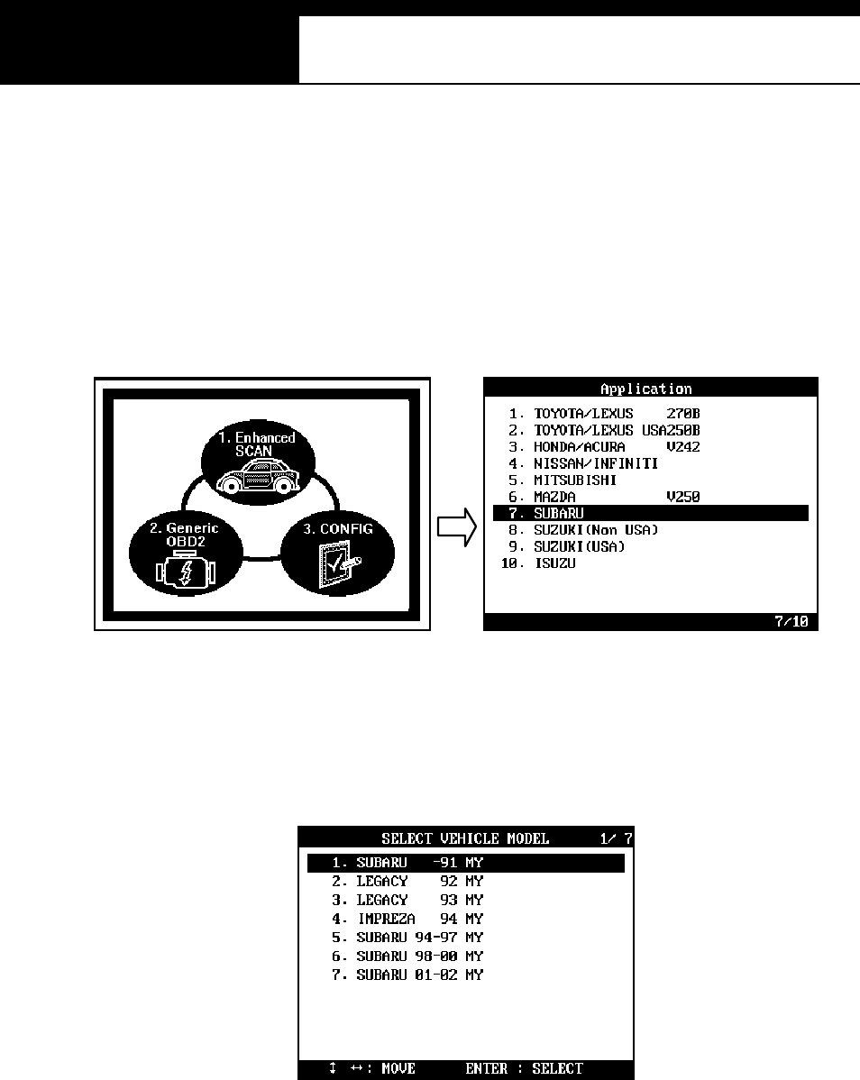
USER MANUAL For DCN Scanners
G
j G]G TG\_G
B. Menu Selection
1. Select SUBARU
Select SUBARU from the car make menu.
2. Select Model-year
Select the model year of the test vehicle.
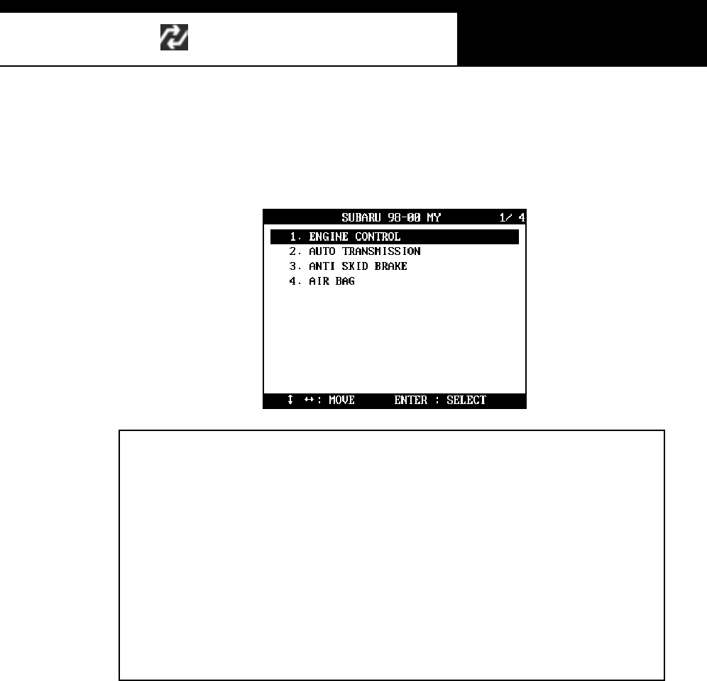
HANA TECH CO., LTD. Chapter 6
G
j G]G TG\`G
3. Select Test System
Select the system you want to test
zGGGG GGGGG
G
G GGGGSG G G
G
GGvikG G G G SG G G hi
z
G
UGGhGGGGGGGGG
SG G SG G SG G
S
G
G G G ¡ G G G G G UG
wGGGGGGGGGG
GUG
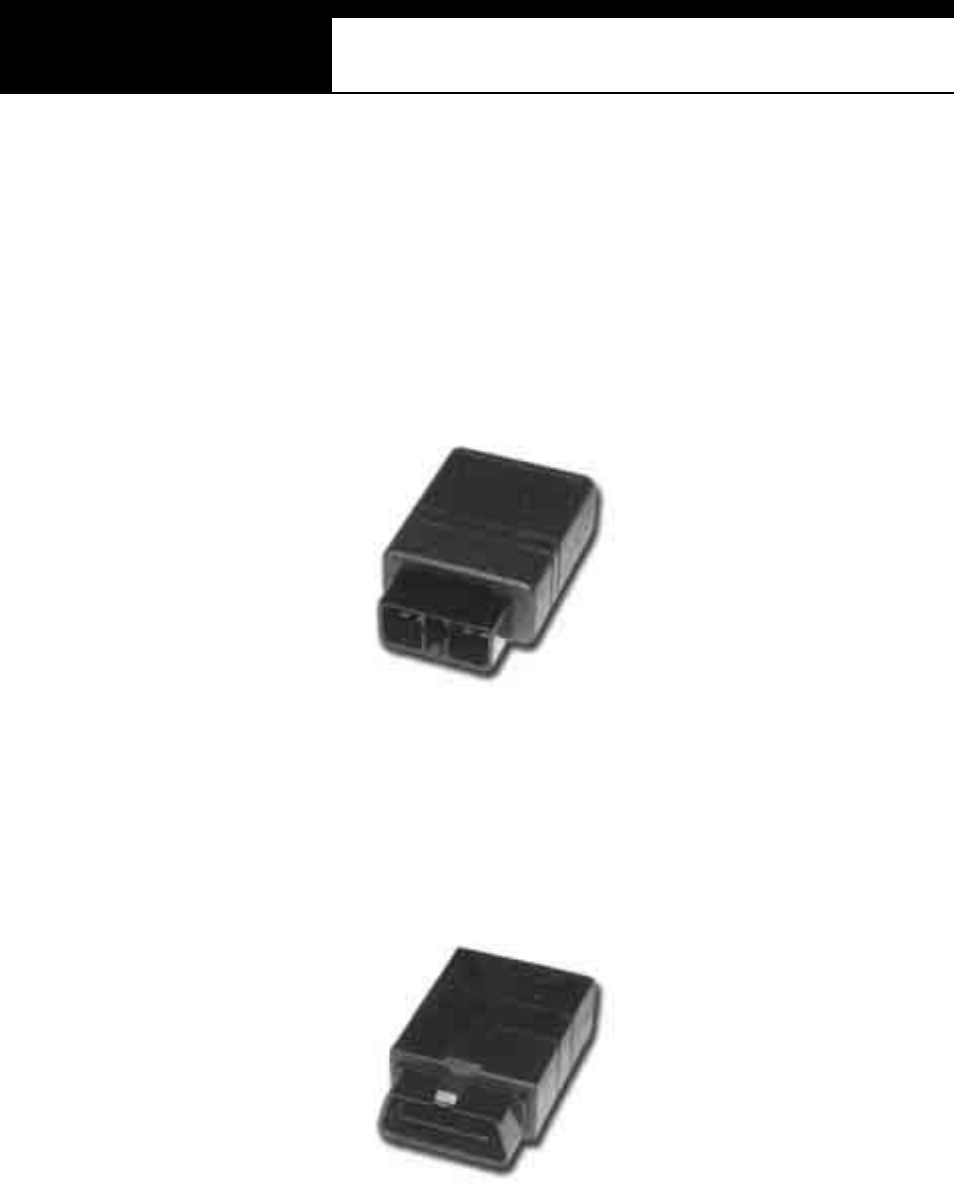
USER MANUAL For DCN Scanners
G
j G]G TG]WG
C. Adapters
1. 9 Pin Connector
SUBARU 9 pin adapter is widely used for most of SUBARU cars. Trouble
code read, erase and data stream are all available through this adapter.
2. 16-pin OBD2 connector
A standard adapter used for relatively new SUBARU cars. Trouble code
read and erase, and Data stream are supported.
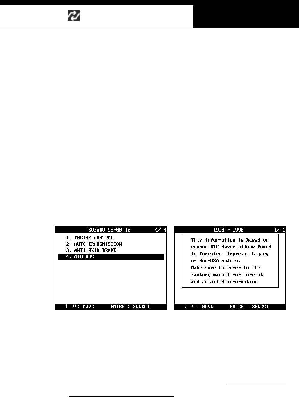
HANA TECH CO., LTD. Chapter 6
G
j G]G TG]XG
D. SRS airbag diagnosis
It is s aid t hat the manufacturer has designed the s ys tem without s canner
communication for safety reasons. You are recommended to check the trouble
codes m anuall y referring to the following inform ation. It is also recom mended
NOT to test SRS sys tem when using diagnostic equipment for t he other s ys tem s
s uch as Engine and Transm ission.
1. Selecting SRS
a When you select [4. Airbag] from the system selection menu, Multiscan
will show a message as shown below:
Please note that Airbag DTC descriptions that Multiscan provides on
screen are extracted from a few famous models of Subaru, roughly
identified by model years. However, the DTC definitions and
descriptions may differ according to the regional and vehicle detail
vari atio ns .
Therefore, Airbag DTC inform ation of Multiscan does not cover all
Subaru cars and may be incorrect.
It is always highly recommended to refer to factory m anuals for correct
and detailed information.
USER MANUAL For DCN Scanners
G
j G]G TG]YG
b Function sel ecti on menu follows when the [ENTER] key is pressed as
shown below:
2. Fault code list
When sel ected, Multis can shows the DTC des criptions of Subaru airbag
s ys tem as s h ow n b elo w. Yo u c a n r e fe r t o t hi s l is t aft e r rea di ng th e f a ul t
code(s) manually.
Once again, Airbag DTC information of Multiscan does not cover all Subaru
cars and may be incorrect.
It is always highly recommended to refer to factory manuals for correct and
detailed in formati on.
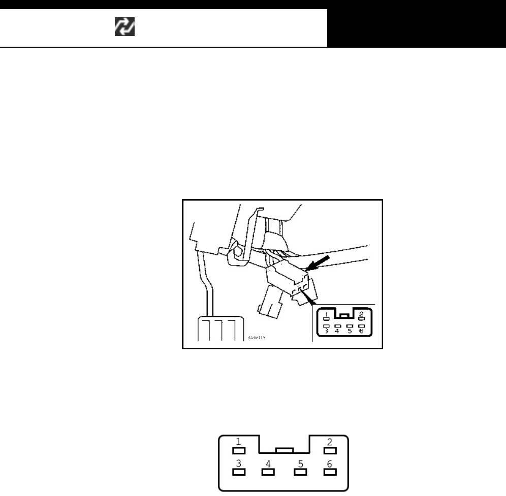
HANA TECH CO., LTD. Chapter 6
G
j G]G TG]ZG
3. Connector
a A separate connector is used for airbag system check.
When the [4. CONNECTOR] is selected, the illustration as shown below
follows.
b Locate the separate 6-pin harness for the SRS airbag under the dash
panel referring to the above illustration. The 6 pins of the connector are
numbered as shown below:
c Following charts are for SUBARU Forester 1997~98 and 99~00MY.
Refer to the original repair manual for the details of trouble codes of the
other models.
4. Fault Code Extraction
a Subaru SRS system does not support serial communication, therefore,
you have to read the fault code(s) from the 6-pin separate connector
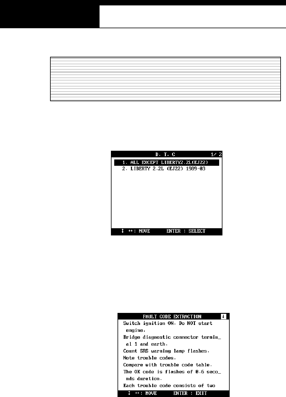
USER MANUAL For DCN Scanners
G
j G]G TG][G
manually observing the instructions displayed on Multiscan screen.
b There are two types of fault code extraction procedure, and you can
s elect am ong these two i n the menu that foll ows as below:
c ALL EXCEPT LIBERTY 2.2L (EJ22)
Select this item from the menu to extract fault code(s) from all Subaru
cars except Liberty 2.2L(EJ22). Following instruction will appear.
-Turn the ignition key ON without starting engine. Bridge
Instructions for manually reading DTC of Subaru airbag system are
from Hana Tech’s experiences only. It is recommended to refer to the
factory m anual to extract correct fault code(s).
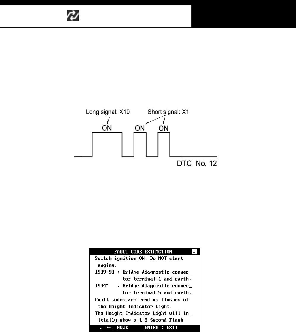
HANA TECH CO., LTD. Chapter 6
G
j G]G TG]\G
terminal 1 of the 6-pin connector and earth.
-The SRS warni ng lamp will begin t o f las h.
-Long flashes (1.2 sec) indicate the [Tens] of the DTC, and the
s hort ones (0.3 s ec) indicate the [ones (units )].
d LIBER TY 2.2L (EJ22)
Select this i tem from the menu to extract fault code(s ) from S ubaru
Liberty 2.2L(EJ22). Following instruction will appear.
-Turn the igniti on key ON without starting engine.
-For t he older cars f rom 1989 to 1993 model year, bridge the
connector terminal 1 and earth.
For the newer cars from 1994 model year, bridge the
connector terminal 5 and earth.
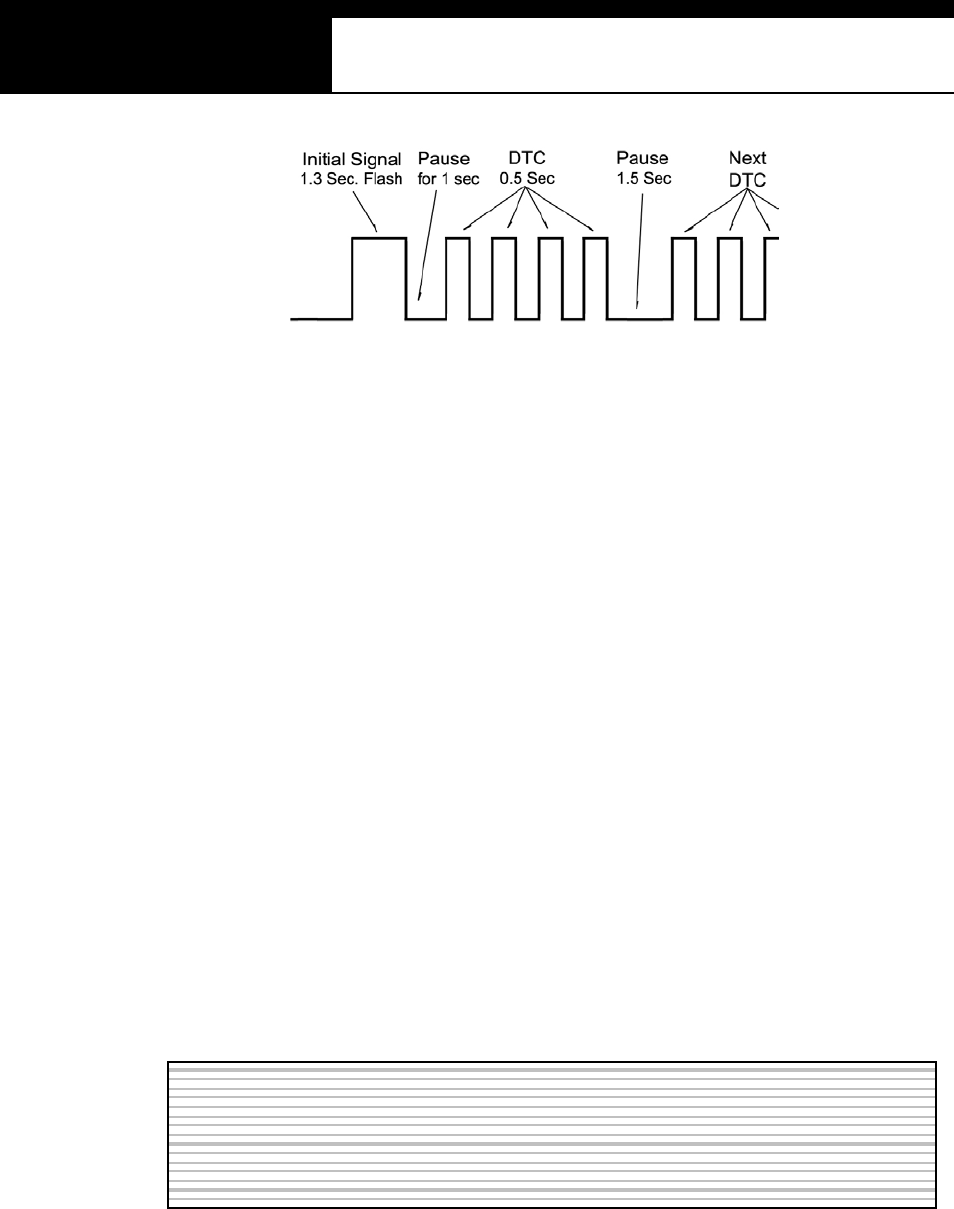
USER MANUAL For DCN Scanners
G
j G]G TG]]G
-The SRS warning lamp initially flashes for 1.3 second.
There is a pause for 1 second, followed by the codes of 0.5-
s econd flashes.
-When there are multiple codes, the next code follows after a
1.5-second pause.
-No Fault Code is represented by ON/OFF flashes on regular
intervals of 1.3 seconds .
5. Fault Code Erasure
a In the sam e manner as i n Fault Code Extraction, Subaru SRS s ys tem
does not support serial communication, therefore, you have to erase the
faul t code(s ) f rom the 6-pin s eparate connector m anuall y observi ng the
ins t ructions dis played on Mul tis can s creen.
b There are two types of fault code erasure procedure, and you can select
among these two in the menu that follows as below:
Instructions for manually reading DTC of Subaru airbag system are
from Hanatech’s experiences only. It is recommended to refer to the
factory m anual to extract correct fault code(s).
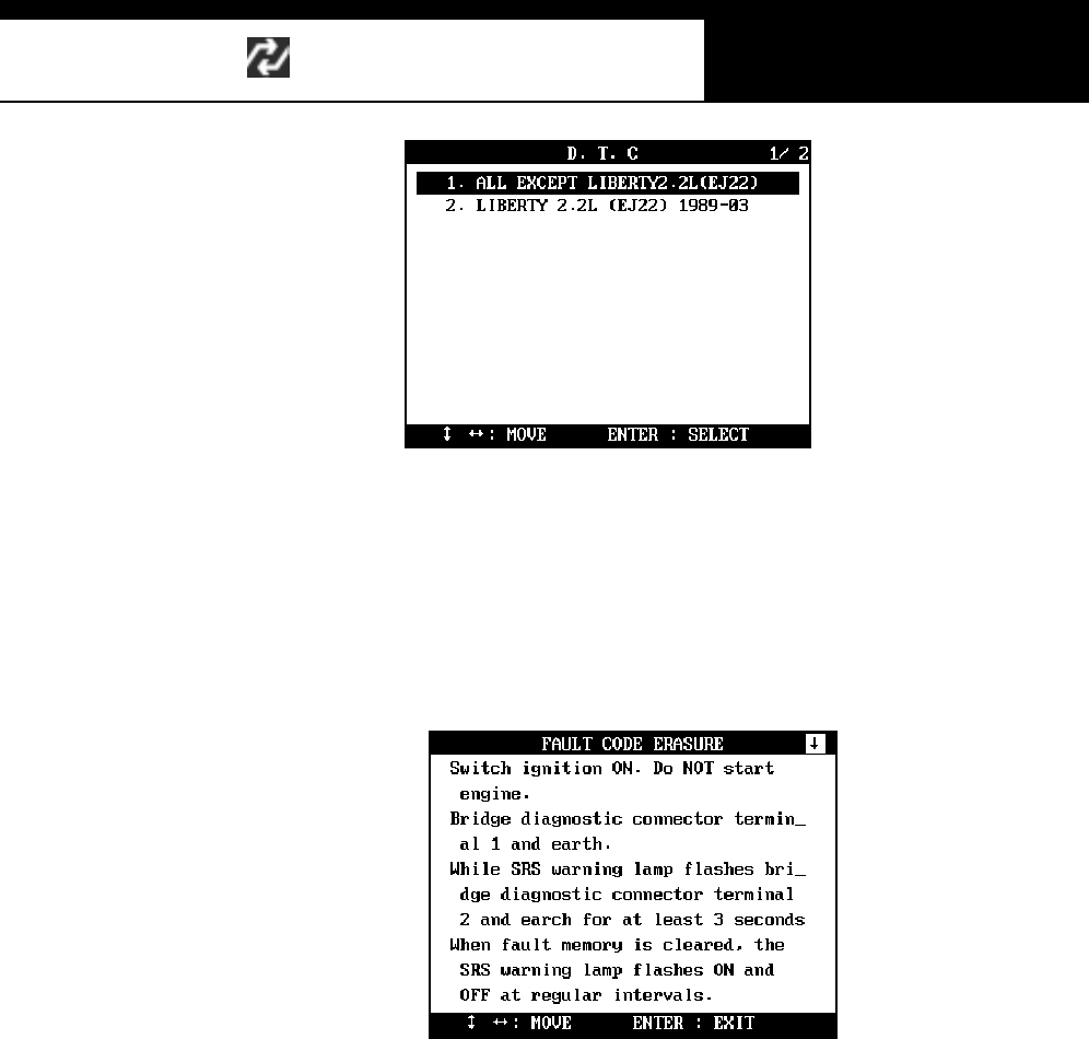
HANA TECH CO., LTD. Chapter 6
G
j G]G TG]^G
c ALL EXCEPT LIBERTY 2.2L (EJ22)
Select this item f rom the m enu to erase faul t code(s ) of all Subaru cars
except Liberty 2.2L(EJ22). Following instruction will appear.
-Turn the ignition key ON without starting engine. Bridge
terminal 1 of the connector and earth. The SRS warning
lamp will begin t o fl as h.
-Bridge terminal 2 and earth while the SRS warning lamp
fl ashes for at least 3 s econds, then the faul t memory will be
cleared.
-When the fault code is erased, the SRS warning lamp flashes
ON and OFF on regular intervals.
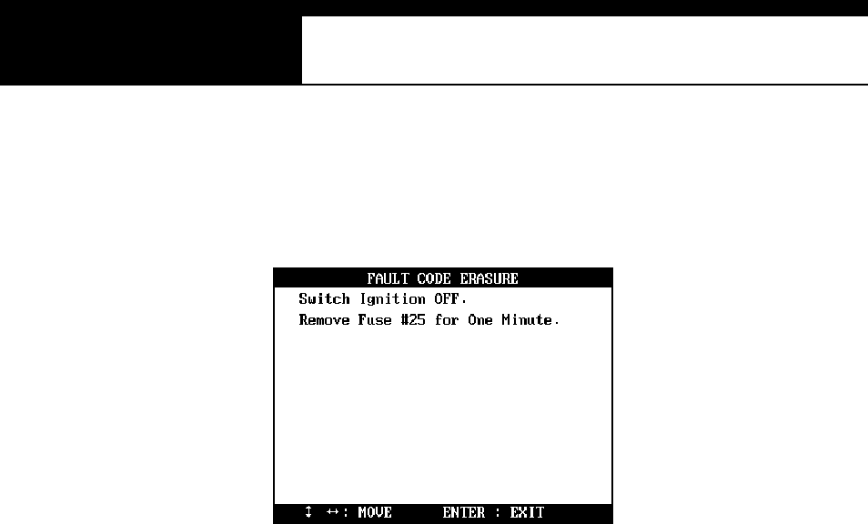
USER MANUAL For DCN Scanners
G
j G]G TG]_G
d LIBER TY 2.2L (EJ22)
Select this item from the menu to erase fault code(s) of Subaru Liberty
2.2L(EJ22). Following instruction will appear.
-Turn the igniti on key OFF.
-R em ove Fuse #25 for one m inute.

HANA TECH CO., LTD. Chapter 6
G
j G]G TG]`G
G
E. Uni den ti fied s ys te m ID
1. System ID Check
As explained herein, Multiscan automatically checks the system ID when you
select a control system and sets up the communication with the control
module thereupon. Multiscan SUBARU software contains thousands of
system ID, however, it is still possible that you encounter a SUBARU car of
which s ys tem ID is not i ncl uded in the Multis can sof tware databas e.
2. Cooperation for update
When Multiscan encounters a system ID that is not included in its data base,
it shows the detected system ID and communication features. If you
encounter these systems, contact your local distributor, and the system ID
will be relayed to Hanatech for a future update.
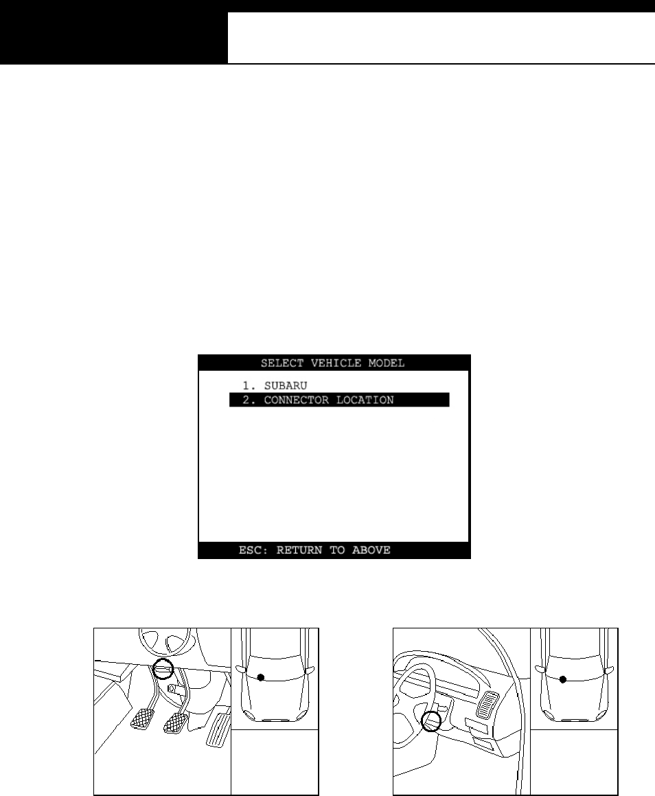
USER MANUAL For DCN Scanners
G
j G]G TG^WG
F. Adapter location
a The location drawings are purely from the experience of Hanatech and
provided for your reference only.
b The drawings are based on Right Hand Drive cars, therefore, you may
have to consider the mirror image for any Left Hand Drive cars.
c You can view these drawings on the Multiscan screen by selecting
[2.Connector Location] after selecting [SUBARU] from the car make list.

G
G
ٻ
ٻ
ٻ
ٻ
CHAPTER 7 KOREAN CARS
I. BACKGROUND …………. 7 – 1
II. REGIONAL DIFF ERENCES …………. 7 – 2
III. HYUNDAI …………. 7 – 4
IV. KIA …………. 7 – 14
V. DAEWOO …………. 7 – 24
VI. SSANGYONG …………. 7 – 30
VII. S AMS UNG …………. 7 – 36
G
Han atech Co., Ltd. Chapter 7
G
jG^GTG XG
Korean Cars
G
I. BACKGROUND ------------------------------
Korean automotive industry has experienced rapid development and
progress both in size and technology in less than 15 years since its first fuel-
injection vehicle was introduced in 1987. During this relatively short history of
on-going experiments, Korean car makes implemented and tested control
systems from various suppliers such as Bosch, Siemens, VDO, Delphi,
Melco, etc. And they actually manufactured hundreds of different models
using different control systems throughout the relatively short industrial
history. From a scanner’s viewpoint, the genealogical chart of Korean cars is
very m uch complicated and it is difficult to provide sufficient coverage.
Hanatech, the manufacturer of Multiscan, has been developing aftermarket
scan tools from the very beginning of the fuel injection history of Korean cars
since late 80’s, and such accumulation of experience and know-how in
Korean domestic market enabled Multiscan to provide original equipment
level functions and coverage for all Korean cars.

USER MANUAL For Multiscan
G
jG^GTG YG
II. Regional differences --------------------------
Hyundai and Kia, the best selling Korean car makes, are manufacturing the cars
differently to m eet the emission related regulations of regional markets.
According to the target markets, cars of these two companies are categorized into
three groups: Korean domestic, North American and Non-USA exports.
Daewoo, Ssangyong and Samsung cars do not have such regional variations.
A. Korean Domestic
a. Korean cars sold in Korean domestic market.
b. Secondhand cars imported from Korea
B. USA (North American) Exports
a. Hyundai and Kia cars exported to USA, Canada and Mexico where strict
em ission regul ations are applied.
b. Hyundai and Kia s econdhand cars imported f rom USA, Canada and
Mexi co.
c. OBD2 compliant since 1996.
C. Non-USA E xports
a. Hyundai and Kia cars sold outside Korea other than North America.
b. Hyundai and Kia secondhand cars imported from outside Korea other
than North America.
c. Meets European OBD (EOBD)
Han atech Co., Ltd. Chapter 7
G
jG^GTG ZG
D. Used cars
A real problem is in developing countries where Korean secondhand cars
share big market portion
In these countries, the user may have to try all three regional versions unless
he knows where the car is originated.
E. Regional application
According to the regional markets, Multiscan PCMCIA cards for Korean cars
contain the combination of regional versions as shown below.
Car Make Regional Europe
Asia, Af ri ca,
Oceania
North
Am erica
South
America
Domestic ¥¥
USA ¥¥
Hyundai
Non-USA ¥¥
Domestic ¥¥
USA ¥¥
Kia
Non-USA ¥¥
Daewoo ¥¥¥¥
Ssangyong ¥¥¥¥
Samsung ¥¥
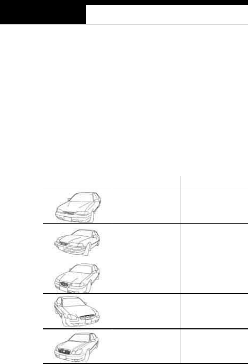
USER MANUAL For Multiscan
G
jG^GTG [G
III. HYUNDAI -------------------------------------
A. Vehicle Model Selection
1. Korean Domestic
a. In export markets, Hyundai has kept using a constant model name for a
cert ai n m odel quite long identi fying the details by the m odel year. To the
contrary, in Korean domestic market, Hyundai has named the same
model differently after applying a slight change in design and system .
For example, while Hyundai Sonata has been called Sonata for more
than 10 years in export market, they have changed the name at each
face-l ift and s ys tem change in Korea as shown below:
Export Model Name Domestic Model Name
SONATA
1989~1990 MY SONATA
SONATA
1991~1993 MY SONATA II
SONATA
1994~1998 MY SONATA III
SONATA
1999~2000 MY EF SON ATA
SONATA
2001 MY ~ NEW EF SON ATA
Han atech Co., Ltd. Chapter 7
G
jG^GTG \G
b. Since the model names are so diversified, you do not have to select a
model year when you are testing a Hyundai car of Korean domestic
version. It is directly followed by the system selection.
.
USER MANUAL For Multiscan
G
jG^GTG ]G
2. USA / NON-US A Exports
a. As explained above, in export market, Hyundai and Kia maintained the
same model name quite long, therefore, it is necessary to specify the
model year and other details to successfully establish communication
with the control module.
b. A detailed model name and model year listings are provided for your
s electi on, and followed by t he s ys tem s election.
Han atech Co., Ltd. Chapter 7
G
jG^GTG ^G
3. Model name comparison chart
<Based on Non-USA Exports>
Export Model Name Domestic Model Name
AT O S AT O S
GETZ C LICK
ACCENT 2003 NEW VERNA
ACCENT 2000~2002 VERNA
ACCENT or ECXEL 1995~1999 ACCENT
EXCEL 1990~1994 EXCEL
SCOUPE 1991~1996 SC OUPE
MATRIX LAVITA
ELANTRA 2001~2003 AVAN TE XD
ELANTRA 1996~2000 AVAN TE, ALL N EW AVAN TE
ELANTRA 1992~1995 ELANTRA
HD COUPE 2002~2003 TUSCANI
HD COUPE 1997~2001 TIBURON
SONATA 1999~2003 EF SONATA, NEW EF SONATA
SONATA 1994~1998 SONATA III
SONATA 1989~1993 SONATA, SONATA II
XG G R AND EUR XG
MARCIA MARCIA
CENTENNIAL EQUUS
GR ANDUER 1994~1998 N EW GRANDEUR
GR ANDEUR 1989~1993 G RANDEUR
H-100 1994~2001 GRACE
H-100 TRUCK 1997~2003 PORTER
H-1 1998~2003 STAREX
H-1 TRUCK 2001~2003 LIBERO
SANTAFE 2001~2003 SAN TAFE
TRAJET 2001~2003 TRAJET XG
TERRACAN 2001~2003 TERRACAN
GALLOPER GALLOPER I, II
SANTAMO SAN TAMO
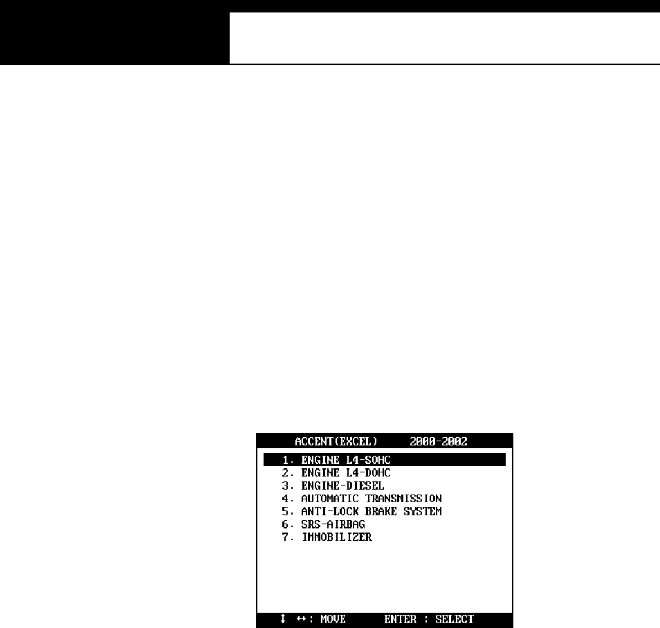
USER MANUAL For Multiscan
G
jG^GTG _G
B. System Selection
1. Select test system
a. When the model name and model year selections are made, Multiscan
proceeds to system selection menu.
b. Multiscan shows all possible systems that are available with the selected
vehi cle. The m enu generally has multiple Engine types for selection.
Any system shown in the menu does not mean that Multiscan confirms
actual existence of the system in the car.
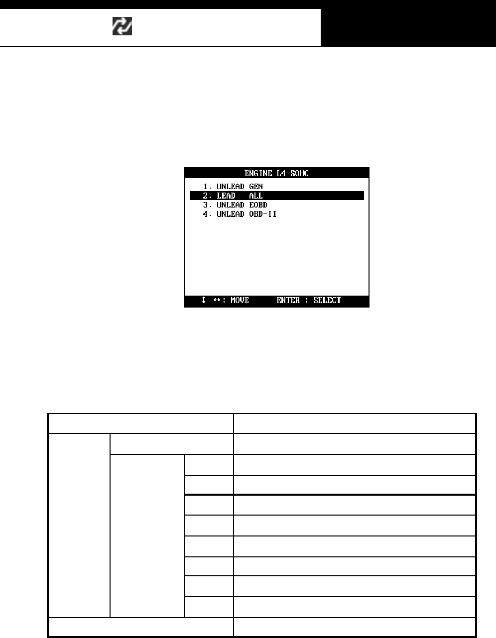
Han atech Co., Ltd. Chapter 7
G
jG^GTG `G
2. Engine type
a. When an engine control system is selected, another engine specification
s election menu fo llows as show n b elow:
b. There is a variety of engine specification according to the engine size,
model year, fuel type and regional emission regulations.
Following chart shows the examples of fuel type and emission
regulations that Multiscan Hyundai software presents for your selection.
Dies el Standard
LEAD ED Standa rd
GEN General – Except Europe and North America
ALL All countries
CAL Subject to C alif ornian emissi on regulations
KO R Subject to Korean emission control guideli ne
FED Subject to US Federal emission regulations
OBD-II Subject to O BD-II requirem ents
EOBD Subject to European OBD requi rements
Gasoline
UN LEADED
IMM Vehicle with Immobilizer system
LPG Liquefied Petroleum Gas vehicles – Standard
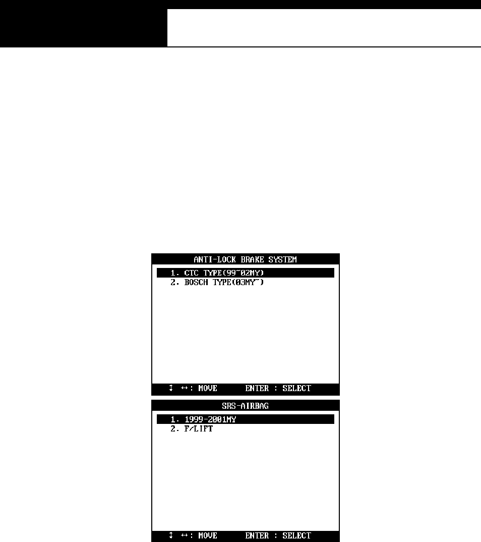
USER MANUAL For Multiscan
G
j G^G TGXWG
3. Uncertain details – Trial and error
a. It is easy to know the engine size, m odel year and fuel type, however,
identifying the appli ed emissi on regulati ons is diffi cul t f or an independent
works hop techni ci an.
b. The other control s ys tem s such as ABS and SRS also may as k your
further detailed selection as below:
c. You have to fi nd the correct selection by t rial and error when it is not
cl ear whi ch one to s elect.
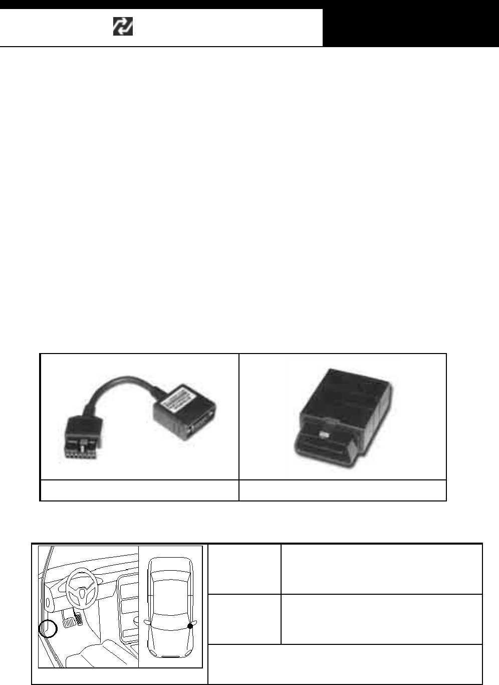
Han atech Co., Ltd. Chapter 7
G
j G^G TGXXG
G
C. Diagnostic Adapter Location
a. The DLC adapter location drawings are purely from t he experience of
Hanatech and provided for your reference only.
b. The drawings are based on Left Hand Drive cars, therefore, you may have to
consider the mirror image for the Right Hand Drive cars.
c. You can view these drawings on the Multiscan screen by selecting
[3.Connector Location] after sel ecting [Hyundai (Dom es tic / Non-USA / USA)]
from the car make list.
12-pin Mitsubishi / Hyundai adapter 16-pin OBD2 adapter
Export
name
Excel, Scoupe, Sonata (~`98),
Marcia, LPG Taxi, H-100 Truck, H -1,
Santamo, Elantra(~`95), Grandeur
Domestic
name
Excel, Scupe, Tiburon, Sonata I, II,
III, Marcia, LPG Taxi, Porter, Starex,
Santamo, Elatra, Grandeur
Adapter type: Hyundai 12-pin Adapter
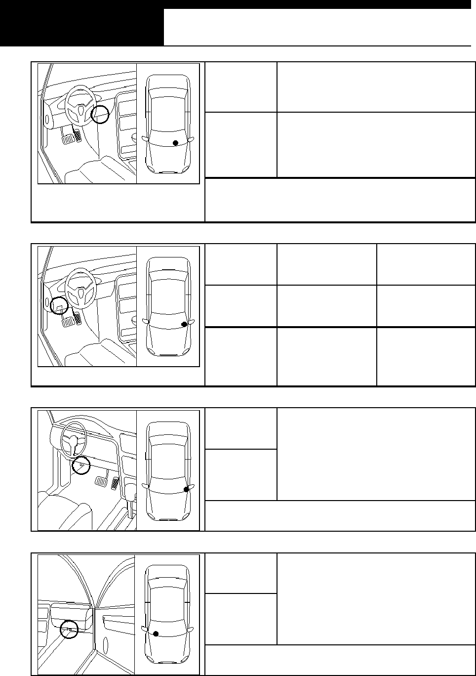
USER MANUAL For Multiscan
G
j G^G TGXYG
Export
name
Atos, Elantra(`96~), Sonata(`99~),
XG, Accent(2000~), Matrix, Trajet,
SataFe, Centennial, H-1 Truck
Domestic
name
Atos, Avante, Avante XD,
EF Sonata, N ew EF Sonata,
Grandeur XG, Verna, Lavita,
Trajet XG, Santa Fe, Equus , Libero
Adapter type: OBD2 16-pin Adapter
* Some of Av ant e (Elantra 96~0 0) hav e 12-pin adapter.
* H-1 Truck (Liber o) uses 12- pi n adapt er
Export
name
Accent (2000~) Accent (~`99)
Domestic
name Verna Accent
Adapter
Type
OBD2 16-pin
adapter
Hyundai 12-pin
adapter
Export
name
Domestic
name
New Grandeur, Dynasty, New
Dynasty, Santamo (2000)
Adapter type: Hyundai 12-pin Adapter
Export
name
Domestic
name
Galloper II
Adapter type: Hyundai 12-pin Adapter

Han atech Co., Ltd. Chapter 7
G
j G^G TGXZG
D. Coverage
All Hyundai cars

USER MANUAL For Multiscan
G
j G^G TGX[G
IV. KIA ----------------------------------------------
A. Vehicle Model Selection
1. Model Name
G
Kia’s model naming practice is no less complicated than Hyundai. Kia names
most of their cars differently in export and domestic market. And they even
name a same car differently according to the target market. This brings about
confusion in selecting proper model name, especially where new and secondhand
Kia cars are found mixed in the market.
Refer to the following model name comparison chart to make proper model name
selection when using Multiscan.
Model Name
Domestic Export
Pride(Hatch back)
Pride ȕ(Sedan)
Ford Festiva
Pride
Multiscan Model selection
Domestic USA / Non-USA
Pride Pride
Model Name
Domestic Export
Avella (Hatch back)
Avella Delta(Sedan)
Ford Festiva
Ave ll a
Multiscan Model selection
Domestic Non-USA / USA
Avella Avella
Han atech Co., Ltd. Chapter 7
G
j G^G TGX\G
Model Name
Domestic Export
Ri o
Rio SF Rio
Multiscan Model selection
Domestic Non-USA / USA
Ri o / Rio SF Rio
Model Name
Domestic Export
Sephia
Sephia II
Sephia
Mentor
Multiscan Model selection
Domestic Non-USA / USA
Sephia / Sephia II Sephia
Model Name
Domestic Export
Spectra Sephia II
Spectra
Multiscan Model selection
Domestic Non-USA / USA
Spectra Sephia
Model Name
Domestic Export
Shuma Sephia
Shuma
Multiscan Model selection
Domestic Non-USA / USA
Shuma Sephia / Shuma
USER MANUAL For Multiscan
G
j G^G TGX]G
Model Name
Domestic Export
Spectra Wing S h um a II
Spectra
Multiscan Model selection
Domestic Non-USA / USA
Spectra Shuma
Model Name
Domestic Export
Carens Carens
Multiscan Model selection
Domestic Non-USA / USA
Carens Carens
Model Name
Domestic Export
Sportage Sportage
Multiscan Model selection
Domestic Non-USA / USA
Sportage Sportage
Model Name
Domestic Export
Credos
Credos II Clarus
Multiscan Model selection
Domestic Non-USA / USA
Credos / Credos II Clarus
Han atech Co., Ltd. Chapter 7
G
j G^G TGX^G
Model Name
Domestic Export
Optima
O p tim a R eg al
Optima
Magentis
Multiscan Model selection
Domestic Non-USA / USA
Optima
O p tim a R eg al Optima(Magentis)
Model Name
Domestic Export
Elan
(Lotus) Elan
Multiscan Model selection
Domestic Non-USA / USA
Elan Elan
Model Name
Domestic Export
Potentia Potentia
Multiscan Model selection
Domestic Non-USA / USA
Potentia Potentia
Model Name
Domestic Export
Enterprise Enterprise
Multiscan Model selection
Domestic Non-USA / USA
Enterprise Enterprise
USER MANUAL For Multiscan
G
j G^G TGX_G
Model Name
Domestic Export
Carnival Sedona
Carnival
Multiscan Model selection
Domestic Non-USA / USA
Carnival Carnival(Sedona)
Model Name
Domestic Export
Retona Military 4WD
- KM42 Series
Multiscan Model selection
Domestic Non-USA / USA
Retona Retona
Model Name
Domestic Export
Carstar Joice
Multiscan Model selection
Domestic Non-USA / USA
Carstar Joice
Model Name
Domestic Export
Pregio Pregio
Multiscan Model selection
Domestic Non-USA / USA
Pregio Pregio
Han atech Co., Ltd. Chapter 7
G
j G^G TGX`G
Model Name
Domestic Export
Bongo Truck
Bongo Frontier
Frontier
K2700
Multiscan Model selection
Domestic Non-USA / USA
Frontier Frontier
Model Name
Domestic Export
S orento Sorento
Multiscan Model selection
Domestic Non-USA / USA
S orento Sorento
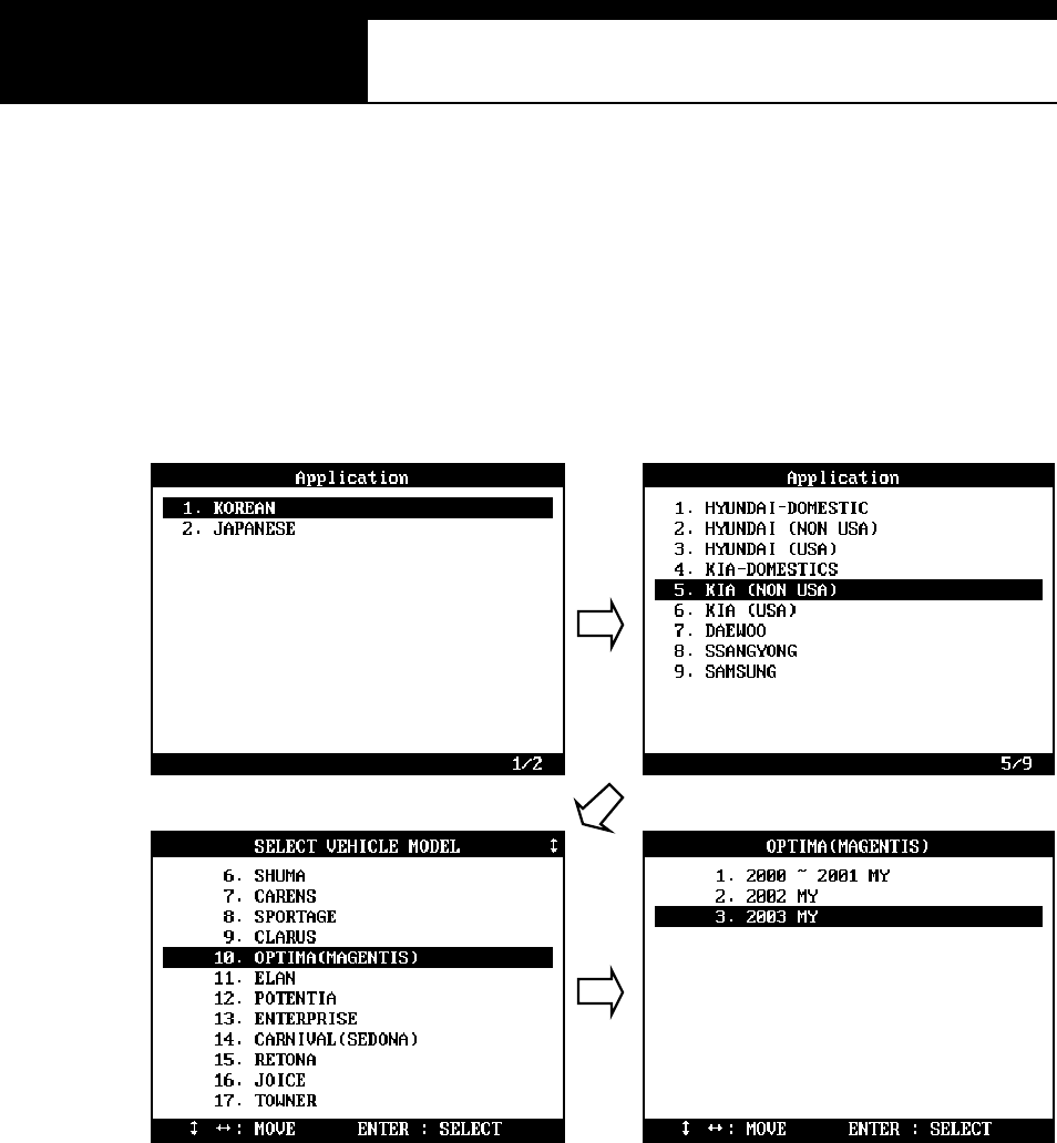
USER MANUAL For Multiscan
G
j G^G TGYWG
B. System Selection
1. Select test system
a When the model name and model year selection are made, Multiscan
proceeds to the system selection menu.
b Multiscan shows all possible systems that are available with the selected
vehicle.
Any system shown in the menu does not mean that Multiscan confirms
actual exis t ence of the sys tem in the car.
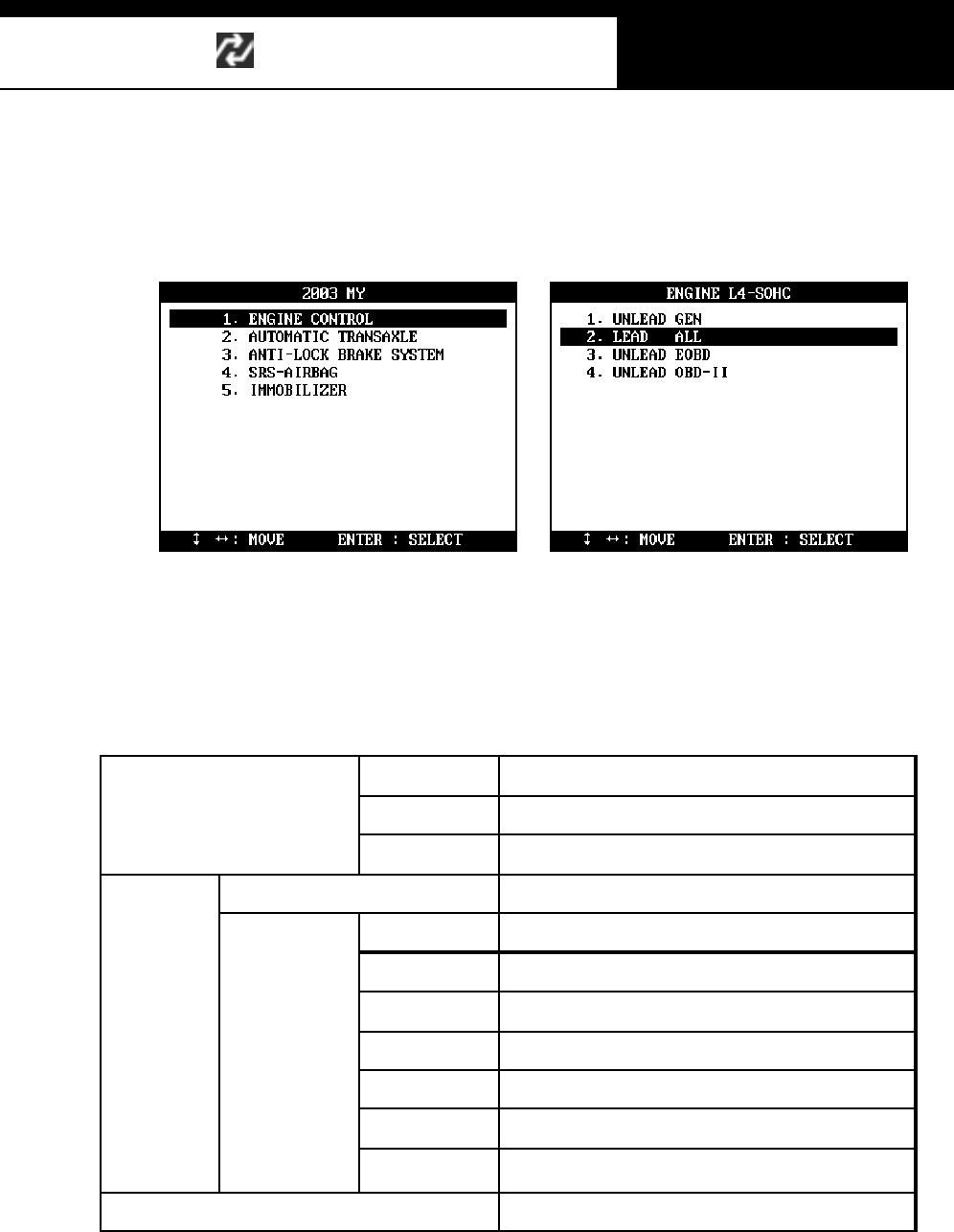
Han atech Co., Ltd. Chapter 7
G
j G^G TGYXG
2. Engine type
a When an engine control system is selected, another engine specification
s ele c ti on m e nu fo ll o ws as s h ow n b el o w:
b There is a variety of engine specification according to the engine size,
model year, fuel type and regional emission regulations.
Following chart shows the examples of fuel type and emission
regulations that Multiscan Hyundai software presents for your selection.
EUROPE Meets European emission regulations
GENERAL All countries
Diesel
C/RAIL Common Rail Injection type
LEADED Standard
EURO III, I V Meets European emission regulations
GENERAL All countries
MELCO Control module m anufactured by MELCO
BOSCH Control module m anufactured by BOSCH
NON IMMO Vehicle without Imm obi lizer
W / IMMO Vehicle with Im mobilizer
Gas oli ne UNLEADED
TED One of KIA’s m odel codes (project name)
– no special meaning
LPG Liquefied Petroleum Gas vehicles – Standard
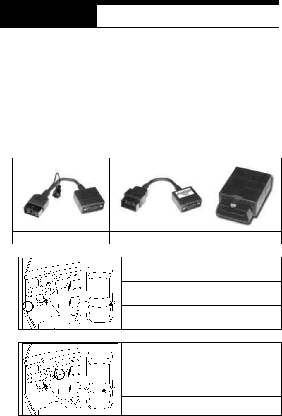
USER MANUAL For Multiscan
G
j G^G TGYYG
C. Diagnostic Adapter Location
a. The DLC adapter location drawings are purely from the experience of
Hanatech and provided for your reference only.
b. The drawings are based on Left Hand Drive cars, therefore, you may have to
consider the mirror image for the Right Hand Drive cars.
c. You can view these drawings on the Multiscan screen by selecting
[3.Connector Location] after selecting [KIA (Dom estic / Non-USA / USA)] from
the car make list.
14-pin circular adapter 20-pin adapter 16-pin OBD2 adapter
Export
name Joice
Domestic
name C ars tar
Adapter type: Hyundai 12-pin
Export
name Optima (Magentis), Visto
Domestic
name Optima, Optima R egal , Visto
Adapter type: OBD2 16-pin
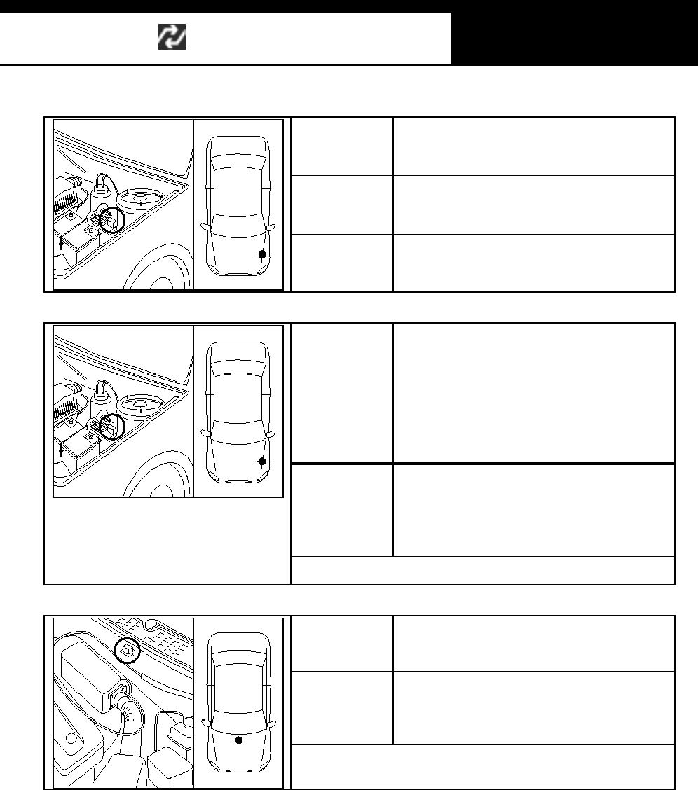
Han atech Co., Ltd. Chapter 7
G
j G^G TGYZG
Export
name Ford Festiva, Captial, Concord
Domestic
name
Pride, Avella, Capital, Concord
Adapter
Type Adapter type: KIA/MAZDA 6-pin
Export
name
Carens, Potentia, Credos (Clarus),
Sportage, Shuma (Sephia), Elan,
Carnival (Sedona), Rio, Rio SF,
R etona (KM42), Enterpris e,
Sephia II, Shuma II, Sorento,
Optima (Magentis)
Domestic
name
C arens , Potentia, Credos , Sportage,
Shuma, Shuma, Elan, Carni val , Rio,
R etona, Enterprise, Spectra,
Sorento, Optima
Adapter type: KIA 20-pin
Export
name Sephia, Sephia II, Mentor, Timor
Domestic
name Sephia, Sephia II
Adapter type: KIA 20-pin
D. Coverage
All Kia cars
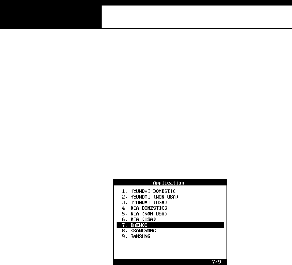
USER MANUAL For Multiscan
G
j G^G TGY[G
V. DAEWOO -------------------------------------
A. Vehicle Model Selection
1. Re gio nal Varia tio n
Differently from Hyundai or Kia, Daewoo has no regional variations. Korean
domestic version software is compatible with export models, too.
Therefore, Multiscan Korean car software package includes Daewoo
domestic version codes only.
2. Model Name
G
Daewoo has few variations in model naming when compared with Hyundai or
Kia. Most of Daewoo cars share the same name regardless of manufacturing
place and regional market except for Lemans and Cielo.
a Lemans
Introduced in 1986 based on Opel Cadet 1.6 or Pontiac Lemans, and
started to implement TBi fuel injection system since 1988. Export model
name was Racer.
b Cielo
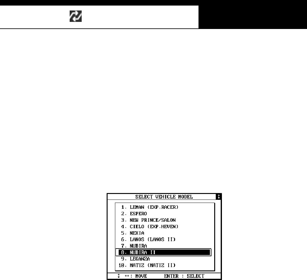
Han atech Co., Ltd. Chapter 7
G
j G^G TGY\G
Daewoo renamed Lemans to Cielo after face-lifting. Cielo was also
manufactured in their overseas plants in India and Uzbekistan. Both of
“Cielo” and “Heaven” were used for export models. Lemans and Cielo
were replaced by Lanos in 1997.
c Ssangyong cars
Ssangyong cars once had been sold through Daewoo dealer networks
for a few years in late 90’s, and most of Ssangyong cars manufactured
in this period were wearing Daew oo em blems .
You should choose Ssangyong in the car m ake menu to diagnose these
cars : Musso, MB100 (Istana), Chairman, Korando.
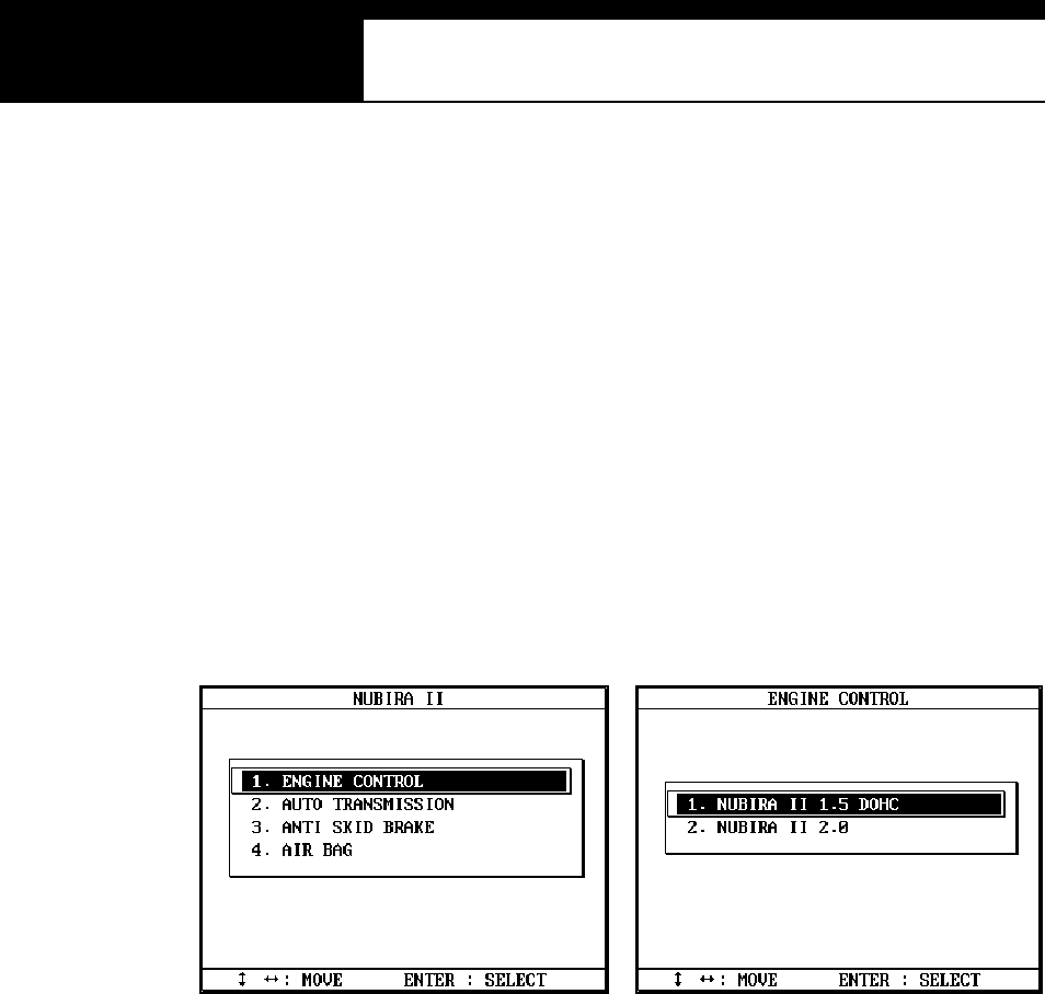
USER MANUAL For Multiscan
G
j G^G TGY]G
B. System Selection
G
1. Menu Se lection
A s ys tem selection menu promptly foll ows the model name s el ection.
Mul tis can Daewoo s oftw are does not require you to make s electi ons am ong
complicated model codes and applied emission regulations.
A simple engine size and model year selection menu follows when [Engine
control] system is selected.
2. Auto Transmission
Until late 1990’s, “New Prince / Salon” of Daewoo had mechanical type
automatic transmission, not the electronic control type. These mechanical
types are not subject to scanner communication.
Han atech Co., Ltd. Chapter 7
G
j G^G TGY^G
3. Supported systems and coverage
Model Name ENGINE A/T ABS SRS ISU
LEMAN S (R AC ER ) ¥
ESPERO ¥¥¥
N EW PR ICE / SALON ¥¥
C I ELO (HEAVEN ) ¥¥¥
N EXIA ¥¥¥
LANOS I / II ¥¥¥¥
NUBIRA I / II ¥¥¥¥
LEGANZA ¥¥¥¥
MATIZ I / II ¥¥¥¥
MAGNU S ¥¥¥¥ ¥
DAMAS/LABO ¥
TICO ¥
REZZO ¥¥¥¥
C. Func tio n Selection
G
All Daewoo cars support DTC read / erase and data stream functions. Please
refer to the previous chapter for detailed operations of each function.
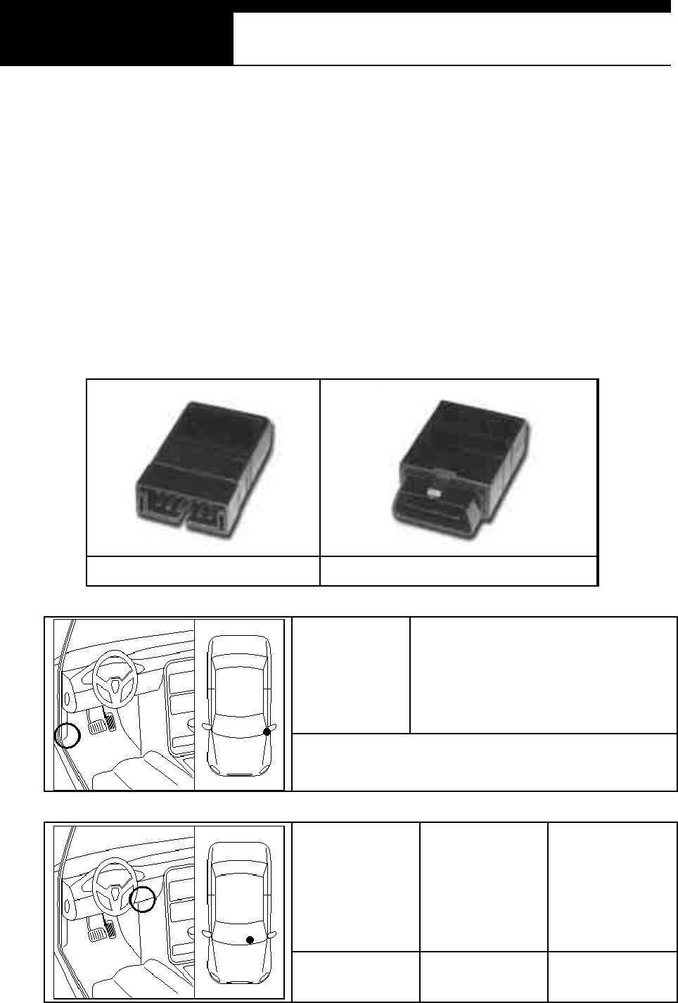
USER MANUAL For Multiscan
G
j G^G TGY_G
D. Diagnostic Adapter Location
a. The DLC adapter location drawings are purely from the experience of
Hanatech and provided for your reference only.
b. The drawings are based on Left Hand Drive cars, therefore, you may have to
consider the mirror image for the Right Hand Drive cars.
c. You can view these drawings on the Multiscan screen by selecting
[3.Connector Location] after selecting [DAEWOO VEHICLES] from the car
make list.
12-pin adapter 16-pin OBD2 adapter
Model Name NUBIRA II
Adapter type: OBD2 16-pin
Model Name Magnus Leganza
Adapter type OBD2 16-pin DAEWOO
12-pin
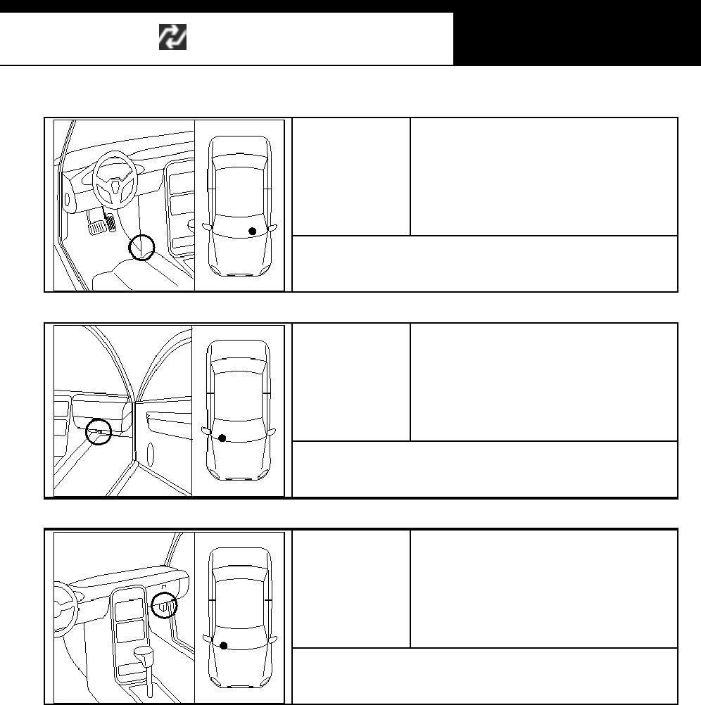
Han atech Co., Ltd. Chapter 7
G
j G^G TGY`G
Model N am e Damas, Labo
Adapter type: DAEWOO 12-pin
Model Name Matiz
Adapter type: DAEWOO 12-pin
Model Name
Lemans(Racer), Espero,
New Price / Salon, Cielo(Heaven),
Nexi a, Ti co, Lanos , Nubira
Adapter type: DAEWOO 12-pin
E. Coverage
All Daewoo cars
Refer t o the [B-3. Supported System s and Coverage] f or furt her inform ation.
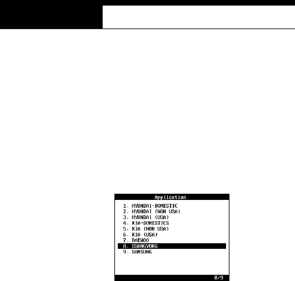
USER MANUAL For Multiscan
G
j G^G TGZWG
VI. SSANGYONG --------------------------------
A. Vehicle Model Selection
1. Re gio nal Varia tio n
Ssangyong has no regional variations. Korean domestic version software is
compatible with export models, too.
Therefore, Multiscan Korean car software package includes Ssangyong
domestic version codes only.
2. Model Name
G
a Ssangyong has only one variation in model naming: Istana, a van sold
under Mercedes Benz brand, called MB100 in export market.
b Ssangyong cars with Daewoo emblem
Ssangyong cars once had been sold through Daewoo dealer networks
for a few years in late 90’s, and most of Ssangyong cars manufactured
in this period were wearing Daew oo em blems .
Even though the car may have Daewoo marks in the front and rear, you
s hould choose Ss angyong i n the car make m enu to diagnos e thes e cars
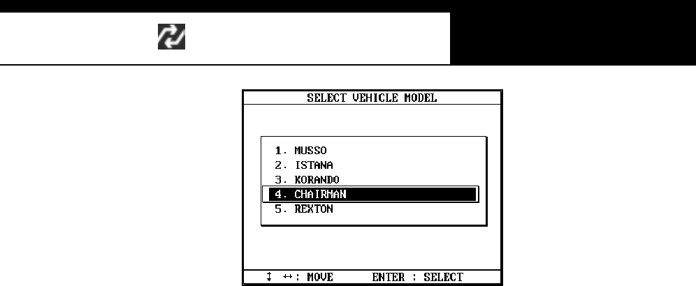
Han atech Co., Ltd. Chapter 7
G
j G^G TGZXG
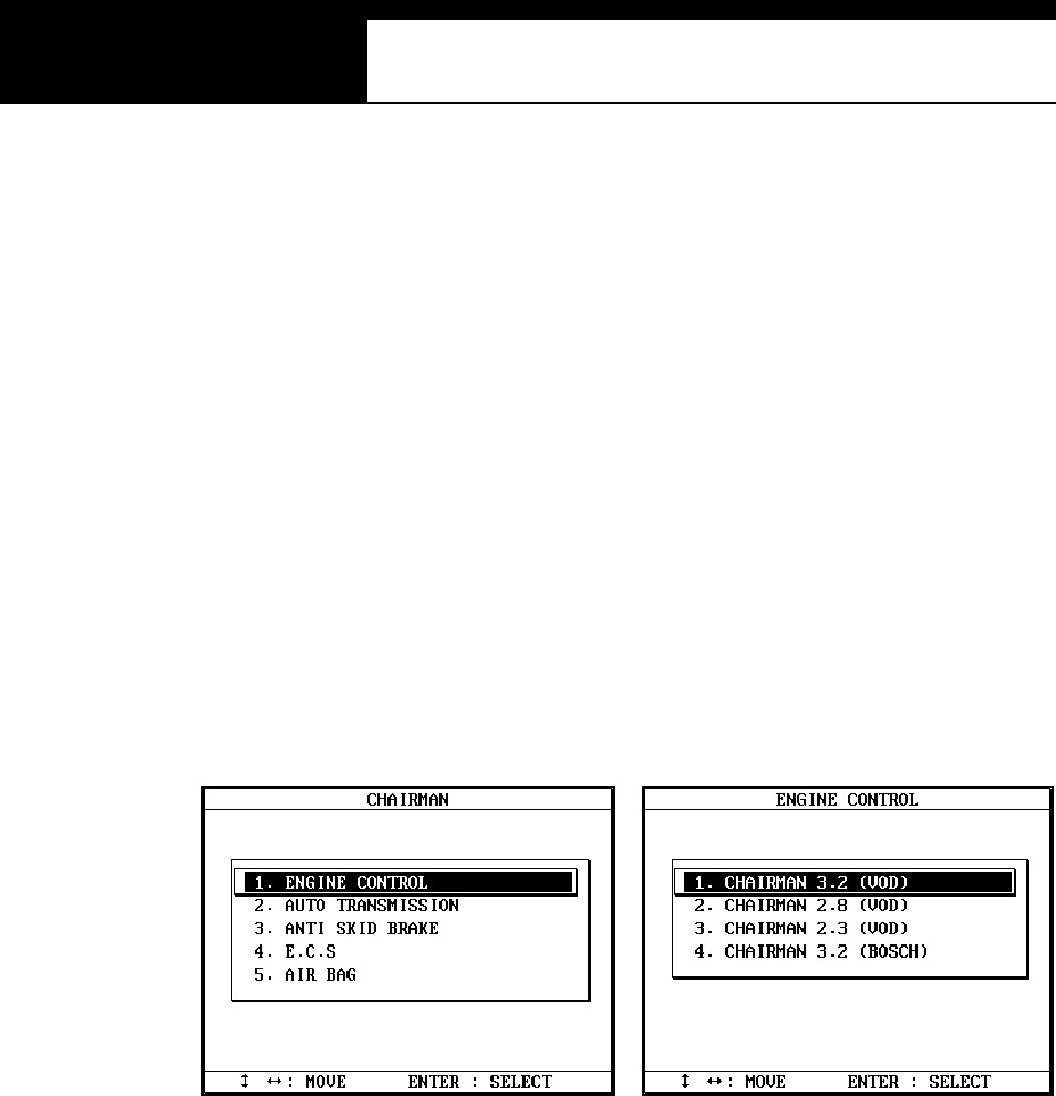
USER MANUAL For Multiscan
G
j G^G TGZYG
B. System Selection
a A system selection menu promptly follows the model name selection.
Multiscan Ssangyong software does not requi re you to m ake s electi ons
among complicated model codes, system version and applied emission
regulations at this stage.
b When a system is selected, a detailed specification menu follows.
c Diesel powered Ssangyong cars still do not have electronic control unit,
therefore, only gasoline vehicles are available with scanner
communication.
Han atech Co., Ltd. Chapter 7
G
j G^G TGZZG
C. Supported systems
Model Name ENG A/T ABS ECS SRS TOD TCCU
MU SSO ¥¥¥¥¥¥¥
ISTANA(MB100) ¥
KORANDO ¥¥¥¥¥¥¥
CH AI R MAN ¥¥¥¥¥
REXTON ¥¥¥ ¥¥¥
D. Func tio n Selection
G
All Daewoo cars support DTC read / erase and data stream functions. Please
refer to the previous chapter for detailed operations of each function.
TCCU system may support DTC reading function onl y.
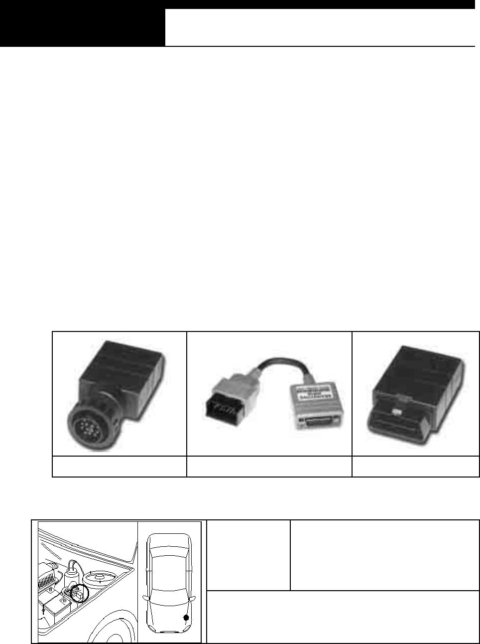
USER MANUAL For Multiscan
G
j G^G TGZ[G
E. Diagnostic Adapter Location
a The DLC adapter location drawi ngs are purely f rom the experience of
Hanatech and provided for your reference only.
b The drawings are based on Left Hand Drive cars, therefore, you may
have to consider the mirror image for the Right Hand Drive cars.
c You can view these drawings on the Multiscan screen by selecting
[3.Connector Location] after selecting [DAEWOO VEHICLES] from the
car m ake lis t .
14-pin circular adapter 20-pin adapter 16-pin OBD2 adapter
Model Name Korando, Musso (before 1999)
Adapter type: 14-pin circular or 20-pin
Han atech Co., Ltd. Chapter 7
G
j G^G TGZ\G
Model Name Chairman
Adapter type: 14-pin circular
You have to remove the plastic cover
Model Name Istana (MB100)
Adapter type: 14-pin circular
This dra wing i s base d on passe nger car.You may have to
access the adapter t hr ough the engin e compar tment f or t his
kind of v an.
Model Name Musso, Rexton
Adapter type: 16-pin OBD2
F. Coverage
Refer to the [C. Supported Systems] section hereinbefore.

USER MANUAL For Multiscan
G
j G^G TGZ]G
VII. SAMSUNG ----------------------------------
A. Background
Renault-Nissan-Samsung
a Samsung motor company’s official name is Renault-Samsung motor
company, and is a family of Renault-Nissan network, and manufactures
knockdown models of Nissan cars in the assembly plant in Korea.
Samsung has two models of SM5 and SM3, which are the same as
Nissan Maxima and Bluebird.
b The electronic control system of these Nissan cars are directly migrated
to Samsung cars wi th leas t modifi cation, and therefore, the s canner
communication is the same as ordinary Nissan cars.
Refer to the Nissan section in the previous chapter for further information.
c The licensed models are basically prohibited to sell in other countries,
therefore, Samsung cars are found in a few limited countries.
Samsung SM5 being sold in Chile is renamed to SQ5.
B. Supported Systems
Model Name ENGINE A/T ABS SRS IVMS
SM5 (SQ 5 ) ¥¥¥¥ ¥
SM3 ¥¥¥¥
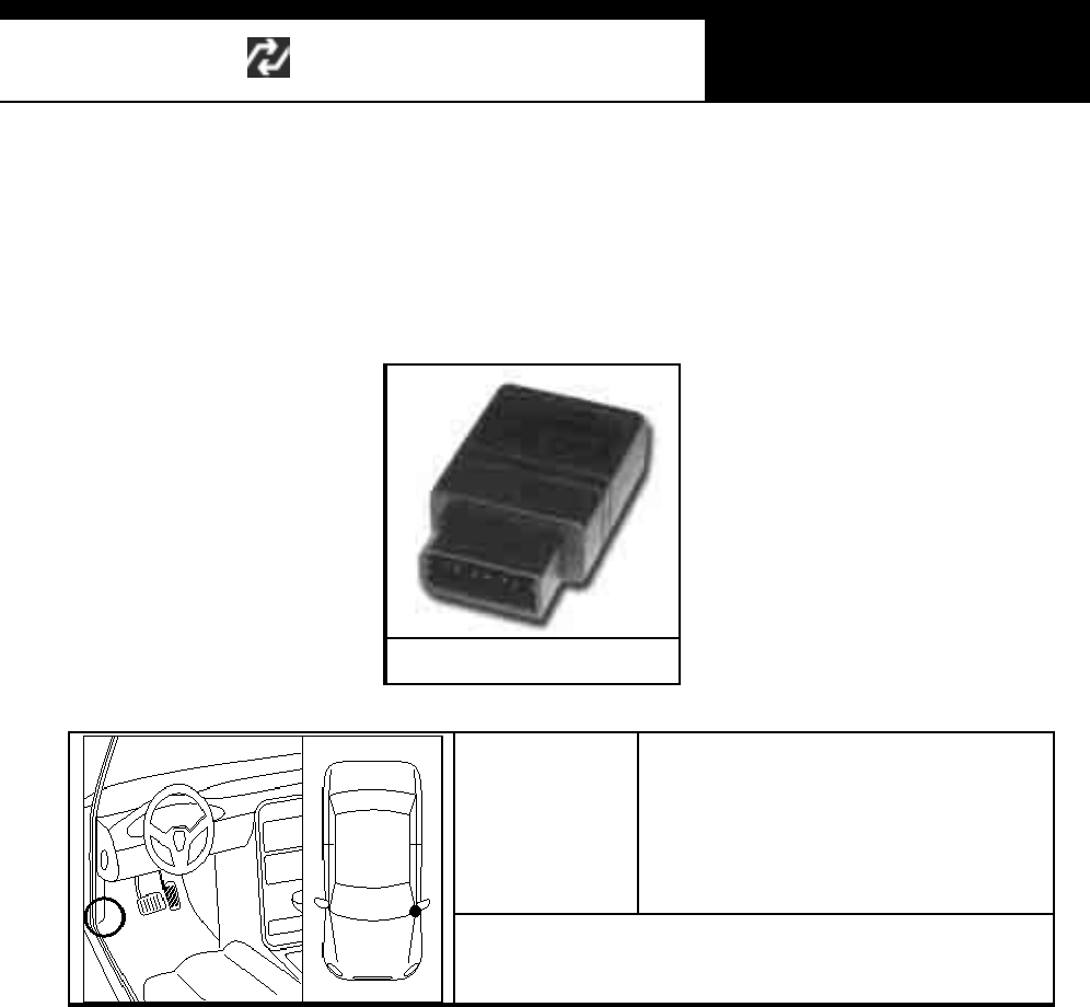
Han atech Co., Ltd. Chapter 7
G
j G^G TGZ^G
C. Diagnostic Adapter Location
Samsung cars use 14-pin Nissan adapter found in only one location.
14-pin Nissan adapter
Model Name SM5 (SQ5), SM3
Adapter type: 14-pin Nissan

G
G
ٻ
ٻ
ٻ
ٻ
CHAPTER 8 TROUBLE SHOOTING
Would not turn on when the power key is pressed …. 8 – 2
P ower automatically turns off after turned on …. 8 – 3
LCD screen problem s …. 8 – 4
Communication Error …. 8 – 5
G
G

Han atech Co., Ltd. Chapter 8
G
jG_GTG XG
Trouble Shooting
G
G
This part of manual presents you the instant actions to be taken for
the most frequently reported troubles.
The purpose of this troubleshooting guide is to minimize the loss of
tim e and cos t caus ed by dis puting of troubles that can be sim ply
solved by the user himself.
Please always refer to this troubleshooting guide and do as
s ugges ted herein when you have any trouble while using Mul tis can
equipment in advance to calling up your local distributor.
The manufacturer keeps endeavoring to minimize the possible
troubles, therefore, remedies to prevent listed problems can be
made without notice to individual users.
Note your local distributor’s contact information here:
G
G
G
G
G
USER MANUAL For Multiscan
G
jG`GTG YG
Would not turn on when the power is supplied
Check the power cable connection
NO . It w as not properly connectedY E S. Th e cab le is f irmly co nn ect ed
Reconnect t he power cable firmly
NO. It still does not work
Check if the red LED’s on both
ends of the power cable are ON
Both LED’s are ON Only one LED is ON Both LED’s are OFF
Replace the power Cable
Open the cigar ett e lighter socket ,
and check if the fuse is blown
It is O .K. It is Blown
Replace the fuseCheck the battery voltage
It is les s t han 8~10V It is more than 8V
Vehicle Battery Voltage is too LOW Contact local distribut or
Mult i scan is no t def ec tive
Try again with the other vehicle
The unit may not respond to the key input due to
internal keypad connection failure. The distributor
m ay have to open the head unit to check the
connection. Report the symptoms to your local
distributor and wait for the instruction.
G
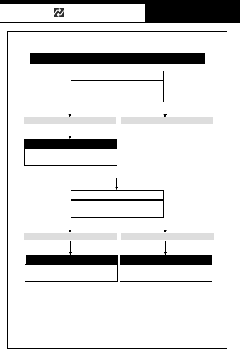
Han atech Co., Ltd. Chapter 8
G
jG_GTG ZG
Power automatically turns off after turned on
Report to your local distributor
The distributor may have to replace the main
board. Report the symptoms to your local
distributor and wait for our instruction
Check the battery voltage
Multiscan requires the power of 8V or higher for
proper operation. Insufficient vehicle battery
voltage m ay result in prom pt system turn off.
Check the vehicle battery voltage
It is normal. It is higher t han 10 VIt is lower than 10 V
Use the other power source
Replace the vehicle battery with fresh new one.
Or use external vehicle battery for temporary
power supply.
It is normal. It is higher than 600mAIt is lower than 600mA
Use the other power source
Replace the vehicle battery with fresh new one.
Or use external vehicle battery for temporary
power supply.
Check the power Amperage
Multiscan requires the power of 600mA or more
for proper operation. Insufficient power amperage
may result in prompt system turn off.
G
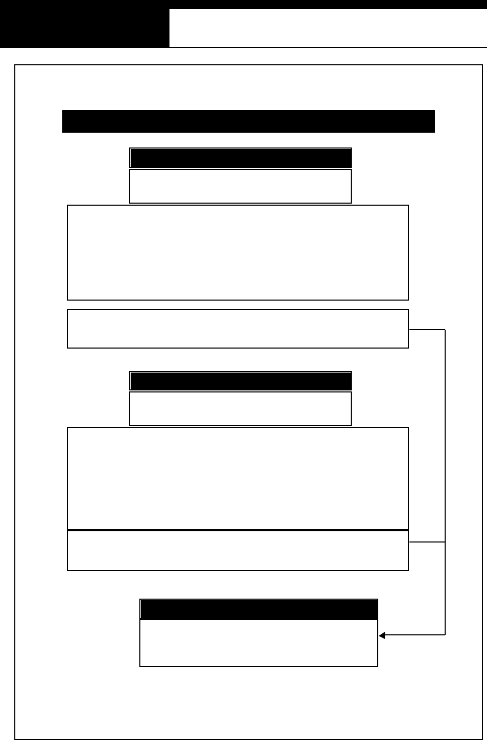
USER MANUAL For Multiscan
G
jG`GTG [G
LCD screen problems
Adjust the contrast using the contrast
wheel on the right side of Multiscan
LCD s tands for Liquid Crystal Display, and it is very sensitive to
temperature.
If you have placed Multiscan in a cold or hot place, the display may
become too dim or too dark when turned on. This is not a defect of
Multiscan, but a normal response of all LCD’s to the change of
temperature.
However, if you cannot control the contrast using the dial, please
contact us for further assistance.
The display is t oo dim or too dark
Adjust the contrast using the contrast
wheel on the right side of Multiscan
The LCD unit of Multiscan has a backlight for brighter display. This
backlight generates heat as time elapses when turned on.
As mentioned above, because LCD is sensitive to temperature, the
part of the LCD near the backlight may turn dark when you keep
Multiscan turned on for more than 2 hours.
This is not a defect of Multiscan.
H owe ver, if the LC D becomes da rk too ear ly or the contrast a djustment
doesn’t work, please contact us for further assistance.
A part of LCD became very dark
Report to your local distributor
If the problem is too serious to use properly or the contrast
dial does not function, report the symptoms to your local
distributor and wait for instruction.
Replac em ent of th e LC D mo d ule ma y b e nece ssary.
G
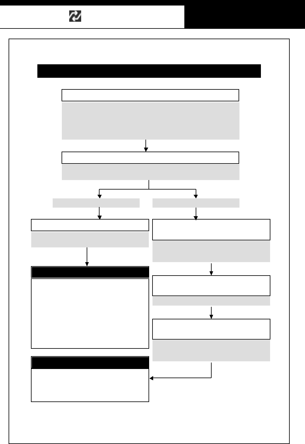
Han atech Co., Ltd. Chapter 8
G
jG_GTG \G
If you can find other vehicles of different make and
model, t ry to test with as m any c ars as poss ible.
Check the cable connection
Communication Error
Check if the car has any other
connector for communication
Check the followings
The main data link cable is firmly connected to the Multiscan.
The correct adapter is firmly connected to the main data link cable.
The adapter is firmly connected to the vehicle side connector.
A car may have multiple connectors for diagnostic
communication for different systems. Please try
with the other connector if available.
Check if the detailed vehicle
selection was correctly made
Please restart the vehicle selection procedure.
Check if the vehicle is included in
the coverage list
The applicable vehicle range is updated frequently.
Please consult your local distributor if the vehicle
is included in your current software version.
Try with the other vehicle
If you can find another vehicle of the different model that requires
the same adapter, please try again with the vehicle.
Yes, it works fine with the other carsNo, it doesn’t work, either
Try with t he other vehicles
Cable or Adapter is defective
If the communication error occurs with all
cars, we can conclude that the main data
link cable is defective.
If the communication error occurs with
vehicles using a specific adapter, the
adapter is r egarded defecti ve
Report the symptom to your local
distributor and wait for instruction.
Soft ware update is necessary
Please report your error to your local
distributor. We will revise the software
and let you have the updated software as
soon as it is released
G

USER MANUAL For Multiscan
G
jG`GTG ]G
ٻ
ٻ
ٻ
ٻ
ٻ
ٻ
Hanatech Co., Ltd.
Autom otive Diagnostic Equipment Specialist
ٻ
ٻ
ٻ
ٻ
ٻ
ٻ
oTiVkSG_WTXSGzTSG G
nTOnGPSGG
nTOnPSG
rUG
wGjaG^ZW`XZG
Phone: +82-54-454-9009
Fax: +82-54-454-8554
Website: http://www.hanatech.net
Copyright 2003 by Hanat ech Co., Ltd.
P ublished in Korea
G
G