Hangzhou Hikvision Digital Technology 16PK Keypad User Manual
Hangzhou Hikvision Digital Technology Co., Ltd. Keypad
Contents
- 1. User Manual
- 2. Users Manual
User Manual

Keypad User Manual
1
LCD Keypad
User Manual

Keypad User Manual
2
About this Manual
This Manual is applicable to LCD keypad.
The Manual includes instructions for using and managing the product. Pictures, charts, images and all
other information hereinafter are for description and explanation only. The information contained in
the Manual is subject to change, without notice, due to firmware updates or other reasons. Please
find the latest version in the company website (http://overseas.hikvision.com/en/).
Please use this user manual under the guidance of professionals.
Legal Disclaimer
REGARDING TO THE PRODUCT WITH INTERNET ACCESS, THE USE OF PRODUCT SHALL BE WHOLLY AT
YOUR OWN RISKS. OUR COMPANY SHALL NOT TAKE ANY RESPONSIBILITES FOR ABNORMAL
OPERATION, PRIVACY LEAKAGE OR OTHER DAMAGES RESULTING FROM CYBER ATTACK, HACKER
ATTACK, VIRUS INSPECTION, OR OTHER INTERNET SECURITY RISKS; HOWEVER, OUR COMPANY WILL
PROVIDE TIMELY TECHNICAL SUPPORT IF REQUIRED.
SURVEILLANCE LAWS VARY BY JURISDICTION. PLEASE CHECK ALL RELEVANT LAWS IN YOUR
JURISDICTION BEFORE USING THIS PRODUCT IN ORDER TO ENSURE THAT YOUR USE CONFORMS THE
APPLICABLE LAW. OUR COMPANY SHALL NOT BE LIABLE IN THE EVENT THAT THIS PRODUCT IS USED
WITH ILLEGITIMATE PURPOSES.
IN THE EVENT OF ANY CONFLICTS BETWEEN THIS MANUAL AND THE APPLICABLE LAW, THE LATER
PREVAILS.
0100001050519

Keypad User Manual
3
Regulatory Information
FCC Information
Please take attention that changes or modification not expressly approved by the party responsible for
compliance could void the user’s authority to operate the equipment.
FCC compliance: This equipment has been tested and found to comply with the limits for a Class B
digital device, pursuant to part 15 of the FCC Rules. These limits are designed to provide reasonable
protection against harmful interference in a residential installation. This equipment generates, uses
and can radiate radio frequency energy and, if not installed and used in accordance with the
instructions, may cause harmful interference to radio communications. However, there is no guarantee
that interference will not occur in a particular installation. If this equipment does cause harmful
interference to radio or television reception, which can be determined by turning the equipment off
and on, the user is encouraged to try to correct the interference by one or more of the following
measures:
—Reorient or relocate the receiving antenna.
—Increase the separation between the equipment and receiver.
—Connect the equipment into an outlet on a circuit different from that to which the receiver is
connected.
—Consult the dealer or an experienced radio/TV technician for help.
This equipment should be installed and operated with a minimum distance 20cm between the radiator
and your body.
FCC Conditions
This device complies with part 15 of the FCC Rules. Operation is subject to the following two
conditions:
1. This device may not cause harmful interference.
2. This device must accept any interference received, including interference that may cause undesired
operation
EU Conformity Statement
This product and - if applicable - the supplied accessories too are marked with "CE"
and comply therefore with the applicable harmonized European standards listed
under the EMC Directive 2014/30/EU, the RE Directive 2014/53/EU, the RoHS
Directive 2011/65/EU.
2012/19/EU (WEEE directive): Products marked with this symbol cannot be disposed
of as unsorted municipal waste in the European Union. For proper recycling, return
this product to your local supplier upon the purchase of equivalent new equipment,

Keypad User Manual
4
or dispose of it at designated collection points. For more information see: www.recyclethis.info.
2006/66/EC (battery directive): This product contains a battery that cannot be
disposed of as unsorted municipal waste in the European Union. See the product
documentation for specific battery information. The battery is marked with this
symbol, which may include lettering to indicate cadmium (Cd), lead (Pb), or mercury
(Hg). For proper recycling, return the battery to your supplier or to a designated collection point. For
more information see: www.recyclethis.info.
Industry Canada ICES-003 Compliance
This device meets the CAN ICES-3 (B)/NMB-3(B) standards requirements.
This device complies with Industry Canada licence-exempt RSS standard(s). Operation is subject to the
following two conditions:
(1) this device may not cause interference, and
(2) this device must accept any interference, including interference that may cause undesired
operation of the device.
Le présent appareil est conforme aux CNR d'Industrie Canada applicables aux appareils radioexempts
de licence. L'exploitation est autorisée aux deux conditions suivantes :
(1) l'appareil ne doit pas produire de brouillage, et
(2) l'utilisateur de l'appareil doit accepter tout brouillage radioélectrique subi, même si le brouillage
est susceptible d'en compromettre le fonctionnement.
Under Industry Canada regulations, this radio transmitter may only operate using an antenna of a type
and maximum (or lesser) gain approved for the transmitter by Industry Canada. To reduce potential
radio interference to other users, the antenna type and its gain should be so chosen that the
equivalent isotropically radiated power (e.i.r.p.) is not more than that necessary for successful
communication.
Conformément à la réglementation d'Industrie Canada, le présent émetteur radio peut
fonctionner avec une antenne d'un type et d'un gain maximal (ou inférieur) approuvé pour l'émetteur
par Industrie Canada. Dans le but de réduire les risques de brouillage radioélectrique à l'intention des
autres utilisateurs, il faut choisir le type d'antenne et son gain de sorte que la puissance isotrope
rayonnée équivalente (p.i.r.e.) ne dépasse pas l'intensité nécessaire à l'établissement d'une
communication satisfaisante.
Keypad User Manual
5
Safety Instruction
These instructions are intended to ensure that the user can use the product correctly to avoid danger
or property loss.
The precaution measure is divided into ‘Warnings’ and ‘Cautions’:
Warnings: Serious injury or death may be caused if any of these warnings are neglected.
Cautions: Injury or equipment damage may be caused if any of these cautions are neglected.
Warnings Follow these safeguards to prevent
serious injury or death.
Cautions Follow these precautions to prevent
potential injury or material damage.
Warnings:
Please adopt the power adapter which can meet the safety extra low voltage (SELV) standard.
The power consumption cannot be less than the required value.
Do not connect several devices to one power adapter as an adapter overload may cause
over-heating and can be a fire hazard.
When the product is installed on a wall or ceiling, the device should be firmly fixed.
To reduce the risk of fire or electrical shock, do not expose the indoor used product to rain or
moisture.
This installation should be made by a qualified service person and should conform to all the local
codes.
Please install blackouts equipment into the power supply circuit for convenient supply
interruption.
If the product does not work properly, please contact your dealer or the nearest service center.
Never attempt to disassemble the product yourself. (We shall not assume any responsibility for
problems caused by unauthorized repair or maintenance.)
Please do not look directly into the laser light within 6 meters because laser is hazardous to
humans.

Keypad User Manual
6
Cautions:
Make sure the power supply voltage is correct before using the product.
Do not drop the product or subject it to physical shock. Do not install the product on vibratory
surface or places.
Do not expose it to high electromagnetic radiating environment.
Do not aim the lens at the strong light such as sun or incandescent lamp. The strong light can
cause fatal damage to the product.
The sensor may be burned out by a laser beam, so when any laser equipment is being used,
make sure that the surface of the sensor not be exposed to the laser beam.
For working temperature, please refer to the specification manual for details.
To avoid heat accumulation, good ventilation is required for a proper operating environment.
While shipping, the product should be packed in its original packing.
Please use the provided glove when open up the product cover. Do not touch the product cover
with fingers directly, because the acidic sweat of the fingers may erode the surface coating of the
product cover.
Please use a soft and dry cloth when clean inside and outside surfaces of the product cover. Do
not use alkaline detergents.
Improper use or replacement of the battery may result in hazard of explosion. Please use the
manufacturer recommended battery type.
7
Content
Chapter 1 Introduction _____________________________________ 8
1.1 Overview _______________________________________________ 8
1.2 Appearance Description ____________________________________ 8
1.3 Keypad Beeper and Indicator_______________________________ 10
Chapter 2 Installation and Wiring ___________________________ 13
2.1 Wiring Connector Description ______________________________ 13
2.2 Keypad Address Settings __________________________________ 13
2.3 Keypad Installation _______________________________________ 14
2.4 Keypad Wiring __________________________________________ 15
Chapter 3 Keypad Operation (Local Operation
)
_______________ 15
3.1 Keypad Alarm Operation Code _____________________________ 15
Keypad User Manual
8
Chapter 1 Introduction
1.1 Overview
DS-PK00/PK00M/-LCD/LED series LCD/LED alarm keypad are used for connecting
to the security control panel. It implements operations on the security control
panel through programming and prompts alarm with the indicators and audio
alert.
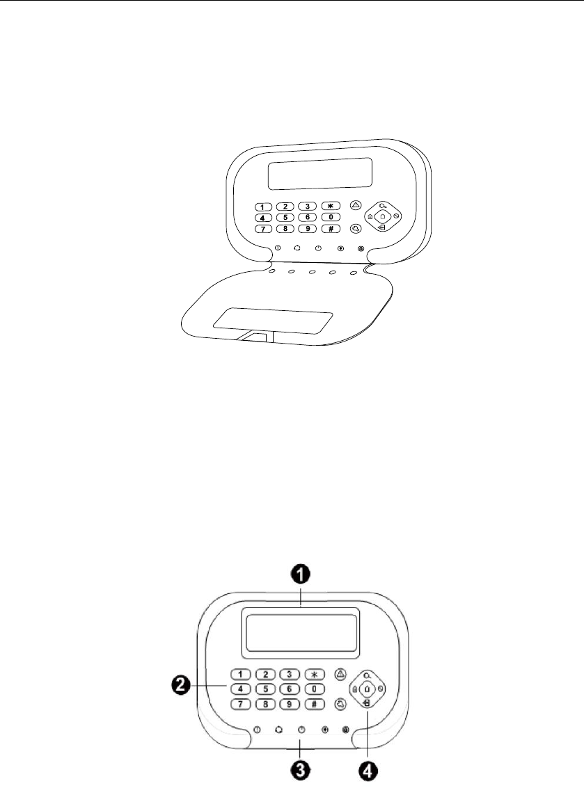
1.2 Appearance Description
Keypad User Manual
9
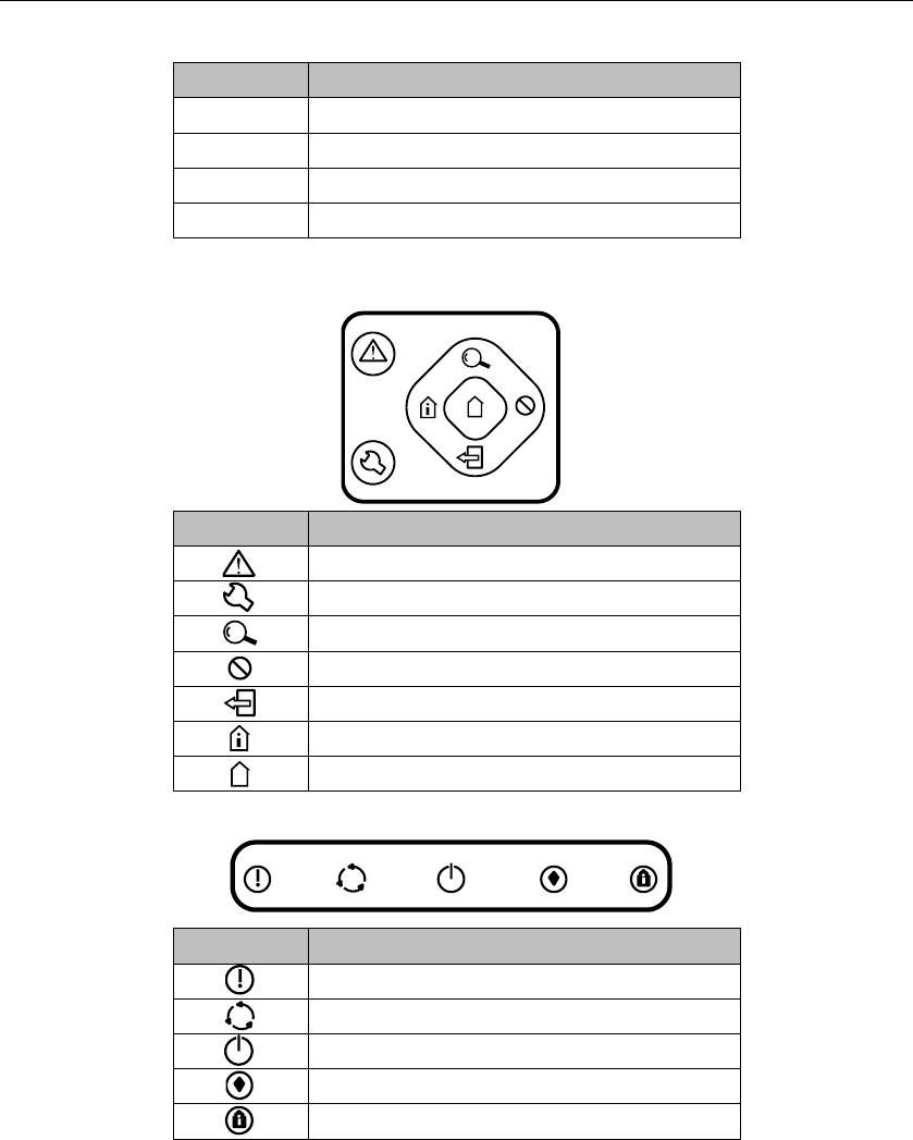
No.
Description
1
LCD Screen
2
Keypad
3
Control Panel
4
Indicator Bar
Control Panel
Button
Description
Panic Button
Programming Button
Search Button
Bypass Button
Exit Button
Stay Arming Button
Away Arming Button
Indicator Bar
Button
Description
Status Indicator
Operating Indicator
Power Indicator
Arming Indicator
Stay Arming Indicator

Keypad User Manual
10
1.3 Keypad Beeper and Indicator
Beeper Description
No.
Sound Prompt
Description
1
One Beep
Pressing keys prompt; The command is timed
out or the command is too long.
2
Two Beeps
Valid command. Uploading the report
completed.
3
Five Beeps
Invalid command. Failed to upload the report
in 60s.
4
Continuous Beeping
For Two Seconds
Fault Prompt
5
Slowly Continuous
Beeps
Entry/Exit Delay
6
Rapidly Continuous
Beeps
Entry/Exit Delay, less than 10s.
7
Rapid Beeps
Zone Alarm; The keyboard is not registered.
8
Three Long Beeps
and Two Short Beeps
The tampering prevention of the keyboard is
turned on.
9
Three Beeps
Registering the keyboard completed.
10
One Beep In Two
Seconds
Two minutes before auto arming/disarming;
One minute before arming for temporary
password.
11
Three Beeps In One
Second
One minute before auto arming/disarming; 15s
before arming for temporary password.

Keypad User Manual
11
Indicator Description
Status
Working Status
Indicator
Working Status
Indicator
Normal
Solid Green
System Fault
Solid Red
Power
Working Status
Indicator
Power On
Solid Green
Stay
Working Status
Indicator
Working Status
Indicator
Partition Perimeter
Disarmed
OFF
Partition System
Perimeter Armed
Orange
Arm
Working Status
Indicator
Working Status
Indicator
Partition Armed
Solid Red
Partition System
Disarmed
Solid Green
Password Modifying
Flicking Green
Fob Code Matching
Flicking Green
Testing Mode
Solid Red
Programming
Flicking Green
OPERATING
Working Status
Indicator
Working Status
Indicator
Normal
Solid Green
Programming
Flicking Green
Password Modifying
Flicking Green
Fob Code Matching
Flicking Green
Engineering Mode
Solid Red
System Fault
Flicking Orange

Keypad User Manual
12
LED Zone Indicator
Zone
Working Status
Indicator
Working Status
Indicator
Normal
OFF
Fault
Solid Red
Alarm
Flicking Red
Bypass
Solid Green
Zone Indicator under Engineering Mode (The corresponding zone indicator light
will turn orange when operating):
No.
Description
No.
Description
1
Off Hook
5
Sending CID Report
2
Dialing
6
Receiving Confirmation
3
Alarm Receiver Off
Hook
7
Control Panel On Hook
4
Receiving Handshake
8
Alarm Receiver On Hook
Zone Indicator under Status Mode (The corresponding indicator light will be solid
red if there is any fault):
No.
Description
No.
Description
1
AC Current Interrupted
5
RS-485 Device
Disconnected
2
Low Voltage of Storage
Battery
6
Wired Network Exception
3
Movement Prevention of
Control Panel Turning On
7
Wireless Network
Exception
4
Telephone Line
Disconnected
8
Reserved
Keypad User Manual
13
Chapter 2 Installation and Wiring
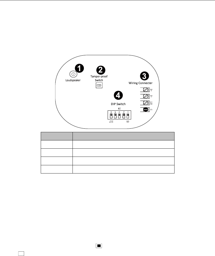
2.1 Wiring Connector Description
No.
Description
1
Loud Speaker
2
Tamper-Proof Switch
3
Wiring Connector
4
DlP Switch
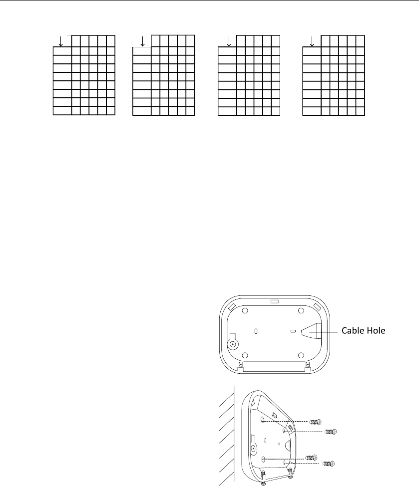
2.2 Keypad Address Settings
An address is required for each alarm keypad in the system. These addresses
cannot be repeated. Once exchanging the alarm keypad, the address of the new
keypad must be the same as the replaced one. You should configure the address
via DIP switch of the keypad before powering on the system. The address should
be in the range of 1~31.
When it is black on the end of ON as , indicated 1; when it is black on the other
end as , indicated 0.
Keypad User Manual
14
1 2 3 4 5
00
01 ■
02 ■
03 ■ ■
04 ■
05 ■ ■
06 ■ ■
07 ■ ■ ■
1 2 3 4 5
08 ■
09 ■ ■
10 ■ ■
11 ■ ■ ■
12 ■ ■
13 ■ ■ ■
14 ■ ■ ■
15 ■ ■ ■ ■
12345
16 ■
17 ■ ■
18 ■ ■
19 ■ ■ ■
20 ■ ■
21 ■ ■ ■
22 ■ ■ ■
23 ■ ■ ■ ■
12345
24 ■ ■
25 ■ ■ ■
26 ■ ■ ■
27 ■ ■ ■ ■
28 ■ ■ ■
29 ■ ■ ■ ■
30 ■ ■ ■ ■
31 ■ ■ ■ ■ ■
Keyboard
Address ON DIP
Keyboard
Address
Keyboard
Address
Keyboard
Address
ON DIPON DIPON DIP
2.3 Keypad Installation
Before You Start:
Make sure that the device in the package is in good condition and all the
assembly parts are included.
Make sure that the wall is strong enough to withstand three times the weight
of the keypad.
Set the keypad address before installation.
Steps:
1. Route the cables through the cable
hole of the mounting plate.
2. Secure the mounting plate on the
wall with 4 supplied screws.
Keypad User Manual
15
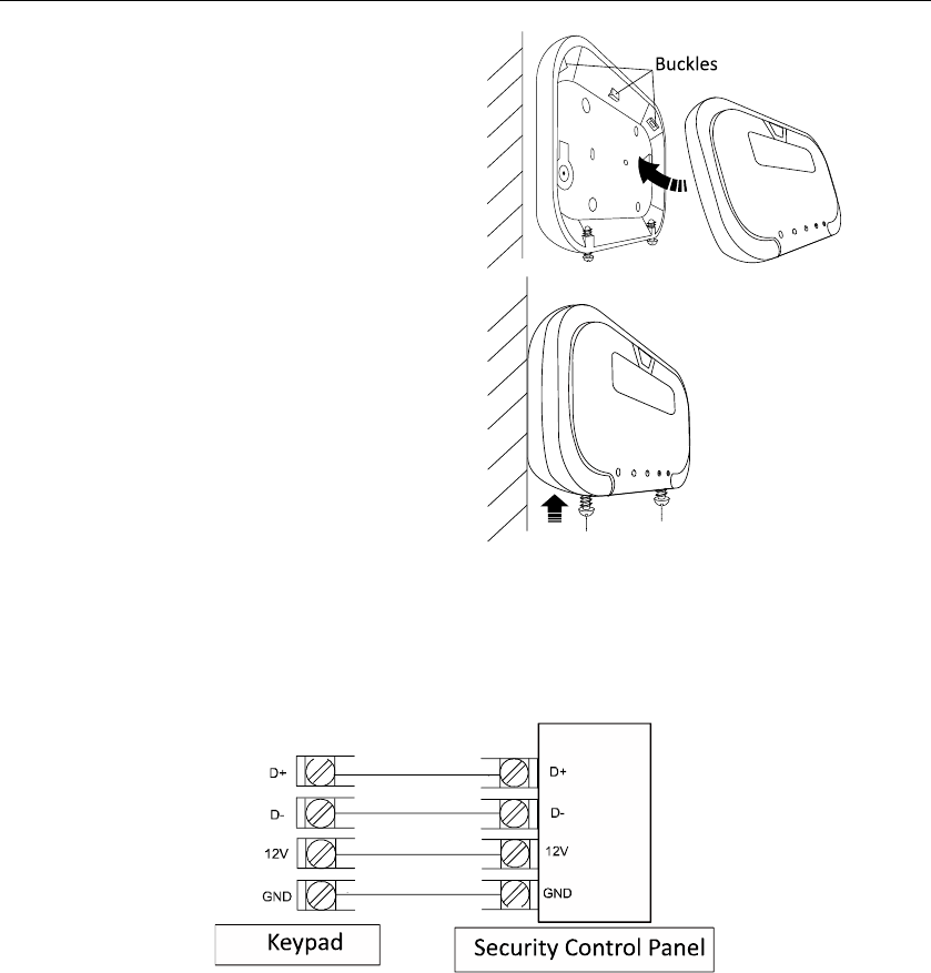
3. Connect the corresponding cables.
4. Push the keypad body in the
mounting plate from bottom up.
5. Fasten the keypad body with the
three buckles on the plate.
6. Align the screw holes with the
screws on the bottom of both
keypad and mounting plate.
7. Tighten the screws to fix the keypad
on the mounting plate and complete
the installation.
2.4 Keypad Wiring
The keypad wiring is shown as follows.
Chapter 3 Keypad Operation (Local
Operation)
3.1 Keypad Alarm Operation Code

Keypad User Manual
16
Function
Description
Command
Arming/Disarming
Normal(Away)Arming/Disarming
【Password】【 #】
Instant Arming
【Password】【 *】【 7】【 #】
Stay Arming
【Password】【 *】【 4】【 #】
Normal (Away)Arming/Disarming
【Password】【 Bypass】【 #】
Mandatory
【Password】【 *】【 7】【 Bypass】【 #】
Mandatory Instant Arming
【Password】【 *】【 4】【 Bypass】【 #】
Bypass
Bypass Zone(n)
【Password】【 Bypass】【 n】【 n】【 n】【 #】
【Bypass】【 n】【 n】【 n】【 #】
nnn is the zone No.
Group Bypass
【Password】【 *】【 4】【 1】【 #】
Group Bypass
【Password】【 *】【 4】【 2】【 #】
Programming/
Editing Password
Control Panel Programming
【Installer Password】【 *】【 0】【 #】
Exit Operation
【*】【 #】
Operator Password
【Operator Password】【 *】【 0】【 #】
【User No. (3digits)】【 #】
【New Password】【 #】
【New Password】【 #】
Clearing Alarm
Clearing Under arming status
Clearing under disarming status
【*】【 1】【 #】
【Password】 【*】【 1】【 #】
Keypad Settings
Enabling/Disabling Keypad Tone
【*】【 5】【 1】【 #】
Enabling/Disabling Fault Prompt
【*】【 5】【 6】【 #】
LCD Backlight Control
【*】【 5】【 2】【 n】【 n】【 n】【 #】
LCD Backlight Disabling
【*】【 8】【 #】
Testing
Testing
【Password】【 *】【 6】【 0】【 #】
Alarm Center Testing
【Password】【 *】【 6】【 1】【 #】
Project Mode
【Password】【 Project】【 9】【 0】【 n】【 #】
Exiting Project Mode
【Project】 or 【*】【 #】
Display/Output
Enabling Alarm Output
【Password】【 *】【 8】【 5】【 n】【 n】【 #】
Disabling Alarm Output
【Password】【 *】【 8】【 6】【 n】【 n】【 #】
System Settings
Control Panel Soft Resetting
【Operator Password】【 *】【 6】【 8】【 #】
Initialization
【Installer Password】【 *】【 8】【 9】【 #】
Panic Alarm
Panic Alarm
【Panic】

Keypad User Manual
17
Device Status Query
System Fault Status
【Status】
Wireless User
Settings
Pairing Wireless Device and
Control Panel
【Password】【 *】【 91】【 No.】【 #】
Deleting the Specified Connected
Wireless Device
【Password】【 *】【 90】【 No.】【 #】
Deleting all the Connected
Wireless Device
【Password】【 *】【 92】【 #】
Card User Settings
Pairing Card No. and Control
Panel
【Operator】 【Project】【 10】【User No.】 【#】
Deleting the Specified Card
【Operator】【 Project】【 11】【 Card No.】【 #】
【Operator】【 Project】【 12】【 #】
Deleting All Card Of a Specified
User
【Operator】【 Project】【 15】【 #】
Exiting Card Pairing Mode
【*】【 #】
Schedule
Resetting Current Schedule
【Installer Password】【 *】【 8】【 1】【 #】
Clearing Weekly Schedule
【Installer Password】【 *】【 8】【 2】【 #】
Clearing Prioritized Schedule
【Installer Password】【 *】【 8】【 3】【 #】
Single Zone
Operation
Arming/Disarming
【Password】【 Project】【 n】【 n】【 n】【 #】
Clearing Alarm
【Password】【 Project】【 n】【 n】【 n】【 #】
Language Settings
Displaying English
【*】【 9】【1】【 1】【 #】
Displaying Chinese
【*】【 9】【 1】【 0】【 #】