Hangzhou Hikvision Digital Technology 19ABNG Network Security Control Panel User Manual
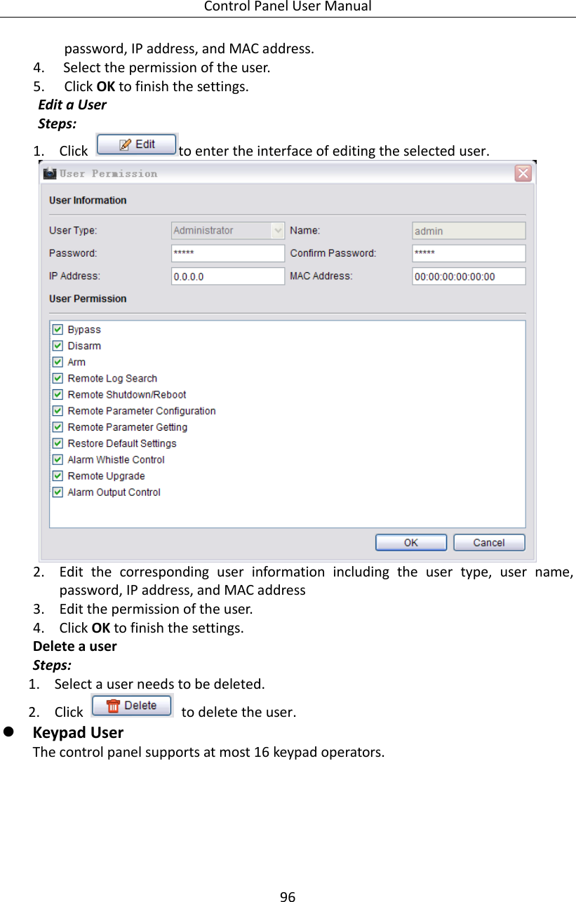
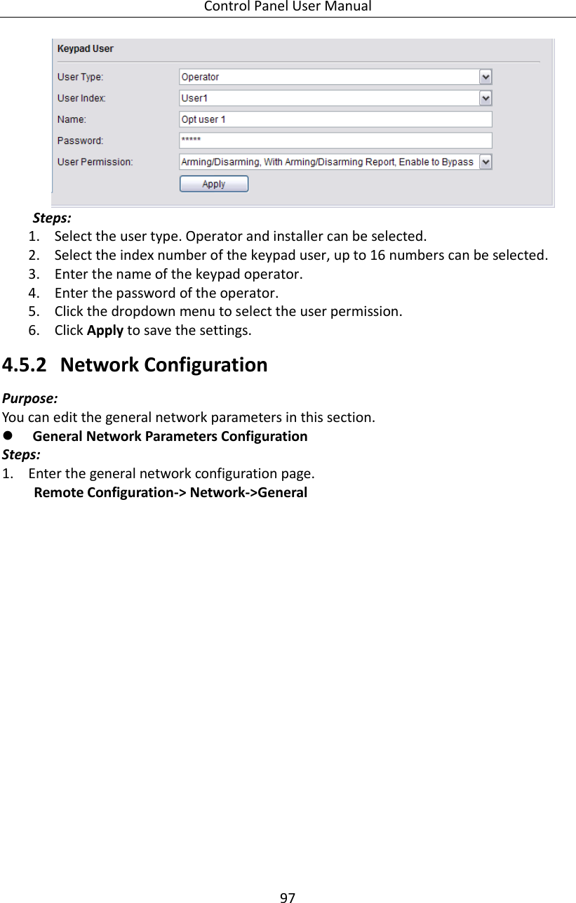
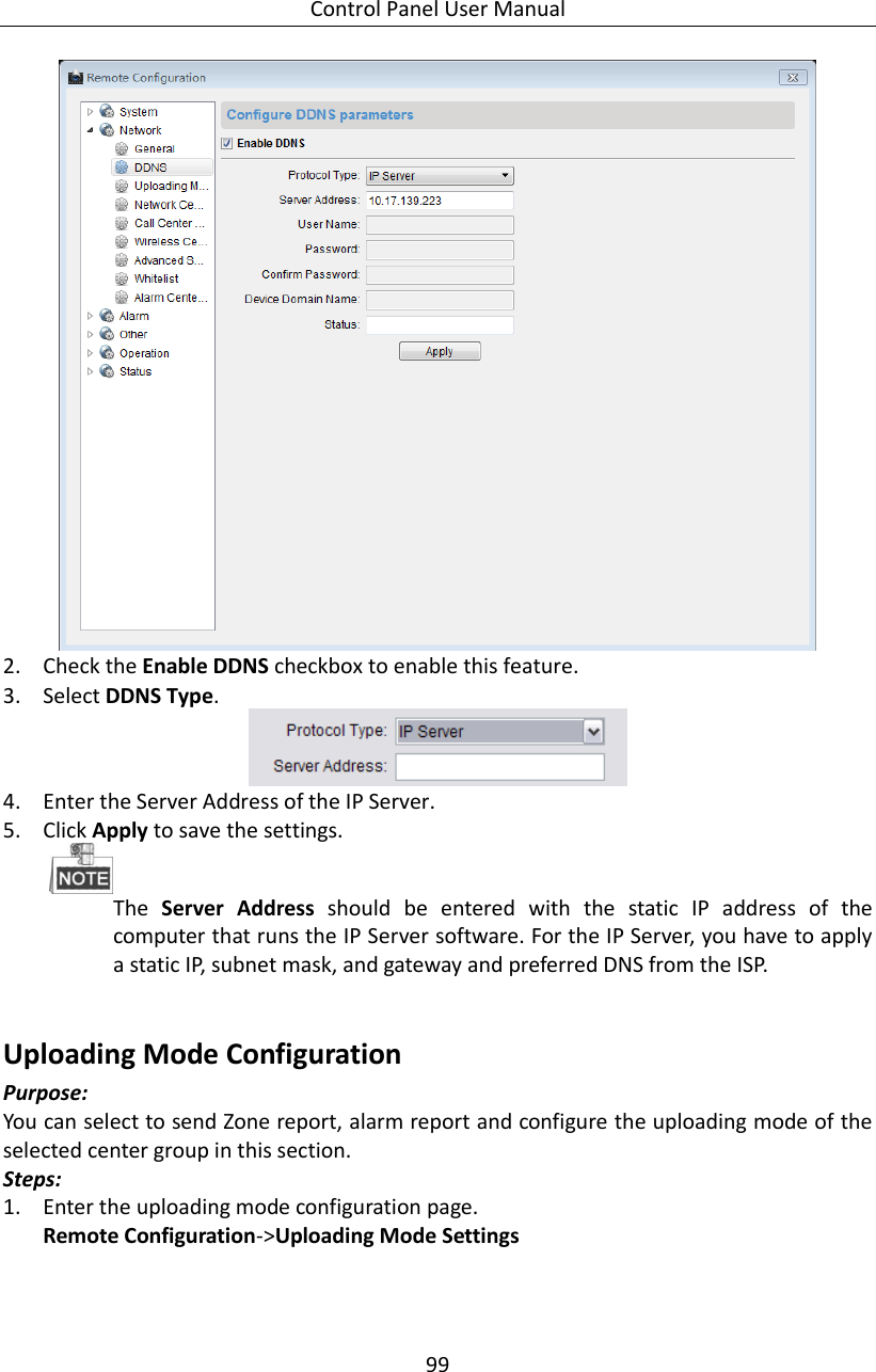
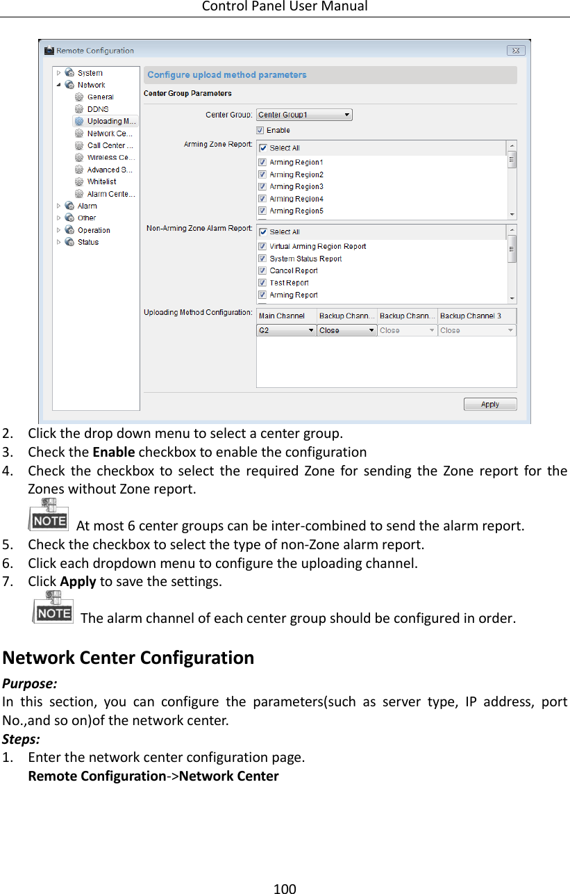
Hangzhou Hikvision Digital Technology Co., Ltd. Network Security Control Panel Users Manual
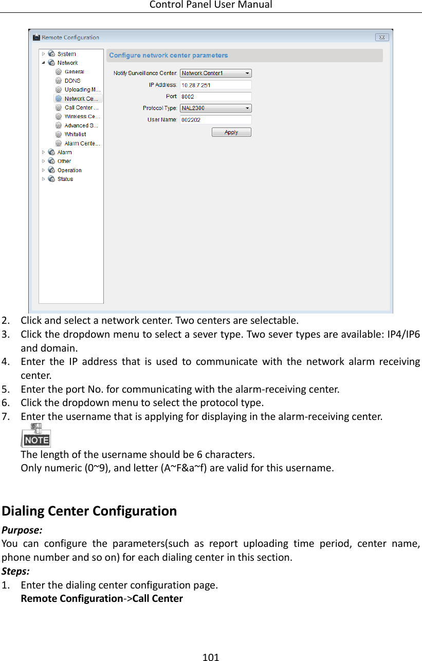
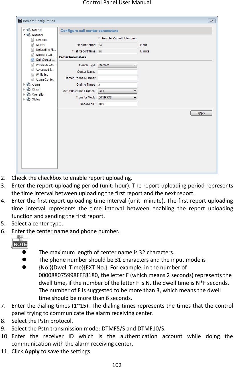
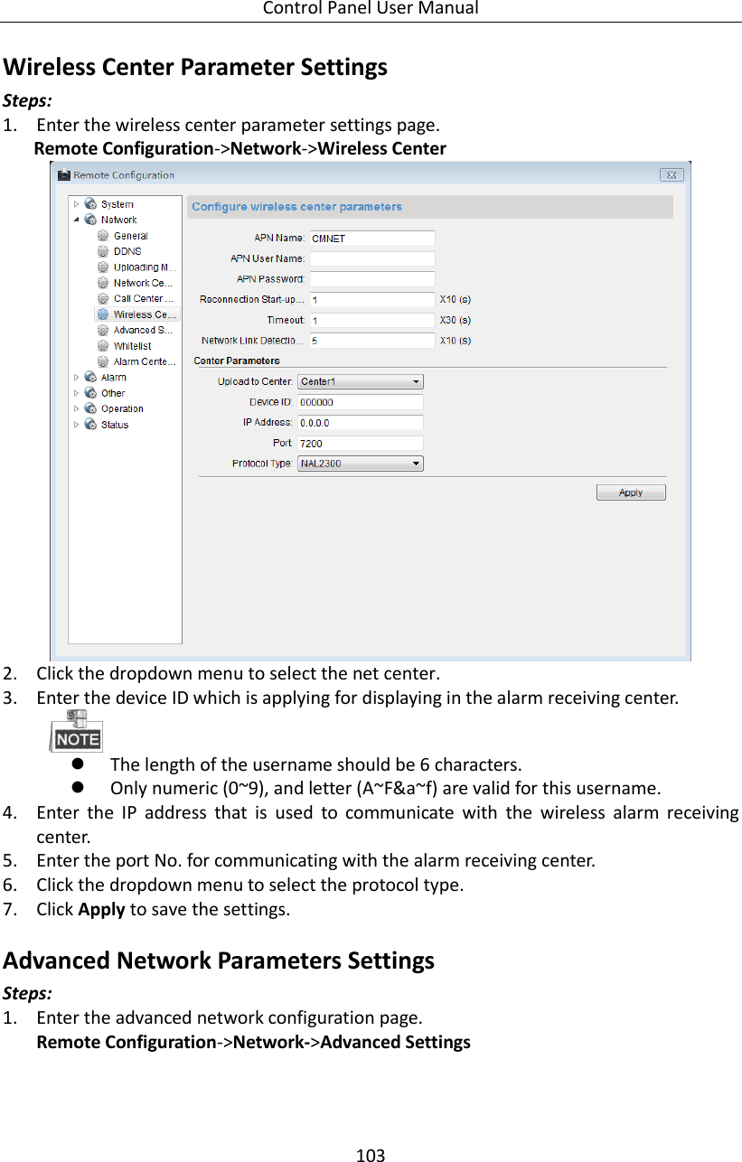
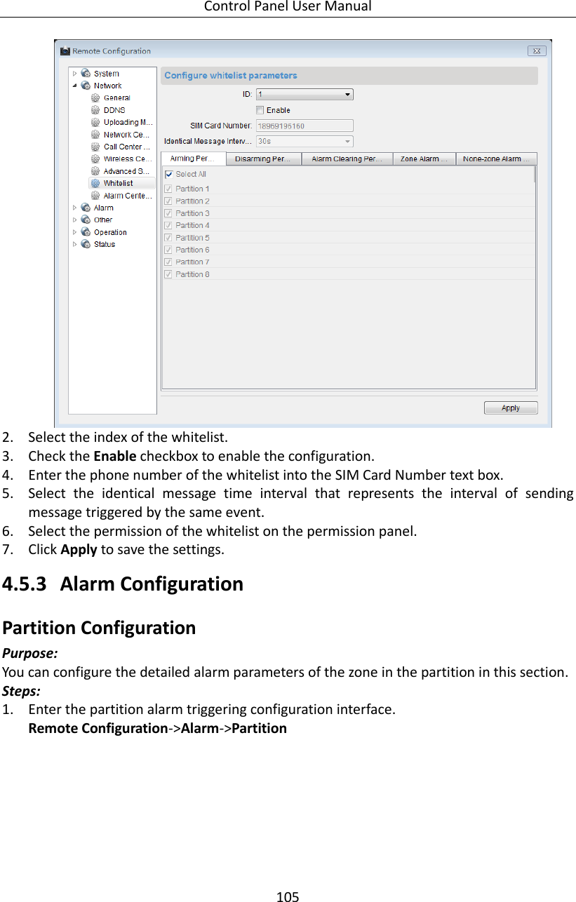
UserManual.wiki
>
Hangzhou Hikvision Digital Technology
>
19ABNG User Manual
Users Manual
Navigation menu
Upload a User Manual
Namespaces
Wiki Guide
HTML
PDF
Info
Views
User Manual
Discussion / Help
Navigation


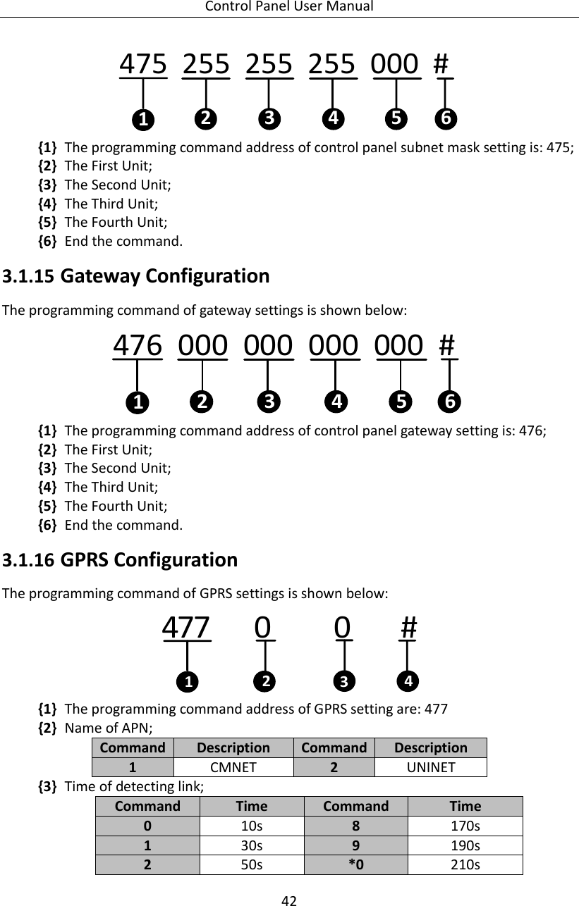

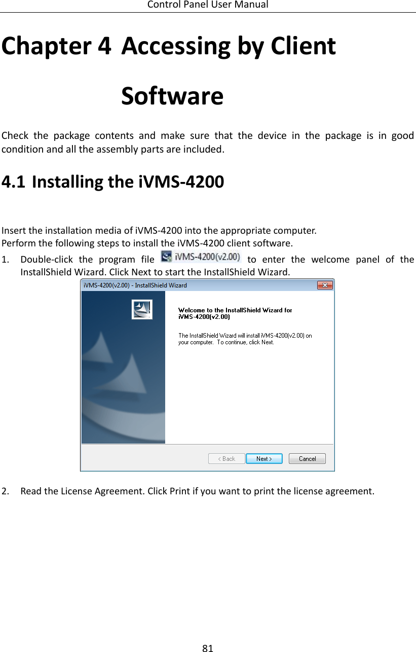
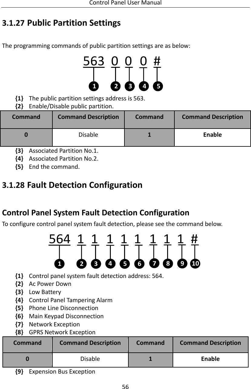
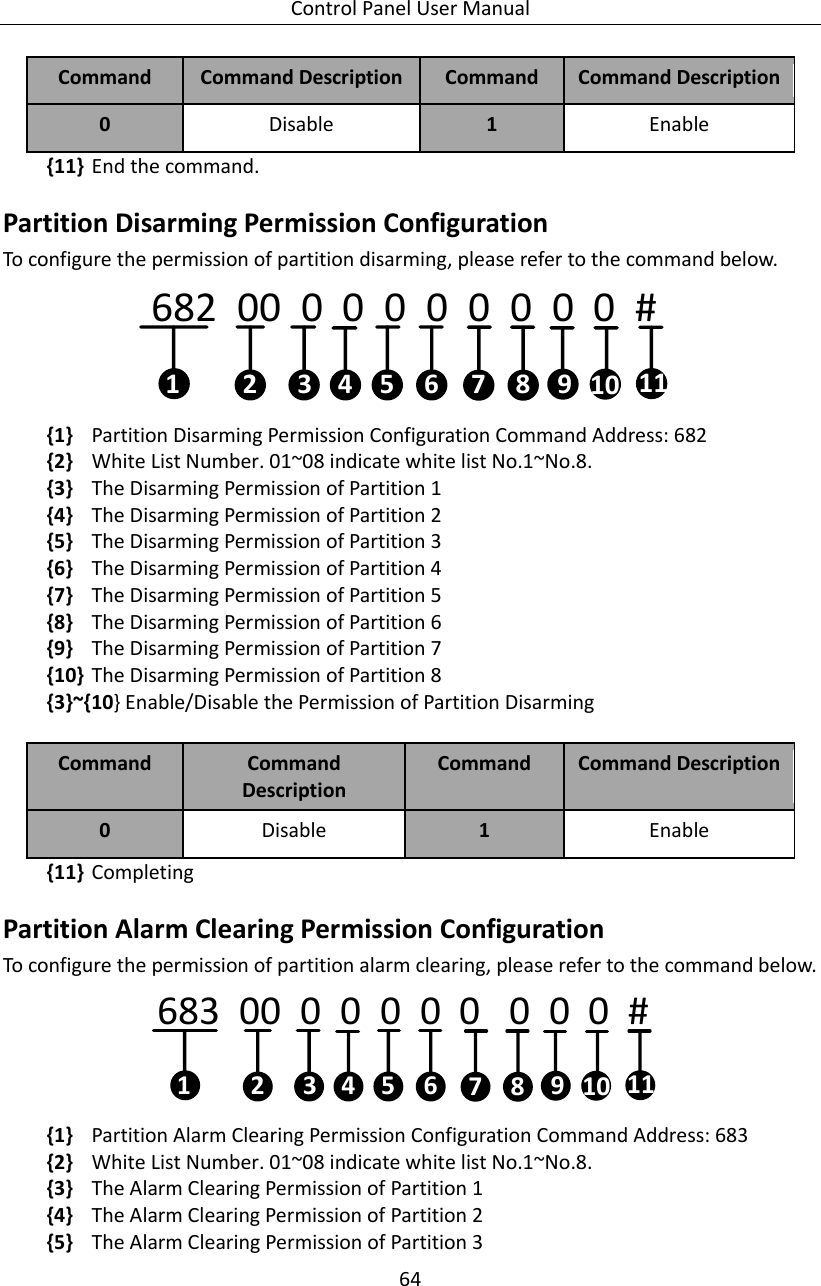
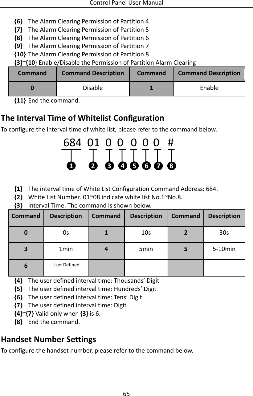
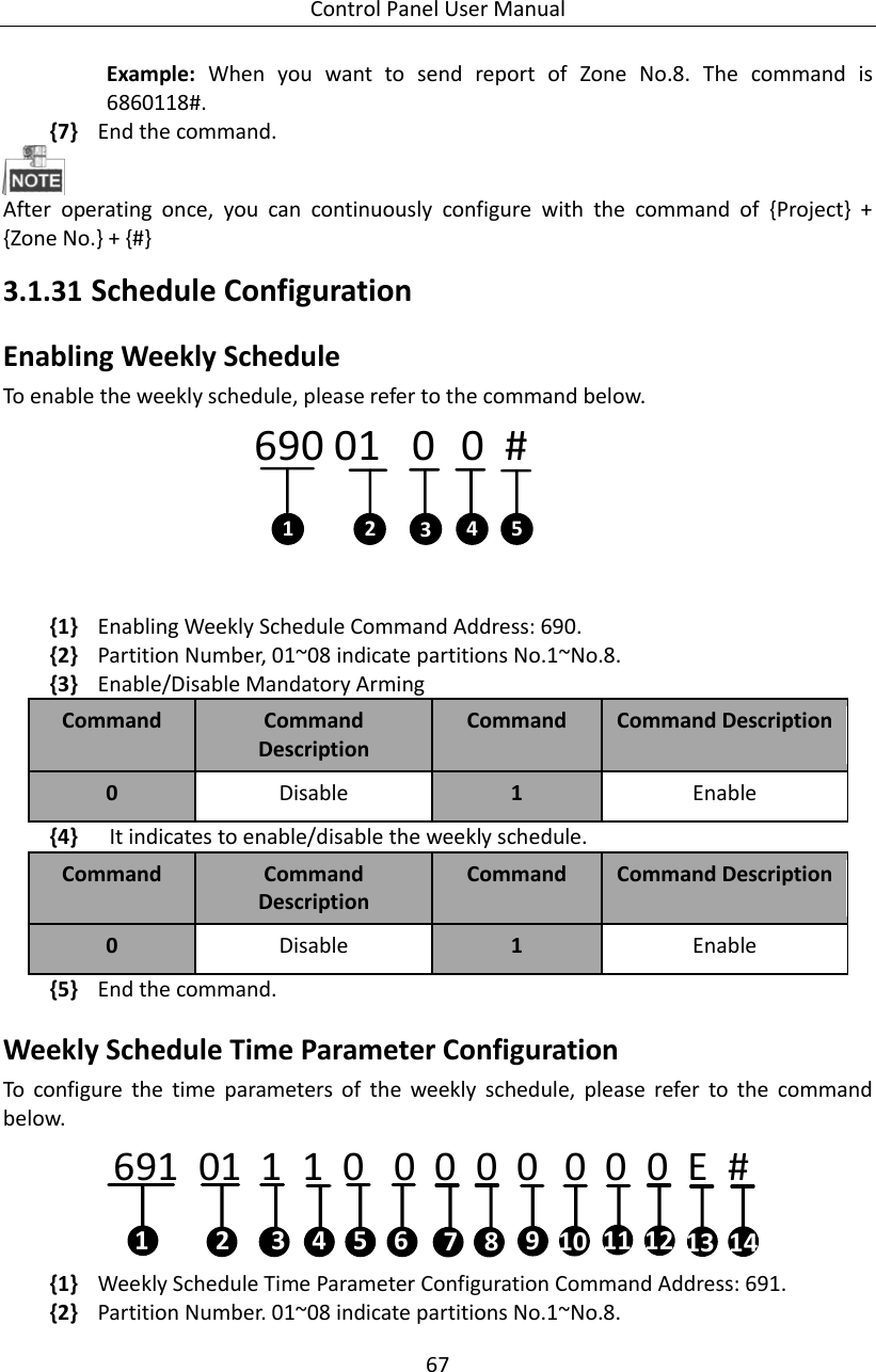
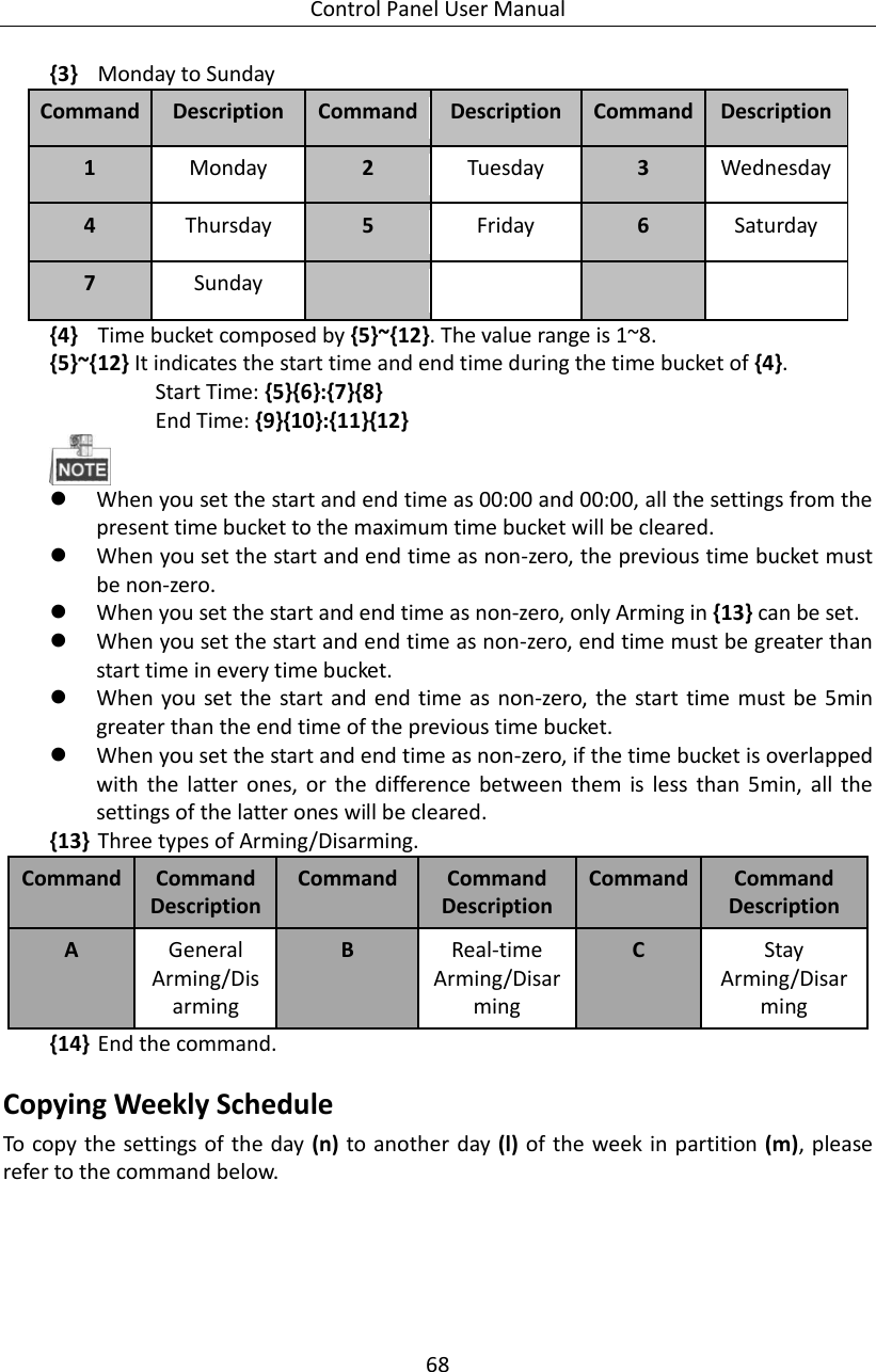
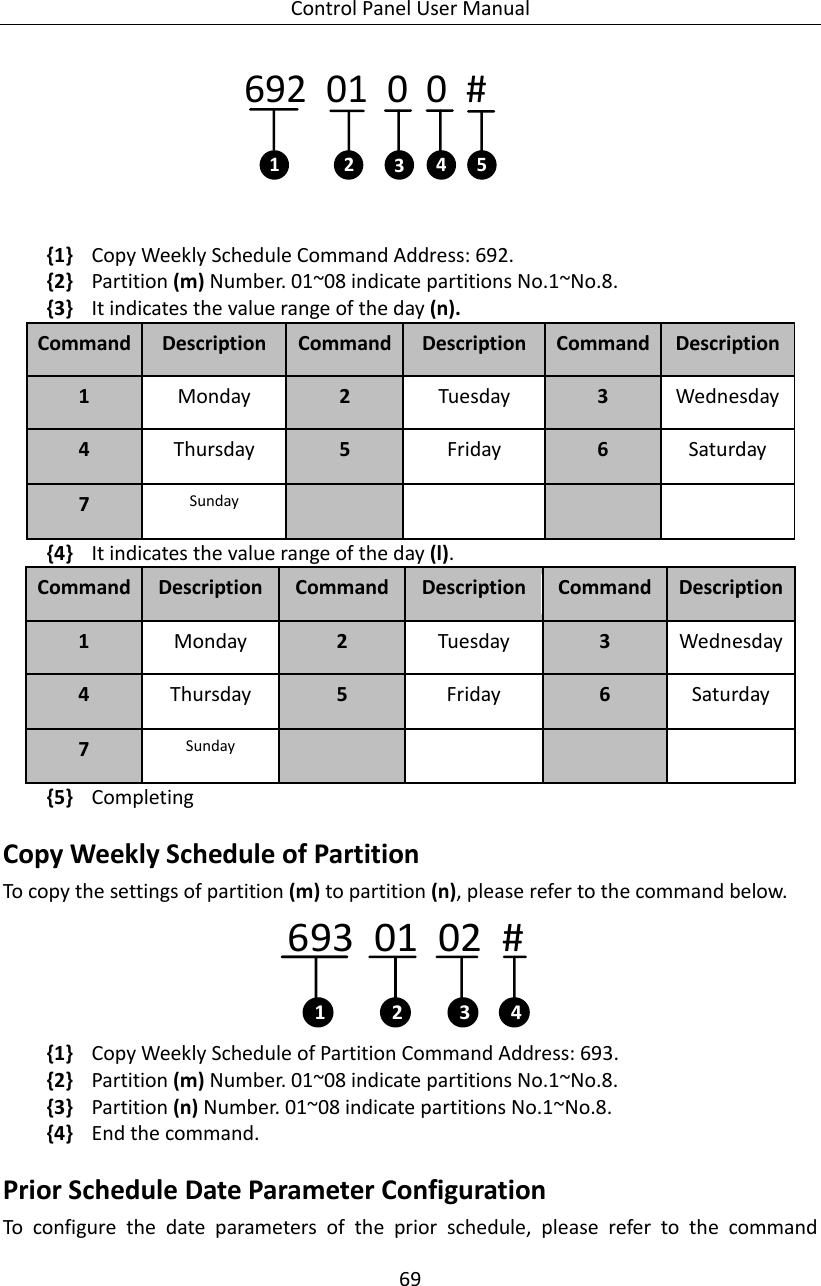
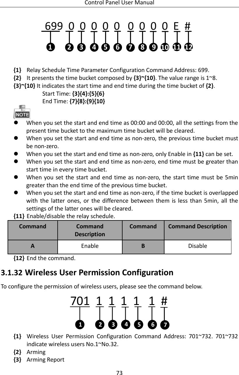
![Control Panel User Manual 52 {4} End the command. Only the No.1 partition is enabled as the default settings. Partition Keypad User Configuration The programming command of keypad user configuration of the partition is shown as follows. 531 2 0 000 #14235 {1} The programming command address of keypad user configuration is 531~538. {2} The configuration item of 2 indicates the keypad user configuration. {3} Add/Delete the user. Command Command Description Command Command Description 0 Delete 1 Add {4} The user No. {5} End the command Added Separately: for instance, to add an user with the No. of 160 to the No.8 partition, the command should be 538 2 1 160 # Added/Deleted Continually: only continuous adding or deleting operation is supported. After adding/deleting a user separately, enter the command [Project]+[User No.]+[#] to continually add/delete users. For instance, to add users with the No. of 2,3,and 5, the command should be 538 2 1 002 # Project # 003 # Project # 005 #. Added/Delete in Batch: the formate is 531 2 x xxx xxx #. Added with user No. interval: for instance, to add users with the No. between 100~149 to the No.3 partition, the command should be 533.2.1.100.149 #. Partition Zone Configuration The programming command of zone configuration of the partition is shown below.](https://usermanual.wiki/Hangzhou-Hikvision-Digital-Technology/19ABNG/User-Guide-2997027-Page-53.png)
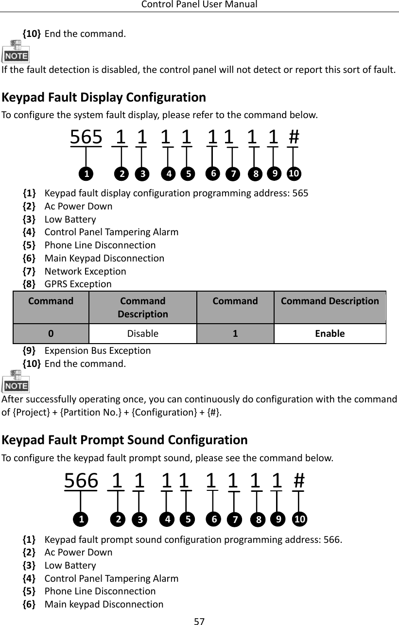

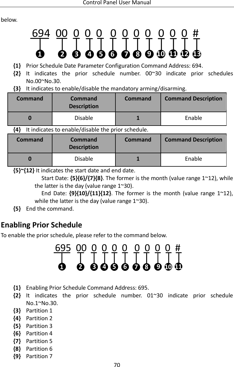
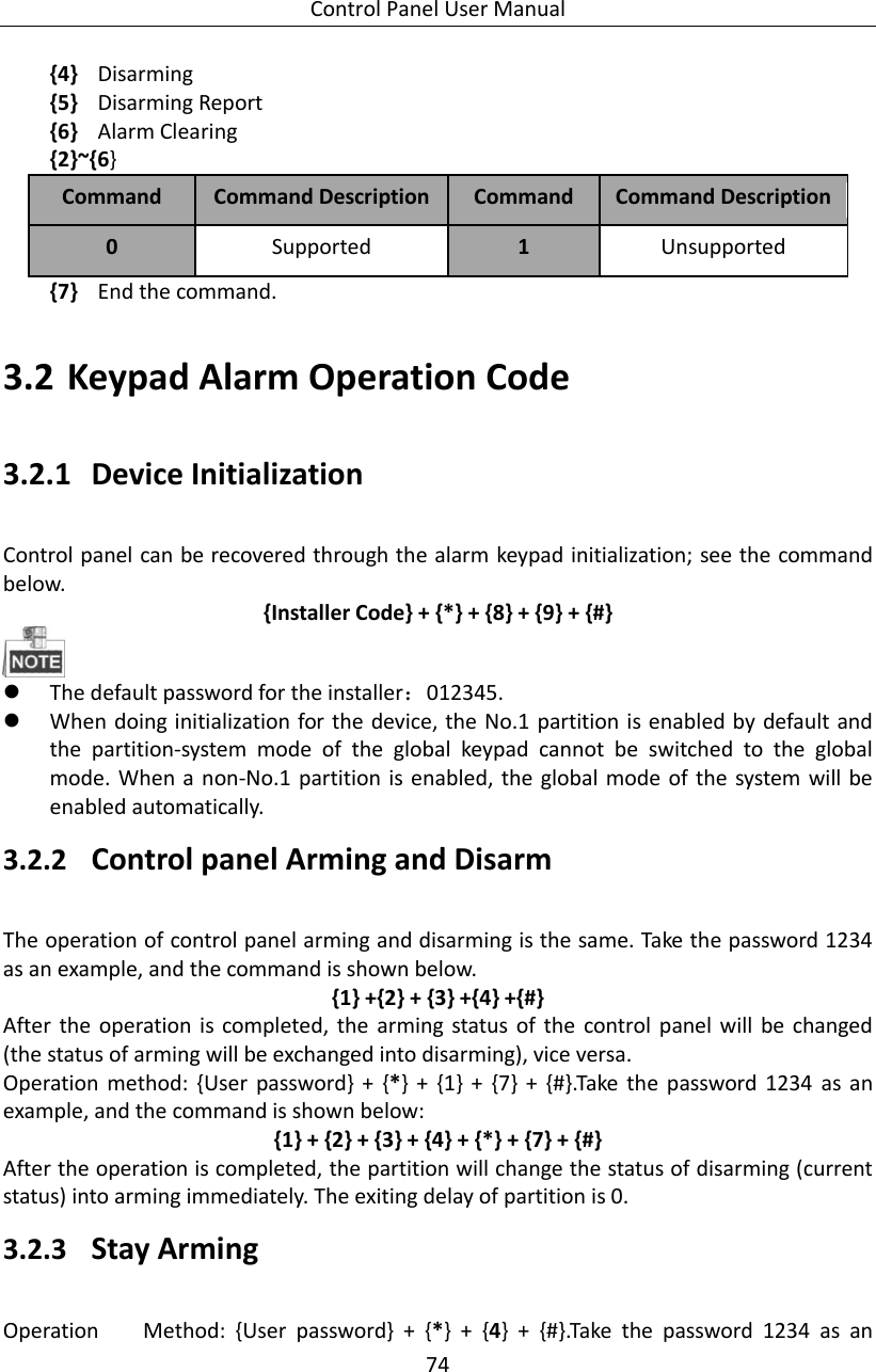
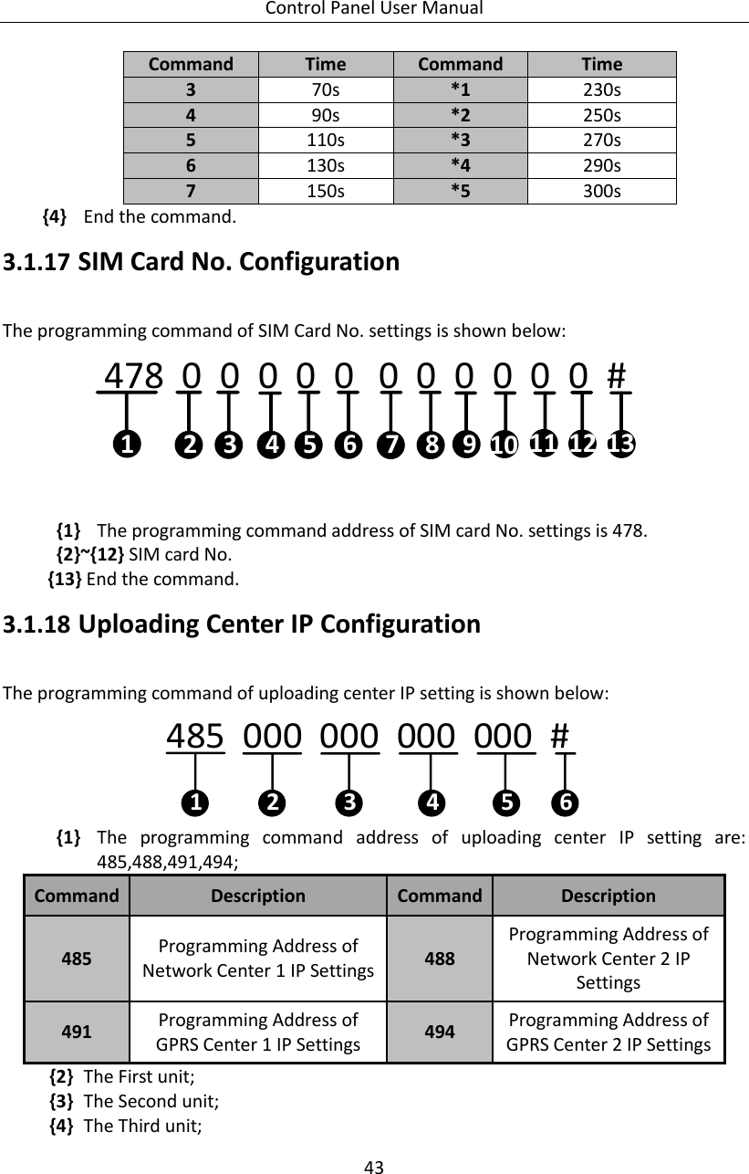
![Control Panel User Manual 75 example, and the operation is shown as follows: {1} + {2} + {3} + {4} + {*} + {4} + {#} After the operation is completed, the partition will change the status of disarming (current status) into arming immediately. The bypass-supported zone of the partition will do auto-bypass simultaneously. 3.2.4 Zone Bypass/Recovery After bypassing a zone, all the alarm devices in this zone will be blocked. ; see the command below {User password} + {bypass} + {Zone Number} + {#} For continuous bypass/ recovery; see the command below: [1234] [1][Bypass][#]+++[2][Bypass] [#]++ [Bypass][ # ]++[ 8]……15 Seconds Continuous operation of multi-zone bypass/ recovery should be completed within 15 seconds 3.2.5 Group Bypass After a partition is conducted with group bypass, all the alarm devices in group-bypass supported zone of the partition will be blocked. See the command below. {User Password} + {*} + {4} + {1} + {#} 3.2.6 Group Bypass Recovery After recovering the group bypass of a partition, all the alarm devices in group-bypass supported zone of the partition will be revalidated. See the command below. {User Password} + {*} + {4} + {2} + {#} 3.2.7 Canceling Keypad Alarm When the alarm is trigged, it can be canceled by keypad. The alarm can be canceled both under the arming and the disarming status. Alarm Clearing under the Arming Status Operation Method: {User Password} + {*} + {1} + {#} Alarm clearing under the disarming Status](https://usermanual.wiki/Hangzhou-Hikvision-Digital-Technology/19ABNG/User-Guide-2997027-Page-76.png)